JP6079662B2 - Lower body structure - Google Patents
Lower body structure Download PDFInfo
- Publication number
- JP6079662B2 JP6079662B2 JP2014026744A JP2014026744A JP6079662B2 JP 6079662 B2 JP6079662 B2 JP 6079662B2 JP 2014026744 A JP2014026744 A JP 2014026744A JP 2014026744 A JP2014026744 A JP 2014026744A JP 6079662 B2 JP6079662 B2 JP 6079662B2
- Authority
- JP
- Japan
- Prior art keywords
- vehicle body
- width direction
- underfloor
- cross member
- floor
- Prior art date
- Legal status (The legal status is an assumption and is not a legal conclusion. Google has not performed a legal analysis and makes no representation as to the accuracy of the status listed.)
- Expired - Fee Related
Links
Images


Classifications
-
- B—PERFORMING OPERATIONS; TRANSPORTING
- B62—LAND VEHICLES FOR TRAVELLING OTHERWISE THAN ON RAILS
- B62D—MOTOR VEHICLES; TRAILERS
- B62D25/00—Superstructure or monocoque structure sub-units; Parts or details thereof not otherwise provided for
- B62D25/20—Floors or bottom sub-units
- B62D25/2009—Floors or bottom sub-units in connection with other superstructure subunits
- B62D25/2045—Floors or bottom sub-units in connection with other superstructure subunits the subunits being fire walls
-
- B—PERFORMING OPERATIONS; TRANSPORTING
- B62—LAND VEHICLES FOR TRAVELLING OTHERWISE THAN ON RAILS
- B62D—MOTOR VEHICLES; TRAILERS
- B62D25/00—Superstructure or monocoque structure sub-units; Parts or details thereof not otherwise provided for
- B62D25/20—Floors or bottom sub-units
Landscapes
- Engineering & Computer Science (AREA)
- Chemical & Material Sciences (AREA)
- Combustion & Propulsion (AREA)
- Transportation (AREA)
- Mechanical Engineering (AREA)
- Body Structure For Vehicles (AREA)
Description
本発明は、車体下部構造に関する。 The present invention relates to a vehicle body lower structure.
衝突時における車体下部の変形を抑えるための構造が従来から提案されている(例えば、特許文献1〜特許文献3参照)。例えば、ダッシュクロスメンバの一端部がトンネルメンバを介してトンネルの側面に接合されると共に、ダッシュクロスメンバの他端部がAピラーに接合され、さらに前記トンネルメンバがトンネルの上面を跨いでトンネルに接合された構造がある(例えば、特許文献1参照)。このような構造では、トンネルメンバによってトンネルの剛性が高められており、ダッシュクロスメンバに車体幅方向内側への荷重が入力された場合、当該荷重をトンネル部側に伝達させる。 Conventionally, a structure for suppressing deformation of the lower part of the vehicle body at the time of a collision has been proposed (see, for example, Patent Documents 1 to 3). For example, one end of the dash cross member is joined to the side surface of the tunnel through the tunnel member, the other end of the dash cross member is joined to the A pillar, and the tunnel member is further connected to the tunnel across the upper surface of the tunnel. There is a bonded structure (see, for example, Patent Document 1). In such a structure, the tunnel member enhances the rigidity of the tunnel, and when a load inward in the vehicle body width direction is input to the dash cross member, the load is transmitted to the tunnel portion side.
しかしながら、上記構造では、車室空間が狭められてしまうため、この点において改善の余地がある。 However, in the above structure, the passenger compartment space is narrowed, so there is room for improvement in this respect.
本発明は、上記事実を考慮して、車室空間が狭まるのを抑えながらダッシュクロスメンバへの荷重入力時にトンネルの変形を抑えて効率良く荷重を伝達させることができる車体下部構造を得ることが目的である。 In view of the above facts, the present invention can provide a vehicle body lower structure that can efficiently transmit a load by suppressing deformation of the tunnel when a load is input to the dash cross member while suppressing a narrowing of a passenger compartment space. Is the purpose.
請求項1に記載する本発明の車体下部構造は、車体前部と車室とを隔成するダッシュパネルの下部側に連接して車体後方側に延びる車体フロアと、前記ダッシュパネルの下部後面側から前記車体フロアにかけての車体幅方向中央部に設けられ、車体前後方向に延在するトンネルと、車体側部において車体前後方向に延在して前記車体フロアの車体幅方向外側に設けられたロッカと、前記ダッシュパネルの下部後面に接合され、前記トンネルの側壁部の前端部の下側部分と、前記ロッカの前端部と、を車体幅方向に架け渡すダッシュクロスメンバと、前記トンネルの前端部に対して車室側とは反対側に設けられて車体幅方向に延在すると共に、車体幅方向の両端部が前記トンネルの前端部よりも車体幅方向外側に設定されかつ前記ダッシュパネルに直接又は他部材を介して固定され、前記ダッシュパネルを挟んで前記ダッシュクロスメンバの車体幅方向内側の端部の対向位置に、車体幅方向の端部が設定された床下ブレースと、を有し、前記ダッシュクロスメンバは、車体幅方向に沿う第一稜線を備え、前記床下ブレースは、車体幅方向に沿う第二稜線を備え、前記第二稜線の車体幅方向の端部は、前記床下ブレースの車体幅方向の端部が前記ダッシュパネルを挟んで前記ダッシュクロスメンバの車体幅方向内側の端部に対向する方向に見て前記第一稜線と重なる位置に設定されている。 The vehicle body lower part structure of the present invention described in claim 1 includes a vehicle body floor that is connected to a lower side of a dash panel that separates a front part of the vehicle body and a passenger compartment and extends toward the rear side of the vehicle body, and a lower rear surface side of the dash panel. A tunnel extending in the vehicle body width direction from the vehicle body floor to the vehicle body floor and extending in the vehicle body front-rear direction, and a rocker extending in the vehicle body front-rear direction at the vehicle body side and provided outside the vehicle body width direction of the vehicle body floor A dash cross member that is joined to the lower rear surface of the dash panel and bridges the lower part of the front end of the side wall of the tunnel and the front end of the rocker in the vehicle body width direction, and the front end of the tunnel The both ends of the vehicle body width direction are set on the outer side in the vehicle body width direction with respect to the front end portion of the tunnel and the dash panel is provided. Yes fixed directly or via another member, a position facing the vehicle width direction inner ends of the dash cross member across the dash panel, a floor brace end portion of the vehicle body width direction is set, to The dash cross member includes a first ridge line along the vehicle body width direction, the underfloor brace includes a second ridge line along the vehicle body width direction, and an end portion of the second ridge line in the vehicle body width direction includes the under floor The end of the brace in the vehicle width direction is set at a position overlapping the first ridge line when viewed in a direction facing the inner end of the dash cross member in the vehicle width direction across the dash panel .
上記構成によれば、ダッシュパネルの下部後面には、ダッシュクロスメンバが接合されており、ダッシュクロスメンバは、トンネルの側壁部の前端部の下側部分と、ロッカの前端部と、を車体幅方向に架け渡している。そして、トンネルの前端部に対して車室側とは反対側には、車体幅方向に延在する床下ブレースが設けられている。床下ブレースの車体幅方向の両端部は、トンネルの前端部よりも車体幅方向外側に設定されかつダッシュパネルに直接又は他部材を介して固定されており、ダッシュパネルを挟んでダッシュクロスメンバの車体幅方向内側の端部の対向位置に、床下ブレースの車体幅方向の端部が設定されている。このため、例えば、ダッシュクロスメンバの左右両端部が車体側部の骨格部材に接合されると共にダッシュクロスメンバの車体幅方向中央部がトンネルの上部を跨ぐ対比構造に比べて、車室空間を大きく設定することができる。また、衝突時にダッシュクロスメンバに対して車体幅方向内側へ向けた荷重が入力された場合には、床下ブレースが突っ張り支持してトンネルの変形を抑える。 According to the above configuration, the dash cross member is joined to the lower rear surface of the dash panel, and the dash cross member connects the lower portion of the front end portion of the side wall portion of the tunnel and the front end portion of the rocker to the vehicle body width. It spans the direction. An underfloor brace extending in the vehicle body width direction is provided on the side opposite to the passenger compartment side with respect to the front end portion of the tunnel. Both ends of the underfloor brace in the vehicle body width direction are set to the vehicle body width direction outside of the front end of the tunnel and are fixed to the dash panel directly or via other members, and the vehicle body of the dash cross member is sandwiched between the dash panels. The end of the underfloor brace in the vehicle width direction is set at a position opposite to the end on the inner side in the width direction. For this reason, for example, the left and right ends of the dash cross member are joined to the skeleton member on the side of the vehicle body, and the vehicle interior space is made larger compared to the comparison structure in which the center portion of the dash cross member in the vehicle width direction straddles the upper part of the tunnel. Can be set. In addition, when a load directed inward in the vehicle body width direction is input to the dash cross member at the time of a collision, the underfloor brace is supported to suppress deformation of the tunnel.
また、上記構成によれば、床下ブレースの第二稜線は、車体幅方向に沿い、第二稜線の車体幅方向の端部は、床下ブレースの車体幅方向の端部がダッシュパネルを挟んでダッシュクロスメンバの車体幅方向内側の端部に対向する方向に見て第一稜線と重なる位置に設定されている。このため、衝突時にダッシュクロスメンバに対して車体幅方向内側へ向けた荷重が入力された場合、当該荷重が車体幅方向に効率良く伝達される。
請求項2に記載する本発明の車体下部構造は、車体前部と車室とを隔成するダッシュパネルの下部側に連接して車体後方側に延びる車体フロアと、前記ダッシュパネルの下部後面側から前記車体フロアにかけての車体幅方向中央部に設けられ、車体前後方向に延在するトンネルと、車体側部において車体前後方向に延在して前記車体フロアの車体幅方向外側に設けられたロッカと、前記ダッシュパネルの下部後面に接合され、前記トンネルの側壁部の前端部の下側部分と、前記ロッカの前端部と、を車体幅方向に架け渡すダッシュクロスメンバと、前記トンネルの前端部に対して車室側とは反対側に設けられて車体幅方向に延在すると共に、車体幅方向の両端部が前記トンネルの前端部よりも車体幅方向外側に設定されかつ前記ダッシュパネルに直接又は他部材を介して固定され、前記ダッシュパネルを挟んで前記ダッシュクロスメンバの車体幅方向内側の端部の対向位置に、車体幅方向の端部が設定された床下ブレースと、を有し、前記トンネルに対して車体幅方向両側かつ車体下方側に左右一対の床下リインフォースメントが設けられ、前記床下リインフォースメントは、車体平面視で車体前後方向に延在すると共に前記ダッシュパネルの下部及び前記車体フロアに接合されており、前記床下ブレースにおける車体幅方向の両端部は、前記床下リインフォースメントに結合されている。
上記構成によれば、ダッシュパネルの下部後面には、ダッシュクロスメンバが接合されており、ダッシュクロスメンバは、トンネルの側壁部の前端部の下側部分と、ロッカの前端部と、を車体幅方向に架け渡している。そして、トンネルの前端部に対して車室側とは反対側には、車体幅方向に延在する床下ブレースが設けられている。床下ブレースの車体幅方向の両端部は、トンネルの前端部よりも車体幅方向外側に設定されかつダッシュパネルに直接又は他部材を介して固定されており、ダッシュパネルを挟んでダッシュクロスメンバの車体幅方向内側の端部の対向位置に、床下ブレースの車体幅方向の端部が設定されている。このため、例えば、ダッシュクロスメンバの左右両端部が車体側部の骨格部材に接合されると共にダッシュクロスメンバの車体幅方向中央部がトンネルの上部を跨ぐ対比構造に比べて、車室空間を大きく設定することができる。また、衝突時にダッシュクロスメンバに対して車体幅方向内側へ向けた荷重が入力された場合には、床下ブレースが突っ張り支持してトンネルの変形を抑える。
また、上記構成によれば、左右一対の床下リインフォースメントは、トンネルに対して車体幅方向両側かつ車体下方側に設けられて車体平面視で車体前後方向に延在すると共にダッシュパネルの下部及び車体フロアに接合されており、床下ブレースにおける車体幅方向の両端部は、床下リインフォースメントに結合されている。このため、衝突時にダッシュクロスメンバに対して荷重が入力された場合に、当該荷重の一部が床下リインフォースメントに沿って車体後方側に伝達される。
According to the above configuration, the second ridge line of the underfloor brace is along the vehicle body width direction, and the end portion of the second ridge line in the vehicle body width direction is the dash panel with the end portion of the underfloor brace in the vehicle body width direction sandwiching the dash panel. It is set to look overlapped with the first ridge line position in a direction opposite to the end portion of the vehicle width direction inner side of the cross member. For this reason, when a load directed inward in the vehicle body width direction is input to the dash cross member at the time of a collision, the load is efficiently transmitted in the vehicle body width direction.
According to a second aspect of the present invention, there is provided a vehicle body lower structure according to the present invention, wherein the vehicle body floor is connected to the lower side of the dash panel that separates the vehicle body front portion and the vehicle compartment and extends to the vehicle rear side, and the lower rear surface side of the dash panel. A tunnel extending in the vehicle body width direction from the vehicle body floor to the vehicle body floor and extending in the vehicle body front-rear direction, and a rocker extending in the vehicle body front-rear direction at the vehicle body side and provided outside the vehicle body width direction of the vehicle body floor A dash cross member that is joined to the lower rear surface of the dash panel and bridges the lower part of the front end of the side wall of the tunnel and the front end of the rocker in the vehicle body width direction, and the front end of the tunnel The both ends of the vehicle body width direction are set on the outer side in the vehicle body width direction with respect to the front end portion of the tunnel and the dash panel is provided. Yes fixed directly or via another member, a position facing the vehicle width direction inner ends of the dash cross member across the dash panel, a floor brace end portion of the vehicle body width direction is set, to A pair of left and right underfloor reinforcements are provided on both sides in the vehicle body width direction and on the vehicle body lower side with respect to the tunnel, and the underfloor reinforcement extends in the vehicle body front-rear direction in a vehicle body plan view and has a lower portion of the dash panel and The both ends of the underfloor brace in the vehicle body width direction are joined to the underfloor reinforcement .
According to the above configuration, the dash cross member is joined to the lower rear surface of the dash panel, and the dash cross member connects the lower portion of the front end portion of the side wall portion of the tunnel and the front end portion of the rocker to the vehicle body width. It spans the direction. An underfloor brace extending in the vehicle body width direction is provided on the side opposite to the passenger compartment side with respect to the front end portion of the tunnel. Both ends of the underfloor brace in the vehicle body width direction are set to the vehicle body width direction outside of the front end of the tunnel and are fixed to the dash panel directly or via other members, and the vehicle body of the dash cross member is sandwiched between the dash panels. The end of the underfloor brace in the vehicle width direction is set at a position opposite to the end on the inner side in the width direction. For this reason, for example, the left and right ends of the dash cross member are joined to the skeleton member on the side of the vehicle body, and the vehicle interior space is made larger compared to the comparison structure in which the center portion of the dash cross member in the vehicle width direction straddles the upper part of the tunnel. Can be set. In addition, when a load directed inward in the vehicle body width direction is input to the dash cross member at the time of a collision, the underfloor brace is supported to suppress deformation of the tunnel.
In addition, according to the above configuration, the pair of left and right underfloor reinforcements are provided on both sides in the vehicle body width direction and on the vehicle body lower side with respect to the tunnel, and extend in the vehicle body front-rear direction in the vehicle body plan view. Both ends of the underfloor brace in the vehicle body width direction are joined to the underfloor reinforcement. For this reason, when a load is input to the dash cross member at the time of a collision, a part of the load is transmitted to the vehicle body rear side along the underfloor reinforcement.
請求項3に記載する本発明の車体下部構造は、請求項1記載の構成において、前記トンネルに対して車体幅方向両側かつ車体下方側に左右一対の床下リインフォースメントが設けられ、前記床下リインフォースメントは、車体平面視で車体前後方向に延在すると共に前記ダッシュパネルの下部及び前記車体フロアに接合されており、前記床下ブレースにおける車体幅方向の両端部は、前記床下リインフォースメントに結合されている。
Underbody structure of the invention described in
上記構成によれば、左右一対の床下リインフォースメントは、トンネルに対して車体幅方向両側かつ車体下方側に設けられて車体平面視で車体前後方向に延在すると共にダッシュパネルの下部及び車体フロアに接合されており、床下ブレースにおける車体幅方向の両端部は、床下リインフォースメントに結合されている。このため、衝突時にダッシュクロスメンバに対して荷重が入力された場合に、当該荷重の一部が床下リインフォースメントに沿って車体後方側に伝達される。 According to the above configuration, the pair of left and right underfloor reinforcements are provided on both sides in the vehicle body width direction and on the vehicle body lower side with respect to the tunnel, and extend in the vehicle body front-rear direction in the vehicle body plan view, and on the lower portion of the dash panel and the vehicle body floor. Both ends of the underfloor brace in the vehicle body width direction are joined to the underfloor reinforcement. For this reason, when a load is input to the dash cross member at the time of a collision, a part of the load is transmitted to the vehicle body rear side along the underfloor reinforcement.
請求項4に記載する本発明の車体下部構造は、請求項3記載の構成において、前記床下リインフォースメントは、その前端部において車体幅方向に沿う第三稜線を備え、前記第三稜線は、前記床下ブレースの車体幅方向の端部が前記ダッシュパネルを挟んで前記ダッシュクロスメンバの車体幅方向内側の端部に対向する方向に見て前記第一稜線及び前記第二稜線と重なる位置に設定されている。 Underbody structure of the invention described in claim 4 is the structure of 請 Motomeko 3, wherein the underfloor reinforcement comprises a third ridgeline intends along the width direction of the vehicle body at its front end, said third ridge The end of the underfloor brace in the vehicle width direction overlaps the first ridge line and the second ridge line when viewed in a direction facing the inner end of the dash cross member in the vehicle width direction across the dash panel. It has been set.
上記構成によれば、床下リインフォースメントの前端部における第三稜線は、車体幅方向に沿い、床下ブレースの車体幅方向の端部がダッシュパネルを挟んでダッシュクロスメンバの車体幅方向内側の端部に対向する方向に見て第一稜線及び第二稜線と重なる位置に設定されている。このため、衝突時にダッシュクロスメンバに対して荷重が入力された場合、当該荷重が車体後方側及び車体幅方向に効率良く伝達される。 According to the above configuration, the third ridge line at the front end portion of the underfloor reinforcement is along the vehicle body width direction, and the end portion of the underfloor brace in the vehicle body width direction sandwiches the dash panel between the end portions of the dash cross member in the vehicle body width direction. Is set to a position overlapping the first ridge line and the second ridge line when viewed in the direction opposite to . For this reason, when a load is input to the dash cross member at the time of a collision, the load is efficiently transmitted to the vehicle body rear side and the vehicle body width direction.
請求項5に記載する本発明の車体下部構造は、請求項2〜請求項4のいずれか1項に記載の構成において、前記車体フロアの上面には、その車体前後方向中間部において車体幅方向に延在するフロアクロスメンバが接合されており、前記床下リインフォースメントは、前端部が前記ダッシュパネルを介して前記ダッシュクロスメンバに結合されると共に、後端部が前記車体フロアを介して前記フロアクロスメンバに結合されている。
Underbody structure of the invention described in claim 5, in the structure according to any one of
上記構成によれば、フロアクロスメンバは、車体フロアの上面における車体前後方向中間部に接合されて車体幅方向に延在し、床下リインフォースメントは、前端部がダッシュパネルを介してダッシュクロスメンバに結合されると共に、後端部が車体フロアを介してフロアクロスメンバに結合されている。このため、衝突時にダッシュクロスメンバに対して荷重が入力された場合、ダッシュクロスメンバは床下リインフォースメントを介してフロアクロスメンバによって支持されるので、荷重が効率良く伝達される。 According to the above configuration, the floor cross member is joined to the vehicle longitudinal direction intermediate portion on the upper surface of the vehicle body floor and extends in the vehicle width direction, and the underfloor reinforcement has the front end portion connected to the dash cross member via the dash panel. In addition to being coupled, the rear end portion is coupled to the floor cross member via the vehicle body floor. For this reason, when a load is input to the dash cross member at the time of a collision, the dash cross member is supported by the floor cross member via the underfloor reinforcement, so that the load is efficiently transmitted.
以上説明したように、本発明の車体下部構造によれば、車室空間が狭まるのを抑えながらダッシュクロスメンバへの荷重入力時にトンネルの変形を抑えて効率良く荷重を伝達させることができるという優れた効果を有する。 As described above, according to the lower body structure of the present invention, it is possible to efficiently transmit the load by suppressing the deformation of the tunnel when the load is input to the dash cross member while suppressing the narrowing of the cabin space. It has the effect.
(実施形態の構成)
本発明の一実施形態に係る車体下部構造について図1〜図4を用いて説明する。なお、これらの図において適宜示される矢印FRは車体前方側を示しており、矢印UPは車体上方側を示しており、矢印Wは車体幅方向を示している。
(Configuration of the embodiment)
A vehicle body lower part structure according to an embodiment of the present invention will be described with reference to FIGS. In these drawings, an arrow FR appropriately shown indicates the vehicle body front side, an arrow UP indicates the vehicle body upper side, and an arrow W indicates the vehicle body width direction.
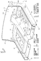
図1には、本実施形態に係る車体下部構造10が斜視図で示されている。また、図2には、図1の2−2線に沿った拡大断面図が示され、図3には、図1の3−3線に沿った拡大断面図が示されている。
FIG. 1 is a perspective view of a
図1に示されるように、車体前部12(エンジンルーム)と車室14とは、ダッシュパネル16(車体客室前壁)によって隔成されている。ダッシュパネル16の上部は、略垂直板状に形成された垂直板部16Aとなっており、ダッシュパネル16の下部は、この垂直板部16Aと一体的に設けられて傾斜板状に形成されたトーボード部16Bとなっている。トーボード部16Bは、車体下方側へ向けて車体後方側に傾斜している。トーボード部16Bの下端部には、車体フロア18の前端部18Aが溶接等で結合されて一体化されている。すなわち、ダッシュパネル16の下部側には、車体フロア18が連接して車体後方側に延びている。車体フロア18は、車室14のフロア面を構成している。
As shown in FIG. 1, the vehicle body front portion 12 (engine room) and the
ダッシュパネル16におけるトーボード部16Bの後面側から車体フロア18にかけての車体幅方向中央部には、トンネル20が設けられている。トンネル20は、車体正面視で車体下方側に開口して略逆U字状に形成され、上壁部20A及び一対の側壁部20Bを備えており、車体前後方向に延在している。一対の側壁部20Bは、上壁部20Aの車体幅方向外側の端部から車体下方側へ向けて車体幅方向外側に傾斜した傾斜壁部とされている。トンネル20の前端部は、本実施形態では、一例として、ダッシュパネル16の一般部と同じ材料でかつ同じ板厚で構成されている。トンネル20の内側には、車体前後方向に延びる排気管56(図2参照)が配設されている。
A
車体フロア18の車体幅方向外側には、車体側部22の骨格部材としての左右一対のロッカ(サイドシルともいう)24が設けられている。ロッカ24は、車体前後方向に延在しており、車体幅方向外側に配置されたロッカアウタ24Aと、車体幅方向内側に配置されたロッカインナ24Bと、を含んで構成されている。ロッカアウタ24A及びロッカインナ24Bは、互いに向き合う側が開放された断面略ハット状に形成され、上下一対のフランジ部同士が溶接で接合されることで、車体前後方向に延在する閉断面を形成している。ロッカインナ24Bの車体幅方向内側の側面には、車体フロア18の車体幅方向外側の端末部18Bが車体上方側に折り曲げられた状態で溶接により接合されている。
A pair of left and right rockers (also referred to as side sills) 24 as skeleton members of the vehicle
ロッカ24の前端部からは車体上方側へ延びるフロントピラー26(Aピラー)が配設されている。フロントピラー26は、車体側部22の骨格部材であり、車体上下方向に延在する閉断面部を含んで構成されている。フロントピラー26の下部は、ダッシュパネル16の車体幅方向外側に配設されている。
A front pillar 26 (A pillar) extending from the front end of the
図4には、車体下部構造10を車体後上方側から斜めに見た状態の模式図が示されている。図4に示されるように、車体前部12における両サイドには、フロントサイドメンバ52が車体前後方向に延在している。フロントサイドメンバ52は、車体前部12において車体正面視で略矩形の閉断面を備えると共に、ダッシュパネル16のトーボード部16Bの下面に沿って傾斜し、さらに車体フロア18の前端部18Aの下面側まで延びている。フロントサイドメンバ52の後部は、車体上方側が開放された断面略ハット状に形成され、左右一対のフランジ部(図示省略)がトーボード部16B及び車体フロア18の前端部18Aの各下面に溶接で接合されている。また、フロントサイドメンバ52の後端部にはアンダリインフォース(図示省略)が連接されている。前記アンダリインフォースは、車体上方側が開放された断面略ハット状に形成され、車体前後方向に延在しており、左右一対のフランジ部が車体フロア18の下面に溶接で接合されている。
FIG. 4 shows a schematic view of the vehicle body
フロントサイドメンバ52の後端部及び前記アンダリインフォースの前端部に対して、トーボード部16B及び車体フロア18を挟んだ上方側には、補強用のアッパメンバ28が配置されている。アッパメンバ28は、車体下方側が開放された断面略ハット状に形成され、車体前後方向に延在しており、左右一対のフランジ部28A(図1参照)が車体フロア18の上面に溶接で接合されている。
A reinforcing
図1に示されるように、トンネル20の車体前後方向中間部とロッカ24の車体前後方向中間部とは、フロアクロスメンバ30によって車体幅方向に連結されている。フロアクロスメンバ30は、一例として、前席着座乗員スペースに対して若干車両後方側に設定されている。フロアクロスメンバ30は、車体側面視で車体下方側が開放された断面略ハット状に形成され、車体幅方向に延在しており、前後一対の前フランジ部30A(図3参照)及び後フランジ部30Bが車体フロア18の上面における車体前後方向中間部に溶接で接合されている。これにより、フロアクロスメンバ30と車体フロア18とで、閉断面部が形成されており、この閉断面部は、フロアクロスメンバ30がトンネル20とロッカ24とを連結する方向に延在している。フロアクロスメンバ30は、上面前端縁において車体幅方向に沿う前側稜線30Lを備えると共に、上面後端縁において車体幅方向に沿う後側稜線30Mを備えている。
As shown in FIG. 1, the vehicle body longitudinal direction intermediate portion of the
フロアクロスメンバ30には、車体幅方向内側の端末部において略逆U字の断面外側に折り曲げられた端末フランジ部30Cが形成されている。この端末フランジ部30Cは、トンネル20の側壁部20Bの外側面に溶接で接合されている。また、フロアクロスメンバ30には、車体幅方向外側の端末部において略逆U字の断面外側に折り曲げられた端末フランジ部30Dが形成されている。端末フランジ部30Dは、ロッカインナ24Bにおける車体幅方向内側の面に溶接で接合されている。
The
また、トンネル20の前端部とロッカ24の前端部とは、ダッシュクロスメンバ32によって車体幅方向に連結されている。より具体的には、ダッシュクロスメンバ32は、トンネル20に対して車体幅方向の左右両側に一対で配置され、トンネル20の側壁部20Bの前端部とロッカ24の前端部とを車体幅方向に架け渡している。このダッシュクロスメンバ32は、アッパメンバ28の前端部と交わっており、車体幅方向内側の端部からアッパメンバ28と交わる部位までは車体幅方向に延在し、アッパメンバ28と交わる部位よりも車体幅方向外側の部位では車体幅方向外側へ向けて車体後方側に湾曲しながら延設されている。
Further, the front end portion of the
ダッシュクロスメンバ32は、延在方向に直交する断面形状が車体前方側ないしは車体幅方向外側が開放された略ハット状に形成され、上下一対の上フランジ部32A及び下フランジ部32Bがダッシュパネル16におけるトーボード部16Bの後面に溶接で接合されている。これにより、ダッシュクロスメンバ32とダッシュパネル16とで閉断面部が形成されており、この閉断面部は、ダッシュクロスメンバ32がトンネル20とロッカ24とを連結する方向に延在している。また、ダッシュクロスメンバ32は、その上面後端縁において車体幅方向に沿う第一稜線としての上側稜線32Lを備えると共に、下面後端縁において車体幅方向に沿う下側稜線32Mを備えている。
The
ダッシュクロスメンバ32の車体幅方向内側の端末部は、トンネル20の側壁部20Bの外側面に突き当てられている。ダッシュクロスメンバ32の車体幅方向内側の端末部には、略逆U字の断面外側に折り曲げられた端末フランジ部32Cが形成されている。端末フランジ部32Cは、トンネル20の側壁部20Bに溶接で接合されている。また、ダッシュクロスメンバ32は、車体幅方向外側の端末部32Dがロッカインナ24Bの前端部に重ね合わせられて溶接で接合されている。
A terminal portion on the inner side in the vehicle body width direction of the
また、図4に示されるように、トンネル20に対して車体幅方向両側かつ車体下方側には、左右一対の床下リインフォースメント34が設けられている。床下リインフォースメント34は、車体平面視で車体前後方向に延在すると共にダッシュパネル16のトーボード部16B及び車体フロア18の各下面に接合されている。
As shown in FIG. 4, a pair of left and right
図2に示されるように、床下リインフォースメント34は、その延在方向に垂直な断面視でダッシュパネル16のトーボード部16Bの側及び車体フロア18(図3参照)の側が開放された断面略U字状の突出部36を備えている。この突出部36の底壁部36Aは、ダッシュパネル16のトーボード部16B及び車体フロア18(図3参照)に対して離間して対向配置されている。
As shown in FIG. 2, the
また、突出部36は、底壁部36Aの車体幅方向内側の端部から立設された内側縦壁部36Bを備えると共に、底壁部36Aの車体幅方向外側の端部から立設された外側縦壁部36Cを備えている。内側縦壁部36Bは、底壁部36Aから離間する方向へ向けて車体幅方向内側に傾斜しており、外側縦壁部36Cは、底壁部36Aから離間する方向へ向けて車体幅方向外側に傾斜している。
The projecting
床下リインフォースメント34は、内側縦壁部36Bの上端部から延長されてトンネル20の側壁部20Bの内側面に重ね合わせられかつ溶接で接合された合わせ部38Aを備えている。また、床下リインフォースメント34は、外側縦壁部36Cの上端部から車体幅方向外側に曲げられて延設された外側フランジ部38Bを備えている。外側フランジ部38Bは、ダッシュパネル16のトーボード部16B及び車体フロア18(図3参照)の各下面に溶接で接合されている。これらにより、床下リインフォースメント34は、ダッシュパネル16のトーボード部16B及び車体フロア18(図3参照)とで、床下リインフォースメント34の延在方向に見て閉断面部を形成している。
The
また、図3に示されるように、床下リインフォースメント34の前部は、トーボード部16Bに沿うように車体上方斜め前方側に曲げられており、突出部36における底壁部36Aの前部は、車体前方側へ向けて車体上方側に傾斜した前端傾斜部36A1とされている。前端傾斜部36A1の前端部(上端部)からはトーボード部16Bの側に立設された前壁部36Dが形成されている。前壁部36Dは、前端傾斜部36A1から離間する方向へ向けて車体上方側に傾斜している。また、床下リインフォースメント34の前端部は、前壁部36Dと前端傾斜部36A1との境界部である上面前端縁において車体幅方向に沿う第三稜線としての前側稜線34Lを備えている。
As shown in FIG. 3, the front portion of the
床下リインフォースメント34は、前壁部36Dの上端部(後端部)から車体上方斜め前方側に曲げられて延設された前フランジ部38Cを備えている。前フランジ部38Cは、ダッシュパネル16のトーボード部16Bの下面(前面)に重ね合わせられ、トーボード部16Bを挟んでダッシュクロスメンバ32の上フランジ部32Aに対向配置されている。そして、床下リインフォースメント34の前フランジ部38C、ダッシュパネル16のトーボード部16B、及びダッシュクロスメンバ32の上フランジ部32Aは、三枚重ねの状態で溶接によりで結合されている。すなわち、床下リインフォースメント34は、前端部がダッシュパネル16のトーボード部16Bを介してダッシュクロスメンバ32に結合されている。
The
一方、床下リインフォースメント34の後部において、突出部36は、底壁部36Aの後端部から車体フロア18の側に立設された後壁部36Eを備えている。後壁部36Eは、底壁部36Aから離間する方向へ向けて車体後方側に傾斜している。床下リインフォースメント34の後端部は、後壁部36Eと底壁部36Aとの境界部である底面後端縁において車体幅方向に沿う後側稜線34Mを備えている。床下リインフォースメント34の後側稜線34Mは、車体上面視でフロアクロスメンバ30の後側稜線30Mと重なる位置に設定されている。
On the other hand, at the rear part of the
また、床下リインフォースメント34は、後壁部36Eの上端部から車体後方側に曲げられて延設された後フランジ部38Dを備えている。後フランジ部38Dは、車体フロア18の下面に重ね合わせられ、車体フロア18を挟んでフロアクロスメンバ30の後フランジ部30Bに対向配置されている。そして、床下リインフォースメント34の後フランジ部38D、車体フロア18、及びフロアクロスメンバ30の後フランジ部30Bは、三枚重ねの状態で溶接によりで結合されている。すなわち、床下リインフォースメント34は、後端部が車体フロア18を介してフロアクロスメンバ30に結合されている。
The
以上により、床下リインフォースメント34は、ダッシュパネル16のトーボード部16B及び車体フロア18とで、車体側面視で閉断面部を形成している。
As described above, the
図2及び図4に示されるように、トンネル20の前端部に対して車室14側とは反対側には、車体幅方向に延在する床下ブレース40が設けられている。床下ブレース40は、その車体幅方向の両端部がトンネル20の前端部よりも車体幅方向外側に設定されかつトーボード部16Bに床下リインフォースメント34を介して固定されている。すなわち、トンネル20の前端部は、床下リインフォースメント34及び床下ブレース40によって補強されている。そして、ダッシュパネル16のトーボード部16Bを挟んでダッシュクロスメンバ32の車体幅方向内側の端部の対向位置に、床下ブレース40の車体幅方向の端部が設定されている。換言すれば、本実施形態では、床下ブレース40の車体幅方向の両端部は、ダッシュパネル16のトーボード部16Bを挟んでダッシュクロスメンバ32の車体幅方向内側の端部の対向位置に設定されている。以下、床下ブレース40について詳細に説明する。
As shown in FIGS. 2 and 4, an
図3に示されるように、床下ブレース40は、車体側面視で車体前方斜め下方側が開放された断面略ハット状の第一パネル42と、第一パネル42の開放側を塞ぐ平板状の第二パネル48と、が接合された補強部材とされている。第一パネル42は、車体側面視で車体前下方側が開放された断面略U字状の突出部44を備え、突出部44は、上壁部44Aの後端部と下壁部44Cの後端部とが傾斜壁部44Bによって連結されている。傾斜壁部44Bは、車体上方側へ向けて車体前方側に傾斜している。
As shown in FIG. 3, the
第一パネル42は、上壁部44Aと傾斜壁部44Bとの境界部に車体幅方向に沿う第二稜線としての上側稜線42Lを備えると共に、下壁部44Cと傾斜壁部44Bとの境界部に車体幅方向に沿う下側稜線42Mを備えている。上側稜線42Lの車体幅方向の両端部は、床下ブレース40の車体幅方向の端部がダッシュパネル16を挟んでダッシュクロスメンバ32の車体幅方向内側の端部に対向する方向に見て、ダッシュクロスメンバ32の上側稜線32Lと重なる位置に設定されている。
The
また、第一パネル42は、上壁部44Aの前端部から車体上方斜め前方側に延出された上フランジ部46Aと、下壁部44Cの前端部から車体下方斜め後方側に延出された下フランジ部46Bと、を備えている。床下ブレース40は、第一パネル42の上フランジ部46Aと第二パネル48の上端部とが溶接で接合されると共に、第一パネル42の下フランジ部46Bと第二パネル48の下端部とが溶接で接合されることで、車体幅方向に延在する閉断面部を備えている。
Further, the
また、図2に示されるように、第一パネル42は、突出部44の車体幅方向両端部における開口端から互いに離反する方向に張り出した左右一対のフランジ部46C、46Dを備えている。そして、床下ブレース40は、第一パネル42の左右一対のフランジ部46C、46Dが第二パネル48の左右両端部と溶接で接合されることで、図2の断面に垂直な方向に延在する閉断面部を備えている。
Further, as shown in FIG. 2, the
図3に示されるように、床下ブレース40における第一パネル42の傾斜壁部44Bは、その車体幅方向の両端部が床下リインフォースメント34の前端傾斜部36A1に重ね合わせられかつボルト50A及びウエルドナット50Bで締結されている。これにより、床下ブレース40における車体幅方向の両端部は、床下リインフォースメント34に結合されている。そして、床下ブレース40の車体幅方向の端部がダッシュパネル16を挟んでダッシュクロスメンバ32の車体幅方向内側の端部に対向する方向に見て、前述した床下リインフォースメント34の前側稜線34Lは、ダッシュクロスメンバ32の上側稜線32L及び床下ブレース40の上側稜線42Lと重なる位置に設定されている。
As shown in FIG. 3, the inclined wall portion 44B of the
(実施形態の作用・効果)
次に、上記実施形態の作用及び効果について説明する。
(Operation and effect of the embodiment)
Next, the operation and effect of the above embodiment will be described.
図4に示されるように、微小ラップ衝突(フロントサイドメンバ52の車体幅方向外側に衝突荷重が入力される形態の前面衝突)時に、前輪54がロッカ24の前端部に車体幅方向外側斜め前方側から衝突する場合がある。このような場合、ロッカ24の前端部には、車体幅方向内側へ向けた荷重F(横力)が入力され、ロッカ24を外凸折れさせようとする(ロッカ24の車体前後方向中間部を車体幅方向外側へ突出させるように折れ曲げようする)曲げモーメントが作用する。
As shown in FIG. 4, in the case of a minute lap collision (frontal collision in which a collision load is input to the outer side of the
このとき、本実施形態によれば、左右一対のダッシュクロスメンバ32のうちの一方側のダッシュクロスメンバ32に対して車体幅方向内側へ向けた荷重Fが入力されても、床下ブレース40が突っ張り支持してトンネル20の変形を抑えると共に、荷重Fが床下ブレース40を介して他方側のダッシュクロスメンバ32に伝達される。そして、トンネル20の上壁部20A(図2参照)を車体上方側に凸状に曲げるような変形が抑えられることで、ダッシュクロスメンバ32で大きな反力を発生させることができるので、ロッカ24の外凸折れが抑えられる。
At this time, according to the present embodiment, even if a load F directed inward in the vehicle body width direction is input to one
ここで、対比構造と比較しながら補足説明する。例えば、ダッシュクロスメンバの左右両端部がロッカ(24)に接合されると共にダッシュクロスメンバの車体幅方向中央部が図2に二点鎖線60で示されるように、トンネル(20)の上部を跨ぐ(回り込む)ような対比構造では、一方側のダッシュクロスメンバに対して車体幅方向内側へ向けた荷重が入力されても、トンネル(20)の変形は抑えられる。このため、前記対比構造でも、ダッシュクロスメンバで大きな反力を発生させることができ、ロッカ(24)の外凸折れを抑えることができる。
Here, a supplementary explanation will be given while comparing with the contrast structure. For example, the left and right end portions of the dash cross member are joined to the rocker (24) and the center portion of the dash cross member in the vehicle width direction straddles the upper portion of the tunnel (20) as indicated by a two-
しかしながら、前記対比構造の場合、ダッシュクロスメンバがトンネル(20)の上部を跨ぐため、車室(14)の空間が狭められる。特に、前記対比構造では、トンネル(20)の側方側近傍の空間がダッシュクロスメンバの一部によって大きく狭められてしまうので、アクセルペダル58の操作スペース(操作軌跡)とダッシュクロスメンバの配置位置とを重ならないように設定することができない場合がある。
However, in the case of the contrast structure, since the dash cross member straddles the upper part of the tunnel (20), the space of the passenger compartment (14) is narrowed. In particular, in the contrast structure, the space near the side of the tunnel (20) is greatly narrowed by a part of the dash cross member. Therefore, the operation space (operation locus) of the
これに対して、本実施形態では、ダッシュクロスメンバ32がトンネル20の上部を跨がず、床下ブレース40がトンネル20の前端部に対して車室14側とは反対側に設けられているため、車室14の空間を大きく設定することができ、アクセルペダル58の操作スペースとダッシュクロスメンバ32の配置位置とを重ならないように設定することが容易にできる。すなわち、パッケージ(部品等のレイアウト)の設定を良好にすることができる。なお、図2では、踏み込まれたアクセルペダル58を二点鎖線で示している。
On the other hand, in this embodiment, the
また、本実施形態では、図3に示される床下ブレース40の上側稜線42Lは、車体幅方向に沿い、上側稜線42Lの車体幅方向の両端部は、床下ブレース40の車体幅方向の端部がダッシュパネル16を挟んでダッシュクロスメンバ32の車体幅方向内側の端部に対向する方向に見て、ダッシュクロスメンバ32の上側稜線32Lと重なる位置に設定されている。このため、衝突時に一方側のダッシュクロスメンバ32に対して車体幅方向内側へ向けた荷重が入力された場合、当該荷重が車体幅方向に効率良く伝達される。
Further, in the present embodiment, the
また、本実施形態では、図2に示される左右一対の床下リインフォースメント34は、ダッシュパネル16のトーボード部16B及び車体フロア18(図1参照)に接合されており、床下ブレース40における車体幅方向の両端部は、床下リインフォースメント34に結合されている。このため、衝突時に図4に示されるダッシュクロスメンバ32に対して荷重Fが入力された場合に、当該荷重の一部が床下リインフォースメント34に沿って車体後方側に伝達される。
In the present embodiment, the pair of left and right
また、本実施形態では、図3に示される床下リインフォースメント34の前端部における前側稜線34Lは、車体幅方向に沿い、床下ブレース40の車体幅方向の端部がダッシュパネル16を挟んでダッシュクロスメンバ32の車体幅方向内側の端部に対向する方向に見て、ダッシュクロスメンバ32の上側稜線32L及び床下ブレース40の上側稜線42Lと重なる位置に設定されている。このため、衝突時にダッシュクロスメンバ32に対して荷重が入力された場合、当該荷重が車体後方側及び車体幅方向に効率良く伝達される。
Further, in the present embodiment, the
また、本実施形態では、図4に示されるように、床下リインフォースメント34は、前端部がダッシュパネル16を介してダッシュクロスメンバ32に結合されると共に、後端部が車体フロア18を介してフロアクロスメンバ30に結合されている。このため、衝突時にダッシュクロスメンバ32に対して荷重が入力された場合、ダッシュクロスメンバ32は床下リインフォースメント34を介してフロアクロスメンバ30によって支持されるので、荷重が効率良く伝達される。
In the present embodiment, as shown in FIG. 4, the
以上説明したように、本実施形態に係る車体下部構造10によれば、図1〜図3等に示されるように車室14の空間が狭まるのを抑えながら、ダッシュクロスメンバ32への荷重入力時にトンネル20の変形を抑えて効率良く荷重を伝達させることができる。
As described above, according to the vehicle body
(実施形態の補足説明)
なお、本発明の実施形態ではない参考例として、ダッシュパネル(16)の下部後面に接合されたダッシュクロスメンバは、トンネル(20)の側壁部(20B)の前端部と、車体側部(22)の骨格部材としてのフロントピラー(26)等のような他の骨格部材と、を車体幅方向に架け渡すものであってもよい。
(Supplementary explanation of the embodiment)
As a reference example that is not an embodiment of the present invention, the dash cross member joined to the lower rear surface of the dash panel (16) includes the front end portion of the side wall portion (20B) of the tunnel (20) and the vehicle body side portion (22). ) And other skeleton members such as the front pillar (26) as a skeleton member may be bridged in the vehicle body width direction.
また、上記実施形態の変形例として、トンネル(20)の前端部は、上記実施形態の構成に代えて、ダッシュパネル(16)の一般部よりも、高強度の材料で形成された部材又は板厚が厚く設定された部材で構成されてもよい。 Further, as a modification of the above embodiment, the front end portion of the tunnel (20) is a member or plate formed of a material having higher strength than the general portion of the dash panel (16) instead of the configuration of the above embodiment. You may be comprised with the member set thickly.
また、上記実施形態の変形例として、床下ブレース(40)の車体幅方向の端部がダッシュパネル(16)を挟んでダッシュクロスメンバ(32)の車体幅方向内側の端部に対向する方向に見て、床下ブレース(40)の上側稜線(42L)における車体幅方向の端部がダッシュクロスメンバ(32)の上側稜線(32L)と重ならない位置に設定された構成も採り得る。 As a modification of the above embodiment, the end of the underfloor brace (40) in the vehicle width direction faces the end of the dash cross member (32) on the inner side of the dash cross member (32) across the dash panel (16). look, can take also the configuration set on the upper edge line (32L) and does not overlap the position of the end portion Hurghada Tsu Gerhard cross member of the vehicle body width direction (32) of the upper edge line (42L) of the floor brace (40).
また、上記実施形態の変形例として、床下リインフォースメント34が配置されず、床下ブレース(40)の車体幅方向の両端部がダッシュパネル(16)を挟んで左右一対のダッシュクロスメンバ(32)の車体幅方向内側の端部の対向位置に設定されかつダッシュパネル(16)に直接ボルト締結により固定されてもよい。
Further, as a modification of the above embodiment, the
また、上記実施形態の変形例として、床下ブレース(40)の車体幅方向の端部がダッシュパネル(16)を挟んでダッシュクロスメンバ(32)の車体幅方向内側の端部に対向する方向に見て、床下リインフォースメント(34)の前側稜線(34L)がダッシュクロスメンバ(32)の上側稜線(32L)及び床下ブレース(40)の上側稜線(42L)のいずれか又は両方と重ならない位置に設定された構成も採り得る。 As a modification of the above embodiment, the end of the underfloor brace (40) in the vehicle width direction faces the end of the dash cross member (32) on the inner side of the dash cross member (32) across the dash panel (16). look, does not overlap with either or both of the upper edge line (42L) of the upper edge line (32L) and underfloor braces (40) of the front edge line (34L) Hurghada Tsu Gerhard cross member (32) of the floor reinforcement (34) A configuration set in the position can also be adopted.
また、上記実施形態の変形例として、床下リインフォースメント(34)の前端部がダッシュパネル(16)を介してダッシュクロスメンバ(32)に結合されていない構成も採り得る。また、床下リインフォースメント(34)の後端部が車体フロア(18)を介してフロアクロスメンバ(30)に結合されていない構成も採り得る。 As a modification of the above embodiment, a configuration in which the front end portion of the underfloor reinforcement (34) is not coupled to the dash cross member (32) via the dash panel (16) may be employed. Moreover, the structure which the rear-end part of underfloor reinforcement (34) is not couple | bonded with the floor cross member (30) via the vehicle body floor (18) can also be taken.
また、上記実施形態では、図2及び図3に示されるように、床下ブレース40は、第一パネル42と第二パネル48とが接合された部材とされているが、床下ブレースは、例えば、筒状部材や板状部材で構成された床下ブレース等のような他の床下ブレースとすることも可能である。
Moreover, in the said embodiment, as FIG.2 and FIG.3 shows, although the
また、上記実施形態では、ダッシュクロスメンバ32が左右一対設けられているが、ダッシュクロスメンバは、例えば、左右のどちらか片方のみ(すなわち、ダッシュパネルの下部後面における車体左側のみ又は車体右側のみ)に設けられてもよい。
In the above embodiment, the pair of left and right
なお、上記実施形態及び上述の複数の変形例は、適宜組み合わされて実施可能である。 In addition, the said embodiment and the above-mentioned some modification can be implemented combining suitably.
以上、本発明の一例について説明したが、本発明は、上記に限定されるものでなく、上記以外にも、その主旨を逸脱しない範囲内にいて種々変形して実施可能であることは勿論である。 Although an example of the present invention has been described above, the present invention is not limited to the above, and it is needless to say that various modifications can be made without departing from the scope of the present invention. is there.
10 車体下部構造
12 車体前部
14 車室
16 ダッシュパネル
18 車体フロア
20 トンネル
20B トンネルの側壁部
22 車体側部
24 ロッカ
30 フロアクロスメンバ
32 ダッシュクロスメンバ
32L 上側稜線(第一稜線)
34 床下リインフォースメント
34L 前側稜線(第三稜線)
40 床下ブレース
42L 上側稜線(第二稜線)
10 vehicle body
34
40
Claims (5)
前記ダッシュパネルの下部後面側から前記車体フロアにかけての車体幅方向中央部に設けられ、車体前後方向に延在するトンネルと、
車体側部において車体前後方向に延在して前記車体フロアの車体幅方向外側に設けられたロッカと、
前記ダッシュパネルの下部後面に接合され、前記トンネルの側壁部の前端部の下側部分と、前記ロッカの前端部と、を車体幅方向に架け渡すダッシュクロスメンバと、
前記トンネルの前端部に対して車室側とは反対側に設けられて車体幅方向に延在すると共に、車体幅方向の両端部が前記トンネルの前端部よりも車体幅方向外側に設定されかつ前記ダッシュパネルに直接又は他部材を介して固定され、前記ダッシュパネルを挟んで前記ダッシュクロスメンバの車体幅方向内側の端部の対向位置に、車体幅方向の端部が設定された床下ブレースと、
を有し、
前記ダッシュクロスメンバは、車体幅方向に沿う第一稜線を備え、
前記床下ブレースは、車体幅方向に沿う第二稜線を備え、前記第二稜線の車体幅方向の端部は、前記床下ブレースの車体幅方向の端部が前記ダッシュパネルを挟んで前記ダッシュクロスメンバの車体幅方向内側の端部に対向する方向に見て前記第一稜線と重なる位置に設定されている、車体下部構造。 A vehicle body floor connected to the lower side of the dash panel that separates the vehicle body front portion and the vehicle compartment and extending to the vehicle body rear side;
A tunnel provided in the vehicle body width direction center portion from the lower rear surface side of the dash panel to the vehicle body floor, and extending in the vehicle body longitudinal direction;
A rocker that extends in the longitudinal direction of the vehicle body at the vehicle body side and is provided outside the vehicle body width direction of the vehicle body floor;
A dash cross member that is joined to the lower rear surface of the dash panel and bridges the lower part of the front end of the side wall of the tunnel and the front end of the rocker in the vehicle body width direction;
It is provided on the opposite side to the passenger compartment side with respect to the front end portion of the tunnel and extends in the vehicle body width direction, and both end portions in the vehicle body width direction are set outside the vehicle body width direction from the front end portion of the tunnel, and An underfloor brace that is fixed to the dash panel directly or via another member, and has an end in the vehicle body width direction at a position opposite to the inner end of the dash cross member in the vehicle width direction across the dash panel. ,
I have a,
The dash cross member includes a first ridge line along the vehicle body width direction,
The underfloor brace includes a second ridge line along a vehicle body width direction, and an end portion of the second ridge line in the vehicle body width direction is configured such that an end portion of the underfloor brace in the vehicle body width direction sandwiches the dash panel. A vehicle body lower structure , which is set at a position overlapping with the first ridge line when viewed in a direction facing the inner end of the vehicle body width direction .
前記ダッシュパネルの下部後面側から前記車体フロアにかけての車体幅方向中央部に設けられ、車体前後方向に延在するトンネルと、
車体側部において車体前後方向に延在して前記車体フロアの車体幅方向外側に設けられたロッカと、
前記ダッシュパネルの下部後面に接合され、前記トンネルの側壁部の前端部の下側部分と、前記ロッカの前端部と、を車体幅方向に架け渡すダッシュクロスメンバと、
前記トンネルの前端部に対して車室側とは反対側に設けられて車体幅方向に延在すると共に、車体幅方向の両端部が前記トンネルの前端部よりも車体幅方向外側に設定されかつ前記ダッシュパネルに直接又は他部材を介して固定され、前記ダッシュパネルを挟んで前記ダッシュクロスメンバの車体幅方向内側の端部の対向位置に、車体幅方向の端部が設定された床下ブレースと、
を有し、
前記トンネルに対して車体幅方向両側かつ車体下方側に左右一対の床下リインフォースメントが設けられ、前記床下リインフォースメントは、車体平面視で車体前後方向に延在すると共に前記ダッシュパネルの下部及び前記車体フロアに接合されており、
前記床下ブレースにおける車体幅方向の両端部は、前記床下リインフォースメントに結合されている、車体下部構造。 A vehicle body floor connected to the lower side of the dash panel that separates the vehicle body front portion and the vehicle compartment and extending to the vehicle body rear side;
A tunnel provided in the vehicle body width direction center portion from the lower rear surface side of the dash panel to the vehicle body floor, and extending in the vehicle body longitudinal direction;
A rocker that extends in the longitudinal direction of the vehicle body at the vehicle body side and is provided outside the vehicle body width direction of the vehicle body floor;
A dash cross member that is joined to the lower rear surface of the dash panel and bridges the lower part of the front end of the side wall of the tunnel and the front end of the rocker in the vehicle body width direction;
It is provided on the opposite side to the passenger compartment side with respect to the front end portion of the tunnel and extends in the vehicle body width direction, and both end portions in the vehicle body width direction are set outside the vehicle body width direction from the front end portion of the tunnel, and An underfloor brace that is fixed to the dash panel directly or via another member, and has an end in the vehicle body width direction at a position opposite to the inner end of the dash cross member in the vehicle width direction across the dash panel. ,
I have a,
A pair of left and right underfloor reinforcements are provided on both sides in the vehicle body width direction and on the vehicle body lower side with respect to the tunnel, and the underfloor reinforcement extends in the vehicle front-rear direction in a plan view of the vehicle body and extends below the dash panel and the vehicle body. Joined to the floor,
A vehicle body lower structure in which both end portions in the vehicle body width direction of the underfloor brace are coupled to the underfloor reinforcement .
前記床下ブレースにおける車体幅方向の両端部は、前記床下リインフォースメントに結合されている、請求項1記載の車体下部構造。 A pair of left and right underfloor reinforcements are provided on both sides in the vehicle body width direction and on the vehicle body lower side with respect to the tunnel, and the underfloor reinforcement extends in the vehicle front-rear direction in a plan view of the vehicle body and extends below the dash panel and the vehicle body. Joined to the floor,
Both end portions of the vehicle body width direction of the underfloor brace, the coupled under the floor reinforcement, underbody structure of claim 1 Symbol placement.
前記床下リインフォースメントは、前端部が前記ダッシュパネルを介して前記ダッシュクロスメンバに結合されると共に、後端部が前記車体フロアを介して前記フロアクロスメンバに結合されている、請求項2〜請求項4のいずれか1項に記載の車体下部構造。 On the upper surface of the vehicle body floor, a floor cross member extending in the vehicle body width direction is joined at the vehicle body longitudinal direction intermediate portion,
The underfloor reinforcements, along with the front end portion is coupled to said dash cross member via the dash panel, the rear end portion is coupled to the floor cross member through the vehicle floor, Claim 2 wherein Item 5. The vehicle body lower structure according to any one of Items 4 to 4.
Priority Applications (3)
| Application Number | Priority Date | Filing Date | Title |
|---|---|---|---|
| JP2014026744A JP6079662B2 (en) | 2014-02-14 | 2014-02-14 | Lower body structure |
| US14/616,951 US9238485B2 (en) | 2014-02-14 | 2015-02-09 | Vehicle body lower structure |
| CN201510071173.7A CN104843084A (en) | 2014-02-14 | 2015-02-10 | Vehicle body lower structure |
Applications Claiming Priority (1)
| Application Number | Priority Date | Filing Date | Title |
|---|---|---|---|
| JP2014026744A JP6079662B2 (en) | 2014-02-14 | 2014-02-14 | Lower body structure |
Publications (2)
| Publication Number | Publication Date |
|---|---|
| JP2015151018A JP2015151018A (en) | 2015-08-24 |
| JP6079662B2 true JP6079662B2 (en) | 2017-02-15 |
Family
ID=53797410
Family Applications (1)
| Application Number | Title | Priority Date | Filing Date |
|---|---|---|---|
| JP2014026744A Expired - Fee Related JP6079662B2 (en) | 2014-02-14 | 2014-02-14 | Lower body structure |
Country Status (3)
| Country | Link |
|---|---|
| US (1) | US9238485B2 (en) |
| JP (1) | JP6079662B2 (en) |
| CN (1) | CN104843084A (en) |
Families Citing this family (24)
| Publication number | Priority date | Publication date | Assignee | Title |
|---|---|---|---|---|
| CN104349971A (en) * | 2012-06-08 | 2015-02-11 | 本田技研工业株式会社 | Fibre-reinforced plastic (FRP) cabin for vehicle |
| JP6011583B2 (en) * | 2014-07-04 | 2016-10-19 | トヨタ自動車株式会社 | Vehicle lower structure |
| BR112017012652A2 (en) * | 2014-12-22 | 2017-12-26 | Nippon Steel & Sumitomo Metal Corp | structural member |
| JP6222122B2 (en) * | 2015-01-21 | 2017-11-01 | マツダ株式会社 | Lower body structure of the vehicle |
| JP6197841B2 (en) * | 2015-08-24 | 2017-09-20 | マツダ株式会社 | Vehicle body structure |
| JP6311679B2 (en) * | 2015-08-25 | 2018-04-18 | トヨタ自動車株式会社 | Vehicle lower structure |
| JP6337860B2 (en) * | 2015-09-15 | 2018-06-06 | トヨタ自動車株式会社 | Vehicle skeleton structure |
| JP6269634B2 (en) * | 2015-10-30 | 2018-01-31 | トヨタ自動車株式会社 | Vehicle lower structure |
| JP6237749B2 (en) * | 2015-11-11 | 2017-11-29 | マツダ株式会社 | Rear subframe structure |
| FR3052427B1 (en) * | 2016-06-13 | 2018-07-06 | Peugeot Citroen Automobiles Sa | ASSEMBLY OF REAR PANEL AND ITS LINING WITH INTEGRATED REINFORCING ELEMENT |
| JP2019177705A (en) | 2016-07-11 | 2019-10-17 | 本田技研工業株式会社 | Vehicle body substructure |
| US9981698B2 (en) * | 2016-09-07 | 2018-05-29 | Thunder Power New Energy Vehicle Development Company Limited | Vehicle tunnel floor structure |
| US20180065461A1 (en) * | 2016-09-07 | 2018-03-08 | Thunder Power New Energy Vehicle Development Company Limited | Cross member in the floor with special geometry for mounting the battery pack |
| KR101875660B1 (en) * | 2016-11-18 | 2018-07-06 | 현대자동차 주식회사 | Transmission mounting vehicle body structure for rear wheel driving vehicle |
| JP6662281B2 (en) * | 2016-12-20 | 2020-03-11 | 三菱自動車工業株式会社 | Body structure |
| CN106895109A (en) * | 2017-04-07 | 2017-06-27 | 安徽宏祥工业循环经济开发有限公司 | Bridge-type crossbeam assembly with shock detection |
| JP6575015B2 (en) * | 2017-07-07 | 2019-09-18 | 本田技研工業株式会社 | Body structure |
| JP6532513B2 (en) * | 2017-09-15 | 2019-06-19 | 本田技研工業株式会社 | Body structure |
| CN107554623B (en) * | 2017-09-18 | 2020-03-10 | 芜湖金智王机械设备有限公司 | Automobile bottom plate structure |
| JP7095307B2 (en) * | 2018-02-23 | 2022-07-05 | トヨタ自動車株式会社 | Vehicle undercarriage |
| JP6881395B2 (en) * | 2018-06-15 | 2021-06-02 | マツダ株式会社 | Lower body structure |
| JP7035848B2 (en) * | 2018-06-27 | 2022-03-15 | トヨタ自動車株式会社 | Vehicle lower body structure |
| JP7372272B2 (en) * | 2021-01-26 | 2023-10-31 | トヨタ自動車株式会社 | vehicle |
| FR3132493A1 (en) * | 2022-02-04 | 2023-08-11 | Psa Automobiles Sa | Apron side cross member for frontal impact. |
Family Cites Families (14)
| Publication number | Priority date | Publication date | Assignee | Title |
|---|---|---|---|---|
| JPS6428379U (en) * | 1987-08-13 | 1989-02-20 | ||
| JPH0625414Y2 (en) * | 1987-09-29 | 1994-07-06 | 三菱自動車工業株式会社 | Front body joint structure for automobile |
| US6679546B2 (en) * | 2001-06-12 | 2004-01-20 | Mazda Motor Corporation | Front body structure of vehicle |
| JP4872163B2 (en) | 2001-06-12 | 2012-02-08 | マツダ株式会社 | Front body structure of the vehicle |
| JP2005206107A (en) * | 2004-01-26 | 2005-08-04 | Toyota Motor Corp | Vehicle body front structure |
| JP2007131260A (en) * | 2005-11-14 | 2007-05-31 | Suzuki Motor Corp | Dash panel reinforcing structure of vehicle |
| JP4752471B2 (en) | 2005-12-01 | 2011-08-17 | マツダ株式会社 | Vehicle body structure at the bottom of the vehicle |
| JP4304529B2 (en) * | 2006-08-04 | 2009-07-29 | トヨタ自動車株式会社 | Undercarriage of the vehicle |
| JP4825640B2 (en) * | 2006-11-10 | 2011-11-30 | 本田技研工業株式会社 | Auto body structure |
| JP2009286181A (en) * | 2008-05-27 | 2009-12-10 | Toyota Motor Corp | Vehicle body skeleton structure |
| JP2010228731A (en) | 2009-03-30 | 2010-10-14 | Suzuki Motor Corp | Underfloor structure for vehicle |
| JP5280550B2 (en) * | 2009-12-16 | 2013-09-04 | 本田技研工業株式会社 | Body panel joint structure |
| US8485591B2 (en) * | 2010-05-10 | 2013-07-16 | Honda Motor Co., Ltd. | Front vehicle body structure |
| JP5862214B2 (en) * | 2011-11-10 | 2016-02-16 | スズキ株式会社 | Mounting structure for vehicle seat |
-
2014
- 2014-02-14 JP JP2014026744A patent/JP6079662B2/en not_active Expired - Fee Related
-
2015
- 2015-02-09 US US14/616,951 patent/US9238485B2/en not_active Expired - Fee Related
- 2015-02-10 CN CN201510071173.7A patent/CN104843084A/en active Pending
Also Published As
| Publication number | Publication date |
|---|---|
| US9238485B2 (en) | 2016-01-19 |
| US20150232127A1 (en) | 2015-08-20 |
| JP2015151018A (en) | 2015-08-24 |
| CN104843084A (en) | 2015-08-19 |
Similar Documents
| Publication | Publication Date | Title |
|---|---|---|
| JP6079662B2 (en) | Lower body structure | |
| JP5924331B2 (en) | Lower body structure | |
| JP5907147B2 (en) | Lower body structure | |
| JP4283780B2 (en) | Body floor structure | |
| JP4010169B2 (en) | Body structure | |
| JP6449562B2 (en) | Vehicle frame structure | |
| JP6156258B2 (en) | Vehicle front structure | |
| JP5999134B2 (en) | Vehicle front structure | |
| JP4930016B2 (en) | Auto body front structure | |
| JP2006199132A (en) | Vehicle body lower side part structure | |
| JP2017114411A (en) | Vehicle body rear part structure | |
| JP2016037072A (en) | Vehicle lower structure | |
| JP2010125870A (en) | Lower vehicle body structure | |
| JP5014476B2 (en) | Car side sill structure | |
| JP2009286331A (en) | Vehicle body skeleton structure | |
| JP6176086B2 (en) | Lower body structure | |
| JP6090181B2 (en) | Lower body structure | |
| JP6569705B2 (en) | Vehicle frame structure | |
| JP5202571B2 (en) | Car floor structure | |
| WO2020110469A1 (en) | Vehicle body side part structure | |
| JP6186755B2 (en) | Body structure | |
| JP6166789B2 (en) | Car body rear structure | |
| JP5359235B2 (en) | Body front structure | |
| JP7228133B2 (en) | Vehicle floor reinforcing structure | |
| JP5853013B2 (en) | Car body rear structure and method of assembling car body rear structure |
Legal Events
| Date | Code | Title | Description |
|---|---|---|---|
| A621 | Written request for application examination |
Free format text: JAPANESE INTERMEDIATE CODE: A621 Effective date: 20150525 |
|
| A977 | Report on retrieval |
Free format text: JAPANESE INTERMEDIATE CODE: A971007 Effective date: 20151225 |
|
| A131 | Notification of reasons for refusal |
Free format text: JAPANESE INTERMEDIATE CODE: A131 Effective date: 20160105 |
|
| A521 | Written amendment |
Free format text: JAPANESE INTERMEDIATE CODE: A523 Effective date: 20160303 |
|
| A131 | Notification of reasons for refusal |
Free format text: JAPANESE INTERMEDIATE CODE: A131 Effective date: 20160816 |
|
| A521 | Written amendment |
Free format text: JAPANESE INTERMEDIATE CODE: A523 Effective date: 20161005 |
|
| TRDD | Decision of grant or rejection written | ||
| A01 | Written decision to grant a patent or to grant a registration (utility model) |
Free format text: JAPANESE INTERMEDIATE CODE: A01 Effective date: 20161220 |
|
| A61 | First payment of annual fees (during grant procedure) |
Free format text: JAPANESE INTERMEDIATE CODE: A61 Effective date: 20170102 |
|
| R151 | Written notification of patent or utility model registration |
Ref document number: 6079662 Country of ref document: JP Free format text: JAPANESE INTERMEDIATE CODE: R151 |
|
| LAPS | Cancellation because of no payment of annual fees |