JP6077573B2 - Information processing apparatus, control method thereof, and control program - Google Patents
Information processing apparatus, control method thereof, and control program Download PDFInfo
- Publication number
- JP6077573B2 JP6077573B2 JP2015006035A JP2015006035A JP6077573B2 JP 6077573 B2 JP6077573 B2 JP 6077573B2 JP 2015006035 A JP2015006035 A JP 2015006035A JP 2015006035 A JP2015006035 A JP 2015006035A JP 6077573 B2 JP6077573 B2 JP 6077573B2
- Authority
- JP
- Japan
- Prior art keywords
- display
- mode
- unit
- control unit
- information processing
- Prior art date
- Legal status (The legal status is an assumption and is not a legal conclusion. Google has not performed a legal analysis and makes no representation as to the accuracy of the status listed.)
- Expired - Fee Related
Links
Images


Landscapes
- User Interface Of Digital Computer (AREA)
Description
本発明は、画面内の表示をスクロールさせるタッチ操作を受け付けるタッチパッドを備えた情報処理装置に関する。 The present invention relates to an information processing apparatus including a touch pad that receives a touch operation for scrolling a display in a screen.
従来、表示部内の表示をスクロールさせるタッチ操作を受け付ける情報処理装置が知られている。そのような情報処理装置の一例が、特許文献1に記載されている。具体的には、特許文献1に記載の座標入力機器は、入力操作面(表示部)内にスクロール領域を設定する。ユーザは、入力操作面のスクロール領域上に接触させた指を、該スクロール領域が延伸する方向に滑らせることによって、入力操作面内の表示をスクロールさせることができる。
Conventionally, an information processing apparatus that accepts a touch operation for scrolling a display in a display unit is known. An example of such an information processing apparatus is described in
しかしながら、特許文献1に記載の上記座標入力機器は、表示を上下方向にスクロールする操作を受け付けるスクロール領域と、表示を左右方向にスクロールする操作を受け付ける他のスクロール領域とを設定する。そのため、上記座標入力機器のユーザは、表示を斜め方向にスクロールしたい場合、まず、一方のスクロール領域に指を接触させて、表示を上下方向にスクロールさせる一段回目のタッチ操作を行う。次に、ユーザは、他方のスクロール領域に指を接触させて、表示を左右方向にスクロールさせる二段階目のタッチ操作を行う。このように、ユーザは、表示を斜め方向にスクロールするために、手間のかかる二段階のタッチ操作を行う必要がある。
However, the coordinate input device described in
本発明は、上記の課題に鑑みてなされたものであり、その目的は、ユーザが一段階のタッチ操作で表示部の表示を斜め方向にスクロールさせることができる情報処理装置を提供することにある。 The present invention has been made in view of the above problems, and an object of the present invention is to provide an information processing apparatus that allows the user to scroll the display on the display unit in an oblique direction by a one-step touch operation. .
上記の課題を解決するために、本発明の一態様に係る情報処理装置は、表示部と、近接または接触する物体を検出する平面状の検出領域を上記表示部の表示領域とは異なる位置に有する物体検出部と、上記物体検出部が上記物体を検出した位置を示す位置情報を取得する位置情報取得部とを備えた情報処理装置であって、上記表示部の表示領域の座標系と上記物体検出部の検出領域の座標系とが対応付けられており、上記位置情報取得部が、上記検出領域の座標系の座標軸と交わる方向への上記物体の斜め移動を検出した場合、上記検出領域の座標系における上記物体の斜め移動の方向および量に対応する上記表示領域の座標系における方向および量によって、上記表示部の表示を上記表示領域の座標系において斜め移動させる表示制御部をさらに備えている。 In order to solve the above-described problem, an information processing device according to one embodiment of the present invention has a display portion and a planar detection region that detects an object that is close or in contact with the display portion at a position different from the display region of the display portion. An information processing apparatus comprising: an object detection unit having a position information acquisition unit that acquires position information indicating a position where the object detection unit has detected the object; and a coordinate system of a display area of the display unit and the position information acquisition unit When the coordinate system of the detection area of the object detection unit is associated and the position information acquisition unit detects an oblique movement of the object in a direction intersecting with the coordinate axis of the coordinate system of the detection area, the detection area A display control unit for moving the display of the display unit obliquely in the coordinate system of the display region according to the direction and amount of the display region in the coordinate system corresponding to the direction and amount of the oblique movement of the object in the coordinate system of It is provided in La.
また、上記の課題を解決するために、本発明の一態様に係る制御方法は、表示部と、近接または接触する物体を検出する平面状の検出領域を上記表示部の表示領域とは異なる位置に有する物体検出部とを備えた情報処理装置の制御方法であって、上記表示部の表示領域の座標系と上記物体検出部の検出領域の座標系とが対応付けられており、上記物体検出部が上記物体を検出した位置を示す位置情報を取得する位置情報取得ステップと、上記位置情報取得ステップにおいて、上記検出領域の座標系の座標軸と交わる方向への上記物体の斜め移動が検出された場合、上記検出領域の座標系における上記物体の斜め移動の方向および量に対応する上記表示領域の座標系における方向および量によって、上記表示部の表示を上記表示領域の座標系において斜め移動させる表示制御ステップとを含んでいる。
In order to solve the above-described problem, a control method according to one embodiment of the present invention includes a display unit and a planar detection region that detects an object that is close to or in contact with a position different from the display region of the display unit. A method for controlling an information processing apparatus including the object detection unit according to
本発明の一態様によれば、ユーザが一段階のタッチ操作で表示部の表示を斜め方向にスクロールさせることができる。 According to one embodiment of the present invention, the display of the display unit can be scrolled in an oblique direction by a user's one-step touch operation.
〔実施形態1〕
以下、本発明の実施の形態について、図1〜図6を用いて詳細に説明する。
Hereinafter, embodiments of the present invention will be described in detail with reference to FIGS.
(携帯端末装置1の概要)
図2を用いて、本実施形態に係る携帯端末装置1の概要を説明する。図2は、携帯端末装置1の外観図である。
(Outline of the mobile terminal device 1)
The outline | summary of the
図2に示すように、携帯端末装置1は、いわゆる折り畳み式の携帯電話機である。携帯端末装置1では、第1筐体1Aおよび第2筐体1Bがヒンジ3を介して接続されており、ヒンジ3の軸を中心に回動可能である。第1筐体1Aおよび第2筐体1Bは、例えば、略平板状である。第1筐体1Aの一方の面にディスプレイ20(表示部)が配置されている。第2筐体1Bの一方の面にハードキー31が配置され、ハードキー31の下方(第2筐体1Bの内部)に、ハードキー31に重畳してタッチパッド30(物体検出部)のためのセンサが配置されている。
As shown in FIG. 2, the
携帯端末装置1は、第1筐体1Aおよび第2筐体1Bを開いている開状態(図2に示す形態)と、第1筐体1Aのディスプレイ20が配置されている面(表示面)と、第2筐体1Bのハードキー31が配置されている面(操作面)とが対向している閉状態(不図示)とに変形可能である。
The
ディスプレイ20は、画像表示領域pc(表示領域)内に画像など(図3参照)を表示するものである。ディスプレイ20は、例えば、LCD(液晶ディスプレイ)、有機ELディスプレイなどを適用することが可能である。
The
ハードキー31は、ユーザが携帯端末装置1を操作するためのものである。ハードキー31は、ユーザが押下したキーに対応する信号を出力する物理的なキーである。例えば、ハードキー31は、メニューキー、テンキー、十字キー、センターキー、オンフックキー、オフフックキー等である。
The
タッチパッド30は、携帯端末装置1を操作するためのものである。タッチパッド30は、上記センサを備えており、タッチパッド30に近接または接触する物体(ユーザの指、スタイラス等)を所定時間毎に検出し、検出した位置(例えば、タッチパッド30上の2次元座標)を示す位置情報を出力する。タッチパッド30が物体を検出する検出領域は、第2筐体1Bのハードキー31が配置されている面(操作面)の全体である。すなわち、第2筐体1Bの操作面がタッチパッド30の検出面である。そのため、ハードキー31のキートップ面は前記検出面の一部であり、検出領域に含まれる。タッチパッド30が備えるセンサは、静電容量センサ等である。
The
本実施形態では、タッチパッド30は、第2筐体1Bの操作面上にユーザの指(操作物)が接触しているか否かを検出する。図2に示すように、第2筐体1Bの操作面(タッチパッド30の検出領域)は、ディスプレイ20の表示面(表示領域)と異なる位置にある。
In the present embodiment, the
なお、図2には折り畳み式の携帯端末装置1が示されているが、これに限るものではなく、ストレート式、スライド式、2軸ヒンジ式等の携帯端末装置であってもよい。また、本実施形態では、情報処理装置を備えた携帯端末装置を例示しているが、これに限るものではない。本発明は、表示部と、近接または接触する物体を検出する平面状の検出領域を前記表示部の表示領域とは異なる位置に有する物体検出部と、を備える任意の情報処理装置に適用可能である。本発明は、例えば、ノートPC、携帯ゲーム機、デジタルカメラ、デジタルビデオカメラ、携帯音楽プレイヤー等に適用可能である。
In addition, although the foldable
(携帯端末装置1の操作体系)
上述のように携帯端末装置1は、ハードキー31およびタッチパッド30の2つの操作部(入力部)を有する。ユーザのタッチパッド30による操作を容易にするため(誤操作を防止するため)、携帯端末装置1の主制御部10(図1参照)は、「キー操作モード」、「ポインタモード」、「スクロールモード」の3つのモードを有する。
(Operation system of the mobile terminal device 1)
As described above, the
キー操作モードは、ハードキー31のみで操作可能なモードである。すなわち、キー操作モードでは、タッチパッド30による操作が無効である。キー操作モードでは、例えば、十字キーを操作してフォーカスを移動(リストの項目を選択)したり、センターキーを押下して決定したり、テンキーを操作して数字または文字を入力したり、オンフックキーを押下して通話を開始したり、オフフックキーを押下して通話またはアプリケーションを終了したりすることができる。
The key operation mode is a mode that can be operated only by the
キー操作モードにおいて、オフフックキーを長押しすることにより、ポインタモードへ移行する。また、キー操作モードにおいて、特定のアプリケーションを起動することにより、ポインタモードへ移行する。なお、携帯端末装置1の起動時は、主制御部10はキー操作モードとなる。
When the off-hook key is pressed and held in the key operation mode, the mode is shifted to the pointer mode. In the key operation mode, a specific application is activated to shift to the pointer mode. When the mobile
ポインタモードは、画面上に矢印マークのカーソルを表示し、タッチパッド30によるカーソル移動操作および決定操作を可能にするモードである。ポインタモードには、カーソル非表示状態とカーソル表示状態とがある。カーソル非表示状態では、ユーザがタッチパッド30(第2筐体1Bの操作面)にタッチして少しスワイプすることにより、カーソルが表示される。すなわち、カーソル表示状態に遷移する。また、キー操作モードと同様にハードキー31による操作が可能である。カーソル表示状態では、ユーザは、タッチパッド30をスワイプまたはフリックすることにより、カーソルを移動させたり、カーソルが移動してから所定時間(例えば1.5秒)以内にタッチパッド30をシングルタップすることにより、カーソルがある位置で決定を入力したり、タッチパッド30をダブルタップすることにより、カーソルがある位置で決定を入力したりすることができる。また、カーソル表示状態において、ハードキー31を押下すると、カーソルが消去される。すなわち、カーソル非表示状態に遷移する。また、カーソル表示状態において、タッチパッド30を操作することなく所定時間経過した場合も、カーソル非表示状態に遷移する。
The pointer mode is a mode in which an arrow mark cursor is displayed on the screen, and a cursor moving operation and a determining operation using the
ポインタモードにおいて、オフフックキーを長押しすることにより、キー操作モードに移行する。また、前記特定のアプリケーションを終了することにより、キー操作モードへ移行する。ポインタモードにおいて、タッチパッド30をロングタップすることにより、スクロールモードへ移行する。なお、ポインタモードに移行した場合、カーソル表示状態となる。
In the pointer mode, the key operation mode is entered by long-pressing the off-hook key. Also, the key operation mode is entered by terminating the specific application. In the pointer mode, a long tap on the
スクロールモードは、タッチパッド30による画面のスクロールを可能にするモードである。スクロールモードでは、タッチパッド30をスワイプまたはフリックすることにより、画面をスクロールしたり、タッチパッド30をロングタップすることにより、起動中のアプリケーションに応じた所定の処理を実行したりすることができる。スクロールモードにおいて、タッチパッド30をシングルタップすることにより、ポインタモードへ移行する。また、スクロールモードにおいて、タッチパッド30を操作することなく所定時間経過した場合も、ポインタモードに移行する。また、スクロールモードにおいて、前記特定のアプリケーションが終了した場合、キー操作モードに移行する。
The scroll mode is a mode that enables the screen to be scrolled by the
図2に示すように、主制御部10は、スクロールモードである場合、短タップの操作を受け付けることによって、ポインタモードに遷移する。また、主制御部10は、ポインタモードである場合、長タップの操作を受け付けることによって、スクロールモードに遷移する。
As shown in FIG. 2, when the
(携帯端末装置1の構成)
図1を用いて、携帯端末装置1の構成を説明する。図1は、携帯端末装置1の構成を示すブロック図である。図1に示すように、携帯端末装置1は、主制御部10(情報処理装置)、ディスプレイ20、タッチパッド30、記憶部40、およびワークメモリ50を備えている。
(Configuration of portable terminal device 1)
The configuration of the mobile
主制御部10は、タッチパッド制御部11、タッチイベント判定部12(位置情報取得部)、および表示制御部13を含んでいる。タッチパッド制御部11は、タッチパッド30へのタッチ操作に伴って発生する検知信号をタッチパッド30から取得し、取得した検知信号をタッチイベント判定部12に出力する。
The
タッチイベント判定部12は、タッチパッド制御部11から上記検知信号を入力された場合、後述する画像制御内容決定処理を実行することによって、上記タッチ操作の種類を判定し、その判定結果を表示制御部13に出力する。
When the detection signal is input from the touch
表示制御部13は、タッチイベント判定部12による上記判定結果に基づいて、ディスプレイ20の画像表示領域pc内に表示される画像およびポインタpt(標識)などに対する画像制御の内容(例えば、表示のスクロール、ポインタptの表示)を実行する。
Based on the determination result by the touch
記憶部40には、タッチイベント判定部12の長押し判定部123(後述)が長押し操作の有無を判定するための基準時間を示す長押し閾値時間データが記憶されている。また、記憶部40には、タッチイベント判定部12のタッチ判定部121(後述)が判定したタッチの位置を示すタッチ位置データも記憶されている。さらに、記憶部40には、ディスプレイ20に表示される画像、カーソルcr、およびポインタpt等の各データも記憶されている。
The
(タッチイベント判定部12の詳細)
図1を用いて、前述したタッチイベント判定部12の詳細を説明する。図1に示すように、タッチイベント判定部12は、タッチ判定部121、ムーブ判定部122、および長押し判定部123を含んでいる。
(Details of touch event determination unit 12)
Details of the touch
タッチ判定部121は、タッチパッド30へのタッチ操作に伴って発生した検知信号をタッチパッド制御部11から取得する。タッチ判定部121は、取得した検知信号に基づいて、タッチダウンの操作(ユーザが指をタッチパッド30に接触させるタッチ操作)およびタッチアップの操作(ユーザが指をタッチパッド30から離すタッチ操作)を検知(検出)する。
The
ムーブ判定部122も、タッチパッド30へのタッチ操作に伴って発生した検知信号を、タッチパッド制御部11から取得する。ムーブ判定部122は、取得した検知信号に基づいて、スワイプ操作(ユーザが指をタッチパッド30から離さずに移動させるタッチ操作)を検知する。
The
長押し判定部123は、タッチパッド30へのタッチ操作に伴って発生した検知信号をタッチパッド制御部11から取得する。長押し判定部123は、取得した検知信号に基づいて、長押しの操作(ユーザが指をタッチパッド30に閾値時間を超えて接触させるタッチ操作)を検知(検出)する。
The long press determination unit 123 acquires, from the touch
(画像制御の例;その1)
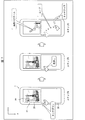
図3を用いて、タッチイベント判定部12による画像制御の一例を説明する。図3は、タッチイベント判定部12および表示制御部13によって実行される画像制御の一例を説明する図である。最初、主制御部10は、ポインタモードであるとする。
(Example of image control; Part 1)
An example of image control by the touch
図3に示すように、タッチパッド30において、タッチダウンが検知(ステップA)された場合、タッチ判定部121は、該タッチダウンに伴って発生した検知信号をタッチパッド制御部11から取得する。そして、タッチ判定部121は、取得した検知信号に基づいて、タッチパッド30上においてタッチダウンが検知された位置を判定する。
As illustrated in FIG. 3, when a touchdown is detected in the touchpad 30 (step A), the
主制御部10がポインタモードである場合、長押し判定部123は、タッチ操作が長押し操作であるか否か、より具体的には、タッチの継続時間が記憶部40の長押し閾値時間よりも長いか否か、を判定する。ここで、タッチの継続時間とは、タッチダウンが検知されてから、タッチアップまたはムーブが検知されるまでの時間のことである。
When the
タッチの継続時間が長押し閾値時間よりも長い場合(ステップB)、主制御部10は、ポインタモードからスクロールモードに遷移する。これに伴って、表示制御部13は、ディスプレイ20上のカーソルcrを消去する。また、タッチ判定部121は、タッチダウンが検知された位置を表示制御部13に通知し、表示制御部13は、タッチダウンが検知された位置に対応するディスプレイ20上の位置(以下では、対応位置と呼ぶ)にポインタptを表示(ステップB)する。ここで、タッチパッド30上の位置と、ディスプレイ20上の位置とは、予め一対一で対応付けられている。
When the duration of the touch is longer than the long press threshold time (step B), the
ディスプレイ20にポインタptが表示された後(すなわち、主制御部10がスクロールモードに遷移した後)、ムーブ判定部122は、タッチパッド30に対するムーブの操作(ステップC)を検知する。
After the pointer pt is displayed on the display 20 (that is, after the
ムーブ判定部122は、単位時間ごとに、タッチの位置(図3に×印で示す位置)の情報を、タッチパッド制御部11から取得する。そして、ムーブ判定部122は、タッチダウンが検知された時点から、単位時間が経過するまでの期間におけるタッチの位置の変化を、1回目のムーブの操作として検知する。また、ムーブ判定部122は、1回目のムーブの操作が開始された時点におけるタッチの位置(以下では、ムーブ始点と呼ぶ)から、1回目のムーブの操作が終了した時点におけるタッチの位置(以下では、ムーブ終点と呼ぶ)へ向かうムーブベクトルを計算する。
The
1回目のムーブの操作が検知された後、ムーブ判定部122は、1回目のムーブの操作が終了した時点から、単位時間が経過するまでの期間におけるタッチの位置の変化を、2回目のムーブの操作として検知する。また、ムーブ判定部122は、2回目のムーブのムーブ始点から、2回目のムーブのムーブ終点へ向かうムーブベクトルを計算する。以後、ムーブ判定部122は、同様にして、3回目以降のムーブのムーブベクトルを計算する。なお、ユーザ操作としての1回のスワイプは、タッチダウンが検知された時点から、タッチアップが検知される時点までの期間に含まれる全てのムーブの操作に相当する。
After the first move operation is detected, the
ムーブ判定部122は、上記ムーブベクトルの情報(または、ムーブ始点およびムーブ終点の情報)を、表示制御部13に通知する。表示制御部13は、上記ムーブベクトルに対応するディスプレイ20上のベクトルに沿って、画像表示領域pc内の画像をスクロール(ステップC)させる。ここで、ムーブベクトルに対応するディスプレイ20上のベクトルは、タッチパッド30内の座標系で検知された上記ムーブベクトルが、ディスプレイ20内の座標系に変換されることによって得られる。なお、表示制御部13は、ディスプレイ20上のポインタptを移動させることはない。
The
(画像制御の例;その2)
図4を用いて、タッチイベント判定部12による画像制御の他の例を説明する。図4は、タッチイベント判定部12および表示制御部13によって実行される画像制御の他の例を説明する図である。最初、主制御部10は、ポインタモードであるとする。
(Example of image control; 2)
Another example of image control by the touch
図4に示すように、まず、タッチダウン1が検知(ステップA)され、長押しの操作(ステップB)によって、主制御部10がスクロールモードに遷移する。タッチ判定部121は、タッチダウン1が検知された位置に対応するディスプレイ20上の対応位置に、ポインタptを表示(ステップB)させる。ここまでの画像制御の流れは、図3を用いて説明した画像制御の流れと同じである。
As shown in FIG. 4, first, the
その後、タッチアップ1およびタッチダウン2が続けて検知(ステップB−2)された場合、ムーブ判定部122は、タッチダウン2が検知された位置から、ムーブ終点へ向かうムーブベクトルを計算する。そして、ムーブ判定部122は、このように計算したムーブベクトルに沿って画像表示領域pc内の画像をスクロールするように、表示制御部13に指示する。表示制御部13は、ムーブ判定部122の指示に従って、ディスプレイ20上で画像表示領域pc内の画像をスクロール(ステップC)させる。
Thereafter, when the touch-
このように、タッチダウン1−タッチアップ1−タッチダウン2が検知された後でムーブが検知された場合、ムーブ判定部122によって計算されるムーブベクトルは、ムーブが検知される直前に検知されたタッチダウン(ここでは、タッチダウン2)の位置から、ムーブ終点へ向かうベクトルとなる。
As described above, when a move is detected after touchdown 1 -touchup 1 -
(画像制御内容決定処理の流れ)
図5および図6を用いて、タッチイベント判定部12によって実行される画像制御内容決定処理の流れを説明する。図5は、画像制御内容決定処理の流れを示すフローチャートである。図6は、タッチパッド30上におけるタッチの位置およびその変化を示すグラフである。最初、主制御部10は、ディスプレイ20上にカーソルcr(図3および図4参照)が表示されるポインタモードであるとする。
(Image control content determination process flow)
The flow of image control content determination processing executed by the touch
図5に示すように、画像制御内容決定処理では、まず、タッチ判定部121は、タッチパッド30上においてタッチダウン1が検知(図4のステップA参照)された場合、タッチダウン1が検知された位置(DX1、DY1)(図6参照)を判定する(S1、位置情報取得ステップ)。
As shown in FIG. 5, in the image control content determination process, first, the
次に、長押し判定部123は、長押し操作を検知(図3および図4のステップB参照)する(S2)。換言すれば、長押し判定部123は、タッチダウン1が長押し操作であると判定する。その後、タッチ判定部121は、タッチダウン1が検知された位置(DX1、DY1)を示す情報を記憶部40に記録する(S3)。
Next, the long press determination unit 123 detects a long press operation (see step B in FIGS. 3 and 4) (S2). In other words, the long press determination unit 123 determines that the
続いて、タッチ判定部121は、タッチパッド30上においてタッチダウン1が検知された位置を、表示制御部13に通知する。表示制御部13は、タッチダウン1が検知された位置に対応するディスプレイ20上の対応位置に、ポインタptを表示(図3および図4のステップB参照)する(S4)。
Subsequently, the
その後、タッチ判定部121は、タッチアップが検知されたか否かを判定する(S5)。タッチアップ1が検知されていない場合(S5でNo)、画像制御内容決定処理はS8に進む。一方、タッチアップが検知(図4のステップB−2参照)された場合(S5でYes)、タッチパッド30上において新たなタッチダウン2が検知(図4のステップB−2参照)されたとき、タッチ判定部121は、タッチダウン2の位置(DX2、DY2)(図6参照)を判定する(S6、位置情報取得ステップ)。そして、タッチ判定部121は、タッチダウン1が検知された位置(DX1、DY1)とタッチダウン2が検知された位置(DX2、DY2)との差分(ΔX=DX2−DX1、ΔY=DY2−DY1)(図6参照)を算出する(S7)。
Thereafter, the
次に、ムーブ判定部122は、タッチダウン2が検知された位置(DX2、DY2)から、単位時間後のタッチの位置(MX1、MY1)(図6参照)へ向かうムーブ1を検知する(S8)(図3および図4のステップC参照)。以下では、位置(DX2、DY2)をムーブ1の始点と呼び、位置(MX1、MY1)をムーブ1の終点と呼ぶ。なお、位置(MX1、MY1)において、タッチアップが検知されている必要はない。
Next, the
その後、ムーブ判定部122は、ムーブ1の補正終点(MX1´=MX1−ΔX、MY1´=MY1−ΔY)(図6参照)を計算する(S9)。なお、タッチアップ1が検知されていない場合(S5でNo)、ムーブ1の補正終点(MX1´、MY1´)は、ムーブ1の終点(MX1、MY1)に等しくなる。
Thereafter, the
続いて、ムーブ判定部122は、タッチダウン1が検知された位置(DX1、DY1)を、ムーブ1の補正始点として、表示制御部13(アプリケーション)に通知する(S10、表示制御ステップ)。また、ムーブ判定部122は、ムーブ1の補正終点(MX1´、MY1´)も、表示制御部13(アプリケーション)に通知する(S11、表示制御ステップ)。表示制御部13は、ムーブ1の補正始点(DX1、DY1)から補正終点(MX1´、MY1´)へ向かうムーブベクトル(MX1´−DX1、MY1´−DY1)をディスプレイ20内の座標系におけるベクトルに変換し、変換されたベクトルに沿って、画像表示領域pc内の画像をスクロールさせる(表示制御ステップ)。
Subsequently, the
あるいは、S10およびS11の代わりに、ムーブ判定部122は、ムーブ1の始点(DX2、DY2)と、ムーブ1の終点(MX1、MY1)とを、表示制御部13に通知してもよい。図6に示すように、ムーブ1の補正始点(DX1、DY1)から、ムーブ1の補正終点(MX1´、MY1´)へ向かうムーブベクトル(MX1´−DX1、MY1´−DY1)は、ムーブ1の始点(DX2、DY2)から、ムーブ1の終点(MX1、MY1)へ向かうベクトル(MX1−DX2、MY1−DY2)に等しい。そのため、上記ベクトル(MX1−DX2、MY1−DY2)からディスプレイ20内の座標系へ変換されたベクトルは、上記ムーブベクトル(MX1´−DX1、MY1´−DY1)からディスプレイ20内の座標系へ変換されたベクトルに等しくなる。
Alternatively, instead of S10 and S11, the
以後のS12〜17では、新たなムーブn(nは2以上の整数)の検知と、そのムーブnの通知とが実行される。 In subsequent S12 to S17, detection of a new move n (n is an integer of 2 or more) and notification of the move n are executed.
S13において、タッチアップが検知されず(S13でNo)、n回目のムーブnが検知された場合、画像制御内容決定処理のS12〜S17において、ムーブ判定部122は、ムーブnの補正始点およびムーブnの補正終点(MXn´=MXn−ΔX、MYn´=MYn−ΔY)を表示制御部13(アプリケーション)に通知する。ここで、ムーブnの補正始点は、n−1回目のムーブn−1の補正終点(MXn−1´=MX(n−1)−ΔX、MYn−1´=MY(n−1)−ΔY)である。
When the touch-up is not detected in S13 (No in S13) and the n-th move n is detected, in S12 to S17 of the image control content determination process, the
表示制御部13は、n回目のムーブnの補正始点(MXn−1´、DYn−1´)から、n回目のムーブnの補正終点(MXn´、MYn´)へ向かうムーブベクトル(MXn´−MXn−1´、MYn´−MYn−1´)を、ディスプレイ20内の座標系におけるベクトルに変換し、変換したベクトルに沿って、画像表示領域pc内の画像をスクロールさせる(表示制御ステップ)。
The
なお、ムーブnの補正始点およびムーブnの補正終点の情報は、表示制御部13だけでなく、携帯端末装置1に実装されたアプリケーションにも通知され、該アプリケーションは、通知されたムーブnの操作に応じて、画像表示領域pc内の画像に対するアクションを実行してもよい。
The information of the correction start point of move n and the correction end point of move n is notified not only to the
図6では、1回目のムーブ1のムーブベクトルおよび2回目のムーブ2のムーブベクトルは、どちらも、タッチパッド30内の座標系(直交座標系)において、斜め方向(xy座標軸と交わる方向)のムーブベクトルである。しかしながら、本発明では、n(≧2)回のムーブ1〜nが検知された場合、1回目のムーブ1からn回目のムーブnのうち、少なくとも1回のムーブm(1≦m≦n)のムーブベクトルが、タッチパッド30上の座標系において、斜め方向のベクトルであればよい。
In FIG. 6, the move vector of the
n回目のムーブnが検知された後、タッチアップが検知された場合(S13でYes)、画像制御内容決定処理は終了する。 If the touch-up is detected after the n-th move n is detected (Yes in S13), the image control content determination process ends.
(変形例)
図4には、2回のタッチダウン1、2が検知された場合における画像制御の流れを示している。また、画像制御内容決定処理の流れの説明でも、2回のタッチダウン1、2が行われた場合を想定した。本変形例では、図6を用いて、3回目のタッチダウンが検知された場合の画像制御の流れを説明する。
(Modification)
FIG. 4 shows the flow of image control when two
図6に示すように、2回目のムーブ2の後に、(2回目のタッチアップが検出された後)3回目のタッチダウンが検知された場合、タッチ判定部121は、3回目のタッチダウンが検知された位置(DX3、DY3)と2回目のムーブ2の終点(MX2、MY2)との差分(ΔM=DX3−MX2、ΔN=DY3−MY2)を算出する。
As shown in FIG. 6, when the third touchdown is detected after the second move 2 (after the second touchup is detected), the
次に、ムーブ判定部122は、3回目のタッチダウンが検知された位置(DX3、DY3)から、単位時間後のタッチの位置(MX3、MY3)へ向かうムーブを検知する。その後、ムーブ判定部122は、上記ムーブの補正始点(DX3−ΔX−ΔN、DY3−ΔY−ΔN)、および、上記ムーブの補正終点(MX3´=MX3−ΔX−ΔM、MY3´=MY3−ΔY−ΔN)を計算する。
Next, the
そして、ムーブ判定部122は、上記ムーブの補正始点(DX3−ΔX−ΔN、DY3−ΔY−ΔN)および補正終点(MX3´、MY3´)を表示制御部13に通知する。
Then, the
表示制御部13は、上記ムーブの補正始点(DX3−ΔX−ΔN、DY3−ΔY−ΔN)から補正終点(MX3´、MY3´)へ向かうムーブベクトルを、ディスプレイ20内の座標系におけるベクトルに変換し、変換されたベクトルに沿って、画像表示領域pc内の画像をスクロールさせる。
The
〔実施形態2〕
本発明の他の実施形態について、図7に基づいて説明すれば、以下のとおりである。なお、説明の便宜上、前記実施形態にて説明した部材と同じ機能を有する部材については、同じ符号を付記し、その説明を省略する。
[Embodiment 2]
The following will describe another embodiment of the present invention with reference to FIG. For convenience of explanation, members having the same functions as those described in the embodiment are given the same reference numerals, and descriptions thereof are omitted.
前記実施形態1では、タッチパッド30に対して長押し操作が行われた場合、主制御部10がポインタモードからスクロールモードに遷移するとともに、ディスプレイ20上にポインタptが表示(図3のステップB参照)される構成を説明した。しかしながら、主制御部10がスクロールモードに遷移した場合であっても、ディスプレイ20にポインタptが表示されることは必須ではない。
In the first embodiment, when a long press operation is performed on the
本実施形態では、主制御部10がスクロールモードである場合であっても、ディスプレイ20にポインタptが表示されない構成を説明する。
In the present embodiment, a configuration in which the pointer pt is not displayed on the
(画像制御の例;その3)
図7は、本実施形態に係るタッチイベント判定部12および表示制御部13によって実行される画像制御の例を示す説明図である。
(Example of image control; Part 3)
FIG. 7 is an explanatory diagram illustrating an example of image control executed by the touch
図7に示すように、本実施形態では、携帯端末装置1の主制御部10がポインタモードである場合において、タッチダウン1が検知(ステップA)され、さらに長押しが検知(ステップB)された場合、主制御部10は、ポインタモードからスクロールモードに遷移する。このとき、本実施形態に係るタッチ判定部121は、ディスプレイ20上のカーソルcrを消去するが、ディスプレイ20上にポインタを表示しない。なお、本実施形態では、前記実施形態1のようには、長押しが検知された位置に対応するディスプレイ20上の対応位置にポインタが表示されないので、主制御部10は、長押し以外の操作によって、ポインタモードからスクロールモードに遷移しても構わない。
As shown in FIG. 7, in the present embodiment, when the
主制御部10がスクロールモードに遷移した後、ムーブが検知された場合、タッチイベント判定部12および表示制御部13は、前記実施形態1で説明した画像制御内容決定処理の手順に従って、画像表示領域pc内の画像をスクロール(ステップC)させる。
When the movement is detected after the
以上のように、本実施形態では、主制御部10がスクロールモードに遷移した場合であっても、ディスプレイ20にポインタが表示されない。そのため、ポインタと画像とが重なって表示されることがないので、ユーザが画像を見やすいという利点を有する。
As described above, in the present embodiment, no pointer is displayed on the
〔実施形態3〕
本発明の他の実施形態について、図8に基づいて説明すれば、以下のとおりである。なお、説明の便宜上、前記実施形態にて説明した部材と同じ機能を有する部材については、同じ符号を付記し、その説明を省略する。
[Embodiment 3]
The following will describe another embodiment of the present invention with reference to FIG. For convenience of explanation, members having the same functions as those described in the embodiment are given the same reference numerals, and descriptions thereof are omitted.
前記実施形態1および2では、ディスプレイ20上に1つの画像表示領域pcが含まれており、その画像表示領域pc内の画像がスクロールされる構成を説明した。本実施形態では、ディスプレイ20上に複数の画像が表示されており、それらの画像のいずれかがスクロールされる構成を説明する。
In the first and second embodiments, the configuration in which one image display area pc is included on the
(画像制御の例;その4)
図8は、本実施形態に係るタッチイベント判定部12および表示制御部13によって実行される画像制御の例を示す説明図である。図8に示すように、ディスプレイ20上には、2つの画像表示領域区画pc1、pc2(区画)が表示されている。しかしながら、ディスプレイ20上には、3つ以上の画像が表示されていてもよい。
(Example of image control; Part 4)
FIG. 8 is an explanatory diagram illustrating an example of image control executed by the touch
図8に示すように、本実施形態では、主制御部10がポインタモードである場合において、タッチダウン1が検知(ステップA)され、さらに長押しが検知(ステップB)された場合、主制御部10は、ポインタモードからスクロールモードに遷移する。本実施形態に係るタッチ判定部121は、ディスプレイ20上のカーソルcrを消去するとともに、ディスプレイ20上にポインタを表示(ステップB)する。このとき、ポインタptは、タッチダウン1が検知された位置に対応するディスプレイ20上の対応位置に表示される。図8では、ポインタptは画像表示領域区画pc2内に表示されている。
As shown in FIG. 8, in the present embodiment, when the
その後、ムーブが検知された場合、タッチイベント判定部12および表示制御部13は、前記実施形態1で説明した画像制御内容決定処理の手順に従って、画像表示領域区画pc2内の画像をスクロール(ステップC)させる。一方、タッチイベント判定部12および表示制御部13は、ポインタptが表示されていない画像表示領域区画pc1内の画像をスクロールさせない。
Thereafter, when a move is detected, the touch
以上のように、本実施形態では、ディスプレイ20に表示されている複数の区画のうち、ポインタptが表示されている区画内の表示のみがスクロールされる。そのため、ユーザは、タッチパッド30上における適切な位置を長押しして、所望の区画上にポインタptを表示させることによって、その区画内の画像のみをスクロールさせることができる。
As described above, in the present embodiment, only the display in the section where the pointer pt is displayed among the plurality of sections displayed on the
なお、ムーブおよびタッチアップが検知(図8のステップC)された後、タッチダウンおよびムーブの操作がさらに検知された場合(図4のステップB−2およびステップC参照)、ポインタptが表示されている画像表示領域区画pc2内の表示がさらにスクロールされる。 If a touchdown and move operation is further detected (see step B-2 and step C in FIG. 4) after a move and touchup is detected (step C in FIG. 8), a pointer pt is displayed. The display in the displayed image display area section pc2 is further scrolled.
〔ソフトウェアによる実現例〕
携帯端末装置1の制御ブロック(特に主制御部10)は、集積回路(ICチップ)等に形成された論理回路(ハードウェア)によって実現してもよいし、CPU(Central Processing Unit)を用いてソフトウェアによって実現してもよい。
[Example of software implementation]
The control block (particularly the main control unit 10) of the mobile
後者の場合、携帯端末装置1は、各機能を実現するソフトウェアであるプログラムの命令を実行するCPU、上記プログラムおよび各種データがコンピュータ(またはCPU)で読み取り可能に記録されたROM(Read Only Memory)または記憶装置(これらを「記録媒体」と称する)、上記プログラムを展開するRAM(Random Access Memory)などを備えている。そして、コンピュータ(またはCPU)が上記プログラムを上記記録媒体から読み取って実行することにより、本発明の目的が達成される。上記記録媒体としては、「一時的でない有形の媒体」、例えば、テープ、ディスク、カード、半導体メモリ、プログラマブルな論理回路などを用いることができる。また、上記プログラムは、該プログラムを伝送可能な任意の伝送媒体(通信ネットワークや放送波等)を介して上記コンピュータに供給されてもよい。なお、本発明は、上記プログラムが電子的な伝送によって具現化された、搬送波に埋め込まれたデータ信号の形態でも実現され得る。
In the latter case, the mobile
〔まとめ〕
本発明の態様1に係る情報処理装置(主制御部10)は、表示部(ディスプレイ20)と、近接または接触する物体を検出する平面状の検出領域を上記表示部の表示領域とは異なる位置に有する物体検出部(タッチパッド30)と、上記物体検出部が上記物体を検出した位置を示す位置情報を取得する位置情報取得部(タッチイベント判定部12)とを備えた情報処理装置であって、上記表示部の表示領域の座標系と上記物体検出部の検出領域の座標系とが対応付けられており、上記位置情報取得部が、上記検出領域の座標系の座標軸と交わる方向への上記物体の斜め移動を検出した場合、上記検出領域の座標系における上記物体の斜め移動の方向および量に対応する上記表示領域の座標系における方向および量によって、上記表示部の表示を上記表示領域の座標系において斜め移動させる表示制御部(13)をさらに備えている。
[Summary]
In the information processing apparatus (main control unit 10) according to the first aspect of the present invention, the display unit (display 20) and a planar detection region for detecting an object that is close to or in contact with the display unit are positioned at positions different from the display region of the display unit The information processing apparatus includes an object detection unit (touch pad 30) and a position information acquisition unit (touch event determination unit 12) that acquires position information indicating a position where the object detection unit detects the object. The coordinate system of the display area of the display unit and the coordinate system of the detection area of the object detection unit are associated with each other, and the position information acquisition unit in a direction intersecting the coordinate axis of the coordinate system of the detection area When the oblique movement of the object is detected, the display of the display unit is determined according to the direction and amount of the display area in the coordinate system corresponding to the direction and amount of the oblique movement of the object in the coordinate system of the detection area. Further comprising a display control unit for obliquely moving (13) in the coordinate system of the display area.
上記の構成によれば、物体(例えば、ユーザの指)が物体検出部の検出領域内で斜め方向に移動したことが検出された場合、物体検出部で検出された移動の方向および距離に対応する方向および距離で、表示部の表示領域内の表示が斜め移動する。そのため、ユーザは、物体検出部の検出領域内で指やスライタスペンを斜めの方向に移動させることによって、表示領域内の表示をその斜めの方向(に対応する方向)へ移動(スクロール)させることができる。 According to the above configuration, when an object (for example, a user's finger) is detected to move in an oblique direction within the detection area of the object detection unit, it corresponds to the direction and distance of the movement detected by the object detection unit. The display in the display area of the display unit moves diagonally according to the direction and the distance. Therefore, the user can move (scroll) the display in the display area in the oblique direction (corresponding direction) by moving the finger or the slitus pen in the oblique direction in the detection area of the object detection unit. it can.
本発明の態様2に係る情報処理装置は、上記態様1において、上記表示制御部は、上記位置情報取得部が、上記斜め移動を含む、上記検出領域における上記物体の移動を連続して複数回検出したとき、先に検出した上記物体の移動から順に、上記検出領域の座標系における上記物体の移動の方向および量に対応する上記表示領域の座標系における方向および量によって、上記表示部の表示を上記表示領域の座標系において移動させる処理を、上記複数回連続して行ってもよい。
The information processing apparatus according to
上記の構成によれば、検出領域における物体の移動が連続して複数回検出された場合、各移動の方向および量に対応する表示領域の座標系における方向および量によって、表示部の表示領域内の表示を移動させることができる。 According to the above configuration, when the movement of the object in the detection region is detected a plurality of times in succession, the direction and amount in the coordinate system of the display region corresponding to the direction and amount of each movement The display of can be moved.
本発明の態様3に係る情報処理装置は、上記態様1または2において、上記表示領域は1または複数の区画よりなり、上記表示制御部は、上記位置情報取得部が検出した上記検出領域の座標系における上記物体の移動の方向および量に対応する上記表示領域の座標系における方向および量によって、上記表示部の表示を上記表示領域の座標系において移動させる処理を行うとき、表示を移動させる対象となる上記区画に所定の標識を表示してもよい。
In the information processing apparatus according to
上記の構成によれば、複数の区画内の表示のうち、移動される表示が、所定の標識によって示される。そのため、ユーザは、標識を確認することによって、どの区画内の表示を移動(スクロール)させることができるのかを知ることができる。 According to said structure, the display which is moved among the displays in a some division is shown by a predetermined | prescribed label | marker. Therefore, the user can know in which section the display can be moved (scrolled) by checking the sign.
本発明の態様4に係る制御方法は、表示部(ディスプレイ20)と、近接または接触する物体を検出する平面状の検出領域を上記表示部の表示領域とは異なる位置に有する物体検出部(タッチパッド30)とを備えた情報処理装置の制御方法であって、上記表示部の表示領域の座標系と上記物体検出部の検出領域の座標系とが対応付けられており、上記物体検出部が上記物体を検出した位置を示す位置情報を取得する位置情報取得ステップ(S1、S6)と、上記位置情報取得ステップにおいて、上記検出領域の座標系の座標軸と交わる方向への上記物体の斜め移動が検出された場合、上記検出領域の座標系における上記物体の斜め移動の方向および量に対応する上記表示領域の座標系における方向および量によって、上記表示部の表示を上記表示領域の座標系において斜め移動させる表示制御ステップ(S10、S11)とを含んでいる。
The control method according to
上記の構成によれば、上記態様1に係る情報処理装置と同じ効果を奏することができる。
According to said structure, there can exist the same effect as the information processing apparatus which concerns on the said
本発明の各態様に係る情報処理装置は、コンピュータによって実現してもよく、この場合には、コンピュータを上記情報処理装置が備える各部(ソフトウェア要素)として動作させることにより上記情報処理装置をコンピュータにて実現させる情報処理装置の制御プログラム、およびそれを記録したコンピュータ読み取り可能な記録媒体も、本発明の範疇に入る。 The information processing apparatus according to each aspect of the present invention may be realized by a computer. In this case, the information processing apparatus is operated on each computer by causing the computer to operate as each unit (software element) included in the information processing apparatus. The control program for the information processing apparatus to be realized in this way and a computer-readable recording medium on which the control program is recorded also fall within the scope of the present invention.
本発明は上述した各実施形態に限定されるものではなく、請求項に示した範囲で種々の変更が可能であり、異なる実施形態にそれぞれ開示された技術的手段を適宜組み合わせて得られる実施形態についても本発明の技術的範囲に含まれる。さらに、各実施形態にそれぞれ開示された技術的手段を組み合わせることにより、新しい技術的特徴を形成することができる。 The present invention is not limited to the above-described embodiments, and various modifications are possible within the scope shown in the claims, and embodiments obtained by appropriately combining technical means disclosed in different embodiments. Is also included in the technical scope of the present invention. Furthermore, a new technical feature can be formed by combining the technical means disclosed in each embodiment.
本発明は、タッチパッドおよび画面を備えた情報処理装置に利用することができる。 The present invention can be used for an information processing apparatus including a touch pad and a screen.
10 主制御部(情報処理装置)
20 ディスプレイ(表示部)
30 タッチパッド(物体検出部)
12 タッチイベント判定部(位置情報取得部)
13 表示制御部
pt ポインタ(標識)
pc 画像表示領域(表示領域)
pc1、pc2 画像表示領域区画(表示領域、区画)
10 Main control unit (information processing device)
20 Display (display part)
30 Touchpad (object detection unit)
12 Touch event determination unit (location information acquisition unit)
13 Display control part pt Pointer (sign)
pc Image display area (display area)
pc1, pc2 Image display area section (display area, section)
Claims (11)
上記表示部の表示領域とは異なる位置に配置された操作面と、
上記操作面に配置された物理的なキーと、
上記操作面に近接または接触する物体を検出する物体検出部と、
制御部とを備えた情報処理装置であって、
上記制御部は、
上記物体検出部に対する操作による、上記表示部が表示するカーソルの移動、および、上記カーソルがある位置での決定の入力を可能にするポインタモードと、上記キーに対する操作による数字または文字の入力を可能にするキー操作モードとを有し、
上記ポインタモードにおいて、上記キーが押下されたときに、上記キー操作モードに遷移せずに、上記カーソルを非表示状態にさせることを特徴とする情報処理装置。 A display unit;
An operation surface arranged at a position different from the display area of the display unit;
A physical key arranged on the operation surface;
An object detection unit for detecting an object close to or in contact with the operation surface;
An information processing apparatus comprising a control unit,
The control unit
Pointer mode that allows the cursor displayed on the display unit to be moved by the operation on the object detection unit and the determination input at the position where the cursor is located, and the input of numbers or characters by the operation on the key is possible. And a key operation mode to
In the pointer mode, when the key is pressed, the information processing apparatus makes the cursor non-display state without transitioning to the key operation mode .
上記物体検出部に対する操作による、上記表示部の表示領域内の表示のスクロールを可能にするスクロールモードをさらに有し、
上記ポインタモードにおいて、上記物体検出部に対してロングタップがなされたとき、上記スクロールモードに遷移することを特徴とする請求項1または2に記載の情報処理装置。 The control unit
A scroll mode that enables scrolling of the display in the display area of the display unit by an operation on the object detection unit;
3. The information processing apparatus according to claim 1, wherein in the pointer mode, when a long tap is performed on the object detection unit, transition to the scroll mode is performed. 4.
上記ポインタモードから上記スクロールモードに遷移するとき、上記表示部に、上記物体検出部に対するタッチダウンの位置に対応する位置に上記標識を表示させ、
上記スクロールモードでは、上記物体検出部に対する操作がなされても、上記標識の位置を変化させないことを特徴とする請求項6に記載の情報処理装置。 The control unit
When transitioning from the pointer mode to the scroll mode, the display unit displays the sign at a position corresponding to the touchdown position with respect to the object detection unit,
The information processing apparatus according to claim 6, wherein, in the scroll mode, the position of the sign is not changed even when an operation is performed on the object detection unit.
上記制御部は、上記スクロールモードにおいて、上記物体検出部が検出した上記物体が、上記検出領域の座標系の座標軸と交わる方向へ斜め移動したとき、上記検出領域の座標系における上記物体の斜め移動の方向および量に対応する上記表示領域の座標系における方向および量によって、上記表示部の表示領域内の表示を上記表示領域の座標系において斜め移動させることを特徴とする請求項3〜7の何れか一項に記載の情報処理装置。 The coordinate system of the display area of the display unit is associated with the coordinate system of the detection area of the object detection unit,
In the scroll mode, when the object detected by the object detection unit is moved obliquely in a direction intersecting with the coordinate axis of the coordinate system of the detection area, the control unit is moved obliquely in the coordinate system of the detection area. The display in the display area of the display unit is moved obliquely in the coordinate system of the display area according to the direction and quantity in the coordinate system of the display area corresponding to the direction and quantity of the display area. The information processing apparatus according to any one of claims.
上記キー操作モードにおいて、上記物体検出部に対する操作を無効化し、
上記キー操作モードにおいて、特定のアプリケーションを起動したときに、上記ポインタモードに遷移することを特徴とする請求項1〜8の何れか一項に記載の情報処理装置。 The control unit
In the key operation mode, the operation for the object detection unit is invalidated ,
The information processing apparatus according to any one of claims 1 to 8, wherein when the specific application is activated in the key operation mode, the mode is changed to the pointer mode.
上記キー操作モードにおいて、上記物体検出部に対する操作を無効化し、
上記キー操作モード以外のモードにおいて、特定のアプリケーションを終了したときに、上記キー操作モードに遷移することを特徴とする請求項1〜8の何れか一項に記載の情報処理装置。 The control unit
In the key operation mode, the operation for the object detection unit is invalidated ,
The information processing apparatus according to any one of claims 1 to 8, wherein when a specific application is terminated in a mode other than the key operation mode, the mode is changed to the key operation mode.
Priority Applications (1)
| Application Number | Priority Date | Filing Date | Title |
|---|---|---|---|
| JP2015006035A JP6077573B2 (en) | 2015-01-15 | 2015-01-15 | Information processing apparatus, control method thereof, and control program |
Applications Claiming Priority (1)
| Application Number | Priority Date | Filing Date | Title |
|---|---|---|---|
| JP2015006035A JP6077573B2 (en) | 2015-01-15 | 2015-01-15 | Information processing apparatus, control method thereof, and control program |
Related Child Applications (2)
| Application Number | Title | Priority Date | Filing Date |
|---|---|---|---|
| JP2016177931A Division JP6027703B1 (en) | 2016-09-12 | 2016-09-12 | Information processing apparatus and control program |
| JP2017003563A Division JP6118005B1 (en) | 2017-01-12 | 2017-01-12 | Information processing apparatus and control program |
Publications (3)
| Publication Number | Publication Date |
|---|---|
| JP2016133827A JP2016133827A (en) | 2016-07-25 |
| JP2016133827A5 JP2016133827A5 (en) | 2016-09-15 |
| JP6077573B2 true JP6077573B2 (en) | 2017-02-08 |
Family
ID=56437977
Family Applications (1)
| Application Number | Title | Priority Date | Filing Date |
|---|---|---|---|
| JP2015006035A Expired - Fee Related JP6077573B2 (en) | 2015-01-15 | 2015-01-15 | Information processing apparatus, control method thereof, and control program |
Country Status (1)
| Country | Link |
|---|---|
| JP (1) | JP6077573B2 (en) |
Families Citing this family (1)
| Publication number | Priority date | Publication date | Assignee | Title |
|---|---|---|---|---|
| KR102601905B1 (en) * | 2016-09-21 | 2023-11-15 | 삼성전자주식회사 | Operating method for touch pad and electronic device supporting the same |
Family Cites Families (3)
| Publication number | Priority date | Publication date | Assignee | Title |
|---|---|---|---|---|
| JPH0476724A (en) * | 1990-07-19 | 1992-03-11 | Canon Inc | Information processor |
| TWI330331B (en) * | 2005-07-04 | 2010-09-11 | Atlab Inc | Input device for content providing device and method of operating the same |
| JP4650559B2 (en) * | 2008-11-25 | 2011-03-16 | ソニー株式会社 | Information processing apparatus, information processing method, information processing system, and information processing program |
-
2015
- 2015-01-15 JP JP2015006035A patent/JP6077573B2/en not_active Expired - Fee Related
Also Published As
| Publication number | Publication date |
|---|---|
| JP2016133827A (en) | 2016-07-25 |
Similar Documents
| Publication | Publication Date | Title |
|---|---|---|
| WO2016114269A1 (en) | Information processing device and control method therefor | |
| CN104145236B (en) | Method and apparatus for the content in mobile terminal | |
| US8839154B2 (en) | Enhanced zooming functionality | |
| JP6381032B2 (en) | Electronic device, control method thereof, and program | |
| US10182141B2 (en) | Apparatus and method for providing transitions between screens | |
| JP6107663B2 (en) | Information processing device | |
| JPWO2014141548A1 (en) | Display control | |
| JP2014197164A (en) | Display device, display method and display program | |
| JP6027703B1 (en) | Information processing apparatus and control program | |
| JPWO2012144616A1 (en) | Electronic device, control method of electronic device, and program | |
| JP6077573B2 (en) | Information processing apparatus, control method thereof, and control program | |
| US20170010791A1 (en) | Information processing apparatus, non-transitory computer readable storage medium, and information display method | |
| JP6118005B1 (en) | Information processing apparatus and control program | |
| JP6134748B2 (en) | Information processing apparatus, control method thereof, and control program | |
| KR20090017828A (en) | Method for controling interface, and apparatus for implementing the same | |
| JP2016224688A (en) | Information processing device, control method, control program, and recording medium | |
| JP6367720B2 (en) | Information processing apparatus and program | |
| JP6114886B2 (en) | Information processing apparatus, control method for information processing apparatus, and control program | |
| JP2016130976A (en) | Information processing apparatus, control method thereof, and control program | |
| US20180329610A1 (en) | Object Selection Mode | |
| CN110945469A (en) | Touch input device and method | |
| CN104657061B (en) | The methods of screenshotss and apply its electronic installation | |
| JP6603797B2 (en) | Information processing apparatus, information processing apparatus control method, and control program | |
| JP2019079152A (en) | Information control program, information control method and terminal device | |
| JP2016218859A (en) | Information processing device, control method, and control program |
Legal Events
| Date | Code | Title | Description |
|---|---|---|---|
| A521 | Request for written amendment filed |
Free format text: JAPANESE INTERMEDIATE CODE: A523 Effective date: 20160729 |
|
| A621 | Written request for application examination |
Free format text: JAPANESE INTERMEDIATE CODE: A621 Effective date: 20160729 |
|
| A871 | Explanation of circumstances concerning accelerated examination |
Free format text: JAPANESE INTERMEDIATE CODE: A871 Effective date: 20160729 |
|
| A975 | Report on accelerated examination |
Free format text: JAPANESE INTERMEDIATE CODE: A971005 Effective date: 20160906 |
|
| A131 | Notification of reasons for refusal |
Free format text: JAPANESE INTERMEDIATE CODE: A131 Effective date: 20160927 |
|
| A521 | Request for written amendment filed |
Free format text: JAPANESE INTERMEDIATE CODE: A523 Effective date: 20161121 |
|
| TRDD | Decision of grant or rejection written | ||
| A01 | Written decision to grant a patent or to grant a registration (utility model) |
Free format text: JAPANESE INTERMEDIATE CODE: A01 Effective date: 20161213 |
|
| A61 | First payment of annual fees (during grant procedure) |
Free format text: JAPANESE INTERMEDIATE CODE: A61 Effective date: 20170112 |
|
| R150 | Certificate of patent or registration of utility model |
Ref document number: 6077573 Country of ref document: JP Free format text: JAPANESE INTERMEDIATE CODE: R150 |
|
| LAPS | Cancellation because of no payment of annual fees |