JP6074955B2 - Information processing apparatus and control method - Google Patents
Information processing apparatus and control method Download PDFInfo
- Publication number
- JP6074955B2 JP6074955B2 JP2012191491A JP2012191491A JP6074955B2 JP 6074955 B2 JP6074955 B2 JP 6074955B2 JP 2012191491 A JP2012191491 A JP 2012191491A JP 2012191491 A JP2012191491 A JP 2012191491A JP 6074955 B2 JP6074955 B2 JP 6074955B2
- Authority
- JP
- Japan
- Prior art keywords
- circuit
- individual
- arithmetic
- thread
- circuits
- Prior art date
- Legal status (The legal status is an assumption and is not a legal conclusion. Google has not performed a legal analysis and makes no representation as to the accuracy of the status listed.)
- Expired - Fee Related
Links
- 238000000034 method Methods 0.000 title claims description 89
- 230000010365 information processing Effects 0.000 title claims description 42
- 230000005856 abnormality Effects 0.000 claims description 85
- 230000008569 process Effects 0.000 claims description 65
- 238000012545 processing Methods 0.000 claims description 60
- 230000015654 memory Effects 0.000 claims description 57
- 238000001514 detection method Methods 0.000 claims description 11
- 230000026676 system process Effects 0.000 claims description 5
- 238000005192 partition Methods 0.000 description 18
- 238000010586 diagram Methods 0.000 description 15
- 239000000872 buffer Substances 0.000 description 12
- 230000002159 abnormal effect Effects 0.000 description 9
- 238000000926 separation method Methods 0.000 description 5
- 230000007704 transition Effects 0.000 description 5
- 238000004891 communication Methods 0.000 description 4
- 230000006870 function Effects 0.000 description 4
- 238000010348 incorporation Methods 0.000 description 2
- 230000004044 response Effects 0.000 description 2
- 230000008859 change Effects 0.000 description 1
- 230000009977 dual effect Effects 0.000 description 1
- 238000005516 engineering process Methods 0.000 description 1
- 238000009434 installation Methods 0.000 description 1
- 238000012544 monitoring process Methods 0.000 description 1
- 239000007787 solid Substances 0.000 description 1
- 239000000758 substrate Substances 0.000 description 1
- 238000012546 transfer Methods 0.000 description 1
- 238000013519 translation Methods 0.000 description 1
Images


Classifications
-
- G—PHYSICS
- G06—COMPUTING; CALCULATING OR COUNTING
- G06F—ELECTRIC DIGITAL DATA PROCESSING
- G06F21/00—Security arrangements for protecting computers, components thereof, programs or data against unauthorised activity
- G06F21/10—Protecting distributed programs or content, e.g. vending or licensing of copyrighted material ; Digital rights management [DRM]
- G06F21/105—Arrangements for software license management or administration, e.g. for managing licenses at corporate level
-
- G—PHYSICS
- G06—COMPUTING; CALCULATING OR COUNTING
- G06F—ELECTRIC DIGITAL DATA PROCESSING
- G06F21/00—Security arrangements for protecting computers, components thereof, programs or data against unauthorised activity
- G06F21/70—Protecting specific internal or peripheral components, in which the protection of a component leads to protection of the entire computer
Description
本発明は、情報処理装置および制御方法に関する。 The present invention relates to an information processing apparatus and a control method.
CoD(Capacity on Demand)は、サーバコンピュータなどの情報処理装置において、CPU(Central Processing Unit)などのハードウェア資源をユーザが必要な分だけ使用できるようにするものである。 CoD (Capacity on Demand) allows a user to use hardware resources such as a CPU (Central Processing Unit) as much as necessary in an information processing apparatus such as a server computer.
例えば、CoDによりCPUの使用数を制限する方法としては、ユーザは、複数のCPUが搭載された情報処理装置を購入する際、使用するCPUの数に応じた料金を支払う。これにより情報処理装置は、料金に応じた数のCPUが動作する一方、その数を超えたCPUの動作が禁止された状態で、ユーザに提供される。その後、情報処理装置の処理能力の増強が必要になった場合には、ユーザは、CPUの使用権を新たに購入することで、それまで使用していなかったCPUを直ちに使用可能になる。 For example, as a method of limiting the number of CPUs used by CoD, when a user purchases an information processing apparatus equipped with a plurality of CPUs, the user pays a fee according to the number of CPUs to be used. As a result, the information processing apparatus is provided to the user in a state in which the number of CPUs corresponding to the fee operates and the operation of the CPU exceeding the number is prohibited. Thereafter, when the processing capability of the information processing apparatus needs to be increased, the user can immediately use a CPU that has not been used so far by purchasing a new right to use the CPU.
CoDに関する技術の一例として、使用権が設定されたプロセッサが故障した場合に、使用権が設定されていない置き換えプロセッサを始動させて、故障プロセッサを停止させるようにしたものがある。 As an example of the technology related to CoD, when a processor to which usage rights are set fails, a replacement processor to which usage rights are not set is started to stop the failed processor.
また、近年のマルチコアプロセッサの中には、プロセッサ内の各コアの内部に複数のハードウェアスレッドを備えるものがある。ハードウェアスレッドは「ストランド(Strand)」と呼ばれることもある。コア内のハードウェアスレッドは、それぞれ個別の処理を並列に実行可能である。また、ハードウェアスレッドごとにレジスタなどのハードウェア資源が個別に設けられることもある。 Some recent multi-core processors include a plurality of hardware threads inside each core in the processor. A hardware thread is sometimes referred to as a “Strand”. Each hardware thread in the core can execute individual processes in parallel. In addition, hardware resources such as registers may be provided for each hardware thread.
ところで、上記のように複数のハードウェアスレッドを備えたコアを複数含むマルチコアプロセッサが搭載された情報処理装置において、CoDによりコアごとに使用権を設定した場合には、次のような問題がある。ハードウェアスレッドごとに個別に設けられたハードウェアのいずれかに異常が発生したときに、異常が発生したハードウェアスレッドを別のハードウェアスレッドに置き換えると、その置き換えの仕方によってはライセンス超過が発生する場合がある。 By the way, in the information processing apparatus equipped with a multi-core processor including a plurality of cores having a plurality of hardware threads as described above, when the usage right is set for each core by CoD, there are the following problems. . When an error occurs in one of the hardware provided separately for each hardware thread, if the hardware thread in which the error occurred is replaced with another hardware thread, the license may be exceeded depending on the replacement method. There is a case.
1つの側面では、本発明は、異常が発生したハードウェアの置き換え時におけるライセンス超過の発生を防止した情報処理装置および制御方法を提供することを目的とする。 In one aspect, an object of the present invention is to provide an information processing apparatus and a control method that prevent occurrence of license excess when replacing hardware in which an abnormality has occurred.
1つの案では、複数の処理を並列に実行可能であって、並列に実行する処理ごとに個別に設けられた個別回路を有する演算回路を、複数備えた情報処理装置が提供される。この情報処理装置は、次のような記憶部および制御部を有する。記憶部は、演算回路を単位として設定された使用権の数を記憶する。制御部は、複数の演算回路のうち、使用権の数の演算回路の動作を許可する。また、制御部は、動作中の演算回路に搭載されたいずれかの個別回路の異常を検知すると、異常が検知された個別回路が搭載された演算回路における他の個別回路の動作を停止させ、動作していないいずれかの演算回路の動作を開始させる。 In one proposal, an information processing apparatus is provided that can execute a plurality of processes in parallel and includes a plurality of arithmetic circuits each having an individual circuit provided for each process to be executed in parallel. This information processing apparatus includes the following storage unit and control unit. The storage unit stores the number of usage rights set in units of arithmetic circuits. A control part permits operation | movement of the arithmetic circuit of the number of usage rights among several arithmetic circuits. In addition, when the control unit detects an abnormality in any of the individual circuits mounted on the arithmetic circuit in operation, the control unit stops the operation of the other individual circuits in the arithmetic circuit in which the individual circuit in which the abnormality is detected is installed, The operation of any arithmetic circuit that is not operating is started.
また、1つの案では、上記の情報処理装置と同様の処理を実行する制御方法が提供される。 Further, in one proposal, a control method for executing the same processing as that of the information processing apparatus is provided.
1態様によれば、情報処理装置および制御方法において、異常が発生したハードウェアの置き換え時におけるライセンス超過の発生を防止できる。 According to the first aspect, in the information processing apparatus and the control method, it is possible to prevent the occurrence of excess licenses when replacing hardware in which an abnormality has occurred.
以下、本発明の実施の形態について図面を参照して説明する。
〔第1の実施の形態〕
図1は、第1の実施の形態に係る情報処理装置の構成例およびその動作例を示す図である。図1に示す情報処理装置1は、記憶部2、制御部3および複数の演算回路を有している。図1の例では、情報処理装置1は2つの演算回路11,12を備えているが、演算回路の搭載数は2つ以上の任意の数とすることができる。
Hereinafter, embodiments of the present invention will be described with reference to the drawings.
[First Embodiment]
FIG. 1 is a diagram illustrating a configuration example and an operation example of the information processing apparatus according to the first embodiment. An
演算回路11,12は、例えば、プロセッサの内部に搭載されるプロセッサコア、またはプロセッサとして実現される。制御部3も、例えば、プロセッサコアまたはプロセッサとして実現される。制御部3は、例えば、複数の演算回路のうちの1つとして実現されてもよい。記憶部2は、HDD(Hard Disk Drive)、SSD(Solid State Drive)などの不揮発性記憶装置として実現される。
The
演算回路11,12のそれぞれは、複数の処理を並列に実行可能である。また、演算回路11,12のそれぞれは、並列に実行する処理ごとに個別に設けられた個別回路を有する。演算回路11,12がプロセッサコアまたはプロセッサである場合、個別回路は、例えば、レジスタセット、命令バッファ、演算器、またはこれらの任意の組み合わせとして実現される。
Each of the
本実施の形態では例として、図1の右側に示すように、演算回路11は個別回路21,22を有し、演算回路12は個別回路23,24を有するものとする。すなわち、演算回路11は、個別回路21,22を用いて2系統の処理を並列に実行でき、演算回路12は、個別回路23,24を用いて2系統の処理を並列に実行できる。なお、「複数の処理を並列に実行する」とは、各処理を同時に実行することの他、各処理を時分割して交互に実行することや、各処理をパイプライン方式で実行することを含んでもよい。
In the present embodiment, as an example, it is assumed that the
情報処理装置1には、演算回路を単位として使用権が設定される。使用権は、例えば、情報処理装置1のユーザが所定の料金を支払うことで設定される。記憶部2は、設定された使用権の数を記憶する。
In the
制御部3は、記憶部2に記憶された使用権の数の演算回路の動作を許可する。例えば、使用権の数が「1」である場合、制御部3は、演算回路11,12の一方の動作を許可し、他方の動作を禁止する。これにより、ユーザは、情報処理装置1に演算回路が2つ以上搭載されている場合であっても、1つの演算回路だけしか使用できない。
The
また、制御部3は、動作中の演算回路に搭載されたいずれかの個別回路の異常を検知したとき、異常が検知された個別回路が搭載された演算回路に含まれる他の個別回路の動作を停止させ、動作していないいずれかの演算回路の動作を開始させる。ここで、制御部3は、個別回路の異常を検知したとき、異常が検知された個別回路が搭載された演算回路における他の少なくとも1つの個別回路から異常が検知されていなくても、その演算回路内の他のすべての動作を停止する。このような処理により、動作中の演算回路の数が使用権の数より多くなるというライセンス超過の発生が防止される。
In addition, when the
例えば、図1に「状態1」として示すように、演算回路11が動作中であり、演算回路12が動作していないものとする。また、設定された使用権の数が「1」であるものとする。なお、図1の右側では、動作中の回路を実線で示し、動作していない回路を点線で示している。
For example, it is assumed that the
ここで、制御部3が個別回路21での異常発生を検知したものとする。このとき制御部3は、個別回路22の異常を検知していなくても、個別回路22の動作を停止させる。これにより、演算回路11自体の動作が停止する。そして、制御部3は、動作していなかった演算回路12の動作を開始させる。このように動作する演算回路が置き換えられた状態を、図1に「状態2」として示す。この状態において制御部3は、例えば、個別回路21を用いて実行されていた処理を、個別回路23を用いて引き続き実行させ、個別回路22を用いて実行されていた処理を、個別回路24を用いて引き続き実行させる。
Here, it is assumed that the
仮に、個別回路21の異常を検知したとき、個別回路21の動作が停止されて、演算回路12内の個別回路23,24のいずれかの動作が開始された場合には、演算回路12もユーザに使用されることになる。この場合、使用される演算回路の数が「2」になって、ライセンス超過が発生してしまう。
If an abnormality of the
これに対して、本実施の形態の制御部3の処理によれば、個別回路の異常検知時に必ず演算回路を単位としてハードウェアの置き換えが行われることから、ライセンス超過の発生が防止される。図1の右側の動作例では、ハードウェアの置き換え前を示す状態1と、置き換え後を示す状態2では、いずれも動作中の演算回路の数は「1」であり、設定された使用権の数の範囲に収まっている。
On the other hand, according to the processing of the
〔第2の実施の形態〕
次に、情報処理装置の例として、マルチコア・マルチスレッド方式のプロセッサが搭載されたサーバ装置を挙げて説明する。
[Second Embodiment]
Next, as an example of the information processing apparatus, a server apparatus equipped with a multi-core / multi-thread processor will be described.
図2は、第2の実施の形態に係るサーバ装置の全体構成例を示す図である。図2に示すサーバ装置100は、ビルディングブロック110a〜110dおよびサービスプロセッサ120を備える。ビルディングブロック110a〜110dおよびサービスプロセッサ120は、例えば、ラック内のスロットにそれぞれ挿入され、ラックのバックボードに設けられたバス101を通じて互いに接続されて、データを送受信できるようになっている。
FIG. 2 is a diagram illustrating an example of the overall configuration of the server apparatus according to the second embodiment. A server apparatus 100 illustrated in FIG. 2 includes
ビルディングブロック110aは、CPUチップ111a,111b、メモリ112a,112b、ディスクユニット113および通信インタフェース114を備える。ビルディングブロック110a内のこれらのハードウェア要素は、例えば、図示しないクロスバーを介して互いに接続される。また、ディスクユニット113には、HDD115a,115bが搭載されている。
The
CPUチップ111a,111bはそれぞれ、後述するように複数のCPUコアを備えた、マルチコア方式のプロセッサである。CPUチップ111aは、ディスクユニット113内のHDD115a,115bなどの不揮発性記憶装置からプログラムを読み出してメモリ112a,112bの少なくとも一方にロードし、ロードしたプログラムを実行する。CPUチップ111bも同様に、ディスクユニット113内のHDD115a,115bなどの不揮発性記憶装置からプログラムを読み出してメモリ112a,112bの少なくとも一方にロードし、ロードしたプログラムを実行する。
Each of the
メモリ112a,112bは、ともに揮発性の記憶装置である。メモリ112aには、CPUチップ111a,111bの少なくとも一方に実行させるプログラムの少なくとも一部や、プログラムの実行に必要な各種データが一時的に格納される。メモリ112bにも同様に、CPUチップ111a,111bの少なくとも一方に実行させるプログラムの少なくとも一部や、プログラムの実行に必要な各種データが一時的に格納される。
The
ディスクユニット113内のHDD115a,115bには、プログラムや各種データが格納される。なお、ディスクユニット113には、SSDなどの他の種類の不揮発性記憶装置が搭載されてもよい。
Programs and various data are stored in the
通信インタフェース114は、バス101に接続し、バス101とCPUチップ111a,111bとの間でデータを送受信する。
なお、ビルディングブロック110aに搭載されるCPUチップの数やRAMの数、およびディスクユニット113に搭載される不揮発性記憶装置の数は、それぞれ任意の数とすることができる。
The
Note that the number of CPU chips and the number of RAMs mounted on the
ビルディングブロック110b〜110dのそれぞれは、ビルディングブロック110aと同様のハードウェア構成を有しており、ここでは説明を省略する。
以上のように、サーバ装置100は、それぞれに1つ以上のプロセッサ(ここではCPUチップを指す)が搭載されたビルディングブロックを複数備える。このような構成により、サーバ装置100全体としてマルチプロセッサシステムが実現される。
Each of the
As described above, the server apparatus 100 includes a plurality of building blocks each equipped with one or more processors (herein referred to as CPU chips). With such a configuration, a multiprocessor system is realized as the entire server apparatus 100.
サービスプロセッサ120は、ビルディングブロック110a〜110dの動作状態を監視する。サービスプロセッサ120は、CPU121、メモリ122、HDD123および通信インタフェース124を備える。
The
CPU121は、HDD123に格納されたファームウェアプログラムをメモリ122にロードし、ロードしたファームウェアプログラムを実行する。これによりCPU121は、ビルディングブロック110a〜110dの監視を含む所定の処理を実行する。
The
メモリ122は、ファームウェアプログラムの少なくとも一部や各種データを一時的に記憶する揮発性記憶装置である。HDD123は、不揮発性記憶装置の一例であり、例えば、SSDなどの他の種類と置換されてもよい。通信インタフェース124は、バス101に接続し、バス101とCPU121との間でデータを送受信する。
The
なお、図2のサーバ装置100には例として4台のビルディングブロックが搭載されているが、ビルディングブロックの搭載数は任意の数とすることができる。また、図2のサーバ装置100には例として1台のサービスプロセッサが搭載されているが、複数台のサービスプロセッサが搭載されていてもよい。例えば、動作の信頼性向上のためにサービスプロセッサが冗長化されていてもよい。 In addition, although the four building blocks are mounted in the server apparatus 100 of FIG. 2 as an example, the mounting number of building blocks can be made into arbitrary numbers. In addition, although one service processor is mounted on the server device 100 of FIG. 2 as an example, a plurality of service processors may be mounted. For example, service processors may be made redundant in order to improve operation reliability.
図3は、CPUチップの内部構成例を示す図である。この図3に示すCPUチップ111は、ビルディングブロック110a〜110dのそれぞれに搭載されたCPUチップ(例えば、図2のCPUチップ111aまたはCPUチップ111b)に対応する。すなわち、ビルディングブロック110a〜110dはそれぞれ、図3と同様の構成のCPUチップを備えている。
FIG. 3 is a diagram illustrating an internal configuration example of the CPU chip. The CPU chip 111 shown in FIG. 3 corresponds to a CPU chip (for example, the
CPUチップ111は、コア201a〜201dおよび二次キャッシュ202を備えている。コア201a〜201dは、それぞれ第1の実施の形態における演算回路に対応する。コア201a〜201dは、それぞれ個別の演算器を少なくとも備えており、それらの演算器によってそれぞれ個別の処理を並列に実行可能である。なお、CPUチップ111に搭載されるコアの数は、任意の数とすることができる。二次キャッシュ202は、コア201a〜201dに共用されるキャッシュメモリである。
The CPU chip 111 includes
コア201aは、スレッド210a,210bおよび一次キャッシュ220を備えている。なお、コア201a〜201dはそれぞれ同様の構成であるので、ここでは代表してコア201aについてのみ説明する。
The
一次キャッシュ220は、スレッド210a,210bに共用されるキャッシュメモリである。一次キャッシュ220は、命令をキャッシュする命令キャッシュ221と、データをキャッシュするデータキャッシュ222とを備える。
The primary cache 220 is a cache memory shared by the threads 210a and 210b. The primary cache 220 includes an
スレッド210a,210bは、それぞれ「ストランド」とも呼ばれるハードウェアスレッドである。スレッド210a,210bは、それぞれ個別の処理を並列に実行可能である。ここで言う個別の処理とは、例えば、OS(Operating System)上でプログラムが実行される際に、そのOS自身が認識しているCPUごとに実行される単位処理(例えば、ソフトウェアの意味でのスレッド)である。 The threads 210a and 210b are hardware threads that are also called “strands”. The threads 210a and 210b can execute individual processes in parallel. The individual processing referred to here is, for example, a unit processing (for example, in the meaning of software) executed for each CPU recognized by the OS itself when the program is executed on the OS (Operating System). Thread).
スレッド210a,210bに対応するハードウェアの少なくとも一部は、スレッド210aのためのものとスレッド210bのためのものとで個別に搭載されている。そして、スレッド210a,210bは、それぞれ個別の処理を実行する際に、自分自身に対応する個別のハードウェアを利用する。 At least a part of hardware corresponding to the threads 210a and 210b is individually mounted for the thread 210a and the thread 210b. The threads 210a and 210b use individual hardware corresponding to themselves when executing individual processes.
図3の例では、スレッド210aは、自分専用のハードウェアとして命令バッファ212aおよびレジスタ部214aを備える。スレッド210bも同様に、自分専用のハードウェアとして命令バッファ212bおよびレジスタ部214bを備える。一方、命令制御部211および演算部213は、スレッド210aとスレッド210bとで共通化されている。
In the example of FIG. 3, the thread 210a includes an
なお、命令バッファ212aおよびレジスタ部214aは、第1の実施の形態における個別回路の1つに対応し、命令バッファ212bおよびレジスタ部214bは、第1の実施の形態における個別回路の他の1つに対応する。
The
命令制御部211は、メモリから命令を読み込む。ここで言うメモリとは、命令キャッシュ221、二次キャッシュ202、CPUチップ111内の主記憶装置(図2のメモリ112a,112bに対応)のいずれかである。また、命令制御部211は、メモリから読み込んだ命令を命令バッファ212a,212bのいずれかに一時的に格納した後、格納した命令を読み込む場合もある。スレッド210aに対応する処理では命令バッファ212aが使用され、スレッド210bに対応する処理では命令バッファ212bが使用される。
The
命令制御部211は、読み込んだ命令をデコードし、デコード結果に応じた演算処理を演算部213に実行させる。演算部213が実行する演算処理としては、例えば、加算、減算、乗算、除算、アドレス計算などがある。演算部213は、演算に使用するデータの読み出しや、演算結果を書き込むために、レジスタ部214a,214bのいずれかのレジスタを利用する。また、ロード命令やストア命令が発行された場合、メモリとレジスタ部214aまたはレジスタ部214bとの間でデータが転送される。ここで言うメモリとは、データキャッシュ222、二次キャッシュ202、CPUチップ111内の主記憶装置(図2のメモリ112a,112bに対応)のいずれかである。このような演算部213による処理においては、スレッド210aに対応する処理ではレジスタ部214aが使用され、スレッド210bに対応する処理ではレジスタ部214bが使用される。
The
このような構成のコア201aによれば、例えば、一方のスレッドに対応する演算部213での演算処理と、他方のスレッドに対応する、メモリと命令バッファまたはレジスタ部とのデータ転送処理とを、並列に実行することができる。これにより、処理性能が向上する。
According to the
また、命令制御部および演算部も、スレッドごとに個別に設けられてもよい。この場合、コア201aは、各スレッドに対応する演算処理を同時に実行することができる。
ところで、本実施の形態のサーバ装置100は、CoD技術に対応している。サーバ装置100のユーザは、コアを単位としてライセンス(使用権)を購入する。サーバ装置100は、ライセンスが購入された台数分のコアを動作許可状態にし、その台数に含まれない残りのコアを動作禁止状態にする。また、ユーザがライセンスを追加購入した場合には、動作禁止状態のコアのうち、追加購入された台数分のコアが動作許可状態に変更される。これにより、ユーザは、サーバ装置100を導入する際の初期投資を抑制し、さらにその後に、必要に応じてサーバ装置100の能力を即座に増強することができる。
Also, the instruction control unit and the calculation unit may be provided individually for each thread. In this case, the
By the way, the server apparatus 100 of this Embodiment respond | corresponds to CoD technique. The user of the server apparatus 100 purchases a license (usage right) in units of cores. The server apparatus 100 sets the number of cores for which licenses have been purchased to an operation-permitted state, and sets the remaining cores not included in the number of operations to an operation-prohibited state. Further, when the user additionally purchases a license, among the cores in the operation prohibited state, the number of cores additionally purchased is changed to the operation permitted state. Thereby, the user can suppress the initial investment at the time of introducing the server apparatus 100, and can further enhance the capability of the server apparatus 100 immediately after that.
ここで、ライセンスの単位が、コア内のスレッドではなくコアとされているのは、次のような理由による。図3に示したように、コア内の各スレッドは、コア内のハードウェアの一部を共用する。例えば図3の場合、一次キャッシュ220、命令制御部211および演算部213が、スレッド210a,210bによって共用される。このため、コア内の一方のスレッドのみが動作した場合と、コア内の両方のスレッドが動作した場合とでは、後者の方がスレッド当たりの処理速度が低下する場合がある。
Here, the reason why the unit of the license is not the thread in the core but the core is as follows. As shown in FIG. 3, each thread in the core shares a part of the hardware in the core. For example, in the case of FIG. 3, the primary cache 220, the
このことから、スレッドごとに一定のライセンス料金を設定してしまうと、スレッドの動作状況に応じて、ライセンス料金と処理速度とのバランスが変動してしまうことになり、料金の設定の仕方が適切とは言えなくなる。これに対して、CPUチップ内の複数のコアに関しては、各コアの動作状況によるコア当たりの処理速度の変動は発生しにくい。このため、ライセンス料金と処理速度とのバランスをできるだけ保つためには、ライセンスの最小単位をスレッドではなくコアとする方が好ましい。 For this reason, if a fixed license fee is set for each thread, the balance between the license fee and the processing speed will vary depending on the operating status of the thread, and the method for setting the fee is appropriate. It cannot be said. On the other hand, for a plurality of cores in the CPU chip, fluctuations in processing speed per core due to the operation status of each core hardly occur. For this reason, in order to keep the balance between the license fee and the processing speed as much as possible, it is preferable that the minimum unit of the license is a core instead of a thread.
次に、スレッド内のハードウェアで故障が発生した場合の処理について説明する。以下の説明では、スレッドごとに個別に設けられたハードウェアで故障が発生した場合を想定する。 Next, processing when a failure occurs in hardware in a thread will be described. In the following description, it is assumed that a failure occurs in hardware provided individually for each thread.
また、以下の説明において、「スレッドの故障」とは、スレッドのハードウェアのうち、スレッドごとに個別に設けられたハードウェアで故障が発生したことを指すものとする。例えば図3において、「スレッド210aの故障」とは、スレッド210a内の命令バッファ212aまたはレジスタ部214aの少なくとも一方で故障が発生したことを指す。スレッドの故障の具体例としては、いずれかのスレッドにおいてレジスタのパリティエラーが発生するケースなどがある。
In the following description, “thread failure” means that a failure has occurred in hardware provided for each thread among the hardware of the thread. For example, in FIG. 3, “failure of the thread 210a” indicates that a failure has occurred in at least one of the
さらに、以下の説明では、識別番号「x」を「#x」と表記する。例えば、識別番号が「0」のスレッドを「スレッド#0」と表記する。
図4は、スレッドの故障が発生した場合の処理の参考例を示す図である。なお、この図4、および次の図5では、動作許可状態のハードウェアを実線で示し、動作禁止状態のハードウェアを点線で示す。
Further, in the following description, the identification number “x” is expressed as “#x”. For example, a thread whose identification number is “0” is expressed as “
FIG. 4 is a diagram illustrating a reference example of processing when a thread failure occurs. In FIG. 4 and the next FIG. 5, the hardware in the operation permitted state is indicated by a solid line, and the hardware in the operation prohibited state is indicated by a dotted line.
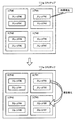
図4では例として、コア3台分のライセンスが設定されているものとする。そして、このようなライセンスの設定状況に従い、図4の上段に示すように、CPUチップ111a内の4つのコアのうち、コア#0,#1,#2が動作中であり、コア#3が動作していないものとする。
In FIG. 4, it is assumed that licenses for three cores are set as an example. Then, according to such license setting status, as shown in the upper part of FIG. 4, among the four cores in the
ここで例として、サーバ装置100は、コア#1のスレッド#2から故障を検知したものとする。この場合、サーバ装置100は、故障が検知されたスレッド#2を、動作していない他のスレッドに置き換えて、スレッド#2で実行されていた処理を置き換え後のスレッドに引き継がせる。
Here, as an example, it is assumed that the server apparatus 100 detects a failure from the
スレッドの置き換え方法としては、故障が検知されたスレッド#2を、他のコア内の動作していないスレッドに置き換える方法が考えられる。図4の下段は、故障が検知されたスレッド#2を、コア#3内の動作していないスレッド#6に置き換えた例を示している。しかしながら、この方法では、スレッド#3を用いた処理はそのまま続行されるので、コア#1が使用された状態のままコア#3が新たに使用されることになる。これにより、使用されるコアの数が「3」から「4」に増加してしまい、ライセンス超過の状態になってしまう。
As a method for replacing a thread, a method is conceivable in which the
これに対して、本実施の形態では、次の図5に示すようなハードウェアの置き換え処理が行われることで、ライセンス超過の発生が防止される。図5は、第2の実施の形態におけるスレッド故障時の処理例を示す図である。 On the other hand, in the present embodiment, the occurrence of excess licenses is prevented by performing hardware replacement processing as shown in FIG. FIG. 5 is a diagram illustrating a processing example when a thread failure occurs in the second embodiment.
図5の上段は、図4の上段と同様の状態を示しており、この状態からコア#1のスレッド#2から故障が検知されたものとする。このとき、サーバ装置100は、コア#1内の他のスレッド#3から故障が検知されていなくても、コア#1を動作禁止状態にする。これとともに、サーバ装置100は、動作していない他のいずれかのコアの動作を開始させる。図5の例では、動作していなかったコア#3の動作が開始され、図5の下段はこのときの状態を示す。この場合、サーバ装置100は、スレッド#2で実行されていた処理を、例えばスレッド#6に引き継がせ、スレッド#3で実行されていた処理を、例えばスレッド#7に引き継がせる。
The upper part of FIG. 5 shows the same state as the upper part of FIG. 4, and it is assumed that a failure is detected from
このような置き換え処理によれば、置き換え処理の前後で、動作中のコアの数は「3」のまま変化せず、ライセンス超過は発生しない。
次に、サーバ装置100の処理の詳細について説明する。
According to such a replacement process, the number of operating cores remains “3” before and after the replacement process, and no license excess occurs.
Next, details of the processing of the server apparatus 100 will be described.
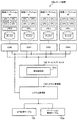
まず、図6は、情報処理装置が備える機能の構成例を示すブロック図である。サーバ装置100は、ハイパーバイザ130およびドメイン管理部140を備える。また、サーバ装置100の記憶装置には、コア管理テーブル151およびドメイン管理テーブル152が記憶される。
First, FIG. 6 is a block diagram illustrating a configuration example of functions provided in the information processing apparatus. The server device 100 includes a hypervisor 130 and a
ここで、ハイパーバイザ130の処理は、サーバ装置100が備えるプロセッサがハイパーバイザプログラムを実行することで実現される。また、ドメイン管理部140の処理は、サーバ装置100が備えるプロセッサがドメイン管理プログラムを実行することで実現される。ハイパーバイザプログラムおよびドメイン管理プログラムは、例えば、いずれかのビルディングブロックに搭載された少なくとも1つのCPUチップによって実行される。
Here, the processing of the hypervisor 130 is realized by a processor included in the server device 100 executing a hypervisor program. The processing of the
サーバ装置100は、1つ以上の仮想マシンを構築する。図6に示す論理ドメイン#0〜#3は、それぞれが仮想マシンに対応し、論理ドメイン#0〜#3のそれぞれには、仮想的なハードウェア資源としてCPU、メモリ、ディスク(不揮発性記憶装置)などが割り当てられる。ここで、各論理ドメインに割り当てられる仮想CPUは、コア内のスレッドに対応する。また、各論理ドメインには、複数の仮想CPUが割り当てられてもよい。
The server apparatus 100 constructs one or more virtual machines. Each of
そして、各論理ドメインにおいては、割り当てられた1つ以上の仮想CPU、すなわち1つ以上のスレッドが、ゲストOSプログラムを実行する。これにより、各論理ドメインにおいてそれぞれ個別のゲストOSが動作する。図6の例では、論理ドメイン#0,#1,#2,#3において、それぞれゲストOS#0,#1,#2,#3が動作する。
In each logical domain, one or more assigned virtual CPUs, that is, one or more threads, execute the guest OS program. Thereby, each guest OS operates in each logical domain. In the example of FIG. 6,
ハイパーバイザ130は、ゲストOS#0〜#3に対して、実ハードウェアへのインタフェースを提供する。これによりゲストOS#0〜#3は、ハイパーバイザ130上で動作する。
The hypervisor 130 provides an interface to the actual hardware for the
また、ハイパーバイザ130は、ハードウェアの異常を検知する異常検知部131を備える。異常検知部131は、少なくとも、コア内のスレッドごとに個別のハードウェア(本実施の形態では命令バッファおよびレジスタ部)の異常発生を検知することができる。
Further, the hypervisor 130 includes an
ドメイン管理部140は、コア管理テーブル151およびドメイン管理テーブル152を利用して、各論理ドメインに対する実ハードウェアの割り当てを管理する。コア管理テーブル151には、コアのライセンスに関する情報が登録される。また、ドメイン管理テーブル152には、論理ドメインごとのスレッドの割り当て状況に関する情報が登録される。
The
また、ドメイン管理部140は、ゲストOSの動作を停止させずに、ゲストOSに対応する論理ドメインからのハードウェア資源の切り離しや、論理ドメインへのハードウェア資源の組み込みを行うための「動的再構成(Dynamic Reconfiguration)」の制御を行う。ドメイン管理部140は、スレッドの異常が検知された場合に、異常が検知されたスレッドが割り当てられているゲストOSに対して、スレッドの切り離しおよび新たなスレッドの組み込みを指示する。
Further, the
図7は、コア管理テーブルに登録される情報の例を示す図である。コア管理テーブル151には、ライセンスありのコア数、ライセンスなしのコア数、および異常コア数が登録される。 FIG. 7 is a diagram illustrating an example of information registered in the core management table. In the core management table 151, the number of licensed cores, the number of unlicensed cores, and the number of abnormal cores are registered.
ライセンスありのコア数は、ユーザによって購入されたコアのライセンス数を示す。コア管理テーブル151において、ライセンスありのコア数の欄は、さらに、ドメイン割り当て済みコア数と、ドメイン未割り当てのコア数とに分けられている。ドメイン割り当て済みのコア数は、論理ドメインに割り当てられているコアの数を示し、ドメイン未割り当てのコア数は、論理ドメインに割り当てられていないコアの数を示す。ドメイン割り当て済みのコア数およびドメイン未割り当てのコア数の各欄に登録された数の合計値が、ユーザによって購入されたライセンスの総数を示す。 The number of cores with a license indicates the number of core licenses purchased by the user. In the core management table 151, the number of cores with license field is further divided into the number of cores assigned to the domain and the number of cores not assigned to the domain. The number of cores assigned to the domain indicates the number of cores assigned to the logical domain, and the number of cores not assigned to the domain indicates the number of cores not assigned to the logical domain. The total value of the numbers registered in the respective fields of the number of cores assigned to the domain and the number of cores not assigned to the domain indicates the total number of licenses purchased by the user.
異常コア数は、サーバ装置100に搭載されたコアのうち、異常が検知されて他のコアに置き換えられたコアの数を示す。ライセンスなしのコア数は、サーバ装置100に搭載されたコアの総数から、購入されたライセンスの数と、異常コア数とを減算した数を示す。従って、コア管理テーブル151のすべての欄に登録されたコア数を合計した値は、サーバ装置100に搭載された、ライセンス設定対象のコアの総数を示す。 The number of abnormal cores indicates the number of cores that have been detected in the server apparatus 100 and have been replaced with other cores. The number of cores without a license indicates the number obtained by subtracting the number of purchased licenses and the number of abnormal cores from the total number of cores mounted on the server apparatus 100. Therefore, the total value of the number of cores registered in all the columns of the core management table 151 indicates the total number of license setting target cores installed in the server apparatus 100.
サーバ装置100が出荷される段階では、例えば、ドメイン未割り当てのコア数の欄に、ユーザによって購入されたライセンスの数が登録される。これとともに、ライセンスなしのコア数の欄に、ライセンス設定対象のコアの総数から、購入されたライセンス数を減算した値が登録される。このとき、ドメイン割り当て済みのコア数および異常コア数の各欄には、「0」が登録される。 At the stage where the server apparatus 100 is shipped, for example, the number of licenses purchased by the user is registered in the field of the number of cores not assigned to a domain. At the same time, a value obtained by subtracting the number of purchased licenses from the total number of cores subject to license setting is registered in the column for the number of unlicensed cores. At this time, “0” is registered in each column of the number of cores assigned to the domain and the number of abnormal cores.
ドメイン管理部140は、例えばサーバ装置100に接続された管理端末(図示せず)からの入力に応じて、論理ドメインの設定を行う。ドメイン管理部140は、論理ドメインにスレッドを割り当てる際、そのスレッドを含むコア内の他のいずれのスレッドも論理ドメインに割り当てられていない場合には、ドメイン割り当て済みのコア数に「1」を加算するとともに、ドメイン未割り当てのコア数から「1」を減算する。
For example, the
また、ユーザによってライセンスが追加購入されたとき、ドメイン管理部140は、追加されたライセンス数の入力を受ける。ドメイン管理部140は、入力された追加ライセンス数を、ドメイン未割り当てのコア数に加算するとともに、同じ追加ライセンス数を、ライセンスなしのコア数から減算する。これにより、ユーザが使用できるコアの数が追加ライセンスの数だけ増加する。
When a license is additionally purchased by the user, the
さらに、ドメイン管理部140は、スレッドの異常を検知したとき、上記のように、異常が検知されたスレッドを含むコアを、他のコアに置き換える。異常が検知されたスレッドがいずれかの論理ドメインに割り当て済みであった場合、ドメイン管理部140は、ドメイン割り当て済みのコア数から「1」を減算するとともに、異常コア数に「1」を加算する。
Furthermore, when detecting an abnormality of a thread, the
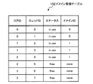
図8は、ドメイン管理テーブルに登録される情報の例を示す図である。ドメイン管理テーブル152には、コアIDおよびスレッドIDに対応付けて、ステータスおよびドメインIDが登録される。 FIG. 8 is a diagram illustrating an example of information registered in the domain management table. In the domain management table 152, a status and a domain ID are registered in association with the core ID and the thread ID.
コアIDは、ライセンス設定対象のコアを識別するための情報である。スレッドIDは、対応するコアに含まれるスレッドを識別するための情報である。
ステータスは、対応するスレッドの状態を示す。ステータスの欄には、「in use」,「free」,「fail」のいずれかが登録される。「in use」は、対応するスレッドに論理ドメインが割り当てられていることを示す。「free」は、対応するスレッドに論理ドメインが割り当てられていないことを示す。「fail」は、対応するスレッドから異常が検出され、そのスレッドに対する論理ドメインの割り当てが禁止されていることを示す。
The core ID is information for identifying a core for which a license is set. The thread ID is information for identifying a thread included in the corresponding core.
The status indicates the state of the corresponding thread. One of “in use”, “free”, and “fail” is registered in the status column. “In use” indicates that a logical domain is assigned to the corresponding thread. “Free” indicates that a logical domain is not allocated to the corresponding thread. “Fail” indicates that an abnormality is detected from the corresponding thread, and assignment of a logical domain to the thread is prohibited.
ドメイン管理部140は、2つのスレッドのうち少なくとも一方のステータスが「in use」であるコアを、コア管理テーブル151におけるドメイン割り当て済みのコアの1つとしてカウントする。また、2つのスレッドのステータスがいずれも「free」であるコアは、コア管理テーブル151におけるドメイン未割り当てのコアまたはライセンスなしのコアのいずれかとしてカウントされる。
The
ドメインIDの欄には、対応するスレッドに割り当てられた論理ドメインの識別番号が登録される。また、対応するスレッドに論理ドメインが割り当てられていない場合、ドメインIDの欄には「none」が登録される。 In the domain ID column, the identification number of the logical domain assigned to the corresponding thread is registered. If no logical domain is assigned to the corresponding thread, “none” is registered in the domain ID column.
ドメイン管理部140は、管理端末などからの要求に応じて論理ドメインを設定する際や、スレッドの異常が検知された場合などに、ドメイン管理テーブル152におけるステータスおよびドメインIDの各欄を更新する。
The
なお、以上のコア管理テーブル151およびドメイン管理テーブル152は、例えば、前述したハイパーバイザプログラムおよびドメイン管理プログラムが実行されるCPUチップが搭載されたビルディングブロック内のHDDに格納され、同じビルディングブロック内のメモリに展開される。 The core management table 151 and the domain management table 152 described above are stored in, for example, the HDD in the building block on which the CPU chip on which the hypervisor program and the domain management program described above are executed and stored in the same building block. Expanded into memory.
次に、異常が検知されたスレッドを他のスレッドに置き換える際のサーバ装置100の処理について、フローチャートを用いて説明する。図9および図10は、スレッドの置き換え処理の例を示すフローチャートである。 Next, processing of the server device 100 when replacing a thread in which an abnormality is detected with another thread will be described with reference to a flowchart. 9 and 10 are flowcharts illustrating an example of thread replacement processing.
[ステップS11]異常検知部131は、論理ドメインが割り当てられているいずれかのスレッドから異常を検知すると、その旨をドメイン管理部140に通知する。これにより、ステップS12以降の処理が開始される。
[Step S11] When the
[ステップS12]サーバ装置100には、コア単位での置き換えを行うか否かを示す情報があらかじめ設定されている。この情報は、ユーザの操作によって、例えば管理端末からサーバ装置100に入力される。この情報は、例えば、前述のドメイン管理プログラムと同じ不揮発性記憶装置に格納される。 [Step S12] In the server apparatus 100, information indicating whether or not to perform replacement in units of cores is set in advance. This information is input to the server apparatus 100 from the management terminal, for example, by a user operation. This information is stored in, for example, the same non-volatile storage device as the domain management program described above.
スレッドの異常が検知されたことの通知を受けたドメイン管理部140は、設定された上記の情報に基づき、コア単位で置き換えを行うか否かを判定する。コア単位で置き換えを行う場合にはステップS13の処理が実行され、行わない場合には図10のステップS21の処理が実行される。
The
[ステップS13]ドメイン管理部140は、コア管理テーブル151に基づき、ライセンスなしのコアが存在するかを判定する。ライセンスなしのコアが存在する場合にはステップS14の処理が実行され、存在しない場合には図10のステップS21の処理が実行される。
[Step S13] Based on the core management table 151, the
[ステップS14]ドメイン管理部140は、ステップS11で異常が検知されたスレッドの切り離し処理を行う。後述するように、ドメイン管理部140は、異常が検知されたスレッドに割り当てられていた論理ドメインで動作するゲストOSに対して、そのスレッドの切り離しを指示する。また、ドメイン管理部140は、ドメイン管理テーブル152において、異常が検知されたスレッドに対応するステータスを「in use」から「fail」に更新するとともに、そのスレッドに対応するドメインIDの欄を「none」に更新する。
[Step S14] The
[ステップS15]ドメイン管理部140は、ドメイン管理テーブル152に基づき、2つのスレッドのどちらにも論理ドメインが割り当てられていないコアを選択する。ドメイン管理部140は、選択したコアからスレッドを1つ選択し、選択したスレッドの組み込み処理を行う。
[Step S15] Based on the domain management table 152, the
ドメイン管理部140は、ドメイン管理テーブル152において、選択したスレッドに対応するステータスを「free」から「in use」に更新するとともに、そのスレッドに対応するドメインIDの欄に、異常が検知されたスレッドに割り当てられていた論理ドメインのIDを登録する。また、後述するように、ドメイン管理部140は、異常が検知されたスレッドに割り当てられていた論理ドメインで動作するゲストOSに対して、選択したスレッドの組み込みを指示する。
In the domain management table 152, the
[ステップS16]ドメイン管理部140は、ドメイン管理テーブル152に基づき、異常が検知されたスレッドを含むコア内の他方のスレッドに、論理ドメインが割り当てられているかを判定する。他方のスレッドに論理ドメインが割り当てられている場合にはステップS17の処理が実行され、割り当てられていない場合にはステップS19の処理が実行される。
[Step S16] Based on the domain management table 152, the
[ステップS17]ドメイン管理部140は、他方のスレッドの切り離し処理を行う。基本的な処理手順はステップS14と同様であり、ドメイン管理部140は、他方のスレッドに割り当てられていた論理ドメインで動作するゲストOSに対して、そのスレッドの切り離しを指示する。また、ドメイン管理部140は、ドメイン管理テーブル152において、他方のスレッドに対応するステータスを「in use」から「free」に更新するとともに、そのスレッドに対応するドメインIDの欄を「none」に更新する。
[Step S17] The
[ステップS18]ドメイン管理部140は、ステップS15で選択したコア内のスレッドのうち、ステップS15で選択していない他方のスレッド(以下、「非選択のスレッド」と呼ぶ)の組み込み処理を行う。基本的な処理手順はステップS15と同様であり、ドメイン管理部140は、ドメイン管理テーブル152において、非選択のスレッドに対応するステータスを「free」から「in use」に更新するとともに、そのスレッドに対応するドメインIDの欄に、ステップS17で切り離したスレッドに割り当てられていた論理ドメインのIDを登録する。また、後述するように、ドメイン管理部140は、ステップS17で切り離したスレッドに割り当てられていた論理ドメインで動作するゲストOSに対して、非選択のスレッドの組み込みを指示する。
[Step S18] The
[ステップS19]ドメイン管理部140は、コア管理テーブル151における異常コア数に「1」を加算するとともに、ライセンスなしのコア数から「1」を減算する。これによりコアの置き換え処理が完了し、各論理ドメインの通常の運用が続行される。
[Step S19] The
以上のステップS14〜S19の処理によれば、異常が検知されたスレッドを含むコアが、他のコアに置き換えられる。この場合、動作中のコアの数は変化しないため、ライセンス超過が発生することなく、異常が検知されたスレッドを置き換えることができる。 According to the processes in steps S14 to S19 described above, the core including the thread in which the abnormality is detected is replaced with another core. In this case, since the number of operating cores does not change, a thread in which an abnormality is detected can be replaced without causing an excess of licenses.
[ステップS21]サーバ装置100には、スレッド単位での置き換えを行うか否かを示す情報があらかじめ設定されている。この情報は、ユーザの操作によって、例えば管理端末からサーバ装置100に入力される。この情報は、例えば、前述のドメイン管理プログラムと同じ不揮発性記憶装置に格納される。 [Step S21] In the server apparatus 100, information indicating whether or not to perform replacement in units of threads is set in advance. This information is input to the server apparatus 100 from the management terminal, for example, by a user operation. This information is stored in, for example, the same non-volatile storage device as the domain management program described above.
ドメイン管理部140は、設定された上記の情報に基づき、スレッド単位で置き換えを行うか否かを判定する。スレッド単位で置き換えを行う場合にはステップS22の処理が実行され、行わない場合にはステップS25の処理が実行される。
The
[ステップS22]ドメイン管理部140は、ドメイン管理テーブル152に基づき、ステータスが「free」であるスレッド、すなわち、論理ドメインが未割り当てであり、かつ異常が検知されていないスレッドが存在するかを判定する。ステータスが「free」のコアが存在する場合にはステップS23の処理が実行され、存在しない場合にはステップS25の処理が実行される。
[Step S22] Based on the domain management table 152, the
[ステップS23]ドメイン管理部140は、ステップS11で異常が検知されたスレッドの切り離し処理を行う。この処理はステップS14と同じであるので、説明を省略する。
[Step S23] The
[ステップS24]ドメイン管理部140は、ドメイン管理テーブル152に基づき、ステータスが「free」であるスレッドを選択し、選択したスレッドの組み込み処理を行う。
[Step S24] The
基本的な処理手順はステップS15と同様であり、ドメイン管理部140は、ドメイン管理テーブル152において、選択したスレッドに対応するステータスを「free」から「in use」に更新するとともに、そのスレッドに対応するドメインIDの欄に、異常が検知されたスレッドに割り当てられていた論理ドメインのIDを登録する。また、ドメイン管理部140は、異常が検知されたスレッドに割り当てられていた論理ドメインで動作するゲストOSに対して、選択したスレッドの組み込みを指示する。
The basic processing procedure is the same as in step S15, and the
これによりスレッド置き換え処理が完了し、各論理ドメインの通常の運用が続行される。
以上のステップS23,S24の処理によれば、異常が検知されたスレッドが、すでに一方のスレッドに論理ドメインが割り当てられていたコアにおける他方のスレッドに置き換えられる。この場合、動作中のコアの数は増加しないため、ライセンス超過が発生することなく、異常が検知されたスレッドを置き換えることができる。
As a result, the thread replacement process is completed, and the normal operation of each logical domain is continued.
According to the processing in steps S23 and S24 described above, the thread in which the abnormality is detected is replaced with the other thread in the core in which the logical domain has already been assigned to one thread. In this case, since the number of operating cores does not increase, a thread in which an abnormality is detected can be replaced without causing an excess of licenses.
[ステップS25]ドメイン管理部140は、ステップS11で異常が検知されたスレッドの切り離し処理を行う。この処理はステップS14,S23と同じであるので、説明を省略する。
[Step S25] The
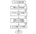
図11は、スレッド切り離し処理の例を示すフローチャートである。この図11の処理は、図9のステップS14,S17、図10のステップS23,S25に対応する。
[ステップS31]ドメイン管理部140は、切り離し対象のスレッドのIDを決定する。
FIG. 11 is a flowchart illustrating an example of thread separation processing. The process of FIG. 11 corresponds to steps S14 and S17 of FIG. 9 and steps S23 and S25 of FIG.
[Step S31] The
[ステップS32]ドメイン管理部140は、切り離し対象のスレッドに割り当てられていた論理ドメインで動作するゲストOSに対して、切り離し対象のスレッドのIDを通知して、スレッドの切り離しを指示する。
[Step S32] The
[ステップS33]切り離し指示を受けたゲストOSは、切り離し対象のスレッドを用いて実行されている処理を、自身に割り当てられている他のスレッドに引き継がせる。また、ゲストOSは、切り離し対象のスレッドを、自身が使用しない状態に移行させる。以上の処理が完了すると、ゲストOSは、ハイパーバイザ130に対して、切り離し対象のスレッドの停止を依頼する。 [Step S33] Upon receiving the disconnection instruction, the guest OS causes the other thread assigned to itself to take over the process being executed using the thread to be disconnected. Further, the guest OS shifts the thread to be detached to a state where it is not used by itself. When the above processing is completed, the guest OS requests the hypervisor 130 to stop the thread to be detached.
[ステップS34]ドメイン管理部140は、切り離し対象のスレッドの停止依頼を、ハイパーバイザ130を介して受け付ける。ドメイン管理部140は、ドメイン管理テーブル152において、切り離し対象のスレッドに対応するステータスを「in use」から「fail」に更新するとともに、そのスレッドに対応するドメインIDの欄を「none」に更新する。
[Step S <b> 34] The
図12は、スレッド組み込み処理の例を示すフローチャートである。この図12の処理は、図9のステップS15,S18、図10のステップS24に対応する。
[ステップS41]ドメイン管理部140は、組み込み対象のスレッドのIDを決定する。
FIG. 12 is a flowchart illustrating an example of thread incorporation processing. The processing in FIG. 12 corresponds to steps S15 and S18 in FIG. 9 and step S24 in FIG.
[Step S41] The
[ステップS42]ドメイン管理部140は、ドメイン管理テーブル152において、組み込み対象のスレッドに対応するステータスを「free」から「in use」に更新するとともに、そのスレッドに対応するドメインIDの欄に、置き換え前のスレッドに割り当てられていた論理ドメインのIDを登録する。
[Step S42] In the domain management table 152, the
[ステップS43]ドメイン管理部140は、組み込み対象のスレッドに新たに割り当てた論理ドメインで動作するゲストOSに対して、組み込み対象のスレッドのIDを通知して、スレッドの組み込みを指示する。
[Step S43] The
[ステップS44]組み込み指示を受けたゲストOSは、ハイパーバイザ130に対して、組み込み対象のスレッドの動作開始を依頼する。また、ゲストOSは、組み込み対象のスレッドのレジスタ、TLB(Translation Lookaside Buffer)などの初期化処理を行う。 [Step S44] The guest OS that received the installation instruction requests the hypervisor 130 to start the operation of the thread to be installed. In addition, the guest OS performs initialization processing such as a register of a thread to be embedded and a TLB (Translation Lookaside Buffer).
[ステップS45]ゲストOSは、組み込み対象のスレッドに処理を割り当てる。
次に、コア単位の置き換えを行った場合における管理テーブルの遷移例を挙げる。図13は、コア管理テーブルの遷移の例を示す図である。また、図14は、ドメイン管理テーブルの遷移の例を示す図である。
[Step S45] The guest OS assigns processing to a thread to be embedded.
Next, a transition example of the management table when the core unit is replaced will be described. FIG. 13 is a diagram illustrating an example of transition of the core management table. FIG. 14 is a diagram illustrating an example of transition of the domain management table.
図13および図14の例では、サーバ装置100は、それぞれ2つのスレッドを含む8つのコアを備えるものとする。そして、コア6台分のライセンスが設定されたものとする。初期状態では、図13の上段に示すように、コア管理テーブル151における異常コア数は「0」であり、ライセンスなしのコア数は「2」である。 In the example of FIGS. 13 and 14, the server apparatus 100 includes eight cores each including two threads. It is assumed that licenses for six cores are set. In the initial state, as shown in the upper part of FIG. 13, the number of abnormal cores in the core management table 151 is “0”, and the number of unlicensed cores is “2”.
また、図14に示すように、スレッドに異常が発生する前の状態では、スレッド#0〜#4に対して論理ドメインが割り当てられ、その他のスレッドには論理ドメインが割り当てられていないものとする。この場合、コア#0〜#2が動作状態となるので、コア管理テーブル151においては、ドメイン割り当て済みのコア数が「3」となり、ドメイン未割り当てのコア数も「3」となる。
Further, as shown in FIG. 14, in the state before an abnormality occurs in a thread, a logical domain is assigned to
この状態から、例としてスレッド#2から異常が検知されたものとする。コア単位での置き換えを行う場合、ドメイン管理部140は、ドメイン管理テーブル152において、スレッド#2に対応するステータスを「in use」から「fail」に更新する。また、ドメイン管理部140は、スレッド#3に対応するステータスを「in use」から「free」に更新する。さらに、ドメイン管理部140は、スレッド#2,#3にそれぞれ対応するドメインIDの欄を、ともに「1」から「none」に更新する。これにより、論理ドメイン#1からスレッド#2,#3が切り離され、スレッド#2,#3が含まれるコア#1の動作が禁止される。
Assume that an abnormality is detected from
また、ドメイン管理部140は、2つのスレッドがともに「free」であるコアとして、例えばコア#3を選択する。この場合、ドメイン管理部140は、コア#3に含まれるスレッド#6,#7に対応するステータスを、ともに「free」から「in use」に更新する。また、ドメイン管理部140は、スレッド#6に対応するドメインIDの欄に、スレッド#2に割り当てられていた論理ドメインを示すドメインID「1」を登録する。さらに、ドメイン管理部140は、スレッド#7に対応するドメインIDの欄に、スレッド#3に割り当てられていた論理ドメインを示すドメインID「1」を登録する。これにより、スレッド#6,#7が論理ドメイン#1に組み込まれる。
Further, the
このとき、ドメイン管理部140は、コア管理テーブル151における異常コア数に「1」を加算するとともに、ライセンスなしのコア数から「1」を減算する。この場合、ライセンスありのコア数、すなわち、論理ドメインが割り当て済みのコア数と論理ドメインが未割り当てのコア数との合計は、「6」のまま変化しない。すなわち、ライセンス超過を発生させることなく、異常スレッドを他の正常なスレッドに置き換えることが可能になる。
At this time, the
〔第3の実施の形態〕
図15は、第3の実施の形態に係る情報処理装置が備える機能の構成例を示すブロック図である。
[Third Embodiment]
FIG. 15 is a block diagram illustrating a configuration example of functions provided in the information processing apparatus according to the third embodiment.
図15に示すサーバ装置100aは、第2の実施の形態に係るサーバ装置100を、仮想マシンを構築する代わりに、物理パーティションを設定するように変形したものである。図15に示す物理パーティション#0〜#3には、サーバ装置100aが備えるハードウェアリソースの一部がそれぞれ割り当てられる。ここで、各物理パーティションに割り当てられるCPUは、コア内のスレッドに対応する。また、各物理パーティションには、複数のCPU、すなわち複数のスレッドが割り当てられてもよい。
A server apparatus 100a illustrated in FIG. 15 is obtained by modifying the server apparatus 100 according to the second embodiment so as to set a physical partition instead of constructing a virtual machine. Some of the hardware resources included in the server apparatus 100a are allocated to the
そして、各物理パーティションにおいては、割り当てられた1つ以上のCPU、すなわち1つ以上のスレッドが、OSプログラムを実行する。これにより、各物理パーティションにおいてそれぞれ個別のOSを動作させることができる。図15の例では、物理パーティション#0,#1,#2,#3において、それぞれOS#0,#1,#2,#3が動作する。
In each physical partition, one or more assigned CPUs, that is, one or more threads, execute the OS program. Thereby, each OS can be operated in each physical partition. In the example of FIG. 15,
サーバ装置100aは、システム管理部150を備える。システム管理部150の処理は、第2の実施の形態におけるドメイン管理部140の処理に対応する。なお、システム管理部150の処理は、サーバ装置100aが備えるプロセッサがシステム管理プログラムを実行することで実現される。システム管理プログラムは、例えば、いずれかのビルディングブロックに搭載された少なくとも1つのCPUチップによって実行される。
The server apparatus 100a includes a system management unit 150. The processing of the system management unit 150 corresponds to the processing of the
また、サーバ装置100aの記憶装置には、コア管理テーブル151およびパーティション管理テーブル152aが記憶される。コア管理テーブル151に登録される情報は、第2の実施の形態と同様である。パーティション管理テーブル152aの構成は、図8のドメイン管理テーブル152における「ドメインID」を「パーティションID」に置き換えた構成となる。すなわち、パーティション管理テーブル152aにおいて、それぞれ個別のOSが動作するパーティションに対するスレッドの割り当てが管理される。 In addition, the core management table 151 and the partition management table 152a are stored in the storage device of the server device 100a. Information registered in the core management table 151 is the same as that in the second embodiment. The configuration of the partition management table 152a is a configuration in which “domain ID” in the domain management table 152 of FIG. 8 is replaced with “partition ID”. That is, in the partition management table 152a, the thread assignment to the partition on which each individual OS operates is managed.
サービスプロセッサ120の処理は、サービスプロセッサ120のCPU121(図3参照)が所定のファームウェアプログラムを実行することで実現される。サービスプロセッサ120は、異常検知部131aを備える。異常検知部131aは、第2の実施の形態の異常検知部131と同様に、コア内のスレッドごとに個別のハードウェアの異常発生を検知することができる
以上のサーバ装置100aにおいては、第2の実施の形態におけるハイパーバイザ130、ドメイン管理部140およびゲストOSとの間の処理が、サービスプロセッサ120、システム管理部150およびOSとの間で実行される。すなわち、第3の実施の形態では、図9〜図12に示した処理が、ハイパーバイザ130をサービスプロセッサ120に、ドメイン管理部140をシステム管理部150に、ゲストOSをOSにそれぞれ置き換えることで実現される。これにより、第3の実施の形態でも、スレッドに異常が発生した場合に、ライセンス超過を発生させることなく、異常が発生したスレッドを他の正常なスレッドに置き換えることができる。
The processing of the
〔他のハードウェア資源の置き換え処理例〕
上記の第2,第3の実施の形態では、コアに対してライセンスを設定した場合について説明したが、例えば、サーバ装置が備える他のハードウェア資源に対してライセンスが設定されてもよい。
[Example of replacement processing of other hardware resources]
In the second and third embodiments described above, the case where a license is set for a core has been described. However, for example, a license may be set for another hardware resource included in the server device.
ここでは、サーバ装置に搭載されたメモリ装置に対してライセンスが設定される場合について説明する。サーバ装置は、複数のメモリ装置を有しており、メモリ装置を単位としてライセンスが設定される。また、例えば、第2の実施の形態における論理ドメインごと、あるいは、第3の実施の形態における物理パーティションごとに、各メモリ装置の記憶領域を分割した分割領域を単位としてメモリ資源が割り当てられるものとする。そして、第2の実施の形態における異常検知部131、あるいは第3の実施の形態における異常検知部131aは、上記の分割領域ごとに異常を検知できるものとする。
Here, a case where a license is set for a memory device mounted on a server device will be described. The server device has a plurality of memory devices, and a license is set for each memory device. Also, for example, a memory resource is allocated for each logical domain in the second embodiment or for each physical partition in the third embodiment in units of divided areas obtained by dividing the storage area of each memory device. To do. And the
図16は、メモリ装置に対するライセンス設定の第1の例を示す図である。図16に示すビルディングブロック110には、複数のメモリモジュール310が搭載されている。メモリモジュール310は、例えば、DIMM(Dual Inline Memory Module)規格などに準拠した基板である。また、メモリモジュール310のそれぞれには、複数のメモリチップ320が搭載されている。
FIG. 16 is a diagram illustrating a first example of license setting for a memory device. A plurality of
なお、ビルディングブロックは、図2に示したビルディングブロック110a〜110dのそれぞれに対応する。また、1つまたは複数のメモリモジュール310は、図2に示したメモリ112a,112bのいずれかに対応する。
The building blocks correspond to the
図16において、例えば、メモリモジュール310が上記のメモリ装置に対応し、メモリモジュール310内の各メモリチップ320が、上記の分割領域に対応する。すなわち、サーバ装置は、論理ドメインまたは物理パーティションに対して、メモリチップ320を単位としてメモリ資源を割り当てる。その一方で、メモリモジュール310を単位としてライセンスが設定される。
In FIG. 16, for example, the
サーバ装置は、メモリチップ320ごとに異常を監視する。そして、サーバ装置は、論理ドメインまたは物理パーティションに割り当て済みのいずれかのメモリチップ320から異常を検知すると、異常が検知されたメモリチップ320を含むメモリモジュール310の使用を禁止する。これとともに、サーバ装置は、使用を禁止したメモリモジュール310を、使用されていない他のメモリモジュール310(すなわち、内部のすべてのメモリチップ320が論理ドメインまたは物理パーティションに割り当てられていないメモリモジュール310)に置き換え、置き換えたメモリモジュール310の使用を開始する。
The server device monitors the abnormality for each
このような処理により、メモリチップ320の異常が発生した場合でも、ライセンス超過を起こすことなく、メモリチップ320を置き換えることができる。
なお、図16の例では、メモリモジュール310を単位としてライセンスを設定したが、他の例として、同一メモリモジュール310内の隣接する複数個のメモリチップ310を単位としてライセンスが設定されてもよい。この場合、隣接する複数個のメモリチップ310の合計記憶容量を単位としてライセンスが設定されてもよい。
By such processing, even when an abnormality occurs in the
In the example of FIG. 16, the license is set for each
図17は、メモリ装置に対するライセンス設定の第2の例を示す図である。図17の例は、上記のメモリ装置をメモリモジュール310内のメモリチップ320とし、上記の分割領域を、メモリチップ320のメモリ領域を例えば均等の容量で分割した部分領域330としたものである。
FIG. 17 is a diagram illustrating a second example of license setting for the memory device. In the example of FIG. 17, the memory device is the
図17の例では、サーバ装置は、論理ドメインまたは物理パーティションに対して、部分領域330を単位としてメモリ資源を割り当てる。その一方で、メモリチップ320を単位としてライセンスが設定される。
In the example of FIG. 17, the server device allocates memory resources in units of
サーバ装置は、論理ドメインまたは物理パーティションに割り当て済みのいずれかの部分領域330から異常を検知すると、異常が検知された部分領域330を含むメモリチップ320の使用を禁止する。これとともに、サーバ装置は、使用を禁止したメモリチップ320を、使用されていない他のメモリチップ320に置き換え、置き換えたメモリチップ320の使用を開始する。
When the server apparatus detects an abnormality from any of the
このような処理により、部分領域330の異常が発生した場合でも、ライセンス超過を起こすことなく、部分領域330を置き換えることができる。
以上の各実施の形態に関し、さらに以下の付記を開示する。
By such processing, even when an abnormality occurs in the
Regarding the above embodiments, the following supplementary notes are further disclosed.
(付記1) 複数の処理を並列に実行可能であって、並列に実行する処理ごとに個別に設けられた個別回路を有する演算回路を、複数備えた情報処理装置において、
前記演算回路を単位として設定された使用権の数を記憶する記憶部と、
複数の前記演算回路のうち、前記使用権の数の前記演算回路の動作を許可するとともに、動作中の前記演算回路に搭載されたいずれかの前記個別回路の異常を検知すると、異常が検知された前記個別回路が搭載された前記演算回路における他の前記個別回路の動作を停止させ、動作していないいずれかの前記演算回路の動作を開始させる制御部と、
を有することを特徴とする情報処理装置。
(Supplementary Note 1) In an information processing apparatus that can execute a plurality of processes in parallel and includes a plurality of arithmetic circuits each having an individual circuit provided for each process to be executed in parallel.
A storage unit that stores the number of usage rights set in units of the arithmetic circuit;
Among the plurality of arithmetic circuits, the operation of the arithmetic circuit for the number of usage rights is permitted, and an abnormality is detected when an abnormality of any of the individual circuits mounted on the arithmetic circuit in operation is detected. A controller that stops operation of the other individual circuit in the arithmetic circuit on which the individual circuit is mounted, and starts operation of any of the arithmetic circuits that are not operating;
An information processing apparatus comprising:
(付記2) 前記制御部は、動作中の前記演算回路に搭載されたいずれかの前記個別回路の異常を検知したとき、動作していない前記演算回路が存在しない場合には、動作中の前記演算回路の中に使用されていない前記個別回路があるかを判定し、使用されていない前記個別回路がある場合には、異常が検知された前記個別回路を用いて実行されていた処理を、使用されていない前記個別回路を用いて実行させることを特徴とする付記1記載の情報処理装置。
(Additional remark 2) When the said control part detects abnormality of any said individual circuit mounted in the said arithmetic circuit in operation, when the said arithmetic circuit which is not operating does not exist, the said operational circuit It is determined whether there is the individual circuit that is not used in the arithmetic circuit, and when there is the individual circuit that is not used, the processing that has been performed using the individual circuit in which an abnormality is detected, The information processing apparatus according to
(付記3) 前記記憶部は、動作中の前記演算回路に搭載された前記個別回路のうち、1つまたは複数のオペレーティングシステムのいずれかの処理に割り当てられた前記個別回路の情報を保持する管理情報を記憶し、
前記制御部は、前記管理情報においていずれかのオペレーティングシステムの処理に割り当てられた前記個別回路の異常を検知したとき、動作していない前記演算回路が存在しない場合には、前記管理情報に基づき、動作中の前記演算回路に搭載された前記個別回路の中にいずれのオペレーティングシステムの処理にも割り当てられていない前記個別回路があるかを判定し、いずれのオペレーティングシステムの処理にも割り当てられていない前記個別回路がある場合には、異常が検知された前記個別回路がいずれのオペレーティングシステムにも割り当てられていない前記個別回路に置き換えられるように前記管理情報を更新する、
ことを特徴とする付記1記載の情報処理装置。
(Additional remark 3) The said memory | storage part hold | maintains the information which hold | maintains the information of the said individual circuit allocated to the process of one or several operating systems among the said individual circuits mounted in the said arithmetic circuit in operation | movement. Remember information,
The control unit, when detecting an abnormality of the individual circuit assigned to the processing of any operating system in the management information, if the arithmetic circuit that is not operating does not exist, based on the management information, It is determined whether there is the individual circuit that is not assigned to any operating system processing among the individual circuits mounted on the arithmetic circuit in operation, and is not assigned to any operating system processing If the individual circuit is present, the management information is updated so that the individual circuit in which an abnormality is detected is replaced with the individual circuit that is not assigned to any operating system.
The information processing apparatus according to
(付記4) 前記情報処理装置は、複数のメモリ装置を有し、
前記記憶部は、前記メモリ装置を単位として設定されたメモリ使用権の数を記憶し、
前記制御部は、複数の前記メモリ装置のうち、前記メモリ使用権の数の前記メモリ装置の使用を許可するとともに、使用中の前記メモリ装置の記憶領域を分割した分割領域のいずれかから異常を検知すると、異常が検知された前記分割領域を含む前記メモリ装置における他の前記分割領域の使用を停止させ、使用されていないいずれかの前記メモリ装置の使用を開始する、
ことを特徴とする付記1〜3のいずれか1つに記載の情報処理装置。
(Supplementary Note 4) The information processing apparatus includes a plurality of memory devices,
The storage unit stores the number of memory usage rights set in units of the memory device,
The control unit permits the use of the memory device having the number of memory usage rights among the plurality of memory devices, and detects an abnormality from any of the divided areas obtained by dividing the storage area of the memory device in use. Upon detection, the use of the other divided area in the memory device including the divided area where the abnormality is detected is stopped, and the use of any of the memory devices that are not used is started.
The information processing apparatus according to any one of
(付記5) 複数の処理を並列に実行可能であって、並列に実行する処理ごとに個別に設けられた個別回路を有する演算回路を、複数備えた情報処理装置における制御方法であって、
前記演算回路を単位として設定された使用権の数を記憶する記憶部を参照して、複数の前記演算回路のうち、前記使用権の数の前記演算回路の動作を許可し、
動作中の前記演算回路に搭載されたいずれかの前記個別回路の異常を検知すると、異常が検知された前記個別回路が搭載された前記演算回路における他の前記個別回路の動作を停止させ、動作していないいずれかの前記演算回路の動作を開始させる、
ことを特徴とする制御方法。
(Supplementary Note 5) A control method in an information processing apparatus that is capable of executing a plurality of processes in parallel and includes a plurality of arithmetic circuits each having a separate circuit for each process to be executed in parallel.
With reference to a storage unit that stores the number of usage rights set in units of the arithmetic circuit, among the plurality of arithmetic circuits, the operation of the arithmetic circuit for the number of usage rights is permitted,
When an abnormality is detected in any of the individual circuits mounted on the arithmetic circuit in operation, the operation of the other individual circuit in the arithmetic circuit in which the individual circuit in which the abnormality is detected is stopped is performed. To start the operation of any one of the arithmetic circuits,
A control method characterized by that.
(付記6) 動作中の前記演算回路に搭載されたいずれかの前記個別回路の異常を検知したとき、動作していない前記演算回路が存在しない場合には、動作中の前記演算回路の中に使用されていない前記個別回路があるかを判定し、使用されていない前記個別回路がある場合には、異常が検知された前記個別回路を用いて実行されていた処理を、使用されていない前記個別回路を用いて実行させる、
処理をさらに含むことを特徴とする付記5記載の制御方法。
(Supplementary Note 6) When an abnormality is detected in any of the individual circuits mounted on the operational circuit that is in operation, if the operational circuit that is not operating does not exist, It is determined whether or not there is an individual circuit that is not used, and if there is an individual circuit that is not used, the processing that has been performed using the individual circuit in which an abnormality has been detected is not used. Execute using an individual circuit,
The control method according to
(付記7) 前記記憶部は、動作中の前記演算回路に搭載された前記個別回路のうち、1つまたは複数のオペレーティングシステムのいずれかの処理に割り当てられた前記個別回路の情報を保持する管理情報を記憶し、
前記管理情報においていずれかのオペレーティングシステムの処理に割り当てられた前記個別回路の異常を検知したとき、動作していない前記演算回路が存在しない場合には、前記管理情報に基づき、動作中の前記演算回路に搭載された前記個別回路の中にいずれのオペレーティングシステムの処理にも割り当てられていない前記個別回路があるかを判定し、いずれのオペレーティングシステムの処理にも割り当てられていない前記個別回路がある場合には、異常が検知された前記個別回路がいずれのオペレーティングシステムにも割り当てられていない前記個別回路に置き換えられるように前記管理情報を更新する、
処理をさらに含むことを特徴とする付記5記載の制御方法。
(Additional remark 7) The said memory | storage part hold | maintains the information which hold | maintains the information of the said individual circuit allocated to the process of one or several operating systems among the said individual circuits mounted in the said arithmetic circuit in operation | movement Remember information,
When an abnormality of the individual circuit assigned to any of the operating system processes is detected in the management information, if the arithmetic circuit that is not operating does not exist, the operation that is operating based on the management information It is determined whether there is the individual circuit that is not assigned to any operating system process among the individual circuits mounted on the circuit, and there is the individual circuit that is not assigned to any operating system process. In this case, the management information is updated so that the individual circuit in which an abnormality is detected is replaced with the individual circuit that is not assigned to any operating system.
The control method according to
(付記8) 前記情報処理装置は、複数のメモリ装置を有し、
前記記憶部は、前記メモリ装置を単位として設定されたメモリ使用権の数を記憶し、
複数の前記メモリ装置のうち、前記メモリ使用権の数の前記メモリ装置の使用を許可し、使用中の前記メモリ装置の記憶領域を分割した分割領域のいずれかから異常を検知すると、異常が検知された前記分割領域を含む前記メモリ装置における他の前記分割領域の使用を停止させ、使用されていないいずれかの前記メモリ装置の使用を開始する、
処理をさらに含むことを特徴とする付記5〜7のいずれか1つに記載の制御方法。
(Supplementary Note 8) The information processing apparatus includes a plurality of memory devices,
The storage unit stores the number of memory usage rights set in units of the memory device,
An abnormality is detected when an abnormality is detected from any of the divided areas obtained by dividing the storage area of the memory device in use by permitting the use of the memory device of the number of memory usage rights among the plurality of memory devices. Stopping the use of the other divided areas in the memory device including the divided area, and starting using any of the memory devices that are not used.
The control method according to any one of
1 情報処理装置
2 記憶部
3 制御部
11,12 演算回路
21〜24 個別回路
DESCRIPTION OF
Claims (5)
前記演算回路を単位として設定された使用権の数を記憶する記憶部と、
複数の前記演算回路のうち、前記使用権の数の前記演算回路の動作を許可するとともに、動作中の前記演算回路に搭載された前記複数の個別回路のうち第1の個別回路の異常を検知すると、動作していない前記演算回路が存在する場合には、前記第1の個別回路が搭載された前記演算回路における他の個別回路の動作を停止させ、動作していないいずれかの前記演算回路の動作を開始させ、動作していない前記演算回路が存在しない場合には、動作中の前記演算回路の中に使用されていない第2の個別回路があるかを判定し、前記第2の個別回路がある場合には、前記第1の個別回路を用いて実行されていた処理を、前記第2の個別回路を用いて実行させる制御部と、
を有することを特徴とする情報処理装置。 In an information processing apparatus provided with a plurality of arithmetic circuits each having a plurality of individual circuits that execute processing in parallel,
A storage unit that stores the number of usage rights set in units of the arithmetic circuit;
Among the plurality of arithmetic circuits, the operation of the arithmetic circuit for the number of usage rights is permitted, and an abnormality of the first individual circuit among the plurality of individual circuits mounted on the arithmetic circuit in operation is detected. Then, when there is an arithmetic circuit that is not operating , the operation of another individual circuit in the arithmetic circuit on which the first individual circuit is mounted is stopped, and any of the arithmetic circuits that are not operating When the operation circuit that is not operating does not exist, it is determined whether there is a second individual circuit that is not used in the operation circuit that is operating, and the second individual circuit is determined. If there is a circuit includes a first processing which has been performed using individual circuit, the second control unit which Ru is performed using an individual circuit,
An information processing apparatus comprising:
前記演算回路を単位として設定された使用権の数と、動作中の前記演算回路に搭載された前記複数の個別回路のうち、1つまたは複数のオペレーティングシステムのいずれかの処理に割り当てられた第1の個別回路の情報を保持する管理情報とを記憶する記憶部と、
複数の前記演算回路のうち、前記使用権の数の前記演算回路の動作を許可するとともに、前記第1の個別回路の異常を検知すると、動作していない前記演算回路が存在する場合には、前記第1の個別回路が搭載された前記演算回路における他の個別回路の動作を停止させ、動作していないいずれかの前記演算回路の動作を開始させ、動作していない前記演算回路が存在しない場合には、前記管理情報に基づき、動作中の前記演算回路に搭載された前記複数の個別回路の中にいずれのオペレーティングシステムの処理にも割り当てられていない第2の個別回路があるかを判定し、前記第2の個別回路がある場合には、前記第1の個別回路が前記第2の個別回路に置き換えられるように前記管理情報を更新する制御部と、
を有することを特徴とする情報処理装置。 In an information processing apparatus provided with a plurality of arithmetic circuits each having a plurality of individual circuits that execute processing in parallel,
The number of usage rights set in units of the arithmetic circuit and the number assigned to processing of one or a plurality of operating systems among the plurality of individual circuits mounted on the arithmetic circuit in operation. A storage unit for storing management information for holding information of one individual circuit ;
While permitting operation of the number of usage rights among the plurality of arithmetic circuits and detecting an abnormality of the first individual circuit, when there is the arithmetic circuit not operating, The operation of the other individual circuit in the arithmetic circuit on which the first individual circuit is mounted is stopped, the operation of any of the arithmetic circuits that are not operating is started , and there is no arithmetic circuit that is not operating In this case, based on the management information, it is determined whether there is a second individual circuit that is not allocated to any operating system process among the plurality of individual circuits mounted on the operating arithmetic circuit. When there is the second individual circuit, a control unit that updates the management information so that the first individual circuit is replaced with the second individual circuit ;
An information processing apparatus comprising:
前記記憶部は、前記メモリ装置を単位として設定されたメモリ使用権の数を記憶し、
前記制御部は、複数の前記メモリ装置のうち、前記メモリ使用権の数の前記メモリ装置の使用を許可するとともに、使用中の前記メモリ装置の記憶領域を分割した分割領域のいずれかから異常を検知すると、異常が検知された前記分割領域を含む前記メモリ装置における他の前記分割領域の使用を停止させ、使用されていないいずれかの前記メモリ装置の使用を開始する、
ことを特徴とする請求項1または2記載の情報処理装置。 The information processing apparatus includes a plurality of memory devices,
The storage unit stores the number of memory usage rights set in units of the memory device,
The control unit permits the use of the memory device having the number of memory usage rights among the plurality of memory devices, and detects an abnormality from any of the divided areas obtained by dividing the storage area of the memory device in use. Upon detection, the use of the other divided area in the memory device including the divided area where the abnormality is detected is stopped, and the use of any of the memory devices that are not used is started.
The information processing apparatus according to claim 1 or 2 .
前記演算回路を単位として設定された使用権の数を記憶する記憶部を参照して、複数の前記演算回路のうち、前記使用権の数の前記演算回路の動作を許可し、
動作中の前記演算回路に搭載された前記複数の個別回路のうち第1の個別回路の異常を検知すると、動作していない前記演算回路が存在する場合には、前記第1の個別回路が搭載された前記演算回路における他の個別回路の動作を停止させ、動作していないいずれかの前記演算回路の動作を開始させ、動作していない前記演算回路が存在しない場合には、動作中の前記演算回路の中に使用されていない第2の個別回路があるかを判定し、前記第2の個別回路がある場合には、前記第1の個別回路を用いて実行されていた処理を、前記第2の個別回路を用いて実行させる、
ことを特徴とする制御方法。 A control method in an information processing apparatus including a plurality of arithmetic circuits each having a plurality of individual circuits that execute processes in parallel,
With reference to a storage unit that stores the number of usage rights set in units of the arithmetic circuit, among the plurality of arithmetic circuits, the operation of the arithmetic circuit for the number of usage rights is permitted,
When an abnormality is detected in the first individual circuit among the plurality of individual circuits mounted on the arithmetic circuit in operation, the first individual circuit is mounted when the arithmetic circuit is not operating. The operation of the other individual circuit in the arithmetic circuit is stopped, the operation of any of the arithmetic circuits that are not operating is started, and when the arithmetic circuit that is not operating does not exist, It is determined whether or not there is a second individual circuit that is not used in the arithmetic circuit, and when there is the second individual circuit, the processing that has been performed using the first individual circuit is performed as described above. Ru was performed using the second individual circuit,
A control method characterized by that.
前記演算回路を単位として設定された使用権の数と、動作中の前記演算回路に搭載された前記複数の個別回路のうち、1つまたは複数のオペレーティングシステムのいずれかの処理に割り当てられた第1の個別回路の情報を保持する管理情報とを記憶する記憶部を参照して、複数の前記演算回路のうち、前記使用権の数の前記演算回路の動作を許可し、
前記第1の個別回路の異常を検知すると、動作していない前記演算回路が存在する場合には、前記第1の個別回路が搭載された前記演算回路における他の個別回路の動作を停止させ、動作していないいずれかの前記演算回路の動作を開始させ、動作していない前記演算回路が存在しない場合には、前記管理情報に基づき、動作中の前記演算回路に搭載された前記複数の個別回路の中にいずれのオペレーティングシステムの処理にも割り当てられていない第2の個別回路があるかを判定し、前記第2の個別回路がある場合には、前記第1の個別回路が前記第2の個別回路に置き換えられるように前記管理情報を更新する、
ことを特徴とする制御方法。
A control method in an information processing apparatus including a plurality of arithmetic circuits each having a plurality of individual circuits that execute processes in parallel,
The number of usage rights set in units of the arithmetic circuit and the number assigned to processing of one or a plurality of operating systems among the plurality of individual circuits mounted on the arithmetic circuit in operation. With reference to a storage unit that stores management information that holds information of one individual circuit, among the plurality of arithmetic circuits, the operation of the arithmetic circuit for the number of usage rights is permitted,
Upon detecting an abnormality in the first individual circuit, if there is an arithmetic circuit that is not operating , the operation of the other individual circuit in the arithmetic circuit in which the first individual circuit is mounted is stopped. The operation of any of the operation circuits that are not operating is started, and when there is no operation circuit that is not operating, the plurality of individual circuits mounted on the operation circuit that is operating based on the management information It is determined whether there is a second individual circuit that is not assigned to any operating system process in the circuit, and if there is the second individual circuit, the first individual circuit is the second individual circuit. Updating the management information to be replaced with individual circuits of
A control method characterized by that.
Priority Applications (3)
| Application Number | Priority Date | Filing Date | Title |
|---|---|---|---|
| JP2012191491A JP6074955B2 (en) | 2012-08-31 | 2012-08-31 | Information processing apparatus and control method |
| US13/966,330 US9032482B2 (en) | 2012-08-31 | 2013-08-14 | Information processing apparatus and control method |
| EP13181331.3A EP2704050B1 (en) | 2012-08-31 | 2013-08-22 | Capacity on Demand processing apparatus and control method |
Applications Claiming Priority (1)
| Application Number | Priority Date | Filing Date | Title |
|---|---|---|---|
| JP2012191491A JP6074955B2 (en) | 2012-08-31 | 2012-08-31 | Information processing apparatus and control method |
Publications (2)
| Publication Number | Publication Date |
|---|---|
| JP2014048907A JP2014048907A (en) | 2014-03-17 |
| JP6074955B2 true JP6074955B2 (en) | 2017-02-08 |
Family
ID=49110984
Family Applications (1)
| Application Number | Title | Priority Date | Filing Date |
|---|---|---|---|
| JP2012191491A Expired - Fee Related JP6074955B2 (en) | 2012-08-31 | 2012-08-31 | Information processing apparatus and control method |
Country Status (3)
| Country | Link |
|---|---|
| US (1) | US9032482B2 (en) |
| EP (1) | EP2704050B1 (en) |
| JP (1) | JP6074955B2 (en) |
Families Citing this family (14)
| Publication number | Priority date | Publication date | Assignee | Title |
|---|---|---|---|---|
| US9213569B2 (en) | 2014-03-27 | 2015-12-15 | International Business Machines Corporation | Exiting multiple threads in a computer |
| US9195493B2 (en) | 2014-03-27 | 2015-11-24 | International Business Machines Corporation | Dispatching multiple threads in a computer |
| US9772867B2 (en) * | 2014-03-27 | 2017-09-26 | International Business Machines Corporation | Control area for managing multiple threads in a computer |
| US9223574B2 (en) | 2014-03-27 | 2015-12-29 | International Business Machines Corporation | Start virtual execution instruction for dispatching multiple threads in a computer |
| US9361159B2 (en) | 2014-04-01 | 2016-06-07 | International Business Machines Corporation | Runtime chargeback in a simultaneous multithreading (SMT) environment |
| US9417927B2 (en) | 2014-04-01 | 2016-08-16 | International Business Machines Corporation | Runtime capacity planning in a simultaneous multithreading (SMT) environment |
| US9389897B1 (en) | 2014-12-18 | 2016-07-12 | International Business Machines Corporation | Exiting multiple threads of a simulation environment in a computer |
| JP2017033181A (en) * | 2015-07-30 | 2017-02-09 | 富士通株式会社 | Information processor, information processing system, method for controlling information processor, and control program of information processor |
| WO2017022117A1 (en) * | 2015-08-06 | 2017-02-09 | 富士通株式会社 | Control device, control program, and control method |
| JP6819061B2 (en) * | 2016-03-28 | 2021-01-27 | 日本電気株式会社 | Information processing equipment, process switching method and program |
| DE112020004561T5 (en) | 2019-09-27 | 2022-10-13 | Intel Corporation | Systems, methods and facilities for software-defined silicon security |
| US20210012357A1 (en) | 2019-09-27 | 2021-01-14 | Intel Corporation | Protection against misuse of software-defined silicon |
| US11977612B2 (en) | 2020-07-07 | 2024-05-07 | Intel Corporation | Software defined silicon guardianship |
| WO2022250710A1 (en) * | 2021-05-26 | 2022-12-01 | Arris Enterprises Llc | License management for vcores |
Family Cites Families (15)
| Publication number | Priority date | Publication date | Assignee | Title |
|---|---|---|---|---|
| JP3561002B2 (en) | 1994-05-18 | 2004-09-02 | 富士通株式会社 | Disk unit |
| US7451183B2 (en) | 2003-03-21 | 2008-11-11 | Hewlett-Packard Development Company, L.P. | Assembly and method for balancing processors in a partitioned server |
| US7275180B2 (en) | 2003-04-17 | 2007-09-25 | International Business Machines Corporation | Transparent replacement of a failing processor |
| US7814366B2 (en) * | 2005-11-15 | 2010-10-12 | Intel Corporation | On-demand CPU licensing activation |
| JP4653838B2 (en) | 2006-02-28 | 2011-03-16 | 富士通株式会社 | Arithmetic processing device, control method of arithmetic processing device, and control program |
| US7493477B2 (en) * | 2006-06-30 | 2009-02-17 | Intel Corporation | Method and apparatus for disabling a processor core based on a number of executions of an application exceeding a threshold |
| WO2009118886A1 (en) | 2008-03-28 | 2009-10-01 | 富士通株式会社 | Hardware resource controlling apparatus |
| WO2010046966A1 (en) * | 2008-10-21 | 2010-04-29 | 富士通株式会社 | Information processing system and method for unifying management of use rights |
| JP5035299B2 (en) * | 2009-06-15 | 2012-09-26 | 株式会社日立製作所 | Multi-core processor control method, computer system thereof, and management computer program |
| JP2011227840A (en) * | 2010-04-23 | 2011-11-10 | Hitachi Ltd | Apparatus for controlling transmission/reception of core license between servers in non-smp configuration |
| US9286448B2 (en) * | 2010-06-09 | 2016-03-15 | Grant Philip Cushion | Enhanced software license management |
| US8627128B2 (en) * | 2010-11-09 | 2014-01-07 | International Business Machines Corporation | Power management for processing capacity upgrade on demand |
| US20120221884A1 (en) * | 2011-02-28 | 2012-08-30 | Carter Nicholas P | Error management across hardware and software layers |
| US8856602B2 (en) * | 2011-12-20 | 2014-10-07 | International Business Machines Corporation | Multi-core processor with internal voting-based built in self test (BIST) |
| US9652018B2 (en) * | 2011-12-30 | 2017-05-16 | Intel Corporation | Adjusting power consumption of a processing element based on types of workloads to be executed |
-
2012
- 2012-08-31 JP JP2012191491A patent/JP6074955B2/en not_active Expired - Fee Related
-
2013
- 2013-08-14 US US13/966,330 patent/US9032482B2/en not_active Expired - Fee Related
- 2013-08-22 EP EP13181331.3A patent/EP2704050B1/en not_active Not-in-force
Also Published As
| Publication number | Publication date |
|---|---|
| JP2014048907A (en) | 2014-03-17 |
| EP2704050A1 (en) | 2014-03-05 |
| US20140068792A1 (en) | 2014-03-06 |
| EP2704050B1 (en) | 2016-10-26 |
| US9032482B2 (en) | 2015-05-12 |
Similar Documents
| Publication | Publication Date | Title |
|---|---|---|
| JP6074955B2 (en) | Information processing apparatus and control method | |
| US7937615B2 (en) | Method for improving reliability of multi-core processor computer | |
| JP5035299B2 (en) | Multi-core processor control method, computer system thereof, and management computer program | |
| US7426657B2 (en) | System and method for predictive processor failure recovery | |
| US9658930B2 (en) | Method and device for managing hardware errors in a multi-core environment | |
| US9329937B1 (en) | High availability architecture | |
| US9189381B2 (en) | Managing CPU resources for high availability micro-partitions | |
| EP3767470B1 (en) | Central processing unit cpu hot-remove method and apparatus, and central processing unit cpu hot-add method and apparatus | |
| US9244826B2 (en) | Managing CPU resources for high availability micro-partitions | |
| US9063794B2 (en) | Multi-threaded processor context switching with multi-level cache | |
| JP6191686B2 (en) | Information processing apparatus, resource allocation method, and program | |
| WO2015118679A1 (en) | Computer, hypervisor, and method for allocating physical cores | |
| JP5998577B2 (en) | Cluster monitoring apparatus, cluster monitoring method, and program | |
| US9158470B2 (en) | Managing CPU resources for high availability micro-partitions | |
| JP2011186701A (en) | Resource allocation apparatus, resource allocation method and resource allocation program | |
| EP2979170B1 (en) | Making memory of compute and expansion blade devices available for use by an operating system | |
| US20100083034A1 (en) | Information processing apparatus and configuration control method | |
| US11182183B2 (en) | Workload placement using conflict cost | |
| JP2013254354A (en) | Computer device, software management method and program | |
| KR101188413B1 (en) | Virtualization/Redundancy system for vehicle's ECU safety and method for the vehicle's ECU safety | |
| CN114691296A (en) | Interrupt processing method, device, medium and equipment | |
| JP5201176B2 (en) | Information processing device | |
| JP2008123129A (en) | Multiprocessor system, failure processing method, program, and recording medium | |
| JP2013130999A (en) | Multi-core processor |
Legal Events
| Date | Code | Title | Description |
|---|---|---|---|
| A621 | Written request for application examination |
Free format text: JAPANESE INTERMEDIATE CODE: A621 Effective date: 20150512 |
|
| A977 | Report on retrieval |
Free format text: JAPANESE INTERMEDIATE CODE: A971007 Effective date: 20160309 |
|
| A131 | Notification of reasons for refusal |
Free format text: JAPANESE INTERMEDIATE CODE: A131 Effective date: 20160412 |
|
| A521 | Request for written amendment filed |
Free format text: JAPANESE INTERMEDIATE CODE: A523 Effective date: 20160613 |
|
| A131 | Notification of reasons for refusal |
Free format text: JAPANESE INTERMEDIATE CODE: A131 Effective date: 20161004 |
|
| A521 | Request for written amendment filed |
Free format text: JAPANESE INTERMEDIATE CODE: A523 Effective date: 20161129 |
|
| TRDD | Decision of grant or rejection written | ||
| A01 | Written decision to grant a patent or to grant a registration (utility model) |
Free format text: JAPANESE INTERMEDIATE CODE: A01 Effective date: 20161213 |
|
| A61 | First payment of annual fees (during grant procedure) |
Free format text: JAPANESE INTERMEDIATE CODE: A61 Effective date: 20161226 |
|
| R150 | Certificate of patent or registration of utility model |
Ref document number: 6074955 Country of ref document: JP Free format text: JAPANESE INTERMEDIATE CODE: R150 |
|
| LAPS | Cancellation because of no payment of annual fees |