JP6074932B2 - Arithmetic processing device and arithmetic processing method - Google Patents
Arithmetic processing device and arithmetic processing method Download PDFInfo
- Publication number
- JP6074932B2 JP6074932B2 JP2012160696A JP2012160696A JP6074932B2 JP 6074932 B2 JP6074932 B2 JP 6074932B2 JP 2012160696 A JP2012160696 A JP 2012160696A JP 2012160696 A JP2012160696 A JP 2012160696A JP 6074932 B2 JP6074932 B2 JP 6074932B2
- Authority
- JP
- Japan
- Prior art keywords
- arithmetic processing
- core
- register
- priority
- registers
- Prior art date
- Legal status (The legal status is an assumption and is not a legal conclusion. Google has not performed a legal analysis and makes no representation as to the accuracy of the status listed.)
- Active
Links
Images


Classifications
-
- G—PHYSICS
- G06—COMPUTING; CALCULATING OR COUNTING
- G06F—ELECTRIC DIGITAL DATA PROCESSING
- G06F15/00—Digital computers in general; Data processing equipment in general
- G06F15/76—Architectures of general purpose stored program computers
- G06F15/80—Architectures of general purpose stored program computers comprising an array of processing units with common control, e.g. single instruction multiple data processors
-
- G—PHYSICS
- G06—COMPUTING; CALCULATING OR COUNTING
- G06F—ELECTRIC DIGITAL DATA PROCESSING
- G06F9/00—Arrangements for program control, e.g. control units
- G06F9/06—Arrangements for program control, e.g. control units using stored programs, i.e. using an internal store of processing equipment to receive or retain programs
- G06F9/46—Multiprogramming arrangements
- G06F9/52—Program synchronisation; Mutual exclusion, e.g. by means of semaphores
- G06F9/522—Barrier synchronisation
Landscapes
- Engineering & Computer Science (AREA)
- Theoretical Computer Science (AREA)
- Software Systems (AREA)
- Physics & Mathematics (AREA)
- General Engineering & Computer Science (AREA)
- General Physics & Mathematics (AREA)
- Computer Hardware Design (AREA)
- Computing Systems (AREA)
- Memory System Of A Hierarchy Structure (AREA)
- Executing Machine-Instructions (AREA)
- Multi Processors (AREA)
Description
本願開示は、演算処理装置及び演算処理方法に関する。 The present disclosure relates to an arithmetic processing device and an arithmetic processing method.
チップマルチプロセッサのコア数は年々増加しており、プロセッサ内にコアが複数存在するメニーコアプロセッサが開発されている。メニーコアプロセッサでは、ソフトウェア的に各コアを平等に扱ったとしても、各コアからの共有資源へのアクセス時間の不平等性や、アクセス競合、他のジッタ等によって、各コアのジョブの進捗に無視できないばらつきが生じる場合がある。 The number of cores of chip multiprocessors has been increasing year by year, and many-core processors having a plurality of cores in the processor have been developed. Even if each core is handled equally in software, the many-core processor ignores the progress of each core's job due to inequality in access time to shared resources from each core, access contention, other jitter, etc. Variations that cannot be made may occur.
複数のコア間の同期をとるためには、例えばバリア同期が用いられる。プログラム中に挿入したバリア同期命令にプログラム実行位置が到達すると、コアはプログラム実行を停止し、他の全てのコアのプログラム実行位置が対応バリア同期命令に到達する迄、停止状態で待つ。これにより、バリア同期命令の位置において全てのコアの間で同期が確立される。このようなバリア同期等の同期を確立する時間やプログラム計算の完了の時間は、最後のコアがバリアポイントに到達した時間や最後のコアが計算を完了した時間となる。そのため、コアによるプログラム実行の進捗のばらつきは、計算に必要な時間の増大や、並列化効率の低下を引き起こす。このような進捗のばらつきによる時間の増大や並列化効率の低下は、コア数が増大すると共に大きくなると考えられる。 For example, barrier synchronization is used to synchronize a plurality of cores. When the program execution position reaches the barrier synchronization instruction inserted in the program, the core stops the program execution and waits in a stopped state until the program execution positions of all other cores reach the corresponding barrier synchronization instruction. As a result, synchronization is established among all the cores at the position of the barrier synchronization command. The time for establishing synchronization such as barrier synchronization or the time for completing the program calculation is the time for the last core to reach the barrier point or the time for the last core to complete the calculation. For this reason, variations in the progress of program execution by the core cause an increase in time required for calculation and a decrease in parallelization efficiency. Such an increase in time and a decrease in parallelization efficiency due to variations in progress are considered to increase as the number of cores increases.
ハードウェアに起因する進捗のばらつきは、実行タイミング等の再現不可能な要素によって影響を受ける。そのため、アプリケーション作成者が、ハードウェアに起因する進捗のばらつきを予め考慮してプログラミングをすることは難しい。従って、コア間の進捗のばらつきを低減するためには、実際の進捗の状況に応じて進捗速度を調整するハードウェア的な機構を用いることが望ましい。また、コア間でソフトウェアでは回避出来ない作業負荷差が生じた際に、同期に与える影響を小さくするためにも、ハードウェア的な機構を用いてコア間の進捗のばらつきを低減することが望ましい。 Variations in progress due to hardware are affected by non-reproducible factors such as execution timing. For this reason, it is difficult for the application creator to program in consideration of the variation in progress caused by hardware. Therefore, in order to reduce the variation in progress between cores, it is desirable to use a hardware mechanism that adjusts the progress speed according to the actual progress situation. It is also desirable to reduce the variation in progress between cores using a hardware mechanism in order to reduce the impact on synchronization when there is a work load difference that cannot be avoided by software between cores. .
以上を鑑みると、演算処理部間の進捗のばらつきを低減する機構を備えた演算処理装置が望まれる。 In view of the above, there is a demand for an arithmetic processing device including a mechanism for reducing variation in progress between arithmetic processing units.
演算処理装置は、演算処理を行う複数の演算処理部と、前記複数の演算処理部のそれぞれに対応して設けられた複数のレジスタとを含み、前記複数の演算処理部の各々について、演算処理部がプログラム中の特定の命令を実行すると前記複数のレジスタのうちの対応するレジスタのレジスタ値が変化され、前記特定の命令が実行される度に前記複数のレジスタのレジスタ値に応じて前記複数の演算処理部の優先度が変化され、前記複数の演算処理部のいずれかが前記特定の命令を実行する度に、前記複数のレジスタのレジスタ値に基づいて進捗状況を判断し、前記複数の演算処理部のうちの相対的に早い演算処理部の優先度を相対的に低下させることを特徴とする。 The arithmetic processing device includes a plurality of arithmetic processing units that perform arithmetic processing and a plurality of registers provided corresponding to each of the plurality of arithmetic processing units, and for each of the plurality of arithmetic processing units, arithmetic processing When the unit executes a specific instruction in the program, the register value of the corresponding register among the plurality of registers is changed, and each time the specific instruction is executed, the plurality of registers are changed according to the register value of the plurality of registers. Each of the plurality of arithmetic processing units executes the specific instruction, the progress status is determined based on register values of the plurality of registers, and the plurality of arithmetic processing units are prioritized . It is characterized by relatively lowering the priority of a relatively early arithmetic processing unit among the arithmetic processing units .
少なくとも1つの実施例によれば、演算処理部間の進捗のばらつきを低減する機構を備えた演算処理装置が提供される。 According to at least one embodiment, there is provided an arithmetic processing device including a mechanism for reducing variation in progress between arithmetic processing units.
以下に、本発明の実施例を添付の図面を用いて詳細に説明する。 Hereinafter, embodiments of the present invention will be described in detail with reference to the accompanying drawings.
図1は、演算処理装置の実施例の構成の一例を示す図である。演算処理装置は、演算処理部としてのコア10乃至13、進捗管理ユニット14、及び共有リソース15を含む。進捗管理ユニット14は、進捗管理レジスタ20乃至23、加減算器24乃至27、及び進捗管理部28を含む。共有リソース15は、共有キャッシュ30、共有バス調停ユニット31、及び電源&クロック制御ユニット32を含む。なお図1において、各ボックスで示される各機能ブロックと他の機能ブロックとの境界は、基本的には機能的な境界を示すものであり、物理的な位置の分離、電気的な信号の分離、制御論理的な分離等に対応するとは限らない。各機能ブロックは、他のブロックと物理的にある程度分離された1つのハードウェアモジュールであってもよいし、或いは他のブロックと物理的に一体となったハードウェアモジュール中の1つの機能を示したものであってもよい。
FIG. 1 is a diagram illustrating an example of a configuration of an embodiment of an arithmetic processing device. The arithmetic processing device includes
複数のコア10乃至13は、それぞれが演算処理を行う。進捗管理レジスタ20乃至23は、複数のコア10乃至13のそれぞれに対応して設けられている。図1の演算処理装置では、複数のコア10乃至13の各々について、コアのプログラム実行箇所がプログラム中の所定位置に到達すると、複数の進捗管理レジスタ20乃至23のうちの対応するレジスタのレジスタ値を変化させる。例えばコア10のプログラム実行箇所がプログラム中の所定位置に到達すると、それに応答して、コア10に対応する進捗管理レジスタ20に格納されるレジスタ値を例えば1増加させる。具体的には、例えば進捗管理部28が、コア10乃至13からの所定位置到達の報告に応答して、加減算器24乃至27を用いて進捗管理レジスタ20乃至23の現在のレジスタ値を+1し、進捗管理レジスタ20乃至23に増加後の値を格納すればよい。
Each of the
上記のようにすれば、進捗管理レジスタ20乃至23に格納されるレジスタ値は、コア10乃至13のプログラム実行箇所がプログラム中の所定位置に到達したか否かを示すことになる。またプログラム中に複数の所定位置が規定されている場合或いはプログラム実行箇所が同一の所定位置を複数回通過する場合等には、進捗管理レジスタ20乃至23に格納されるレジスタ値は、プログラム実行箇所が幾つ目の所定位置に到達したかを示すことになる。従って、進捗管理レジスタ20乃至23に格納されるレジスタ値に基づいて、コア10乃至13のプログラム実行の進捗状況を判断することができる。
As described above, the register values stored in the
進捗管理部28は、進捗管理レジスタ20乃至23に格納されるレジスタ値に応じて、即ちコア10乃至13のプログラム実行の進捗状況に応じて、複数のコア10乃至13の優先度を変化させる。優先度を変化させる方法については後述する。複数のコア10乃至13の優先度を変化させることにより、プログラム実行の進捗が遅いコアについては、優先度を相対的に高く設定してよい。またプログラム実行の進捗が早いコアについては、優先度を相対的に低く設定してよい。複数のコア10乃至13は、共有リソース15を共有する。例えば優先度が第1の値であるコアは、優先度が第1の値より低い第2の値であるコアよりも、優先的に共有リソース15が割り当てられてよい。なおこの場合、割り当ての直接の対象となる共有リソースとしては、共有キャッシュ30のキャッシュメモリ、共有バス調停ユニット31の管理するバス、電源&クロック制御ユニット32の管理する共有電源等が含まれる。
The
図2は、進捗管理レジスタのレジスタ値に応じた優先度設定により進捗のばらつきが低減される様子を模式的に示す図である。図2は、複数のコア10乃至13のそれぞれがプログラム実行することにより、プログラム実行箇所が進行していく様子を示している。バリア同期位置41は、各プログラム中に挿入されているバリア同期命令の位置であり、この位置からコア10乃至13のプログラム実行が同時に開始(再開)される。バリア同期位置42は、各プログラム中に挿入されている次のバリア同期命令の位置であり、この位置においてコア10乃至13間の次の同期が確立される。プログラム中の所定位置43は、この位置にプログラム実行箇所が到達すると、進捗管理レジスタ20乃至23のレジスタ値が変化するような位置である。プログラム中の所定位置43は、例えば、コア10乃至13がそれぞれ実行するプログラム中に挿入された特定の命令の位置であってよい。この特定の命令は、バリア同期位置41とバリア同期位置42との間の適当な位置に設けられている。複数のコア10乃至13がそれぞれ実行する複数のプログラムの内容が互いに実質的に同一又は対応していれば、この特定の命令は、各プログラム中の実質的に同一又は対応する位置に設けられてよい。複数のプログラムの内容が互いに異なれば、この特定の命令は、各プログラム中においてバリア同期位置41とバリア同期位置42との間でプログラム進捗量が同等である位置に設けられてよい。
FIG. 2 is a diagram schematically illustrating how progress variation is reduced by setting priority according to the register value of the progress management register. FIG. 2 shows a state in which program execution locations progress as each of the plurality of
図2の例では、コア13が矢印45で示されるように最初にプログラム中の所定位置43に到達する。この時点での最速のコア13と最も遅いコア13とのプログラム実行の進捗度合いの差は、矢印46の長さに相当する量である。コア13のプログラム実行箇所がプログラム中の所定位置43に到達した時点で、コア13に対応する進捗管理レジスタ23のレジスタ値が例えば1増加される。なお複数の進捗管理レジスタ20乃至23のレジスタ値は、初期状態で全て0であってよい。進捗管理レジスタ23のレジスタ値が残りの進捗管理レジスタ20乃至22のレジスタ値よりも大きくなると、進捗管理部28は、コア13のプログラム実行が他のコアのプログラム実行よりも進捗していると判断し、コア13の優先度を下げるようにする。具体的には、進捗管理部28からの通知(例えば各コアの優先度を示す優先度情報の通知)に基づいて、共有リソース15のリソース制御部が、コア13よりも他のコア10乃至12を優先的に取り扱う。ここで共有リソース15のリソース制御部とは、例えば共有キャッシュ30のキャッシュ制御部、共有バス調停ユニット31、電源&クロック制御ユニット32等であってよい。
In the example of FIG. 2, the core 13 first reaches a predetermined position 43 in the program as indicated by an
上記のようにして、コア13の優先度が下がることにより、コア13のプログラム進行が遅くなる。その結果、コア13のプログラム実行箇所がバリア同期位置42に到達したときには、最速のコア13と最も遅いコア10とのプログラム実行の進捗度合いの差は、矢印47の長さに相当する量となる。この量は、矢印46が示す優先度調整の無い状態での最速のコア13と最も遅いコア10とのプログラム実行の進捗度合いの差を考慮すると、十分に小さな量となっている。なお、仮に優先度調整が全く行われなかったとすると、コア13のプログラム実行箇所がバリア同期位置42に到達したときには、矢印46の長さの2倍の長さに相当する進捗度合いの差が、最速のコア13と最も遅いコア10との間に発生していたことになる。
As described above, when the priority of the
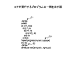
図3は、コア10乃至13が実行するプログラムの一例を示す図である。この例では、コア10乃至13の各々が、図3に示される同一の内容のプログラムを実行する。このプログラムをコア10乃至13のそれぞれが実行することにより、コア10乃至13がそれぞれの配列bの値の和aを求め、最後のコマンド"allreduce-sum"により、各コアが求めた和aの総和を求める。プログラム中の命令51は、最初のバリア同期命令である。バリア同期命令51の位置は、図2に対応させると、バリア同期位置41に相当する。プログラム中の命令52は、2番目のバリア同期命令である。バリア同期命令52の位置は、図2に対応させると、バリア同期位置42に相当する。命令53は、進捗管理ユニット14に対して、プログラム実行箇所が所定位置に到達したことを報告する進捗状況報告命令である。進捗状況報告命令53の位置は、図2に対応させると、プログラム中の所定位置43に相当する。
FIG. 3 is a diagram illustrating an example of a program executed by the
進捗状況報告命令53のパラメータmyrankは、当該プログラムを実行するコアの番号を示す。例えばコア10が実行するプログラムにおいて、パラメータmyrankは0に設定される。例えばコア11が実行するプログラムにおいて、パラメータmyrankは1に設定される。例えばコア12が実行するプログラムにおいて、パラメータmyrankは2に設定される。例えばコア13が実行するプログラムにおいて、パラメータmyrankは3に設定される。またパラメータngroupeは、当該プログラムを実行するコアが所属するグループを規定する。例えば、コア10乃至13を、コア10及びコア11が所属する第1のグループと、コア12及びコア13が所属する第2のグループとに分け、それぞれのグループにおいて独立に進捗のばらつきを調整してよい。即ち、第1のグループでは、コア10とコア11とのうち早い方のコアの進行速度を遅くするように優先度を調整し、第2のグループでは、コア12とコア13とのうち早い方のコアの進行速度を遅くするように優先度を調整してよい。また或いは、コア10乃至13の全てが同一のグループに属するようにパラメータngroupeを設定し、コア10乃至13間での相対的な進捗度合いに応じて、各コアの優先度を調整してよい。
The parameter myrank of the
あるコアにより進捗状況報告命令53が実行されると、パラメータmyrankとパラメータngroupeとが、当該コアから進捗管理部28に通知される。進捗管理部28は、この通知に応答して、パラメータmyrankが示す進捗管理レジスタのレジスタ値を変化させる(例えば1増加させる)。このようにして、複数のコア10乃至13の各々は、プログラム中の所定位置に挿入された所定のコマンドを実行すると、進捗管理レジスタ20乃至23のうちの対応するレジスタのレジスタ値を変化させる。進捗管理部28は、進捗管理レジスタ20乃至23のレジスタ値に基づいてコア10乃至13の優先度を変化させる際に、パラメータngroupeが示すグループ分けに応じて優先度を変化させてよい。
When the
図4は、図1の演算処理装置の動作の一例を示すフローチャートである。ステップS1において、あるコアのプログラム実行箇所が管理ポイント(即ちプログラム中の所定位置)に到達する。これにより、管理ポイントに到達した旨の報告が当該コアから進捗管理部28に送信される。
FIG. 4 is a flowchart showing an example of the operation of the arithmetic processing apparatus of FIG. In step S1, a program execution location of a certain core reaches a management point (that is, a predetermined position in the program). As a result, a report indicating that the management point has been reached is transmitted from the core to the
ステップS2において、進捗管理部28が、進捗管理レジスタ20乃至23を参照してレジスタ値をチェックする。ステップS3において、進捗管理部28は、今回管理ポイントに到達したコア以外のコアが対応する管理ポイントに既に到達しているか否かを判定する。即ち、今回管理ポイントに到達したコアが最も進捗の遅いコアであるか否かを判定する。今回管理ポイントに到達したコア以外のコアが対応する管理ポイントに既に到達していない場合、即ち、今回管理ポイントに到達したコアが最も進捗の遅いコアでない場合、ステップS4で、当該コアの進捗管理レジスタを1増加させる。それに続きステップS5で、進捗管理部28は、当該コアの共有リソース15へのアクセスの優先度を低下させるように、共有リソース15へ必要な通知(例えば各コアの優先度を示す優先度情報の送信)を行う。
In step S2, the
図5は、最速のコアが最初の管理ポイントに到達した状態の一例を示す図である。図6は、2番目に早いコアが最初の管理ポイントに到達した状態の一例を示す図である。図7は、最も遅いコアが最初の管理ポイントに到達した状態の一例を示す図である。これらの例において、バリア同期位置41及びバリア同期位置42は、図2で説明したものと同様である。この例では、3つのプログラム中の所定位置として、3つの管理ポイント61乃至63が設定されている。コア13が第1の管理ポイント61に最初に到達し、コア11が第1の管理ポイント61に2番目に到達し、コア12が第1の管理ポイント61に最も遅く到達している。
FIG. 5 is a diagram illustrating an example of a state in which the fastest core has reached the first management point. FIG. 6 is a diagram illustrating an example of a state in which the second earliest core has reached the first management point. FIG. 7 is a diagram illustrating an example of a state in which the slowest core has reached the first management point. In these examples, the barrier synchronization position 41 and the barrier synchronization position 42 are the same as those described in FIG. In this example, three management points 61 to 63 are set as predetermined positions in the three programs. The
図5に示す例の場合、第1の管理ポイント61に到達したコア13は最も進捗の遅いコアではないので、ステップS4で当該コア13の進捗管理レジスタ23が1増加される。それに続きステップS5で、当該コア13の共有リソース15へのアクセスの優先度を低下させるように、共有リソース15へ必要な通知が行われる。図6に示す例の場合も、第1の管理ポイント61に到達したコア11は最も進捗の遅いコアではないので、当該コア11の進捗管理レジスタ21が1増加され、当該コア11の共有リソース15へのアクセスの優先度が低下される。
In the example shown in FIG. 5, since the core 13 that has reached the first management point 61 is not the slowest progressing core, the
図4を再び参照し、ステップS3において、今回管理ポイントに到達したコア以外のコアが対応する管理ポイントに既に到達している場合、即ち、今回管理ポイントに到達したコアが最も進捗の遅いコアである場合、ステップS6に進む。ステップS6において、当該コア以外のコアの進捗管理レジスタを1減少させる。前述のように、あるコアのプログラム実行箇所がプログラム中の所定位置に到達すると、当該コアが最も遅いコアでない場合には、複数のレジスタのうちの当該コアに対応するレジスタのレジスタ値を所定値(この例では1)増加させる。但しステップS3に示すように、当該コアが最も遅いコアである場合には、複数のレジスタのうちの当該コア以外のコアに対応するレジスタのレジスタ値を所定値(この例では1)減少させてよい。 Referring to FIG. 4 again, in step S3, when a core other than the core that has reached the current management point has already reached the corresponding management point, that is, the core that has reached the current management point is the slowest progressing core. If there is, the process proceeds to step S6. In step S6, the progress management registers of cores other than the core are decremented by one. As described above, when the program execution location of a certain core reaches a predetermined position in the program, if the core is not the slowest core, the register value of the register corresponding to the core among the plurality of registers is set to the predetermined value. (In this example, 1) Increase. However, as shown in step S3, when the core is the slowest core, the register value of a register corresponding to a core other than the core among the plurality of registers is decreased by a predetermined value (1 in this example). Good.
なおこのステップにおける1減少させる処理は必ずしも必要ではないが、この処理によりある管理ポイントに全コアが到達した場合に進捗管理レジスタのレジスタ値を1減少させることで、最も遅いコアのレジスタ値を常に0の状態に保つことができる。従って、レジスタ間でのレジスタ値の比較をする必要なく、ある進捗管理レジスタのレジスタ値のみに基づいて、当該レジスタに対応するコアが相対的にどれだけ進捗しているのかを判断することができる。またこのようにすることで、今回管理ポイントに到達したコア以外のコアが対応する管理ポイントに既に到達しているか否かを判断するためには、他のコアの進捗管理レジスタの値が全て1以上であるか否かを判断すればよい。 Note that the process of decrementing by 1 in this step is not necessarily required, but when all the cores have reached a certain management point by this process, the register value of the slowest core is always set to 1 by decrementing the register value of the progress management register. It can be kept at zero. Therefore, it is possible to determine the relative progress of the core corresponding to the register based on only the register value of a certain progress management register without the need to compare the register values between the registers. . In addition, in this way, in order to determine whether or not a core other than the core that has reached the management point has already reached the corresponding management point, the values of the progress management registers of the other cores are all 1 What is necessary is just to judge whether it is above.
図7の例の場合、第1の管理ポイント61に到達したコア12は最も進捗の遅いコアであるので、ステップS6において、当該コア以外のコア10,11,13の進捗管理レジスタ20,21,23を1減少させる。これにより、最も進捗の遅いコア12に対応する進捗管理レジスタ22のレジスタ値は0のままとなる。
In the case of the example of FIG. 7, the core 12 that has reached the first management point 61 is the slowest progressing core. Therefore, in step S6, the progress management registers 20, 21, Decrease 23 by 1. As a result, the register value of the
図4を再び参照し、ステップS7において、進捗管理部28は、全てのコアの進捗管理レジスタの値が0であるか否かを判定する。全てのコアの進捗管理レジスタの値が0である場合、ステップS8において、共有リソース15に対する全コアのアクセス優先度をリセットして、初期状態のアクセス優先度に戻す。即ち、最も遅いコアがある管理ポイントに到達した時点で、何れのコアもその次の管理ポイントには未だ到達していない場合、コア間の進捗状況の差は十分に小さいとの判断に基づいて、初期状態のアクセス優先度に戻す。アクセス優先度の初期状態は、例えば、全てのコアに対して同一の優先度が設定されている状態、或いは優先度の設定無しの状態等であってよい。
Referring to FIG. 4 again, in step S7, the
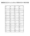
図8は、進捗管理レジスタのレジスタ値が変化する様子の一例を示す図である。最初に、コア13が管理ポイントに到達し、コア13に対応する進捗管理レジスタが0から1になる。次に、コア12が管理ポイントに到達し、コア12に対応する進捗管理レジスタが0から1になる。次に、コア11が管理ポイントに到達し、コア11に対応する進捗管理レジスタが0から1になる。次に、コア10が管理ポイントに到達すると、他の全てのコアが対応管理ポイントに到達しているので、コア11乃至13に対応する進捗管理レジスタが1減少して1から0になる。即ち、コア10乃至13に対応する進捗管理レジスタの値は全て0になる。
FIG. 8 is a diagram illustrating an example of how the register value of the progress management register changes. First, the
その後、コア12、コア11、コア12、コア10がこの順番で管理ポイントに到達することにより、コア10乃至13に対応する進捗管理レジスタの値は1,1,2,0となる。この時点で、コア13が管理ポイントに到達すると、他の全てのコアが対応管理ポイントに到達しているので、コア10乃至12に対応する進捗管理レジスタがそれぞれ1減少する。この結果、コア10乃至13に対応する進捗管理レジスタの値は0,0,1,0となる。
Thereafter, when the
以上のように変化する進捗管理レジスタ20乃至23のレジスタ値に基づいて、図1を参照して述べたように、進捗管理部28が、共有リソース15に対して優先度調整のための通知(例えば各コアの優先度を示す優先度情報の通知)を行う。この通知に基づいて、共有リソース15のリソース制御部が、共有リソースの割り当てを調整する。ここで共有リソース15のリソース制御部とは、例えば共有キャッシュ30のキャッシュ制御部、共有バス調停ユニット31、電源&クロック制御ユニット32等であってよい。
Based on the register values of the progress management registers 20 to 23 changing as described above, as described with reference to FIG. 1, the
まず、電源&クロック制御ユニット32による共有リソースの割り当てについて説明する。一般に、コアの消費電力と周波数とには密接な関係がある。コアの動作周波数を上げて処理速度を増加させるためには、電源電圧を上げることが好ましく、その結果、コアの消費電力は大きくなる。その際、放熱の問題、環境の問題、更にはコスト等の観点から、プロセッサが用いる電力に上限を設定することがある。このように使用電力に上限の設定がある場合、周波数や電力も各コアの共有資源と考えることができる。限られた電力の分配をコアの優先度に応じて調整することによって、進捗の遅いコアの周波数を相対的に高くし、進捗の早いコアの周波数を相対的に遅くすることが考えられる。 First, allocation of shared resources by the power supply & clock control unit 32 will be described. In general, there is a close relationship between power consumption and frequency of the core. In order to increase the processing frequency by increasing the operating frequency of the core, it is preferable to increase the power supply voltage. As a result, the power consumption of the core increases. At this time, an upper limit may be set for the power used by the processor from the viewpoint of heat dissipation, environmental problems, and cost. Thus, when there is an upper limit setting for power consumption, frequency and power can also be considered as shared resources of each core. It is conceivable to adjust the limited power distribution according to the priority of the core to relatively increase the frequency of the slow progressing core and relatively slow the frequency of the fast progressing core.
即ち、図1に示されるように、電源&クロック制御ユニット32は、進捗管理部28から各コアの優先度を示す優先度情報を受け取る。電源&クロック制御ユニット32は、優先度情報に基づいて、コア10乃至13に供給する電源電圧及びクロック周波数を変化させる。この際、進捗管理部28から、電源&クロック制御ユニット32に対して、電源電圧及びクロック周波数の変化を要求するようにしてもよい。電源&クロック制御ユニット32は、進捗が早いために優先度が低いコアに対しては、供給する電源電圧及びクロック周波数を低下させてよい。また同様に、電源&クロック制御ユニット32は、進捗が遅いために優先度が高いコアに対して、供給する電源電圧及びクロック周波数を増加させてもよい。
That is, as shown in FIG. 1, the power supply & clock control unit 32 receives priority information indicating the priority of each core from the
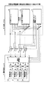
図9は、共有バス調停ユニット31における共有リソースの割り当て機構の一例を示す図である。図9には、コア10乃至13、進捗管理ユニット14、優先化装置71、LRUユニット72、AND回路73乃至76、OR回路77、及び2次キャッシュ78が示される。図1の共有バス調停ユニット31は、優先化装置71及びLRUユニット72を含んでよく、AND回路73乃至76、OR回路77、及び2次キャッシュ78は、図1の共有キャッシュ30に含まれてよい。なお優先化装置71は、共有バス調停ユニット31側ではなく進捗管理ユニット14側に含まれてもよい。
FIG. 9 is a diagram illustrating an example of a shared resource allocation mechanism in the shared bus arbitration unit 31. FIG. 9 shows the
1次キャッシュはコア10乃至13の各々に内蔵されており、2次キャッシュ78は、メモリ階層において、外部メモリ装置と1次キャッシュとの間に存在する。1次キャッシュへのアクセスにおいてキャッシュミスが発生した場合、2次キャッシュ78へのアクセスが実行される。LRUユニット72は、複数のコア10乃至13のうちで最後に2次キャッシュ78にアクセスしてから最も時間の経過しているLRU(Least Recently Used)コアが何れのコアであるのかを示す情報を保持している。LRUユニット72は、コア10乃至13に対して特に優先度の設定が無い場合、他のコアに優先してLRUコアに2次キャッシュ78へのバス(OR回路77の出力が接続される部分)へのアクセスを許可する。具体的には、例えばコア11がLRUコアである場合、コア11がアクセス先のアドレスを出力し且つアクセス許可を要求するアクセスリクエスト信号をアサートすると、LRUユニット72は、対応するAND回路74への信号を1に設定してアクセスを許可する。即ち、アクセス許可されたコア11の出力するアドレス信号が、AND回路74及びOR回路77を介して2次キャッシュ78に供給される。コア11がアクセスリクエスト信号をアサートしている状態で、他のコアが2次キャッシュ78にアクセスしようとしても、LRUコアであるコア11が優先されるので、他のコアは2次キャッシュ78にアクセスすることはできない。即ち、LRUコアであるコア11以外のコア10,12,13からアクセスリクエスト信号を受け取っても、LRUユニット72は、それぞれ対応するAND回路73,75,76への信号を0のまま保持する。
The primary cache is built in each of the
進捗管理ユニット14によりコア10乃至13に対して優先度設定がされている場合、優先化装置71により、LRUユニット72によるアクセス許可動作を調整する。具体的には、優先化装置71は、コア10乃至13の優先度に関する優先度情報を進捗管理ユニット14から受け取り、当該優先度情報に基づいて、優先度の相対的に低いコアに対しては、LRUユニット72へのアクセスリクエスト信号を遮断する。即ち、コア10乃至13からのアクセスリクエスト信号は、通常は優先化装置71を介してLRUユニット72に供給されるが、優先度の相対的に低いコアからのアクセスリクエスト信号は、優先化装置71により遮断され、LRUユニット72に供給されない。
When the priority is set for the
図10は、優先化装置71の構成の一例を示す図である。優先化装置71は、AND回路80−1乃至80−4、OR回路81−1乃至81−4、2入力のうち一方が負論理入力であるAND回路82−1乃至82−4及び83−1乃至83−4、AND回路84−1乃至84−4、及びOR回路85−1乃至85−4を含む。進捗管理ユニット14は、進捗管理レジスタのレジスタ値が0である場合に1となり且つ当該レジスタ値が0以外の時に0となる優先度情報を、AND回路80−1乃至80−4の第1の入力に印加する。この優先度情報は更に、AND回路83−1乃至83−4及びAND回路84−1乃至84−4の第1の入力にも印加される。例えばコア10に対して優先度情報が0の場合、このコア10の進捗管理レジスタ20の値は1以上であり、コア10が相対的に進捗していること、即ちコア10の優先度は低いことを示す。また例えばコア10に対して優先度情報が1の場合、このコア10の進捗管理レジスタ20の値は0であり、コア10が相対的に遅れていること、即ちコア10の優先度は高いことを示す。
FIG. 10 is a diagram illustrating an example of the configuration of the prioritizing device 71. The prioritizing device 71 includes AND circuits 80-1 to 80-4, OR circuits 81-1 to 81-4, AND circuits 82-1 to 82-4 and 83-1, one of which is a negative logic input. Through 83-4, AND circuits 84-1 through 84-4, and OR circuits 85-1 through 85-4. The
コア10乃至13は、アクセス要求時にアクセスリクエスト信号を1にアサートし、これらアクセスリクエスト信号はAND回路80−1乃至80−4の第2の入力に印加される。またこれらアクセスリクエスト信号は、AND回路82−1乃至82−4の第1の入力、及びAND回路84−1乃至84−4の第2の入力に印加される。AND回路82−1乃至82−4の出力が、AND回路83−1乃至83−4の第2の入力に印加される。またAND回路82−1乃至82−4の第2の入力には、OR回路81−1乃至81−4の出力が印加される。
The
例えばコア10に対する優先度情報が印加されるAND回路83−4及び84−4に着目した場合、コア10の優先度情報が1である(即ち優先度が高い)場合、コア10からのアクセスリクエスト信号はAND回路84−4側の経路を通る。即ち、コア10の優先度情報が1である(即ち優先度が高い)場合、コア10からのアクセスリクエスト信号は、AND回路84−4を通過し、OR回路85−4を介して優先化装置71から出力される。出力された信号は、優先化装置71からLRUユニット72に供給される。
For example, when attention is paid to AND circuits 83-4 and 84-4 to which priority information for the
またコア10の優先度情報が0である(即ち優先度が低い)場合、コア10からのアクセスリクエスト信号はAND回路83−4側の経路を通る。但し、AND回路80−2乃至80−4及びOR回路81−4による論理演算に相当する所定の条件が満たされた場合のみ、アクセスリクエスト信号は、AND回路82−4及びAND回路83−4を通過し、OR回路85−4を介して優先化装置71から出力される。出力された信号は、優先化装置71からLRUユニット72に供給される。
When the priority information of the
AND回路80−1乃至80−4はそれぞれ、対応するコア10乃至13がアクセスリクエスト信号をアサートし且つ対応優先度が高いときにのみ、その出力を1にする。OR回路81−4は、AND回路80−2乃至80−4の出力のOR演算を行い、OR演算結果を出力する。従って、OR回路81−4の出力が1になるのは、コア10以外の少なくとも1つのコアで優先度の高いものがアクセスリクエスト信号をアサートした場合である。それ以外の場合、OR回路81−4の出力は0になる。
The AND circuits 80-1 to 80-4 set their outputs to 1 only when the corresponding
従ってコア10の優先度が低い場合、コア10以外の少なくとも1つのコアで優先度の高いものがアクセスリクエスト信号をアサートすれば、コア10のアクセスリクエスト信号はLRUユニット72に供給されない。コア10の優先度が低い場合、コア10のアクセスリクエスト信号がLRUユニット72に供給されるのは、コア10以外のコアで優先度の高いものがアクセスリクエスト信号をアサートしていないときのみである。
Therefore, when the priority of the
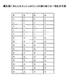
図11乃至図14は、優先度に応じたキャッシュのウェイの割り当ての一例を示す図である。共有キャッシュ30は、進捗管理部28からの優先度情報に基づいて、ウェィの割り当てを制御してよい。複数のコア10乃至13は、それぞれが保有する専用の1次キャッシュとは別に、2次キャッシュである共有キャッシュ30にアクセスできる。この際、共有キャッシュ30の共有リソースであるウェイの使用においては、コア10乃至13間での競合に起因してキャッシュミスが発生する場合がある。競合によるキャッシュミスはCPU内のコア数が増えると増加する傾向にある。そこで、コア間の競合によるキャッシュミスの頻度を下げるために、コアに対して動的なキャッシュのウェイ分割をすることが考えられる。その際、ウェイ分割の仕方をコアの優先度に基づいて調整することで、進捗の遅いコアに対しては優先的にウェイを割り当てることが考えられる。
FIG. 11 to FIG. 14 are diagrams illustrating an example of cache way allocation according to priority. The shared
図1に示す進捗管理ユニット14からの優先度情報に基づいて、共有キャッシュ30がキャッシュのウェイ分割を行う例について以下に説明する。以下の説明において、ウェイの数(即ち各インデックスに対応するタグの数)は16であるとする。
An example in which the shared
図11乃至図14の例では、縦16行が16のウェイを示し、横4列がそれぞれ4つのインデックスに対応する。コア10乃至13の進捗状況が同一である場合、図11に示すように、各コアには4つずつウェイを占有させてよい。なお"0"はコア10に占有させるウェイ、"1"はコア11に占有させるウェイ、"2"はコア12に占有させるウェイ、"3"はコア13に占有させるウェイを示す。
In the examples of FIGS. 11 to 14, 16 rows in the vertical direction indicate 16 ways, and 4 columns in the horizontal direction respectively correspond to 4 indexes. When the progress of the
例えばコア10が進んでおり他のコア11乃至13が遅れている場合、共有キャッシュ30における動的なキャッシュのウェイ割り当てにより、コア10が1つのウェイを占有し、他のコア11乃至13が5つずつウェイを占有するようにしてよい。図12に、そのようにウェイを割り当てた例が示される。
For example, when the
また例えばコア10及び11が進んでおり他のコア12及び13が遅れている場合、共有キャッシュ30における動的なキャッシュのウェイ割り当てにより、コア10及び11がそれぞれ2つのウェイを占有し、他のコア12及び13が6つずつウェイを占有するようにしてよい。図13に、そのようにウェイを割り当てた例が示される。
Further, for example, when the
また例えばコア10乃至12が進んでおり他のコア13が遅れている場合、共有キャッシュ30における動的なキャッシュのウェイ割り当てにより、コア10乃至12がそれぞれ3つのウェイを占有し、他のコア13が7つのウェイを占有するようにしてよい。図14に、そのようにウェイを割り当てた例が示される。
Further, for example, when the
上記のウェイの割り当て例はあくまで一例であり、限定を意図するものではない。上記以外の様々なウェイの割り当てが可能である。 The above way allocation examples are merely examples, and are not intended to be limiting. Various ways other than the above can be assigned.
以上、演算処理装置を実施例に基づいて説明したが、本発明は上記実施例に限定されるものではなく、特許請求の範囲に記載の範囲内で様々な変形が可能である。 The arithmetic processing apparatus has been described based on the embodiments. However, the present invention is not limited to the above embodiments, and various modifications can be made within the scope of the claims.
例えば、進捗管理レジスタ20乃至23のレジスタ値の書き換えや優先度の調整は進捗管理部28により集中管理的に実行される例について説明したが、そのように集中管理的にではなく各コア10乃至13により分散的に実行されてもよい。例えば、各コア10乃至13が、所定の命令を実行することにより、対応する進捗管理レジスタ20乃至23のレジスタ値を直接に書き換えてよい。また各コア10乃至13が、進捗管理レジスタ20乃至23のレジスタ値を参照して、自らの優先度を下げるように、各共有リソースの制御部に働きかけてもよい。
For example, the example in which the rewriting of the register values of the progress management registers 20 to 23 and the adjustment of the priority are executed in a centralized manner by the
また同期ポイントは、バリア同期によるものでなくとも、任意の方式で同期を確立するものであってよい。また同期ポイント間の進捗管理ポイント(進捗をチェックする所定位置)の数は、1つであっても複数であってもよい。また同期ポイントが設けられることなく、プログラム動作開始から終了までの間に1つ又は複数の管理ポイントが設けられていてもよい。 Further, the synchronization point may be one that establishes synchronization by an arbitrary method, not by barrier synchronization. The number of progress management points (predetermined positions for checking progress) between the synchronization points may be one or plural. Further, one or a plurality of management points may be provided between the start and end of the program operation without providing a synchronization point.
10,11,12,13 コア
14 進捗管理ユニット
15 共有リソース
20,21,22,23 進捗管理レジスタ
24,25,26,27 加減算器
28 進捗管理部
30 共有キャッシュ
31 共有バス調停ユニット
32 電源&クロック制御ユニット
10, 11, 12, 13
Claims (6)
前記複数の演算処理部のそれぞれに対応して設けられた複数のレジスタと、
を含み、前記複数の演算処理部の各々について、演算処理部がプログラム中の特定の命令を実行すると前記複数のレジスタのうちの対応するレジスタのレジスタ値が変化され、前記特定の命令が実行される度に前記複数のレジスタのレジスタ値に応じて前記複数の演算処理部の優先度が変化され、
前記複数の演算処理部のいずれかが前記特定の命令を実行する度に、前記複数のレジスタのレジスタ値に基づいて進捗状況を判断し、前記複数の演算処理部のうちの相対的に早い演算処理部の優先度を相対的に低下させる
ことを特徴とする演算処理装置。 A plurality of arithmetic processing units for performing arithmetic processing;
A plurality of registers provided corresponding to each of the plurality of arithmetic processing units;
For each of the plurality of arithmetic processing units, when the arithmetic processing unit executes a specific instruction in the program, the register value of the corresponding register among the plurality of registers is changed, and the specific instruction is executed. Each time the priority of the plurality of arithmetic processing units is changed according to the register values of the plurality of registers ,
Each time any one of the plurality of arithmetic processing units executes the specific instruction, the progress status is determined based on the register values of the plurality of registers, and the relatively fast calculation of the plurality of arithmetic processing units is performed. An arithmetic processing device characterized by relatively lowering the priority of a processing unit.
前記複数の演算処理部のそれぞれに対応して設けられた複数のレジスタと、
を含み、前記複数の演算処理部の各々について、演算処理部がプログラム中の特定の命令を実行すると前記複数のレジスタのうちの対応するレジスタのレジスタ値が変化され、前記特定の命令が実行される度に前記複数のレジスタのレジスタ値に応じて前記複数の演算処理部の優先度が変化され、
前記複数の演算処理部のうちの一の演算処理部がプログラム中の特定の命令を実行すると、前記一の演算処理部が最も遅い演算処理部でない場合に前記複数のレジスタのうちの前記一の演算処理部に対応するレジスタのレジスタ値を所定値増加させ、前記一の演算処理部が最も遅い演算処理部である場合に前記複数のレジスタのうちの前記一の演算処理部以外の演算処理部に対応するレジスタのレジスタ値を前記所定値減少させることを特徴とする演算処理装置。 A plurality of arithmetic processing units for performing arithmetic processing;
A plurality of registers provided corresponding to each of the plurality of arithmetic processing units;
For each of the plurality of arithmetic processing units, when the arithmetic processing unit executes a specific instruction in the program, the register value of the corresponding register among the plurality of registers is changed, and the specific instruction is executed. Each time the priority of the plurality of arithmetic processing units is changed according to the register values of the plurality of registers,
When one arithmetic processing unit of the plurality of arithmetic processing units executes a specific instruction in the program, the one of the plurality of registers when the one arithmetic processing unit is not the slowest arithmetic processing unit. An arithmetic processing unit other than the first arithmetic processing unit among the plurality of registers when the register value of the register corresponding to the arithmetic processing unit is increased by a predetermined value and the one arithmetic processing unit is the slowest arithmetic processing unit arithmetic processor you wherein the register value of the corresponding register to reduce the predetermined value.
前記複数の演算処理部の各々について、演算処理部がプログラム中の特定の命令を実行すると、前記複数の演算処理部のそれぞれに対応して設けられた複数のレジスタのうちの対応するレジスタのレジスタ値を変化させ、
前記特定の命令が実行される度に前記複数のレジスタのレジスタ値に応じて前記複数の演算処理部の優先度を変化させ、
前記複数の演算処理部のいずれかが前記特定の命令を実行する度に、前記複数のレジスタのレジスタ値に基づいて進捗状況を判断し、前記複数の演算処理部のうちの相対的に早い演算処理部の優先度を相対的に低下させる
各段階を含む演算処理方法。
Perform arithmetic processing by multiple arithmetic processing units,
For each of the plurality of arithmetic processing units, when the arithmetic processing unit executes a specific instruction in the program, a register of a corresponding register among a plurality of registers provided corresponding to each of the plurality of arithmetic processing units Change the value,
Each time the specific instruction is executed, the priority of the plurality of arithmetic processing units is changed according to register values of the plurality of registers ,
Each time any one of the plurality of arithmetic processing units executes the specific instruction, the progress status is determined based on the register values of the plurality of registers, and the relatively fast calculation of the plurality of arithmetic processing units is performed. An arithmetic processing method including each step of relatively lowering the priority of the processing unit .
Priority Applications (2)
| Application Number | Priority Date | Filing Date | Title |
|---|---|---|---|
| JP2012160696A JP6074932B2 (en) | 2012-07-19 | 2012-07-19 | Arithmetic processing device and arithmetic processing method |
| US13/907,971 US20140025925A1 (en) | 2012-07-19 | 2013-06-03 | Processor and control method thereof |
Applications Claiming Priority (1)
| Application Number | Priority Date | Filing Date | Title |
|---|---|---|---|
| JP2012160696A JP6074932B2 (en) | 2012-07-19 | 2012-07-19 | Arithmetic processing device and arithmetic processing method |
Publications (2)
| Publication Number | Publication Date |
|---|---|
| JP2014021774A JP2014021774A (en) | 2014-02-03 |
| JP6074932B2 true JP6074932B2 (en) | 2017-02-08 |
Family
ID=49947570
Family Applications (1)
| Application Number | Title | Priority Date | Filing Date |
|---|---|---|---|
| JP2012160696A Active JP6074932B2 (en) | 2012-07-19 | 2012-07-19 | Arithmetic processing device and arithmetic processing method |
Country Status (2)
| Country | Link |
|---|---|
| US (1) | US20140025925A1 (en) |
| JP (1) | JP6074932B2 (en) |
Families Citing this family (2)
| Publication number | Priority date | Publication date | Assignee | Title |
|---|---|---|---|---|
| US11204871B2 (en) * | 2015-06-30 | 2021-12-21 | Advanced Micro Devices, Inc. | System performance management using prioritized compute units |
| US11567556B2 (en) * | 2019-03-28 | 2023-01-31 | Intel Corporation | Platform slicing of central processing unit (CPU) resources |
Family Cites Families (23)
| Publication number | Priority date | Publication date | Assignee | Title |
|---|---|---|---|---|
| JPH0640324B2 (en) * | 1989-10-26 | 1994-05-25 | インターナショナル・ビジネス・マシーンズ・コーポレーション | Multiprocessor system and process synchronization method thereof |
| US5365228A (en) * | 1991-03-29 | 1994-11-15 | International Business Machines Corporation | SYNC-NET- a barrier synchronization apparatus for multi-stage networks |
| US5649102A (en) * | 1993-11-26 | 1997-07-15 | Hitachi, Ltd. | Distributed shared data management system for controlling structured shared data and for serializing access to shared data |
| JPH07248967A (en) * | 1994-03-11 | 1995-09-26 | Hitachi Ltd | Memory control system |
| JPH07271614A (en) * | 1994-04-01 | 1995-10-20 | Hitachi Ltd | Priority control system for task restricted in execution time |
| US5682480A (en) * | 1994-08-15 | 1997-10-28 | Hitachi, Ltd. | Parallel computer system for performing barrier synchronization by transferring the synchronization packet through a path which bypasses the packet buffer in response to an interrupt |
| JP3532037B2 (en) * | 1996-07-31 | 2004-05-31 | 富士通株式会社 | Parallel computer |
| JP3636871B2 (en) * | 1997-09-16 | 2005-04-06 | 株式会社日立製作所 | Parallel processor system |
| US6216174B1 (en) * | 1998-09-29 | 2001-04-10 | Silicon Graphics, Inc. | System and method for fast barrier synchronization |
| US6763519B1 (en) * | 1999-05-05 | 2004-07-13 | Sychron Inc. | Multiprogrammed multiprocessor system with lobally controlled communication and signature controlled scheduling |
| JP2004038767A (en) * | 2002-07-05 | 2004-02-05 | Matsushita Electric Ind Co Ltd | Bus arbitration device |
| TWI256553B (en) * | 2004-12-17 | 2006-06-11 | Ind Tech Res Inst | Apparatus and method for hardware semaphore |
| US8645959B2 (en) * | 2005-03-30 | 2014-02-04 | Intel Corporaiton | Method and apparatus for communication between two or more processing elements |
| JP2009025939A (en) * | 2007-07-18 | 2009-02-05 | Renesas Technology Corp | Task control method and semiconductor integrated circuit |
| JP2009176116A (en) * | 2008-01-25 | 2009-08-06 | Univ Waseda | Multiprocessor system and method for synchronizing multiprocessor system |
| JP5181762B2 (en) * | 2008-03-25 | 2013-04-10 | 富士通株式会社 | Arithmetic apparatus and server for executing distributed processing, and distributed processing method |
| US8365177B2 (en) * | 2009-01-20 | 2013-01-29 | Oracle International Corporation | Dynamically monitoring and rebalancing resource allocation of monitored processes based on execution rates of measuring processes at multiple priority levels |
| EP2396730A4 (en) * | 2009-02-13 | 2013-01-09 | Alexey Raevsky | Devices and methods for optimizing data-parallel processing in multi-core computing systems |
| US8335911B2 (en) * | 2009-05-21 | 2012-12-18 | Oracle America, Inc. | Dynamic allocation of resources in a threaded, heterogeneous processor |
| JP5549575B2 (en) * | 2010-12-17 | 2014-07-16 | 富士通株式会社 | Parallel computer system, synchronization device, and control method for parallel computer system |
| US20120179896A1 (en) * | 2011-01-10 | 2012-07-12 | International Business Machines Corporation | Method and apparatus for a hierarchical synchronization barrier in a multi-node system |
| US8843932B2 (en) * | 2011-01-12 | 2014-09-23 | Wisconsin Alumni Research Foundation | System and method for controlling excessive parallelism in multiprocessor systems |
| US8990823B2 (en) * | 2011-03-10 | 2015-03-24 | International Business Machines Corporation | Optimizing virtual machine synchronization for application software |
-
2012
- 2012-07-19 JP JP2012160696A patent/JP6074932B2/en active Active
-
2013
- 2013-06-03 US US13/907,971 patent/US20140025925A1/en not_active Abandoned
Also Published As
| Publication number | Publication date |
|---|---|
| JP2014021774A (en) | 2014-02-03 |
| US20140025925A1 (en) | 2014-01-23 |
Similar Documents
| Publication | Publication Date | Title |
|---|---|---|
| US8676976B2 (en) | Microprocessor with software control over allocation of shared resources among multiple virtual servers | |
| EP3092567B1 (en) | System and method for isolating i/o execution via compiler and os support | |
| US20150205644A1 (en) | Task Scheduler Mechanism, Operating System, and Multiprocessor System | |
| JP2010079908A (en) | Memory management apparatus and its method | |
| JP6161301B2 (en) | Interrupt spread method, interrupt request signal spreader circuit, and system-on-chip including the same | |
| JP5633564B2 (en) | Multi-core system and external I / O bus control method | |
| Kao et al. | Data-locality-aware mapreduce real-time scheduling framework | |
| WO2016202153A1 (en) | Gpu resource allocation method and system | |
| JP6074932B2 (en) | Arithmetic processing device and arithmetic processing method | |
| Chiang et al. | Kernel mechanisms with dynamic task-aware scheduling to reduce resource contention in NUMA multi-core systems | |
| Rezaei et al. | Ultrashare: Fpga-based dynamic accelerator sharing and allocation | |
| US20050066093A1 (en) | Real-time processor system and control method | |
| Nair et al. | Mediator-a mixed criticality deadline honored arbiter for multi-core real-time systems | |
| JP4868012B2 (en) | Computer system, computer system control method, and program | |
| JP6079518B2 (en) | Arithmetic processing device and control method of arithmetic processing device | |
| JP2017016250A (en) | Barrier synchronization device, barrier synchronization method, and program | |
| JP2015041199A (en) | Information processing apparatus | |
| JP5734941B2 (en) | Multicore processor control program, electronic device, and control method | |
| JP2008250419A (en) | Competition arbitration apparatus, master-slave system, and method for competition arbitration | |
| US20220306135A1 (en) | Method for operating a processing unit | |
| US9389919B2 (en) | Managing workload distribution among computer systems based on intersection of throughput and latency models | |
| JP5768586B2 (en) | COMPUTER DEVICE, COMPUTER DEVICE CONTROL METHOD, AND PROGRAM | |
| JPWO2012066621A1 (en) | Information processing system | |
| WO2019188182A1 (en) | Pre-fetch controller | |
| Nadeem et al. | Bandwidth Stealing TDMA Arbitration for Real-Time Multiprocessor Applications |
Legal Events
| Date | Code | Title | Description |
|---|---|---|---|
| A621 | Written request for application examination |
Free format text: JAPANESE INTERMEDIATE CODE: A621 Effective date: 20150406 |
|
| A977 | Report on retrieval |
Free format text: JAPANESE INTERMEDIATE CODE: A971007 Effective date: 20151021 |
|
| A131 | Notification of reasons for refusal |
Free format text: JAPANESE INTERMEDIATE CODE: A131 Effective date: 20151104 |
|
| A521 | Request for written amendment filed |
Free format text: JAPANESE INTERMEDIATE CODE: A523 Effective date: 20151222 |
|
| A131 | Notification of reasons for refusal |
Free format text: JAPANESE INTERMEDIATE CODE: A131 Effective date: 20160517 |
|
| A521 | Request for written amendment filed |
Free format text: JAPANESE INTERMEDIATE CODE: A523 Effective date: 20160719 |
|
| TRDD | Decision of grant or rejection written | ||
| A01 | Written decision to grant a patent or to grant a registration (utility model) |
Free format text: JAPANESE INTERMEDIATE CODE: A01 Effective date: 20161213 |
|
| A61 | First payment of annual fees (during grant procedure) |
Free format text: JAPANESE INTERMEDIATE CODE: A61 Effective date: 20161226 |
|
| R150 | Certificate of patent or registration of utility model |
Ref document number: 6074932 Country of ref document: JP Free format text: JAPANESE INTERMEDIATE CODE: R150 |