JP6071077B2 - Method for manufacturing a spectral imaging detector - Google Patents
Method for manufacturing a spectral imaging detector Download PDFInfo
- Publication number
- JP6071077B2 JP6071077B2 JP2014500514A JP2014500514A JP6071077B2 JP 6071077 B2 JP6071077 B2 JP 6071077B2 JP 2014500514 A JP2014500514 A JP 2014500514A JP 2014500514 A JP2014500514 A JP 2014500514A JP 6071077 B2 JP6071077 B2 JP 6071077B2
- Authority
- JP
- Japan
- Prior art keywords
- photosensor
- substrate
- scintillator
- row
- scintillator array
- Prior art date
- Legal status (The legal status is an assumption and is not a legal conclusion. Google has not performed a legal analysis and makes no representation as to the accuracy of the status listed.)
- Active
Links
- 238000000034 method Methods 0.000 title claims description 32
- 238000000701 chemical imaging Methods 0.000 title description 6
- 238000004519 manufacturing process Methods 0.000 title 1
- 239000000758 substrate Substances 0.000 claims description 81
- 230000008878 coupling Effects 0.000 claims description 10
- 238000010168 coupling process Methods 0.000 claims description 10
- 238000005859 coupling reaction Methods 0.000 claims description 10
- 239000000463 material Substances 0.000 claims description 10
- 230000005855 radiation Effects 0.000 description 17
- 238000002591 computed tomography Methods 0.000 description 8
- 238000003384 imaging method Methods 0.000 description 8
- 230000003595 spectral effect Effects 0.000 description 5
- 230000000295 complement effect Effects 0.000 description 4
- 238000012986 modification Methods 0.000 description 3
- 230000004048 modification Effects 0.000 description 3
- 239000000853 adhesive Substances 0.000 description 2
- 230000001070 adhesive effect Effects 0.000 description 2
- 230000000712 assembly Effects 0.000 description 2
- 238000000429 assembly Methods 0.000 description 2
- 238000001514 detection method Methods 0.000 description 2
- 230000008859 change Effects 0.000 description 1
- 230000006870 function Effects 0.000 description 1
- 230000003287 optical effect Effects 0.000 description 1
- 238000005498 polishing Methods 0.000 description 1
- 230000008569 process Effects 0.000 description 1
- 230000004044 response Effects 0.000 description 1
- 238000000926 separation method Methods 0.000 description 1
- 229910052710 silicon Inorganic materials 0.000 description 1
- 239000010703 silicon Substances 0.000 description 1
- 238000001228 spectrum Methods 0.000 description 1
Images


Classifications
-
- G—PHYSICS
- G01—MEASURING; TESTING
- G01T—MEASUREMENT OF NUCLEAR OR X-RADIATION
- G01T1/00—Measuring X-radiation, gamma radiation, corpuscular radiation, or cosmic radiation
- G01T1/16—Measuring radiation intensity
- G01T1/20—Measuring radiation intensity with scintillation detectors
- G01T1/2006—Measuring radiation intensity with scintillation detectors using a combination of a scintillator and photodetector which measures the means radiation intensity
-
- G—PHYSICS
- G01—MEASURING; TESTING
- G01T—MEASUREMENT OF NUCLEAR OR X-RADIATION
- G01T1/00—Measuring X-radiation, gamma radiation, corpuscular radiation, or cosmic radiation
- G01T1/29—Measurement performed on radiation beams, e.g. position or section of the beam; Measurement of spatial distribution of radiation
- G01T1/2914—Measurement of spatial distribution of radiation
- G01T1/2985—In depth localisation, e.g. using positron emitters; Tomographic imaging (longitudinal and transverse section imaging; apparatus for radiation diagnosis sequentially in different planes, steroscopic radiation diagnosis)
-
- H—ELECTRICITY
- H01—ELECTRIC ELEMENTS
- H01L—SEMICONDUCTOR DEVICES NOT COVERED BY CLASS H10
- H01L31/00—Semiconductor devices sensitive to infrared radiation, light, electromagnetic radiation of shorter wavelength or corpuscular radiation and specially adapted either for the conversion of the energy of such radiation into electrical energy or for the control of electrical energy by such radiation; Processes or apparatus specially adapted for the manufacture or treatment thereof or of parts thereof; Details thereof
- H01L31/02—Details
- H01L31/0232—Optical elements or arrangements associated with the device
- H01L31/02322—Optical elements or arrangements associated with the device comprising luminescent members, e.g. fluorescent sheets upon the device
Landscapes
- General Physics & Mathematics (AREA)
- Physics & Mathematics (AREA)
- Spectroscopy & Molecular Physics (AREA)
- Life Sciences & Earth Sciences (AREA)
- High Energy & Nuclear Physics (AREA)
- Molecular Biology (AREA)
- Health & Medical Sciences (AREA)
- Condensed Matter Physics & Semiconductors (AREA)
- Electromagnetism (AREA)
- Engineering & Computer Science (AREA)
- Computer Hardware Design (AREA)
- Microelectronics & Electronic Packaging (AREA)
- Power Engineering (AREA)
- Measurement Of Radiation (AREA)
- Apparatus For Radiation Diagnosis (AREA)
Description
本発明は、概して、スペクトルイメージングに関し、より具体的には、スペクトルイメージング検出器に関し、コンピュータトモグラフィ(CT)に関連して記述される。しかしながら、本発明は、他のイメージングモダリティにも適応できる。 The present invention relates generally to spectral imaging, and more specifically to spectral imaging detectors and is described in the context of computer tomography (CT). However, the present invention can be applied to other imaging modalities.
通常のコンピュータトモグラフィ(CT)スキャナは、概して静止しているガントリに回転可能に取り付けられる回転ガントリを有する。回転ガントリは、X線管及び検出器アレイを支持し、検出器アレイは、検査領域を横切ってX線管と反対側の、回転可能なガントリ上に取り付けられる。回転ガントリ並びにX線管及び検出器アレイは、縦軸又はz軸を中心に検査領域の周りを回転する。X線管は、放射線を放出するように構成され、放射線は、検査領域(及び検査領域内の被検体又は対象の一部)を横切り、検出器アレイに投じられる。検出器アレイは、放射線を検出し、検査領域及びそこに配置される被検体又は対象を示す電気信号を生成する。再構成器は、投影データを再構成し、ボリュメトリック画像データを生成する。 A typical computer tomography (CT) scanner has a rotating gantry that is rotatably mounted to a generally stationary gantry. The rotating gantry supports the x-ray tube and detector array, and the detector array is mounted on a rotatable gantry across the examination region and opposite the x-ray tube. The rotating gantry and x-ray tube and detector array rotate around the examination region about the longitudinal axis or the z-axis. The x-ray tube is configured to emit radiation that is traversed across the examination region (and a portion of the subject or object within the examination region) and is directed to the detector array. The detector array detects radiation and generates an electrical signal indicating the examination region and the subject or object placed therein. The reconstructor reconstructs the projection data and generates volumetric image data.
スペクトルCTの場合、スキャナは、ダブルデッカー(2段)タイプの検出器アレイのようなエネルギー分解検出器アレイを有することができる。2段タイプの検出器アレイ100の例示の一部が、図1に示される。検出器100は、x方向106に、基板104に沿って互いに並べられる複数の検出器モジュール102を有する。各モジュール102は、フォトダイオード基板116の対応する第1及び第2の検出領域112及び114に光学的に結合される第1及び第2のシンチレータ行108及び110を有する。第1及び第2のシンチレータ行108及び110は、第1のシンチレータ行108が入射放射線120に対して第2のシンチレータ素子110より上にあるように、互いに対し配置される。概して、より低いエネルギーのX線フォトンは、上側のシンチレータ行108に吸収されやすく、より高いエネルギーのX線フォトンは、下側のシンチレータ行110に吸収されやすい。第1及び第2のシンチレータ行108及び110並びに検出領域112及び114は、z方向122に沿って延在し、検出器素子の複数の行を形成する。
In the case of spectral CT, the scanner can have an energy-resolved detector array, such as a double-decker type detector array. An example portion of a two-stage
図1の検出器アレイ100によって、x方向106の検出器アレイ100の解像度は、一般に、x方向106における各々のモジュール102のフォトダイオード基板116の有限の厚さ124によって制限され、かかる厚さは、100ミクロン〜400ミクロンのオーダーである。残念なことに、より薄いフォトダイオード基板は、壊れやすく、検出器アレイ100の検出器モジュール102のような検出器モジュールを構成するにはあまり適切でない。
With the
本発明の以下の見地は、上述した問題及びその他に対処する新しい及び/又は改善された技法を提供する。 The following aspects of the present invention provide new and / or improved techniques that address the above-mentioned problems and others.
1つの見地によれば、方法は、2つの対向する主面を有するフォトセンサ基板を得るステップを含む。2つの対向する主面の一方は、少なくとも1つのフォトセンサ素子の少なくとも1つのフォトセンサ行を含み、得られるフォトセンサ基板は、100ミクロンに等しい又はそれより大きい厚さを有する。方法は更に、フォトセンサ基板にシンチレータアレイを光学的に結合するステップを含む。シンチレータアレイは、少なくとも1つの相補的シンチレータ素子の少なくとも1つの相補的シンチレータ行を有し、少なくとも1つの相補的シンチレータ行は、少なくとも1つのフォトセンサ行に光学的に結合され、少なくとも1つの相補的シンチレータ素子は、少なくとも1つのフォトセンサ素子に光学的に結合される。方法は更に、シンチレータに光学的に結合されたフォトセンサ基板を薄化して、シンチレータに光学的に結合され及び100ミクロンより小さいオーダーの厚さを有する薄化されたフォトセンサ基板を生成するステップを含む。 According to one aspect, the method includes obtaining a photosensor substrate having two opposing major surfaces. One of the two opposing major surfaces includes at least one photosensor row of at least one photosensor element, and the resulting photosensor substrate has a thickness equal to or greater than 100 microns. The method further includes optically coupling the scintillator array to the photosensor substrate. The scintillator array has at least one complementary scintillator row of at least one complementary scintillator element, wherein the at least one complementary scintillator row is optically coupled to at least one photosensor row and is at least one complementary The scintillator element is optically coupled to the at least one photosensor element. The method further includes thinning the photosensor substrate optically coupled to the scintillator to produce a thinned photosensor substrate optically coupled to the scintillator and having a thickness on the order of less than 100 microns. Including.
別の見地によれば、イメージング検出器は、タイル基板と、タイル基板に沿ってx方向に配置される複数の検出器モジュールと、を有する少なくとも1つの検出器タイルを有する。検出器モジュールは、z方向に沿って延在するシンチレータ素子の少なくとも1つのシンチレータ行を有するシンチレータアレイを有し、少なくとも1つのシンチレータ行は、フォトセンサ基板のフォトセンサ素子の少なくとも1つのフォトセンサ行に結合される。フォトセンサ基板は、シンチレータアレイに結合され、100ミクロンに等しい又はそれより大きい初期厚さを有し、イメージング検出器のフォトセンサ基板は、100ミクロンより小さい薄化された厚さを有する。 According to another aspect, the imaging detector has at least one detector tile having a tile substrate and a plurality of detector modules arranged in the x-direction along the tile substrate. The detector module has a scintillator array having at least one scintillator row of scintillator elements extending along the z-direction, wherein the at least one scintillator row is at least one photosensor row of photosensor elements on the photosensor substrate. Combined with The photosensor substrate is coupled to the scintillator array and has an initial thickness equal to or greater than 100 microns, and the photosensor substrate of the imaging detector has a thinned thickness that is less than 100 microns.
別の見地によれば、方法は、イメージングシステムのイメージング検出器モジュールを組み立てる(アセンブルする)ステップを含み、ここで、イメージング検出器モジュールは、フォトセンサ基板に光学的に結合されるシンチレータを有し、フォトセンサ基板は、100ミクロンより小さい厚さを有する。 According to another aspect, a method includes assembling an imaging detector module of an imaging system, where the imaging detector module has a scintillator optically coupled to a photosensor substrate. The photosensor substrate has a thickness of less than 100 microns.
本発明は、さまざまなコンポーネント及びコンポーネントの取り合わせ並びにさまざまなステップ及びステップの取り合わせの形をとりうる。図面は、好適な実施形態を示すためだけにあり、本発明を制限するものとして解釈されるべきでない。 The present invention may take the form of various components and combinations of components, and various steps and combinations of steps. The drawings are only for purposes of illustrating the preferred embodiments and are not to be construed as limiting the invention.
図2は、コンピュータトモグラフィ(CT)スキャナのようなイメージングシステム200を概略的に示している。イメージングシステム200は、概して静止しているガントリ部202及び回転ガントリ部204を有する。回転ガントリ部204は、ベアリング(図示せず)等を通じて、概して静止しているガントリ部202によって回転可能に支持される。
FIG. 2 schematically illustrates an
X線管のような放射線源206は、回転ガントリ部204によって支持され、212で示される基準フレームに関連して、縦軸又はz軸210を中心に検査領域208のまわりを回転ガントリ部とともに回転する。X線源コリメータ214は、概して円錐形、扇形、くさび形又は検査領域208を横切る他の形状の放射線ビームを生成する放射線源206によって放出される放射線をコリメートする。
A
エネルギー分解検出器アレイ218は、検査領域208をはさんで放射線源206の反対側で円弧をなし、検査領域208を横切る放射線を検出する。図示される検出器アレイ218は、複数のタイル220を有する。各々のタイル220は、x方向に沿って互いに並んでタイル基板242上に配置される複数の検出器モジュール2221,...,222N(ここで、Nは整数である)を有する。複数の検出器モジュール2221,...,222Nは、本明細書において、検出器モジュール222とも呼ばれる。
The energy resolving
各々の検出器モジュール222は、z方向に沿って延在するシンチレータ素子2261,...,226K及び2281,...,228K(ここで、Kは整数であり、集合的に226及び228と呼ばれる)の複数の行2241,...,224M(ここで、Mは1に等しい又はそれより大きい整数であり、集合的に224と呼ばれる)を有する。図示される実施形態において、M=2であり、検出器モジュールは、スペクトル検出器モジュールである。シンチレータ素子226及び228の行は、z方向に沿って延在するフォトセンサ基板236のフォトセンサ素子2321,...及び2341,...(集合的に232及び234と呼ばれる)の対応する複数の行2301,...,230M(集合的に230と呼ばれる)に光学的に結合される。
Each
各々の検出器モジュール222は更に、導電性経路又はピン238を有する。検出器モジュール222が更に、フォトセンサ基板236(図示される)に組み込まれる処理エレクトロニクス240を有する場合、導電性経路又はピン238は、処理エレクトロニクス240からタイル基板242に電力及びデジタル信号をルーティングするために使用される。処理エレクトロニクス240が、フォトセンサ基板236の外部に位置付けられる場合、導電性経路又はピン238は、フォトセンサ素子232及び234からタイル基板242に信号をルーティングするために使用される。
Each
後で詳しく述べるように、フォトセンサ基板236は、一例において、100ミクロンより小さいx軸厚さを有する。このようなフォトセンサ基板によって、検出器アレイ218は、より厚い(すなわち100ミクロンより大きい厚さの)フォトセンサ基板を有する検出器アレイの構成と比べて、所与のx軸長についてより多くの検出器モジュール222を有することができ、それゆえ、x方向においてより高い解像度を提供する。一例において、このような検出器アレイは、30〜60パーセント多い検出器モジュール222を有することができる。このような検出器アレイは、高精細度の検出器アレイと考えられることができる。
As will be described in detail later, the
再構成器246は、検出器アレイ218によって生成された信号を再構成し、検査領域208を示すボリュメトリック画像データを生成する。概して、フォトセンサ素子232及び234のそれぞれ異なる行230からのデータは、スペクトル情報に関して個別に処理され、及び/又は従来の非スペクトルCTデータを生成するために、(例えば、同じ光線パスの異なる素子の出力を合計することによって)組み合わせられる。
The
被検体支持体248は、対象又は被検体をスキャンする前、スキャンする間及び/又はスキャンの後に、検査領域208に対してx、y及び/又はz方向に対象又は被検体を位置付けるように構成される。
The
汎用コンピューティングシステムは、オペレータコンソール250として機能し、ディスプレイのような出力装置、キーボード、マウス及び/又はその他の入力装置、1又は複数のプロセッサ、及びコンピュータ可読の記憶媒体(例えば物理メモリ)を有する。コンソール250は、オペレータが、システム200の動作を制御することを可能にし、例えば、オペレータが、スペクトルイメージングプロトコル及び/又はスペクトルイメージング再構成アルゴリズムを選択し、スキャニングすることを開始する、などの制御を可能にする。
The general purpose computing system functions as an
図3は、z軸方向から見た検出器モジュール222の側面図を概略的に示す。説明の目的で、検出器モジュール222は、2つのシンチレータ行2241及び2242及び2つの対応するフォトセンサ行2301及び2302を有するものとして示されている。しかしながら、上述したように、検出器モジュール222は、シンチレータ行224及びフォトセンサ行224の各々の1又は複数を有することができる。
FIG. 3 schematically shows a side view of the
検出器モジュール222は、フォトセンサ基板236を有する。図示されるフォトセンサ基板236は、50ミクロンのオーダー(予め決められた許容差をプラスあるいはマイナスする)の厚さ300を有し、例えば厚さの値は、10〜90ミクロン、25〜75ミクロン、40〜60ミクロンのレンジにあり、及び/又は1又は複数の他のレンジの他の厚さの値がある。フォトセンサ基板236の適切な材料は、シリコンを含むが、これに限定されない。
The
フォトセンサ基板236は、第1の領域304及び第2の領域306をもつ第1の主面302と、反対側の第2の主面308と、を有する。フォトセンサ行2301及び2302は、第1の主面302の第1の領域304に位置する。フォトセンサ行2301は、放射線源206(図1)及びゆえに入射放射線に近いほうの上側の行であり、フォトセンサ行2302は、放射線源206(図1)及びゆえに入射放射線から遠いほうの下側の行である。
The
シンチレータ行2241は、放射線源206(図1)及びゆえに入射放射線に近いほうの上側のシンチレータ素子であり、シンチレータ行2242は、放射線源206(図1)及びゆえに入射放射線から遠いほうの下側の行である。ここに述べられるように、上側のシンチレータ行2241は、対応する上側のフォトセンサ行2301に光学的に結合され、下側のシンチレータ行2242は、対応する下側のフォトセンサ行2302に光学的に結合される。
Scintillator rows 224 1,
図示される実施形態において、上側及び下側のシンチレータ行2241及び2242は、矩形の形状であり、ほぼ等しい大きさをもつ。しかしながら、他の形状及び異なる大きさのシンチレータ行2241及び2242が更にここで企図される。更に、シンチレータ行2241と2242の間の間隔は、より小さくてもよく又はより大きくてもよい。更に、シンチレータ行224の深さ(及び材料)は、エネルギー分離及び/又はX線統計に影響を与えることができるので、深さは一般に、上側のシンチレータ行2241が主としてより低いエネルギーのフォトンに応答し、下側のシンチレータ行2242が主としてより高いエネルギーのフォトンに応答するように、構成される。
In the illustrated embodiment, the scintillator rows 224 1 and 224 2 of the upper and lower are rectangular in shape, having approximately equal magnitude. However, the scintillator rows 224 1 and 224 2 of other shapes and different sizes is further contemplated herein. Moreover, the spacing between the scintillator rows 224 1 and 224 2 may be greater better or more be smaller. Further, the depth of the scintillator row 224 (and material), it is possible to influence the energy separation and / or X-ray statistics, the depth is generally above the scintillator rows 224 1 to lower energy photons from the mainly In response, the
フォトセンサ基板236は、任意には、フォトセンサ基板236の一部である、(フォトセンサ素子232及び234からの信号を処理する)処理エレクトロニクス240を有する。従って、より少ない電気経路が、フォトセンサ基板236からタイル基板242まであり、フォトセンサ素子232及び234のz軸幅が狭められることが可能であり、それによりz方向における検出器解像度を増大する。処理エレクトロニクスが組み込まれたフォトセンサ基板の非限定的な例は、2009年10月29日出願の「Spectral Imaging Detector」というタイトルの国際出願第PCT/IB2009/054818号(WO/2010/058309)に記述されており、その内容は、参照によってここに盛り込まれるものとする。
図示される実施形態において、基板236に固定されないシンチレータ行224の側部は、反射材料312によって囲まれており、反射材料312は、第1の主面302上に延在する。シンチレータ行224及び反射材料312の組み合わせは、本明細書において、シンチレータアレイ310と呼ばれる。別の実施形態において、反射材料312は省かれることができる。更に別の実施形態において、反射材料312は、第1の領域304のみをカバーすることができる。
In the illustrated embodiment, the side of the scintillator row 224 that is not secured to the
図4−図12は、検出器アレイ218を組み立てる(アセンブルする)ためのアプローチを記述する。
4-12 describe an approach for assembling (assembling) the
ステップ402において、100ミクロンより大きい厚さを有するフォトセンサ基板が得られる。例えば、一例では、フォトセンサ基板236が得られる。基板236の例は、図5に概略的に示されており、2つのフォトセンサ行232及び234、処理エレクトロニクス240のための領域502、電気コンポーネントのための導電性パッド504、及び導電性ピン238のための導電性パッド506を有する。
In
図5において、フォトセンサ行232及び234、領域502、並びにパッド504及びパッド506は、フォトセンサ基板236の第1の主面302の同じ表面平面508上にあることに留意されたい。図6は、フォトセンサ基板236に固定されるシンチレータアレイ310が、凹部604を有する第1の表面602と、処理エレクトロニクス240、電気コンポーネント及び導電性ピン238のための凹部604にある第2の表面606と、を有する実施形態を概略的に示す。
Note that in FIG. 5,
ステップ404において、さまざまなエレクトロニクスが、フォトセンサ基板に取り付けられる。例えば、図7に概略的に示されるように、集積チップ702(処理エレクトロニクス240及び/又は他のコンポーネントを含む)が、領域502に取り付けられ、電気コンポーネント704(例えば受動コンポーネント)が、導電性パッド504に取り付けられ、リードフレーム708に接続される導電性ピン238が、導電性パッド506に取り付けられる。
In
ステップ406において、シンチレータは、取り付けられたエレクトロニクスを有するフォトセンサ基板に固定され、それにより、シンチレータ−フォトセンサアセンブリを形成する。例えば、図8は、光学接着剤を通じてそれに固定されたシンチレータアレイ310を有するフォトセンサ基板236を概略的に示し、これは、シンチレータ−フォトセンサアセンブリ804を形成する。キャビティ806が導電性ピン238の間であることに留意されたい。
In
ステップ408において、上述のステップ404で取り付けられた導電性ピンが、シンチレータ−フォトセンサ基板アセンブリに固定される。例えば、図9は、導電性ピン238の間のキャビティ806に接着剤902を有するシンチレータ−フォトセンサアセンブリ804を概略的に示す。リードフレーム708が、シンチレータ−フォトセンサアセンブリ804から除去されていることに注意されたい。
In
ステップ410において、フォトセンサ基板236は、50ミクロン又はそれより小さい厚さに薄化される。例えば、図10は、50ミクロン又はそれより小さい厚さをもつ薄化されたフォトセンサ基板236を有するシンチレータ−フォトセンサアセンブリ804を概略的に示す。一例では、フォトセンサ基板236は、研摩によって薄化されることができる。他の薄層化技法が更にここで企図される。
In
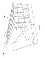
ステップ412において、検出器タイルは、複数のシンチレータ−フォトセンサアセンブリ804から生成される。例えば、図11及び図12はそれぞれ、下部及び上部斜視図を示しており、複数のシンチレータ−フォトセンサアセンブリ804が、ピン238を通じて、タイル基板242に物理的に及び電気的に接続され、それにより、タイル220を形成する。タイル基板242は更に、検出器アレイ218にタイル220を物理的に及び電気的に接続する導電性ピン1102を有することに留意されたい。
In
上述のステップの順序は制限的なものではないことが理解されるべきである。従って、他の順序がここで企図される。更に、1又は複数のステップが省かれてもよく、及び/又は1又は複数の付加のステップが含められることができ、及び/又は1又は複数のステップが同時に行われてもよい。 It should be understood that the order of the steps described above is not limiting. Accordingly, other orders are contemplated herein. Furthermore, one or more steps may be omitted and / or one or more additional steps may be included and / or one or more steps may be performed simultaneously.
図13は、個別の基板236の作成を容易にするために支持担体1302が利用される実施形態を示している。一例において、複数の基板236を含む材料シート1304が、処理され、例えば、100ミクロンより小さい厚さに薄化される。シート1304は、支持担体1302へ移される。処理エレクトロニクス240が、複数の基板236に取り付けられる。個別の基板236が、レーザ、機械式鋸等を使用して、シートから切断され、担体1302上に残る。個別の基板236が切断されたあと、担体の真空チャックフィーチャが起動される。シンチレータアレイ310は、個別の基板236に接着されるように光学的に結合され、硬化される。結果として得られるアセンブリは、ここに記述されるように、更に処理されることができる。
FIG. 13 illustrates an embodiment in which a
変更が企図される。 A change is contemplated.
別の実施形態において、処理エレクトロニクス240は、フォトセンサ基板236の外部に位置する。
In another embodiment, the
別の実施形態において、検出器モジュール222は、単一のフォトセンサ行に光学的に結合される単一のシンチレータ行を有する。
In another embodiment, the
付加的に又は代替として、他の例において、各々のシンチレータ行及び各々のフォトセンサ行がそれぞれ、単一のシンチレータ素子及び単一のフォトセンサ素子を有する。 Additionally or alternatively, in other examples, each scintillator row and each photosensor row has a single scintillator element and a single photosensor element, respectively.
本発明は、好適な実施形態に関して記述されている。変形及び変更が、上述の詳細な説明を読み理解することにより、当業者に見出されることができる。このような変形及び変更が、添付の請求項又はそれと等価なものの範囲内にある限り、すべてのこのような変形及び変更を含むとして構成されることが意図されている。 The invention has been described with reference to the preferred embodiments. Variations and modifications can be found to those skilled in the art upon reading and understanding the above detailed description. It is intended that such modifications and variations be constructed as including all such modifications and variations as long as they are within the scope of the appended claims or equivalents thereof.
Claims (13)
前記フォトセンサ基板にシンチレータアレイを光学的に結合するステップであって、前記シンチレータアレイが、少なくとも1つのシンチレータ素子の少なくとも1つのシンチレータ行を有し、前記少なくとも1つのシンチレータ行が、前記少なくとも1つのフォトセンサ行に光学的に結合され、前記少なくとも1つのシンチレータ素子が、前記少なくとも1つのフォトセンサ素子に光学的に結合される、ステップと、
前記シンチレータアレイに光学的に結合された前記フォトセンサ基板を薄化して、前記シンチレータアレイに光学的に結合された、100ミクロンより小さいオーダーの厚さを有する薄化されたフォトセンサ基板を生成するステップと、
を含む方法。 Obtaining a photosensor substrate having two opposing major surfaces, wherein one of the two opposing major surfaces has at least one photosensor row of at least one photosensor element, and the resulting photo The sensor substrate has a thickness equal to or greater than 100 microns; and
A coupling a scintillator array optically to said photosensor substrate, wherein the scintillator array having at least one scintillators row of at least one scintillators element, wherein at least one of scintillators row but the optically coupled to at least one photosensor row, wherein the at least one scintillators element, the optically coupled to the at least one photo-sensor element, comprising the steps,
Thinning the photosensor substrate optically coupled to the scintillator array to produce a thinned photosensor substrate having a thickness on the order of less than 100 microns optically coupled to the scintillator array. Steps,
Including methods.
前記複数のフォトセンサ基板にそれぞれ複数の処理エレクトロニクスを結合するステップと、
前記フォトセンサ基板に前記処理エレクトロニクスを少なくとも結合した後、前記材料シートから前記フォトセンサ基板を物理的に取り出すステップと、
を含む、請求項4乃至6のいずれか1項に記載の方法。 The photosensor substrate is part of a material sheet having a plurality of photosensor substrates, and the method further comprises:
Coupling a plurality of processing electronics to each of the plurality of photosensor substrates;
Physically removing the photosensor substrate from the material sheet after at least coupling the processing electronics to the photosensor substrate;
The method according to claim 4, comprising:
Applications Claiming Priority (3)
| Application Number | Priority Date | Filing Date | Title |
|---|---|---|---|
| US201161467044P | 2011-03-24 | 2011-03-24 | |
| US61/467,044 | 2011-03-24 | ||
| PCT/IB2012/051300 WO2012127403A2 (en) | 2011-03-24 | 2012-03-19 | Spectral imaging detector |
Publications (3)
| Publication Number | Publication Date |
|---|---|
| JP2014513279A JP2014513279A (en) | 2014-05-29 |
| JP2014513279A5 JP2014513279A5 (en) | 2015-04-16 |
| JP6071077B2 true JP6071077B2 (en) | 2017-02-01 |
Family
ID=45937487
Family Applications (1)
| Application Number | Title | Priority Date | Filing Date |
|---|---|---|---|
| JP2014500514A Active JP6071077B2 (en) | 2011-03-24 | 2012-03-19 | Method for manufacturing a spectral imaging detector |
Country Status (6)
| Country | Link |
|---|---|
| US (2) | US9281422B2 (en) |
| EP (1) | EP2689269B1 (en) |
| JP (1) | JP6071077B2 (en) |
| CN (1) | CN103443652B (en) |
| RU (1) | RU2595795C2 (en) |
| WO (1) | WO2012127403A2 (en) |
Families Citing this family (17)
| Publication number | Priority date | Publication date | Assignee | Title |
|---|---|---|---|---|
| EP2997397B1 (en) | 2013-05-16 | 2017-10-04 | Koninklijke Philips N.V. | Imaging detector |
| CN105723243B (en) | 2013-11-15 | 2019-07-09 | 皇家飞利浦有限公司 | Two-sided organic photodetector in flexible substrates |
| EP3120383B1 (en) * | 2015-01-15 | 2017-11-29 | Koninklijke Philips N.V. | Imaging detector module assembly |
| EP3532872B1 (en) * | 2016-10-26 | 2024-05-01 | Koninklijke Philips N.V. | Radiation detector scintillator with an integral through-hole interconnect |
| US10247007B2 (en) | 2017-05-02 | 2019-04-02 | General Electric Company | Airfoil shape for a turbine rotor blade |
| US10352170B2 (en) | 2017-05-02 | 2019-07-16 | General Electric Company | Airfoil shape for a turbine rotor blade |
| US10422227B2 (en) | 2017-05-02 | 2019-09-24 | General Electric Company | Airfoil shape for a turbine rotor blade |
| US10280774B2 (en) | 2017-05-03 | 2019-05-07 | General Electric Company | Turbine nozzle airfoil profile |
| US10415406B2 (en) | 2017-05-03 | 2019-09-17 | General Electric Company | Turbine nozzle airfoil profile |
| US10408072B2 (en) | 2017-05-08 | 2019-09-10 | General Electric Company | Turbine nozzle airfoil profile |
| US10436034B2 (en) | 2017-05-15 | 2019-10-08 | General Electric Company | Airfoil shape for a turbine rotor blade |
| US10533440B2 (en) | 2017-05-15 | 2020-01-14 | General Electric Company | Turbine nozzle airfoil profile |
| WO2019041172A1 (en) | 2017-08-30 | 2019-03-07 | Shenzhen United Imaging Healthcare Co., Ltd. | System, method, and detector module for pet imaging |
| CN111133338A (en) * | 2017-08-31 | 2020-05-08 | 皇家飞利浦有限公司 | Multi-layered detector with monolithic scintillator |
| DE102018200845B4 (en) | 2018-01-19 | 2021-05-06 | Siemens Healthcare Gmbh | Assembly process for the manufacture of an X-ray detector, X-ray detector and X-ray device |
| US20200185450A1 (en) * | 2018-12-06 | 2020-06-11 | Analog Devices, Inc. | Shielded integrated device packages |
| IT201900010638A1 (en) * | 2019-07-02 | 2021-01-02 | St Microelectronics Srl | SCINTILLATOR RADIATION DETECTOR AND CORRESPONDING DOSIMETER |
Family Cites Families (44)
| Publication number | Priority date | Publication date | Assignee | Title |
|---|---|---|---|---|
| JPS57172272A (en) * | 1981-04-17 | 1982-10-23 | Toshiba Corp | Multichannel type radiation detector |
| US5043582A (en) * | 1985-12-11 | 1991-08-27 | General Imagining Corporation | X-ray imaging system and solid state detector therefor |
| JPS62231222A (en) | 1986-03-31 | 1987-10-09 | Nitto Electric Ind Co Ltd | Solution for forming orientation film of liquid crystal |
| US5179284A (en) * | 1991-08-21 | 1993-01-12 | General Electric Company | Solid state radiation imager having a reflective and protective coating |
| RU2123710C1 (en) * | 1996-01-31 | 1998-12-20 | Товарищество с ограниченной ответственностью "Медтех" | Matrix x-ray receiver |
| FR2758630B1 (en) * | 1997-01-21 | 1999-04-09 | Thomson Tubes Electroniques | PROCESS FOR SEALING A SOLID STATE RADIATION DETECTOR AND DETECTOR OBTAINED THEREBY |
| US6114703A (en) * | 1997-10-21 | 2000-09-05 | The Regents Of The University Of California | High resolution scintillation detector with semiconductor readout |
| DE19841423C1 (en) * | 1998-09-10 | 1999-12-30 | Siemens Ag | Radiation detector for computer tomography apparatus |
| US6522715B2 (en) * | 2000-12-29 | 2003-02-18 | Ge Medical Systems Global Technology Company Llc | High density flex interconnect for CT detectors |
| JP5038209B2 (en) * | 2001-04-11 | 2012-10-03 | 日本結晶光学株式会社 | Radiation detector |
| JP2003084066A (en) * | 2001-04-11 | 2003-03-19 | Nippon Kessho Kogaku Kk | Component for radiation detector, radiation detector, and radiation-detection unit |
| US6510195B1 (en) * | 2001-07-18 | 2003-01-21 | Koninklijke Philips Electronics, N.V. | Solid state x-radiation detector modules and mosaics thereof, and an imaging method and apparatus employing the same |
| US6895077B2 (en) * | 2001-11-21 | 2005-05-17 | University Of Massachusetts Medical Center | System and method for x-ray fluoroscopic imaging |
| AU2003250429A1 (en) * | 2002-09-18 | 2004-04-08 | Koninklijke Philips Electronics N.V. | Radiation detector |
| US7019304B2 (en) * | 2003-10-06 | 2006-03-28 | General Electric Company | Solid-state radiation imager with back-side irradiation |
| WO2005057235A1 (en) * | 2003-12-09 | 2005-06-23 | Philips Intellectual Property & Standards Gmbh | Shielding for an x-ray detector |
| US7075091B2 (en) | 2004-01-29 | 2006-07-11 | Ge Medical Systems Global Technology Company, Llc | Apparatus for detecting ionizing radiation |
| JP2006058168A (en) * | 2004-08-20 | 2006-03-02 | Hamamatsu Photonics Kk | Radiographic imaging element and radiographic imaging method |
| DE102004052452B4 (en) * | 2004-10-28 | 2008-05-29 | Siemens Ag | Radiation detector for detecting radiation |
| JP2006145431A (en) * | 2004-11-22 | 2006-06-08 | Ge Medical Systems Global Technology Co Llc | Radiation detector, radiographical imaging device, radiographical ct unit, and manufacturing method for radiation detector |
| CN101163988B (en) * | 2005-04-22 | 2012-06-13 | 皇家飞利浦电子股份有限公司 | Digital silicon photomultiplier for tof-pet |
| JP5268633B2 (en) | 2005-04-26 | 2013-08-21 | コーニンクレッカ フィリップス エレクトロニクス エヌ ヴィ | Detector array for spectral CT |
| US7968853B2 (en) * | 2005-04-26 | 2011-06-28 | Koninklijke Philips Electronics N.V. | Double decker detector for spectral CT |
| US7399972B2 (en) * | 2005-06-09 | 2008-07-15 | Nihon Kessho Kogaku Co., Ltd. | Component for radiation detector and radiation detector |
| EP1934633A2 (en) * | 2005-10-05 | 2008-06-25 | Koninklijke Philips Electronics N.V. | Computed tomography detector using thin circuits |
| US8710448B2 (en) * | 2006-03-30 | 2014-04-29 | Koninklijke Philips N.V. | Radiation detector array |
| US7692156B1 (en) * | 2006-08-23 | 2010-04-06 | Radiation Monitoring Devices, Inc. | Beam-oriented pixellated scintillators for radiation imaging |
| US7608837B2 (en) * | 2006-11-24 | 2009-10-27 | Tower Semiconductor Ltd. | High resolution integrated X-ray CMOS image sensor |
| US8586933B2 (en) * | 2007-04-25 | 2013-11-19 | Koninklijke Philips N.V. | Radiation detector having a split laminate optical coupling |
| CN104330816A (en) * | 2007-11-09 | 2015-02-04 | 皇家飞利浦电子股份有限公司 | Protection of hygroscopic scintillators |
| JP2009147212A (en) * | 2007-12-17 | 2009-07-02 | Nippon Kessho Kogaku Kk | Photo detector and photo detection apparatus employing the photo detector |
| WO2009083852A2 (en) * | 2007-12-21 | 2009-07-09 | Koninklijke Philips Electronics N.V. | Radiation-sensitive detector with a scintillator in a composite resin |
| JP4650586B2 (en) * | 2008-02-04 | 2011-03-16 | 株式会社島津製作所 | Radiation detector and tomography apparatus provided with the same |
| JP4877417B2 (en) * | 2008-06-05 | 2012-02-15 | 株式会社島津製作所 | Manufacturing method of radiation detector |
| US7737409B2 (en) * | 2008-06-12 | 2010-06-15 | Analog Devices, Inc. | Silicon detector and method for constructing silicon detectors |
| WO2010010608A1 (en) * | 2008-07-22 | 2010-01-28 | 株式会社島津製作所 | Method for manufacturing radiation tomographic equipment |
| CN105044758B (en) * | 2008-11-18 | 2022-06-14 | 皇家飞利浦电子股份有限公司 | Spectral imaging detector |
| CN102216807B (en) * | 2008-11-21 | 2016-08-17 | 皇家飞利浦电子股份有限公司 | The assemble method of tiled radiation detector |
| KR101497498B1 (en) * | 2008-12-19 | 2015-03-03 | 삼성전자주식회사 | Method and appratus for acquiring penetration images of radioactive ray |
| JP5247486B2 (en) * | 2009-01-16 | 2013-07-24 | 浜松ホトニクス株式会社 | Back-illuminated photodiode array and radiation detector |
| US8373132B2 (en) * | 2009-02-06 | 2013-02-12 | Koninklijke Philips Electronics N. V. | Radiation detector with a stack of scintillator elements and photodiode arrays |
| US9164700B2 (en) | 2009-03-05 | 2015-10-20 | Sandisk Il Ltd | System for optimizing the transfer of stored content in response to a triggering event |
| US8466421B2 (en) * | 2010-07-30 | 2013-06-18 | Varian Medical Systems Inc. | Radiation detector with multiple operating schemes |
| JP5422581B2 (en) * | 2011-01-31 | 2014-02-19 | 富士フイルム株式会社 | Radiation image detection apparatus and manufacturing method thereof |
-
2012
- 2012-03-19 RU RU2013147397/28A patent/RU2595795C2/en not_active IP Right Cessation
- 2012-03-19 JP JP2014500514A patent/JP6071077B2/en active Active
- 2012-03-19 EP EP20120713356 patent/EP2689269B1/en active Active
- 2012-03-19 US US14/006,703 patent/US9281422B2/en active Active
- 2012-03-19 CN CN201280014657.2A patent/CN103443652B/en active Active
- 2012-03-19 WO PCT/IB2012/051300 patent/WO2012127403A2/en active Application Filing
-
2016
- 2016-02-03 US US15/014,297 patent/US9599725B2/en active Active
Also Published As
| Publication number | Publication date |
|---|---|
| US9599725B2 (en) | 2017-03-21 |
| WO2012127403A3 (en) | 2012-12-27 |
| US20160154121A1 (en) | 2016-06-02 |
| WO2012127403A2 (en) | 2012-09-27 |
| JP2014513279A (en) | 2014-05-29 |
| CN103443652B (en) | 2017-02-15 |
| US9281422B2 (en) | 2016-03-08 |
| RU2595795C2 (en) | 2016-08-27 |
| US20140015081A1 (en) | 2014-01-16 |
| RU2013147397A (en) | 2015-04-27 |
| EP2689269B1 (en) | 2015-05-13 |
| EP2689269A2 (en) | 2014-01-29 |
| CN103443652A (en) | 2013-12-11 |
Similar Documents
| Publication | Publication Date | Title |
|---|---|---|
| JP6071077B2 (en) | Method for manufacturing a spectral imaging detector | |
| JP6247285B2 (en) | Multi-layer horizontal computed tomography system and method having at least one thin photosensor disposed between at least two scintillator array layers | |
| JP5455620B2 (en) | Radiation detector and apparatus including the detector | |
| US9835733B2 (en) | Apparatus for detecting X-rays | |
| NL2008201C2 (en) | Detector systems with anode incidence face and methods of fabricating the same. | |
| JP6445978B2 (en) | Imaging detector | |
| RU2647206C1 (en) | Sensor device and visualization system for detecting radiation signals | |
| US10283557B2 (en) | Radiation detector assembly | |
| JP2019533812A (en) | Radiation detector scintillator with integrated through-hole interconnect | |
| WO2017116523A1 (en) | Radiation detector assembly | |
| JP6194126B2 (en) | Modular imaging detector ASIC | |
| JP2007086077A (en) | Manufacturing method of detector, and the detector | |
| JP2019531464A (en) | 3D solid-state imaging photodetector | |
| US10181493B2 (en) | Radiation detector system of radiation imaging modality |
Legal Events
| Date | Code | Title | Description |
|---|---|---|---|
| A521 | Request for written amendment filed |
Free format text: JAPANESE INTERMEDIATE CODE: A523 Effective date: 20150225 |
|
| A621 | Written request for application examination |
Free format text: JAPANESE INTERMEDIATE CODE: A621 Effective date: 20150225 |
|
| A977 | Report on retrieval |
Free format text: JAPANESE INTERMEDIATE CODE: A971007 Effective date: 20160125 |
|
| A131 | Notification of reasons for refusal |
Free format text: JAPANESE INTERMEDIATE CODE: A131 Effective date: 20160128 |
|
| A601 | Written request for extension of time |
Free format text: JAPANESE INTERMEDIATE CODE: A601 Effective date: 20160427 |
|
| A521 | Request for written amendment filed |
Free format text: JAPANESE INTERMEDIATE CODE: A523 Effective date: 20160728 |
|
| TRDD | Decision of grant or rejection written | ||
| A01 | Written decision to grant a patent or to grant a registration (utility model) |
Free format text: JAPANESE INTERMEDIATE CODE: A01 Effective date: 20161206 |
|
| A61 | First payment of annual fees (during grant procedure) |
Free format text: JAPANESE INTERMEDIATE CODE: A61 Effective date: 20161222 |
|
| R150 | Certificate of patent or registration of utility model |
Ref document number: 6071077 Country of ref document: JP Free format text: JAPANESE INTERMEDIATE CODE: R150 |
|
| R250 | Receipt of annual fees |
Free format text: JAPANESE INTERMEDIATE CODE: R250 |
|
| R250 | Receipt of annual fees |
Free format text: JAPANESE INTERMEDIATE CODE: R250 |
|
| R250 | Receipt of annual fees |
Free format text: JAPANESE INTERMEDIATE CODE: R250 |
|
| R250 | Receipt of annual fees |
Free format text: JAPANESE INTERMEDIATE CODE: R250 |