JP6069880B2 - Rack device, rack system, and housing structure - Google Patents
Rack device, rack system, and housing structure Download PDFInfo
- Publication number
- JP6069880B2 JP6069880B2 JP2012099266A JP2012099266A JP6069880B2 JP 6069880 B2 JP6069880 B2 JP 6069880B2 JP 2012099266 A JP2012099266 A JP 2012099266A JP 2012099266 A JP2012099266 A JP 2012099266A JP 6069880 B2 JP6069880 B2 JP 6069880B2
- Authority
- JP
- Japan
- Prior art keywords
- space
- air conditioner
- electronic device
- rack
- housing
- Prior art date
- Legal status (The legal status is an assumption and is not a legal conclusion. Google has not performed a legal analysis and makes no representation as to the accuracy of the status listed.)
- Active
Links
Images


Classifications
-
- F—MECHANICAL ENGINEERING; LIGHTING; HEATING; WEAPONS; BLASTING
- F24—HEATING; RANGES; VENTILATING
- F24F—AIR-CONDITIONING; AIR-HUMIDIFICATION; VENTILATION; USE OF AIR CURRENTS FOR SCREENING
- F24F13/00—Details common to, or for air-conditioning, air-humidification, ventilation or use of air currents for screening
- F24F13/32—Supports for air-conditioning, air-humidification or ventilation units
-
- F—MECHANICAL ENGINEERING; LIGHTING; HEATING; WEAPONS; BLASTING
- F24—HEATING; RANGES; VENTILATING
- F24F—AIR-CONDITIONING; AIR-HUMIDIFICATION; VENTILATION; USE OF AIR CURRENTS FOR SCREENING
- F24F13/00—Details common to, or for air-conditioning, air-humidification, ventilation or use of air currents for screening
- F24F13/08—Air-flow control members, e.g. louvres, grilles, flaps or guide plates
- F24F13/10—Air-flow control members, e.g. louvres, grilles, flaps or guide plates movable, e.g. dampers
- F24F13/14—Air-flow control members, e.g. louvres, grilles, flaps or guide plates movable, e.g. dampers built up of tilting members, e.g. louvre
-
- H—ELECTRICITY
- H05—ELECTRIC TECHNIQUES NOT OTHERWISE PROVIDED FOR
- H05K—PRINTED CIRCUITS; CASINGS OR CONSTRUCTIONAL DETAILS OF ELECTRIC APPARATUS; MANUFACTURE OF ASSEMBLAGES OF ELECTRICAL COMPONENTS
- H05K5/00—Casings, cabinets or drawers for electric apparatus
- H05K5/02—Details
- H05K5/0213—Venting apertures; Constructional details thereof
-
- H—ELECTRICITY
- H05—ELECTRIC TECHNIQUES NOT OTHERWISE PROVIDED FOR
- H05K—PRINTED CIRCUITS; CASINGS OR CONSTRUCTIONAL DETAILS OF ELECTRIC APPARATUS; MANUFACTURE OF ASSEMBLAGES OF ELECTRICAL COMPONENTS
- H05K7/00—Constructional details common to different types of electric apparatus
- H05K7/20—Modifications to facilitate cooling, ventilating, or heating
- H05K7/20536—Modifications to facilitate cooling, ventilating, or heating for racks or cabinets of standardised dimensions, e.g. electronic racks for aircraft or telecommunication equipment
- H05K7/20609—Air circulating in closed loop within cabinets wherein heat is removed through air-to-liquid heat-exchanger
-
- H—ELECTRICITY
- H05—ELECTRIC TECHNIQUES NOT OTHERWISE PROVIDED FOR
- H05K—PRINTED CIRCUITS; CASINGS OR CONSTRUCTIONAL DETAILS OF ELECTRIC APPARATUS; MANUFACTURE OF ASSEMBLAGES OF ELECTRICAL COMPONENTS
- H05K7/00—Constructional details common to different types of electric apparatus
- H05K7/20—Modifications to facilitate cooling, ventilating, or heating
- H05K7/20709—Modifications to facilitate cooling, ventilating, or heating for server racks or cabinets; for data centers, e.g. 19-inch computer racks
- H05K7/20718—Forced ventilation of a gaseous coolant
- H05K7/20736—Forced ventilation of a gaseous coolant within cabinets for removing heat from server blades
-
- H—ELECTRICITY
- H05—ELECTRIC TECHNIQUES NOT OTHERWISE PROVIDED FOR
- H05K—PRINTED CIRCUITS; CASINGS OR CONSTRUCTIONAL DETAILS OF ELECTRIC APPARATUS; MANUFACTURE OF ASSEMBLAGES OF ELECTRICAL COMPONENTS
- H05K7/00—Constructional details common to different types of electric apparatus
- H05K7/20—Modifications to facilitate cooling, ventilating, or heating
- H05K7/20709—Modifications to facilitate cooling, ventilating, or heating for server racks or cabinets; for data centers, e.g. 19-inch computer racks
- H05K7/20754—Air circulating in closed loop within cabinets
Landscapes
- Engineering & Computer Science (AREA)
- Microelectronics & Electronic Packaging (AREA)
- Physics & Mathematics (AREA)
- Thermal Sciences (AREA)
- General Engineering & Computer Science (AREA)
- Chemical & Material Sciences (AREA)
- Combustion & Propulsion (AREA)
- Mechanical Engineering (AREA)
- Computer Hardware Design (AREA)
- Aviation & Aerospace Engineering (AREA)
- Cooling Or The Like Of Electrical Apparatus (AREA)
Description
本発明は、ラック装置、ラックシステム及び筐体構造に関する。 The present invention relates to a rack device, a rack system, and a housing structure.
電子機器を搭載するラック装置では、電子機器が発する熱でラック装置内部の温度が上昇してしまう。ラック装置内部の温度が上昇した場合、電子機器の動作が不安定になるおそれがある。そこで、ラック装置の内部の空気を冷却することが行われている。 In a rack apparatus on which electronic equipment is mounted, the temperature inside the rack apparatus rises due to heat generated by the electronic equipment. When the temperature inside the rack device rises, the operation of the electronic device may become unstable. Therefore, cooling of the air inside the rack apparatus is performed.
近年、ラック装置内部の冷却のために、空調機能を備えたラック装置が開発されている。このようなラック装置では、ラック装置に搭載された空調機能により、ラック装置の内部温度が安定化し、搭載された電子機器の動作が安定化する。 In recent years, a rack apparatus having an air conditioning function has been developed for cooling the inside of the rack apparatus. In such a rack apparatus, the internal temperature of the rack apparatus is stabilized by the air conditioning function mounted on the rack apparatus, and the operation of the mounted electronic device is stabilized.
このような空調機器を備えたラック装置として、ラック装置下部にクーラーを配置し、空気を循環させ電子機器を冷却する従来技術がある。 As a rack apparatus provided with such an air conditioner, there is a conventional technique in which a cooler is disposed at the lower part of the rack apparatus and air is circulated to cool the electronic apparatus.
しかしながら、ラック装置の設置場所にはスペースの制限があることが多い。特に学校や企業などのオフィスにラックを配置する場合、ラック装置を配置するスペースの制限はより厳しくなる。そこで、ラック装置をコンパクトにすることで、ラック装置が占有するスペースを小さくし、オフィスのスペースを有効利用することが好ましい。そのため、空調機能を搭載したラック装置においても、いっそうの小型化が好ましい。また、ラック装置を小型化することで製造コストを抑えることもできる。 However, there are often space limitations in the installation location of the rack device. In particular, when a rack is arranged in an office such as a school or a company, the restriction on the space for arranging the rack device becomes more severe. Therefore, it is preferable to make the rack device compact so as to reduce the space occupied by the rack device and effectively use the office space. Therefore, further downsizing is preferable also in a rack apparatus equipped with an air conditioning function. Further, the manufacturing cost can be reduced by downsizing the rack device.
ところが、ラック装置に空調機能を搭載する場合、ラック装置は、筐体内に電子機器を搭載する場所の他に、空調機器を搭載する場所を有する。そこで、ラック装置を小型化するためには、ラック装置内部に搭載する空調機器としてコンパクトな空調機器を使用することになる。しかし、コンパクトな空調機器では、空調機器自体に余分な熱を逃がすスペースが乏しい。そのため、コンパクトな空調機器を隙間なくラックに搭載させた場合、空調機器自体の熱がラックに搭載された電子機器の装置に影響を与えるおそれがある。そのため、コンパクトな空調機器をラックに搭載するには、空調機器の周りにスペースを設けることになる。 However, when the air conditioning function is mounted on the rack device, the rack device has a place where the air conditioner is mounted in addition to the place where the electronic device is mounted in the housing. Therefore, in order to reduce the size of the rack device, a compact air conditioner is used as an air conditioner mounted inside the rack device. However, in a compact air conditioner, there is not enough space for the heat to escape to the air conditioner itself. Therefore, when a compact air conditioner is mounted on a rack without a gap, the heat of the air conditioner itself may affect the device of the electronic device mounted on the rack. Therefore, in order to mount a compact air conditioner on the rack, a space is provided around the air conditioner.
空調機器の周りにスペースを設けた場合、従来技術などを用いた場合、空調機器の排気口と吸気口が同じ空間に存在することになり、暖められた空気と冷めた空気との混合などが発生してしまい、冷却効率が悪くなってしまうおそれがある。 When a space is provided around the air conditioner, when the conventional technology is used, the air outlet and the air intake of the air conditioner will be in the same space, and mixing of warm and cold air will occur. It may occur and cooling efficiency may deteriorate.
開示の技術は、上記に鑑みてなされたものであって、冷却効率を向上させたラック装置、ラックシステム及び筐体構造を提供することを目的とする。 The disclosed technology has been made in view of the above, and an object thereof is to provide a rack device, a rack system, and a housing structure with improved cooling efficiency.
本願の開示するラック装置、ラックシステム及び筐体構造は、筐体は、電子機器および空調機が搭載される。仕切板は、前記筐体内の空間を、前記電子機器が配置される第1の空間と前記空調機が配置される第2の空間とに仕切る。遮蔽部材は、開閉可能であり、前記第2の空間を、前記空調機の排気口が配置され、前記第1の空間における前記電子機器の吸気側に繋がる空間と、前記空調機の吸気口が配置され、前記第1の空間における前記電子機器の排気側に繋がる空間とに区分けする。 In the rack device, the rack system, and the housing structure disclosed in the present application, an electronic device and an air conditioner are mounted on the housing. Partition plate, dividing said housing space, and a second space in which the first space and the air conditioner in which the electronic device is arranged is arranged. The shielding member is capable of opening and closing, the second space, the outlet of the air conditioner is disposed, a space leading to the intake side of the electronic device in the first space, the air inlet of the air conditioner The first space is divided into a space connected to the exhaust side of the electronic device.
本願の開示するラック装置、ラックシステム及び筐体構造の一つの態様によれば、冷却効率を向上させるという効果を奏する。 According to one aspect of the rack device, the rack system, and the housing structure disclosed in the present application, there is an effect of improving the cooling efficiency.
以下に、本願の開示するラック装置、ラックシステム及び筐体構造の実施例を図面に基づいて詳細に説明する。なお、以下の実施例により本願の開示するラック装置、ラックシステム及び筐体構造が限定されるものではない。 Hereinafter, embodiments of a rack apparatus, a rack system, and a housing structure disclosed in the present application will be described in detail with reference to the drawings. The rack device, the rack system, and the housing structure disclosed in the present application are not limited by the following embodiments.
図1は、実施例に係るラック装置の透視斜視図である。図1に示すように、筐体1は、XY平面、YZ平面及びXZ平面を有する直方体である。そして、筐体1は、XY平面が地面に接する、または、筐体1のXY平面に取り付けられた移動用部品(例えばキャスターやストッパー等)が地面に接する状態で配置されている。以下では、X方向を筐体1の幅方向、Y方向を筐体1の奥行き方向、Z方向を筐体1の高さ方向という。また、図1のZ矢印が向かう方向を上方向、Z矢印と逆向きの方向を下方向という。また、Y矢印が向かう方向を後ろとし、Y矢印と逆向きの方向を前とする。そして、筐体1の前側を筐体1の正面とする。また、X矢印の向かう方向を右、X矢印と逆向きの方向を左とする。
FIG. 1 is a perspective view of the rack device according to the embodiment. As illustrated in FIG. 1, the
図1に示すように、筐体1は、仕切板10で上部空間13と、下部空間14に分けられている。筐体1の上部空間13には、電子機器3が搭載されている。電子機器3とは、例えば、サーバやネットワーク機器などである。また、筐体1の下部空間14には空調機2の室内機が搭載されている。ここで、本実施例の空調機2は、室内機と室外機に分かれている。室内機はラック装置の筐体1に搭載され、室外機はラック装置が設置されたオフィスの外に置かれている。以下の説明では、空調機2の室内機を、空調機2と呼ぶ場合がある。また、空調機2は上部に吸気口22を有し、前方下部に排気口21を有している。上部空間13が、「第1の空間」の一例にあたる。また、下部空間14が、「第2の空間」の一例にあたる。
As shown in FIG. 1, the
さらに、仕切板10から空調機2に向けて遮蔽板11が配置されている。遮蔽板11は、筐体1の両側面に接し、且つ空調機2に接することで、後述するように、空調機2の吸気口が配置された空間と排気口が配置された空間とを分けている。さらに、筐体1の上部空間13における電子機器3が搭載される部分の正面側には、左右にサイド仕切板12が配置されている。
Further, a
電子機器3は、筐体1の正面から奥行き方向に向かって挿入され配置される。そして、電子機器3は、筐体1の内部の正面側から空気を吸気し、CPU(Central Processing Unit)などの内部に配置された各種発熱部材を吸気した空気で冷やす。そして、電子機器3は、暖められた空気を筐体1の内部の後ろ側に排気する。
The
また、ラック装置は、筐体1の周囲にドアなどの外壁が設けられ、内部が密閉された状態となっている。内部が密閉されているため、後述する空調機2から排出される冷たい空気や電子機器3から排出される暖かい空気はラック装置外に漏れることなく循環する。これにより、ラック装置外部へ暖かい空気が漏れることによるオフィスの温度上昇を抑えることができ、また冷却された空気による冷却効率を向上させることができる。また、筐体1外部の埃などが入り込むことを防止することが可能になる。
Further, the rack device is provided with an outer wall such as a door around the
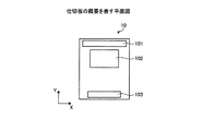
図2は、仕切板の概要を表す平面図である。仕切板10は、筐体1の後方に排気開口101を有している。さらに、仕切板10は、排気開口101の前に排気開口102を有している。また、仕切板10は、筐体1の前方に吸気開口103を有している。ここで、排気開口101、排気開口102及び吸気開口103における排気及び吸気とは電子機器3を基準とした名前であり、排気とは電子機器3が暖かい空気を排出することを表し、吸気とは電子機器3が冷たい空気を吸気することを表している。すなわち、電子機器3の後方から排気された空気は、排気開口101を通過して筐体1の下部空間14に送られる。さらに、電子機器3の中央部の熱で暖められた空気は、排気開口102を通過して筐体1の下部空間14に送られる。また、筐体1の下部空間14の空気は、吸気開口103を通過して上部空間13に送られ、電子機器3に吸気される。
FIG. 2 is a plan view illustrating an outline of the partition plate. The
本実施例では、吸気開口103は、排気開口101よりも小さい開口を有している。また、排気用の開口部は、排気開口101及び排気開口102があるが、吸気用の開口部は、吸気開口103のみであり、吸気用の開口部全体としてみても、排気用の開口部の方が、吸気用の開口部よりも大きい。吸気開口103を小さくすることにより、下部空間14の吸気開口103側の圧力を高くすることができ、吸気開口103から上部空間13へ噴出す空気の風速を上げることができ、風量を増やすことができる。ここで、筐体1の中の一番上に搭載された電子機器3まで冷たい空気が届くことが好ましい。また、搭載されている全ての電子機器3に冷たい空気がいきわたる風量があることが好ましい。このため、吸気開口103の大きさは、例えば、風速と風量の関係を基に筐体1のサイズなどに応じて決定されることが好ましい。
In the present embodiment, the
また、ネットワーク機器は、サーバやストレージなどに比べて短い。そのため、ネットワーク機器の排気は、排気開口102の位置で排気される。そのため、ネットワーク機器を仕切板10の直ぐ上の上部空間13に搭載した場合やネットワーク機器のみを上部空間13に搭載した場合に、排気開口102から暖かい空気が下部空間14へ送られ、冷却効率を向上させることができる。
Network devices are shorter than servers and storage. Therefore, the exhaust of the network device is exhausted at the position of the
図3は、実施例に係るラック装置の正面図である。本実施例では、12(U)のラックを例に説明する。図3は、上部空間13に電子機器3が搭載されていない状態を表している。例えば、上部空間13は、高さ565mmである。また、例えば、下部空間14は、高さ395mmである。また、図3では、ストッパー16及びキャスター17が地面に接して筐体1を固定している。
FIG. 3 is a front view of the rack device according to the embodiment. In this embodiment, a 12 (U) rack will be described as an example. FIG. 3 shows a state where the
上部空間13には、正面からみて左右にサイド仕切板12が配置されている。サイド仕切板12は、筐体1の左右の側面から電子機器3を固定する柱の位置まで延びており、電子機器3の吸気側の空間と排気側の空間とを区分けする。サイド仕切板12は、電子機器3で発生した熱により暖められた空気が電子機器3の吸気側に回らないように、暖められた空気の移動を遮蔽している。電子機器3を固定する柱の間の間隔は、例えば、451mmである。
また、サイド仕切板12は、熱戻り防止パネル121を有している。熱戻り防止パネル121は複数の切り込みを備えた、弾力性を有する部材である。電子機器3の前面に接続されたケーブル類は、熱戻り防止パネル121の切り込みを通過して背面に回される。熱戻り防止パネル121は、例えば、筐体1の正面から見て35mm×150mmの長方形をしている。サイド仕切板12の内側には、電子機器を固定するマウントアングル15が設けられている。マウントアングル15には、電子機器を適当な位置で固定するための穴が縦方向に並んでいる。
Further, the
図3では、下部空間14の中に、遮蔽板11及び空調機2の排気口が見えている。遮蔽板11は、空調機2の前面に延び、遮蔽板11の下側に空調機2の排気口の部分が出ている。また、遮蔽板11は、後述するように前面に向かって持ち上げることが可能である。
In FIG. 3, the shielding
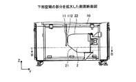
図4は、実施例に係るラック装置の側面断面図である。また、図5は、下部空間の部分を拡大した側面断面図である。 FIG. 4 is a side sectional view of the rack apparatus according to the embodiment. FIG. 5 is an enlarged side sectional view of the lower space.
図4及び図5に示すように、空調機2は、下部空間14の後方に配置されている。空調機2は、例えば、家庭用のエアコンの室内機などを用いてもよい。本実施例では、空調機2は、図5に示すように、前方下部に排気口21を有し、上部に吸気口22を有している。そして、空調機2は、吸気口22から吸入した空気を冷し、排気口21から冷した空気を排出する。排気口21からの冷たい空気の排気方向は、吸気開口103から送り出される風量が大きくなるように適宜設定されることが好ましい。
As shown in FIGS. 4 and 5, the
また、本実施例の空調機2は、空調機2の上部にも空間を有している。これは、空調機2の上部に設けられた吸気口22から空気を吸い込むことや、空調機2の熱を逃がすなどの理由からである。さらに、本実施例では、空調機2の下部にも空間を有している。ただし、空調機2は、筐体1の底面に接触させて配置してもよい。この場合、空調機2の排気方向は筐体1の底面に向かう方向でないことが好ましい。
In addition, the
図5では図示していないが、空調機2からドレンホースが外部に延びている。空調機2は、主に運転開始時に水分が発生する。ドレンホースは、空調機2で発生した水分を排水溝へ排出する。図6は、図5のB−B断面矢視図である。例えば、空調機2から出るドレンホース23は、筐体1の底面後方から外部の排水溝へ出される。また、空調機2から延びる冷媒配管41、42は、筐体1の底面後方から外部に出され、室外機4に繋がれる。
Although not shown in FIG. 5, the drain hose extends from the
ここで、本実施例では、空調機2を下部空間14に配置している。これにより、電子機器3を上部空間13に配置することができ、電子機器3のメンテナンスを容易に行える。また、空調機2で発生した水分による水漏れが万一起きた場合でも、水漏による電子機器3への影響を軽減することができる。
Here, in this embodiment, the
遮蔽板11は、仕切板10から下方向に延出し、空調機2の前面部分に接触するように配置されている。さらに、遮蔽板11は、図4の点線111で示す状態の位置まで、筐体1の幅方向を軸に回動する。遮蔽板11は、点線111の状態で固定される。例えば、遮蔽板11の先端に嵌合部材を設け、且つ仕切板10の遮蔽版11の先端が接触する位置に遮蔽板11の嵌合部材の組になる嵌合部材を設けることで、遮蔽板11を嵌合部材により固定することができる。また、遮蔽板11の先端に磁石を配置し、且つ遮蔽板11の先端部が接触する場所に磁石を配置して、遮蔽板11が点線111の位置まで回動することで磁力により固定することができる。このように、遮蔽板11を回動させることで、空調機2への筐体1の前面方向からのアクセスを容易にしている。例えば、本実施例では、遮蔽板11を回動させることで、空調機2の前面の蓋を開けることができ、内部の掃除を容易に行うことができる。
The shielding
遮蔽板11は、空調機2の排気口21から排気される冷たい空気が溜まる空間と、空調機2の吸気口22から吸気される電子機器3が排出した暖かい空気が溜まる空間とを分けている。このように遮蔽板11を設けることで、空調機2の周りにスペースを設けて筐体1の内部に配置した場合でも、暖かい空気と冷たい空気とを分離でき、冷却効率を向上させることができる。
The shielding
ここで、遮蔽板11は、図5に示すように、空調機2の排気口21から仕切板10に向かって延びるラック装置の前後の面に平行な壁に沿って排気口21の付近まで延びている。さらに、本実施例では、遮蔽板11の空調機2に接する面にはスポンジなどの緩衝材112が配置されている。緩衝材112が遮蔽板11と空調機2によって挟まれることで、遮蔽板11と空調機2との隙間を通過する空気量を減少させることができ、単に遮蔽板11を空調機2に接する状態で配置した場合に比べて、吸気口22の付近の暖かい空気と排気口21付近の冷たい空気とをより確実に遮蔽することができる。また、緩衝材112を介して遮蔽板11が空調機2に接することで、空調機2の動作によるがたつきを抑えることができる。
Here, as shown in FIG. 5, the shielding
図7は、図4のA−A断面矢視図である。図4及び図7に示すように、吸気開口103は、筐体1の前方に設けられている。すなわち、吸気開口103は、仕切板10、遮蔽板11、空調機2及び筐体1で囲われた、排気口21から排出された冷たい空気が溜まる空間の空気の逃げ道となっている。例えば、吸気開口103は、幅680mm、奥行き95mmの長方形の開口を有している。
7 is a cross-sectional view taken along the line AA in FIG. As shown in FIGS. 4 and 7, the
排気開口101は、筐体1の後方に設けられている。さらに、排気開口102は、排気開口101の前方で遮蔽板11の位置よりも後方の位置に設けられている。すなわち、排気開口101及び排気開口102は、仕切板10、遮蔽板11、空調機2及び筐体1で囲われた、電子機器3から排出された暖かい空気が溜まる空間への空気の侵入口となっている。例えば、排気開口102は、幅440mm、奥行き280mmの長方形の開口を有している。
The
次に、図8を参照して、実施例に係るラックにおける全体的な空気の流れについて説明する。図8は、実施例に係るラック装置における全体的な空気の流れを説明するための図である。内部がドットパターンで表される矢印Pは電子機器3からの排気を表し、内部が斜線パターンで表される矢印Qは電子機器3による吸気を表している。
Next, an overall air flow in the rack according to the embodiment will be described with reference to FIG. FIG. 8 is a diagram for explaining the overall air flow in the rack apparatus according to the embodiment. An arrow P whose inside is represented by a dot pattern represents exhaust from the
電子機器3から排気された暖かい空気は、排気開口101及び排気開口102を通過して、上部空間13から下部空間14に送られる。下部空間14に送られた暖かい空気は、吸気口22から空調機2に吸い込まれる。そして、空調機2は、吸い込んだ空気を冷し、排気口21から排出する。排気口21から排出された冷たい空気は、吸気開口103を通過して下部空間14から上部空間13に送られる。そして、上部空間13に送られた冷たい空気は、電子機器3に吸い込まれる。
Warm air exhausted from the
さらに、図9を参照して、実施例に係るラック装置における、冷たい空気が溜まるコールドエリアと、暖かい空気が溜まるホットエリアについて説明する。図9は、実施例に係るラック装置におけるコールドエリアとホットエリアを表す図である。本実施例に係るラック装置では、電子機器3自体、電子機器3が搭載されていない棚については電子機器3の正面に沿った位置に貼られた遮蔽版、サイド仕切板12および遮蔽板11とで区切られるコールドエリア401とホットエリア402とに分けられる。コールドエリア401は、左下に向かう斜線で表される領域である。また、ホットエリア402は、右下に向かう斜線で表される領域である。上述したように、サイド仕切板12は、電子機器3が吸入する冷たい空気と電子機器3により暖められた空気とが混合しないように空間を区分けする。また、遮蔽板11は、空調機2が吸入する暖かい空気と空調機2が排出する冷たい空気とが混合しないように空間を区分けする。このため、コールドエリア401の空気とホットエリア402との空気は混合しない。これにより、空調機2によるラック装置内の空気の冷却効率を向上させることができる。
Furthermore, with reference to FIG. 9, the cold area in which the cold air accumulates and the hot area in which the warm air accumulates in the rack apparatus according to the embodiment will be described. FIG. 9 is a diagram illustrating a cold area and a hot area in the rack apparatus according to the embodiment. In the rack apparatus according to the present embodiment, the
なお、上部空間13において電子機器3が設置されていない棚部分には、筐体1の正面側に遮蔽板を取り付けられる。この構成にすることで、電子機器3が設置されていない棚部分は筐体1内部の前後空間の移動する空気の量を低減することが可能になる。また、遮蔽板は、筐体1に設置される電子機器3の前正面に沿って取り付けられることが望ましい。これにより、電子機器3自体が発する熱をホットエリアに位置させることができる。
Note that a shielding plate is attached to the front side of the
本実施例の筐体1は、サイド仕切板12の面と電子機器3の正面とは奥行き方向の位置が同じであるものとする。
In the
さらに、図8に記載するように、本実施例に係る空調機2の室内機は、冷媒配管41及び冷媒配管42により筐体1の外部に配置された室外機に接続されている。ここでは、空調機2の室外機を、室外機4として説明する。冷媒配管41及び冷媒配管42は、例えば銅製である。本実施例では、室外機4は、オフィスの外に配置されている。そして、室外機4は、低圧気体を高圧気体に変換する圧縮機と高圧液体に変換する凝縮機が、空調機2では高圧液体を低圧液体に変換する膨張機と低圧気体に変換する蒸発機が冷媒配管41及び42でつながり、冷媒サイクルを構成する仕組みとなっている。室外機4の凝縮機では冷媒を気体から液体に変換時に放熱し、外に排出され、空調機2の蒸発機では冷媒を液体から気体に変換するときに室内空気の熱を奪い空気を冷却する仕組みとなっている。
Furthermore, as described in FIG. 8, the indoor unit of the
さらに、図3に戻ってラック装置の他の機能について説明する。ここでは、空調機2を室外機と室内機に分けて説明する。筐体1には、運転ランプ301と異常ランプ302とが設けられている。運転ランプ301は、空調機2の室内機が稼動している状態で点灯する。異常ランプ302は、空調機2の室内機又は室外機に異常が発生した場合に点灯する。異常とは、空調機2の室内機又は室外機が、通信、サーミスタ、制御部、ファンモータ、冷凍サイクルなどの異常が発生したと判定した場合である。
Furthermore, returning to FIG. 3, other functions of the rack apparatus will be described. Here, the
ここで、図10を参照して、異常ランプ302の詳細を説明する。図10は、異常ランプと運転ランプ接続を表す概略図である。図10では、空調機2の室内機及び室外機を、それぞれ室内機201及び室外機202として表している。異常ランプ302は、空調機2の室内機201と異常時出力用ケーブル203で接続されている。また、室外機202は、室内機201と接続されている。そして、室内機201は、上述した各異常を検出した場合、異常時出力用ケーブル203に電流を流す。これにより、異常ランプ302が点灯する。また、室内機201のコンセント204を差し込むことで、運転ランプ303が点灯する。
Here, the details of the
また、温度異常を検知するため、温度センサをラック装置内部に取り付けることが好ましい。例えば、図4の温度センサ304のように、空調機2の室内機の吸気口の付近に取り付けてもよい。
Moreover, in order to detect temperature abnormality, it is preferable to attach a temperature sensor inside a rack apparatus. For example, like the
以上に説明したように、本実施例に係るラック装置は、空調機の室内機の排気口が存在する空間と吸気口が存在する空間とを遮蔽板で区分けしている。このように遮蔽板を配置することで、コンパクトな空調機の室内機の周りにスペースを設けた場合でも、電子機器で暖められた空気と空調機が冷却した空気とは混ざり合わない。また、電子機器の両脇のサイド仕切板により電子機器の周りの空間も冷たい空気が滞留する空間と暖かい空気が滞留する区間とは区分けされている。このため、ラック全体において、コールドエリアとホットエリアとが確実に分離されている。これにより、ラック装置を小型化しつつ冷却効果を向上することができる。 As described above, in the rack apparatus according to the present embodiment, the space where the exhaust port of the indoor unit of the air conditioner exists and the space where the intake port exist are separated by the shielding plate. By arranging the shielding plate in this way, even when a space is provided around the indoor unit of a compact air conditioner, the air heated by the electronic device and the air cooled by the air conditioner do not mix. Further, the space around the electronic device is divided into a space where cool air stays and a section where warm air stays by the side partition plates on both sides of the electronic device. For this reason, the cold area and the hot area are reliably separated in the entire rack. Thereby, the cooling effect can be improved while reducing the size of the rack device.
(変形例)
以上では、水漏れ対策やメンテナンスの容易性のため、空調機2を筐体1の下部空間14に配置したが、空調機2は上部空間13に配置してもよい。上部空間13に空調機2を配置した場合にも、空調機2の排気口が存在する空間と吸気口が存在する空間とを区分けする遮蔽板11を上部空間13に配置することが好ましい。このように、空調機2を上部空間13に配置した場合、暖かい空気を上に上げ冷たい空気を下に下ろす事になるので、冷却効率をさらに向上させることができる。すなわち、空調機2を上部空間13又は下部空間14のいずれに配置するかは、水漏れ対策、メンテナンスの容易性、冷却効率などのうちいずれを利用者が重要視するかによって決定されることが好ましい。
(Modification)
In the above description, the
また、本実施例では、空調機2は、下部空間14の後方に配置したが、これに限らず、下部空間14の前方に配置してもよい。ただし、冷却された空気を排気口から排出するスペースは排気口の位置及び空気の排出方向にあわせて適宜設定されることが好ましい。また、冷たい空気を上部空間に送る風量を考慮した場合、ある程度のスペースを空けておいたほうが好ましい。
In the present embodiment, the
また、本実施例では、空調機2として壁に垂直に取り付けるタイプの室内機を例に説明したが、これに限らず、例えば壁に対して斜めに取り付けるタイプの室内機を用いてもよい。斜めに取り付けるタイプの場合、ラック装置の構造によっては、ラック装置を小型化することができる。
In the present embodiment, the
1 筐体
2 空調機
3 電子機器
10 仕切板
11 遮蔽板
12 サイド仕切板
13 上部空間
14 下部空間
21 排気口
22 吸気口
101 排気開口
102 排気開口
103 吸気開口
DESCRIPTION OF
Claims (9)
前記筐体内の空間を、前記電子機器が配置される第1の空間と前記空調機が配置される第2の空間とに仕切る仕切板と、
前記第2の空間を、前記空調機の排気口が配置され、前記第1の空間における前記電子機器の吸気側に繋がる空間と、前記空調機の吸気口が配置され、前記第1の空間における前記電子機器の排気側に繋がる空間とに区分けする開閉可能な遮蔽部材と
を備えたことを特徴とするラック装置。 A housing in which electronic devices and air conditioners are mounted;
A partition plate that partitions the space in the housing into a first space in which the electronic device is disposed and a second space in which the air conditioner is disposed;
In the second space, an exhaust port of the air conditioner is arranged, a space connected to an intake side of the electronic device in the first space, an intake port of the air conditioner is arranged, and the first space A rack apparatus comprising: an openable / closable shielding member that is divided into a space connected to an exhaust side of the electronic device.
前記筐体内の空間を、電子機器を配置する第1の空間と、他の第2の空間とに仕切る仕切板と、
前記第2の空間に配置される空調機と、
前記第2の空間を、前記空調機の排気口が配置され、前記第1の空間における前記電子機器の吸気側に繋がる空間と、前記空調機の吸気口が配置され、前記第1の空間における前記電子機器の排気側に繋がる空間とに区分けする開閉可能な遮蔽部材と
前記空調機の異常を検出する異常検出部と、
前記異常検出部が異常と判定した場合に、異常を通知する異常通知部と
を備えたことを特徴とするラックシステム。 A housing in which the device is mounted;
A partition plate that divides the space in the housing into a first space in which an electronic device is placed and another second space;
An air conditioner disposed in the second space;
In the second space, an exhaust port of the air conditioner is arranged, a space connected to an intake side of the electronic device in the first space, an intake port of the air conditioner is arranged, and the first space An openable / closable shielding member that is divided into a space connected to the exhaust side of the electronic device, and an abnormality detection unit that detects an abnormality of the air conditioner,
A rack system comprising: an abnormality notification unit that notifies an abnormality when the abnormality detection unit determines that an abnormality has occurred.
前記筐体内の空間を、電子機器が配置される第1の空間と空調機が配置される第2の空間とに仕切る仕切板と、
前記第2の空間を、前記空調機の排気口が配置され、前記第1の空間における前記電子機器の吸気側に繋がる空間と、前記空調機の吸気口が配置され、前記第1の空間における前記電子機器の排気側に繋がる空間とに区分けする開閉可能な遮蔽部材と
を備えたことを特徴とする筐体構造。 A housing in which the device is mounted;
A partition plate that divides the space in the housing into a first space in which an electronic device is disposed and a second space in which an air conditioner is disposed;
In the second space, an exhaust port of the air conditioner is arranged, a space connected to an intake side of the electronic device in the first space, an intake port of the air conditioner is arranged, and the first space A casing structure comprising: an openable and closable shielding member that is divided into a space connected to an exhaust side of the electronic device.
Priority Applications (4)
| Application Number | Priority Date | Filing Date | Title |
|---|---|---|---|
| JP2012099266A JP6069880B2 (en) | 2012-04-24 | 2012-04-24 | Rack device, rack system, and housing structure |
| US13/853,624 US9500388B2 (en) | 2012-04-24 | 2013-03-29 | Rack device, rack system, and housing structure |
| CN201310138926.2A CN103379807B (en) | 2012-04-24 | 2013-04-19 | Stand arrangement, machine frame system and shell structure |
| US15/210,514 US9664410B2 (en) | 2012-04-24 | 2016-07-14 | Rack device, rack system, and housing structure |
Applications Claiming Priority (1)
| Application Number | Priority Date | Filing Date | Title |
|---|---|---|---|
| JP2012099266A JP6069880B2 (en) | 2012-04-24 | 2012-04-24 | Rack device, rack system, and housing structure |
Publications (2)
| Publication Number | Publication Date |
|---|---|
| JP2013228823A JP2013228823A (en) | 2013-11-07 |
| JP6069880B2 true JP6069880B2 (en) | 2017-02-01 |
Family
ID=49379463
Family Applications (1)
| Application Number | Title | Priority Date | Filing Date |
|---|---|---|---|
| JP2012099266A Active JP6069880B2 (en) | 2012-04-24 | 2012-04-24 | Rack device, rack system, and housing structure |
Country Status (3)
| Country | Link |
|---|---|
| US (2) | US9500388B2 (en) |
| JP (1) | JP6069880B2 (en) |
| CN (1) | CN103379807B (en) |
Families Citing this family (7)
| Publication number | Priority date | Publication date | Assignee | Title |
|---|---|---|---|---|
| EP2685798B1 (en) * | 2012-07-11 | 2019-02-13 | ABB Schweiz AG | An electrical room of an industrial equipment such as a container crane, the electrical room comprising a cooling device |
| US10201116B1 (en) * | 2013-12-02 | 2019-02-05 | Amazon Technologies, Inc. | Cooling system for data center rack |
| CN104990234B (en) * | 2015-06-11 | 2017-08-25 | 国家电网公司 | Controlling machine room temperature system |
| US10323877B2 (en) * | 2016-12-30 | 2019-06-18 | Half Barrell Solutions, LLC | Keg management system for walk-in refrigerators |
| KR102061934B1 (en) * | 2017-07-26 | 2020-01-02 | 이성균 | Apparatus of computing rack using cooling part |
| CN109047393B (en) * | 2018-08-07 | 2020-04-03 | 安徽高山智能装备有限公司 | Frame for bending machine |
| US11013151B1 (en) * | 2019-12-31 | 2021-05-18 | Quanta Computer Inc. | Electronic component housing cooling system |
Family Cites Families (16)
| Publication number | Priority date | Publication date | Assignee | Title |
|---|---|---|---|---|
| JPH10115478A (en) * | 1996-10-09 | 1998-05-06 | Sanyo Electric Co Ltd | Air conditioner |
| JPH11211322A (en) * | 1998-01-30 | 1999-08-06 | Nippon Kentetsu Co Ltd | Freezing/refrigerating showcase |
| US6205796B1 (en) * | 1999-03-29 | 2001-03-27 | International Business Machines Corporation | Sub-dew point cooling of electronic systems |
| US6208510B1 (en) * | 1999-07-23 | 2001-03-27 | Teradyne, Inc. | Integrated test cell cooling system |
| SE518304C2 (en) * | 2000-10-30 | 2002-09-24 | Emerson Energy Systems Ab | Outdoor cabinet with electrical equipment and method of regulating the air temperature in such a cabinet |
| US7236359B2 (en) * | 2004-04-01 | 2007-06-26 | Strobel Larry A | Environmental control system for personal computers |
| CN1852648A (en) * | 2006-02-24 | 2006-10-25 | 华为技术有限公司 | Machine-cabinet temperature controlling system, device and method |
| JP2007335497A (en) * | 2006-06-13 | 2007-12-27 | Sanyo Electric Co Ltd | Cooling device |
| JP5030631B2 (en) * | 2007-03-22 | 2012-09-19 | 富士通株式会社 | Cooling system for information equipment |
| DE102007054724B4 (en) * | 2007-11-14 | 2011-02-17 | KKT KRAUS Kälte- und Klimatechnik GmbH | Installation cabinet for receiving electrical or electronic devices, in particular of computing devices, as well as device having a plurality of such installation cabinets, and method for operating such a device |
| EP2351474B1 (en) * | 2008-11-03 | 2013-04-17 | Telefonaktiebolaget L M Ericsson (publ) | Climate control in a radio network node |
| JP2010175210A (en) * | 2009-02-02 | 2010-08-12 | Panasonic Corp | Refrigerating cycle device |
| JP5314481B2 (en) * | 2009-04-02 | 2013-10-16 | 株式会社ソニー・コンピュータエンタテインメント | Electronics |
| DE102010009776B4 (en) | 2010-03-01 | 2014-01-02 | Rittal Gmbh & Co. Kg | Method and device for controlling a mounted in or on a cabinet refrigerator |
| JP5648827B2 (en) * | 2010-04-07 | 2015-01-07 | 清水建設株式会社 | Server room air conditioning system |
| WO2012027319A1 (en) * | 2010-08-26 | 2012-03-01 | Asetek A/S | Liquid cooling system for a server |
-
2012
- 2012-04-24 JP JP2012099266A patent/JP6069880B2/en active Active
-
2013
- 2013-03-29 US US13/853,624 patent/US9500388B2/en active Active
- 2013-04-19 CN CN201310138926.2A patent/CN103379807B/en active Active
-
2016
- 2016-07-14 US US15/210,514 patent/US9664410B2/en active Active
Also Published As
| Publication number | Publication date |
|---|---|
| US20160320090A1 (en) | 2016-11-03 |
| US9664410B2 (en) | 2017-05-30 |
| US20130278121A1 (en) | 2013-10-24 |
| CN103379807B (en) | 2015-10-28 |
| CN103379807A (en) | 2013-10-30 |
| US9500388B2 (en) | 2016-11-22 |
| JP2013228823A (en) | 2013-11-07 |
Similar Documents
| Publication | Publication Date | Title |
|---|---|---|
| JP6069880B2 (en) | Rack device, rack system, and housing structure | |
| JP5454690B2 (en) | Electronic equipment casing | |
| US20080112128A1 (en) | Cooling Methods and Apparatus | |
| US20080160902A1 (en) | Apparatus, system and method for providing high efficiency air conditioning | |
| JP2008235381A (en) | Sound absorption structure of electronic device | |
| JP2007234791A (en) | Electronic apparatus cooling device | |
| JP2012132637A (en) | Outdoor unit for air conditioner | |
| JP2014240727A (en) | Outdoor unit | |
| JP5921931B2 (en) | Air conditioning system | |
| JP2012093859A (en) | Air conditioning system | |
| JP5492716B2 (en) | Air conditioning system for data center | |
| CN110486848A (en) | The outdoor unit of air conditioner | |
| US20090301688A1 (en) | Cooling Apparatus and Methods for Cooling | |
| CN106716022B (en) | The outdoor unit of refrigerating circulatory device | |
| WO2021115106A1 (en) | Drawer type microwave oven | |
| US20130316637A1 (en) | Packaged Engine Working Machine | |
| JP2009002596A (en) | Cooling unit | |
| JP2014240713A (en) | Outdoor unit for air conditioner | |
| CN102905507B (en) | Hot environment controlling system | |
| CN219512603U (en) | Cloud computing data center storage management equipment | |
| CN110959315A (en) | Computer rack apparatus using cooling unit | |
| JP2001324174A (en) | Freezer unit | |
| JP2005233496A (en) | Refrigerator | |
| JP2013050234A (en) | Outdoor unit for heat pump apparatus | |
| WO2021042943A1 (en) | Commercial air-cooled refrigerator |
Legal Events
| Date | Code | Title | Description |
|---|---|---|---|
| A621 | Written request for application examination |
Free format text: JAPANESE INTERMEDIATE CODE: A621 Effective date: 20150203 |
|
| A977 | Report on retrieval |
Free format text: JAPANESE INTERMEDIATE CODE: A971007 Effective date: 20151228 |
|
| A131 | Notification of reasons for refusal |
Free format text: JAPANESE INTERMEDIATE CODE: A131 Effective date: 20160105 |
|
| A521 | Request for written amendment filed |
Free format text: JAPANESE INTERMEDIATE CODE: A523 Effective date: 20160307 |
|
| A131 | Notification of reasons for refusal |
Free format text: JAPANESE INTERMEDIATE CODE: A131 Effective date: 20160719 |
|
| A521 | Request for written amendment filed |
Free format text: JAPANESE INTERMEDIATE CODE: A523 Effective date: 20160915 |
|
| TRDD | Decision of grant or rejection written | ||
| A01 | Written decision to grant a patent or to grant a registration (utility model) |
Free format text: JAPANESE INTERMEDIATE CODE: A01 Effective date: 20161206 |
|
| A61 | First payment of annual fees (during grant procedure) |
Free format text: JAPANESE INTERMEDIATE CODE: A61 Effective date: 20161219 |
|
| R150 | Certificate of patent or registration of utility model |
Ref document number: 6069880 Country of ref document: JP Free format text: JAPANESE INTERMEDIATE CODE: R150 |