JP6065693B2 - Control device for hybrid vehicle - Google Patents
Control device for hybrid vehicle Download PDFInfo
- Publication number
- JP6065693B2 JP6065693B2 JP2013062842A JP2013062842A JP6065693B2 JP 6065693 B2 JP6065693 B2 JP 6065693B2 JP 2013062842 A JP2013062842 A JP 2013062842A JP 2013062842 A JP2013062842 A JP 2013062842A JP 6065693 B2 JP6065693 B2 JP 6065693B2
- Authority
- JP
- Japan
- Prior art keywords
- engine
- rotational speed
- rotation speed
- speed
- electric motor
- Prior art date
- Legal status (The legal status is an assumption and is not a legal conclusion. Google has not performed a legal analysis and makes no representation as to the accuracy of the status listed.)
- Active
Links
Images


Classifications
-
- Y—GENERAL TAGGING OF NEW TECHNOLOGICAL DEVELOPMENTS; GENERAL TAGGING OF CROSS-SECTIONAL TECHNOLOGIES SPANNING OVER SEVERAL SECTIONS OF THE IPC; TECHNICAL SUBJECTS COVERED BY FORMER USPC CROSS-REFERENCE ART COLLECTIONS [XRACs] AND DIGESTS
- Y02—TECHNOLOGIES OR APPLICATIONS FOR MITIGATION OR ADAPTATION AGAINST CLIMATE CHANGE
- Y02T—CLIMATE CHANGE MITIGATION TECHNOLOGIES RELATED TO TRANSPORTATION
- Y02T10/00—Road transport of goods or passengers
- Y02T10/10—Internal combustion engine [ICE] based vehicles
- Y02T10/12—Improving ICE efficiencies
-
- Y—GENERAL TAGGING OF NEW TECHNOLOGICAL DEVELOPMENTS; GENERAL TAGGING OF CROSS-SECTIONAL TECHNOLOGIES SPANNING OVER SEVERAL SECTIONS OF THE IPC; TECHNICAL SUBJECTS COVERED BY FORMER USPC CROSS-REFERENCE ART COLLECTIONS [XRACs] AND DIGESTS
- Y02—TECHNOLOGIES OR APPLICATIONS FOR MITIGATION OR ADAPTATION AGAINST CLIMATE CHANGE
- Y02T—CLIMATE CHANGE MITIGATION TECHNOLOGIES RELATED TO TRANSPORTATION
- Y02T10/00—Road transport of goods or passengers
- Y02T10/60—Other road transportation technologies with climate change mitigation effect
- Y02T10/62—Hybrid vehicles
Landscapes
- Hybrid Electric Vehicles (AREA)
- Control Of Driving Devices And Active Controlling Of Vehicle (AREA)
- Output Control And Ontrol Of Special Type Engine (AREA)
Description
本発明は、ハイブリッド車両の制御装置に係り、特に、エンジンブレーキ走行中の制御に関するものである。 The present invention relates to a control device for a hybrid vehicle, and more particularly to control during engine braking.
電動機に連結された第1回転要素、エンジンに連結された第2回転要素、および駆動輪に連結された第3回転要素を含んで構成される差動機構と、エンジンと電動機との間の動力伝達経路上に介挿されているダンパ装置とを、備えたハイブリッド車両がよく知られている。特許文献1に記載の車両がその一例である。特許文献1には、差動機構として機能する遊星歯車装置のサンギヤが電動機に連結され、キャリヤがダンパ装置を介してエンジンに連結され、リングギヤが駆動輪に動力伝達可能に連結されている構成のハイブリッド車両が開示されている。また、特許文献1には、エンジン回転速度を低下させるのに際して、エンジンのフューエルカットを行うとともに、電動機からエンジンに向かってエンジンの回転方向と逆向きのトルクを作用させることで、エンジン回転速度を速やかに引き下げる技術が開示されている。
A differential mechanism including a first rotating element coupled to the electric motor, a second rotating element coupled to the engine, and a third rotating element coupled to the drive wheel, and the power between the engine and the electric motor A hybrid vehicle including a damper device that is inserted on a transmission path is well known. The vehicle described in
ところで、特許文献1に記載のハイブリッド車両において、電動機によってエンジン回転速度を引き下げる際、走行状態によってはエンジン回転速度を速やかに低下させることが困難な場合がある。例えば、特許文献1に記載の車両において、キャリヤに連結されたエンジンのエンジン回転速度と、リングギヤに連結された駆動輪の回転速度とが大きくなると、エンジン回転速度を電動機によって低下させる際の遊星歯車装置のピニオンギヤの回転速度が上昇する。そこで、ピニオンギヤの耐久性確保を目的として、ピニオンギヤの回転速度に上限が設けられる。このピニオンギヤの回転速度が制限されることに関連して、エンジン回転速度を速やかに低下させることが困難となる。また、例えば蓄電装置の充電容量が許容値を超える場合には、電動機のトルクが制限されるので、エンジン回転速度を電動機を速やかに低下させること困難となる。このような場合には、エンジン回転速度がNV特性の悪化する回転速度領域に滞留する時間が長くなるため、NV特性が悪化する可能性があった。
By the way, in the hybrid vehicle described in
本発明は、以上の事情を背景として為されたものであり、その目的とするところは、電動機に連結された第1回転要素、エンジンに連結された第2回転要素、および駆動輪に連結された第3回転要素を含んで構成される差動機構と、前記エンジンと前記電動機との間の動力伝達経路上に介挿されているダンパ装置とを、備えたハイブリッド車両において、エンジン回転速度を低下させるに際して、NV特性の悪化を防止できる制御装置を提供することにある。 The present invention has been made in the background of the above circumstances, and its object is to connect a first rotating element connected to an electric motor, a second rotating element connected to an engine, and a drive wheel. In a hybrid vehicle comprising a differential mechanism including a third rotating element and a damper device interposed on a power transmission path between the engine and the electric motor, the engine rotational speed is increased. It is an object of the present invention to provide a control device capable of preventing the deterioration of NV characteristics when reducing.
上記目的を達成するための、第1発明の要旨とするところは、(a)電動機に連結された第1回転要素、エンジンに連結された第2回転要素、および駆動輪に連結された第3回転要素を含んで構成される差動機構と、前記エンジンと前記電動機との間の動力伝達経路上に介挿されているダンパ装置とを備え、前記エンジンのエンジン回転速度を前記電動機によって制御できるハイブリッド車両の制御装置であって、(b)前記エンジンは、そのエンジンのバルブタイミング、およびそのエンジンのバルブリフト量の少なくとも1つを変更可能な可変バルブ機構を備えており、(c)エンジンブレーキ走行中に前記エンジン回転速度を共振回転数領域よりも低い回転速度に制御する場合、前記バルブタイミングおよび前記バルブリフト量の少なくとも1つを制御して、前記エンジンの気筒内の圧力を減圧して、前記共振回転数領域を低回転速度側に変更し、その共振回転数領域よりも高い回転速度にエンジン回転速度を維持した後に、そのエンジン回転速度を低下させることを特徴とする。
To achieve the above object, the gist of the first invention is that: (a) a first rotating element connected to an electric motor; a second rotating element connected to an engine; and a third rotating element connected to a drive wheel. A differential mechanism including a rotating element; and a damper device interposed on a power transmission path between the engine and the electric motor, and the engine rotational speed of the engine can be controlled by the electric motor. (B) the engine includes a variable valve mechanism capable of changing at least one of a valve timing of the engine and a valve lift amount of the engine, and (c) an engine brake. If the controlling the engine rotational speed to a lower rotational speed than the resonance rotational speed range during travel, at least one of the valve timing and the valve lift And your, by reducing the pressure within the cylinder of the engine, after the resonance rotation speed region changed to lower the rotational speed side, maintaining the engine rotational speed to high rotational speed than the resonance rotational speed region, The engine speed is reduced.
このようにすれば、エンジンブレーキ走行中にエンジン回転速度を共振回転数領域よりも低い回転速度に制御する際、エンジン回転速度を共振回転数領域より高い回転速度で維持することで、エンジンの共振回転数領域での滞留を回避する。また、このエンジン回転速度を共振回転数領域より高い回転速度で維持する間に車速が低下するため、差動機構の各回転要素の回転速度も低下する。そして、エンジン回転速度を速やかに低下させることができるまで差動機構の回転要素の回転速度が低下すると、電動機によってエンジン回転速度を速やかに低下させて、NV特性の悪化を回避することができる。また、例えば蓄電装置の充電容量が許容値を超えている場合、エンジン回転速度を電動機によって高い回転速度で維持することで、電動機による放電が促される。そして、充電容量が正常な値となると電動機のトルクの制限もなくなり、電動機によってエンジン回転速度を速やかに低下させることもでき、NV特性の悪化を回避することができる。また、前記共振回転数領域において、エンジンの気筒内の圧力を減圧することで、エンジンの回転抵抗が低減されるため、共振回転数領域が狭くなる。従って、電動機によって維持するエンジン回転速度も低くなり、エンジンブレーキ力が低下するため、その低下したエンジンブレーキ力分だけ電動機の回生量を増加することで燃費悪化も抑制される。
In this way, when the engine speed is controlled to be lower than the resonance speed range during engine braking, the engine speed is maintained at a speed higher than the resonance speed range, thereby resonating the engine. Avoid staying in the rotational speed range. Further, since the vehicle speed decreases while maintaining the engine rotation speed at a higher rotation speed than the resonance rotation speed region, the rotation speed of each rotation element of the differential mechanism also decreases. When the rotational speed of the rotating element of the differential mechanism decreases until the engine rotational speed can be quickly decreased, the engine rotational speed can be quickly decreased by the electric motor, and the deterioration of the NV characteristics can be avoided. For example, when the charge capacity of the power storage device exceeds an allowable value, discharge by the electric motor is promoted by maintaining the engine rotational speed at a high rotational speed by the electric motor. When the charging capacity becomes a normal value, the torque limit of the electric motor is also eliminated, and the engine rotational speed can be quickly reduced by the electric motor, and the deterioration of the NV characteristic can be avoided. Further, by reducing the pressure in the engine cylinder in the resonance rotational speed region, the rotational resistance of the engine is reduced, so that the resonant rotational speed region becomes narrow. Therefore, the engine rotation speed maintained by the electric motor is also reduced and the engine braking force is reduced. Therefore, the deterioration of fuel consumption is suppressed by increasing the regeneration amount of the electric motor by the reduced engine braking force.
また、好適には、前記差動機構は、遊星歯車装置で構成されており、前記エンジン回転速度を、前記共振回転数領域よりも低い回転速度まで低下させる際、前記遊星歯車装置のピニオンギヤの回転速度が高いほど、低い場合に比べて前記共振回転領域よりも高い回転速度で維持する時間が長い。このようにすれば、ピニオンギヤの回転速度が高いほど低い場合に比べて共振回転数領域よりも高い回転速度で維持する時間が長くなるため、車速の低下とともにピニオンギヤの回転速度が低下する。従って、ピニオンギヤの回転速度が高い場合であっても、ピニオンギヤの回転速度が低下した時点で電動機によるエンジン回転速度の低下が開始されるので、共振回転数領域の滞留時間が短くなり、NV特性の悪化が回避される。一方、ピニオンギヤの回転速度が低い場合には、エンジン回転速度を共振回転数領域よりも高い回転速度で維持する時間も短くなるので、エンジン回転速度が速やかに低下する。このように、ピニオンギヤの回転速度に応じて、エンジン回転速度を共振回転数領域よりも高い回転速度で維持する時間が最適に調整され、NV特性の悪化を回避しつつエンジン回転速度を速やかに低下することができる。 Preferably, the differential mechanism is constituted by a planetary gear device, and the rotation of the pinion gear of the planetary gear device is performed when the engine rotation speed is reduced to a rotation speed lower than the resonance rotation speed region. The higher the speed, the longer it takes to maintain the rotational speed higher than the resonance rotational area as compared with the case where the speed is low. By doing so, the higher the rotational speed of the pinion gear, the longer the time for maintaining the rotational speed higher than the resonance rotational speed region as compared with the case where the rotational speed is lower, so the rotational speed of the pinion gear decreases as the vehicle speed decreases. Therefore, even when the rotation speed of the pinion gear is high, since the reduction of the engine rotation speed by the electric motor is started when the rotation speed of the pinion gear decreases, the residence time in the resonance rotation speed region is shortened, and the NV characteristic Deterioration is avoided. On the other hand, when the rotational speed of the pinion gear is low, the time for maintaining the engine rotational speed at a rotational speed higher than the resonance rotational speed region is shortened, so that the engine rotational speed is rapidly decreased. Thus, the time for maintaining the engine speed at a higher speed than the resonance speed range is optimally adjusted according to the speed of the pinion gear, and the engine speed is rapidly reduced while avoiding the deterioration of NV characteristics. can do.
また、好適には、前記電動機と電力の授受を行うバッテリの充電が制限されている場合は、前記共振回転領域よりも高い回転速度でエンジン回転速度を維持させた状態とする。このようにすれば、エンジン回転速度を共振回転数領域よりも高い回転速度で維持することで、NV特性の悪化を回避することができる。また、エンジン回転速度を共振回転数領域よりも高い回転速度で維持し続けることで、バッテリの放電を促し、バッテリ充電量を正常な値に戻すことができる。 Preferably, when charging of the battery that exchanges electric power with the electric motor is restricted, the engine rotation speed is maintained at a higher rotation speed than the resonance rotation area. By doing so, it is possible to avoid the deterioration of the NV characteristics by maintaining the engine rotation speed at a higher rotation speed than the resonance rotation speed region. Further, by maintaining the engine rotation speed at a higher rotation speed than the resonance rotation speed region, it is possible to promote battery discharge and return the battery charge amount to a normal value.
ここで、好適には、本明細書においてモータリング制御とは、エンジンブレーキ走行中に所定のエンジンブレーキ力を発生させるために、電動機を制御してエンジン回転速度を所定の回転速度に制御するものである。 Here, preferably, in this specification, the motoring control is to control the engine rotational speed to a predetermined rotational speed by controlling an electric motor in order to generate a predetermined engine braking force during engine braking. It is.
以下、本発明の実施例を図面を参照しつつ詳細に説明する。なお、以下の実施例において図は適宜簡略化或いは変形されており、各部の寸法比および形状等は必ずしも正確に描かれていない。 Hereinafter, embodiments of the present invention will be described in detail with reference to the drawings. In the following embodiments, the drawings are appropriately simplified or modified, and the dimensional ratios, shapes, and the like of the respective parts are not necessarily drawn accurately.
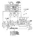
図1は、本発明が適用されたハイブリッド車両8(車両8)の車両用駆動装置10を説明する概略構成図である。車両用駆動装置10は、エンジン24と、動力伝達装置12と、エンジン24と動力伝達装置12との間に設けられている後述するダンパ装置38とを含んで構成されている。図1において、この車両用駆動装置10では、車両8において、主駆動源であるエンジン24のトルクが後述するダンパ装置38および遊星歯車装置26を介して車輪側出力軸14に伝達され、その車輪側出力軸14から差動歯車装置16を介して左右一対の駆動輪18にトルクが伝達されるようになっている。また、この車両用駆動装置10には、走行のための駆動力を出力する力行制御およびエネルギを回収するための回生制御を選択的に実行可能な第2電動機MG2が設けられており、この第2電動機MG2は自動変速機22を介して上記車輪側出力軸に連結されている。したがって、第2電動機MG2から車輪側出力軸へ伝達される出力トルクがその自動変速機22で設定される変速比γs(=第2電動機MG2の回転速度Nmg2/車輪側出力軸の回転速度Nout)に応じて増減されるようになっている。
FIG. 1 is a schematic configuration diagram illustrating a
第2電動機MG2と駆動輪18との間の動力伝達経路に介装されている自動変速機22は、変速比γsが「1」より大きい複数段を成立させることができるように構成されており、第2電動機MG2からトルクを出力する力行時にはそのトルクを増大させて車輪側出力軸へ伝達することができるので、第2電動機MG2が一層低容量もしくは小型に構成される。これにより、例えば高車速に伴って車輪側出力軸の回転速度Noutが増大した場合には、第2電動機MG2の運転効率を良好な状態に維持するために、変速比γsを小さくして第2電動機MG2の回転速度(以下、第2電動機回転速度という)Nmg2を低下させたり、また車輪側出力軸の回転速度Noutが低下した場合には、変速比γsを大きくして第2電動機回転速度Nmg2を増大させる。
The
上記動力伝達装置12は、第1電動機MG1および第2電動機MG2を備えて構成されており、エンジン24のトルクを駆動輪18に伝達する。上記エンジン24は、ガソリンエンジンやディーゼルエンジンなどの燃料を燃焼させて動力を出力する公知の内燃機関であって、マイクロコンピュータを主体とする図示しないエンジン制御用の電子制御装置100(E−ECU)によって、スロットル弁開度や吸入空気量、燃料供給量、点火時期などの運転状態が電気的に制御されるように構成されている。また、エンジン24は、可変バルブ機構25を備えており、エンジン24のバルブタイミングおよびバルブリフト量を適宜調整することができる。
The
前記電子制御装置100(制御装置)には、アクセル操作量センサASからのアクセルペダルの操作量であるアクセル開度Accを表す信号、ブレーキセンサBSからのブレーキペダルの有無Bonを表す信号、クランク角センサ43からのクランク軸36のクランク角に対応するエンジン回転速度Neを表す信号、第1レゾルバ44からの第1電動機MG1の第1電動機回転速度Nmg1を表す信号、第2レゾルバ46からの第2電動機MG2の第2電動機回転速度Nmg2を表す信号、出力軸回転速度センサ48からの車速Vに対応する車輪側出力軸14の回転速度Noutを表す信号、エンジン水温センサ49からのエンジン水温Twを表す信号、バッテリセンサ50からの蓄電装置32(バッテリ)の充電容量SOCを表す信号等が供給されている。
The electronic control device 100 (control device) includes a signal indicating an accelerator opening Acc that is an operation amount of the accelerator pedal from the accelerator operation amount sensor AS, a signal indicating presence / absence Bon of the brake pedal from the brake sensor BS, and a crank angle. A signal representing the engine rotational speed Ne corresponding to the crank angle of the
上記第1電動機MG1(電動機)は、例えば同期電動機であって、駆動トルクTm1を発生させる電動機としての機能と発電機としての機能とを選択的に生じるように構成され、インバータ30を介してバッテリー、コンデンサなどの蓄電装置32に接続されている。そして、マイクロコンピュータを主体とする図示しないモータジェネレータ制御用の電子制御装置100(MG−ECU)によってそのインバータ30が制御されることにより、第1電動機MG1の出力トルクTm1あるいは回生トルクTm1が調節或いは設定されるようになっている。この第1電動機MG1を制御することにより、遊星歯車装置26の差動状態を制御してエンジン回転速度Neを制御することができる。なお、第1電動機MG1が、本発明の電動機に対応している。
The first electric motor MG1 (electric motor) is, for example, a synchronous motor, and is configured to selectively generate a function as a motor for generating a driving torque Tm1 and a function as a generator, and a battery via an
遊星歯車装置26は、サンギヤS0と、そのサンギヤS0に対して同心円上に配置されたリングギヤR0と、これらサンギヤS0およびリングギヤR0に噛み合うピニオンギヤP0を自転かつ公転自在に支持するキャリヤCA0とを三つの回転要素として備えて公知の差動作用を生じるシングルピニオン型の遊星歯車機構である。遊星歯車装置26はエンジン24および自動変速機22と同心に設けられている。遊星歯車装置26および自動変速機22は中心線に対して対称的に構成されているため、図1ではそれらの下半分が省略されている。
The
本実施例では、エンジン24のクランク軸36は、ダンパ装置38および動力伝達軸39を介して遊星歯車装置26のキャリヤCA0に連結されている。これに対してサンギヤS0には第1電動機MG1が連結され、リングギヤR0には車輪側出力軸14および差動歯車装置16を介して駆動輪18が連結されている。このキャリヤCA0は入力要素として機能し、サンギヤS0は反力要素として機能し、リングギヤR0は出力要素として機能している。なお、遊星歯車装置26が本発明の差動機構に対応し、サンギヤS0が本発明の第1回転要素に対応し、キャリヤCA0が本発明の第2回転要素に対応し、リングギヤR0が本発明の第3回転要素に対応している。
In the present embodiment, the
上記遊星歯車装置26において、キャリヤCA0に入力されるエンジン24の出力トルクに対して、第1電動機MG1による反力トルクTm1がサンギヤS0に入力されると、出力要素となっているリングギヤR0には、直達トルクが現れるので、第1電動機MG1は発電機として機能する。また、リングギヤR0の回転速度すなわち車輪側出力軸14の回転速度(出力軸回転速度)Noutが一定であるとき、第1電動機MG1の回転速度Nmg1を上下に変化させることにより、エンジン24の回転速度(エンジン回転速度)Neを連続的に(無段階に)変化させることができる。
In the
本実施例の前記自動変速機22は、一組のラビニョ型遊星歯車機構によって構成されている。すなわち自動変速機22では、第1サンギヤS1と第2サンギヤS2とが設けられており、その第1サンギヤS1にステップドピニオンP1の大径部が噛合するとともに、そのステップドピニオンP1の小径部がピニオンP2に噛合し、そのピニオンP2が前記各サンギヤS1、S2と同心に配置されたリングギヤR1(R2)に噛合している。上記各ピニオンP1、P2は、共通のキャリヤCA1(CA2)によって自転かつ公転自在にそれぞれ保持されている。また、第2サンギヤS2がピニオンP2に噛合している。
The
前記第2電動機MG2(電動機)は、前記モータジェネレータ制御用の電子制御装置100(MG−ECU)によりインバータ40を介して制御されることにより、電動機または発電機として機能させられ、アシスト用出力トルクあるいは回生トルクが調節或いは設定される。第2サンギヤS2にはその第2電動機MG2が連結され、上記キャリヤCA1が車輪側出力軸に連結されている。第1サンギヤS1とリングギヤR1とは、各ピニオンP1、P2と共にタプルピニオン型遊星歯車装置に相当する機構を構成し、また第2サンギヤS2とリングギヤR1とは、ピニオンP2と共にシングルピニオン型遊星歯車装置に相当する機構を構成している。
The second electric motor MG2 (electric motor) is controlled via the
そして、自動変速機22には、第1サンギヤS1を選択的に固定するためにその第1サンギヤS1と非回転部材であるハウジング42との間に設けられた第1ブレーキB1と、リングギヤR1を選択的に固定するためにそのリングギヤR1とハウジング42との間に設けられた第2ブレーキB2とが設けられている。これらのブレーキB1、B2は摩擦力によって制動力を生じるいわゆる摩擦係合装置であり、多板形式の係合装置あるいはバンド形式の係合装置を採用することができる。そして、これらのブレーキB1、B2は、それぞれ油圧シリンダ等のブレーキB1用油圧アクチュエータ、ブレーキB2用油圧アクチュエータにより発生させられる係合圧に応じてそのトルク容量が連続的に変化するように構成されている。
The
以上のように構成された自動変速機22は、第2サンギヤS2が入力要素として機能し、またキャリヤCA1が出力要素として機能し、第1ブレーキB1が係合させられると「1」より大きい変速比γshの高速段Hが成立させられ、第1ブレーキB1に替えて第2ブレーキB2が係合させられるとその高速段Hの変速比γshより大きい変速比γslの低速段Lが成立させられるように構成されている。すなわち、自動変速機22は2段変速機で、これらの変速段HおよびLの間での変速は、車速Vや要求駆動力(もしくはアクセル操作量)などの走行状態に基づいて実行される。より具体的には、変速段領域を予めマップ(変速線図)として定めておき、検出された運転状態に応じていずれかの変速段を設定するように制御される。
In the
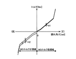
本実施例のダンパ装置38は、エンジン24と第1電動機MG1との間の動力伝達経路上に介挿されており、捩れ角の正負で異なるヒステリシストルクを発生させる図示しない正負可変ヒス機構を備えている。図2に、本実施例のダンパ装置38の捩り特性を示す。図2において、横軸がダンパ装置38の捩れ角θ(rad)を示し、縦軸がトルク(Nm)を示している。図2に示すように、捩れ角θが正方向(正側)の捩れ角領域、すなわちエンジン側からトルク(駆動力)が伝達される領域では、小ヒステリシストルクH1が発生する。一方、捩れ角θが負側の捩れ角領域、すなわち第1電動機側からエンジン側にトルクが伝達される領域では、大ヒステリシストルクH2が発生する。このように、エンジン24によって捩られるダンパ装置38の正方向(正側)の捩れで発生する小ヒステリシストルクH1よりも、第1電動機MG1によって捩られるダンパ装置38の負方向の捩れで発生する大ヒステリシストルクH2の方が大きくなるように設定されている。なお、上記捩れ角θの正負で異なるヒステリシストルクを発生させる、正負可変ヒス機構は公知技術であるので、構造などの具体的な説明については省略する。
The
このように構成されるダンパ装置38において、例えばエンジン始動にあっては、エンジン回転速度Neが第1電動機MG1によって引き上げられるため、ダンパ装置38は負の捩れ角となる。従って、大ヒステリシストルクH2が発生し、エンジン回転速度Neが共振周波数領域を通過する際の捩れ共振が減衰される。また、エンジン駆動中は、小ヒステリシストルクH1が発生するため、動力伝達装置12で発生するこもり音や歯打ち音が抑制される。ここで、エンジンブレーキ走行中(モータリング走行中)においては、エンジン回転速度Neが第1電動機MG1によって制御される。このエンジンブレーキ走行中においてもこもり音や歯打ち音が発生し、このこもり音や歯打ち音を抑制するには、小ヒステリシストルクを発生させることが好ましい。しかしながら、エンジンブレーキ走行中のダンパ装置38は、第1電動機MG1によって捩られる状態となるために負の捩れ角となり、大ヒステリシストルクH2が発生する。従って、こもり音や歯打ち音を効果的に抑制できずNV特性が悪化するという問題があった。
In the
これに対して、このNV特性の悪化する回転速度領域(以下、NV悪化回転速度領域)のエンジン回転速度域を第1電動機MG1によって速やかに通過させてNV特性の悪化を防止する方法がある。しかしながら、例えばエンジン回転速度Neや車速Vが高い状態で第1電動機MG1によるエンジン回転速度Neの引き下げを開始すると、ピニオンギヤP0の回転速度が高回転化されてピニオンギヤの耐久性が低下する可能性が生じる。これを防止するため、ピニオンギヤP0の耐久性が低下しないように、ピニオンギヤP0の上限回転速度Npin_maxが予め定格的に設定される。このピニオンギヤP0に上限回転速度Npin_maxが設定されると、NV悪化回転速度領域においてエンジン回転速度Neを速やかに低下させることが困難となるため、こもり音や歯打ち音が発生しNV特性が悪化する可能性があった。そこで、電子制御装置100は、エンジンブレーキ走行中(モータリング走行中)にエンジン回転速度NeをNV悪化回転速度領域よりも低い回転速度まで引き下げる場合、エンジン回転速度NeをNV悪化回転速度領域よりも高い回転速度で所定の待機時間だけ維持した後にエンジン回転速度Neを低下させる。以下、本願発明に係る電子制御装置100の制御作動について詳細に説明する。 On the other hand, there is a method for preventing the deterioration of the NV characteristics by causing the first electric motor MG1 to quickly pass through the engine rotation speed region in the rotation speed region where the NV characteristics are deteriorated (hereinafter referred to as the NV deterioration rotation speed region). However, for example, if the reduction of the engine rotation speed Ne by the first electric motor MG1 is started with the engine rotation speed Ne and the vehicle speed V being high, the rotation speed of the pinion gear P0 may be increased and the durability of the pinion gear may be reduced. Arise. In order to prevent this, the upper limit rotation speed Npin_max of the pinion gear P0 is preset in advance so that the durability of the pinion gear P0 does not deteriorate. When the upper limit rotation speed Npin_max is set for the pinion gear P0, it is difficult to quickly decrease the engine rotation speed Ne in the NV deterioration rotation speed region, so that a booming noise and a rattling sound are generated and the NV characteristics are deteriorated. There was a possibility. Therefore, when the electronic control unit 100 reduces the engine rotation speed Ne to a rotation speed lower than the NV deterioration rotation speed region during engine braking (motoring driving), the electronic control device 100 decreases the engine rotation speed Ne from the NV deterioration rotation speed region. After maintaining for a predetermined waiting time at a high rotational speed, the engine rotational speed Ne is decreased. Hereinafter, the control operation of the electronic control device 100 according to the present invention will be described in detail.
図1に戻り、電子制御装置100は、モータリング判定部102、目標エンジン回転決定部104、バルブ制御部106、およびモータリング制御部108を機能的に備えている。モータリング判定部102は、エンジン24がモータリング状態、すなわちエンジンブレーキ走行状態でエンジン回転速度Neが第1電動機MG1によって制御される走行状態であるか否かを判定する。モータリング判定部102は、例えばアクセルペダルの踏み込みが解除された状態であることや車速Vなどに基づいてエンジン24がモータリング状態であることを判定する。
Returning to FIG. 1, the electronic control unit 100 functionally includes a motoring determination unit 102, a target engine
モータリング判定部102によってエンジン12がモータリング状態であると判定されると、目標エンジン回転決定部104が実行される。目標エンジン回転決定部104は、モータリング走行中(エンジンブレーキ走行中)において維持するエンジン12の目標回転速度Ne*を決定する。目標エンジン回転決定部104は、車速Vおよび予め設定されているピニオンギヤP0の上限回転速度Npin_maxなどから、ピニオンギヤP0のピニオン回転速度Npinが上限回転速度Npin_max以下となる第1エンジン回転速度Ne1を算出する。なお、サンギヤS0の回転速度Ns(第1電動機回転速度Nmg1)、リングギヤR0の回転速度Nr(車輪側出力軸14の回転速度Nout)、キャリヤCA0の回転速度Nca(エンジン回転速度Ne)、遊星歯車装置26のギヤ比ρ等からなる、ピニオンギヤP0のピニオン回転速度Npinを算出する公知の算術式に基づいて、第1エンジン回転速度Ne1を算出することができる。
When the motoring determination unit 102 determines that the
次いで、目標エンジン回転決定部104は、算出された第1エンジン回転速度Ne1が、予め求められて記憶されているNV特性の悪化するNV悪化回転速度領域(N1_L〜N1_U)にあるか否かを判定する。そして、第1エンジン回転速度Ne1がNV悪化エンジン回転速度領域にある場合(N1_L<Ne1<N1_U)には、NV特性の悪化を回避するため、NV悪化上限回転速度N1_Uを目標回転速度Ne*に決定する。また、第1エンジン回転速度Ne1がNV悪化回転速度領域にない場合には、その回転速度で維持されてもNV特性は悪化しないので、第1エンジン回転速度Ne1を目標回転速度Ne*に決定する。なお、NV悪化回転速度領域が本発明の共振回転数領域に対応している。
Next, the target engine
このNV悪化回転速度領域(N1_L〜N1_U)は、車両用駆動装置10の構造やエンジン水温Tw等に基づいて決定され、例えば自動変速機22のギヤ段やエンジン水温Tw等で規定されるNV悪化領域マップとして記憶されている。また、エンジン24は、例えば油圧を制御することで、バルブの開閉タイミングやバルブリフト量を調整する可変バルブ機構25を備えており、モータリング走行中において例えばバルブの閉じタイミングを遅らせることで、エンジン24の気筒内の圧力を減少させるデコンプ(デコンプ制御、減圧制御)を実施することができる。なお、可変バルブ機構25は、公知の技術であるためその説明を省略する。このデコンプが実行されると、エンジンブレーキ走行中の走行抵抗(エンジンブレーキ力)が小さくなることに関連して、NV悪化回転速度領域が狭くなる。従って、デコンプ制御を実施する場合のNV悪化回転速度領域マップと、デコンプ制御を実施しない場合のNV悪化回転速度領域マップとを別個に備えている。なお、以下において、回転速度(N1_L〜N1_U)をデコンプ制御を実施する場合のNV悪化回転速度領域と定義し、回転速度領域(N2_L〜N2_U)をデコンプ制御を実施しない場合のNV悪化回転速度領域と定義する。また、バルブタイミングだけでなくバルブリフト量を調整することでも気筒内の圧力を減圧することができる。従って、デコンプは、バルブタイミングおよびバルブリフト量の少なくとも1つが実施できるものであれば構わない。
This NV worsening rotational speed region (N1_L to N1_U) is determined based on the structure of the
バルブ制御部106は、エンジンブレーキ走行中における可変バルブ機構25のバルブタイミングおよびバルブリフト量の少なくとも一方を最適に調整する。バルブ制御部106は、予め設定されているバルブタイミングのタイミングマップ、もしくはバルブリフト量のバルブリフト量マップに基づいてバルブタイミングやバルブリフト量を制御する。このタイミングマップおよびバルブリフト量マップは、例えばエンジン回転速度NeやエンジントルクTeなどをパラメータとするマップであり、デコンプを実行する場合には、バルブタイミングやバルブリフト量を調整することで、エンジン24の気筒内の圧力が減圧されて、NV悪化回転速度領域が狭められる。
The
モータリング制御部108は、エンジンブレーキ走行中のエンジン回転速度Neが、前記目標エンジン回転決定部104によって決定された目標回転速度Ne*となるように第1電動機MG1によって制御し、エンジン回転速度Neが目標回転速度Ne*となると、所定の待機時間Tだけその目標回転速度Ne*で維持する。そして、所定の待機時間Tが経過すると、モータリング制御部108は、第1電動機MG1を制御して、NV悪化回転速度領域をエンジン回転速度Neが速やかに通過するように制御する。
The
ここで、所定の待機時間Tは、その待機時間経過した後に第1電動機MG1によってエンジン回転速度NeをNV悪化回転速度領域の下限速度N1_Lまで引き下げても、ピニオン回転速度Npinの上限回転速度Npin_maxに到達しない時間に設定されている。モータリング制御部108は、エンジン回転速度Neを下限速度N1_Lまで低下させたときに、ピニオン回転速度Npinが上限回転速度Npin_max以下となる車速V1を算出し、車速Vがその車速V1以下となると、第1電動機MG1によるエンジン回転速度Neを開始する。従って、モータリング開始(エンブレ開始)時点でのピニオン回転速度Npinおよび車速Vが高いほど、低い場合に比べてエンジン回転速度Neを目標回転速度Ne*で維持する待機時間Tが長くなる。待機時間Tが長くなれば、待機時間経過後の車速Vも低下しているためにピニオン回転速度Npinも低下しており、エンジン回転速度Neを第1電動機MG1によって低下させたときに、ピニオン回転速度Npinを上限回転速度Npin_max以下とすることができる。
Here, the predetermined standby time T is equal to the upper limit rotational speed Npin_max of the pinion rotational speed Npin even if the engine speed Ne is lowered to the lower limit speed N1_L of the NV worsening rotational speed region by the first electric motor MG1 after the standby time has elapsed. It is set to a non-reachable time. When the
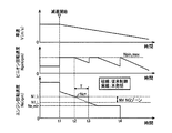
図3は、モータリング制御実行中の作動状態を示すタイムチャートである。図3において、横軸は経過時間を示し、縦軸が上から順番に、車速V(m/s)、ピニオン回転速度Npin(rpm)、およびエンジン回転速度Ne(rpm)をそれぞれ示している。t1時点において減速が開始されると、目標エンジン回転決定部104によって、エンジン回転速度Neの目標回転速度Ne*が決定され、エンジン回転速度Neがその目標回転速度Ne*となるようにモータリング制御部108によって制御される。このとき、バルブ制御部106も併せて実行されることで、NV悪化回転速度領域が適宜調整される。なお、図6においては、NV悪化上限回転速度N1_Uが目標回転速度Ne*に設定されている。
FIG. 3 is a time chart showing an operating state during execution of motoring control. In FIG. 3, the horizontal axis indicates the elapsed time, and the vertical axis indicates the vehicle speed V (m / s), the pinion rotational speed Npin (rpm), and the engine rotational speed Ne (rpm) in order from the top. When deceleration is started at time t1, the target engine
t1時点直後においては、ピニオン回転速度Npinが上限回転速度Npin_maxとなるまで、エンジン回転速度Neが第1電動機MG1によって急激に引き下げられている。そして、ピニオン回転速度Npinが上限回転速度Npin_maxの状態で維持されるようにエンジン回転速度Neが制御されている。t2時点において、エンジン回転速度NeがNV悪化回転速度領域の上限値であるNV悪化上限回転速度N1_Uに到達すると、エンジン回転速度NeがそのNV悪化上限回転速度N1_Uで待機時間Tだけ維持される。これより、エンジン回転速度NeがNV悪化回転速度領域を外れるので、こもり音や歯打ち音が抑制される。また、エンジン回転速度NeがそのNV悪化上限回転速度N1_Uで維持される間(t2時点〜t3時点)に車速Vが低下することからピニオン回転速度Npinも低下する。そして、待機時間Tが経過するt3時点において、第1電動機MG1を制御することにより、エンジン回転速度NeがNV悪化回転速度領域を素早く通過しても、ピニオン回転速度Npinが上限回転速度Npin_max以下となる。また、t3時点以降にあっては、エンジン回転速度NeがNV悪化回転速度領域よりも低下し、予め設定されているエンジン24のモータリング最低回転速度Ne_minで一時的に保持された後、t4時点においてエンジン24が停止されている。
Immediately after time t1, the engine speed Ne is rapidly reduced by the first electric motor MG1 until the pinion speed Npin reaches the upper limit speed Npin_max. The engine rotation speed Ne is controlled so that the pinion rotation speed Npin is maintained at the upper limit rotation speed Npin_max. When the engine rotation speed Ne reaches the NV deterioration upper limit rotation speed N1_U that is the upper limit value of the NV deterioration rotation speed region at time t2, the engine rotation speed Ne is maintained at the NV deterioration upper limit rotation speed N1_U for the waiting time T. As a result, the engine rotational speed Ne deviates from the NV worsening rotational speed region, so that the muffled noise and rattling noise are suppressed. Further, since the vehicle speed V decreases while the engine rotation speed Ne is maintained at the NV deterioration upper limit rotation speed N1_U (from time t2 to time t3), the pinion rotation speed Npin also decreases. At time t3 when the standby time T elapses, the first motor MG1 is controlled so that the pinion rotational speed Npin is equal to or lower than the upper limit rotational speed Npin_max even if the engine rotational speed Ne passes through the NV deterioration rotational speed region quickly. Become. Further, after the time point t3, the engine speed Ne falls below the NV deterioration speed range and is temporarily held at the preset minimum motoring speed Ne_min of the
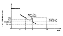
図4は、モータリング制御部108の他の態様である。例えば、エンジン24を停止させる際、t2時点においてエンジン回転速度Neを目標回転速度Ne*(N2_U)に制御すると、一点鎖線で示すように、エンジン回転速度Neを目標回転速度Ne*のままで維持し、エンジン回転速度Neを零回転まで低下させることができる車速Vとなると、t4時点においてエンジン24を停止させる。このように制御することで、エンジン回転速度Neを第1電動機MG1によって高い回転速度で長時間維持する分だけ燃費が低下するものの、エンジン回転速度Neの勾配変化が低減されるので、NV特性がさらに向上する。特に、NV悪化回転速度領域とモータリング最低回転速度Ne_minとが近い場合において、燃費悪化が顕著とならないため好適に実行される。
FIG. 4 shows another aspect of the
また、二点鎖線は、前記バルブ制御部106によるデコンプを実行した場合の態様である。デコンプが実行されない場合には、NV悪化回転速度領域がN2_L〜N2_Uの間となる。これに対して、デコンプが実施されると、NV悪化回転速度領域がN1_L(=N2_L)〜N1_Uの間となり、NV悪化回転速度領域が狭められている。これより、エンジン回転速度Neの目標回転速度Ne*がデコンプしない場合に比べて低回転速度となり、これに起因するエンジンブレーキ力の低下分だけ第1電動機MG1の回生量を増加することができるため燃費が向上する。また、NV悪化回転速度領域が狭められることで、第1電動機MGによってエンジン回転速度Neを目標回転速度Ne*に維持する待機時間T(頻度)も低減される。
A two-dot chain line is a mode when decompression by the
図5は、電子制御装置100の制御作動の要部、すなわちモータリング走行中のNV特性の悪化を防止できる制御作動を説明するフローチャートである。このフローチャートは、例えば数msec乃至数十msec程度の極めて短いサイクルタイムで繰り返し実行される。 FIG. 5 is a flowchart for explaining a main part of the control operation of the electronic control unit 100, that is, a control operation that can prevent the deterioration of the NV characteristic during the motoring travel. This flowchart is repeatedly executed with an extremely short cycle time of, for example, about several milliseconds to several tens of milliseconds.
先ず、モータリング判定部102に対応するステップS1(以下、ステップを省略する)において、モータリング走行中(エンジンブレーキ走行中)であるか否かが判定される。S1が否定される場合、本ルーチンは終了させられる。S1が肯定される場合、目標エンジン回転決定部104に対応するS2において、ピニオン回転速度Npinが上限回転速度Npin_max以下となる第1エンジン回転速度Ne1が算出される。目標エンジン回転速度104に対応するS3では、S2で算出された第1エンジン回転速度Ne1が、NV悪化回転速度領域にある(N1_L<Ne1<N1_U)か否かが判定される。
First, in step S1 (hereinafter, step is omitted) corresponding to the motoring determination unit 102, it is determined whether or not the motoring traveling (engine braking traveling) is being performed. If S1 is negative, the routine is terminated. When S1 is affirmed, in S2 corresponding to the target engine
S3が否定される場合、目標エンジン回転速度104およびバルブ制御部106に対応するS5において、第1エンジン回転速度Ne1がNV悪化回転速度領域(N1_L〜N1_U)にないため、その第1エンジン回転速度Ne1が目標回転速度Ne*に決定される。そして、モータリング制御部108によって、エンジン回転速度Neが目標回転速度Ne*(=Ne1)に制御され、所定の待機時間Tだけその回転速度Ne1で維持した後に、NV悪化回転速度領域を速やかに通過させる。これより、エンジン回転速度NeがNV悪化回転速度領域に滞留する時間が短くなるため、NV特性が向上する。これと併行して、エンジン24のバルブタイミングやバルブリフト量が適宜調整されることで、エンジン24の気筒内の圧力がデコンプ(減圧)される。従って、NV悪化回転領域が回転速度領域(N2_L〜N2_U)から回転速度領域(N1_L〜N1_U)に狭められる。
When S3 is negative, since the first engine speed Ne1 is not in the NV deterioration speed range (N1_L to N1_U) in S5 corresponding to the
S3が肯定される場合、目標エンジン回転速度104およびバルブ制御部106に対応するS4において、第1エンジン回転速度Ne1がNV悪化回転速度領域にある(N1_L<Ne1<N1_U)ので、NV悪化上限回転速度N1_Uが目標回転速度Ne*に決定される。そして、モータリング制御部108によって、エンジン回転速度Neが目標エンジン回転速度Ne*(N1_U)に制御され、所定の待機時間Tで維持した後に、NV悪化回転速度領域を速やかに通過させる。これより、エンジン回転速度NeがNV悪化回転速度領域に滞留する時間が短くなるため、NV特性が向上する。これと併行して、エンジン24のバルブタイミングやバルブリフト量が適宜調整されることで、エンジン24の気筒内の圧力がデコンプ(減圧)される。従って、NV悪化回転領域が回転速度領域(N2_L〜N2_U)から回転速度領域(N1_L〜N1_U)に狭められる。
When S3 is affirmed, in S4 corresponding to the
上述のように、本実施例によれば、モータリング走行中(エンジンブレーキ走行中)にエンジン回転速度NeをNV悪化回転速度領域よりも低い回転速度に制御する際、エンジン回転速度NeをNV悪化回転速度領域より高い回転速度で維持することで、エンジン24のNV悪化回転速度領域での滞留を回避する。また、このエンジン回転速度NeをNV悪化回転速度領域より高い回転速度で維持する間に車速Vが低下するため、遊星歯車装置26のピニオン回転速度Npinも低下する。そして、エンジン回転速度Neを速やかに低下させることができるまで、遊星歯車装置26のピニオン回転速度Npinおよび車速Vが低下すると、第1電動機MG1によってエンジン回転速度Neを速やかに低下させて、NV特性の悪化を回避することができる。
As described above, according to this embodiment, when the engine rotation speed Ne is controlled to a lower rotation speed than the NV worsening rotation speed region during motoring running (engine braking running), the engine rotation speed Ne is worsened by NV. By maintaining at a higher rotational speed than the rotational speed region, stagnation of the
また、本実施例によれば、エンジン回転速度NeをNV悪化回転速度領域よりも低い回転速度まで低下させる際、ピニオンギヤP0のピニオン回転速度Npinが高いほど、低い場合に比べてNV悪化回転速度領域よりも高い回転速度で維持する待機時間Tが長い。このようにすれば、ピニオンギヤP0のピニオン回転速度Npinが高いほど低い場合に比べてNV悪化回転速度領域よりも高い回転速度で維持する待機時間Tが長くなるため、車速Vの低下とともにピニオンギヤP0のピニオン回転速度Npinが低下する。従って、ピニオンギヤP0のピニオン回転速度Npinが高い場合であっても、ピニオンギヤP0のピニオン回転速度Npinが低下した時点で第1電動機MG1によるエンジン回転速度Neの低下が開始されるので、NV悪化回転速度領域の滞留時間が短くなり、NV特性の悪化が回避される。一方、ピニオン回転速度Npinが低い場合には、エンジン回転速度NeをNV悪化回転速度領域よりも高い回転速度で維持する時間も短くなるので、エンジン回転速度Neが速やかに低下する。このように、ピニオン回転速度Npinに応じて、エンジン回転速度NeをNV悪化回転速度領域よりも高い回転速度で維持する待機時間Tが最適に調整され、NV特性の悪化を回避しつつエンジン回転速度Neを速やかに低下することができる。 In addition, according to the present embodiment, when the engine speed Ne is decreased to a lower rotational speed than the NV worsening rotational speed region, the higher the pinion rotational speed Npin of the pinion gear P0, the lower the NV worsening rotational speed region. The waiting time T maintained at a higher rotational speed is longer. In this way, the higher the pinion rotational speed Npin of the pinion gear P0, the longer the waiting time T for maintaining the rotational speed higher than the NV worsening rotational speed region as compared with the case where the pinion rotational speed Npin is lower. The pinion rotation speed Npin decreases. Accordingly, even when the pinion rotation speed Npin of the pinion gear P0 is high, the decrease in the engine rotation speed Ne by the first electric motor MG1 starts when the pinion rotation speed Npin of the pinion gear P0 decreases, so the NV deterioration rotation speed. The residence time of the region is shortened, and the deterioration of NV characteristics is avoided. On the other hand, when the pinion rotational speed Npin is low, the time for maintaining the engine rotational speed Ne at a rotational speed higher than the NV deterioration rotational speed region is also shortened, so that the engine rotational speed Ne is rapidly decreased. As described above, the waiting time T for maintaining the engine rotation speed Ne at a higher rotation speed than the NV deterioration rotation speed region is optimally adjusted according to the pinion rotation speed Npin, and the engine rotation speed is avoided while avoiding the deterioration of the NV characteristics. Ne can be quickly reduced.
また、本実施例によれば、エンジン24のバルブタイミングおよびバルブリフト量の少なくとも1つを変更可能な可変バルブ機構25を備えており、そのエンジン24のバルブタイミングおよびバルブリフト量の少なくとも1つを制御することで、NV悪化回転速度領域において、エンジン24の気筒内の圧力を減圧するデコンプが実施される。このようにすれば、NV悪化回転速度領域において気筒内の圧力が減圧されるデコンプが実施されることで、エンジン24の回転抵抗が低減され、NV悪化回転速度領域が狭くなる。従って、目標回転速度Ne*が低下してエンジンブレーキ力が低下する分だけ第1電動機MG1の回生量を増加できるため燃費悪化も抑制される。
Further, according to the present embodiment, the
つぎに、本発明の他の実施例を説明する。なお、以下の説明において前述の実施例と共通する部分には同一の符号を付して説明を省略する。 Next, another embodiment of the present invention will be described. In the following description, parts common to those in the above-described embodiment are denoted by the same reference numerals and description thereof is omitted.
本実施例の車両8では、例えば低速運転中においてエンジン24の始動・停止が繰り返される所謂エンジン間欠運転に起因する駆動力変化を抑制するため、エンジン間欠運転を禁止する制御が実行される。以下、このエンジン間欠運転を禁止する制御を伴うときのモータリング走行中の制御について説明する。
In the
本実施例の目標エンジン回転決定部104は、エンジン24の間欠運転を禁止することを考慮した第2エンジン回転速度Ne2を算出する。目標エンジン回転決定部104は、エンジン24の定格値や蓄電装置32の充電容量SOCなどに基づいて、エンジン24の始動・停止が回避される第2エンジン回転速度Ne2を算出する。そして、目標エンジン回転決定部104は、算出された第2エンジン回転速度Ne2が、NV悪化回転速度領域(N1_L〜N1_U)にあるか否かを判定する。第2エンジン回転速度Ne2がNV特性の悪化する回転速度領域にある場合、NV特性の悪化を回避するため、目標エンジン回転決定部104は、NV悪化上限回転速度N1_Uを目標エンジン回転速度Ne*に決定する。第2エンジン回転速度Ne2がNV特性の悪化する回転速度領域にない場合、目標エンジン回転決定部104は、第2エンジン回転速度Ne2を目標エンジン回転速度Ne*に決定する。
The target engine
図6は、本実施例に対応する電子制御装置100の制御作動の要部、すなわちモータリング走行中のNV特性の悪化を防止できる制御作動を説明するフローチャートである。 FIG. 6 is a flowchart for explaining the main part of the control operation of the electronic control device 100 corresponding to the present embodiment, that is, the control operation that can prevent the deterioration of the NV characteristic during the motoring travel.
先ず、モータリング判定部102に対応するS1において、モータリング走行中であるか否かが判定される。S1が否定される場合、本ルーチンは終了させられる。S1が肯定される場合、目標エンジン回転決定部104に対応するS11において、エンジン間欠運転が回避される第2エンジン回転速度Ne2が算出される。次いで、目標エンジン回転決定部104に対応するS12において、第2エンジン回転速度Ne2がNV悪化回転速度領域にある(N1_L<Ne2<N1_U)か否かが判定される。
First, in S1 corresponding to the motoring determination unit 102, it is determined whether or not the motoring traveling is in progress. If S1 is negative, the routine is terminated. When S1 is affirmed, in S11 corresponding to the target engine
S12が否定される場合、目標エンジン回転決定部104およびバルブ制御部106に対応するS14において、第2エンジン回転速度Ne2がNV特性の悪化する回転速度領域にないため、第2エンジン回転速度Ne2が目標回転速度Ne*に決定される。そして、モータリング制御部108によって、エンジン回転速度Neが目標エンジン回転速度Ne*(=Ne2)に制御され、所定の待機時間Tだけその回転速度Ne2で維持した後に、NV悪化回転速度領域を速やかに通過させる。これより、エンジン回転速度NeがNV悪化回転速度領域に滞留する時間が短くなるため、NV特性が向上する。これと併行して、エンジン24のバブルタイミングやバルブリフト量が適宜調整されることで、エンジン24の圧力がデコンプ(減圧)される。従って、NV悪化回転領域が回転速度領域(N2_L〜N2_U)から回転速度領域(N1_L〜N1_U)に狭められる。特に、NV悪化回転速度領域のみデコンプを実施すれば、急加速時のエンジントルクレスポンスも向上する。
If S12 is negative, the second engine rotational speed Ne2 is not in the rotational speed region in which the NV characteristic deteriorates in S14 corresponding to the target engine
S12が肯定される場合、目標エンジン回転決定部104およびバルブ制御部106に対応するS13において、第2エンジン回転速度Ne2がNV特性の悪化する回転速度領域にあるので、目標エンジン回転速度Ne*がNV悪化上限回転速度N1_Uに決定される。そして、モータリング制御部108によって、エンジン回転速度Neが目標エンジン回転速度Ne*(=N1_U)に制御され、所定の待機時間Tだけその回転速度で維持した後に、NV悪化回転速度領域を速やかに通過させる。これより、エンジン回転速度NeがNV悪化回転速度領域に滞留する時間が短くなるため、NV特性が向上する。これと併行して、エンジン24のバルブタイミングやバルブリフト量が適宜調整されることで、エンジン24の気筒内の圧力がデコンプ(減圧)される。従って、NV悪化回転領域が回転速度領域(N2_L〜N2_U)から回転速度領域(N1_L〜N1_U)に狭められる。
When S12 is affirmed, in S13 corresponding to the target engine
本実施例では、蓄電装置32の充電容量SOCが予め設定されている上限値を超えてしまい、第1電動機MG1の充電制御(回生制御)が制限されている場合においてモータリング制御されるときの制御作動について説明する。
In the present embodiment, when the charging capacity SOC of the
本実施例の目標エンジン回転決定部104は、蓄電装置32の充電が制限されている場合において、バッテリ放電要求量や要求制動力などに基づいて算出される第3エンジン回転速度Ne3を算出する。この第3エンジン回転速度Ne3は、第1電動機MG1によってその回転速度Ne3に制御することで要求される電力が放電され、且つ、要求される制動力(エンジンブレーキ力)が得られる回転速度となる。エンジン回転速度Neが高くなると、その回転速度に維持するために第1電動機MG1が消費する電力も増加し、エンジンブレーキ力も大きくなる。従って、第3エンジン回転速度Ne3がNV悪化上限回転速度N2_Uよりも高い回転速度となることで、蓄電装置32の放電および高いエンジンブレーキ力が確保される。なお、バッテリ放電要求量は、例えば現時点の充電容量SOCと予め設定されている許容充電容量との差分等に基づいて算出され、要求制動力は、例えばブレーキペダルの踏み込み量などに基づいて算出される。
The target engine
そして、目標エンジン回転決定部104は、算出された第3エンジン回転速度Ne3が、NV悪化回転速度領域(N2_L〜N2_U)のNV悪化上限回転速度N2_Uよりも低いか否かを判定する。第3エンジン回転速度Ne3がNV悪化上限回転速度N2_Uよりも低い場合、エンジン24がNV特性の悪化するNV悪化上限回転速度N2_U以下の回転速度領域で作動しないように、目標エンジン回転決定部104は、上限回転速度N2_Uを目標エンジン回転速度Ne*に決定する。第3エンジン回転速度Ne3が上限回転速度N2_U以上である場合、目標エンジン回転決定部104は、第3エンジン回転速度Ne3を目標エンジン回転速度Ne*に決定する。
Then, the target engine
ここで、本実施例では、基本的にはデコンプは実施されず、NV悪化回転速度領域(N2_L〜N2_U)は、デコンプ制御を実施しないことを前提とする回転速度(N2_L〜N2_U)となる。本実施例のように蓄電装置32の充電が制限されている場合、第1電動機MG1の回生(発電)による制動力が得られないため、その分だけ要求されるエンジンブレーキ力も大きくなる。これに対して、デコンプが実施されると、エンジン24の回転抵抗力が小さくなって得られるエンジンブレーキ力が小さくなってしまう。従って、蓄電装置32の充電が制限されている場合には、基本的にはデコンプは実施されず、デコンプが実施されないことを前提としたNV悪化回転速度領域(N2_L〜N2_U)に基づいて、第3エンジン回転速度Ne3がNV悪化回転速度領域にあるか否かが判定される。
Here, in the present embodiment, basically, decompression is not performed, and the NV deterioration rotational speed region (N2_L to N2_U) becomes a rotational speed (N2_L to N2_U) on the premise that decompression control is not performed. When charging of the
図7は、本実施例に対応する電子制御装置100の制御作動の要部、すなわちモータリング走行中のNV特性の悪化を防止できる制御作動を説明するフローチャートである。 FIG. 7 is a flowchart for explaining a main part of the control operation of the electronic control device 100 corresponding to the present embodiment, that is, a control operation that can prevent deterioration of the NV characteristic during motoring traveling.
先ず、モータリング判定部102に対応するS1において、モータリング走行中であるか否かが判定される。S1が否定される場合、本ルーチンは終了させられる。S1が肯定される場合、目標エンジン回転決定部104に対応するS21において、バッテリ放電要求量、および要求制動力などに基づいて、第3エンジン回転速度Ne3が算出される。次いで、目標エンジン回転決定部104に対応するS22において、第3エンジン回転速度Ne3が上限回転速度N2_Uよりも低いか否かが判定される。
First, in S1 corresponding to the motoring determination unit 102, it is determined whether or not the motoring traveling is in progress. If S1 is negative, the routine is terminated. When S1 is affirmed, in S21 corresponding to the target engine
S22が否定される場合、目標エンジン回転決定部104およびバルブ制御部106に対応するS24において、第3エンジン回転速度Ne3がNV特性の悪化する回転速度領域にないため、第3エンジン回転速度Ne3が目標回転速度Ne*に決定される。そして、モータリング制御部108によって、エンジン回転速度Neが目標回転速度Ne*(=Ne3)に制御され、所定の待機時間Tだけその回転速度で維持した後に、NV悪化回転速度領域を速やかに通過させる。これより、エンジン回転速度NeがNV悪化回転速度領域に滞留する時間が短くなるため、NV特性が向上する。これと併行して、デコンプを実施しないようにエンジン24のバルブタイミングやバルブリフト量が適宜調整される。
If S22 is negative, since the third engine speed Ne3 is not in the rotational speed region where the NV characteristic deteriorates in S24 corresponding to the target engine
S22が肯定される場合、目標エンジン回転決定部104およびバルブ制御部106に対応するS23において、第3エンジン回転速度Ne3が上限回転速度N2_Uよりも低い回転速度にあるので、NV特性の悪化を回避するため、上限回転速度N2_Uが目標回転速度Ne*に決定される。そして、モータリング制御部108によって、エンジン回転速度Neが上限回転速度N2_Uに制御され、所定の待機時間Tだけその回転速度で維持した後に、NV悪化回転速度領域を速やかに通過させる。これと併行して、デコンプを実施しないようにエンジン24のバルブタイミングやバルブリフト量が適宜調整される。
If S22 is positive, in S23 corresponding to the target engine
上述のように、本実施例によっても、前述した実施例と同様の効果を得ることができる。また、第1電動機MG1と電力の授受を行う蓄電装置32の充電が制限されている場合は、NV悪化回転速度領域よりも高い回転速度でエンジン回転速度Neを維持させた状態とする。このようにすれば、エンジン回転速度NeをNV悪化回転速度領域よりも高い回転速度で維持することで、NV特性の悪化を回避することができる。また、エンジン回転速度NeをNV悪化回転速度領域よりも高い回転速度で維持し続けることで、蓄電装置32の放電を促し、蓄電容量SOCを正常な値に戻すことができる。さらに、エンジン回転速度Neが高くなるので、エンジンブレーキ力も高くなり、所望する制動力を確保することができる。
As described above, this embodiment can provide the same effects as those of the above-described embodiment. When charging of
以上、本発明の実施例を図面に基づいて詳細に説明したが、本発明はその他の態様においても適用される。 As mentioned above, although the Example of this invention was described in detail based on drawing, this invention is applied also in another aspect.
例えば、前述の各実施例は、それぞれ独立して記載されているが、矛盾の生じない範囲で各実施例を適宜組み合わせて実施しても構わない。 For example, each of the above-described embodiments has been described independently. However, the embodiments may be combined as appropriate within a range where no contradiction occurs.
また、前述の実施例では、第1エンジン回転速度Ne1がNV悪化回転速度領域にある場合、目標回転速度Ne*をNV悪化上限回転速度N1_Uとしたが、目標回転速度Ne*はNV悪化上限回転速度N1_Uよりも高い回転速度であれば構わない。また、第2エンジン回転速度Ne2および第3エンジン回転速度Ne3についても同様である。 In the above-described embodiment, when the first engine rotational speed Ne1 is in the NV worsening rotational speed region, the target rotational speed Ne * is set to the NV worsening upper limit rotational speed N1_U, but the target rotational speed Ne * is the NV worsening upper limit rotational speed. Any rotational speed higher than the speed N1_U may be used. The same applies to the second engine speed Ne2 and the third engine speed Ne3.
また、前述の実施例では、差動機構が遊星歯車装置26で構成され、遊星歯車装置26のサンギヤS0(第1回転要素)が第1電動機MG1、キャリヤCA0(第2回転要素)がエンジン24、リングギヤR0(第3回転要素)が駆動輪18にそれぞれ連結されているが、差動機構は遊星歯車装置に限定されず、連結構成についてもこの実施例に限定されず適宜変更しても構わない。
Further, in the above-described embodiment, the differential mechanism is constituted by the
また、前述の実施例では、可変バルブ機構25は、バルブのバルブタイミングおよびバルブリフト量を調整可能に構成され、これらバルブタイミングおよびバルブリフト量を調整することでデコンプされるものであったが、可変バルブ機構25は、バルブタイミングおよびバルブリフト量の何れか一方を調整に可能に構成されていれば足り、これらの一方を制御してデコンプ(減圧)するものであっても構わない。
In the above-described embodiment, the
また、前述の実施例では、エンジン24の気筒内の圧力を減圧するデコンプを実施することで、NVの悪化する回転速度領域を狭めているが、デコンプを必ずしも実施する必要はなく、デコンプを実施しなくとも構わない。
In the above-described embodiment, the decompression for reducing the pressure in the cylinder of the
また、前述の実施例では、第1回転要素であるサンギヤS0が第1電動機MG1に直接連結されているが、歯車やベルト車等を介して動力伝達可能に連結されていても構わない。また、第2回転要素であるキャリヤCA0がダンパ装置38を介してエンジン24に連結されているが、さらに歯車やベルト車等を介して動力伝達可能に連結されていても構わない。また、第3回転要素であるリングギヤR0が差動歯車装置16を介して駆動輪18に連結されているが、さらに歯車やベルト車等を介して動力伝達可能に連結されていても構わない。
In the above-described embodiment, the sun gear S0, which is the first rotating element, is directly connected to the first electric motor MG1, but may be connected so as to be able to transmit power via a gear, a belt wheel, or the like. Further, the carrier CA0 as the second rotating element is connected to the
また、前述の実施例では、エンジン回転速度Neが目標回転速度Ne*で一定値に維持されているが、必ずしも一定値に限定されない。本発明は、エンジンブレーキ走行中のエンジン回転速度Neを、NV悪化回転速度領域よりも高い回転速度で維持するのであれば回転速度変化が生じても許容される。また、NV悪化回転速度領域を通過する際にも、指令値は急降下しているがこの指令値についても所定の勾配があっても構わない。 In the above-described embodiment, the engine rotational speed Ne is maintained at a constant value at the target rotational speed Ne *, but is not necessarily limited to a constant value. In the present invention, if the engine rotational speed Ne during engine braking is maintained at a rotational speed higher than the NV worsening rotational speed region, even if a rotational speed change occurs, it is allowed. Also, when passing through the NV worsening rotation speed region, the command value drops rapidly, but this command value may have a predetermined gradient.
なお、上述したのはあくまでも一実施形態であり、本発明は当業者の知識に基づいて種々の変更、改良を加えた態様で実施することができる。 The above description is only an embodiment, and the present invention can be implemented in variously modified and improved forms based on the knowledge of those skilled in the art.
8:ハイブリッド車両
18:駆動輪
24:エンジン
25:可変バルブ機構
26:遊星歯車装置(差動機構)
32:蓄電装置(バッテリ)
38:ダンパ装置
100:電子制御装置(制御装置)
MG1:第1電動機(電動機)
S0:サンギヤ(第1回転要素)
CA0:キャリヤ(第2回転要素)
R0:リングギヤ(第3回転要素)
P0:ピニオンギヤ
8: Hybrid vehicle 18: Drive wheel 24: Engine 25: Variable valve mechanism 26: Planetary gear unit (differential mechanism)
32: Power storage device (battery)
38: Damper device 100: Electronic control device (control device)
MG1: First motor (motor)
S0: Sun gear (first rotating element)
CA0: carrier (second rotating element)
R0: Ring gear (third rotating element)
P0: Pinion gear
Claims (3)
前記エンジンは、該エンジンのバルブタイミング、および該エンジンのバルブリフト量の少なくとも1つを変更可能な可変バルブ機構を備えており、
エンジンブレーキ走行中に前記エンジン回転速度を共振回転数領域よりも低い回転速度に制御する場合、前記バルブタイミングおよび前記バルブリフト量の少なくとも1つを制御して、前記エンジンの気筒内の圧力を減圧して、前記共振回転数領域を低回転速度側に変更し、該共振回転数領域よりも高い回転速度にエンジン回転速度を維持した後に、該エンジン回転速度を低下させることを特徴とするハイブリッド車両の制御装置。 A differential mechanism comprising a first rotating element connected to the electric motor, a second rotating element connected to the engine, and a third rotating element connected to the drive wheel; and between the engine and the electric motor And a damper device interposed on the power transmission path of the hybrid vehicle, wherein the engine rotation speed of the engine can be controlled by the electric motor,
The engine includes a variable valve mechanism capable of changing at least one of a valve timing of the engine and a valve lift amount of the engine,
When the engine speed is controlled to be lower than the resonance speed range during engine braking , the pressure in the cylinder of the engine is reduced by controlling at least one of the valve timing and the valve lift amount. Then, after changing the resonance rotational speed region to a low rotational speed side and maintaining the engine rotational speed at a rotational speed higher than the resonant rotational speed region, the hybrid vehicle is characterized in that the engine rotational speed is decreased. Control device.
前記エンジン回転速度を、前記共振回転数領域よりも低い回転速度まで低下させる際、前記遊星歯車装置のピニオンギヤの回転速度が高いほど、低い場合に比べて前記共振回転数領域よりも高い回転速度で維持する時間が長いことを特徴とする請求項1のハイブリッド車両の制御装置。 The differential mechanism is composed of a planetary gear device,
When lowering the engine rotation speed to a lower rotation speed than the resonance rotation speed region, the higher the rotation speed of the pinion gear of the planetary gear device, the higher the rotation speed than the resonance rotation speed region compared to the lower case. 2. The control apparatus for a hybrid vehicle according to claim 1, wherein the time for maintaining is long.
Priority Applications (1)
| Application Number | Priority Date | Filing Date | Title |
|---|---|---|---|
| JP2013062842A JP6065693B2 (en) | 2013-03-25 | 2013-03-25 | Control device for hybrid vehicle |
Applications Claiming Priority (1)
| Application Number | Priority Date | Filing Date | Title |
|---|---|---|---|
| JP2013062842A JP6065693B2 (en) | 2013-03-25 | 2013-03-25 | Control device for hybrid vehicle |
Publications (2)
| Publication Number | Publication Date |
|---|---|
| JP2014184940A JP2014184940A (en) | 2014-10-02 |
| JP6065693B2 true JP6065693B2 (en) | 2017-01-25 |
Family
ID=51832892
Family Applications (1)
| Application Number | Title | Priority Date | Filing Date |
|---|---|---|---|
| JP2013062842A Active JP6065693B2 (en) | 2013-03-25 | 2013-03-25 | Control device for hybrid vehicle |
Country Status (1)
| Country | Link |
|---|---|
| JP (1) | JP6065693B2 (en) |
Families Citing this family (1)
| Publication number | Priority date | Publication date | Assignee | Title |
|---|---|---|---|---|
| JP6911713B2 (en) | 2017-11-06 | 2021-07-28 | トヨタ自動車株式会社 | Hybrid car |
Family Cites Families (10)
| Publication number | Priority date | Publication date | Assignee | Title |
|---|---|---|---|---|
| JP2001123857A (en) * | 1996-07-18 | 2001-05-08 | Toyota Motor Corp | Drive device |
| JP2000034913A (en) * | 1998-07-17 | 2000-02-02 | Toyota Motor Corp | Variable valve system for internal combustion engine |
| JP4029581B2 (en) * | 2000-11-15 | 2008-01-09 | トヨタ自動車株式会社 | Internal combustion engine shutdown control device |
| JP4296964B2 (en) * | 2004-02-27 | 2009-07-15 | アイシン・エィ・ダブリュ株式会社 | Vehicle drive control device |
| JP4155244B2 (en) * | 2004-08-05 | 2008-09-24 | トヨタ自動車株式会社 | Control device for vehicle drive device |
| JP2010018212A (en) * | 2008-07-11 | 2010-01-28 | Toyota Motor Corp | Control device of hybrid system |
| JP5434220B2 (en) * | 2009-04-17 | 2014-03-05 | トヨタ自動車株式会社 | Internal combustion engine with variable compression ratio mechanism |
| WO2011070673A1 (en) * | 2009-12-11 | 2011-06-16 | トヨタ自動車株式会社 | Vehicle and control method therefor |
| JP5725037B2 (en) * | 2010-12-24 | 2015-05-27 | トヨタ自動車株式会社 | Vehicle and vehicle control method |
| JP5621761B2 (en) * | 2011-12-12 | 2014-11-12 | トヨタ自動車株式会社 | Vehicle equipped with an internal combustion engine having a variable compression ratio mechanism |
-
2013
- 2013-03-25 JP JP2013062842A patent/JP6065693B2/en active Active
Also Published As
| Publication number | Publication date |
|---|---|
| JP2014184940A (en) | 2014-10-02 |
Similar Documents
| Publication | Publication Date | Title |
|---|---|---|
| JP4241837B2 (en) | Vehicle and control method thereof | |
| JP4501956B2 (en) | Control device for drive device for hybrid vehicle | |
| JP4232824B2 (en) | Hybrid vehicle and control method thereof | |
| JP4201044B2 (en) | Vehicle and control method thereof | |
| JP4890595B2 (en) | Vehicle control device | |
| JP5413547B1 (en) | Control device for hybrid vehicle | |
| JP2009067270A (en) | Controller of vehicle power transmission | |
| JP4380636B2 (en) | Oil pump control device for electric vehicle and electric vehicle equipped with the same | |
| JP2006242096A (en) | Hybrid vehicle and its control method | |
| JPWO2010134165A1 (en) | Control device for vehicle power transmission device | |
| JP6315016B2 (en) | Control device for hybrid vehicle | |
| JP2010100145A (en) | Control device for vehicular power transmission device | |
| JP6583295B2 (en) | Vehicle control device | |
| JP2010264796A (en) | Hybrid vehicle and control method thereof | |
| JP4229046B2 (en) | Control device for vehicle drive device | |
| JP2009143315A (en) | Power output device and vehicle loaded with the same and control method for power output device | |
| JP2005012864A (en) | Controller of hybrid driver | |
| JP6065693B2 (en) | Control device for hybrid vehicle | |
| JP2008184065A (en) | Vehicle and control method thereof | |
| JP4483892B2 (en) | Control device for drive device for hybrid vehicle | |
| JP2009012731A (en) | Controller for power transmission device for hybrid vehicle | |
| JP7215967B2 (en) | Hybrid vehicle control device | |
| JP5838869B2 (en) | Control device for hybrid vehicle | |
| JP2013189048A (en) | Control device of hybrid vehicle | |
| JP2010126094A (en) | Apparatus for controlling power transmission device for vehicle |
Legal Events
| Date | Code | Title | Description |
|---|---|---|---|
| A621 | Written request for application examination |
Free format text: JAPANESE INTERMEDIATE CODE: A621 Effective date: 20150407 |
|
| A977 | Report on retrieval |
Free format text: JAPANESE INTERMEDIATE CODE: A971007 Effective date: 20160329 |
|
| A131 | Notification of reasons for refusal |
Free format text: JAPANESE INTERMEDIATE CODE: A131 Effective date: 20160510 |
|
| A521 | Written amendment |
Free format text: JAPANESE INTERMEDIATE CODE: A523 Effective date: 20160706 |
|
| TRDD | Decision of grant or rejection written | ||
| A01 | Written decision to grant a patent or to grant a registration (utility model) |
Free format text: JAPANESE INTERMEDIATE CODE: A01 Effective date: 20161129 |
|
| A61 | First payment of annual fees (during grant procedure) |
Free format text: JAPANESE INTERMEDIATE CODE: A61 Effective date: 20161212 |
|
| R151 | Written notification of patent or utility model registration |
Ref document number: 6065693 Country of ref document: JP Free format text: JAPANESE INTERMEDIATE CODE: R151 |