JP6062688B2 - Ophthalmic apparatus, method for controlling ophthalmic apparatus, and program - Google Patents
Ophthalmic apparatus, method for controlling ophthalmic apparatus, and program Download PDFInfo
- Publication number
- JP6062688B2 JP6062688B2 JP2012190617A JP2012190617A JP6062688B2 JP 6062688 B2 JP6062688 B2 JP 6062688B2 JP 2012190617 A JP2012190617 A JP 2012190617A JP 2012190617 A JP2012190617 A JP 2012190617A JP 6062688 B2 JP6062688 B2 JP 6062688B2
- Authority
- JP
- Japan
- Prior art keywords
- feature
- fundus
- image
- feature region
- eye
- Prior art date
- Legal status (The legal status is an assumption and is not a legal conclusion. Google has not performed a legal analysis and makes no representation as to the accuracy of the status listed.)
- Active
Links
Images


Classifications
-
- A—HUMAN NECESSITIES
- A61—MEDICAL OR VETERINARY SCIENCE; HYGIENE
- A61B—DIAGNOSIS; SURGERY; IDENTIFICATION
- A61B3/00—Apparatus for testing the eyes; Instruments for examining the eyes
- A61B3/10—Objective types, i.e. instruments for examining the eyes independent of the patients' perceptions or reactions
- A61B3/102—Objective types, i.e. instruments for examining the eyes independent of the patients' perceptions or reactions for optical coherence tomography [OCT]
-
- A—HUMAN NECESSITIES
- A61—MEDICAL OR VETERINARY SCIENCE; HYGIENE
- A61B—DIAGNOSIS; SURGERY; IDENTIFICATION
- A61B3/00—Apparatus for testing the eyes; Instruments for examining the eyes
- A61B3/10—Objective types, i.e. instruments for examining the eyes independent of the patients' perceptions or reactions
- A61B3/12—Objective types, i.e. instruments for examining the eyes independent of the patients' perceptions or reactions for looking at the eye fundus, e.g. ophthalmoscopes
-
- G—PHYSICS
- G06—COMPUTING; CALCULATING OR COUNTING
- G06T—IMAGE DATA PROCESSING OR GENERATION, IN GENERAL
- G06T7/00—Image analysis
-
- G—PHYSICS
- G06—COMPUTING; CALCULATING OR COUNTING
- G06T—IMAGE DATA PROCESSING OR GENERATION, IN GENERAL
- G06T7/00—Image analysis
- G06T7/0002—Inspection of images, e.g. flaw detection
- G06T7/0012—Biomedical image inspection
-
- G—PHYSICS
- G06—COMPUTING; CALCULATING OR COUNTING
- G06T—IMAGE DATA PROCESSING OR GENERATION, IN GENERAL
- G06T7/00—Image analysis
- G06T7/30—Determination of transform parameters for the alignment of images, i.e. image registration
- G06T7/33—Determination of transform parameters for the alignment of images, i.e. image registration using feature-based methods
- G06T7/337—Determination of transform parameters for the alignment of images, i.e. image registration using feature-based methods involving reference images or patches
Description
本発明は、眼科装置、眼科装置の制御方法、およびプログラムに関し、特に、眼底トラッキングの精度を向上するための技術に関する。 The present invention relates to an ophthalmologic apparatus, a control method for an ophthalmologic apparatus, and a program, and more particularly to a technique for improving the accuracy of fundus tracking.
現在、多波長光波干渉を利用した光コヒーレンストモグラフィ(OCT:Optical Coherence Tomography)による光干渉断層撮影装置が知られており、例えば内視鏡で内臓情報を、眼科装置で網膜情報を得るために用いられ、人体に対する適用分野を広げつつある。眼に適用した光干渉断層撮影装置は眼科装置として網膜の専門外来では必要不可欠な装置になりつつある。 Currently, an optical coherence tomography (OCT) optical coherence tomography (OCT) using multiwavelength lightwave interference is known. For example, to obtain internal organs information with an endoscope and retinal information with an ophthalmic device. It is being used to expand the field of application to the human body. The optical coherence tomography apparatus applied to the eye is becoming an indispensable apparatus in the retinal specialist outpatient as an ophthalmic apparatus.
このような光干渉断層撮影装置とは、低コヒーレント光である測定光を、サンプルに照射し、そのサンプルからの後方散乱光を、干渉系を用いることで測定することを可能にした装置である。測定光をサンプル上の一点に照射した場合、そのサンプル上の一点における深さ方向の画像情報を得ることができる。さらに測定光をサンプル上で走査しながら測定を行うことで、サンプルの断層画像を得ることも可能である。そして、眼底に適用した場合には、測定光を被検眼眼底上で走査することにより被検眼眼底の断層画像を高解像度で撮像することが可能であることから、網膜の眼科診断等において広く利用されている。 Such an optical coherence tomography apparatus is an apparatus that enables measurement light, which is low-coherent light, to be irradiated on a sample, and that backscattered light from the sample can be measured using an interference system. . When one point on the sample is irradiated with measurement light, image information in the depth direction at one point on the sample can be obtained. Further, it is possible to obtain a tomographic image of the sample by performing measurement while scanning the measurement light on the sample. When applied to the fundus, it is possible to capture a tomographic image of the fundus of the subject's eye with high resolution by scanning the measurement light on the subject's eye fundus. Has been.
光干渉断層撮影装置では、測定対象である眼底を水平方向または垂直方向に反復走査することによって複数の断層画像を得る撮影方法が一般的である。例えば、眼底上の同じ場所を複数回走査することによって同一部位の複数の眼底断層画像を取得し、それらを加算平均処理することによって高画質な一枚の眼底断層画像を得ることができる。また、走査位置を平行に移動させながら複数回走査することによって、眼底の3次元画像を得ることも可能である。しかしながら、このような複数回の走査を行う場合、全ての撮影を完了するためにある程度の時間を要するため、その間に眼が動いてしまう可能性がある。 In the optical coherence tomography apparatus, an imaging method for obtaining a plurality of tomographic images by repeatedly scanning the fundus to be measured in the horizontal direction or the vertical direction is generally used. For example, a plurality of fundus tomographic images of the same part can be acquired by scanning the same location on the fundus multiple times, and a single high-quality fundus tomographic image can be obtained by averaging these. It is also possible to obtain a three-dimensional image of the fundus by scanning a plurality of times while moving the scanning position in parallel. However, when such a plurality of scans are performed, a certain amount of time is required to complete all photographing, and thus the eyes may move during that time.
これに対して、特許文献1に記載の眼科撮影装置では、被検眼の正面画像を逐次撮影し、得られた複数の正面画像を用いて被検眼の動きを検出し、さらに検出された被検眼の動きに応じて走査位置を補正する方法(以下、「眼底トラッキング」と称する)が開示されている。このように、光干渉断層撮影装置では被検眼の動きによる影響を低減する処理が重要となる。 On the other hand, in the ophthalmologic photographing apparatus described in Patent Document 1, the front image of the eye to be examined is sequentially photographed, the movement of the eye to be examined is detected using the obtained plurality of front images, and the detected eye to be examined is further detected. A method for correcting the scanning position in accordance with the movement of the eye (hereinafter referred to as “fundus tracking”) is disclosed. As described above, in the optical coherence tomography apparatus, processing for reducing the influence of the movement of the eye to be examined is important.
さらに、特許文献2に記載の光干渉断層撮影装置では、高精度かつ高速に眼底断層画像を得るために、被検眼の動きの指標となる特徴点を抽出した基準となる眼底観察画像を選出して参照画像(以下、「テンプレート」と称する)を生成し、テンプレート以降に得られた眼底トラッキング対象の眼底観察画像で別のテンプレートを生成し、同じ特徴点を用いたテンプレートマッチングによる眼底トラッキングが行なわれている。 Further, in the optical coherence tomography apparatus described in Patent Document 2, in order to obtain a fundus tomographic image with high accuracy and high speed, a fundus observation image serving as a reference from which feature points serving as an index of movement of the eye to be examined are selected. A reference image (hereinafter referred to as “template”) is generated, another template is generated from the fundus observation image of the fundus tracking obtained after the template, and fundus tracking is performed by template matching using the same feature points. It is.
ここで、眼底トラッキングの対象となる画像の撮影中に被検眼が動いた場合、被検眼の瞳孔でのケラレ等により、該画像に照度ムラの影響が生じる可能性がある。このとき、眼底トラッキングの対象となる画像のテンプレート内の特徴点、特に血管部分等の特徴領域のコントラストが低くなるため、テンプレートマッチングの検出精度に誤差が生じてしまう可能性がある。結果として、眼底トラッキングによる走査位置の誤差に起因して、取得される断層画像にずれ(歪み)が生じることとなる。この断層画像上の歪みは、医師による画像診断の妨げになるだけでなく、断層画像の歪みを誤って病変部と認識してしまい、結果として誤診に繋がる恐れもある。 Here, if the subject's eye moves during the photographing of the image to be fundus-tracked, the image may be affected by uneven illuminance due to vignetting at the pupil of the subject's eye. At this time, since the contrast of the feature points in the template of the image to be fundus-tracked, particularly the feature region such as the blood vessel portion, is low, an error may occur in the detection accuracy of the template matching. As a result, the acquired tomographic image is displaced (distorted) due to an error in the scanning position due to fundus tracking. This distortion on the tomographic image not only hinders image diagnosis by a doctor, but also causes the distortion of the tomographic image to be mistakenly recognized as a lesion, resulting in misdiagnosis.
上記の課題に鑑み、本発明は、高精度な眼底トラッキングを可能にすることを目的とする。 In view of the above problems, an object of the present invention is to enable highly accurate fundus tracking.
上記の目的を達成する本発明に係る眼科装置は、
被検眼の第1の眼底画像と、該第1の眼底画像とは異なる時間に撮影された該被検眼の第2の眼底画像とを取得する眼底画像取得手段と、
前記第1の眼底画像の一部の第1の特徴領域のコントラストを強調するように前記第1の特徴領域に対して処理を施して、前記第1の特徴領域に対応する画像を生成する第1の生成手段と、
前記第1の特徴領域に対応する、前記第2の眼底画像の一部の第2の特徴領域のコントラストを強調するように前記第2の特徴領域に対して処理を施して、前記第2の特徴領域に対応する画像を生成する第2の生成手段と、
前記第1の特徴領域に対応する画像と前記第2の特徴領域に対応する画像との位置ずれに基づいて、前記被検眼の断層画像の取得位置を補正する位置補正手段と、
を備えることを特徴とする。
An ophthalmologic apparatus according to the present invention that achieves the above object is as follows.
Fundus image acquisition means for acquiring a first fundus image of the eye to be examined and a second fundus image of the eye to be inspected taken at a time different from the first fundus image;
The first feature area is processed so as to emphasize the contrast of a part of the first feature area of the first fundus image, and an image corresponding to the first feature area is generated. 1 generating means;
The second feature region is processed so as to enhance the contrast of the second feature region of the second fundus image corresponding to the first feature region, and the second feature region Second generation means for generating an image corresponding to the feature region;
Position correcting means for correcting an acquisition position of a tomographic image of the eye to be examined based on a positional shift between an image corresponding to the first feature area and an image corresponding to the second feature area;
It is characterized by providing.
本発明によれば、高精度な眼底トラッキングが可能となる。 According to the present invention, highly accurate fundus tracking is possible.
(第1実施形態)
<光干渉断層撮影装置の概略構成>
まず図1を参照して、第1実施形態に係る光干渉断層撮影装置(眼科装置)の概略構成を説明する。光干渉断層撮影装置は、走査部を介して測定光が照射された被検眼からの戻り光と、測定光に対応する参照光とを干渉させた干渉光に基づいて、被検眼の断層画像を取得する。光断層画像撮像装置は、光学ヘッド部100と、分光器200と、制御部300とを備える。以下、光学ヘッド部100、分光器200、および制御部300の構成を順に説明する。
(First embodiment)
<Schematic configuration of optical coherence tomography apparatus>
First, a schematic configuration of an optical coherence tomography apparatus (ophthalmic apparatus) according to the first embodiment will be described with reference to FIG. The optical coherence tomography apparatus obtains a tomographic image of the eye to be inspected based on the interference light obtained by interfering the return light from the eye to be examined irradiated with the measurement light via the scanning unit and the reference light corresponding to the measurement light. get. The optical tomographic imaging apparatus includes an
<光学ヘッド部100および分光器200の構成>
光学ヘッド部100は、被検眼Eの前眼Eaや、被検眼眼底Erの2次元像および断層画像を撮像するための測定光学系で構成されている。以下、光学ヘッド部100の内部構成について説明する。被検眼Eに対向して対物レンズ101−1が設置されており、その光軸上に設けられた、光路分離部と機能する第1ダイクロイックミラー102および第2ダイクロイックミラー103によって光路が分離される。すなわち、OCT光学系の測定光路L1、眼底観察光路と固視灯光路L2、および前眼観察光路L3に波長帯域ごとに分岐される。
<Configuration of
The
光路L2は、さらに第3ダイクロイックミラー118によって眼底観察用のAPD(アバランシェフォトダイオード)115および固視灯116への光路に、波長帯域ごとに分岐される。ここで101−2,111,112はレンズであり、レンズ111(フォーカスレンズ)は固視灯および眼底観察用の合焦調整のため不図示のモータ等のフォーカスレンズ駆動部によって駆動される。APD115は、不図示の眼底観察用照明光の波長、具体的には780nm付近に感度を持つ。一方、固視灯116は可視光を発生して被検者の固視を促す。
The optical path L2 is further branched by the third
また、光路L2には、不図示の眼底観察用照明光源から発せられた光を被検眼Eの眼底Er上で走査するためのXスキャナ117−1(主走査方向用)、Yスキャナ117−2(主走査方向と交差する副走査方向用)が配置されている。レンズ101−2は、Xスキャナ117−1、Yスキャナ117−2の中心位置付近を焦点位置として配置されている。Xスキャナ117−1は、共振型のミラーで構成されているが、ポリゴンミラーで構成されていてもよい。Xスキャナ117−1、Yスキャナ117−2の中心位置付近と、被検眼Eの瞳の位置は光学的に共役関係となるように構成されている。また、APD(アバランシェフォトダイオード)115は、シングルディテクターであり、眼底Erから散乱・反射され戻ってきた光を検出する。第3ダイクロイックミラー118は、穴あきミラーや、中空のミラーが蒸着されたプリズムであり、照明光と、眼底Erからの戻り光とを分離する。
Further, in the optical path L2, an X scanner 117-1 (for the main scanning direction) for scanning light emitted from a fundus observation illumination light source (not shown) on the fundus Er of the eye E, Y scanner 117-2. (For the sub-scanning direction intersecting with the main scanning direction) is arranged. The lens 101-2 is disposed with the vicinity of the center position of the X scanner 117-1 and Y scanner 117-2 as a focal position. The X scanner 117-1 is composed of a resonance type mirror, but may be composed of a polygon mirror. The vicinity of the center position of the X scanner 117-1 and the Y scanner 117-2 and the position of the pupil of the eye E to be examined are optically conjugate. An APD (avalanche photodiode) 115 is a single detector, and detects light that is scattered and reflected from the fundus Er. The third
光路L3には、レンズ141と、前眼観察用の赤外線CCD142とが配置されている。この赤外線CCD142は、不図示の前眼観察用照明光の波長、具体的には970nm付近に感度を持つ。光路L1は、前述の通りOCT光学系を成しており被検眼の眼底Erの断層画像を撮像するために使用される。より具体的には断層画像を形成するための干渉信号を得るために使用される。
A
光路L1には、レンズ101−3と、ミラー121と、光を被検眼の眼底Er上で走査するために、走査部として機能するXスキャナ122−1と、Yスキャナ122−2とが配置されている。さらに、Xスキャナ122−1、Yスキャナ122−2の中心位置付近が、レンズ101−3の焦点位置となるようにXスキャナ122−1、Yスキャナ122−2が配置され、さらにXスキャナ122−1、Yスキャナ122−2の中心位置付近と、被検眼Eの瞳の位置とは光学的な共役関係となっている。この構成により、走査部を物点とした光路が、レンズ101−1とレンズ101−3の間で略平行となる。それによりXスキャナ122−1、Yスキャナ122−2がスキャンを行っても、第1ダイクロイックミラー102および第2ダイクロイックミラー103に入射する角度を同じにすることが可能となる。
In the optical path L1, a lens 101-3, a
また、測定光源130は、測定光を測定光路に入射させるための光源となる。本実施形態の場合、測定光源130はファイバー端であり、被検眼Eの眼底Erと光学的な共役関係を有する。123,124はレンズであり、そのうちのレンズ123(フォーカスレンズ)は合焦調整をするために不図示のモータ等のフォーカスレンズ駆動部により駆動される。合焦調整は、ファイバー端である測定光源130から出射する光を眼底Er上に結像するように行われる。合焦調整部として機能するレンズ123は、測定光源130と、走査部として機能するXスキャナ122−1およびYスキャナ122−2と、の間に配置されている。これにより、より大きなレンズ101−3や、また光ファイバー125−2を動かす必要がなくなる。
The measurement light source 130 is a light source for causing measurement light to enter the measurement optical path. In the present embodiment, the measurement light source 130 is a fiber end and has an optical conjugate relationship with the fundus Er of the eye E to be examined.
この合焦調整によって、被検眼Eの眼底Erに測定光源130の像を結像させることができ、また被検眼Eの眼底Erからの戻り光を、測定光源130を通して光ファイバー125−2に効率良く戻すことができる。 By this focus adjustment, an image of the measurement light source 130 can be formed on the fundus Er of the eye E, and return light from the fundus Er of the eye E can be efficiently passed through the measurement light source 130 to the optical fiber 125-2. Can be returned.
なお図1において、Xスキャナ122−1と、Yスキャナ122−2との間の光路は紙面内において構成されているが、実際は紙面垂直方向に構成されている。さらに、光学ヘッド部100は、ヘッド駆動部140を備えている。ヘッド駆動部140は、不図示の3つのモータから構成されており、光学ヘッド部100を被検眼Eに対して3次元(X、Y、Z)方向に移動可能となるように構成されている。これにより、被検眼Eに対する光学ヘッド部100のアライメントが可能となっている。
In FIG. 1, the optical path between the X scanner 122-1 and the Y scanner 122-2 is configured in the plane of the paper, but is actually configured in the direction perpendicular to the plane of the paper. Further, the
次に、測定光源130からの光路と参照光学系、分光器200の構成について説明する。測定光源130、光カプラー125、光ファイバー125−1〜4、レンズ151、分散補償用ガラス152、ミラー153、および分光器200によってマイケルソン干渉系が構成されている。光ファイバー125−1〜4は、光カプラー125に接続されて一体化しているシングルモードの光ファイバーである。
Next, the configuration of the optical path from the measurement light source 130, the reference optical system, and the
測定光源130から出射された光は光ファイバー125−1を通じ、光カプラー125を介して光ファイバー125−2側の測定光と、光ファイバー125−3側の参照光とに分割される。測定光は前述のOCT光学系光路を通じ、観察対象である被検眼Eの眼底Erに照射され、網膜による反射や散乱により同じ光路を通じて光カプラー125に到達する。
The light emitted from the measurement light source 130 is split into the measurement light on the optical fiber 125-2 side and the reference light on the optical fiber 125-3 side via the optical coupler 125-1 through the optical fiber 125-1. The measurement light is applied to the fundus Er of the eye E to be observed through the above-described OCT optical system optical path, and reaches the
一方、参照光は光ファイバー125−3、レンズ151、測定光と参照光との分散を合わせるために挿入された分散補償用ガラス152を介してミラー153に到達し反射される。そして同じ光路を戻り光カプラー125に到達する。光カプラー125によって、測定光と参照光とが合波され干渉光となる。ここで、測定光の光路長と参照光の光路長とがほぼ同一となったときに干渉を生じる。ミラー153は不図示のモータおよび駆動機構によって光軸方向に位置を調整可能に保持され、被検眼Eによって変わる測定光の光路長に参照光の光路長を合わせることが可能である。干渉光は光ファイバー125−4を介して分光器200に導かれる。
On the other hand, the reference light reaches the
分光器200は、レンズ201と、回折格子202と、レンズ203と、ラインセンサ204とを備えている。光ファイバー125−4から出射された干渉光はレンズ201を介して略平行光となった後、回折格子202で分光され、レンズ203によってラインセンサ204に結像される。
The
次に、測定光源130の周辺について説明する。測定光源130は代表的な低コヒーレント光源であるSLD(Super Luminescent Diode)である。中心波長は855nm、波長バンド幅は約100nmである。ここで、バンド幅は、得られる断層画像の光軸方向の分解能に影響するため、重要なパラメータである。また、光源の種類は、ここではSLDを選択したが、低コヒーレント光が出射できればよく、ASE(Amplified Spontaneous Emission)等も用いることができる。中心波長は眼を測定することを鑑みると、近赤外光が適切である。また、中心波長は得られる断層画像の横方向の分解能に影響するため、なるべく短波長であることが望ましい。双方の理由から中心波長を855nmとした。 Next, the periphery of the measurement light source 130 will be described. The measurement light source 130 is an SLD (Super Luminescent Diode) which is a typical low-coherent light source. The center wavelength is 855 nm and the wavelength bandwidth is about 100 nm. Here, the bandwidth is an important parameter because it affects the resolution of the obtained tomographic image in the optical axis direction. Further, although the SLD is selected here as the type of light source, it is only necessary to emit low-coherent light, and ASE (Amplified Spontaneous Emission) or the like can also be used. Near-infrared light is appropriate as the center wavelength in view of measuring the eye. Moreover, since the center wavelength affects the lateral resolution of the obtained tomographic image, it is desirable that the center wavelength be as short as possible. For both reasons, the center wavelength was set to 855 nm.
なお本実施形態では干渉計としてマイケルソン干渉計を用いているが、マッハツェンダー干渉計を用いてもよい。測定光と参照光との光量差に応じて光量差が大きい場合にはマッハツェンダー干渉計を、光量差が比較的小さい場合にはマイケルソン干渉計を用いることが望ましい。 In this embodiment, a Michelson interferometer is used as the interferometer, but a Mach-Zehnder interferometer may be used. It is desirable to use a Mach-Zehnder interferometer when the light amount difference is large according to the light amount difference between the measurement light and the reference light, and a Michelson interferometer when the light amount difference is relatively small.
<制御部300の構成>
制御部300は、光学ヘッド部100および分光器200の各部と接続されている。具体的には制御部300は、光学ヘッド部100内の赤外線CCD142と接続されており、被検眼Eの前眼部Eaの観察画像を生成可能に構成されている。また、制御部300は、光学ヘッド部100内のAPD115とも接続されており、被検眼Eの眼底Erの観察画像を生成可能にも構成されている。さらに、制御部300は、光学ヘッド部100内のヘッド駆動部140とも接続されており、光学ヘッド部100を被検眼Eに対して3次元的に駆動可能に構成されている。
<Configuration of
The
一方、制御部300は、分光器200のラインセンサ204とも接続されている。これにより分光器200によって波長分解された測定信号を取得可能であり、さらに測定信号に基づいて被検眼Eの断層画像を生成することができる。
On the other hand, the
生成された被検眼Eの前眼部観察画像、眼底観察画像、および断層画像は、制御部300に接続されたモニタ301に表示可能である。
The generated anterior ocular segment observation image, fundus oculi observation image, and tomographic image of the eye E to be examined can be displayed on the
<被検眼Eのアライメント方法>
次に図2のフローチャートを参照して、本実施形態に係る光干渉断層撮影装置を用いた被検眼Eのアライメント方法を説明する。撮影に先立ち、まず検者は被検者を装置の前に着座させる。
<Alignment method of eye E>
Next, an alignment method for the eye E using the optical coherence tomography apparatus according to the present embodiment will be described with reference to the flowchart of FIG. Prior to imaging, the examiner first seats the subject in front of the device.
ステップS201において、制御部300は、検者による不図示のスイッチ操作を受け付けて、自動アライメントを開始する。ステップS202において、制御部300は、前眼部画像取得部として機能し、自動アライメントが開始されると、定期的に赤外線CCD142から前眼部画像を取得して解析する。具体的には、制御部300は、入力された前眼部画像内の瞳孔領域を検出する。
In step S201, the
ステップS203において、制御部300は、検出された瞳孔領域の中心位置を算出する。ステップS204において、制御部300は、検出された瞳孔領域の中心位置と、前眼部画像の中心位置との変位量(位置ずれ)を算出する。本実施形態の光干渉断層撮影装置は前眼部画像の中心と対物レンズ101−1の光軸とが一致するよう構成されており、ステップS204で算出される変位量は、被検眼Eと測定光軸との位置ずれを表している。また、位置ずれは、変位量だけではなく変位方向を含んでもよい。
In step S203, the
ステップS205において、制御部300は、ステップS204で算出された位置ずれに応じて、光学ヘッド部100を移動するようにヘッド駆動部140へ指示を行う。ステップS206において、ヘッド駆動部140は、不図示の3つのモータを駆動させて、光学ヘッド部100の位置を被検眼Eに対して3次元(X、Y、Z)方向に移動させる。移動の結果、光学ヘッド部100に搭載される対物レンズ101−1の光軸の位置は、被検眼Eの前眼部Eaの瞳孔中心位置に近づくように補正されることになる。
In step S205, the
ステップS207において、制御部300は、光学ヘッド部100の移動後に、赤外線CCD142から前眼部画像が新たに入力されたか否かを判定する。前眼部画像が新たに入力されたと判定された場合(S207;YES)、ステップS202に戻る。一方、前眼部画像が新たに入力されていないと判定された場合(S207;NO)、処理を終了する。
In step S <b> 207, the
この一連の自動アライメント動作によって、対物レンズ101−1の光軸位置は常に被検眼Eの前眼部Eaの瞳孔中心位置を追跡するように移動することになる。仮に被検眼Eの視線方向が変化した場合であっても、この自動アライメント動作によって対物レンズ101−1の光軸は視線変更後の前眼部Eaの瞳孔中心を追尾する。そのため、測定光源130から発せられる測定光束が瞳孔によって遮られることなく眼底Erに照射され、安定した断層画像の撮影が可能となる。 By this series of automatic alignment operations, the optical axis position of the objective lens 101-1 always moves so as to track the pupil center position of the anterior eye portion Ea of the eye E to be examined. Even if the line-of-sight direction of the eye E changes, the optical axis of the objective lens 101-1 tracks the center of the pupil of the anterior segment Ea after the line-of-sight change by this automatic alignment operation. Therefore, the measurement light beam emitted from the measurement light source 130 is applied to the fundus Er without being blocked by the pupil, and a stable tomographic image can be taken.
そして、この一連の自動アライメント動作は、被検眼Eの眼底部Erの断層画像を記録するために、被検眼Eの眼底部Er上での測定光の走査が開始するまで継続する。 Then, this series of automatic alignment operations is continued until scanning of the measurement light on the fundus oculi Er of the eye E is started in order to record a tomographic image of the fundus oculi Er of the eye E to be examined.
なお、本実施形態では赤外線CCDを用いた前眼部画像に基づいて、被検眼に対する光学系の自動アライメントを行っているが、他の手法を用いてこれを実施してもよい。例えば、アライメント用の指標を被検眼の前眼部に投影し、その反射光を検出することで3次元(X、Y、Z)方向の自動アライメントを行うことができる。 In the present embodiment, automatic alignment of the optical system with respect to the eye to be examined is performed based on the anterior ocular segment image using the infrared CCD, but this may be performed using other methods. For example, it is possible to perform automatic alignment in a three-dimensional (X, Y, Z) direction by projecting an alignment index onto the anterior segment of the eye to be examined and detecting the reflected light.
<眼底のトラッキング方法>
制御部300は、前述した自動アライメント動作の開始後、光路L2を通じた眼底Erの二次元観察画像(眼底画像)の取得動作を開始する。具体的には、制御部300は、APD115から入力される眼底Erからの反射光の取得を開始する。眼底Erからの反射光は、眼底画像取得用の走査部として機能するXスキャナ117−1およびYスキャナ117−2によって眼底Er上を二次元的に継続して走査されている。そのため、APD115から入力される反射光を定期的に合成することで、定期的に眼底観察画像を得ることができる(眼底画像取得処理)。
<Ocular fundus tracking method>
After starting the automatic alignment operation described above, the
次に、制御部300は、定期的に取得される眼底観察画像に基づく眼底トラッキング動作を開始する。眼底トラッキングが開始されると、制御部300は、以前に取得された眼底観察画像である眼底基準画像と、現在の眼底観察画像である眼底対象画像とを用いて、眼底Erの移動(位置ずれ)を検出する。制御部300は、算出された眼底Erの移動(位置ずれ)に応じて、断層画像取得用の走査部として機能するXスキャナ122−1、Yスキャナ122−2を制御し、光路L1の測定光が常に眼底Er上の同一領域に照射されるように断層画像の取得位置(走査位置)を変更補正する。
Next, the
以下、図3のフローチャートを参照して、被検眼Eの状態を観察するために測定光を被検眼Eの眼底部Erに照射する際、被検眼Eの動きに伴って生じる測定光照射位置のずれを補正する、第1実施形態に係る眼底トラッキング方法の詳細を説明する。 Hereinafter, with reference to the flowchart of FIG. 3, when the measurement light is irradiated on the fundus Er of the eye E to observe the state of the eye E, the measurement light irradiation position generated along with the movement of the eye E is measured. Details of the fundus tracking method according to the first embodiment for correcting the shift will be described.
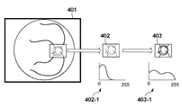
S301において、制御部300は、図4に示すように、眼底基準画像401(第1の眼底画像)を取得する。
In S301, the
S302において、制御部300は、眼底基準画像401の一部領域(第1の特徴領域)を基準テンプレート402として切り出す(抽出する)。基準テンプレート402は、ヒストグラム402−1に示される輝度分布を有している。図4に示す例では、眼底基準画像401の一部領域は視神経乳頭を含む領域であるが、必ずしも視神経乳頭領域に限定されない。他の血管領域であってもよい。
In S <b> 302, the
S303において、制御部300は、基準テンプレート402へ、当該基準テンプレート402のコントラストを強調するための処理(例えば、階調変換処理、階調均一化処理等)を施して輝度変換を行い、基準テンプレート403(第1のテンプレート)を取得する(第1のテンプレート生成処理)。
In step S <b> 303, the
階調均一化処理後の基準テンプレート403は、ヒストグラム403−1の輝度分布を有しており、輝度分布及びコントラストが改善されている。なお、エッジ検出フィルタを適用してさらにコントラストを改善してもよい。
The
S304において、制御部300は、眼底対象画像(第2の眼底画像)を取得する。
In S304, the
S305において、制御部300は、眼底対象画像の一部領域(第2の特徴領域)を、基準テンプレート401の切り出し位置および切り出しサイズに基づいて、対象テンプレート(不図示)として切り出す。
In step S <b> 305, the
S306において、制御部300は、S305で切り出された対象テンプレートへ階調均一化処理を施して輝度変換を行い、図5に示すように、対象テンプレート503(第2のテンプレート)を取得する(第2のテンプレート生成処理)。
In S306, the
S307において、制御部300は、基準テンプレート403と対象テンプレート503とを用いて、二次元(X,Y)方向の変位量および/または変位方向を算出することによって、眼底Erの移動量(位置ずれ)を算出する。また、制御部300は、基準テンプレート403と対象テンプレート503との、テンプレート同士の類似度を算出する(類似度算出処理)。類似度は、例えば基準テンプレート403と対象テンプレート503とをマッチングした際の、テンプレートの全画素数に対する重複領域の画素数の割合として算出することができる。あるいは、基準テンプレート403に対するヒストグラム403−1の輝度分布と、対象テンプレート503に対するヒストグラムの輝度分布(不図示)との相関度を類似度として算出してもよい。また、基準テンプレート403と対象テンプレート503とから求められる相互相関に関する値(例えば、相互相関係数)を類似度としてもよい。
In S307, the
S308において、制御部300は、S307で算出された類似度が閾値以上であるか否かを判定する。類似度が閾値以上であると判定された場合(S308;YES)、S309へ進む。一方、類似度が閾値未満であると判定された場合(S308;NO)、S301に戻る。
In S308, the
なお、被検眼Eの瞼や睫毛の影響により、階調均一化処理を行っても眼底トラッキングの精度が十分に発揮できないことがある。そのような場合を想定して、基準テンプレート403と対象テンプレート503とから求められる相互相関に関する値(例えば、相互相関係数)を類似度として算出し、類似度の低下を判断してもよい。例えば、テンプレート同士が完全に一致するときの類似度を1とした場合、相互相関係数の最大値が類似度0.4(閾値)以下で眼底トラッキングの精度が不十分と判定してもよい。なお、閾値を類似度0.4以下としたが、閾値は経験則により任意の値を設定してもよい。
Note that the accuracy of fundus tracking may not be sufficiently exerted even if gradation equalization processing is performed due to the influence of eyelashes or eyelashes of the eye E to be examined. Assuming such a case, a value related to the cross-correlation (for example, cross-correlation coefficient) obtained from the
S309において、制御部300は、算出された眼底Erの移動量(位置ずれ)に応じて、Xスキャナ122−1、Yスキャナ122−2を制御し、光路L1の測定光が常に眼底Er上の同一領域に照射されるように断層画像の取得位置(走査位置)を変更補正する(位置補正処理)。
In S309, the
以上説明したような一連の眼底トラッキング動作によって、光源130から眼底Erに照射される測定光の照射位置は、常に被検眼眼底Erの動きを追いかける様に移動する。そのため、安定した断層画像の撮影が可能となる。そして、この一連の眼底トラッキング動作は、被検眼Eの検査を終了するまで継続する。 By the series of fundus tracking operations as described above, the irradiation position of the measurement light irradiated from the light source 130 to the fundus Er always moves so as to follow the movement of the fundus Er to be examined. As a result, stable tomographic imaging can be performed. This series of fundus tracking operations continues until the examination of the eye E is completed.
以上述べたように、本実施形態に係る光干渉断層撮影装置では階調均一化処理による輝度変換を行ったテンプレートを用いて眼底トラッキングを行い、その結果に基づいて走査位置の補正することで変形の少ない好適な断層画像を得ることができる。 As described above, the optical coherence tomography apparatus according to this embodiment performs fundus tracking using a template that has been subjected to luminance conversion by gradation equalization processing, and deforms by correcting the scanning position based on the result. Therefore, it is possible to obtain a suitable tomographic image with little.
なお、本実施形態では、2つのスキャナを用いて2次元走査する点走査型SLOによる眼底観察画像を用いた眼底トラッキングを行っているが、他の手法を用いてこれを実施してもよい。例えば、ラインビームを1次元に走査するライン走査タイプも適用できる。また、眼底を広範囲に照射可能な赤外光と赤外線CCDとを組み合わせた二次元眼底観察画像を用いて眼底トラッキングを行うことができる。また、光源から形成される任意のパターンを眼底に投影し、その反射光を用いて眼底トラッキングを行うことも可能である。また、OCT光学系の走査タイプもSLO光学系と同様の手法が適用できるし、走査せずに、エリアセンサを用いて、一括して撮像するフルフィールドタイプも適用できる。 Note that in this embodiment, fundus tracking is performed using a fundus observation image by a point scanning SLO that performs two-dimensional scanning using two scanners, but this may be performed using other methods. For example, a line scanning type in which a line beam is scanned one-dimensionally can also be applied. Also, fundus tracking can be performed using a two-dimensional fundus observation image in which infrared light capable of irradiating the fundus over a wide range and an infrared CCD are combined. It is also possible to project an arbitrary pattern formed from the light source onto the fundus and perform fundus tracking using the reflected light. In addition, the same method as the SLO optical system can be applied to the scanning type of the OCT optical system, and a full field type in which images are collectively collected using an area sensor without scanning is also applicable.
<断層画像の撮影方法>
次に、本実施形態の光干渉断層撮像装置を用いた断層画像の撮影方法について説明する。検者は制御部300上の図示しないスイッチを操作して撮影を開始する。制御部300は、撮影開始の指示に従い、定期的にラインセンサ204から出力される干渉光に基づいて記録用の断層画像の生成を開始する。
<Tomographic imaging method>
Next, a tomographic image capturing method using the optical coherence tomography apparatus according to the present embodiment will be described. The examiner operates a switch (not shown) on the
ここでラインセンサ204から出力される干渉光は、回折格子202で分光された周波数毎の信号である。制御部300は、ラインセンサ204の信号をFFT(Fast Fourier Transform)処理し、眼底Er上のある一点における深さ方向の情報を生成する。この眼底Er上のある一点における深さ方向の情報生成を、Aスキャンと呼ぶ。
Here, the interference light output from the
そして、眼底Erに照射される測定光は、Xスキャナ122−1とYスキャナ122−2との少なくとも何れか一方を駆動制御することによって、眼底Er上を任意に走査可能である。Xスキャナ122−1およびYスキャナ122−2により、測定光を被検眼上で走査することができる。 The measurement light emitted to the fundus Er can be arbitrarily scanned on the fundus Er by driving and controlling at least one of the X scanner 122-1 and the Y scanner 122-2. The measurement light can be scanned on the eye to be examined by the X scanner 122-1 and the Y scanner 122-2.
制御部300は、この任意の軌跡による走査を一回行う間に取得される一連の複数のAスキャンを一枚の二次元画像に束ねることにより、眼底Er上の任意の軌跡における断層画像を生成する。
The
さらに、制御部300は、Xスキャナ122−1とYスキャナ122−2との少なくとも何れか一方を駆動制御することによって、前述の任意の軌跡による走査を複数回繰り返す。同じ軌跡の操作を複数回行った場合、眼底Er上の任意の軌跡における複数枚の断層画像を得ることができる。例えば、制御部300はXスキャナ122−1を駆動させてX方向の走査を反復実行し、眼底Erの同一走査線上における複数の断層画像を生成する。また、制御部300はXスキャナ122−1およびYスキャナ122−2を同時に駆動させて円形の操作を反復実行し、眼底Erの同一円上における複数の断層画像を生成することもできる。そして制御部300は、それら複数枚の断層画像を加算平均処理することにより、高画質な一枚の断層画像を生成し、モニタ301に表示する。
Further, the
一方、制御部300は、Xスキャナ122−1とYスキャナ122−2との少なくとも何れか一方を駆動制御することによって、前述の任意の軌跡よる走査をX/Y方向にずらしながら複数回の走査を行うこともできる。例えば、X方向の走査を一定間隔でY方向にずらしながら複数回行うことで、眼底Er上の矩形領域全体を覆う複数枚の断層画像を生成する。そして、制御部300はそれら複数枚の断層画像を合成することで眼底Erの三次元情報を生成し、モニタ301に表示する。図6は、被検眼前眼部Eaの撮影した断層画像の一例であり、Rは網膜を示している。
On the other hand, the
なお、本実施形態では記録用の断層画像を取得する際に、各走査間で走査位置の補正を行うよう制御しているが、観察用の断層画像を取得する際に同様の制御を実施してもよい。その場合、観察用の断層画像においても網膜層の歪みを低減することが可能になる。 In this embodiment, when acquiring a tomographic image for recording, control is performed so as to correct the scanning position between scans. However, similar control is performed when acquiring a tomographic image for observation. May be. In that case, distortion of the retinal layer can be reduced even in the tomographic image for observation.
また、観察用の断層画像を取得する際は、各走査間で走査位置の補正を行うのではなく、眼底Erの移動を検出した時点で走査位置の補正を行ってもよい。観察用の断層画像はリアルタイムの観察動画として表示されるものであり、その表示期間は非常に短い。また、観察用の断層画像は診断に用いられることも無いため、網膜層の多少の歪みは許容可能である。 When acquiring a tomographic image for observation, the scanning position may be corrected when the movement of the fundus oculi Er is detected, instead of correcting the scanning position between each scan. The tomographic image for observation is displayed as a real-time observation moving image, and the display period is very short. In addition, since the tomographic image for observation is not used for diagnosis, some distortion of the retinal layer is acceptable.
(第2実施形態)
<眼底のトラッキング方法>
以下、図7のフローチャートを参照して、被検眼Eの状態を観察するために測定光を被検眼Eの眼底部Erに照射する際、被検眼Eの動きに伴って生じる測定光照射位置のずれを補正する、第2実施形態に係る眼底トラッキング方法の詳細を説明する。
(Second Embodiment)
<Ocular fundus tracking method>
Hereinafter, with reference to the flowchart of FIG. 7, when the measurement light is irradiated to the fundus Er of the eye E to observe the state of the eye E, the measurement light irradiation position generated along with the movement of the eye E is measured. Details of the fundus tracking method according to the second embodiment for correcting the shift will be described.
制御部300は、前述した自動アライメント動作の開始後、第1実施形態と同様に、光路L2による被検眼眼底Erの二次元観察画像の取得動作を開始する。
After starting the above-described automatic alignment operation, the
S701において、制御部300は、撮影済の複数の眼底観察画像のうち、高コントラストな眼底観察画像を眼底基準画像として取得する。なお、眼底観察画像のピントが合っていない場合は、レンズ111(フォーカスレンズ)を駆動させて眼底観察の合焦処理を行った後に眼底基準画像を新たに取得してもよい。
In step S <b> 701, the
S702において、制御部300は、S701で取得された眼底基準画像から血管等の特徴領域を選び出し、切り出し位置及および切り出しサイズを決定し、図4に示すように基準テンプレート401を切り出す。S703−S709の各処理は、S303−S309の各処理と同様であるため、説明を省略する。
In S702, the
なお、S708において類似度が閾値未満となった場合、テンプレートの切り出しに問題がある場合がある。一般的に、眼底トラッキングを高速化するために、できるだけ狭い範囲でテンプレートの切出しを行っている。しかしながら、ピント合わせ不足や眼の疾患等の影響で類似度が低下する場合があり、テンプレート切出し範囲を見直すことで類似度の値が改善することがある。すなわち、類似度が閾値未満となった場合、その後テンプレートを再生成する時に、テンプレート切出しサイズをより大きなサイズに変更する。テンプレート切出しの最大サイズについては、眼底トラッキング許容時間に基づいて決定される。 Note that if the similarity is less than the threshold in S708, there may be a problem in cutting out the template. Generally, in order to speed up fundus tracking, a template is cut out in the narrowest possible range. However, the similarity may decrease due to the effect of insufficient focusing or eye disease, and the similarity value may be improved by reexamining the template cutout range. That is, when the similarity is less than the threshold, the template cut-out size is changed to a larger size when the template is regenerated thereafter. The maximum template cut-out size is determined based on the fundus tracking allowable time.
以上説明したように、本実施形態では、被検眼の眼底観察画像のうち、高コントラストな眼底観察画像を眼底基準画像として取得し、階調均一化処理を施すことで、特徴領域(血管領域等)のコントラストをより高くする。これにより、高精度な眼底トラッキングを行うことができ、被検眼の動きによる撮影断層画像への影響を低減すると共に、高画質な画像を得ることができる。また、眼底トラッキングの対象となる画像の撮影中に被検眼が動いた場合であっても、撮影光軸の偏心による撮影光束の被検眼の瞳孔でのケラレ(蹴られ)や、被検眼が傾くことによる照度ムラの影響を低減することができる。 As described above, in the present embodiment, a high-contrast fundus observation image among the fundus observation images of the eye to be examined is acquired as a fundus reference image and subjected to gradation equalization processing, whereby a feature region (blood vessel region or the like) is obtained. ) To increase the contrast. Thereby, the fundus tracking can be performed with high accuracy, the influence on the tomographic image due to the movement of the eye to be examined can be reduced, and a high-quality image can be obtained. In addition, even when the subject's eye moves while photographing an image that is subject to fundus tracking, vignetting (kicking) of the photographing light flux at the pupil of the subject's eye due to the eccentricity of the photographing optical axis, or the subject's eye is tilted This can reduce the influence of uneven illuminance.
(その他の実施形態)
また、本発明は、以下の処理を実行することによっても実現される。即ち、上述した実施形態の機能を実現するソフトウェア(プログラム)を、ネットワーク又は各種記憶媒体を介してシステム或いは装置に供給し、そのシステム或いは装置のコンピュータ(またはCPUやMPU等)がプログラムを読み出して実行する処理である。
(Other embodiments)
The present invention can also be realized by executing the following processing. That is, software (program) that realizes the functions of the above-described embodiments is supplied to a system or apparatus via a network or various storage media, and a computer (or CPU, MPU, or the like) of the system or apparatus reads the program. It is a process to be executed.
Claims (17)
前記第1の眼底画像の一部の第1の特徴領域のコントラストを強調するように前記第1の特徴領域に対して処理を施して、前記第1の特徴領域に対応する画像を生成する第1の生成手段と、
前記第1の特徴領域に対応する、前記第2の眼底画像の一部の第2の特徴領域のコントラストを強調するように前記第2の特徴領域に対して処理を施して、前記第2の特徴領域に対応する画像を生成する第2の生成手段と、
前記第1の特徴領域に対応する画像と前記第2の特徴領域に対応する画像との位置ずれに基づいて、前記被検眼の断層画像の取得位置を補正する位置補正手段と、
を備えることを特徴とする眼科装置。 Fundus image acquisition means for acquiring a first fundus image of the eye to be examined and a second fundus image of the eye to be inspected taken at a time different from the first fundus image;
The first feature area is processed so as to emphasize the contrast of a part of the first feature area of the first fundus image, and an image corresponding to the first feature area is generated. 1 generating means;
The second feature region is processed so as to enhance the contrast of the second feature region of the second fundus image corresponding to the first feature region, and the second feature region Second generation means for generating an image corresponding to the feature region;
Position correcting means for correcting an acquisition position of a tomographic image of the eye to be examined based on a positional shift between an image corresponding to the first feature area and an image corresponding to the second feature area;
An ophthalmologic apparatus comprising:
前記類似度が閾値以上であるか否かを判定する判定手段と、をさらに備え、
前記位置補正手段は、前記判定手段により前記類似度が閾値以上であると判定された場合に、前記断層画像の取得位置を補正することを特徴とする請求項1に記載の眼科装置。 Similarity calculating means for calculating the similarity between the image corresponding to the first feature region and the image corresponding to the second feature region;
Determination means for determining whether the similarity is equal to or greater than a threshold, and
The ophthalmic apparatus according to claim 1, wherein the position correction unit corrects the acquisition position of the tomographic image when the determination unit determines that the similarity is equal to or greater than a threshold value.
前記フォーカスレンズを駆動して合焦処理を行うフォーカスレンズ駆動手段と、をさらに備え、
前記第1の生成手段および前記第2の生成手段は、前記合焦処理が行われた後に、前記第1の特徴領域に対応する画像および前記第2の特徴領域に対応する画像をそれぞれ生成することを特徴とする請求項1乃至7の何れか1項に記載の眼科装置。 A focus lens for taking a fundus image of the eye to be examined ;
A focus lens driving means for driving the focus lens to perform focusing processing, and
The first generation unit and the second generation unit generate an image corresponding to the first feature region and an image corresponding to the second feature region, respectively, after the focusing process is performed. The ophthalmologic apparatus according to claim 1, wherein the ophthalmologic apparatus is provided.
前記第2の特徴領域のコントラストを強調するように前記第2の特徴領域に対して施す処理は、前記第2の特徴領域の階調を変換する階調変換処理であることを特徴とする請求項1乃至8の何れか1項に記載の眼科装置。 The first process applied to the first feature area so to emphasize the contrast characteristic region of the Ri gradation conversion processing der for converting the gray level of the first feature area,
Process is characterized by the tone conversion process der Rukoto for converting the gray level of the second characteristic region is subjected to the second feature region so as to emphasize the contrast of the second feature area The ophthalmologic apparatus according to any one of claims 1 to 8.
前記第2の特徴領域のコントラストを強調するように前記第2の特徴領域に対して施す処理は、前記第2の特徴領域の階調を均一化する階調均一化処理であることを特徴とする請求項1乃至9の何れか1項に記載の眼科装置。 The first process applied to the first feature area so to emphasize the contrast characteristic region of the Ri gradation uniformization process der to equalize the tone of the first feature area,
The process applied to the second feature region so as to emphasize the contrast of the second feature area, wherein the gradation uniformization process der Rukoto to equalize the tone of the second feature area The ophthalmologic apparatus according to any one of claims 1 to 9.
前記眼底画像取得手段は、前記眼底画像取得用の走査手段により走査された光の前記被検眼からの反射光に基づいて前記第1の眼底画像と前記第2の眼底画像とを取得し、
前記位置補正手段は、前記第1の特徴領域に対応する画像と前記第2の特徴領域に対応する画像との位置ずれに基づいて、前記断層画像取得用の走査手段の走査位置を補正することにより前記被検眼の断層画像の取得位置を補正することを特徴とする請求項1乃至10の何れか1項に記載の眼科装置。 It further comprises scanning means for acquiring fundus images and scanning means for acquiring tomographic images for scanning light irradiated from a light source on the eye to be examined.
The fundus image acquisition means acquires the first fundus image and the second fundus image based on the reflected light from the eye to be examined, which has been scanned by the scanning means for fundus image acquisition,
The position correcting unit corrects a scanning position of the scanning unit for acquiring the tomographic image based on a positional shift between an image corresponding to the first feature region and an image corresponding to the second feature region. The ophthalmologic apparatus according to any one of claims 1 to 10, wherein an acquisition position of a tomographic image of the eye to be examined is corrected by:
前記位置補正手段は、前記算出された位置ずれに基づいて、前記被検眼の断層画像の取得位置を補正することを特徴とする請求項1乃至11のいずれか1項に記載の眼科装置。 A calculation unit for calculating a positional shift between the image corresponding to the first feature region and the image corresponding to the second feature region;
The ophthalmologic apparatus according to claim 1, wherein the position correction unit corrects an acquisition position of a tomographic image of the eye to be examined based on the calculated positional deviation.
前記第1の眼底画像の一部の第1の特徴領域のコントラストを強調するように前記第1の特徴領域に対して処理を施して、前記第1の特徴領域に対応する画像を生成する第1の生成手段と、
前記第1の特徴領域に対応する、前記第2の眼底画像の一部の第2の特徴領域のコントラストを強調するように前記第2の特徴領域に対して処理を施して、前記第2の特徴領域に対応する画像を生成する第2の生成手段と、
前記第1の特徴領域に対応する画像と前記第2の特徴領域に対応する画像との位置ずれを算出する算出手段と、
を備えることを特徴とする眼科装置。 Fundus image acquisition means for acquiring a first fundus image of the eye to be examined and a second fundus image of the eye to be inspected taken at a time different from the first fundus image;
The first feature area is processed so as to emphasize the contrast of a part of the first feature area of the first fundus image, and an image corresponding to the first feature area is generated. 1 generating means;
The second feature region is processed so as to enhance the contrast of the second feature region of the second fundus image corresponding to the first feature region, and the second feature region Second generation means for generating an image corresponding to the feature region;
Calculating means for calculating a displacement between an image corresponding to the first feature area and an image corresponding to the second feature area;
An ophthalmologic apparatus comprising:
前記第1の眼底画像の一部の第1の特徴領域のコントラストを強調するように前記第1の特徴領域に対して処理を施して、前記第1の特徴領域に対応する画像を生成する第1の生成工程と、
前記第1の特徴領域に対応する、前記第2の眼底画像の一部の第2の特徴領域のコントラストを強調するように前記第2の特徴領域に対して処理を施して、前記第2の特徴領域に対応する画像を生成する第2の生成工程と、
前記第1の特徴領域に対応する画像と前記第2の特徴領域に対応する画像との位置ずれに基づいて、前記被検眼の断層画像の取得位置を補正する位置補正工程と、
を有することを特徴とする眼科装置の制御方法。 A fundus image acquisition step of acquiring a first fundus image of the eye to be examined and a second fundus image of the eye to be inspected taken at a time different from the first fundus image;
The first feature area is processed so as to emphasize the contrast of a part of the first feature area of the first fundus image, and an image corresponding to the first feature area is generated. 1 generation process;
The second feature region is processed so as to enhance the contrast of the second feature region of the second fundus image corresponding to the first feature region, and the second feature region A second generation step of generating an image corresponding to the feature region;
A position correction step of correcting the acquisition position of the tomographic image of the eye to be examined based on the positional deviation between the image corresponding to the first feature region and the image corresponding to the second feature region;
A method for controlling an ophthalmic apparatus, comprising:
前記第1の眼底画像の一部の第1の特徴領域のコントラストを強調するように前記第1の特徴領域に対して処理を施して、前記第1の特徴領域に対応する画像を生成する第1の生成工程と、
前記第1の特徴領域に対応する、前記第2の眼底画像の一部の第2の特徴領域のコントラストを強調するように前記第2の特徴領域に対して処理を施して、前記第2の特徴領域に対応する画像を生成する第2の生成工程と、
前記第1の特徴領域に対応する画像と前記第2の特徴領域に対応する画像との位置ずれを算出する算出工程と、
を有することを特徴とする眼科装置の制御方法。 A fundus image acquisition step of acquiring a first fundus image of the eye to be examined and a second fundus image of the eye to be inspected taken at a time different from the first fundus image;
The first feature area is processed so as to emphasize the contrast of a part of the first feature area of the first fundus image, and an image corresponding to the first feature area is generated. 1 generation process;
The second feature region is processed so as to enhance the contrast of the second feature region of the second fundus image corresponding to the first feature region, and the second feature region A second generation step of generating an image corresponding to the feature region;
A calculation step of calculating a positional shift between an image corresponding to the first feature region and an image corresponding to the second feature region;
A method for controlling an ophthalmic apparatus, comprising:
Priority Applications (5)
| Application Number | Priority Date | Filing Date | Title |
|---|---|---|---|
| JP2012190617A JP6062688B2 (en) | 2012-08-30 | 2012-08-30 | Ophthalmic apparatus, method for controlling ophthalmic apparatus, and program |
| US13/967,320 US8939583B2 (en) | 2012-08-30 | 2013-08-14 | Ophthalmic apparatus, method of controlling ophthalmic apparatus and storage medium |
| EP13180774.5A EP2702930A1 (en) | 2012-08-30 | 2013-08-16 | Ophthalmic apparatus, method of controlling ophthalmic apparatus and storage medium |
| KR1020130100138A KR101630239B1 (en) | 2012-08-30 | 2013-08-23 | Ophthalmic apparatus, method of controlling ophthalmic apparatus and storage medium |
| CN201310386753.6A CN103654712B (en) | 2012-08-30 | 2013-08-30 | The control method of Ophthalmologic apparatus and Ophthalmologic apparatus |
Applications Claiming Priority (1)
| Application Number | Priority Date | Filing Date | Title |
|---|---|---|---|
| JP2012190617A JP6062688B2 (en) | 2012-08-30 | 2012-08-30 | Ophthalmic apparatus, method for controlling ophthalmic apparatus, and program |
Publications (3)
| Publication Number | Publication Date |
|---|---|
| JP2014045907A JP2014045907A (en) | 2014-03-17 |
| JP2014045907A5 JP2014045907A5 (en) | 2015-10-15 |
| JP6062688B2 true JP6062688B2 (en) | 2017-01-18 |
Family
ID=48985666
Family Applications (1)
| Application Number | Title | Priority Date | Filing Date |
|---|---|---|---|
| JP2012190617A Active JP6062688B2 (en) | 2012-08-30 | 2012-08-30 | Ophthalmic apparatus, method for controlling ophthalmic apparatus, and program |
Country Status (5)
| Country | Link |
|---|---|
| US (1) | US8939583B2 (en) |
| EP (1) | EP2702930A1 (en) |
| JP (1) | JP6062688B2 (en) |
| KR (1) | KR101630239B1 (en) |
| CN (1) | CN103654712B (en) |
Cited By (2)
| Publication number | Priority date | Publication date | Assignee | Title |
|---|---|---|---|---|
| CN109965843A (en) * | 2019-03-14 | 2019-07-05 | 华南师范大学 | A kind of eye movements system passing picture based on filtering |
| JP7145554B1 (en) | 2021-11-24 | 2022-10-03 | 今西医療機器株式会社 | Dry hydroponic cultivation unit and method of manufacturing dry hydroponic cultivation unit |
Families Citing this family (25)
| Publication number | Priority date | Publication date | Assignee | Title |
|---|---|---|---|---|
| WO2012026597A1 (en) * | 2010-08-27 | 2012-03-01 | ソニー株式会社 | Image processing apparatus and method |
| JP6184114B2 (en) * | 2013-01-31 | 2017-08-23 | キヤノン株式会社 | Optical coherence tomography apparatus and control method thereof |
| JP6207221B2 (en) * | 2013-04-30 | 2017-10-04 | キヤノン株式会社 | Optical tomography system |
| DK3139815T3 (en) * | 2014-05-08 | 2019-02-11 | Mimo Ag | Method for Obtaining Optical Coherence Tomography Imaging Data of a Human Eye |
| JP2016083240A (en) * | 2014-10-27 | 2016-05-19 | 株式会社トーメーコーポレーション | Ophthalmologic apparatus |
| AU2014280958B2 (en) * | 2014-12-24 | 2017-08-31 | Canon Kabushiki Kaisha | Registration across frame boundaries in AO-SLO capture |
| JP6812089B2 (en) * | 2015-01-08 | 2021-01-13 | キヤノン株式会社 | Ophthalmic equipment, control methods and programs |
| JP6586615B2 (en) * | 2015-01-30 | 2019-10-09 | 株式会社トーメーコーポレーション | Ophthalmic apparatus and control method thereof |
| JP6490501B2 (en) * | 2015-06-09 | 2019-03-27 | 株式会社トプコン | Ophthalmic examination system |
| JP2017158836A (en) * | 2016-03-10 | 2017-09-14 | キヤノン株式会社 | Ophthalmologic apparatus and imaging method |
| US9867538B2 (en) * | 2016-03-21 | 2018-01-16 | Canon Kabushiki Kaisha | Method for robust eye tracking and ophthalmologic apparatus therefor |
| US10832051B1 (en) * | 2016-06-13 | 2020-11-10 | Facebook Technologies, Llc | Eye tracking using optical coherence methods |
| JP7249278B2 (en) * | 2016-12-15 | 2023-03-30 | アルコン インコーポレイティド | Adaptive image registration for ophthalmic surgery |
| JP6866167B2 (en) * | 2017-01-18 | 2021-04-28 | キヤノン株式会社 | Information processing equipment, information processing methods and programs |
| US10888220B2 (en) * | 2017-03-17 | 2021-01-12 | Canon Kabushiki Kaisha | Information processing apparatus, image generation method, and computer-readable medium, with acquisition of correction coefficient by performing arithmetic operation on first and second parameters |
| EP3624671B1 (en) * | 2017-05-18 | 2024-04-24 | Welch Allyn, Inc. | Fundus image capturing |
| CN107212852B (en) * | 2017-05-31 | 2023-09-01 | 执鼎医疗科技(杭州)有限公司 | Correction method and device for realizing scanning positions of various scanning imaging devices |
| EP3668369B1 (en) * | 2017-08-14 | 2021-03-31 | Optos plc | Retinal position tracking |
| JP2019041841A (en) | 2017-08-30 | 2019-03-22 | 株式会社トプコン | Ophthalmologic apparatus and control method thereof |
| US10963046B1 (en) | 2018-05-17 | 2021-03-30 | Facebook Technologies, Llc | Drift corrected eye tracking |
| JP7123626B2 (en) * | 2018-05-24 | 2022-08-23 | キヤノン株式会社 | Fundus imaging device and its control method |
| US10993613B2 (en) | 2018-12-21 | 2021-05-04 | Welch Allyn, Inc. | Fundus image capturing |
| CN110705611A (en) * | 2019-09-17 | 2020-01-17 | 平安科技(深圳)有限公司 | Fundus image sample expansion method, device, medium, and electronic apparatus |
| CN111881084B (en) * | 2020-07-27 | 2023-09-19 | 南京慧目信息技术有限公司 | Ophthalmic data standardization method |
| CN113570520A (en) * | 2021-07-28 | 2021-10-29 | 苏州微景医学科技有限公司 | Optical fiber image correction method, device and computer readable storage medium |
Family Cites Families (15)
| Publication number | Priority date | Publication date | Assignee | Title |
|---|---|---|---|---|
| JP2001137192A (en) * | 1999-11-15 | 2001-05-22 | Canon Inc | Ophthalmic imaging equipment, method and recording medium |
| JP2004041371A (en) * | 2002-07-10 | 2004-02-12 | Canon Inc | Ophthalmological device |
| JP2005087608A (en) | 2003-09-19 | 2005-04-07 | Canon Inc | Ophthalmologic photographing apparatus |
| US7805009B2 (en) | 2005-04-06 | 2010-09-28 | Carl Zeiss Meditec, Inc. | Method and apparatus for measuring motion of a subject using a series of partial images from an imaging system |
| DE602006020523D1 (en) * | 2005-07-01 | 2011-04-21 | Nidek Kk | Eye examination device |
| EP1976424B1 (en) * | 2006-01-19 | 2011-09-21 | Optovue, Inc. | A method of eye examination by optical coherence tomography |
| JP4854389B2 (en) * | 2006-06-15 | 2012-01-18 | 株式会社トプコン | Spectral fundus measuring apparatus and measuring method thereof |
| JP4822969B2 (en) | 2006-07-27 | 2011-11-24 | 株式会社ニデック | Ophthalmic imaging equipment |
| JP5355316B2 (en) | 2009-09-10 | 2013-11-27 | キヤノン株式会社 | Template image evaluation method and biological motion detection apparatus |
| JP5570195B2 (en) * | 2009-12-07 | 2014-08-13 | 株式会社ニデック | OCT equipment |
| JP5528205B2 (en) * | 2010-05-17 | 2014-06-25 | キヤノン株式会社 | Ophthalmologic apparatus, ophthalmologic apparatus control method, adaptive optical system, image generation apparatus, image generation method, program |
| JP5818409B2 (en) | 2010-06-17 | 2015-11-18 | キヤノン株式会社 | Fundus imaging apparatus and control method thereof |
| JP5820154B2 (en) | 2010-07-05 | 2015-11-24 | キヤノン株式会社 | Ophthalmic apparatus, ophthalmic system, and storage medium |
| JP5735790B2 (en) * | 2010-12-02 | 2015-06-17 | 株式会社ニデック | Ophthalmic imaging equipment |
| JP5731815B2 (en) * | 2010-12-20 | 2015-06-10 | キヤノン株式会社 | Imaging method, imaging apparatus, and program |
-
2012
- 2012-08-30 JP JP2012190617A patent/JP6062688B2/en active Active
-
2013
- 2013-08-14 US US13/967,320 patent/US8939583B2/en not_active Expired - Fee Related
- 2013-08-16 EP EP13180774.5A patent/EP2702930A1/en not_active Withdrawn
- 2013-08-23 KR KR1020130100138A patent/KR101630239B1/en active IP Right Grant
- 2013-08-30 CN CN201310386753.6A patent/CN103654712B/en active Active
Cited By (3)
| Publication number | Priority date | Publication date | Assignee | Title |
|---|---|---|---|---|
| CN109965843A (en) * | 2019-03-14 | 2019-07-05 | 华南师范大学 | A kind of eye movements system passing picture based on filtering |
| CN109965843B (en) * | 2019-03-14 | 2022-05-24 | 华南师范大学 | Eye movement system based on filtering image transmission |
| JP7145554B1 (en) | 2021-11-24 | 2022-10-03 | 今西医療機器株式会社 | Dry hydroponic cultivation unit and method of manufacturing dry hydroponic cultivation unit |
Also Published As
| Publication number | Publication date |
|---|---|
| KR101630239B1 (en) | 2016-06-14 |
| JP2014045907A (en) | 2014-03-17 |
| EP2702930A1 (en) | 2014-03-05 |
| US20140063460A1 (en) | 2014-03-06 |
| CN103654712A (en) | 2014-03-26 |
| CN103654712B (en) | 2015-10-14 |
| US8939583B2 (en) | 2015-01-27 |
| KR20140029224A (en) | 2014-03-10 |
Similar Documents
| Publication | Publication Date | Title |
|---|---|---|
| JP6062688B2 (en) | Ophthalmic apparatus, method for controlling ophthalmic apparatus, and program | |
| JP5236089B1 (en) | Optical coherence tomography apparatus, control method of optical coherence tomography apparatus, and program | |
| JP6460618B2 (en) | Optical coherence tomography apparatus and control method thereof | |
| JP5822485B2 (en) | Image processing apparatus, image processing method, image processing system, SLO apparatus, and program | |
| US9033500B2 (en) | Optical coherence tomography and method thereof | |
| US9554700B2 (en) | Optical coherence tomographic imaging apparatus and method of controlling the same | |
| JP2011135933A (en) | Retinal function measuring apparatus | |
| JP6776076B2 (en) | OCT device | |
| JP2015029558A (en) | Image processing system, and image processing method | |
| US20170258326A1 (en) | Ophthalmologic apparatus and imaging method | |
| WO2016017664A1 (en) | Tomography device | |
| JP6633468B2 (en) | Blood flow measurement device | |
| JP7096392B2 (en) | Ophthalmic equipment | |
| JP6274728B2 (en) | Optical coherence tomography apparatus and control method thereof | |
| JP6779674B2 (en) | OCT device | |
| JP5649679B2 (en) | Optical coherence tomography apparatus, control method of optical coherence tomography apparatus, and program | |
| JP6486427B2 (en) | Optical coherence tomography apparatus and control method thereof | |
| JP7123626B2 (en) | Fundus imaging device and its control method | |
| WO2019198629A1 (en) | Image processing device and control method for same | |
| JP2016077454A (en) | Ophthalmologic device | |
| WO2017033670A1 (en) | Blood flow measuring device |
Legal Events
| Date | Code | Title | Description |
|---|---|---|---|
| A521 | Request for written amendment filed |
Free format text: JAPANESE INTERMEDIATE CODE: A523 Effective date: 20150827 |
|
| A621 | Written request for application examination |
Free format text: JAPANESE INTERMEDIATE CODE: A621 Effective date: 20150827 |
|
| A977 | Report on retrieval |
Free format text: JAPANESE INTERMEDIATE CODE: A971007 Effective date: 20160518 |
|
| A131 | Notification of reasons for refusal |
Free format text: JAPANESE INTERMEDIATE CODE: A131 Effective date: 20160523 |
|
| A521 | Request for written amendment filed |
Free format text: JAPANESE INTERMEDIATE CODE: A523 Effective date: 20160616 |
|
| TRDD | Decision of grant or rejection written | ||
| A01 | Written decision to grant a patent or to grant a registration (utility model) |
Free format text: JAPANESE INTERMEDIATE CODE: A01 Effective date: 20161118 |
|
| A61 | First payment of annual fees (during grant procedure) |
Free format text: JAPANESE INTERMEDIATE CODE: A61 Effective date: 20161215 |
|
| R151 | Written notification of patent or utility model registration |
Ref document number: 6062688 Country of ref document: JP Free format text: JAPANESE INTERMEDIATE CODE: R151 |