JP6057900B2 - Apparatus and method for securing a suture anchor to hard tissue - Google Patents
Apparatus and method for securing a suture anchor to hard tissue Download PDFInfo
- Publication number
- JP6057900B2 JP6057900B2 JP2013529522A JP2013529522A JP6057900B2 JP 6057900 B2 JP6057900 B2 JP 6057900B2 JP 2013529522 A JP2013529522 A JP 2013529522A JP 2013529522 A JP2013529522 A JP 2013529522A JP 6057900 B2 JP6057900 B2 JP 6057900B2
- Authority
- JP
- Japan
- Prior art keywords
- suture
- tool
- anchor
- thermoplastic
- hard tissue
- Prior art date
- Legal status (The legal status is an assumption and is not a legal conclusion. Google has not performed a legal analysis and makes no representation as to the accuracy of the status listed.)
- Expired - Fee Related
Links
Images


Classifications
-
- A—HUMAN NECESSITIES
- A61—MEDICAL OR VETERINARY SCIENCE; HYGIENE
- A61B—DIAGNOSIS; SURGERY; IDENTIFICATION
- A61B17/00—Surgical instruments, devices or methods, e.g. tourniquets
- A61B17/04—Surgical instruments, devices or methods, e.g. tourniquets for suturing wounds; Holders or packages for needles or suture materials
- A61B17/0401—Suture anchors, buttons or pledgets, i.e. means for attaching sutures to bone, cartilage or soft tissue; Instruments for applying or removing suture anchors
-
- A—HUMAN NECESSITIES
- A61—MEDICAL OR VETERINARY SCIENCE; HYGIENE
- A61B—DIAGNOSIS; SURGERY; IDENTIFICATION
- A61B17/00—Surgical instruments, devices or methods, e.g. tourniquets
- A61B17/11—Surgical instruments, devices or methods, e.g. tourniquets for performing anastomosis; Buttons for anastomosis
-
- A—HUMAN NECESSITIES
- A61—MEDICAL OR VETERINARY SCIENCE; HYGIENE
- A61F—FILTERS IMPLANTABLE INTO BLOOD VESSELS; PROSTHESES; DEVICES PROVIDING PATENCY TO, OR PREVENTING COLLAPSING OF, TUBULAR STRUCTURES OF THE BODY, e.g. STENTS; ORTHOPAEDIC, NURSING OR CONTRACEPTIVE DEVICES; FOMENTATION; TREATMENT OR PROTECTION OF EYES OR EARS; BANDAGES, DRESSINGS OR ABSORBENT PADS; FIRST-AID KITS
- A61F2/00—Filters implantable into blood vessels; Prostheses, i.e. artificial substitutes or replacements for parts of the body; Appliances for connecting them with the body; Devices providing patency to, or preventing collapsing of, tubular structures of the body, e.g. stents
- A61F2/02—Prostheses implantable into the body
- A61F2/08—Muscles; Tendons; Ligaments
- A61F2/0811—Fixation devices for tendons or ligaments
-
- A—HUMAN NECESSITIES
- A61—MEDICAL OR VETERINARY SCIENCE; HYGIENE
- A61L—METHODS OR APPARATUS FOR STERILISING MATERIALS OR OBJECTS IN GENERAL; DISINFECTION, STERILISATION OR DEODORISATION OF AIR; CHEMICAL ASPECTS OF BANDAGES, DRESSINGS, ABSORBENT PADS OR SURGICAL ARTICLES; MATERIALS FOR BANDAGES, DRESSINGS, ABSORBENT PADS OR SURGICAL ARTICLES
- A61L17/00—Materials for surgical sutures or for ligaturing blood vessels ; Materials for prostheses or catheters
- A61L17/06—At least partially resorbable materials
- A61L17/10—At least partially resorbable materials containing macromolecular materials
-
- A—HUMAN NECESSITIES
- A61—MEDICAL OR VETERINARY SCIENCE; HYGIENE
- A61B—DIAGNOSIS; SURGERY; IDENTIFICATION
- A61B17/00—Surgical instruments, devices or methods, e.g. tourniquets
- A61B2017/00004—(bio)absorbable, (bio)resorbable, resorptive
-
- A—HUMAN NECESSITIES
- A61—MEDICAL OR VETERINARY SCIENCE; HYGIENE
- A61B—DIAGNOSIS; SURGERY; IDENTIFICATION
- A61B17/00—Surgical instruments, devices or methods, e.g. tourniquets
- A61B2017/00831—Material properties
- A61B2017/00955—Material properties thermoplastic
-
- A—HUMAN NECESSITIES
- A61—MEDICAL OR VETERINARY SCIENCE; HYGIENE
- A61B—DIAGNOSIS; SURGERY; IDENTIFICATION
- A61B17/00—Surgical instruments, devices or methods, e.g. tourniquets
- A61B17/04—Surgical instruments, devices or methods, e.g. tourniquets for suturing wounds; Holders or packages for needles or suture materials
- A61B17/0401—Suture anchors, buttons or pledgets, i.e. means for attaching sutures to bone, cartilage or soft tissue; Instruments for applying or removing suture anchors
- A61B2017/0409—Instruments for applying suture anchors
-
- A—HUMAN NECESSITIES
- A61—MEDICAL OR VETERINARY SCIENCE; HYGIENE
- A61B—DIAGNOSIS; SURGERY; IDENTIFICATION
- A61B17/00—Surgical instruments, devices or methods, e.g. tourniquets
- A61B17/04—Surgical instruments, devices or methods, e.g. tourniquets for suturing wounds; Holders or packages for needles or suture materials
- A61B17/0401—Suture anchors, buttons or pledgets, i.e. means for attaching sutures to bone, cartilage or soft tissue; Instruments for applying or removing suture anchors
- A61B2017/0414—Suture anchors, buttons or pledgets, i.e. means for attaching sutures to bone, cartilage or soft tissue; Instruments for applying or removing suture anchors having a suture-receiving opening, e.g. lateral opening
-
- A—HUMAN NECESSITIES
- A61—MEDICAL OR VETERINARY SCIENCE; HYGIENE
- A61B—DIAGNOSIS; SURGERY; IDENTIFICATION
- A61B17/00—Surgical instruments, devices or methods, e.g. tourniquets
- A61B17/04—Surgical instruments, devices or methods, e.g. tourniquets for suturing wounds; Holders or packages for needles or suture materials
- A61B17/0401—Suture anchors, buttons or pledgets, i.e. means for attaching sutures to bone, cartilage or soft tissue; Instruments for applying or removing suture anchors
- A61B2017/042—Suture anchors, buttons or pledgets, i.e. means for attaching sutures to bone, cartilage or soft tissue; Instruments for applying or removing suture anchors plastically deformed during insertion
- A61B2017/0422—Suture anchors, buttons or pledgets, i.e. means for attaching sutures to bone, cartilage or soft tissue; Instruments for applying or removing suture anchors plastically deformed during insertion by insertion of a separate member into the body of the anchor
- A61B2017/0424—Suture anchors, buttons or pledgets, i.e. means for attaching sutures to bone, cartilage or soft tissue; Instruments for applying or removing suture anchors plastically deformed during insertion by insertion of a separate member into the body of the anchor the separate member staying in the anchor after placement
-
- A—HUMAN NECESSITIES
- A61—MEDICAL OR VETERINARY SCIENCE; HYGIENE
- A61B—DIAGNOSIS; SURGERY; IDENTIFICATION
- A61B17/00—Surgical instruments, devices or methods, e.g. tourniquets
- A61B17/04—Surgical instruments, devices or methods, e.g. tourniquets for suturing wounds; Holders or packages for needles or suture materials
- A61B17/0401—Suture anchors, buttons or pledgets, i.e. means for attaching sutures to bone, cartilage or soft tissue; Instruments for applying or removing suture anchors
- A61B2017/0446—Means for attaching and blocking the suture in the suture anchor
- A61B2017/0448—Additional elements on or within the anchor
- A61B2017/045—Additional elements on or within the anchor snug fit within the anchor
-
- A—HUMAN NECESSITIES
- A61—MEDICAL OR VETERINARY SCIENCE; HYGIENE
- A61B—DIAGNOSIS; SURGERY; IDENTIFICATION
- A61B17/00—Surgical instruments, devices or methods, e.g. tourniquets
- A61B17/04—Surgical instruments, devices or methods, e.g. tourniquets for suturing wounds; Holders or packages for needles or suture materials
- A61B17/0401—Suture anchors, buttons or pledgets, i.e. means for attaching sutures to bone, cartilage or soft tissue; Instruments for applying or removing suture anchors
- A61B2017/0446—Means for attaching and blocking the suture in the suture anchor
- A61B2017/0458—Longitudinal through hole, e.g. suture blocked by a distal suture knot
-
- A—HUMAN NECESSITIES
- A61—MEDICAL OR VETERINARY SCIENCE; HYGIENE
- A61B—DIAGNOSIS; SURGERY; IDENTIFICATION
- A61B17/00—Surgical instruments, devices or methods, e.g. tourniquets
- A61B17/04—Surgical instruments, devices or methods, e.g. tourniquets for suturing wounds; Holders or packages for needles or suture materials
- A61B17/0401—Suture anchors, buttons or pledgets, i.e. means for attaching sutures to bone, cartilage or soft tissue; Instruments for applying or removing suture anchors
- A61B2017/0464—Suture anchors, buttons or pledgets, i.e. means for attaching sutures to bone, cartilage or soft tissue; Instruments for applying or removing suture anchors for soft tissue
-
- A—HUMAN NECESSITIES
- A61—MEDICAL OR VETERINARY SCIENCE; HYGIENE
- A61B—DIAGNOSIS; SURGERY; IDENTIFICATION
- A61B90/00—Instruments, implements or accessories specially adapted for surgery or diagnosis and not covered by any of the groups A61B1/00 - A61B50/00, e.g. for luxation treatment or for protecting wound edges
- A61B90/03—Automatic limiting or abutting means, e.g. for safety
- A61B2090/033—Abutting means, stops, e.g. abutting on tissue or skin
- A61B2090/034—Abutting means, stops, e.g. abutting on tissue or skin abutting on parts of the device itself
-
- A—HUMAN NECESSITIES
- A61—MEDICAL OR VETERINARY SCIENCE; HYGIENE
- A61F—FILTERS IMPLANTABLE INTO BLOOD VESSELS; PROSTHESES; DEVICES PROVIDING PATENCY TO, OR PREVENTING COLLAPSING OF, TUBULAR STRUCTURES OF THE BODY, e.g. STENTS; ORTHOPAEDIC, NURSING OR CONTRACEPTIVE DEVICES; FOMENTATION; TREATMENT OR PROTECTION OF EYES OR EARS; BANDAGES, DRESSINGS OR ABSORBENT PADS; FIRST-AID KITS
- A61F2/00—Filters implantable into blood vessels; Prostheses, i.e. artificial substitutes or replacements for parts of the body; Appliances for connecting them with the body; Devices providing patency to, or preventing collapsing of, tubular structures of the body, e.g. stents
- A61F2/02—Prostheses implantable into the body
- A61F2/08—Muscles; Tendons; Ligaments
- A61F2/0811—Fixation devices for tendons or ligaments
- A61F2002/0847—Mode of fixation of anchor to tendon or ligament
- A61F2002/0858—Fixation of tendon or ligament between anchor and bone, e.g. interference screws, wedges
Landscapes
- Health & Medical Sciences (AREA)
- Life Sciences & Earth Sciences (AREA)
- Surgery (AREA)
- Animal Behavior & Ethology (AREA)
- Veterinary Medicine (AREA)
- Public Health (AREA)
- Engineering & Computer Science (AREA)
- General Health & Medical Sciences (AREA)
- Biomedical Technology (AREA)
- Heart & Thoracic Surgery (AREA)
- Molecular Biology (AREA)
- Medical Informatics (AREA)
- Nuclear Medicine, Radiotherapy & Molecular Imaging (AREA)
- Rheumatology (AREA)
- Vascular Medicine (AREA)
- Rehabilitation Therapy (AREA)
- Cardiology (AREA)
- Oral & Maxillofacial Surgery (AREA)
- Transplantation (AREA)
- Orthopedic Medicine & Surgery (AREA)
- Chemical & Material Sciences (AREA)
- Materials Engineering (AREA)
- Epidemiology (AREA)
- Surgical Instruments (AREA)
Description
発明の分野
本発明は医療技術の分野にあり、縫合アンカーを、およびそれに伴って縫合糸を、硬組織に固着、特に縫合糸を用いて、軟組織を硬組織に固着するための装置および方法に関し、ここで硬組織は特にヒトまたは動物の患者の骨組織である。本発明はさらに、当該発明に従う方法において適用可能なアンカーに関する。
FIELD OF THE INVENTION The present invention is in the field of medical technology and relates to an apparatus and method for securing a suture anchor and concomitant suture thereto to hard tissue, and in particular, using a suture to secure soft tissue to hard tissue. Here, the hard tissue is in particular bone tissue of a human or animal patient. The invention further relates to an anchor applicable in the method according to the invention.
発明の背景
WO 2009/109057(Woodwelding)は、縫合アンカーを用いて、縫合糸を硬組織に装着するための装置および方法を開示しており、縫合アンカーは熱可塑性特性を有する材料を含み、熱可塑性特性を有する材料のin situでの液化に用いられる振動エネルギを用いて、硬組織開口内に係留される。液化材料は硬組織開口内にある硬組織の穴やほかの適切な構造体の中に浸透し、再固化されると硬組織と縫合アンカーとの間に正嵌合接続をなす。上記公報に開示されている装置は、ハウジング内に振動源、振動ツール、案内管、アンカー、縫合糸、および場合によっては押しブッシングを含む。振動ツールの近位端は振動源に結合され、案内管の近位端はハウジング上に支持され、アンカーは振動ツールの遠位端に配置される。アンカーは、熱可塑性スリーブの形をとる、熱可塑性特性を有する材料を含み、アンカーまたは振動ツールはスリーブを通って到達し、スリーブはアンカーの脚部と、振動ツール、案内管または押しブッシングとの間に固定される。縫合糸ループはアンカーの脚部に保持され、2つの縫合糸端部はアンカーのさらなる部分ならびに振動ツールおよび案内管の中の部分を通って出力され、案内管またはハウジングに装着されることにより、真っ直ぐのまままたは引っ張りを受けたままとなる。
BACKGROUND OF THE INVENTION WO 2009/109057 (Woodwelding) discloses a device and method for attaching a suture to hard tissue using a suture anchor, the suture anchor comprising a material having thermoplastic properties, It is anchored within the hard tissue opening using the vibrational energy used to liquefy the material with plastic properties in situ. The liquefied material penetrates into hard tissue holes and other suitable structures within the hard tissue opening and, when resolidified, provides a positive mating connection between the hard tissue and the suture anchor. The device disclosed in the above publication includes a vibration source, a vibration tool, a guide tube, an anchor, a suture, and possibly a push bushing in the housing. The proximal end of the vibration tool is coupled to a vibration source, the proximal end of the guide tube is supported on the housing, and the anchor is disposed at the distal end of the vibration tool. The anchor includes a material having thermoplastic properties in the form of a thermoplastic sleeve, the anchor or vibration tool reaching through the sleeve, the sleeve being the anchor leg and the vibration tool, guide tube or push bushing. Fixed between. The suture loop is held on the anchor leg, and the two suture ends are output through a further portion of the anchor and a portion in the vibration tool and guide tube, and attached to the guide tube or housing, It remains straight or under tension.
植え込むために、硬組織内に開口が設けられ、装置または縫合アンカーの遠位端はそれぞれ開口内に導入され、熱可塑性スリーブの少なくとも一部は開口内にあり、開口の断面は熱可塑性スリーブの断面よりもわずかに大きく、熱可塑性特性を有する材料は、開口の壁の硬組織近くにあるが、アンカーを開口内に導入しても、スリーブと開口の壁との間に摩擦はない。振動源は起動され、振動エレメント(振動ツールまたは振動ツールに結合されるアンカーの脚)と対向エレメント(振動ツール、案内管または押しブッシングに結合されていないアンカーの脚)との間で挟まれる熱可塑性スリーブの熱可塑性特性を有する材料は、近位および/または遠位面から液化が始まって、硬組織に流れ込み、熱可塑性スリーブは短くなる。熱可塑性スリーブが短くなる間熱可塑性スリーブに対する固定力を維持するために、装置のエレメントは軸方向において互いに相対的に動かされ、これは好ましくは予め張力が与えられたばねによって行なわれ、それと共に少なくとも熱可塑性スリーブと間に熱可塑性スリーブが挟まれるエレメントとが、閉鎖したロードフレームにある。この手段により、縫合アンカーの自動的係留が可能となり、外科医は案内管の遠位端を硬組織の表面上に配置して装置を位置づけて、振動源を起動させるだけでよい。しかし、熱可塑性スリーブの材料を液化させることがなく、係留処理の前に、装置をチェックおよび調整するための特殊な手段が必要である。 For implantation, an opening is provided in the hard tissue, the distal end of the device or suture anchor is each introduced into the opening, at least a portion of the thermoplastic sleeve is within the opening, and the cross-section of the opening is the thermoplastic sleeve. A material that is slightly larger than the cross section and has thermoplastic properties is near the hard tissue of the opening wall, but there is no friction between the sleeve and the opening wall when the anchor is introduced into the opening. The vibration source is activated and heat is pinched between the vibrating element (vibration tool or anchor leg coupled to the vibration tool) and the opposing element (anchor leg not coupled to the vibration tool, guide tube or push bushing) The material having the thermoplastic properties of the plastic sleeve begins to liquefy from the proximal and / or distal surfaces and flows into the hard tissue, shortening the thermoplastic sleeve. In order to maintain a clamping force on the thermoplastic sleeve while the thermoplastic sleeve is shortened, the elements of the device are moved relative to each other in the axial direction, which is preferably done by a pretensioned spring and at least with it. The closed load frame has an element between which the thermoplastic sleeve is sandwiched. This means allows for automatic anchoring of the suture anchor, and the surgeon only has to position the device with the distal end of the guide tube on the surface of the hard tissue and activate the source of vibration. However, the thermoplastic sleeve material does not liquefy and special means are required to check and adjust the device prior to the mooring process.
US 2009/131947(Woodwelding)公報は、縫合アンカーを用いて縫合糸を硬組織に取り付けるための方法を開示しており、振動エネルギを用いて、in situでの液化される熱可塑性材を含む。開示されている方法は、上で簡単に述べた方法と同じ原理に基づいており、縫合糸はアンカーの遠位端部を通って縫われ、アンカーの近位端部は熱可塑性材を含み、アンカーの近位面は、縫合糸の端部を近位方向に引っ張ることにより、振動ツールの遠位面に対して保持される。 US 2009/131947 (Woodwelding) publication discloses a method for attaching a suture to hard tissue using a suture anchor, which includes a thermoplastic material that is liquefied in situ using vibrational energy. The disclosed method is based on the same principle as briefly described above, where the suture is sewn through the distal end of the anchor, the proximal end of the anchor comprising a thermoplastic material, The proximal surface of the anchor is held against the distal surface of the vibration tool by pulling the suture end proximally.
縫合アンカーを伴って縫合糸を硬組織に装着するためのさらなる方法および装置は、公報であるUS-7678134、US-7695495、US-2006/161159、US-2009/192546、US-2009/187216(すべてArthrexのもの)、US-5733307(Dinsdale)、またはUS-6508830(Steiner)に開示されており、開示されたアンカーは、当該目的のために設けられた骨開口内に螺合される干渉ねじ、または好ましくは骨材からなり、かつ当該目的のために設けられた骨開口に圧入されるプラグを含み、縫合糸はねじもしくはプラグによって、またはねじもしくはプラグを用いて開口内に保持される付加的要素によって、保持される。 Further methods and devices for attaching sutures to hard tissue with suture anchors are published in US-7678134, US-7695495, US-2006 / 161159, US-2009 / 192546, US-2009 / 187216 ( All disclosed in Arthrex), US-5733307 (Dinsdale), or US-6508830 (Steiner), and the disclosed anchor is an interference screw that is screwed into a bone opening provided for that purpose. Or a plug preferably made of aggregate and pressed into a bone opening provided for that purpose, wherein the suture is retained in the opening by or using a screw or plug Retained by the target element.
In situで液化され、開口の壁の硬組織を浸透させられる、熱可塑性を有する材料を用いて、硬組織に、たとえばヒトまたは動物の患者の骨組織に設けられる開口内に、物体を係留するための方法は、公報であるUS-7335205、US-7008226、US-2006/0105295、US-2008/109080、US-2009/131947、WO-2009/109057、およびWO-2009/132472に開示されている。これらの公報および出願の開示はすべて、ここに引用により含まれる。 Anchor an object in the hard tissue, for example in the opening provided in the bone tissue of a human or animal patient, using a thermoplastic material that is liquefied in situ and penetrates the hard tissue of the wall of the opening Methods for this are disclosed in publications US-7335205, US-7008226, US-2006 / 0105295, US-2008 / 109080, US-2009 / 131947, WO-2009 / 109057, and WO-2009 / 132472. Yes. The disclosures of all these publications and applications are hereby incorporated by reference.
発明の概要
一般に、本発明の目的は、縫合アンカーを、およびそれに伴って縫合糸を硬組織に固着するためのさらなる装置および方法をもたらすことであり、縫合アンカーを用いて硬組織に固着される縫合糸は特に軟組織を硬組織に装着するのに適し、硬組織は特にヒトまたは動物の患者の骨組織であり、当該方法は、熱可塑性特性を有する材料をin situで液化し、液化した材料を硬組織と接触させるステップを含む。縫合アンカーは、液化材料を開口の硬組織壁内に浸透させることにより、硬組織開口内に固着される、または開口を越えて、すなわち硬組織層のアクセスできない側に(半径方向に流れる)液化材料の延在によって、場合によっては硬組織層のアクセスできない側の硬組織面に対する浸透と組み合わせて、硬組織開口を越えて固着される。再固化されると、硬組織に浸透した材料は、硬組織とアンカーとの間に正嵌合をなす、および/または硬組織開口を越えて広がった材料は、開口を通過できない本体をなす。同じ目的のための従来の方法および装置と比べて、本発明による改良は特に方法および装置の簡易性に関する。
SUMMARY OF THE INVENTION In general, it is an object of the present invention to provide a suture anchor, and concomitantly, additional devices and methods for securing a suture to hard tissue, which is secured to the hard tissue using the suture anchor. The suture is particularly suitable for attaching soft tissue to hard tissue, the hard tissue is in particular bone tissue of a human or animal patient, and the method liquefies a material having thermoplastic properties in situ and liquefied Contacting with hard tissue. The suture anchor is secured within the hard tissue opening by infiltrating the liquefied material into the hard tissue wall of the opening, or liquefies beyond the opening, ie, on the inaccessible side of the hard tissue layer (radially flowing). The extension of the material, in some cases combined with penetration into the hard tissue surface on the inaccessible side of the hard tissue layer, is secured across the hard tissue opening. When resolidified, the material that has penetrated the hard tissue makes a positive fit between the hard tissue and the anchor and / or the material that has spread beyond the hard tissue opening forms a body that cannot pass through the opening. Compared to conventional methods and apparatus for the same purpose, the improvements according to the invention relate in particular to the simplicity of the method and apparatus.
特に、本発明の目的は、縫合アンカーを、ヒトまたは動物の患者の骨組織の開口内に、または開口を越えて固着するためのさらなる装置および方法をもたらすことであり、縫合アンカーおよび固着は、特に縫合アンカーを用いて固定された縫合糸を、硬組織に固着されたアンカーに対して摺動可能にするのに適する。ここでは、硬組織における縫合アンカーの固着、特に皮質性骨層の下の固着は、熱可塑性特性を有し、in situで液化されて硬組織と接する材料が、特に硬組織の自然穴(骨構造)内に、または硬組織に設けられる適切な構造体または空洞内に浸透して、再固化すると、好ましくはアンカーと硬組織との間に正嵌合をなすことにより、行なわれる。本発明の装置および方法は、従来技術に対する改良、特に装置の安定性および簡易性ならびに準備工程を含む固着処理全体を簡易にする改良に関する。本発明の装置および方法は、特に低侵襲性外科手術に適するが、切開手術にも適用可能である。 In particular, it is an object of the present invention to provide a further device and method for anchoring a suture anchor into or beyond an opening in bone tissue of a human or animal patient, It is particularly suitable for making a suture fixed using a suture anchor slidable with respect to an anchor fixed to a hard tissue. Here, the anchoring of suture anchors in hard tissue, in particular under the cortical bone layer, has thermoplastic properties, and the material that is liquefied in situ and in contact with the hard tissue, in particular natural holes in the hard tissue (bones). Infiltration into a suitable structure or cavity provided in the structure) or in the hard tissue and resolidification is preferably performed by making a positive fit between the anchor and the hard tissue. The apparatus and method of the present invention relates to improvements over the prior art, in particular to the stability and simplicity of the apparatus and the simplification of the entire fixing process including preparation steps. The devices and methods of the present invention are particularly suitable for minimally invasive surgery, but are also applicable to open surgery.
上記の目的は、独立請求項に記載されている装置および方法によって達成される。
本発明の装置および方法は、WO2009/109057に開示されている装置および方法のさらなる展開をなし、その開示はここに引用によりその全体が含まれる。当該装置は、遠位ツール端部に配置された場合に、アンカーに働く横方向の力に対する安定性を向上させることに関し、さらにガイドスリーブを不要にすることにより簡易化される。さらに、熱可塑性特性を有する材料の液化について、容易な機械的制御および場合により視覚的制御のための手段を含み得る。さらに、本発明の装置は、外科医によって操作され、かつ縫合糸の取り扱いを容易にするレバーシステム、すなわち縫合糸を取り付け、引っ張り、および動かすための手段を含み得る。本発明による装置は外科医の片手で容易に操作することができ、外科医はこの手の1本の指でレバーシステムを操作することができる。レバーシステムは、インプランテーション処理を簡易にするだけでなく、インプランテーション処理のために装置を用意するステップも簡易にする。
The above objective is accomplished by an apparatus and method as set out in the independent claims.
The apparatus and method of the present invention is a further development of the apparatus and method disclosed in WO2009 / 109057, the disclosure of which is hereby incorporated by reference in its entirety. The device is simplified by eliminating the need for a guide sleeve with respect to improving stability against lateral forces acting on the anchor when placed at the distal tool end. Further, it may include means for easy mechanical control and optionally visual control for liquefaction of materials having thermoplastic properties. In addition, the device of the present invention may include a lever system operated by the surgeon and facilitating the handling of the suture, i.e. means for attaching, pulling and moving the suture. The device according to the invention can be easily operated with one hand of the surgeon, and the surgeon can operate the lever system with one finger of this hand. The lever system not only simplifies the implantation process, but also simplifies the step of preparing the device for the implantation process.
本発明の装置は、エネルギ源に結合するのに適する近位端と、縫合糸を含む縫合アンカーを配置するのに適する遠位端とを有するツールを含む。さらに、当該装置は実質的に管状のインターフェイス片を含み、これはアンカーをツールの遠位端において安定化させる働きをなし、アンカーが硬組織に対して安全に位置づけられ、固着プロシージャの際にはツールと整合したままとなる。インターフェイス片は、固着プロシージャの際には、遠位ツール端の軸方向チャネル内において変位可能であるように、かつツールとともに固着箇所から取り外すことができるよう、設計されている。 The apparatus of the present invention includes a tool having a proximal end suitable for coupling to an energy source and a distal end suitable for placing a suture anchor including a suture. In addition, the device includes a substantially tubular interface piece that serves to stabilize the anchor at the distal end of the tool so that the anchor can be safely positioned relative to the hard tissue and during the fixation procedure. Stay consistent with the tool. The interface piece is designed to be displaceable in the axial channel at the distal tool end during the fixation procedure and to be removed from the fixation location with the tool.
本装置はさらに縫合糸を有するアンカーと、場合によってはエネルギ源とを含むことができ、アンカーはツールの遠位端に配置され、エネルギ源はツールの近位端に結合される。エネルギ源またはそのハウジングは、上記のレバーシステムを保有することができる。アンカーは、熱可塑性スリーブの形で、熱可塑性特性を有する材料を含み、熱可塑性スリーブは遠位ツール面とアンカー脚との間に保持され、固着処理では、少なくとも部分的に液化され、これは好ましくは遠位ツール面と接する近位面から始まり、液化材は半径方向に流れて、液化箇所の周りにある硬組織もしくはこの硬組織内に設けられる空洞内に浸透する、または硬組織を越えて軟組織内にもしくは空洞を超えて広がる。液化処理の際に熱可塑性スリーブを遠位ツール面と密着したままに保つために、アンカー脚は縫合糸を用いて、ツールに対して近位方向に引っ張られ、これは上記のレバーシステムを用いて、外科医によって有利に行なわれる。 The apparatus can further include an anchor having a suture and, optionally, an energy source, the anchor disposed at the distal end of the tool, and the energy source coupled to the proximal end of the tool. The energy source or its housing can carry the lever system described above. The anchor comprises a material having thermoplastic properties in the form of a thermoplastic sleeve, the thermoplastic sleeve is held between the distal tool surface and the anchor leg, and in the fastening process it is at least partially liquefied, which Preferably, starting from the proximal surface in contact with the distal tool surface, the liquefied material flows radially and penetrates into or beyond the hard tissue around the liquefaction point or a cavity provided in the hard tissue Spread into soft tissue or beyond cavities. To keep the thermoplastic sleeve in intimate contact with the distal tool surface during the liquefaction process, the anchor leg is pulled proximally with respect to the tool using a suture, which uses the lever system described above. Advantageously performed by the surgeon.
インターフェイス片は、熱可塑性スリーブを通って達するよう寸法決めされ、インターフェイス片の遠位端は、アンカー脚と結合可能であるまたは結合され、近位端はツールの軸方向チャネル内に達する。液化処理の際、熱可塑性スリーブは短くなり、アンカー脚はインターフェイス片とともに、ツールに対して近位方向に動かされる。液化処理を機械的に制御するために、ツールはストップを含むことができ、熱可塑性スリーブが所望の最小軸方向長さになると、インターフェイス片の近位面がストップに当接する。さらに視覚的制御のために、ツールはストップと遠位方向で隣接する横凹部またはシースルー部を含むことができ、凹部またはシースルー部で、インターフェイス片の近位端の動きが視覚的に制御することができ、低侵襲性手術では関節鏡を通して、または切開手術の際には外科医によって直接見ることができる。固着が完了した後、ツールとともに固着部の箇所から除去するために、インターフェイス片は遅くとも固着処理が完了したときにツールの軸方向チャネル内に引っ掛かり、チャネルから遠位方向に外れないようになっている。アンカー脚は好ましくは押し込みまたは嵌め込み接続によりインターフェイス片と接続され、それにより負荷がない場合には2つのエレメントが一緒に保持され、圧縮荷重下では互いに安定化され、さらに小さな引っ張り荷重では容易に外れる。 The interface piece is dimensioned to reach through the thermoplastic sleeve, the distal end of the interface piece being connectable or coupled to the anchor leg, and the proximal end reaching into the axial channel of the tool. During the liquefaction process, the thermoplastic sleeve is shortened and the anchor leg is moved proximally with respect to the tool along with the interface piece. To mechanically control the liquefaction process, the tool can include a stop, and when the thermoplastic sleeve has the desired minimum axial length, the proximal face of the interface piece abuts the stop. For further visual control, the tool can include a lateral recess or see-through that is adjacent in the distal direction to the stop, where the movement of the proximal end of the interface piece is visually controlled. It can be viewed through an arthroscope for minimally invasive surgery or directly by a surgeon during open surgery. After the fixation is complete, the interface piece will be caught in the axial channel of the tool at the latest when the fixation process is complete and will not disengage distally from the channel in order to be removed from the location of the fixation with the tool. Yes. The anchor leg is preferably connected to the interface piece by a push-in or a snap-in connection, whereby the two elements are held together in the absence of load, are stabilized together under compressive loads, and easily disengaged with smaller tensile loads .
縫合糸は、アンカー脚においてチャネルおよび/または溝の系統を通ってループをなして延在し、縫合糸の2つの端部は近位面から突出し、そこからインターフェイス片を通過し、ツールの軸方向チャネルを通って好ましくは上記の凹部を通って出る。チャネルおよび/または溝の系統は、縫合糸が容易に中を通って滑り、さらにインプランテーションの際、縫合糸は組織開口内の硬組織および液化材のどちらとも接触しないよう、好ましくは寸法決めされる。これにより、硬組織に対する摩擦、または熱可塑性スリーブの液化もしくは再固化材料の熱的もしくは機械的影響により、導入されたアンカーを通る縫合糸の摺動性を損なわないようにする。これは、縫合アンカーを係留した後、縫合糸はアンカーによって摺動可能に保持されることを意味するだけではなく、縫合糸はたとえば熱可塑性スリーブの材料と類似した特性を有する材料からなる、摩擦および/または熱感応型のものであり得ることを意味する。 The suture extends in a loop through the channel and / or groove system in the anchor leg, and the two ends of the suture protrude from the proximal face and from there through the interface piece, the tool axis It exits through the directional channel, preferably through the recess. The channel and / or groove system is preferably dimensioned so that the suture can easily slide therethrough and the implant does not contact either the hard tissue or the liquefied material within the tissue opening during implantation. The This ensures that the slidability of the suture through the introduced anchor is not compromised by friction against the hard tissue or the thermal or mechanical influence of the liquefied or resolidified material of the thermoplastic sleeve. This not only means that after anchoring the suture anchor, the suture is slidably held by the anchor, but the suture is made of a material having properties similar to the material of the thermoplastic sleeve, for example. And / or can be heat sensitive.
固着処理のため、ツールは好ましくは硬組織上で支持される。皮質性骨層の下または骨プレートのアクセス可能でない側で液化を達成するためには、ツールは皮質性骨層または骨プレートの厚さに適合された、遠位ツール面からある距離のところで、段差を含む。そこでは、段差の遠位側のツール部の断面は、開口の断面よりも小さく、段差の近位側のツール部の断面は、開口の断面よりも大きいので、この段差のおかげで、遠位ツール面と熱可塑性スリーブの近位面との界面およびそれに伴う液化箇所が、皮質性骨層の真下または骨プレートの反対側(アクセス可能でない側)にある場合、硬組織面と当接することにより、硬質組織開口内への装置の遠位端の進入が制限される。液化処理の際、ツールは同じ位置に保たれる。 For the fixation process, the tool is preferably supported on hard tissue. In order to achieve liquefaction below the cortical bone layer or on the inaccessible side of the bone plate, the tool is at a distance from the distal tool surface, adapted to the thickness of the cortical bone layer or bone plate, Includes steps. There, the cross section of the tool part on the distal side of the step is smaller than the cross section of the opening, and the cross section of the tool part on the proximal side of the step is larger than the cross section of the opening. By contacting the hard tissue surface if the interface between the tool surface and the proximal surface of the thermoplastic sleeve and the associated liquefaction site is directly below the cortical bone layer or opposite (inaccessible) the bone plate The entry of the distal end of the device into the hard tissue opening is limited. During the liquefaction process, the tool is kept in the same position.
エネルギ源は好ましくは振動源、特に超音波振動源(たとえば圧電振動発生器であって、場合によってはツールが結合されるブースターを含む)であり、ツールは振動をその近位端から遠位面に伝えるのに適し、好ましくは遠位面が最大の長手方向振幅で振動する。In situの液化のため、熱可塑性スリーブの近位面は振動する遠位ツール面に対して保持され、それにより界面で熱摩擦を発生させる。半径方向または回転方向に振動するよう、ツールを起動させることもできる。 The energy source is preferably a vibration source, in particular an ultrasonic vibration source (for example a piezoelectric vibration generator, possibly including a booster to which the tool is coupled), which transmits vibrations from its proximal end to the distal surface. Preferably the distal surface vibrates with maximum longitudinal amplitude. Due to in situ liquefaction, the proximal surface of the thermoplastic sleeve is held against the oscillating distal tool surface, thereby generating thermal friction at the interface. The tool can also be activated to vibrate in a radial or rotational direction.
代替的に、エネルギ源はレーザ、好ましくは可視または赤外線周波数範囲のレーザ光を発するレーザであってもよく、ツールは光をその遠位端に、好ましくはガラスファイバを介して伝えるために具備される。In situの液化のため、レーザ光は遠位ツール面近くで、または遠位ツール面に対して保持される熱可塑性スリーブで吸収される。後者の場合、熱可塑性スリーブの材料はこのような吸収を高める粒子または物質を含んでもよい。さらに、エネルギ源は電気エネルギの源、たとえば遠位ツール部において電気抵抗器を加熱するもの、または渦電流を生じさせ、それにより遠位ツール面または熱可塑性スリーブ内に熱的エネルギを出すものであってもよい。 Alternatively, the energy source may be a laser, preferably a laser that emits laser light in the visible or infrared frequency range, and a tool is provided to transmit the light to its distal end, preferably via a glass fiber. The Due to in situ liquefaction, the laser light is absorbed near or at a thermoplastic sleeve held against the distal tool surface. In the latter case, the thermoplastic sleeve material may include particles or substances that enhance such absorption. In addition, the energy source may be a source of electrical energy, such as heating an electrical resistor at the distal tool portion, or creating eddy currents, thereby providing thermal energy into the distal tool surface or thermoplastic sleeve. There may be.
組織の許容可能な熱負荷加と組み合わせられた振動エネルギを用いて熱可塑性特性を有し、さらにもたらされるべき正嵌合接続の適切な機械的特性を有する材料の適切なin situでの液化は、少なくとも0.5GPaの初期弾性率と、好ましくは2から200kHz(好ましくは15から40kHz、またはより好ましくは20から30kHz)の振動周波数と組み合わせた約350℃までの溶融温度を有する熱可塑性特性を備えた材料を用いることによって達成できる。熱可塑性特性を有する材料が、機械的剛性を失わずに振動または機械的力を伝えなければならない場合、少なくとも0.5GPaの弾性率が特に必要である。熱可塑性特性を有する材料が振動を伝えるのではなく、振動ツールと直接接する箇所で液化するべきである場合、または熱可塑性特性を有する材料は振動または機械的力を伝えるべきであるが、ほかの材料からなる装置の部分によって支持および案内されている場合、熱可塑性特性を有する材料ははるかに低い弾性率を有してもよい。 Proper in situ liquefaction of materials that have thermoplastic properties using vibration energy combined with acceptable thermal loading of the tissue and that have the appropriate mechanical properties of the positive mating connection to be provided A thermoplastic property having an initial modulus of at least 0.5 GPa and a melting temperature of up to about 350 ° C. combined with a vibration frequency of preferably 2 to 200 kHz (preferably 15 to 40 kHz, or more preferably 20 to 30 kHz). This can be achieved by using the provided material. A modulus of at least 0.5 GPa is particularly necessary if the material with thermoplastic properties must transmit vibrations or mechanical forces without losing mechanical rigidity. If a material with thermoplastic properties should not liquefy, but should liquefy where it is in direct contact with the vibration tool, or a material with thermoplastic properties should convey vibration or mechanical force, A material with thermoplastic properties may have a much lower modulus when supported and guided by a portion of the device made of material.
本発明に係る装置および方法の熱可塑性スリーブに適する熱可塑性特性を有する材料は熱可塑性ポリマーであり、たとえば、乳酸および/もしくはグリコール酸系ポリマー(PLA、PLLA、PGA、PLGAなど)、もしくはポリヒドロキシアルカノエート(PHA)、ポリカプロラクトン(PCL)、多糖類、ポリジオキサン(PD)、ポリ無水物、ポリペプチド、もしくは対応の共重合体もしくは上記のポリマーを成分として含有する複合材料などの再吸収可能もしくは分解可能なポリマー;またはポリオレフィン(たとえばポリエチレン)、ポリアクリレート、ポリメタクリレート、ポリカーボネート、ポリアミド、ポリエステル、ポリウレタン、ポリスルホン、ポリアリールケトン、ポリイミド、ポリフェニルスルフィド、もしくは液晶ポリマーLCP、ポリアセタール、ハロゲン化ポリマー、特にハロゲン化ポリオレフィン、ポリフェニレンスルフィド、ポリスルホン、ポリエーテル、もしくは同等の共重合体もしくは上記のポリマーを成分として含有する複合材料などの再吸収不可能もしくは分解不可能ポリマーである。 Materials having thermoplastic properties suitable for the thermoplastic sleeve of the apparatus and method according to the present invention are thermoplastic polymers such as lactic acid and / or glycolic acid based polymers (PLA, PLLA, PGA, PLGA, etc.), or polyhydroxy Resorbable alkanoate (PHA), polycaprolactone (PCL), polysaccharides, polydioxane (PD), polyanhydrides, polypeptides, or corresponding copolymers or composite materials containing the above polymers as components Or a degradable polymer; or polyolefin (eg polyethylene), polyacrylate, polymethacrylate, polycarbonate, polyamide, polyester, polyurethane, polysulfone, polyaryl ketone, polyimide, polyphenyl sulfide, Is non-resorbable or non-decomposable such as liquid crystal polymer LCP, polyacetal, halogenated polymer, especially halogenated polyolefin, polyphenylene sulfide, polysulfone, polyether, or equivalent copolymer or composite material containing the above-mentioned polymer as a component. Is a possible polymer.
分解可能な材料の具体的例は、LR706 PLDLLA 70/30、R208 PLDLA 50/50、L210S、およびPLLA100%L(すべてBoehringer)のようなポリ乳酸である。適切な分解可能なポリマー材のリストは以下にある:Erich Wintermantel und Suk-Woo Haa, "Medizinaltechnik mit biokompatiblen Materialien und Verfahren", 3. Auflage, Springer, Berlin 2002(以下、「Wintermantel」、202頁;PGAおよびPLAの情報については、202頁以降参照、PCLについては207頁参照、PHB/PHV共重合体については206頁参照;ポリジオキサノンPDSについては209頁参照。さらに、生体再吸収可能材料の説明は、たとえばCA Bailey他、J Hand Surg [Br]4月2006年;31(2):208-12にある。
Specific examples of degradable materials are polylactic acids such as
分解不可能な材料の具体的な実施形態は、ポリエーテルケトン(PEEK Optima、グレード450および150、Invibio社)、ポリエーテルイミド、ポリアミド12、ポリアミド11、ポリアミド6、ポリアミド66、ポリカーボネート、ポリメチルメタクリレート、ポリオキシメチレン、またはポリカーボネート−ウレタン(たとえば、DSMによるBionate、特にタイプ65Dおよび75D)である。ポリマーおよび用途の概略表がWintermantelの150頁に列挙されている。具体例は、Wintermantelの161頁以降(PE、Hostalen Gur 812, Hoechst AG)、164頁以降(PET)、169以降(PA、すなわちPA6およびPA66)、171以降(PTFE)、173以降(PMMA)、180(PUR、表を参照)、186以降(PEEK)、189以降(PSU)、191以降(POM−ポリアセタール、商品名Delrin、TenacもProtecによる体内プロテーゼで用いられている)にある。
Specific embodiments of non-degradable materials are polyether ketone (PEEK Optima, grades 450 and 150, Invibio), polyetherimide,
熱可塑性特性を有する材料は、さらなる機能を果たす異相または外来化合物をさらに含有してもよい。特に、熱可塑性材料は、(たとえばリン酸カルシウムセラミックまたはガラスからなる)添加されるファイバまたはウィスカによって強化されてもよく、これらは複合材料の代表的なものである。熱可塑性特性を有する材料は、in situで膨張または溶解(細孔を作成)する成分(たとえばポリエステル、多糖類、ヒドロゲル、リン酸ナトリウム)、インプラントを不透明にし、これによりX線で識別できるようになる化合物、またはin situで放出されて、たとえば治癒および再生の促進などの治療効果を有する化合物(たとえば、成長因子、抗生物質、炎症抑制剤、または酸分解という悪影響に対する、リン酸ナトリウムまたは炭酸カルシウムなどの緩衝剤)をさらに含有してもよい。熱可塑性材料が再吸収可能である場合、このような化合物の放出は遅延される。装置が振動エネルギではなく電磁放射によって係留されるなら、熱可塑性特性を有する液化可能材料は、特定的な周波数範囲(特に可視または赤外線周波数範囲)の放射を吸収することができる(粒子状または分子状の)化合物を局所的に含有してもよく、これらはたとえば、リン酸カルシウム、炭酸カルシウム、リン酸ナトリウム、酸化チタン、マイカ、飽和脂肪酸、多糖類、グルコース、またはその混合物である。 The material having thermoplastic properties may further contain heterogeneous or foreign compounds that perform additional functions. In particular, the thermoplastic material may be reinforced by added fibers or whiskers (eg consisting of calcium phosphate ceramic or glass), which are typical of composite materials. Materials that have thermoplastic properties make components that expand or dissolve (create pores) in situ (eg, polyesters, polysaccharides, hydrogels, sodium phosphates), implants opaque, and can be identified by X-rays Or a compound that is released in situ and has a therapeutic effect, eg, promoting healing and regeneration (eg, sodium phosphate or calcium carbonate against the adverse effects of growth factors, antibiotics, anti-inflammatory agents, or acid degradation) Etc.) may further be contained. If the thermoplastic material is resorbable, the release of such compounds is delayed. If the device is anchored by electromagnetic radiation rather than vibrational energy, a liquefiable material with thermoplastic properties can absorb radiation in a specific frequency range (particularly in the visible or infrared frequency range) (particulate or molecular). In the form of calcium phosphate, calcium carbonate, sodium phosphate, titanium oxide, mica, saturated fatty acids, polysaccharides, glucose, or mixtures thereof.
用いられる充填剤は、分解可能ポリマー用の分解可能な骨刺激充填剤を含んでもよく、これらは、β−リン酸三カルシウム(TCP)、ヒドロキシアパタイト(HA、<90%の結晶性);またはTCP、HA、DHCP、バイオグラスの混合物(Wintermantelを参照)を含む。分解不可能なポリマー用の、部分的にしか分解可能でないまたはほとんど分解可能でない骨結合刺激充填剤は、以下を含む:バイオグラス、ヒドロキシアパタイト(>90%の結晶性)、HAPEX(登録商標)、SM Rea et他、J Mater Sci Mater Med. 2004年9月; 15(9):997-1005を参照;ヒドロキシアパタイトについては、L. Fang他、Biomaterials 2006年7月; 27(20):3701-7、M. Huang他、J Mater Sci Mater Med 2003年7月;14(7):655-60、ならびにW. BonfieldおよびE. Tanner, Materials World 1997年1月; 5 no. 1 :18-20も参照。生物活性充填剤の実施形態およびその考察は、たとえば、X. HuangおよびX. Miao, J Biomater App. 2007年4月; 21(4):351-74), JA Juhasz他、 Biomaterials, 2004年3月; 25(6):949-55に見出すことができる。粒子状の種類の充填剤は、粗い種類として、5−20μm(含有量、優先的には10−25体積%)、サブミクロン(優先的には板状のアスペクト比>10、10−50nm、含有量0.5から5体積%の沈殿物からのようなナノ充填剤)を含む。実験では、超音波振動エネルギを用いた液化により、たとえば成長可能な海綿骨の骨梁構造として、構造体への液化材料の浸透能力を損なうことなく、熱可塑性ポリマーを比較的高度に充填できることが示される。 Fillers used may include degradable bone stimulating fillers for degradable polymers, which are β-tricalcium phosphate (TCP), hydroxyapatite (HA, <90% crystalline); or Contains a mixture of TCP, HA, DHCP, biograss (see Wintermantel). Osteogenic stimulating fillers for non-degradable polymers that are only partially degradable or hardly degradable include: biograss, hydroxyapatite (> 90% crystalline), HAPEX® SM Rea et al., J Mater Sci Mater Med. September 2004; 15 (9): 997-1005; for hydroxyapatite, L. Fang et al., Biomaterials July 2006; 27 (20): 3701 -7, M. Huang et al., J Mater Sci Mater Med July 2003; 14 (7): 655-60, and W. Bonfield and E. Tanner, Materials World January 1997; 5 no. 1: 18- See also 20. Embodiments of bioactive fillers and their discussion are described, for example, in X. Huang and X. Miao, J Biomater App. April 2007; 21 (4): 351-74), JA Juhasz et al., Biomaterials, 2004 3 Moon; 25 (6): 949-55 can be found. The particulate type fillers are coarse types of 5-20 μm (content, preferentially 10-25% by volume), submicron (preferentially plate-like aspect ratio> 10, 10-50 nm, Nanofillers such as from precipitates with a content of 0.5 to 5% by volume. In experiments, liquefaction using ultrasonic vibration energy can be filled to a relatively high degree of thermoplastic polymer without compromising the ability of the liquefied material to penetrate into the structure, for example as a trabecular structure of growable cancellous bone. Indicated.
熱可塑性スリーブ以外のアンカー部は、任意の適切な材料(たとえば、ポリマー、金属、セラミック、ガラス)からなり、その材料は生体再吸収可能または生体再吸収不可能および液化可能または液化不可能であり得る。このような生体再吸収不可能または生体分解不可能な材料は、骨組織と接するところにおいて、特に熱可塑性スリーブの材料が生体再吸収可能または生体分解可能であって、係留機能が骨結合によって次第にその役目が引き継がれるのなら、骨結合を促進するよう(たとえば、それ自体知られている表面構造または被覆)向けに対応する表面を含んでもよい。優れた結果は、たとえばヒドロキシアパタイトまたはリン酸カルシウムで充填されたポリ乳酸(PLA)からなるアンカー脚、特に60%リン酸三カルシウムで充填されたPLLA、または30%二相性リン酸カルシウムで充填されたPDLLA70%/30%(70%Lおよび30%D/L)のアンカー脚と、PLDLLA70%/30%(70%Lおよび30%D/L)からなる(LR706としてBoehringerより利用可能)熱可塑性スリーブとの組み合せによって得られた。30%の二相性リン酸カルシウムおよび類似した材料で充填されたPDLLA70%/30%は熱可塑性スリーブにも適することが証明されているので、1つの材料だけからなる生体再吸収可能一体的アンカーを製造するのに適する。
The anchor part other than the thermoplastic sleeve is made of any suitable material (eg, polymer, metal, ceramic, glass), and the material is bioresorbable or non-bioresorbable and liquefiable or non-liquefiable. obtain. Such non-bioresorbable or non-biodegradable materials can be used in contact with bone tissue, especially when the thermoplastic sleeve material is bioresorbable or biodegradable and the anchoring function is progressively increased by bone bonding. If that role is taken over, a corresponding surface may be included to promote bone attachment (eg, a surface structure or coating known per se). Excellent results, for example, are anchor legs made of polylactic acid (PLA) filled with hydroxyapatite or calcium phosphate, in particular PLLA filled with 60% tricalcium phosphate, or PDLLA filled with 30%
ツールは非常に細くかつ200mm以上の軸方向長さを有するよう設計可能であるので、本発明に係る装置および方法は特に低侵襲性外科手術に適するが、切開手術にも適用可能である。振動ツールである場合、ツールはツール材の振動波長の半分(またはその倍数)に対応する長さを好ましくは有する。この振動波長の半分とは、たとえばグレード5のチタンから作られ、振動周波数が20kHzでは、126.5mmである。
Since the tool is very thin and can be designed to have an axial length of 200 mm or more, the device and method according to the present invention are particularly suitable for minimally invasive surgery, but also applicable to open surgery. In the case of a vibration tool, the tool preferably has a length corresponding to half (or a multiple thereof) of the vibration wavelength of the tool material. The half of the vibration wavelength is made of, for example,
今まで説明した、本発明に係る装置および方法は、ヒトまたは動物の患者においてどの外科的プロシージャにも適用可能であり、この外科的プロシージャでは、縫合糸が硬組織に、特に植え込まれたアンカーに対して少なくとも最初は摺動可能であるよう、特に皮質性骨層を有する骨組織に装着される必要があり、アンカーの固着は好ましくは、皮質性骨層の下で行なわれ(いわゆる皮質下固着)、皮質性骨層の内側で、皮質性骨層の下にある海綿骨内に、または皮質性骨層の内側に隣接する空洞または軟組織に、行なわれる。同じ態様で、本発明に係る装置および方法は、縫合糸を、硬組織の特徴に匹敵する特徴を有する代替材料に、または一部が硬組織であり一部が代替材であるものに、または付加的インプラント(たとえば体内プロテーゼ)であって、たとえばアンダーカット開口を有して適切に具備されるインプラントに、装着するのに適用可能である。このような適用の一例として、軟組織端部を骨に固着する、たとえばローテータカフを下の骨組織(または対応する体内プロテーゼ)に固着する、アキレス腱の修復、またはいわゆるダブルロープロシージャと呼ばれる技術を用いて別の靭帯または腱を骨に固着することを含む。このプロシージャでは、縫合糸は中間アンカーの列によって骨に摺動可能に装着され、軟組織を通り、引っ張られ、かつ互いに交差し、1列の横アンカーを用いて非摺動的に固定(係止)され、この第2の列は中間アンカーの列に対して実質的に平行に走る。熱可塑性特性を有する材料および好ましくは振動エネルギを伴って、縫合糸を摺動可能に装着するための、たとえば中間アンカーを固定するための、本発明に係る上記の装置および方法を用いる場合、縫合糸の非摺動装着または係止、すなわち横アンカーを係留するためにも、同様の技術を用いることは有利である。 The devices and methods according to the invention described so far are applicable to any surgical procedure in a human or animal patient, in which the suture is anchored in hard tissue, in particular an anchor. In particular, it must be attached to bone tissue with a cortical bone layer so that it can slide at least initially, and anchoring is preferably performed under the cortical bone layer (so-called subcortical Fixation), inside the cortical bone layer, in the cancellous bone below the cortical bone layer, or in the cavity or soft tissue adjacent to the inside of the cortical bone layer. In the same manner, the device and method according to the present invention provides a suture to an alternative material having characteristics comparable to those of hard tissue, or to a part that is hard tissue and part is an alternative, or Additional implants (e.g., endoprostheses) can be applied for attachment to, for example, an appropriately equipped implant with an undercut opening. As an example of such an application, a technique called anchoring the soft tissue end to the bone, for example fixing the rotator cuff to the underlying bone tissue (or corresponding endoprosthesis), repairing the Achilles tendon, or so-called double row procedure is used. Affixing another ligament or tendon to the bone. In this procedure, the suture is slidably attached to the bone by a row of intermediate anchors, passes through soft tissue, is pulled, and crosses each other, and is fixed non-slidably (locked) using a row of transverse anchors. ) And this second row runs substantially parallel to the row of intermediate anchors. When using the above device and method according to the present invention for slidably mounting a suture, for example for fixing an intermediate anchor, with a material having thermoplastic properties and preferably with vibrational energy, suturing It is advantageous to use a similar technique for non-sliding attachment or locking of the thread, ie for anchoring the transverse anchor.
以下で説明されるように、本発明に係る装置および方法は、硬組織に対して縫合糸を摺動可能に固着するためだけでなく、硬組織に対して縫合糸を非摺動的に固着または係止するためにも用いることができる。 As will be explained below, the device and method according to the present invention not only slidably secures a suture to hard tissue but also non-slidably secures the suture to hard tissue. Or it can also be used for locking.
図面の簡単な説明
本発明に係る装置および方法は、添付の図面に関連してより詳細に説明される。
BRIEF DESCRIPTION OF THE DRAWINGS The apparatus and method according to the present invention will be described in more detail with reference to the accompanying drawings.
好ましい実施例の説明
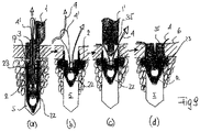
図1は本発明に係る装置の例示的実施例の遠位部を示し、断面としてツール1の遠位端、縫合アンカー2、およびインターフェイス片3を示す。さらに、縫合糸4が(一点鎖線で)示され、アンカー2を通ってループをなして延在し、縫合糸端部はインターフェイス片3およびツール1の部分を通る。示されている遠位装置部は、液化および固定処理の前(図1の左側)および後(図1の右側)における、硬組織開口5に対して位置づけられ、硬組織開口5はたとえば骨組織内の開口であり、骨表面6から皮質性骨層7を通って海綿骨組織8内に達する。
DESCRIPTION OF PREFERRED EMBODIMENTS FIG. 1 shows the distal portion of an exemplary embodiment of the device according to the present invention, showing the distal end of the
ツール1は、遠位端において遠位ツール面10と、遠位ツール面から軸方向に延在する軸方向チャネル11とを含む。軸方向チャネル11は第1の引っ掛かりエレメント12(たとえば楔形の突出部)と、第1の引っ掛かりエレメント12の近位方向において、軸方向チャネル11を終端させるまたは少なくとも部分的に閉鎖するストップ13とを含む。ストップ13は示されている例では、横凹部14の近位壁からなり、凹部は視認用に軸方向チャネル11を横方向に開口する。近位方向に横凹部14に隣接するツール部は、溝15を含み、溝15は縫合糸4を収容するための横凹部14と整合する。ツール1は好ましくは外段差16をさらに含み、これはより小さい断面を有するツール1の遠位端部17を、より大きい断面を有する近位方向において隣接する部分と分ける。図1に示されるように、段差16はツールの外周の一部のみ延在するだけで十分であるが、ツールの外周全体にわたって延在してもよい。
The
縫合アンカー2は、アンカー脚22および熱可塑性スリーブ23を含み、アンカー脚22および熱可塑性スリーブ23は別々の物体であっても、または一体的物体であってもよい。アンカー脚22はチャネルおよび/または溝の系統25を含み、その中を縫合糸4は好ましくは摺動可能なループをなして延在し、アンカー脚22の近位面を通って出る。図1に示されるように、チャネルおよび/または溝の系統は、たとえばアンカー脚軸に対して実質的に垂直に延在する横断第1チャネル30と、この第1のチャネル30の両方の入り口の領域において、凹部31または溝と、アンカー脚22の近位面に延在し、角度のついた第3のチャネル33を通って凹部31または溝に接続される軸方向の第2チャネル32とを含む。
The
二本以上の縫合糸4を収納するために、チャネルおよび/または溝の系統25は複数の横断第1チャネル30を含んでもよく、横断第1チャネル30は互いに軸方向に間隔があけられ、さらに互いに対して平行にまたは角度がついて配置される。
To accommodate two or
インターフェイス片3は実質的に管形状であり、熱可塑性スリーブ23を通ってゆとりを持って延在するよう設計されている。インターフェイス片は、アンカー脚22に対して遠位端で結合(または結合可能に)され、遠位スリーブ面がアンカー脚22の近位面上に乗った場合に、近位スリーブ面を越える。アンカー脚22およびインターフェイス片3の結合は、図示されるように管状アンカー脚突出部を介在して行なわれ、インターフェイス片3の遠位端部がたとえば圧入される。このような圧入結合の代わりに、それ自体既知であるクリップオン接続も適用可能であり、この場合、インターフェイス片3の遠位部は環状リッジを含み、管状アンカー脚突出部は、このリッジに適合される環状溝を含む。近位部において、インターフェイス片3は第2の引っ掛かりエレメント12′、たとえば凹所を含み、これはツール1の軸方向チャネル11にある第1の引っ掛かりエレメント12に適合され、以下に記載する態様でこの第1の引っ掛かりエレメント12と協働する。
The
縫合アンカー2はツール1の遠位端に配置され、インターフェイス片3の近位端はツール1の軸方向チャネル11内に延在し、アンカー脚22の近位面から延在する縫合糸4はインターフェイス片3を通ってツール1の凹部14に入り、そこから溝15に進む。熱可塑性スリーブ23は、それぞれの端部によって、または縫合糸4がツールの近位端で保持される(たとえば図4参照)ことにより、ツール1の遠位面10とアンカー脚22との間に保持される。インターフェイス片3、熱可塑性スリーブ23、および遠位方向において凹部14に隣接するツール部の軸方向の長さは、熱可塑性スリーブ23が最初の最大長さを有する場合に、インターフェイス片3の近位面が凹部14内において少し見えるほどになっている。ストップ13は、液化される熱可塑性スリーブ23の長さだけ、インターフェイス片3の近位面の上記の場所から離れている。引っ掛かりエレメント12および12′は、インターフェイス片3の近位面がストップ13に当接する前に互いに引っ掛かるように配置されており、協働する引っ掛かりエレメントは、ツールに対するインターフェイス片3の遠位方向の動きを制限し、それによりインターフェイス片はチャネル11から外れないが、場合によってはさらに近位方向に移動できる。
The
液化処理のために振動エネルギを用いる場合、ツール1の遠位面10(または熱可塑性スリーブ23の近位面)に対してエネルギディレクタを具備することは有利である。たとえばラインへの熱可塑性スリーブの接触を制限するエッジを有する、および/または熱可塑性スリーブ23の遠位面をアンカー脚22に剛性的に装着する。これはアンカー脚22が熱可塑性材からなる、たとえば熱可塑性スリーブ23が溶着できるPEEKからなる場合、容易である。さらに、アンカー脚および熱可塑性スリーブを、たとえばポリ乳酸だけからなる熱可塑性特性を有する材料(図11も参照)、たとえばPDLLA、好ましくは30%の二相性リン酸カルシウムで充填されたPDLLA70%/30%からなる、一体部分として作成することも可能である。上記の手段すべては、熱可塑性スリーブ23の液化をその近位面に限定することを確実にする。クリーピングの傾向があるポリマーからなるアンカー脚の場合、縫合糸の引っ張りによって最も負荷を受ける領域を強化するのが有利であり得る。これはたとえば横断縫合チャネル30をたとえば結晶化度がより高いポリ乳酸もしくはPEEKのようなより耐性のある材料からなる管を裏打ちすることにより、またはこのような材料の部分を横断縫合チャネル30に近接して位置づけることにより、達成される。
When using vibrational energy for the liquefaction process, it is advantageous to have an energy director for the
穴をあけることにより縫合アンカー2を係留するための硬組織開口5を設けることが最も便利であるので、アンカーと開口5内に位置づけられるツールの少なくとも遠位端部16とは、有利に円形の断面を有する。同じことが、アンカー脚22、インターフェイス片3および中を通る軸方向チャネル、ならびに熱可塑性スリーブ23およびツール1の軸方向チャネル11にも当てはまる。しかし、これは本発明の条件ではなく、上記の項目のいずれも円形でない断面を有してもよい。断面についての唯一の条件は、材料の十分な部分が開口5の壁近くにあるよう、開口5内に嵌合する熱可塑性スリーブ23に対する条件である。ツール1の遠位端部17の断面およびアンカー脚22の断面は、好ましくは熱可塑性スリーブ23の断面と同じである、または後者に対してわずかに小さい。
Since it is most convenient to provide a hard tissue opening 5 for anchoring the
縫合アンカー2を硬組織開口5内に固着し、それに伴って縫合糸4を硬組織面6に対して装着するために、本発明に係る装置は、図1の左側に示されるように、骨開口5に対して位置づけられる。エネルギ源はツール1の近位端(図示されていない)に結合され、インターフェイス片3およびアンカー2は遠位ツール端で配置され、縫合糸4はアンカー脚22、インターフェイス片3、ツール1の軸方向チャネル11および凹部14を通って延在し、かつ少なくとも真っ直ぐになるようにまたはわずかに引っ張られるようさらに近位方向に保持され、それにより熱可塑性スリーブ23はツール1の近位面10とアンカー脚22との間に保持され、ツール1は段差16が骨表面6に対して当接するよう位置づけられる。熱可塑性スリーブ23の液化を始めるために、エネルギ源が起動され、場合によっては縫合糸の引っ張りが増加される。液化した材料はアンカー2およびツール1から離れる半径方向に流れ、熱可塑性スリーブ23は短くなり、縫合糸4を近位方向に引っ張り、それによりアンカー脚22を遠位ツール面10に近い方向に引っ張ることにより、ツール1の遠位面10と接したままとなり、その間段差16は骨表面6と接触したままである。
In order to secure the
係留処理の原理は、たとえばUS−2009/131947に記載されている(異なる用途)。 The principle of mooring treatment is described for example in US-2009 / 131947 (different uses).
振動ツールと摩擦および/または熱感応縫合糸とを用いる場合、エネルギ源が起動したときに縫合糸に引っ張りを与えずに、熱可塑性スリーブの近位面が少なくとも温められた場合にのみ引っ張りを与えて、振動をさらに遠位にまたは少なくともすべてを伝達できないようにすることが重要である。縫合糸が振動の始まった瞬間引っ張られると、振動が熱可塑性スリーブを通ってアンカー脚に伝達され、これが縫合糸に対して振動することになり得る。これは熱可塑性スリーブの液化が始まる前に繊細な縫合糸に損傷を与えるかもしれない。アンカー脚への振動伝達を防止するための他の手段としては、上記のように、ツール1と熱可塑性スリーブとの間の界面でのエネルギダイレクタがあり、および/またはより小さい開始振幅で振動を始めて熱可塑性スリーブの近位端が加熱する開始期間後に振幅を増加させることもできる。
When using an oscillating tool and friction and / or heat sensitive sutures, pull only when the proximal surface of the thermoplastic sleeve is at least warmed without pulling the suture when the energy source is activated. Thus, it is important that vibrations cannot be transmitted further distally or at least all. When the suture is pulled the moment vibration begins, vibration is transmitted through the thermoplastic sleeve to the anchor leg, which can vibrate against the suture. This may damage delicate sutures before the liquefaction of the thermoplastic sleeve begins. Other means for preventing vibration transmission to the anchor legs include an energy director at the interface between the
液化処理が進行し、熱可塑性スリーブ23が短くなり、アンカー脚22が近位方向に引っ張られると、引っ掛かりエレメント12および12′が互いに対して引き止める相互作用に達して、インターフェイス片の近位面がストップ13に当接するまで、インターフェイス片3は凹部14の軸方向チャネル11内で進み、当接は図1の右側に示されるように、液化処理の終了を示す。インターフェイス片3の近位端の進行およびそれに伴う液化処理は、凹部14内において視覚的に制御できる。
As the liquefaction process proceeds, the
液化処理の終わりにおいて、熱可塑性スリーブ23の軸方向の長さは最小となり、熱可塑性スリーブ23の液化されて再固化された材料40は、半径方向に海綿骨8内に延在し、および/または縫合アンカー2を皮質性骨層7の内側にしっかりと係留する。さらに、インターフェイス片3はツール1の軸方向チャネル11に引っ掛かり、これによりツール1を係留された縫合アンカーから外す場合、インターフェイス片3もツール1とともに外されることを意味する。
At the end of the liquefaction process, the axial length of the
インターフェイス片の近位面がストップ13に当接したときに、縫合糸4がインターフェイス片3の近位端とストップ13との間で挟まれないようにするためには、ストップに対するインターフェイス片3の当接は凹部14の底面においてのみ起こり、その間縫合糸4はこの底面から離される、すなわち凹部14の開口に向かって引っ張られるよう、近位面および/またはストップ13の傾斜を設計することが有利である。インターフェイス片3の近位面の上記の形状は、インターフェイス片3の近位面の当接部の弾性を容易にし、これは第2の引っ掛かりエレメント12′の設計にも用いることができる。
In order to prevent the
液化処理が完了した後、縫合糸4は引っ張られて保持される状態から解放され、ツール1はインターフェイス片3と共に、縫合アンカー2がしっかりと係留されている開口5から外され、縫合糸は骨組織に対して摺動可能に取り付けられている。
After the liquefaction process is complete, the
図2は図1に示される方法の結果を示す。すなわち、硬組織にある、または開口の周りにある骨組織、特に皮質性骨層7のすぐ下にある海綿骨組織8にある再固化材料40によって硬組織開口5内に係留された(皮質下固定)縫合アンカー2を用いて、縫合糸4は硬組織に取り付けられ、再固化材料40は熱可塑性スリーブ23の残りの部分に接続されている。明らかに、本発明に係る固着処理は、まったく存在しないこともあり得る海綿骨8の品質に依存しない。海綿骨8がない場合、液化材料は皮質性骨層の内面に浸透するまたは浸透しなくてもよく、再固化後では、もはや開口を通過することができない本体をなすことにより、硬組織開口内に保持される。これは、本発明に係る固着は物理的安定性が減少した海綿骨における皮質下固着だけではなく、海綿骨がない場合、たとえば長い骨の骨髄腔内において、または骨プレートのアクセスできない側での固着も可能となる。
FIG. 2 shows the results of the method shown in FIG. That is, anchored in the hard tissue opening 5 by the
図3は、本発明に係る装置の、引っ掛かり機構およびツール1とインターフェイス片3との間のストップ機構の代替実施例を示す図である。ここでもツールは軸方向チャネル11を含み、軸方向チャネル11は遠位ツール部を少なくとも延在し、その中を実質的に管状のインターフェイス片3が延在し、ツールは凹部14を含み、凹部14の中にインターフェイス片3の近位端が液化処理の際近位方向に動く。第1の引っ掛かりエレメント12は、凹部14の遠位側においてツール面によって構成され、第2の引っ掛かりエレメント12′は、インターフェイス片3の近位突出部上に配置される。2つの引っ掛かりエレメントにより、熱可塑性スリーブが元の(最大)長さを有する場合でも、インターフェイス片3がツールの軸方向チャネル11内に保持されることを維持する。つまり、熱可塑性スリーブおよびアンカー脚を取り付けるために、ツールから外されたインターフェイス片は、装置を固定プロシージャ用に準備するために、インターフェイス片の近位端を軸方向チャネル内に導入すると、既に軸方向ツールチャネル11内に保持されている状態にあることを意味する。熱可塑性スリーブの材料の液化の際、第2の引っ掛かりエレメント12′は第1の引っ掛かりエレメント12に対して近位方向に離れており、ツール1およびインターフェイス片3を固定箇所から外す場合、インターフェイス片3はその最も遠位位置に変位され、そこで2つの引っ掛かりエレメントが互いに接する。
FIG. 3 shows an alternative embodiment of the catch mechanism and the stop mechanism between the
図3に係るツールのストップ13は、凹部14内において段差として配置され、インターフェイス片3の近位面の一部と相互作用し、その部分は第2の引っ掛かりエレメント12′の突出部とほぼ対向する。インターフェイス片3用のストップ13を設けなくてもよい可能性も十分ある。このような場合、インターフェイス片3およびアンカー脚の近位方向の動きは最後に終わることになり、つまり熱可塑性スリーブ23が完全に液化され、アンカー脚が遠位ツール面に当接した場合に終わる。さらに、縫合糸の引っ張りによって、液化処理を制限することも可能であり、これはたとえば図4と関連して説明されるレバーシステムを用いて行なわれる。
The
本発明に係る方法および装置は、図7と関連して以下でより詳細に説明されるそれ自体既知であるダブルロープロシージャにおいて、さらにローテータカフ修復またはアキレス腱修復のために用いられる中間アンカーを展開するために適する。この用途では、縫合糸はアンカーに対して摺動可能に保たれる。本発明に係る方法および装置の他の例示的適用例は、たとえばヒトの肩関節については、バンカート修復またはSLAP損傷(上方関節唇)の修復があり、ヒトの手については、UCL修復(尺骨側副靭帯)、SL修復(舟状月状靭帯)、副靭帯の修復、屈筋腱の再付着、中手指節関節の莢膜の再付着、およびヒトの足については、ブロムストローム靭帯の修復、内側嚢縫合術の外反母趾の治療、または腓骨支帯修復がある。 The method and apparatus according to the present invention further deploys an intermediate anchor used for rotator cuff repair or Achilles tendon repair in a double row procedure known per se, described in more detail below in connection with FIG. Suitable for. In this application, the suture is kept slidable relative to the anchor. Other exemplary applications of the method and apparatus according to the present invention include bankart repair or SLAP injury (upper joint lip) repair for human shoulder joints and UCL repair (ulna for human hands), for example. Collateral ligament), SL repair (scaphoid ligament), collateral ligament repair, flexor tendon reattachment, metacarpophalangeal joint reattachment, and for human foot, bromstrom ligament repair, Treatment of hallux valgus with medial sac suture, or repair of the rib brachia.
図1から図3に示される、本発明に係る装置の遠位端およびこのような装置を用いて行なうことができる固着方法は、本発明の基本的概念から逸脱することなく、たとえば以下の態様で変形することができる:
・図示されている引っ掛かりエレメント12および12′の代わりに、それ自体既知である引っ掛かりエレメントの対を用いることができ、これは少なくとも固着処理の際、ツール1とインターフェイス片3との摩擦ができるだけ低く、および/またはツール1の軸方向チャネル11内におけるインターフェイス片3の最後の部分の進行の間だけに起こるよう、引っ掛かりエレメントを設計する。
The distal end of the device according to the invention and the fixing method that can be carried out using such a device as shown in FIGS. 1 to 3 are, for example, the following embodiments without departing from the basic concept of the invention: Can be transformed with:
Instead of the illustrated catching
・横凹部14の代わりに、ツール1はシースルー部を含むことができ、これによりツール1の軸方向チャネル11内におけるインターフェイス片3の近位端の動きを視覚的に確認することができ、縫合糸4は別の開口を通って、または遠位ツール面から少なくともストップ13に延在するスロットを通って、外に延在する。
Instead of the lateral recess 14, the
・ツールは、視覚的確認のための手段を含まない。
・凹部14は狭く、遠位ツール面まで延在し、インターフェイス片3は固着処理を視覚的に制御するために、凹部内に延在し、かつ場合によっては凹部から突出してツール1の外部から見ることができるフラグを含む。
• The tool does not include means for visual confirmation.
The recess 14 is narrow and extends to the distal tool surface, and the
・ストップ13の軸方向位置は、異なる軸方向の位置で凹部14内に固定することができる別個のストップエレメントとしてストップを設計することにより選択可能であり、または凹部14内に固定することができる、異なる軸方向の長さを有する別個のストップエレメントの選択として設計することにより、選択可能である。
The axial position of the
・縫合糸4をアンカー脚22の遠位領域に保持するチャネルおよび/または溝の系統25の代わりに、アンカー脚は近位面から突出する糸穴、または縫合糸4を摺動可能な態様で保持するための他の適切な近位手段を含む。
Instead of a channel and / or
・縫合糸4は摺動不可能態様でアンカー脚22内に保持され、これは縫合糸が近位方向に延在する近位方向に隣接するチャネルよりも大きい断面を有する遠位凹部内に保持される結び目または縫合保持部を用いることによりなされる、またはアンカー脚22に形づくられる縫合糸端またはループによって保持される。
The
・ツール1は、硬組織開口5内に嵌合するよう適合された断面を有する遠位ツール部17の軸方向を制限する段差16を含まない、または段差16はさらなる近位位置を有する。これは、遠位ツール端が外科医によって選択される深さまで硬組織開口5内に挿入できること、または遠位ツール端は硬組織開口内に挿入されて、固着処理が開始されるときにはこの開口の底面に達することを意味する。固着処理の際、遠位ツール端は熱可塑性スリーブが液化によりさらに短くなる間、硬組織開口内により深く移動することができ、アンカー脚22は硬組織開口5の底面に対して位置づけられたまま残る。図1に関連して前に記載した以外では、このような場合、液化工程の際には、熱可塑性スリーブ23を振動ツールに対して保持するのは張力がかけられた縫合糸ではなく、さらにツールを支持するのは骨表面6ではなく、これら機能の両方は、硬組織開口の底面によってその役目が引き継がれる。これは、底面の骨組織が対応する物理的強度を持たなければならないことを意味し、縫合糸の必要な物理的強度はこの縫合糸の組織接続機能のみに適合する必要がある。
The
・アンカー脚22は、前もって開口を設ける必要なく、または中皮質骨だけを通る開口を設ける必要なく、少なくとも海綿骨に押し込むことができるよう、たとえばテーパー状の、または鋭くなった遠位端を有することにより適合される。骨組織へのアンカー脚22の押し込みは、図1に示されるように、アンカー脚22を遠位ツール端に配置することにより、さらにツール1に対応する力を与えることにより行なわれ、この力は熱可塑性スリーブ23を介してアンカー脚22に伝えられる。液化処理は、アンカー脚22が骨組織の所望な深さに達した場合にのみ、エネルギ源(たとえば、振動源)の起動によって始まる。骨組織内にアンカー脚22を押し込むことが振動エネルギを伴うものなら、熱可塑性23を介したツール1からアンカー脚22への押し込み力および振動の伝達は、この押し込み工程の際に熱可塑性スリーブ23が不所望に液化するのを防ぐために、防止されなければならない。これはインターフェイス片3を介して力および振動をアンカー脚に伝達し、熱可塑性スリーブ23は遠位ツール面とアンカー脚との間でゆとりを持たせて配置されることを確実にすることによって実施される。たとえば、インターフェイス片の近位方向の移動を防止し、振動および力をツール1からインターフェイス片に伝達することができるブロックエレメントを凹部14内に組み込むことによって実施される。ブロックエレメントは、固着工程には除去される。
・アンカー脚22は、前もって開口を設けずに、たとえば尖がったまたは他の態様で鋭い遠位端を有することにより、硬組織(少なくとも海綿骨組織)内に押し込むことができるよう具備され、たとえば超音波振動を用いて硬組織内に押し込まれ、必要な押し込み力および振動をアンカー脚22に伝えるために、インターフェイス片3または他の適切な押し出しツールが用いられる。熱可塑性スリーブは、アンカー脚に固定されるまたは固定されないかのどちらかである。アンカー脚が所望の深さに到達し、さらに適用可能であるのなら、押し込みツールを外してインターフェイス片3をアンカー脚22に取り付けた後、さらに適用可能であるのなら熱可塑性スリーブ23を取り付けた後、ツール1の遠位端は熱可塑性スリーブの近位面に位置づけられ、固着工程は図1に関連して前に記載したとおり実施される。アンカー脚を硬組織内に押し込む代わりに、アンカー脚を硬組織内に螺合することもでき、ここではインターフェイス片3または他の適切なツールを用いてねじ形状のアンカー脚に回転を与える。
The
図4は、たとえば図1から図3に関連して前に述べたように、遠位端を有する装置の例示的実施例の近位端部を示す。この近位端部は軸方向の断面が示され、ハウジング51内に配置されるエネルギ源50(好ましくは、超音波振動ジェネレータ)に結合されるツール1の近位端と、縫合糸4の2つの端部(一点鎖線)とを含む。装置の近位端部はさらに、縫合糸4を固定および真っ直ぐにするおよび/または引っ張るための手段として働く、さらにアンカー脚を通って延在する縫合糸4(図1に示される)を用いて、ツール1に対して近位方向にアンカー脚を動かすための手段として働く、レバーシステム52をさらに含む。レバーシステム52は好ましくはエネルギ源50のハウジング51上に配置されるが、エネルギ源上に、またはツール1の近位部上にも配置できる。レバーシステム52は、外科医によって操作されるよう意図されている。
FIG. 4 shows the proximal end of an exemplary embodiment of a device having a distal end, for example as previously described in connection with FIGS. This proximal end is shown in an axial cross-section, the proximal end of the
図4において、装置の近位部、特に上記のレバーシステム52は、3つの構成(a)、(b)および(c)で図示され、1つの固定処理について連続したものとなる。構成(a)は、縫合糸4の端部をレバーシステム内に導入することに対応する。構成(b)では、縫合糸の端部はレバーシステム内において挟まれるまたは制動される(小さい半径の周りに沿って少なくとも1つ曲げる)ことにより固定され、構成(c)では、縫合糸4の固定された端部は、半径方向におよびツール1に対して近位方向に動かされ、それにより縫合糸を真っ直ぐにするまたは張力をかけ、熱可塑性スリーブの液化が始まると直ちにアンカー脚(図1参照)をツールに対して動かす。
In FIG. 4, the proximal portion of the device, in particular the lever system 52 described above, is illustrated in three configurations (a), (b) and (c) and is continuous for one fixation process. Configuration (a) corresponds to introducing the end of the
図4に示されるレバーシステム52の例示的実施例は、クランピングアーム53および引っ張りアーム54を含む。クランピングアーム53は枢支運動する態様でハウジング51上に配置され、引っ張りアーム54は、クランピングアーム53の自由端に対して連接する態様で接続される。引っ張りアーム54はクランピングアーム53よりも長く、システムを手により起動するのに適切な端部が有利に備わっている(図示されていない)。レバーシステム52の各アーム53および54は、縫合糸を2つのアームの間に固定するための手段を含む。たとえばアーム53および54が互いに対して回動して、実質的に同じ方向でその連接する接続から延在したときに、縫合糸端部を互いの間に挟むよう配置されている1対のクランピングジョー55を含む。アームはこの固定した位置で互いに係留(たとえば、スナップ接続)するよう、さらに具備されており、接続機能はクランピングジョー55に統合されてもよい。
The exemplary embodiment of the lever system 52 shown in FIG. 4 includes a clamping
図4は、図1に関連して既に説明した溝15も示し、溝15は好ましくはツールの近位端まで達し、縫合糸4を収納する働きがあり、溝15およびレバーシステム52は互いに対して整合される。図4はさらに、溝15とレバーシステム52との間に配置される縫合糸ガイド56を示す。
FIG. 4 also shows the
縫合糸4の端部をレバーシステムに固定し、縫合糸4を真っ直ぐにするまたは引っ張り、縫合糸を用いてアンカー脚を動かすことは、以下の態様で行なわれる。レバーシステム52によって縫合糸4の端部を通過させるために、2つのアームは実質的に延び切った位置にされ、有利に遠位方向に延びる(構成(a))。溝15内を走る、または溝が設けられていない場合には、近位ツール端に向かってツール1に沿って走る、縫合糸4の端部は、縫合ガイド56および糸穴57を通過し、アーム53および54の一方を通ってアームの一方(外)側に達し、このアームの構成では、ツール1から反対方向に向く。縫合糸の端は引っ張りアーム54の外側にある付加的糸穴58を通り、2つの糸穴57および58によって案内されて、引っ張りアーム54のクランピングジョー55を通って延在する。縫合糸4の端部は、引っ張りアーム54の自由端で保持され、真っ直ぐに延在するが、記載されている経路(矢印T、構成(a))に沿ってはほとんど引っ張られない。引っ張りアーム54はクランピングアーム53に対して回動し、その間縫合糸4の端部は、縫合糸4がクランピングジョー55の間に挟まれるまで、引っ張りアーム54の自由端で保持され、アーム53および54が互いにクランピング位置で係止される(構成(b))。この構成状態において、装置はチェックされ、場合によってはエネルギ源を短く動かすことにより調整される。このようなチェックおよび場合によっては調整の後、装置は縫合アンカーを植え込む準備ができている。
The end of the
このようなインプランテーションの際、引っ張りアーム54の自由端をハウジング51に対して引っ張ることにより、縫合糸4に張力がかかり、それにより縫合糸端部が固定されている他方端がハウジング51から離れて、かつ近位方向に動き、エネルギ源50は起動されて液化が始まる。液化処理の際、引っ張りアーム54への圧力(構成(c)の矢印P)が保持され、このように動かされた引っ張りアーム54の自由端はハウジング51にさらに近づく、またはその他方端はハウジング51からさらに遠ざかり、それによりアンカー脚を近位方向に動かす(構成(c))。
During such implantation, the
図4に示されるレバーシステム52は、縫合糸の引っ張りを制御する、および液化処理またはアンカー脚の近位方向の動きを制御するための手段をそれぞれ含んでもよい。縫合糸が最初に通されてレバーシステムで固定された場合に、縫合糸の引っ張りを最小にする、または真っ直ぐな縫合糸の伸びを確実にするために、ローラ59を弾性的態様(たとえば、ばねを介して)糸穴56および57の間でハウジング51に装着することができる。縫合糸がローラ59の周りを通ると、ローラはばねによって糸穴から離れる方向に動かされることにより、縫合糸のたるみをなくす。縫合糸を引っ張るためにレバーシステムを起動させると、ローラ59は2つの糸穴と整合する最も伸びた位置に動かされる。ローラ59の固着の際の弾性は、図示されるように引っ張りばねを用いて得ることができるが、圧縮ばねまたは他のそれ自体既知である手段(たとえば、機械的、空気圧的または油圧的手段)を用いても得ることができ、これは縫合糸のたるみをなくして縫合糸の引っ張りをほぼ一定に保つだけでなく、縫合糸を損なうかもしれない振動もしくは衝撃を吸収する役割を果たす。 The lever system 52 shown in FIG. 4 may each include means for controlling suture pull and for controlling the liquefaction process or the proximal movement of the anchor leg. In order to minimize suture pull or ensure straight suture stretch when the suture is first threaded and secured with a lever system, the roller 59 is elastically configured (e.g., spring Can be attached to the housing 51 between the thread holes 56 and 57. As the suture passes around the roller 59, the roller is moved away from the thread hole by the spring, thereby eliminating slack in the suture. When the lever system is activated to pull the suture, the roller 59 is moved to the most extended position aligned with the two thread holes. The elasticity at the time of fixing of the roller 59 can be obtained using a tension spring as shown, but is a compression spring or other means known per se (eg mechanical, pneumatic or hydraulic means). Can also be obtained, which not only eliminates the slack in the suture and keeps the suture tension nearly constant, but also serves to absorb vibrations or shocks that may damage the suture.
レバーシステム52は、図1および図3に関連して説明したように、ストップの機能を引き受けることもでき、これは最も簡単な場合は、アンカー脚が所望の最近位位置に達したときに、ハウジングに当接することによって可能である。液化処理およびその所望の端部は、縫合糸引っ張りによって制御することもできる。これは、引っ張りアームの近位部が弾力性を有するように設計することにより得られ、そのおかげで所望の最大力だけで縫合糸を引っ張り可能であり、より大きな力が与えられた場合には曲がるだけである。液化処理を制御するこの手段は、熱可塑性スリーブがなくなった場合に処理を停止させるだけでなく、液化材料によって浸透するべき硬組織の容量が一杯となり、不所望な大きさの力でしかさらに材料を組織内に押し込むことができない場合に処理を停止させることが可能となる。後者の場合、液化処理は引っ張りを受ける縫合糸の延在と独立して制御され、アンカーが固着される硬組織に依存して制御できることを意味する。さらに、縫合糸の引っ張りの制限、たとえば上記の態様での制限により、縫合糸が固着処理の際損なわれないことを確実にする。 The lever system 52 can also assume the function of a stop, as described in connection with FIGS. 1 and 3, which in the simplest case is when the anchor leg has reached the desired proximal position. This is possible by contacting the housing. The liquefaction process and its desired end can also be controlled by suture pull. This is obtained by designing the proximal portion of the pull arm to be elastic, so that the suture can be pulled with only the desired maximum force, if more force is applied. It just turns. This means of controlling the liquefaction process not only stops the process when the thermoplastic sleeve is exhausted, but also fills the volume of hard tissue to be infiltrated by the liquefied material, and more material with an undesirably large force. When it is not possible to push into the tissue, the process can be stopped. In the latter case, the liquefaction process is controlled independently of the extension of the suture undergoing tension, meaning that it can be controlled depending on the hard tissue to which the anchor is secured. Furthermore, limitations on suture pull, such as the limitations in the above-described manner, ensure that the suture is not impaired during the anchoring process.
図5は、レバーシステムに縫合糸を固定するための手段ならびにクランピングアーム53および引っ張りアーム54をクランピング位置に係止するための手段のさらなる例示的実施例を示す。同様の要素は、図4と同じ参照符号が付けられている。図4に示されるクランピングジョー55の代わりに、2つのアーム53および54はクランピング位置にある場合に、緩みを持たせて噛み合う協働する湾曲プロファイル55.1を含む。湾曲プロファイルは、プロファイル間の間隙を通る縫合糸の動きを防止するために、2つのプロファイル間を通る縫合糸を十分に制動するだけの十分な数の湾曲および/または十分に小さい半径を有する。図5の固定手段の利点は、縫合糸が挟まれてそれにより断面については変形する必要がないことであり、挟まれることは繊細な種類の場合には縫合糸を損傷するかもしれない。
FIG. 5 shows a further exemplary embodiment of means for securing the suture to the lever system and means for locking the clamping
図5に示されるようなクランピング位置にクランピングアーム53および引っ張りアーム54を係止するための手段は、スナップ接続55.2であり、引っ張りアーム54上に突出部とクランピングアーム53に対応する凹所とを含み、この突出部は凹所内に嵌め込まれるよう十分に弾力性を有する。
The means for locking the clamping
上記のレバーシステム52の代わりに、本装置はラチェット機構またはたとえばハウジング51の表面に対して変位される簡単な爪を含んでもよく、これにより縫合糸端部をこの表面に対して挟み、縫合糸が一方向にのみ動くよう設計されている。または、装置は縫合糸4を固定、真っ直ぐにするまたは引っ張り、縫合糸の引っ張りを維持しながら縫合糸を用いてアンカー脚の動きを可能にする他の既知の機構を含んでもよく、外科医は縫合糸端部を引っ張ることによりその機構を操作する、またはその機構は外科医が取り扱う部材を含む。本装置の非常に簡単な実施例では、装着、引っ張り、および動かすためのこのような手段はなく、外科医が縫合糸を持って張力をかけ、それに伴ってアンカー脚を動かすことになる。
Instead of the lever system 52 described above, the device may include a ratchet mechanism or a simple claw that is displaced relative to the surface of the housing 51, for example, thereby pinching the suture end against this surface and Is designed to move in only one direction. Alternatively, the device may include other known mechanisms that allow the anchor leg to be moved using the suture while securing, straightening or pulling the
図6は、上記の方法であって、縫合アンカーが硬組織開口を越えて、すなわち硬組織層のアクセスできない側の空洞または軟組織(たとえば、長い骨の骨髄腔、海綿骨組織がない皮質性骨層下の場所、または骨プレートもしくは骨プレートに置き換わるプロテーゼのアクセスできない側)に固着するための方法に向けられる。図6に示される装置は、図1および図3に示される装置の簡略化されたものである。 FIG. 6 shows a method as described above, wherein the suture anchor extends beyond the hard tissue opening, i.e. the cavity or soft tissue on the inaccessible side of the hard tissue layer (e.g. long bone marrow cavity, cortical bone without cancellous bone tissue). It is directed to a method for adhering to an underlayer location, or to a bone plate or an inaccessible side of a prosthesis that replaces a bone plate. The apparatus shown in FIG. 6 is a simplified version of the apparatus shown in FIGS.
縫合アンカー2を固着するために設けられた開口はいわゆる上皮質固着であり、縫合アンカーを固着するために設けられた硬組織開口は硬組織内(たとえば、皮質性骨層下の海綿骨組織)に達するのではなく、骨41のアクセス可能側42からアクセスできない側43に達するものであり、皮質下アンカレッジの代わりに上皮質ボタン44が形成される。この上皮質ボタン44は、骨のアクセス可能でない側の表面に係留されてもまたは係留されなくてもよい。この固着が行なわれる方法は、図1から図5に関連して記載されたものと類似している。
The opening provided for fixing the
本装置の簡略化された実施例において、縫合アンカー2はアンカー脚22および熱可塑性スリーブ23を含み、縫合糸4のループはアンカー脚(チャネルおよび/または溝の系統25)において好ましくは摺動可能であり、縫合糸の端部は熱可塑性スリーブ23およびツール1の遠位部17を通る。遠位ツール部17は軸方向チャネル11を含み、その軸方向の長さは、段差16の対応する位置により、骨41の厚さとほぼ等しいよう決定される。特に、相対的に短い熱可塑性スリーブ23を用いる場合、図1および図3に示されるインターフェイス片を使用しなくてもよい。熱可塑性スリーブ23の遠位面をアンカー脚22に固定することにより、またはツール1の遠位面10もしくは熱可塑性スリーブ23の近位面にエネルギディレクタを設けることにより、熱可塑性スリーブの近位端での好ましい液化が引き起こされる。
In a simplified embodiment of the device, the
固着処理の後でも縫合糸4がアンカー脚22および上皮質ボタン44によってまだ摺動可能に保持されていなければならないなら、熱可塑性スリーブ23の挿管内に達し、かつ上皮質ボタン44の最終厚さ以上の軸方向長さを有する管状近位突出部(図示されていない)をアンカー脚22に設けること、および/または図1および図3に示されるようなインターフェイス片を用いることが好ましい。縫合糸の摺動可能性が重要でない場合、アンカー脚22は図示されているように平坦であってもよく、インターフェイス片も省略することができる。このように、縫合糸は熱可塑性スリーブ23の液化材料によって係止されるまたは係止されなくてもよい。
If the
明らかに、図6に示される方法では、図1および図2に関連して説明したように、スリーブ材が開口の壁に近接するよう、熱可塑性スリーブ23の断面を硬組織開口5の断面に適合させる必要はない。必要なのは、アンカー脚22、熱可塑性スリーブ23、および好ましくはツール1の遠位端が開口5内に嵌合して、そこを通り、開口5を通過できないだけの十分な量のスリーブ材本体44をもたらすことである。
Obviously, in the method shown in FIG. 6, the cross section of the
上記のようにもたらされた上皮質ボタン44の例示的適用例は、たとえばヒトの肩については、急性肩鎖関節安定化、およびヒトの足については、靭帯結合損傷の固定化を含む。この適用例では、上皮質ボタンによって固着された縫合糸4は、腱または靭帯と直接置き換わることになる縫合糸の束であり得る。
Exemplary applications of the
図7は、軟組織を硬組織に縫合するためのそれ自体既知のダブルロープロシージャを示し、4つの連続するフェーズ(a)、(b)、(c)および(d)で、破れたローテータカフ腱60をヒトの骨組織61(または対応する体内プロテーゼ)に再付着する例に基づいている。フェーズ(a)は修復手術の前のものであり、再付着が必要な場所62を示す。フェーズ(b)では、2つの中間アンカー63が骨組織に固着され、その場所は最終的には腱60の下にあり、各中間アンカー63は少なくとも1本の縫合糸4を摺動可能な態様で骨組織に装着する。フェーズ(c)では、一方の中間アンカーに取り付けられる各縫合糸の端部が破れた腱60を通され、縫合糸を腱の端(図示されていない)から離れる方向に張力をかけることにより、後者は中間アンカー63上に引っ張られる。フェーズ(d)では、2本の横アンカー64が、破れのエッジを越えた骨組織に固定され、横アンカー64の列は中間アンカー63の列にほぼ平行に走り、縫合糸4の端部は引っ張られ、横アンカー64を用いて横方向に係止され、それにより1本の中間アンカー63によって保持される縫合糸の2つの端部は2つの異なる横アンカー64によって係止され、中間アンカー63の列と横アンカー64の列との間に横切る縫合糸ブリッジ65を形成する。
FIG. 7 shows a double row procedure known per se for suturing soft tissue to hard tissue, with a torn rotator cuff tendon in four successive phases (a), (b), (c) and (d) Based on the example of reattaching 60 to human bone tissue 61 (or corresponding endoprosthesis). Phase (a) is before the repair operation and shows the location 62 where reattachment is needed. In phase (b), two
中間アンカー63を展開するために本発明に係る方法および装置が用いられているダブルロープロシージャの場合では、熱可塑性特性を有する材料のin situの液化に基づく固着技術または上記のような類似したアンカーであって縫合糸係止向けに具備されているアンカー(たとえば図8および図9参照)を用いた横アンカー列を確立するのが有利であり、アンカーの各列は2つ以上のアンカーを含むことができ、各中間アンカー63は少なくとも1つの縫合糸4(2つの縫合糸端部)を装着するために用いられ、各横アンカー64は2つの異なる中間アンカー63から出てくる少なくとも2つの縫合糸端部を係止するために用いられる。
In the case of a double row procedure in which the method and apparatus according to the invention are used to deploy an
図8および図9は前に簡単に述べたダブルロープロシージャにおいて、たとえば横アンカーを固定するために用いられる装置および方法を図示し、縫合糸を摺動可能な態様で保持する縫合アンカーは上記の方法に従い、まず骨組織に固着され、次に縫合糸は付加的工程において縫合アンカーに対して係止することにより、結び目の必要をなくす。図8および図9に示される実施例は、このような縫合糸係止が必要な他の用途でも適用可能である。 FIGS. 8 and 9 illustrate the apparatus and method used in the above-described double row procedure, for example, to secure a transverse anchor, wherein the suture anchor holding the suture in a slidable manner is as described above. According to the method, the suture is first anchored to the bone tissue and then the suture is locked to the suture anchor in an additional step, thereby eliminating the need for a knot. The embodiment shown in FIGS. 8 and 9 is applicable to other applications where such suture locks are required.
図8は図2と同じ固着アンカーを示し、図1に示される固着処理後の縫合糸は、アンカーに対して摺動可能であり、固着工程の後の係止工程においてアンカーに係止され、この2工程のプロシージャにより、固着工程が終わった後でも縫合糸に張力がかかることを可能にする。係止工程において、プラグ35がアンカー脚22の軸方向チャネル32の近位口内に押し込まれて好ましくは溶着され、そこで縫合糸はプラグ35とアンカー脚22との間で挟まれることにより最初は係止される、または最初は溶着プロシージャによって、またはこの2つの組み合せによって、係止される。プラグ35は、縫合糸が骨組織に対して最終的に係止する必要があれば直ちに位置づけられて固定される。アンカー脚に溶着するためには、プラグ35およびアンカー脚22の各々は熱可塑性材を含み、2つの熱可塑性材は適切な振動ツール(図示されていない)をプラグ35の近位面に与えることにより、プラグ35に結合される好ましくは超音波振動エネルギを用いて互いに溶着される。熱可塑性プラグ35をチャネル32の粗面化または他に適する構造化された内面と合わせて、または熱可塑性アンカー脚22を粗面化または他に適する構造化された円周プラグ面と合わせて、さらにたとえば超音波振動エネルギをプラグに与えて、同時にプラグをチャネル32内に押し込むことによって、プラグ35をアンカー脚22に固定することもできる。プラグ35をアンカー脚22に装着し、それに伴い縫合糸をアンカー脚に対して係止する他の既知の方法も可能である。
FIG. 8 shows the same anchor as in FIG. 2, and the suture after the anchoring process shown in FIG. 1 is slidable with respect to the anchor, and is locked to the anchor in the anchoring step after the anchoring step. This two-step procedure allows the suture to be tensioned even after the anchoring step is over. In the locking process, the
図9は縫合糸固着のさらなる例示的実施例を4つの連続するフェーズ(a)から(d)で示し、アンカー脚22および熱可塑性スリーブ23を含む縫合アンカー2(たとえば、熱可塑性特性を有する一つの材料だけからなる一体型アンカー)は、たとえば図1に関連して説明された装置および方法を用いて、脚22の中を通された補助(または代替)縫合糸4′のループで硬組織開口5内に固定され、この補助縫合糸ループ4′は本発明に係る固着の際に縫合機能の役割を果たし、固着されたアンカー2に対して摺動可能である。フェーズ(a)において、アンカー2、補助縫合糸4′、ツール1、およびインターフェイス片3は、図1の左側に示されるような態様で係留する処理向けに位置づけられる。フェーズ(b)では、図2に示される同様の態様で、係留処理の後かつツール1およびインターフェイス片3を除去した後のアンカー2が示される。フェーズ(b)は外科用の機能(たとえばダブルロープロシージャで係留される中間アンカーから延在する縫合糸対)を示し、骨組織に対する係止を必要とする縫合糸4を示す。縫合糸4は補助縫合糸4′のループによって通され、次に縫合ループ4′がアンカー脚から引き出されることにより、アンカー脚22の中を通過する。フェーズ(c)では、縫合糸4はアンカー脚22および固定するための係止プラグ35(たとえば、溶着、好ましくは超音波振動エネルギを用いる)を通り、アンカーの近位面、すなわち熱可塑性スリーブ23の残りの部分に固定される。係止プラグ35は熱可塑性スリーブ23の軸方向チャネルに有利に到達し、スリーブに固定されることにより、縫合糸4はアンカー2に対してしっかりと係止される。フェーズ(c)は係止ツール1′をも示し、係止プラグ35はツールの突出部およびプラグ35の近位面の凹所により、遠位端に装着される。フェーズ(d)では、プロシージャが終了する。すなわち、縫合糸4はアンカー2に対してまたは骨組織に対してしっかりと係止される。図8に関連して前に説明したように、縫合糸の有効な係止は、プラグ35と縫合アンカー2との間で縫合糸を機械的に挟むことにより、または両方を互いに溶着することにより、またはこの両方を組み合わせることにより、実施することができる。
FIG. 9 illustrates a further exemplary embodiment of suture anchoring in four successive phases (a) to (d), and includes a suture anchor 2 (eg, one having thermoplastic properties) that includes an
図9に示されるように、プラグ35がアンカーに固定された場合、骨表面6と面一であるよう、アンカー2およびプラグ35の寸法を決めることは有利である(しかし必ずしも必要ない)。骨開口内での付加的固着を得るために、ツール1の遠位端部17の寸法が骨開口5内にきっちりと嵌合するのではなく、骨開口の壁と遠位ツール端17との間に小さい間隙があるようにすることは有利であるが、必ずしも必要ない。熱可塑性スリーブ23の材料の液化の際、液化材はこの間隙内に押し込まれ、係止工程において係止プラグに溶着する。
As shown in FIG. 9, when the
図8に関連してすでに説明したように、図9の係止プラグは、超音波溶着により、熱可塑性スリーブ23の残りの部分に溶着可能である熱可塑性材からなる、または押圧および超音波振動により熱可塑性スリーブ内に押し込まれた場合に、熱可塑性スリーブの残りの部分と正嵌合接続を形成するのに適する非液化材および表面構造(粗面またはアンダーカット構造、たとえばねじ山)を含む。係止プラグ35をアンカー2に固定する他の既知の固定方法を用いることも当然可能であり、たとえば接着剤の塗布、熱的溶着、正嵌合接続をもたらすスナップ接続、もしくはねじ山により、またはこのような複数の固着方法の組み合せを用いることができる。
As already explained in connection with FIG. 8, the locking plug of FIG. 9 consists of a thermoplastic material that can be welded to the rest of the
ダブルロープロシージャで横のアンカー列を確立するために、図8および図9に示される縫合アンカーならびに固着および係止方法を用いることは、中間アンカーおよび横アンカーが実質的に同じ方法および同じツールを用いて固定化できるという利点がある。 Using the suture anchors and the anchoring and locking methods shown in FIGS. 8 and 9 to establish a horizontal anchor row in a double row procedure would make the middle anchor and the transverse anchor substantially the same method and the same tool. There is an advantage that it can be used and fixed.
図10は本発明に係る方法についてさらなる付加的ステップを示し、この付加的ステップは縫合糸4が引っ張られたときに骨開口5の入り口の周りの硬組織エッジによって損傷しないように、および/または上記のエッジが縫合糸により損傷しないよう保護する働きがある。図10に示される固着されたアンカー2は、図2に示される固着されたアンカーと同じである。この保護ステップにおいて、保護スリーブ36は係止プラグ35について図9に関連して説明した態様と実質的に同じ態様で、熱可塑性スリーブ23の残りの部分に固着され、縫合糸4は保護スリーブ36を通って緩みを持たせて延在し、保護スリーブ36はアンカー2に固定されたときに、骨表面6と実質的に面一となる、または骨表面6からわずかに突出するよう、有利に寸法決めされる。
FIG. 10 shows a further additional step for the method according to the invention so that this additional step is not damaged by the hard tissue edge around the entrance of the
図11は、アンカー脚22および熱可塑性スリーブ23を含み、本発明に係る装置および方法に適する縫合アンカー2の軸方向の断面図である。図11に示される縫合アンカー2は好ましくは一体的物体であり、熱可塑性材を有する1つの材料だけからなり、本発明に係る方法の1つの特徴をなす、in situの液化に適する。アンカーは好ましくは生体再吸収可能である。このような一体的アンカーは(たとえば図9に関連して)既に説明した例示的アンカー実施例として言及され、たとえば30%の二相性リン酸カルシウムで充填されたPDLLA70%/30%からなり、ここではアンカー脚22は、熱可塑性スリーブ23の材料よりも多くの材料で充填される、または上記のように、たとえばより高い結晶度のポリ乳酸からなる、もしくはヒドロキシアパタイトからなる、縫合スリーブまたは強化エレメントを統合することにより、アンカー脚の材料を強化することが有利であり得る。
FIG. 11 is an axial cross-sectional view of a
図11に示される縫合アンカーは、長さがたとえば約15mmであり、約3から4mmの直径の円形断面を有し、熱可塑性スリーブ23の軸方向のチャンネルの直径は約2から3mmとなる。チャネルおよび/または溝の系統25は、図1に関連して記載したものとほぼ対応し、横断チャネル30、横凹部31、熱可塑性スリーブ23の軸方向チャネルと同軸である軸方向第2チャネル32、および凹部31を第2チャネル32に接続する角度のついた第3チャネル33を含む。2本の縫合糸を収容するために、2つ(または場合によって3つ以上)の平行な横断チャネル30をアンカーに備えることができ、これらのチャネルは互いに対して半径方向にまたは軸方向に離れている。
The suture anchor shown in FIG. 11 is about 15 mm in length, has a circular cross section with a diameter of about 3 to 4 mm, and the diameter of the axial channel of the
本発明は、本発明に係る装置および方法に特に適するが、振動エネルギ、特に超音波振動エネルギを用いて、特に低侵襲性手術の分野において、硬組織にインプラントを固着する分野で適用可能である振動ツール(ソノトロード)にも関する。当該振動ツールは、ロッド部と、ロッド部の近位端に装着される結合部とによって特徴づけられ、ロッド部の近位端は、好ましくは圧入接続により、結合部の軸方向のボア内に固定される。 The invention is particularly suitable for the device and method according to the invention, but is applicable in the field of fixing implants to hard tissue, particularly in the field of minimally invasive surgery, using vibrational energy, in particular ultrasonic vibrational energy. Also related to vibration tools (Sonotorodo). The vibration tool is characterized by a rod part and a coupling part attached to the proximal end of the rod part, the proximal end of the rod part being preferably in the axial bore of the coupling part by a press-fit connection. Fixed.
図12から図15は、振動ツール70の近位端の例示的実施例を示し、ロッド部71の近位端は、結合部72の軸方向のボア内に固定されている。図12は横方向の図であり、図13から図15はあり得る軸方向の断面図である。結合部72は結合手段、好ましくは振動源(図示されていない)に配置される結合手段と協働するよう設計されているねじ切りされたボルト73を含む。このような協働する結合手段は、差し込み結合またはできるだけ少ないエネルギで機械的振動を振動源からツールに伝達することができる類似した結合部用に設計され得る。結合部はさらに軸方向ボア74を含み、この中にロッド部が入って固定され、これは好ましくは圧入接続により、または適用可能であるのなら、結合部を振動源に結合するためにねじ山の方向と反対のねじ回転を有するたとえばねじ山もしくは差し込み結合のような他の可能な固着により、実施される。
FIGS. 12-15 illustrate an exemplary embodiment of the proximal end of the
一体的に作成される振動ツールと比較して、図12から図15の振動ツールは以下のいくつかの利点を有する。断面が非常に小さいロッド部も可能となる。2つのツール部を別に製造してこれらを結合することは、ツールを一体的に製造するよりも簡単である。ロッド部と結合部とは異なる材料から形成することができ、ロッド部の材料は振動を伝達するのに有利なものであり、結合部の材料は結合機能に有利なものにすることができる。ロッド部は好ましくは伸線、好ましくは曲げ加工性が制限されておりかつ優れた振動特性を有するアルミニウムワイヤであり、結合部は好ましくはステンレス鋼、たとえばインプラント鋼1.4441(X2CrNiMo 18−15−3)であり、結合糸は特にツールが複数回使用され、かつ使用ごとに振動源から外されるものである場合には損傷を受けにくい。しかし、ロッド部または結合部のどちらもチタン(好ましくは、グレード5)、アルミニウム、またはステンレス鋼からもなり得る。 Compared to the integrally created vibration tool, the vibration tool of FIGS. 12 to 15 has several advantages: A rod portion having a very small cross section is also possible. Manufacturing the two tool parts separately and combining them is easier than manufacturing the tool integrally. The rod part and the coupling part can be made of different materials, the material of the rod part being advantageous for transmitting vibration and the material of the coupling part being able to be advantageous for the coupling function. The rod part is preferably a wire drawing, preferably an aluminum wire with limited bending workability and excellent vibration properties, and the joint part is preferably a stainless steel, for example implant steel 1.4441 (X2CrNiMo 18-15-15). 3) and the binding thread is not easily damaged particularly when the tool is used a plurality of times and is removed from the vibration source for each use. However, either the rod part or the joint part can also consist of titanium (preferably grade 5), aluminum, or stainless steel.
図13から図15に示されるように、中にロッド部71が固定される、好ましくは圧入される、結合部72の軸方向のボアは、めくら穴(図13および図14)、またはロッド部が適切な深さまで押し込まれる貫通穴(図15)であり得る。
As shown in FIGS. 13 to 15, the axial bore of the
振動ツールは、たとえば縫合アンカーであるインプラントに伝達するべき振動に好ましくは適合され、ロッド部材料の上記の振動の波長の半分(場合によっては、整数係数で乗算)とほぼ同じである軸長さを有する。この半分の波長およびそれに伴う最も短い理論的ツール長さは、20KHz周波数の振動では、126.5mm(チタングレード5)および127.5mm(アルミニウム)であり、25KHz周波数の振動では、101.2(チタングレード5)および102mm(アルミニウム)であり、その数値は最大振動振幅場所でツールを振動源に結合するために適用可能である。最適なツール長さ、特に一定でないツール断面のものについては、実験で定めるのが最もよい。 The vibration tool is preferably adapted for vibration to be transmitted to an implant, for example a suture anchor, and has an axial length that is approximately the same as half of the above-mentioned vibration wavelength of the rod part material (possibly multiplied by an integer factor) Have This half wavelength and the shortest theoretical tool length associated therewith are 126.5 mm (titanium grade 5) and 127.5 mm (aluminum) for vibrations at 20 KHz frequency, and 101.2 (for vibrations at 25 KHz frequency). Titanium grade 5) and 102 mm (aluminum), whose values are applicable to couple the tool to a vibration source at the maximum vibration amplitude location. The optimal tool length, especially one with a non-constant tool cross-section, is best determined experimentally.
縫合糸を硬組織(たとえば骨組織)に固着する上記の方法は、特に軟組織を硬組織に装着するのに適する縫合アンカーに関する。このような縫合アンカーを硬組織に固着する上記の方法の実施例では、縫合糸は液化された際の熱可塑性特性を有する材料からの放熱によって引き起こされる損傷に対して保護されることができ、これは好ましくは縫合糸が縫合アンカーまたはその一部の中を通る前に、または硬組織開口内に位置づけられる前に、かつ必然的に熱可塑性特性を有する材料の液化の前に、液体(水または食塩水)に浸漬することにより実施される。 The above-described method of securing a suture to hard tissue (eg, bone tissue) relates to a suture anchor that is particularly suitable for attaching soft tissue to hard tissue. In an embodiment of the above method of securing such a suture anchor to hard tissue, the suture can be protected against damage caused by heat dissipation from the material having thermoplastic properties when liquefied, This is preferably done before the suture passes through the suture anchor or part thereof, or before it is positioned in the hard tissue opening, and necessarily before the liquefaction of the material having thermoplastic properties. Alternatively, it is carried out by immersing in saline).
上記の大部分では、硬組織に対して固着される縫合糸は、固着されると外科的機能の役割を果たすと考えられが、固着方法において特定の機能、すなわちアンカーまたは熱可塑性スリーブをツールに対して保持し、熱可塑性スリーブが短くなるとツールに対してアンカー脚を動かす機能を有する。本発明に係る方法が、縫合糸の固着以外の用途、または上記の固着機能に適さない縫合(たとえば、図9に示されるように、容易に使用できない、または弱すぎる)と組み合わせた用途で使用する場合、当該方法は補助縫合糸または縫合の代替物を用いて実施することができ、これは外科的機能を引き受ける縫合の代わりにまたは付加的に用いられ、固着の後にはそれ以上の役割はないので外されるまたは切り取られる。このような縫合代替物は、たとえば、ワイヤ、リボン、または適切な特性を有する縫合糸といった、可撓性を有しかつ細長いものであり得る。本明細書において、「縫合」の用語は固着されたら外科的機能を引き受ける縫合糸だけでなく、縫合アンカーを固着する方法においてのみ役割を果たす上記の補助縫合糸または縫合代替物をも表す。 For the most part, sutures that are anchored to hard tissue are believed to play a surgical function when anchored, although certain functions in the anchoring method, i.e. anchors or thermoplastic sleeves, can be used as tools. It holds and has the function of moving the anchor leg relative to the tool when the thermoplastic sleeve is shortened. The method according to the present invention is used in applications other than suture anchoring or in combination with sutures that are not suitable for the above-mentioned anchoring function (for example, cannot be used easily or are too weak as shown in FIG. 9). If so, the method can be performed using an auxiliary suture or suture substitute, which is used in place of or in addition to the suture that takes over the surgical function, and has a further role after fixation. Because it is not removed or cut out. Such suture substitutes can be flexible and elongate, for example, wires, ribbons, or sutures with appropriate properties. As used herein, the term “suture” refers not only to sutures that assume a surgical function once secured, but also to the above-described auxiliary sutures or suture substitutes that play a role only in the method of securing the suture anchor.
縫合アンカーを硬組織に固着する上記の方法の大部分では、熱可塑性特性を有する材料は液化されて、硬組織に、または硬組織内にある空洞に、好ましくは浸透して、再固化されると、アンカーまたはその一部分と開口の壁の硬組織との間に正嵌合をなす。このような正嵌合は、上記のどの場合でも、2工程のプロシージャでも達成することができ、硬組織開口の壁は、WO−2010/045751またはWO−2009/141252(Nexilis)に記載される方法に従って前処理され、これら公報の開示はここに引用によりその全体が含まれる。熱可塑性特性を有する材料は、液化した状態で開口の壁の硬組織内に押し込まれ、壁が熱可塑性特性を有する材料で実質的に被覆されることなく、硬組織とともに一種の複合材を形成する。第2の工程において、本発明に係る方法の一部をなす係留処理は、本明細書および引用された公報で記載されているように実施され、液化材料は前処理工程で形成された開口の壁の複合材を浸透できず、この壁の複合材に溶着される。このような溶着の条件として、第2のまたは固着工程で用いられる熱可塑性特性を有する材料は、第1のまたは前処理工程で用いられた熱可塑性特性を有する材料に溶着可能である。熱可塑性特性を有するこれら2つの材料は、好ましくは同じ熱可塑性ポリマーを有する。 In most of the methods described above for securing a suture anchor to hard tissue, the material having thermoplastic properties is liquefied and re-solidified, preferably penetrating into the hard tissue or into a cavity within the hard tissue. And a positive fit between the anchor or part thereof and the hard tissue of the wall of the opening. Such a positive fit can be achieved in any of the above cases in a two-step procedure, and the walls of the hard tissue opening are described in WO-2010 / 045751 or WO-2009 / 141252 (Nexilis). The disclosures of these publications are hereby incorporated by reference in their entirety. A material with thermoplastic properties is pressed into the hard tissue of the opening wall in a liquefied state, forming a kind of composite material with the hard tissue without the wall being substantially covered with the material having thermoplastic properties To do. In the second step, the mooring process, which forms part of the method according to the invention, is carried out as described in this specification and the cited publication, and the liquefied material is formed in the openings formed in the pretreatment step. The wall composite cannot penetrate and is welded to the wall composite. As a condition for such welding, the material having the thermoplastic property used in the second or fixing step can be welded to the material having the thermoplastic property used in the first or pretreatment step. These two materials having thermoplastic properties preferably have the same thermoplastic polymer.
上記の前処理工程が、硬組織と熱可塑性材を有する材料とを含む複合材を、硬組織開口の入り口のところまで形成するような態様で行なわれる場合、この入り口は強化され、それに伴い縫合糸に張力がかかったときに、中に固着されたアンカーによって硬組織開口内に固定された縫合糸で切れ目が入ってしまうことに対する耐性能力が高められる。これは図10に関連して記載した効果と同様の効果が得られることを意味する。 When the pretreatment step is performed in such a manner that the composite material including the hard tissue and the material having the thermoplastic material is formed up to the entrance of the hard tissue opening, the entrance is strengthened, and accordingly, stitching is performed. When tension is applied to the thread, the ability to resist breakage with sutures secured within the hard tissue opening by anchors secured therein is enhanced. This means that the same effects as those described with reference to FIG. 10 can be obtained.
上記の前処理工程が硬組織の外領域にのみ(たとえば、損傷を受けたまたは非常に薄い皮質性骨層を強化するために)実施されるのなら、硬組織と熱可塑性材を有する材料とからなる複合材は、硬組織開口の入り口における環について、準皮質層として働き、その下に縫合アンカーが図2に示されるように係留される。 If the above pretreatment step is performed only on the outer region of the hard tissue (eg, to strengthen damaged or very thin cortical bone layers), the material comprising the hard tissue and the thermoplastic material The composite consisting of acts as a quasi-cortical layer for the annulus at the entrance to the hard tissue opening, under which the suture anchor is anchored as shown in FIG.
Claims (25)
遠位ツール面(10)と、遠位ツール面(10)にある遠位口を有する軸方向チャネル(11)とを含むツール(1)と、
ツール(1)の軸方向チャネル(11)に嵌合する実質的に管状のインターフェイス片(3)とを備え、
軸方向チャネル(11)およびインターフェイス片(3)には引っ掛かりエレメント(12および12′)が具備され、インターフェイス片(3)が軸方向チャネル(11)内において近位方向に動かされた場合、引っ掛かりエレメントはインターフェイス片(3)の近位端を軸方向チャネル(11)内に引っ掛けるよう協働する、装置。 The suture anchor (2) is secured within the hard tissue opening using a material having thermoplastic properties and energy transmitted to the suture anchor to liquefy at least a portion of the material having thermoplastic properties in situ. A device for doing:
A tool (1) comprising a distal tool surface (10) and an axial channel (11) having a distal port in the distal tool surface (10);
A substantially tubular interface piece (3) that fits into the axial channel (11) of the tool (1);
The axial channel (11) and the interface piece (3) are provided with hooking elements (12 and 12 '), and when the interface piece (3) is moved proximally in the axial channel (11), the hook The device cooperates to hook the proximal end of the interface piece (3) into the axial channel (11).
縫合アンカー(2)の断面よりもわずかに大きい断面を有する硬組織開口(5)を設けるステップと、
ツール(1)の近位端をエネルギ源(50)に結合するステップと、
縫合糸(4)の端部を近位方向に引っ張ることにより、縫合糸を真っ直ぐにするまたは引っ張るステップと、
ツール(1)の遠位面(10)が硬組織開口(5)内に位置づけられるよう、装置の遠位部を硬組織開口(5)内に位置づけるステップと、
エネルギ源(50)を起動させ、それにより熱可塑性特性を有する材料の液化を開始するステップと、
熱可塑性スリーブ(23)の少なくとも一部を液化するのに十分な時間の間、エネルギ源(50)を起動状態に保ち、かつ熱可塑性スリーブ(23)がさらなる液化により短くなるにつれ、真っ直ぐにまたは引っ張られた状態で保たれる縫合糸(4)を用いて、アンカー脚(22)をツール(1)に対して近位方向に動かすステップと、
エネルギ源(50)を不活性化させ、縫合糸(4)の端部を解放するステップと、
ツール(1)の遠位端を、ツール(1)の軸方向チャネル(11)内に引っ掛かっているインターフェイス片(3)とともに、硬組織開口(5)から外すステップとを含む、方法。 15. A device according to any one of claims 9 to 14, wherein the material having thermoplastic properties and at least a portion of the material having thermoplastic properties are transmitted to the suture anchor for liquefaction in situ. For securing a suture anchor (2) in a hard tissue opening of a non-human animal using
Providing a hard tissue opening (5) having a cross section slightly larger than the cross section of the suture anchor (2);
Coupling the proximal end of the tool (1) to the energy source (50);
Straightening or pulling the suture by pulling the end of the suture (4) proximally;
Positioning the distal portion of the device within the hard tissue opening (5) such that the distal surface (10) of the tool (1) is positioned within the hard tissue opening (5);
Activating the energy source (50), thereby initiating liquefaction of the material having thermoplastic properties;
Keep the energy source (50) activated for a time sufficient to liquefy at least a portion of the thermoplastic sleeve (23) and straighten or as the thermoplastic sleeve (23) becomes shorter due to further liquefaction. Moving the anchor leg (22) proximally with respect to the tool (1) using a suture (4) held in tension;
Deactivating the energy source (50) and releasing the end of the suture (4);
Removing the distal end of the tool (1) from the hard tissue opening (5) with the interface piece (3) hooked in the axial channel (11) of the tool (1).
Applications Claiming Priority (5)
| Application Number | Priority Date | Filing Date | Title |
|---|---|---|---|
| US38616010P | 2010-09-24 | 2010-09-24 | |
| US61/386,160 | 2010-09-24 | ||
| US201161437227P | 2011-01-28 | 2011-01-28 | |
| US61/437,227 | 2011-01-28 | ||
| PCT/CH2011/000223 WO2012037700A1 (en) | 2010-09-24 | 2011-09-21 | Device and method for fixating a suture anchor in hard tissue |
Related Child Applications (1)
| Application Number | Title | Priority Date | Filing Date |
|---|---|---|---|
| JP2016236573A Division JP6385414B2 (en) | 2010-09-24 | 2016-12-06 | Apparatus and method for securing a suture anchor to hard tissue |
Publications (3)
| Publication Number | Publication Date |
|---|---|
| JP2013540494A JP2013540494A (en) | 2013-11-07 |
| JP2013540494A5 JP2013540494A5 (en) | 2014-11-06 |
| JP6057900B2 true JP6057900B2 (en) | 2017-01-11 |
Family
ID=46583098
Family Applications (1)
| Application Number | Title | Priority Date | Filing Date |
|---|---|---|---|
| JP2013529522A Expired - Fee Related JP6057900B2 (en) | 2010-09-24 | 2011-09-21 | Apparatus and method for securing a suture anchor to hard tissue |
Country Status (13)
| Country | Link |
|---|---|
| US (1) | US8545536B2 (en) |
| EP (2) | EP2618747B1 (en) |
| JP (1) | JP6057900B2 (en) |
| KR (2) | KR101922264B1 (en) |
| CN (1) | CN103220989B (en) |
| BR (1) | BR112013006697B1 (en) |
| CA (1) | CA2811343C (en) |
| ES (1) | ES2516190T3 (en) |
| HK (1) | HK1187229A1 (en) |
| IL (2) | IL225143A (en) |
| PL (1) | PL2618747T3 (en) |
| RU (1) | RU2570969C2 (en) |
| WO (1) | WO2012037700A1 (en) |
Families Citing this family (36)
| Publication number | Priority date | Publication date | Assignee | Title |
|---|---|---|---|---|
| US10136884B2 (en) | 2009-07-17 | 2018-11-27 | Pivot Medical, Inc. | Method and apparatus for attaching tissue to bone, including the provision and use of a novel knotless suture anchor system, including a retractable sheath |
| US10238379B2 (en) | 2009-07-17 | 2019-03-26 | Pivot Medical, Inc. | Method and apparatus for attaching tissue to bone, including the provision and use of a novel knotless suture anchor system |
| US9149268B2 (en) | 2009-07-17 | 2015-10-06 | Pivot Medical, Inc. | Method and apparatus for attaching tissue to bone, including the provision and use of a novel knotless suture anchor system |
| US11246585B2 (en) | 2009-07-17 | 2022-02-15 | Stryker Puerto Rico Limited | Method and apparatus for attaching tissue to bone, including the provision and use of a novel knotless suture anchor system |
| US10058319B2 (en) | 2009-07-17 | 2018-08-28 | Pivot Medical, Inc. | Method and apparatus for attaching tissue to bone, including the provision and use of a novel knotless suture anchor system, including a novel locking element |
| US9179905B2 (en) | 2009-07-17 | 2015-11-10 | Pivot Medical, Inc. | Method and apparatus for re-attaching the labrum to the acetabulum, including the provision and use of a novel suture anchor system |
| US11197663B2 (en) | 2009-07-17 | 2021-12-14 | Stryker Puerto Rico Limited | Method and apparatus for attaching tissue to bone, including the provision and use of a novel knotless suture anchor system |
| US10426456B2 (en) | 2009-07-17 | 2019-10-01 | Pivot Medical, Inc. | Method and apparatus for re-attaching the labrum to the acetabulum, including the provision and use of a novel suture anchor system |
| AU2012275207B2 (en) | 2011-06-29 | 2016-10-06 | Stryker Puerto Rico Limited | Method and apparatus for re-attaching the labrum to the acetabulum, including the provision and use of a novel suture anchor system |
| EP2734132B1 (en) * | 2011-07-18 | 2017-05-10 | Woodwelding AG | Implant for stabilizing separated bone portions relative to each other |
| US8858596B2 (en) * | 2012-03-20 | 2014-10-14 | Stryker Corporation | Suture anchor having a suture engaging structure |
| US20150272567A1 (en) | 2012-08-03 | 2015-10-01 | Stabilynx, Inc. | Devices, systems, and methods for attaching soft tissue to bone tissue |
| AU2014248734B2 (en) * | 2013-03-13 | 2018-03-15 | Depuy Synthes Products, Inc | Soft tissue fixation system |
| US9913637B2 (en) * | 2013-03-13 | 2018-03-13 | DePuy Synthes Products, Inc. | Soft tissue fixation system |
| US9901333B2 (en) * | 2013-03-13 | 2018-02-27 | DePuy Synthes Products, Inc. | Soft tissue fixation system |
| US10292694B2 (en) | 2013-04-22 | 2019-05-21 | Pivot Medical, Inc. | Method and apparatus for attaching tissue to bone |
| EP3079604B8 (en) | 2013-12-12 | 2022-09-07 | Stryker Puerto Rico, LLC | Apparatus for attaching tissue to bone, including the provision and use of a novel knotless suture anchor system |
| JP6641287B2 (en) | 2014-03-06 | 2020-02-05 | スミス アンド ネフュー インコーポレイテッド | Two-part knotless suture anchor |
| CN110755176B (en) * | 2015-05-28 | 2022-07-08 | 4科技有限公司 | Apparatus for delivery within a deployment tool in a constrained state |
| AU2015203347B2 (en) * | 2015-05-28 | 2017-03-23 | Wright Medical Technology, Inc | Suture anchor management |
| US10188379B2 (en) * | 2015-09-03 | 2019-01-29 | Ethicon Llc | End effector for wound closure device |
| JP6884772B2 (en) * | 2015-09-30 | 2021-06-09 | スパインウェルディング・アクチェンゲゼルシャフトSpinewelding Ag | System with medical equipment |
| CA3034545A1 (en) * | 2016-09-07 | 2018-03-15 | Spinewelding Ag | Implant fixation |
| KR101815591B1 (en) | 2016-11-30 | 2018-01-05 | (주)오스테오닉 | thermal bonding screw by ultrasonic waves, which is capable of stickly fixing suture |
| US10722362B2 (en) * | 2017-05-22 | 2020-07-28 | Edwards Lifesciences Corporation | Adjustable and reversible locking mechanism for catheter-delivered implant |
| CN107007314B (en) * | 2017-05-26 | 2023-09-01 | 上海利格泰生物科技股份有限公司 | Two-way self-locking full-suture anchor fixing device |
| US10646345B2 (en) | 2017-06-02 | 2020-05-12 | Howmedica Osteonics Corp. | Implant with hole having porous structure for soft tissue fixation |
| DE102017123770A1 (en) * | 2017-10-12 | 2019-04-18 | Thyssenkrupp Ag | Method for producing assemblies with axially displaceable components |
| CR20200141A (en) * | 2017-10-24 | 2020-08-27 | Univ Maryland | Method and apparatus for cardiac procedures |
| WO2020014560A1 (en) * | 2018-07-13 | 2020-01-16 | Pontius Uwe R | Method and apparatus for orthopedic implant |
| US11224465B2 (en) * | 2018-12-04 | 2022-01-18 | Spinewelding Ag | Surgical methods for the treatment of spinal stenosis |
| WO2020181237A1 (en) | 2019-03-06 | 2020-09-10 | Kevin Kruse | Suture tensioning and securement device, system, and methods |
| CN109893189A (en) * | 2019-04-16 | 2019-06-18 | 江苏尚美医疗器械有限公司 | A kind of line anchor nail fixing device for the fixed suture of opposite sclerous tissues |
| KR102322486B1 (en) | 2020-01-28 | 2021-11-05 | 주식회사 바이원 | All-in-one suture anchor |
| WO2023059692A1 (en) * | 2021-10-05 | 2023-04-13 | Greiwe Raymond Michael | Suture assembly |
| US11571308B1 (en) | 2021-11-22 | 2023-02-07 | Uwe R. Pontius | Orthopedic implant having mechanical interlocking subunits and related methods |
Family Cites Families (52)
| Publication number | Priority date | Publication date | Assignee | Title |
|---|---|---|---|---|
| SE9301405D0 (en) * | 1993-04-27 | 1993-04-27 | Medevelop Ab | BEFORE IMPLANTATION IN WEAVEN PROVIDED, MAINLY ROTATION SYMETRICALLY TRAINED ANCHORING ORGANIZATION, CONDUCTING PROTESTS OR DIFFICULTLY, ANCHORING DEVICE COMPLETED FOR APPLICATION OF SUFFICIENT ANCHORING |
| US5522844A (en) | 1993-06-22 | 1996-06-04 | Johnson; Lanny L. | Suture anchor, suture anchor installation device and method for attaching a suture to a bone |
| US5464427A (en) | 1994-10-04 | 1995-11-07 | Synthes (U.S.A.) | Expanding suture anchor |
| US6569188B2 (en) | 1996-08-05 | 2003-05-27 | Arthrex, Inc. | Hex drive bioabsorbable tissue anchor |
| US6319270B1 (en) | 1996-08-05 | 2001-11-20 | Arthrex, Inc. | Headed bioabsorbable tissue anchor |
| US6117162A (en) | 1996-08-05 | 2000-09-12 | Arthrex, Inc. | Corkscrew suture anchor |
| US5733307A (en) | 1996-09-17 | 1998-03-31 | Amei Technologies, Inc. | Bone anchor having a suture trough |
| US5709708A (en) | 1997-01-31 | 1998-01-20 | Thal; Raymond | Captured-loop knotless suture anchor assembly |
| US6024758A (en) | 1998-02-23 | 2000-02-15 | Thal; Raymond | Two-part captured-loop knotless suture anchor assembly |
| US5993458A (en) | 1998-06-25 | 1999-11-30 | Ethicon, Inc. | Method of ultrasonically embedding bone anchors |
| US7211088B2 (en) | 1999-02-02 | 2007-05-01 | Arthrex, Inc. | Bioabsorbable tissue tack with oval-shaped head and method of tissue fixation using the same |
| US9521999B2 (en) | 2005-09-13 | 2016-12-20 | Arthrex, Inc. | Fully-threaded bioabsorbable suture anchor |
| US7226469B2 (en) | 1999-02-02 | 2007-06-05 | Arthrex, Inc. | Insert molded suture anchor |
| EP1031321B1 (en) | 1999-02-02 | 2008-01-09 | Arthrex Inc | Bioabsorbable tissue tack with oval-shaped head |
| US8343186B2 (en) | 2004-04-06 | 2013-01-01 | Arthrex, Inc. | Fully threaded suture anchor with transverse anchor pin |
| US20060161159A1 (en) | 1999-02-02 | 2006-07-20 | Dreyfuss Peter J | PEEK ribbed suture anchor |
| EP1292231B1 (en) | 2000-06-22 | 2013-10-16 | Arthrex, Inc. | Graft fixation using a screw or plug against suture or tissue |
| US7329272B2 (en) | 2000-06-22 | 2008-02-12 | Arthrex, Inc. | Graft fixation using a plug against suture |
| US6620185B1 (en) | 2000-06-27 | 2003-09-16 | Smith & Nephew, Inc. | Surgical procedures and instruments |
| US7144414B2 (en) | 2000-06-27 | 2006-12-05 | Smith & Nephew, Inc. | Surgical procedures and instruments |
| CN100337599C (en) | 2001-03-02 | 2007-09-19 | 伍德韦尔丁公司 | Implants, device and method for jointing tissue parts, particularly bones |
| US6508830B2 (en) | 2001-04-30 | 2003-01-21 | Musculoskeletal Transplant Foundation | Suture anchor |
| EP1262152A1 (en) | 2001-05-25 | 2002-12-04 | Ecole d'ingénieurs | Ultrasonic working instrument |
| US6641597B2 (en) | 2001-05-25 | 2003-11-04 | Arthrex, Inc. | Interference fit knotless suture anchor fixation |
| US7008226B2 (en) | 2002-08-23 | 2006-03-07 | Woodwelding Ag | Implant, in particular a dental implant |
| US7442202B2 (en) | 2002-08-26 | 2008-10-28 | Arthrex, Inc. | Suture anchor attached to tissue-fixation disk without top knot |
| RU2264182C2 (en) * | 2002-11-19 | 2005-11-20 | Дагестанская государственная медицинская академия | Osteogenesis stimulation device for treatment of comminuted fracture of shank in ilizarov' apparatus |
| US7678134B2 (en) | 2003-10-10 | 2010-03-16 | Arthrex, Inc. | Knotless anchor for tissue repair |
| US7846183B2 (en) | 2004-02-06 | 2010-12-07 | Spinal Elements, Inc. | Vertebral facet joint prosthesis and method of fixation |
| RU2389445C2 (en) | 2004-02-20 | 2010-05-20 | Вудвелдинг Аг | Implant to be implanted in bone tissue and methods for making and implantation thereof |
| US8579940B2 (en) | 2004-04-06 | 2013-11-12 | Arthrex, Inc. | Suture anchor with apertures at tip |
| US9504583B2 (en) | 2004-06-10 | 2016-11-29 | Spinal Elements, Inc. | Implant and method for facet immobilization |
| AU2005290341B2 (en) * | 2004-09-28 | 2012-01-19 | Surgical Solutions Llc | Suture anchor |
| US20080208253A1 (en) | 2006-05-18 | 2008-08-28 | Dreyfuss Peter J | Self-punching swivel anchor and method for knotless fixation of tissue |
| US20090187216A1 (en) * | 2006-05-18 | 2009-07-23 | Arthrex, Inc. | Fenestrated swivel anchor for knotless fixation of tissue |
| US20090192546A1 (en) | 2005-03-30 | 2009-07-30 | Reinhold Schmieding | Fenestrated suture anchor and method for knotless fixation of tissue |
| EP1762186B1 (en) | 2005-09-12 | 2011-02-16 | Arthrex, Inc. | Suture anchor with eyelet |
| US7695495B2 (en) | 2005-12-13 | 2010-04-13 | Arthrex, Inc. | Peek threaded suture anchor |
| EP3311758B1 (en) | 2006-09-20 | 2019-08-21 | Woodwelding AG | Implant and implantation device |
| ES2364681T3 (en) | 2006-09-20 | 2011-09-12 | Woodwelding Ag | DEVICE FOR IMPLANT IN HUMAN OR ANIMAL FABRIC. |
| US20080109038A1 (en) | 2006-11-08 | 2008-05-08 | Musculoskeletal Transplant Foundation | Threaded suture anchor and inserter device |
| PL2139434T3 (en) * | 2007-04-20 | 2013-03-29 | Woodwelding Ag | Implant sysrem for fastening an implant to bone tissue |
| ES2377887T3 (en) | 2007-04-30 | 2012-04-02 | Stryker Trauma Gmbh | Device for preparing a symmetric non-rotational cavity in a bone |
| US8343189B2 (en) | 2007-09-25 | 2013-01-01 | Zyga Technology, Inc. | Method and apparatus for facet joint stabilization |
| JP5725648B2 (en) | 2007-10-30 | 2015-05-27 | ウッドウェルディング・アクチェンゲゼルシャフト | Method, apparatus and kit for generating anchorage in non-human animal tissue |
| US20090171394A1 (en) | 2007-12-18 | 2009-07-02 | Abdou M S | Devices And Methods For The Treatment Of Facet Joint Disease |
| US8623050B2 (en) | 2008-03-03 | 2014-01-07 | Woodwelding Ag | Device for anchoring a suture in tissue |
| ES2685438T3 (en) | 2008-05-01 | 2018-10-09 | Woodwelding Ag | Device to establish an anchor in the tissue |
| KR101638037B1 (en) | 2008-05-21 | 2016-07-08 | 넥실리스 아게 | Device and method for the amelioration of recesses |
| JP5567023B2 (en) | 2008-10-23 | 2014-08-06 | ダブリュ・ダブリュ・テクノロジー・アクチェンゲゼルシャフト | Augmentation device for fixing an object to hard tissue |
| EP2221014B1 (en) | 2009-02-23 | 2015-05-20 | Inion Oy | Implant, implantation tool and kit |
| EP2238914B1 (en) | 2009-04-10 | 2015-05-20 | Arthrex, Inc. | Twist-in suture anchor |
-
2011
- 2011-09-21 RU RU2013118032/14A patent/RU2570969C2/en active
- 2011-09-21 BR BR112013006697-0A patent/BR112013006697B1/en not_active IP Right Cessation
- 2011-09-21 KR KR1020137010199A patent/KR101922264B1/en active IP Right Grant
- 2011-09-21 KR KR1020187033383A patent/KR102058812B1/en active IP Right Grant
- 2011-09-21 EP EP11760982.6A patent/EP2618747B1/en active Active
- 2011-09-21 ES ES11760982.6T patent/ES2516190T3/en active Active
- 2011-09-21 CN CN201180056089.8A patent/CN103220989B/en active Active
- 2011-09-21 EP EP14174196.7A patent/EP2807981B1/en active Active
- 2011-09-21 PL PL11760982T patent/PL2618747T3/en unknown
- 2011-09-21 JP JP2013529522A patent/JP6057900B2/en not_active Expired - Fee Related
- 2011-09-21 WO PCT/CH2011/000223 patent/WO2012037700A1/en active Application Filing
- 2011-09-21 CA CA2811343A patent/CA2811343C/en not_active Expired - Fee Related
- 2011-09-22 US US13/239,623 patent/US8545536B2/en active Active
-
2013
- 2013-03-10 IL IL225143A patent/IL225143A/en active IP Right Grant
-
2014
- 2014-01-15 HK HK14100450.7A patent/HK1187229A1/en not_active IP Right Cessation
-
2016
- 2016-10-10 IL IL248305A patent/IL248305B/en active IP Right Grant
Also Published As
| Publication number | Publication date |
|---|---|
| IL248305A0 (en) | 2016-11-30 |
| PL2618747T3 (en) | 2015-03-31 |
| HK1187229A1 (en) | 2014-04-04 |
| EP2618747B1 (en) | 2014-07-16 |
| CN103220989A (en) | 2013-07-24 |
| BR112013006697B1 (en) | 2020-06-23 |
| CN103220989B (en) | 2015-11-25 |
| US20120095506A1 (en) | 2012-04-19 |
| KR20180127521A (en) | 2018-11-28 |
| KR20140022758A (en) | 2014-02-25 |
| CA2811343A1 (en) | 2012-03-29 |
| BR112013006697A2 (en) | 2016-06-07 |
| US8545536B2 (en) | 2013-10-01 |
| IL225143A (en) | 2016-10-31 |
| KR102058812B1 (en) | 2019-12-23 |
| RU2570969C2 (en) | 2015-12-20 |
| EP2807981B1 (en) | 2020-04-22 |
| KR101922264B1 (en) | 2018-11-26 |
| CA2811343C (en) | 2020-04-07 |
| EP2807981A1 (en) | 2014-12-03 |
| WO2012037700A1 (en) | 2012-03-29 |
| EP2618747A1 (en) | 2013-07-31 |
| IL248305B (en) | 2019-06-30 |
| JP2013540494A (en) | 2013-11-07 |
| ES2516190T3 (en) | 2014-10-30 |
| RU2013118032A (en) | 2014-10-27 |
Similar Documents
| Publication | Publication Date | Title |
|---|---|---|
| JP6057900B2 (en) | Apparatus and method for securing a suture anchor to hard tissue | |
| JP6385414B2 (en) | Apparatus and method for securing a suture anchor to hard tissue | |
| JP6720284B2 (en) | Device and method for anchoring suture or headed anchors with suture in hard tissue | |
| JP6393477B2 (en) | Suture anchor and method for securing a suture to hard tissue | |
| JP6456589B2 (en) | Method and apparatus for securing a suture anchor with a suture in a hard tissue |
Legal Events
| Date | Code | Title | Description |
|---|---|---|---|
| A521 | Request for written amendment filed |
Free format text: JAPANESE INTERMEDIATE CODE: A523 Effective date: 20140919 |
|
| A621 | Written request for application examination |
Free format text: JAPANESE INTERMEDIATE CODE: A621 Effective date: 20140919 |
|
| A977 | Report on retrieval |
Free format text: JAPANESE INTERMEDIATE CODE: A971007 Effective date: 20150730 |
|
| A131 | Notification of reasons for refusal |
Free format text: JAPANESE INTERMEDIATE CODE: A131 Effective date: 20150804 |
|
| A601 | Written request for extension of time |
Free format text: JAPANESE INTERMEDIATE CODE: A601 Effective date: 20151102 |
|
| A521 | Request for written amendment filed |
Free format text: JAPANESE INTERMEDIATE CODE: A523 Effective date: 20151201 |
|
| A131 | Notification of reasons for refusal |
Free format text: JAPANESE INTERMEDIATE CODE: A131 Effective date: 20160510 |
|
| A521 | Request for written amendment filed |
Free format text: JAPANESE INTERMEDIATE CODE: A523 Effective date: 20160808 |
|
| TRDD | Decision of grant or rejection written | ||
| A01 | Written decision to grant a patent or to grant a registration (utility model) |
Free format text: JAPANESE INTERMEDIATE CODE: A01 Effective date: 20161108 |
|
| A61 | First payment of annual fees (during grant procedure) |
Free format text: JAPANESE INTERMEDIATE CODE: A61 Effective date: 20161206 |
|
| R150 | Certificate of patent or registration of utility model |
Ref document number: 6057900 Country of ref document: JP Free format text: JAPANESE INTERMEDIATE CODE: R150 |
|
| R250 | Receipt of annual fees |
Free format text: JAPANESE INTERMEDIATE CODE: R250 |
|
| R250 | Receipt of annual fees |
Free format text: JAPANESE INTERMEDIATE CODE: R250 |
|
| LAPS | Cancellation because of no payment of annual fees |