JP6055467B2 - User apparatus for performing transmission power control of uplink transmission and method in the apparatus - Google Patents
User apparatus for performing transmission power control of uplink transmission and method in the apparatus Download PDFInfo
- Publication number
- JP6055467B2 JP6055467B2 JP2014516951A JP2014516951A JP6055467B2 JP 6055467 B2 JP6055467 B2 JP 6055467B2 JP 2014516951 A JP2014516951 A JP 2014516951A JP 2014516951 A JP2014516951 A JP 2014516951A JP 6055467 B2 JP6055467 B2 JP 6055467B2
- Authority
- JP
- Japan
- Prior art keywords
- transmission power
- power
- uplink
- determined
- minimum
- Prior art date
- Legal status (The legal status is an assumption and is not a legal conclusion. Google has not performed a legal analysis and makes no representation as to the accuracy of the status listed.)
- Expired - Fee Related
Links
Images


Classifications
-
- H—ELECTRICITY
- H04—ELECTRIC COMMUNICATION TECHNIQUE
- H04W—WIRELESS COMMUNICATION NETWORKS
- H04W52/00—Power management, e.g. TPC [Transmission Power Control], power saving or power classes
- H04W52/04—TPC
- H04W52/06—TPC algorithms
- H04W52/14—Separate analysis of uplink or downlink
- H04W52/146—Uplink power control
-
- H—ELECTRICITY
- H04—ELECTRIC COMMUNICATION TECHNIQUE
- H04W—WIRELESS COMMUNICATION NETWORKS
- H04W52/00—Power management, e.g. TPC [Transmission Power Control], power saving or power classes
- H04W52/04—TPC
- H04W52/18—TPC being performed according to specific parameters
- H04W52/24—TPC being performed according to specific parameters using SIR [Signal to Interference Ratio] or other wireless path parameters
- H04W52/242—TPC being performed according to specific parameters using SIR [Signal to Interference Ratio] or other wireless path parameters taking into account path loss
-
- H—ELECTRICITY
- H04—ELECTRIC COMMUNICATION TECHNIQUE
- H04W—WIRELESS COMMUNICATION NETWORKS
- H04W16/00—Network planning, e.g. coverage or traffic planning tools; Network deployment, e.g. resource partitioning or cells structures
- H04W16/24—Cell structures
- H04W16/32—Hierarchical cell structures
-
- H—ELECTRICITY
- H04—ELECTRIC COMMUNICATION TECHNIQUE
- H04W—WIRELESS COMMUNICATION NETWORKS
- H04W52/00—Power management, e.g. TPC [Transmission Power Control], power saving or power classes
- H04W52/04—TPC
- H04W52/18—TPC being performed according to specific parameters
- H04W52/24—TPC being performed according to specific parameters using SIR [Signal to Interference Ratio] or other wireless path parameters
- H04W52/243—TPC being performed according to specific parameters using SIR [Signal to Interference Ratio] or other wireless path parameters taking into account interferences
- H04W52/244—Interferences in heterogeneous networks, e.g. among macro and femto or pico cells or other sector / system interference [OSI]
-
- H—ELECTRICITY
- H04—ELECTRIC COMMUNICATION TECHNIQUE
- H04W—WIRELESS COMMUNICATION NETWORKS
- H04W52/00—Power management, e.g. TPC [Transmission Power Control], power saving or power classes
- H04W52/04—TPC
- H04W52/30—TPC using constraints in the total amount of available transmission power
- H04W52/34—TPC management, i.e. sharing limited amount of power among users or channels or data types, e.g. cell loading
Landscapes
- Engineering & Computer Science (AREA)
- Computer Networks & Wireless Communication (AREA)
- Signal Processing (AREA)
- Mobile Radio Communication Systems (AREA)
Description
本発明は、無線通信に関し、特に、無線通信のアップリンク電力制御に関する。 The present invention relates to wireless communication, and more particularly to uplink power control for wireless communication.
セルラ通信ネットワークまたは無線通信ネットワークにおいて、例えば移動電話機またはラップトップなどのユーザ装置(UE)は、無線アクセスネットワークによって、無線基地局RBSまたはノードと通信する。例えば、様々なUEとRBS/ノードとの距離、またはRBSに信号を現在送信しているかもしくはRBSから信号を現在受信しているUE数、または様々なUEとRBSとの間の地理的条件などの幾つかの要因次第で、UEは、RBSに異なる送信電力で信号を送信する。UEの送信電力が異なることは、考慮する必要がある幾つかの問題または課題をもたらす。1つの課題は、電力が大きいほどますます、UEのバッテリの負担が大きくなって、UEのバッテリをより急速に消耗させることである。もっとはるかに複雑な別の課題は、干渉である。UEは、比較的大きい送信電力で送信するので、その近傍の他のUEにより大きい干渉を引き起こすとともに、近隣のRBSまたはノードにもより大きい干渉を引き起こす。 In a cellular or wireless communication network, a user equipment (UE) such as a mobile phone or laptop communicates with a radio base station RBS or a node via a radio access network. For example, distance between various UEs and RBS / nodes, number of UEs currently transmitting signals to or receiving signals from RBS, or geographical conditions between various UEs and RBS, etc. Depending on several factors, the UE transmits signals to the RBS with different transmit powers. Different UE transmit powers pose several problems or challenges that need to be considered. One challenge is that the higher the power, the more the UE battery is burdened and drains the UE battery more quickly. Another challenge that is much more complex is interference. Since the UE transmits at a relatively large transmission power, it causes more interference to other nearby UEs and also causes more interference to neighboring RBSs or nodes.
これらの課題に対処するために、UEまたは移動機の送信電力の動的制御が導入された。従って、移動無線局の送信電力の動的制御(時には、アップリンク電力制御と呼ばれる)は、セルラシステムにおける一般的な機能である。アップリンク電力制御の目的には、(a)サービングRBSにおいて、使用するアップリンク無線チャネルから十分な受信電力および信号品質を取得すること、(b)非サービングRBSにおける受信電力(干渉)を制限すること、(c)サービングRBSの他のチャネルにおける受信電力(干渉)を制限すること、および(d)電力消費を制限し移動機のバッテリ寿命を延ばすために出力電力レベルを低減することを含む。 In order to address these challenges, dynamic control of UE or mobile station transmit power has been introduced. Thus, dynamic control of mobile radio station transmission power (sometimes referred to as uplink power control) is a common function in cellular systems. For the purposes of uplink power control, (a) obtaining sufficient received power and signal quality from the used uplink radio channel in the serving RBS, (b) limiting received power (interference) in the non-serving RBS. (C) limiting the received power (interference) in other channels of the serving RBS, and (d) reducing the output power level to limit power consumption and extend mobile battery life.
電力制御方式は、どのタイプの測定入力が使用されるかに応じて、「閉ループ」方式と「開ループ」方式に更に分割されてもよい。閉ループ方式は、電力制御が適用されるのと同じリンク方向、すなわちアップリンク閉ループ電力制御に関してはアップリンクにおける測定値を利用する。開ループ方式は、反対のリンク方向、すなわちアップリンク開ループ電力制御に関してはダウンリンクにおける測定値を利用する。閉ループ方式は、通常、開ループ方式より正確ではあるが、より多くの制御シグナリングオーバヘッドを必要とする。 The power control scheme may be further divided into a “closed loop” scheme and an “open loop” scheme, depending on which type of measurement input is used. The closed loop scheme utilizes measurements in the uplink for the same link direction to which power control is applied, i.e., for uplink closed loop power control. The open loop scheme utilizes measurements in the downlink for the opposite link direction, ie uplink open loop power control. Closed loop schemes are usually more accurate than open loop schemes, but require more control signaling overhead.
ヘテロジニアスネットワークの動作に対するサポートを改善することは、現行の仕様である3GPP LTE(ロングタームエボリューション)リリース10の重要な部分であり、さらなる改善が、リリース11の新しい特徴を検討する中で審議されている。ヘテロジニアスネットワークでは、サイズが異なり、かつカバーエリアが重なるセルが混じり合って配備されている。1つの非限定例について以下に示す。この例では、ピコセルまたはピコRBSが、マクロRBSまたはマクロセルのカバーエリア内に配備されている。ピコRBSは、一般に低電力セルまたはこの例ではピコセルと呼ぶカバーエリアを有する、低電力RBSの一例である。通常のRBSは、ヘテロジニアスネットワークに関しては、マクロRBSと呼ばれる。このマクロRBSは、マクロセルと呼ばれるカバーエリアを有する。図1は、カバーエリアまたはセル101を有するマクロRBS100を示す。セル101内に、3つの異なる低電力RBSまたはピコRBS110、120および130が配備されている。ピコRBSのそれぞれは、対応するセル111、121および131をそれぞれ有する。
Improving support for the operation of heterogeneous networks is an important part of the current specification 3GPP LTE (Long Term Evolution) Release 10, and further improvements are discussed in considering the new features of Release 11 ing. In heterogeneous networks, cells with different sizes and overlapping cover areas are mixed and deployed. One non-limiting example is shown below. In this example, a pico cell or pico RBS is deployed within the coverage area of the macro RBS or macro cell. A pico RBS is an example of a low power RBS having a coverage area commonly referred to as a low power cell or, in this example, a pico cell. A normal RBS is called a macro RBS for a heterogeneous network. The macro RBS has a coverage area called a macro cell. FIG. 1 shows a macro RBS 100 having a coverage area or
本開示を通じて、ネットワークのノードまたはポイントは、例えば「マクロ」または「ピコ」などの、特定のタイプであると呼ぶことが多い。これらのタイプは、そのようなノードまたはポイントの例に過ぎず、ノード/ポイントの役割の絶対的な定量化ではなく、むしろ相対的に異なるノード/ポイントの役割を示す便宜的なやり方と解釈されたい。従って、マクロおよびピコについての記述は、例えば、マクロとフェムトのやり取りにも同様に適用可能である。ヘテロジニアスネットワークの低電力ノードまたは低電力ポイントの非限定の他の例は、ホーム基地局およびホーム中継器である。出力電力の差が大きい(例えば、マクロセルで46dBm、ピコセルで30dBm以下)ことから、全ての基地局が同じ出力電力を有するネットワークとは、干渉状況が異なることになる。 Throughout this disclosure, nodes or points of a network are often referred to as being of a particular type, such as “macro” or “pico”. These types are merely examples of such nodes or points, and are not an absolute quantification of the role of nodes / points, but rather are a convenient way of showing the roles of relatively different nodes / points. I want. Therefore, the description about the macro and the pico can be similarly applied to the exchange between the macro and the femto, for example. Other non-limiting examples of low power nodes or low power points in heterogeneous networks are home base stations and home repeaters. Since the difference in output power is large (for example, 46 dBm for a macro cell and 30 dBm or less for a pico cell), the interference situation differs from a network in which all base stations have the same output power.
マクロカバーエリア内に例えばピコノードまたはピコRBSなどの低電力ノードを配備することによって、セル分割利得によりシステム容量が改善するとともに、ユーザ、すなわち移動機またはUEのユーザに、ネットワークの至る所において広域の非常に高速なデータアクセスのサービスも提供する。また、ヘテロジニアス配置は、トラヒックのホットスポットもうまくカバーする。ホットスポットは、例えばピコセルなどがサービスを提供するユーザ密度が高い小さな地理的エリアである。ホットスポットのヘテロジニアス配置は、より密度の高いマクロネットワークに代わる配置を象徴する。 By deploying low power nodes such as pico nodes or pico RBSs in the macro coverage area, the system capacity is improved by cell division gain, and the user, i.e. the user of the mobile station or UE, is in a wide area throughout the network. It also provides a very fast data access service. Heterogeneous arrangements also cover traffic hot spots. A hot spot is a small geographical area with a high user density for which, for example, picocells provide services. The heterogeneous arrangement of hot spots symbolizes an alternative to a denser macro network.
ヘテロジニアスネットワークを動作させる基本的な方法は、異なるレイヤ間を周波数的に分離することである。すなわち、異なるマクロとピコのセル/RBSを、重ならない異なるキャリア周波数で動作させ、それによってレイヤ間のいかなる干渉も回避することである。内在するセルに対するマクロセルからの干渉がないので、内在するセルが全てのリソースを同時に使用できるとき、セル分割利得が達成される。異なるキャリア周波数でレイヤを動作させることの欠点は、非効率なリソースの利用につながりかねないことである。例えば、ピコセルにおける活動が少ない場合、マクロセルで全てのキャリア周波数を使用して、実質的にピコ基地局を止める方が効率的なことがありうる。そうは言うものの、レイヤをまたがるキャリア周波数の分割は、通常、静的に行われている。 The basic way to operate a heterogeneous network is to separate the different layers in frequency. That is, different macro and pico cells / RBS operate at different non-overlapping carrier frequencies, thereby avoiding any interference between layers. Cell splitting gain is achieved when the underlying cell can use all resources simultaneously because there is no interference from the macrocell to the underlying cell. The disadvantage of operating layers at different carrier frequencies is that they can lead to inefficient use of resources. For example, if there is less activity in the pico cell, it may be more efficient to use all carrier frequencies in the macro cell and substantially stop the pico base station. Nevertheless, the division of the carrier frequency across the layers is usually performed statically.
ヘテロジニアスネットワークを動作させる別のやり方は、マクロセル/RBSと内在するセル/RBSとにまたがって送信を調整することによって、同じキャリア周波数の無線リソースを共用することである。セル間干渉制御(ICIC)においては、ある無線リソースがいくらかの期間マクロセルに割り当てられ、残りのリソースは、マクロセルからの干渉なしに、内在するセルからアクセスすることができる。レイヤをまたがるトラヒックの状況に応じて、様々なトラヒック需要に対応するために、このリソース分割は時間とともに変化してもよい。上記のキャリア周波数の分割とは対照的に、レイヤをまたがって無線リソースを共用するこのやり方は、例えばRBSなどのノードまたはポイント間のインタフェースの実装しだいで、より動的に、またはより静的に行われてもよい。LTEにおいては、無線基地局ノード間の様々な種類の情報の交換を可能にするX2インタフェースの仕様が定められている。そのような情報交換の一例は、一方のRBSがあるリソースの送信電力を減らすと、他方のRBSに通知することができることである。 Another way to operate a heterogeneous network is to share radio resources of the same carrier frequency by coordinating transmissions across macro cells / RBS and underlying cells / RBS. In inter-cell interference control (ICIC), certain radio resources are allocated to a macro cell for some period, and the remaining resources can be accessed from the underlying cell without interference from the macro cell. Depending on the traffic situation across the layers, this resource partitioning may change over time to accommodate different traffic demands. In contrast to the carrier frequency division described above, this approach of sharing radio resources across layers is more dynamic or more static depending on the implementation of the interface between nodes or points, eg RBS. It may be done. In LTE, the specification of an X2 interface that enables various types of information to be exchanged between radio base station nodes is defined. An example of such information exchange is that one RBS can notify the other RBS when the transmission power of one resource is reduced.
ヘテロジニアスネットワークにおいてレイヤをまたがるICICを確実に効率的に動作させるために、RBSノード間の時間同期が必要である。これは、同じキャリア上のリソースを時間的に共用する時間領域ベースのICIC方式にとって重要である。 Time synchronization between RBS nodes is required to ensure efficient operation of ICIC across layers in a heterogeneous network. This is important for time domain based ICIC schemes that share resources on the same carrier in time.
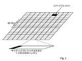
LTEでは、ダウンリンクにおいて直交周波数分割多重(OFDM)を使用し、アップリンクにおいて離散フーリエ変換、DFT、拡散OFDMを使用する。従って、基本のLTE物理通信リソースは、図2の例に示すように、時間−周波数グリッドと見なしてもよく、各リソースエレメントは、(特定のアンテナポートの)1つのOFDMシンボル間隔の1つのサブキャリアに相当する。 In LTE, orthogonal frequency division multiplexing (OFDM) is used in the downlink, and discrete Fourier transform, DFT, and spread OFDM are used in the uplink. Thus, the basic LTE physical communication resource may be viewed as a time-frequency grid, as shown in the example of FIG. 2, where each resource element is one sub-frame of one OFDM symbol interval (for a particular antenna port). Corresponds to a career.
時間領域においては、LTEダウンリンク送信は、10msの無線フレームに編成され、各無線フレームは、図3に示すように、1msの同じサイズのサブフレームを10個有する。サブフレームは、それぞれが継続時間0.5msの、2つのスロットに分割される。 In the time domain, LTE downlink transmissions are organized into 10 ms radio frames, and each radio frame has 10 sub-frames of the same size of 1 ms, as shown in FIG. The subframe is divided into two slots, each of duration 0.5 ms.
LTEにおけるリソース割り当ては、リソースブロックに関して述べられており、リソースブロックは、時間領域において1スロットに、周波数領域において12個の連続する15kHzのサブキャリアに相当する。2つの(時間的に)連続するリソースブロックは、リソースブロックペアに相当し、送信スケジューリングが機能する時間間隔に相当する。 Resource allocation in LTE is described in terms of resource blocks, which correspond to one slot in the time domain and 12 consecutive 15 kHz subcarriers in the frequency domain. Two (in time) consecutive resource blocks correspond to resource block pairs and correspond to time intervals in which transmission scheduling functions.
LTEにおける送信は、サブフレームごとに動的にスケジュールされる。RBSは、サブフレームごとに、ダウンリンク割り当て/アップリンク送信許可を、物理ダウンリンク制御チャネルPDCCHによって、特定のUE(LTEの移動無線機)に送信する。PDCCH信号は、各サブフレームの最初の1つ以上のOFDMシンボルで送信され、(大体)システム帯域幅全体に及ぶ。UEは、PDCCHによって運ばれたダウンリンク割り当てを復号すると、サブフレーム内のどのリソースエレメントが自UE向けのデータを有しているかを知る。同様に、アップリンク送信許可の受信時、UEは、どの時間/周波数のリソースで送信すべきかを知る。LTEのダウンリンクにおいては、データは、物理ダウンリンク共有チャネル(PDSCH)で運ばれ、アップリンクにおいて対応するデータチャネルは、物理アップリンク共有チャネル(PUSCH)と呼ばれる。 Transmission in LTE is dynamically scheduled every subframe. For each subframe, the RBS transmits downlink assignment / uplink transmission permission to a specific UE (LTE mobile radio) through the physical downlink control channel PDCCH. The PDCCH signal is transmitted in the first one or more OFDM symbols of each subframe and spans (roughly) the entire system bandwidth. When the UE decodes the downlink assignment carried by the PDCCH, the UE knows which resource element in the subframe has data for its own UE. Similarly, upon reception of an uplink transmission grant, the UE knows on which time / frequency resource to transmit. In the LTE downlink, data is carried on a physical downlink shared channel (PDSCH), and the corresponding data channel in the uplink is called a physical uplink shared channel (PUSCH).
送信されたデータを復調するには、無線チャネルを推定する必要があり、この推定は、送信された参照シンボル(RS)、すなわち受信機が既に知っているシンボルを使用して行われる。LTEにおいては、全てのダウンリンクサブフレームで、セル固有参照シンボル(CRS)が送信される。CRSは、ダウンリンクチャネルの推定を助けることに加えて、UEが行う移動性測定およびアップリンク電力制御にも使用される。LTEでは、復調のためのチャネル推定を助けることだけを目的としたUE固有のRSもサポートしている。 In order to demodulate the transmitted data, it is necessary to estimate the radio channel, and this estimation is performed using the transmitted reference symbols (RS), i.e. symbols already known to the receiver. In LTE, a cell specific reference symbol (CRS) is transmitted in all downlink subframes. In addition to helping estimate the downlink channel, CRS is also used for mobility measurements and uplink power control performed by the UE. LTE also supports UE specific RSs that are only intended to help channel estimation for demodulation.
図4は、物理制御/データチャネルと信号の、ダウンリンクサブフレーム内のリソースエレメントへのマッピングを示す。この例においては、PDCCHは、3つの可能なOFDMシンボルの中の最初のシンボルだけを占有するので、この特定の例では、データのマッピングを、2番目のOFDMシンボルから始めることができる。CRSはセル内の全てのUEに共通であるので、特定のUEの必要性に適応させるようにCRSの送信を適合させることは容易にできない。このことは、UE固有のRSとは対照的であり、UE固有のRSに関しては、各UEがPDSCHの一部として図4のデータ領域に配置される自UEのRSを有する。 FIG. 4 shows the mapping of physical control / data channels and signals to resource elements in the downlink subframe. In this example, the PDCCH occupies only the first symbol of the three possible OFDM symbols, so in this particular example, the data mapping can begin with the second OFDM symbol. Since CRS is common to all UEs in a cell, it is not easy to adapt the transmission of CRS to adapt to the needs of a particular UE. This is in contrast to UE-specific RSs, where each UE has its own RS that is located in the data region of FIG. 4 as part of the PDSCH.
制御領域の長さは、サブフレームごとに変わってもよく、物理制御フォーマットインジケータチャネル(PCFICH)で伝達される。PCFICHは、UEが知っている、制御領域内の位置で送信される。UEは、PCFICHを復号した後は、制御領域のサイズと、どのOFDMシンボルからデータ送信が始まるかを知っている。 The length of the control region may vary from subframe to subframe and is conveyed in a physical control format indicator channel (PCFICH). The PCFICH is transmitted at a location in the control area known to the UE. After decoding the PCFICH, the UE knows the size of the control region and from which OFDM symbol the data transmission starts.
制御領域で同様に送信されるのは、物理ハイブリッドARQインジケータチャネルである。このチャネルは、ACK/NACK応答をUEに運び、前のサブフレームのアップリンクデータ送信が基地局で正しく復号されたか否かを通知する。 Also transmitted in the control region is a physical hybrid ARQ indicator channel. This channel carries an ACK / NACK response to the UE and informs whether the uplink data transmission of the previous subframe has been correctly decoded at the base station.
例えばUEなどのLTE端末は、LTEネットワークと通信ができるようになる前に、まず、ネットワーク内のセルまたはRBSを見つけて同期しなければならない。すなわち、セルサーチをしなければならない。次いで、セルもしくはRBSと通信するために必要な、およびセルもしくはRBS内で適切に動作するために必要な、システム情報を受信して復号し、最後にランダムアクセス手順でセルにアクセスする必要がある。 For example, an LTE terminal such as a UE must first find and synchronize a cell or RBS in the network before it can communicate with the LTE network. That is, a cell search must be performed. Then, it is necessary to receive and decode system information necessary to communicate with the cell or RBS and to operate properly in the cell or RBS, and finally to access the cell with a random access procedure .
移動性をサポートするために、UEは、そのサービングセル/RBSと隣接セル/RBSの両方を継続的にサーチし、同期をとり、受信品質を推定する必要がある。次いで、(接続モードのUEに関して)ハンドオーバまたは(アイドルモードのUEに関して)セル再選択が行われるべきかどうかを判定するために、現在のセルの受信品質に対する隣接セルの受信品質が評価される。接続モードのUEに関しては、ハンドオーバの決定は、UEが提供する測定報告に基づいてネットワークが行う。その報告の例は、参照信号受信電力(RSRP)および参照信号受信品質(RSRQ)である。これらの測定値が、たぶん設定可能なオフセットによって補完されて、どのように使用されるかに応じて、UEは、例えば、受信電力が最大のセル/RBSに、パス利得が最も良いセル/RBSに、またはこれら2つの間のどれかのセル/RBSに接続されてもよい。 In order to support mobility, the UE needs to continuously search and synchronize both its serving cell / RBS and neighboring cells / RBS and estimate the reception quality. The neighbor cell reception quality is then evaluated relative to the current cell reception quality to determine whether handover (for connected mode UE) or cell reselection (for idle mode UE) should be performed. For a connected mode UE, the handover decision is made by the network based on a measurement report provided by the UE. Examples of the report are reference signal received power (RSRP) and reference signal received quality (RSRQ). Depending on how these measurements are used, possibly supplemented by a configurable offset, the UE may, for example, receive the cell / RBS with the highest received power and the cell / RBS with the best path gain. Or any cell / RBS between the two.
これらの選択方策は、異なるタイプのセルのRBSの出力電力が異なるので、同じセルを選択しない。このことは、時には、リンクアンバランスと呼ばれる。例えば、図5を見ると、ピコRBS510または中継器の出力電力は約30dBm以下であるのに対して、マクロRBS500は、46dBmの出力電力を有することができる。その結果、ピコセルの近傍においてさえ、マクロRBS500からのダウンリンク信号強度は、ピコRBS510の信号強度より大きいことがある。ダウンリンクの視点からは、ダウンリンク受信電力に基づいてセル/RBSを選択する方が良いことが多いのに対して、アップリンクの視点からは、パスロスに基づいてセル/RBSを選択した方が良いであろう。
These selection strategies do not select the same cell because the RBS output power of different types of cells is different. This is sometimes called link imbalance. For example, referring to FIG. 5, the output power of the
上記のシナリオにおいて、マクロダウンリンクの方がピコセルダウンリンクよりはるかに信号強度が大きい場合でさえ、システムの視点からは、ピコセル/RBS510に接続する方が良いことがある。しかし、UEがUL境界511とDL境界512との領域内で動作するとき、レイヤをまたがるICICが必要であろう。このエリアは、リンクアンバランスゾーンとも呼ばれる。ダウンリンク制御シグナリングに関して、セルレイヤをまたがる何らかの形態の干渉制御が特に重要である。この干渉状況が適切に処理されない場合、図5のDL境界とUL境界との間の領域にいて、ピコRBS510に接続しているUEは、ピコRBS510からダウンリンク制御シグナリングを受信できない。
In the above scenario, it may be better to connect to the picocell /
レイヤをまたがるICICを提供する1つのアプローチを図6に示す。図6では、干渉(ピコセル/RBSに対するダウンリンク干渉)するマクロRBSは、ある特定のサブフレームに、ユニキャストトラヒックをスケジュールすることを避ける。これは、それらのサブフレームにおいて、PDCCHもPDSCHも発生しないことを意味している。このようにすると、低干渉サブフレームを作成することができ、この低干渉サブフレームは、リンクアンバランスゾーンで動作しているピコユーザを保護するために使用することができる。ここで、ピコユーザというのは、ピコRBSに接続しているUEである。マクロRBS(MeNB)は、バックホールインタフェースX2を介してピコRBS(PeNB)に、どのサブフレーム内にUEをスケジュールしないかを示す。次いで、PeNBは、リンクアンバランスゾーン内で動作しているUEをスケジュールするとき、これらのUEをマクロレイヤの低干渉サブフレームの位置と合ったサブフレーム、すなわち干渉保護サブフレームにスケジュールするように、この情報を考慮することができる。しかし、DL境界内で動作しているピコセルUEは、全てのサブフレーム、すなわち保護サブフレームと非保護サブフレームの両方にスケジュールされてもよい。 One approach for providing ICIC across layers is shown in FIG. In FIG. 6, a macro RBS that interferes (downlink interference for a pico cell / RBS) avoids scheduling unicast traffic in certain subframes. This means that neither PDCCH nor PDSCH occurs in those subframes. In this way, a low-interference subframe can be created, and this low-interference subframe can be used to protect pico users operating in the link unbalance zone. Here, the pico user is a UE connected to the pico RBS. The macro RBS (MeNB) indicates in which subframe the UE is not scheduled to the pico RBS (PeNB) via the backhaul interface X2. Then, when the PeNB schedules UEs operating in the link imbalance zone, it schedules these UEs in subframes that are aligned with the low interference subframes of the macro layer, ie, interference protection subframes This information can be taken into account. However, a picocell UE operating within the DL boundary may be scheduled in all subframes, ie both protected and unprotected subframes.
原理上は、異なるレイヤにおけるデータ送信は、例えば異なるRBS間で調整メッセージを交換することによって、2つのセルレイヤにおけるスケジューリング決定を周波数領域において確実に重ならないようにすることによって、周波数領域でも分離することができる。制御シグナリングに関しては、制御シグナリングが全帯域幅に及ぶLTEの仕様においては、これは可能でない。従って、時間領域アプローチを使用する必要がある。 In principle, data transmission in different layers can also be separated in the frequency domain by ensuring that scheduling decisions in the two cell layers do not overlap in the frequency domain, for example by exchanging coordination messages between different RBSs. Can do. With regard to control signaling, this is not possible in the LTE specification where control signaling spans the entire bandwidth. Therefore, it is necessary to use a time domain approach.
ネットワークを展開する1つのやり方は、異なる送信/受信ポイントに、個別のセルを形成させることである。言い換えると、あるポイントから送信する信号、またはあるポイントで受信する信号を、他の近隣のポイントで使用されているセルIDとは異なるセルIDに関係させる。典型的に、各ポイントは、ブロードキャストチャネル(例えば、物理ブ報知チャネル(PBCH))および同期チャネル(例えば、プライマリ同期信号(PSS)およびセカンダリ同期信号(SSS))に関して、自身の唯一の信号を送信する。 One way to deploy the network is to have separate cells at different transmission / reception points. In other words, a signal transmitted from a certain point or a signal received at a certain point is related to a cell ID different from a cell ID used at another neighboring point. Typically, each point transmits its only signal with respect to the broadcast channel (eg, physical broadcast channel (PBCH)) and synchronization channel (eg, primary synchronization signal (PSS) and secondary synchronization signal (SSS)). To do.
ポイントのコンセプトは、多地点協調(CoMP)の技術とともに使用されることが多い。これに関連して、ポイントは、本質的に同じ地理的エリアを同様にカバーしているアンテナセットに相当する。従って、ポイントは、1つのサイトにおける複数のセクタの1つに相当してもよいが、同様の地理的エリアを全てがカバーしようとしている1つ以上のアンテナを有する1つのサイトにも相当してもよい。たいてい、異なるポイントは異なるサイトを表す。複数のアンテナは、それらが地理的に十分に分離れているとき、および/または十分に異なる方向を指すアンテナダイアグラムを有しているとき、異なるポイントに相当する。CoMP技術は、スケジューリングの視点からは、ポイントが他のポイントからほぼ独立して動作している従来のセルラシステムとは対照的に、異なるポイント間のスケジューリングまたは送信/受信に依存性を持ち込む。 The point concept is often used in conjunction with multi-point coordination (CoMP) technology. In this context, a point corresponds to an antenna set that covers essentially the same geographical area as well. Thus, a point may correspond to one of multiple sectors at one site, but also corresponds to one site with one or more antennas all trying to cover a similar geographical area. Also good. Usually, different points represent different sites. Multiple antennas correspond to different points when they are geographically well separated and / or have antenna diagrams pointing in sufficiently different directions. CoMP technology introduces a dependency on scheduling or transmission / reception between different points, in contrast to conventional cellular systems where points operate almost independently of other points from a scheduling perspective.
ポイント当たり1つのセルIDのこの典型的な方策について、図7に、高電力マクロポイントまたは高電力RBSのカバーエリア内に複数の低電力(ピコ)ポイントまたは低電力(ピコ)RBSが配置されているヘテロジニアス配置に関して示す。同様の原理は、全てのポイントが同様の出力電力を有し、ヘテロジニアス配置の場合にありうる配置より規則的な方法でおそらく配置される、伝統的なマクロセルラ配備にも適用される。図7では、カバーエリアまたはセル701を有する1つのマクロポイントまたはマクロRBS700が示されている。セル701は、セルID1を有する。マクロセル701内に、3つの異なる低電力ポイント/RBS710、720および730が配備されている。各低電力ポイント/RBSは、それぞれカバーエリアまたはピコセル711、721および731を有する。3つの異なるピコセルは、それぞれ固有のセルIDを有する。すなわち、ピコセル711はセルID2を有し、ピコセル721はセルID3を有し、ピコセル731はセルID4を有する。
For this exemplary strategy of one cell ID per point, FIG. 7 shows multiple low power (pico) points or low power (pico) RBSs placed within the coverage area of a high power macropoint or high power RBS. The heterogeneous configuration is shown. Similar principles apply to traditional macrocellular deployments where all points have similar output power and are probably arranged in a more regular manner than would be possible with a heterogeneous deployment. In FIG. 7, one macro point or
典型的な配備方策に対する代替方策は、代わりに、高電力マクロポイントのカバー範囲によって輪郭が示される地理的エリア内の全てのUEに、同じセルIDに関係する信号を使用して、サービスを提供するものである。言い換えると、UEの視点からは、受信信号は、単一のセルから来るように見える。図7を見ると、セル701、711、721および731の全ては、同じセルID、例えばセルID1を有する。マクロポイント/RBS700は、1つだけ示されており、他のマクロポイントは、それらが同じサイト(マクロサイトの他のセクタに相当)に配置されない限り、異なるセルID(異なるセルに相当)を使用するであろう。数個のマクロポイントが同一場所に配置される場合は、同じセルIDが、同一場所に配置された複数のマクロポイントと、複数のマクロポイントのカバーエリアに統合にされたピコポイントとにまたがって共有されてもよい。同期チャネル、ブロードキャストチャネル(BCH)および制御チャネルは、全て、高電力ポイントから送信されるのに対して、データは、UE固有RSを当てにする共用データ送信チャネルPDSCHを使用して、低電力ポイントからもUEに送信されてもよい。このようなアプローチは、UE固有のRSに基づくPDSCHが可能なUEにとっては有利であるのに対して、PDSCHのCRSだけをサポートするUE(このUEには、周波数分割複信、FDD、に関してLTEリリース8/9対応の全てのUEを少なくとも含みそうである)は、高電力ポイントからの送信を処理しなければならず、それ故、ダウンリンクにおいては、特別な低電力ポイントの配備から利益を得ないであろう。
An alternative to a typical deployment strategy is instead to serve all UEs in the geographic area outlined by the high power macropoint coverage using signals related to the same cell ID To do. In other words, from the UE perspective, the received signal appears to come from a single cell. Looking at FIG. 7, all of the
単一セルIDアプローチは、同じセルに関係しているポイント間に高速バックホール通信がある状況を対象としている。一例は、マクロレベルで1つ以上のセクタにサービスを提供するとともに、同じセルIDを共有する他のポイントの役割を演じる遠隔無線ユニット(RRU)と高速ファイバ接続するRBSであってもよい。これらのRRUは、1つ以上のアンテナをそれぞれが有する低電力ポイントを代表してもよい。別の例は、全てのポイントが、他のポイントより重要であるポイントが1つもない、同様の電力クラスを有するときである。RBSは、全てのRRUからの信号を同様に処理する。 The single cell ID approach is intended for situations where there is high-speed backhaul communication between points associated with the same cell. An example may be an RBS that provides high speed fiber connectivity with a remote radio unit (RRU) that serves one or more sectors at the macro level and plays the role of another point sharing the same cell ID. These RRUs may represent low power points each having one or more antennas. Another example is when all points have a similar power class where no single point is more important than the other points. The RBS processes the signals from all RRUs in the same way.
典型的なアプローチと比べた共有セルアプローチの利点は、セル/RBS間の通常のハンドオーバ手順がマクロで呼び出される必要があるに過ぎないことである。別の利点は、CRSがポイントごとに送信される必要がないので、CRSからの干渉が大幅に低減されることである。ポイント間の協調およびスケジューリングによって大きな融通性もあるので、ネットワークは、図6に示す準静的に構成された「低干渉」サブフレームの融通性のないコンセプトに頼るのを回避することができる。また、共有セルアプローチは、ダウンリンクをアップリンクから切り離すことも可能にするので、例えば、パスロスベースの受信ポイントの選択は、ダウンリンクに対して深刻な干渉の問題を生じることなく、アップリンクで行うことができる。ここで、UEは、アップリンク受信で使用されるポイントとは異なる送信ポイントからサービスを提供されてもよい。通常この意味することは、UEのアップリンク送信は、ピコポイントで受信されるのに対して、UEは、マクロポイントからダウンリンク送信を受信するということである。 The advantage of the shared cell approach compared to the typical approach is that the normal handover procedure between cells / RBS only needs to be invoked in a macro. Another advantage is that the interference from the CRS is greatly reduced since the CRS does not need to be transmitted point by point. Because there is also great flexibility through point-to-point coordination and scheduling, the network can avoid relying on the inflexible concept of the quasi-statically configured “low interference” subframe shown in FIG. The shared cell approach also allows the downlink to be decoupled from the uplink, for example, the selection of a path loss based reception point in the uplink without causing serious interference issues for the downlink. It can be carried out. Here, the UE may be served from a transmission point different from the point used for uplink reception. This usually means that the UE's uplink transmission is received at a pico point, whereas the UE receives a downlink transmission from a macro point.
3GPPのLTEリリース10によれば、アップリンク電力制御(UL PC)は、パスロス(PL)項を推定し、それを種々のUE固有およびセル固有の電力オフセット項と組み合わせることによって行われる。リリース10の一例の電力制御(PC)式は、次の形態である。
P=min(Pmax, 10log10(M+P0+α×PL+C))[dBm] (1)
上式で、Pmaxは、出力電力(dBm単位)の上限を表し、Mは、スケジュールされたULの帯域幅を表し、P0は、UE固有および/またはセル固有の電力オフセットであり、αは、セル固有部分パスロス補償係数であり、PLは、UEが行うパスロスの推定値であり、Cは、閉ループ電力制御補正項を含み得る複数の電力補正項の合成として取得され得る補正項である。
According to LTE Release 10 of 3GPP, uplink power control (UL PC) is performed by estimating a path loss (PL) term and combining it with various UE specific and cell specific power offset terms. An example of a power control (PC) formula for release 10 is in the following form.
P = min (Pmax, 10log10 (M + P0 + α × PL + C)) [dBm] (1)
Where Pmax represents the upper limit of output power (in dBm), M represents the bandwidth of the scheduled UL, P0 is the UE specific and / or cell specific power offset, and α is It is a cell-specific partial path loss compensation coefficient, PL is an estimated value of path loss performed by the UE, and C is a correction term that can be obtained as a combination of a plurality of power correction terms that can include a closed loop power control correction term.
UEは、セル固有共通参照信号(CRS)の受信電力とその参照信号の公称電力との差(dB単位)に基づいて、パスロスPLを推定する。
PL=参照信号電力−高位レイヤでフィルタリングされたRSRP (2)
上式で、参照信号電力は、高位レイヤシグナリングによって設定され、RSRPは、参照サービングセルに関して定められる。RSRPのフィルタリングは、高位レイヤシグナリングによって設定され、UEによって行われてもよい。参照サービングセルとして選択され、参照信号電力および高位レイヤフィルタ済みRSRPを特定するために使用されるサービングセルは、高位レイヤパラメータであるパスロス参照リンキングによって設定される。
The UE estimates the path loss PL based on the difference (in dB) between the received power of the cell-specific common reference signal (CRS) and the nominal power of the reference signal.
PL = reference signal power−RSRP filtered at higher layer (2)
Where the reference signal power is set by higher layer signaling and RSRP is defined for the reference serving cell. RSRP filtering may be configured by higher layer signaling and performed by the UE. The serving cell that is selected as the reference serving cell and used to identify the reference signal power and higher layer filtered RSRP is set by the path loss reference linking, which is a higher layer parameter.
アップリンク電力制御の問題は、RBSから送信されたCRSおよび参照電力レベルに基づいて、UEがその送信電力を調整するので、アップリンク動作とダウリンク動作の切り離しが、UEの開ループの出力電力設定の部分に適用されないことである。場合によっては、開ループの電力制御部分は、例えばUEが開ループ電力制御だけを使用しているとき、出力電力を完全に決定することがある。ダウンリンクにおいて、UEがマクロRBS/セルからサービスを提供されている場合、送信電力を決定するRSRP測定において、ピコノード/RBSを考慮に入れない。この意味することは、ピコノード/RBSにおける受信電力を、UE固有および/またはセル固有の電力オフセットP0によって決定される受信電力よりはるかに大きくさせる電力レベルで、UEが送信するということである。この場合、ネットワークは、UEの出力電力をネットワークが適当と見なす値に導くために閉ループ電力制御を採用してもよい。これは、アップリンク許可の中で送信電力コマンド、TPC、をUEに送信することによって行われてもよい。TPCは、2ビットの命令であり、絶対的な設定かまたは累積値であってもよい。累積値は、大きいダイナミックレンジにわたって電力を制御する場合に必要とされ、4つの値[−1、0、1、2]dBの中の1つを取る。 The problem of uplink power control is that the UE adjusts its transmit power based on the CRS and reference power level transmitted from the RBS, so the decoupling of uplink and downlink operations will result in the UE's open loop output power. It does not apply to the setting part. In some cases, the open loop power control portion may fully determine the output power, for example when the UE is using only open loop power control. In the downlink, when the UE is served from a macro RBS / cell, the pico node / RBS is not taken into account in the RSRP measurement to determine the transmission power. This means that the UE transmits at a power level that causes the received power at the pico node / RBS to be much greater than the received power determined by the UE-specific and / or cell-specific power offset P0. In this case, the network may employ closed loop power control to guide the output power of the UE to a value deemed appropriate by the network. This may be done by sending a transmit power command, TPC, to the UE in the uplink grant. The TPC is a 2-bit instruction and may be an absolute setting or a cumulative value. The cumulative value is needed when controlling power over a large dynamic range and takes one of four values [-1, 0, 1, 2] dB.
様々なノード/RBSの出力電力が不ぞろいであり、共有セルID設定においては、CRSは、マクロノード/RBSとピコノード/RBSとで共有されることから、UEの電力制御は、エリア分割利得を達成するのに有害である。マクロノード/RBSは、ピコノード/RBSよりはるかに大きい出力電力を有するので、アップリンクにおいてピコRBSがサービスを提供できるUEは、マクロRBS/セルがピコRBS/セルよりはるかに小さいパス利得しかないにもかかわらず、マクロRBSに向けてその送信電力を調整することがあまりにも多い。この出力は、セル内に過剰な干渉を作り出しそうであり、それによってセル内のマルチユーザアクセス(例えば、SDMA)の可能性を小さくする。また、大き過ぎる出力電力が使用される場合、UEの電力消費は、不必要に大きくなる。 Since the output power of various nodes / RBS is uneven, and CRS is shared by macro node / RBS and pico node / RBS in shared cell ID setting, UE power control achieves area division gain Harmful to do. Since the macro node / RBS has much higher output power than the pico node / RBS, UEs that can be served by the pico RBS in the uplink have only a path gain where the macro RBS / cell is much smaller than the pico RBS / cell. Nevertheless, it is too often to adjust its transmit power towards the macro RBS. This output is likely to create excessive interference within the cell, thereby reducing the possibility of multi-user access (eg, SDMA) within the cell. Also, if too much output power is used, the UE power consumption is unnecessarily high.
本発明の目的は、先に概要を述べた課題の少なくとも一部を解決することである。特に、1つの目的は、アップリンク送信の送信電力制御を行うUEと、そのUEにおけるアップリンク送信の送信電力制御方法とを提供することである。ここで、UEは、RSの測定値および参照送信電力レベルに基づいて、示された少なくとも1つのRSに対するパスロスを決定する。これらの目的および他の目的は、添付の独立請求項に記載されているUEおよびUEにおける方法を提供することにより達成することができる。 The object of the present invention is to solve at least some of the problems outlined above. In particular, one object is to provide a UE that performs transmission power control for uplink transmission and a transmission power control method for uplink transmission in the UE. Here, the UE determines a path loss for the indicated at least one RS based on the measured value of the RS and the reference transmission power level. These and other objects can be achieved by providing a UE and a method in the UE as set forth in the appended independent claims.
一態様によれば、UEにおけるアップリンク送信の送信電力制御の方法が提供される。この方法は、シグナリングによって、少なくとも1つの参照信号(RS)を示す構成と、示された各RSに対する参照送信電力レベルを受信する工程を有する。方法は、示された少なくとも1つのRSの受信電力を測定する工程と、測定された各受信電力に関して、測定された受信電力と測定された受信電力測定値に対する参照送信電力レベルに基づいて、パスロス(PL)を決定する工程とを更に有する。方法は、少なくとも1つの決定されたPLに基づいて、アップリンク送信電力を決定する工程を更に有する。 According to one aspect, a method for transmit power control of uplink transmission at a UE is provided. The method includes a configuration indicating at least one reference signal (RS) by signaling and receiving a reference transmission power level for each indicated RS. The method measures the received power of the indicated at least one RS and, for each measured received power, a path loss based on the measured received power and a reference transmit power level relative to the measured received power measurement. (PL) is further included. The method further comprises determining an uplink transmission power based on the at least one determined PL.
一態様によれば、アップリンク送信の送信電力制御のために構成されたUEが提供される。UEは、少なくとも1つの参照信号(RS)を示す構成と、示された各RSに対する参照送信電力レベルとを受信するように構成された受信モジュールを有している。UEは、示された少なくとも1つのRSの受信電力を測定するように構成された測定モジュールと、測定された受信電力とその測定された受信電力に対する参照送信電力レベルとに基づいて、パスロス(PL)を決定するように構成された決定モジュールとを更に備えている。この決定モジュールは、少なくとも1つの決定されたPLに基づいて、アップリンク送信電力を決定するように更に構成されている。 According to one aspect, a UE configured for transmit power control of uplink transmission is provided. The UE has a receiving module configured to receive a configuration indicating at least one reference signal (RS) and a reference transmission power level for each indicated RS. The UE determines a path loss (PL) based on the measurement module configured to measure the received power of the indicated at least one RS, and the measured received power and a reference transmit power level for the measured received power. And a determination module configured to determine. The determination module is further configured to determine uplink transmission power based on the at least one determined PL.
アップリンク送信の送信電力制御を行うUEと、そのUEにおけるアップリンク送信の送信電力制御方法とは、幾つかの利点を有する。例えば、UEは、アップリンク電力制御をダウンリンクCRSから切り離し、UEがどのように送信電力を設定すべきかを制御する融通性の大きいやり方を、ネットワークに提供する。別の利点は、最小の(または少なくともより小さい)パスロスを有するノードに向けて送信電力を制御することによって、大きなエリア分割利得を得られるということである。更に、電力制御は、自由に設定可能なUE固有等価チャネルに基づいていてもよい。送信電力を減少することができ、自セルおよび他セルへの干渉を最小にすることができ、空間分割多重接続の可能性の増加およびUEバッテリ寿命の改善を可能にする。 A UE that performs transmission power control for uplink transmission and a transmission power control method for uplink transmission in the UE have several advantages. For example, the UE decouples uplink power control from the downlink CRS and provides the network with a flexible way to control how the UE should set transmit power. Another advantage is that a large area division gain can be obtained by controlling the transmit power towards the node with the smallest (or at least smaller) path loss. Furthermore, the power control may be based on a UE-specific equivalent channel that can be freely set. The transmission power can be reduced, the interference to the own cell and other cells can be minimized, and the possibility of space division multiple access is increased and the UE battery life is improved.
以下、実施形態について、添付の図に関して、より詳細に説明する。 Hereinafter, embodiments will be described in more detail with reference to the accompanying drawings.
簡潔に述べると、アップリンク送信の送信電力制御を行うUEと方法が提供される。ここで、UEは、UEが測定する少なくとも1つの参照信号(RS)を示す構成メッセージを受信し、示されたRSの測定を実行し、測定の実行に基づいてアップリンク送信電力を決定する。 Briefly, a UE and method for performing transmit power control for uplink transmission are provided. Here, the UE receives a configuration message indicating at least one reference signal (RS) that the UE measures, performs a measurement of the indicated RS, and determines an uplink transmission power based on the performance of the measurement.
ここで、図8aを参照する。図8aは、UEにおけるアップリンク送信の送信電力制御方法の例示的実施形態を、フローチャートを用いて示している。 Reference is now made to FIG. FIG. 8a shows an exemplary embodiment of a transmission power control method for uplink transmission at the UE using a flowchart.
図8aは、UEにおけるアップリンク送信の送信電力制御の方法800は、シグナリングを通じて、少なくとも1つの参照信号(RS)を示す構成と、示された各RSの参照送信電力レベルとを受信する工程810を有することを示している。この方法は、示された少なくとも1つのRSの受信電力を測定する工程820と、測定した受信電力のそれぞれに関して、受信電力測定値およびその受信電力測定値に対する参照送信電力レベルに基づいて、パスロスPLを決定する工程830を更に有する。方法は、少なくとも1つの決定されたPLに基づいて、アップリンク送信電力を決定する工程840を更に有する。
FIG. 8a shows that a
より詳細には、この方法によれば、UEは、シグナリングを通じて、UEが測定する少なくとも1つの参照信号(RS)を示す構成を受信する。また、UEは、示された各RSに対する参照送信電力レベルも受信する。この構成は、一例では、マクロノードまたはRBSから送信される。マクロノード/RBSに接続されていることを意味するUEに、マクロノード/マイクロノード/RBSが、現在サービスを提供しているか、あるいは、UEは、マクロノード/RBSすなわちマクロセルのカバーエリア内に配備される、おそらく複数の低電力ノード/RBS例えばピコノード/RBSなどの1つによってサービスを提供されているかである。関与するノードが、RRUとして配備されるピコRBSの場合のように、同じRBSまたはeNBによって制御されるとき、全ての情報は、単一のノードで入手可能である。ノードがスタンドアロンRBSである場合、情報は、ノード間のX2インタフェースによって交換されてもよく、それによって、必要な情報が取得される。 More specifically, according to this method, the UE receives a configuration indicating at least one reference signal (RS) that the UE measures through signaling. The UE also receives a reference transmission power level for each indicated RS. This configuration is, in one example, transmitted from a macro node or RBS. For a UE that is connected to a macro node / RBS, the macro node / micro node / RBS is currently serving or the UE is deployed within the coverage area of the macro node / RBS or macro cell Is possibly served by one of a plurality of low power nodes / RBS, eg, pico nodes / RBS. When the participating nodes are controlled by the same RBS or eNB, as in the case of a pico RBS deployed as an RRU, all information is available at a single node. If the node is a stand-alone RBS, the information may be exchanged via an X2 interface between the nodes, thereby obtaining the necessary information.
UEは、構成をいったん受信すると、どのRSを測定すべきかが分かる。UEは、たぶん複数のRSのそれぞれに関して、示された各RSのそれぞれの参照送信電力レベルも通知される。各RSは、一般に、特定の送信電力レベルを使用して、(マクロまたは低電力)ノード/RBSから送信される。送信電力レベルは、RSごとに個別であってもよい。UEは、構成によって、1つ以上のどの異なるRSを測定すべきか、およびそれぞれ1つ1つのRSが送信されるそれぞれの送信電力レベルについて通知される。 The UE knows which RS to measure once it receives the configuration. The UE is also notified of each reference transmission power level of each indicated RS, perhaps for each of the plurality of RSs. Each RS is typically transmitted from a node / RBS (macro or low power) using a specific transmit power level. The transmission power level may be individual for each RS. Depending on the configuration, the UE is informed about which one or more different RSs are to be measured and for each transmission power level at which each one RS is transmitted.
次いで、UEは、示されたRSのそれぞれの受信電力レベルを測定する。測定した受信電力レベルと、参照電力レベル、すなわちRSが送信された電力レベルとに基づいて、UEは、示されたRSのそれぞれに対するPLを決定する。PLは、一例では、計算によって決定される。言い換えると、示された各RSに関して、UEは、そのRSの受信電力レベルを測定し、測定した受信電力レベルに基づいて、および示された参照電力レベルに基づいて、そのRSに対するPLを決定する。 The UE then measures the received power level for each of the indicated RSs. Based on the measured received power level and the reference power level, i.e., the power level at which the RS was transmitted, the UE determines a PL for each of the indicated RSs. PL is determined by calculation in one example. In other words, for each indicated RS, the UE measures the received power level of that RS and determines the PL for that RS based on the measured received power level and based on the indicated reference power level. .
その後、UEは、示されたRSのそれぞれに対する少なくとも1つの決定されたPLに基づいて、アップリンク送信電力を決定する。 The UE then determines uplink transmission power based on at least one determined PL for each of the indicated RSs.
この方法は、幾つかの利点を有する。例えば、UEにおける方法は、アップリンク電力制御をダウンリンクCRSから切り離し、UEがどのように送信電力を設定すべきかを制御する融通性の高いやり方を、ネットワークに提供する。別の利点は、最小(または少なくともより小さい)パスロスを有するノードに向けて送信電力を制御することによって、大きなエリア分割利得を得られるということである。更に、電力制御は、自由に構成できるUE固有等価チャネルに基づいてもよい。送信電力を減少することができ、自セルおよび他セルへの干渉を最小にすることができ、空間分割多重接続の可能性の増加およびバッテリ寿命の改善を可能にする。 This method has several advantages. For example, the method at the UE decouples uplink power control from the downlink CRS and provides the network with a flexible way to control how the UE should set the transmit power. Another advantage is that a large area division gain can be obtained by controlling the transmit power towards the node with the smallest (or at least smaller) path loss. Furthermore, power control may be based on a UE-specific equivalent channel that can be freely configured. The transmission power can be reduced, the interference to the own cell and other cells can be minimized, and the possibility of space division multiple access is increased and the battery life is improved.
一実施形態によれば、アップリンク送信電力を決定する工程は、全ての決定されたPLに基づいて合成されたPLを決定する工程と、合成されたPLに基づいて送信電力を決定する工程とを有する。 According to one embodiment, determining uplink transmission power comprises determining a combined PL based on all determined PLs, and determining a transmission power based on the combined PL. Have
UEは、示された各RSに対するPLをいったん決定すると、アップリンク送信電力を決定するために、決定されたPLを合成する。決定されたPLはそれぞれ1つ1つのRSに対して個別であり、たぶん互いに異なりそうである。複数のRSの受信電力レベルが測定され、その結果として複数のPLが決定されたと仮定すると、PLは、通常、全ての中で最小である1つのPL値から全ての中で最大である1つのPL値までに及び、残りのPL値は、最大値と最小値との間にある。 Once the UE has determined the PL for each indicated RS, the UE combines the determined PL to determine the uplink transmit power. Each determined PL is individual for each RS and is likely to be different from each other. Assuming that the received power levels of multiple RSs are measured and, as a result, multiple PLs have been determined, the PL is usually the one that is the smallest among all the one PL that is the largest among all. Up to the PL value, the remaining PL value is between the maximum and minimum values.
一実施形態によれば、合成されたPLは、決定されたPLの中の最小のPLが選択される。 According to one embodiment, the synthesized PL is selected as the smallest PL among the determined PLs.
上述のように、決定されたPLは、通常、最小の値を有するPL値から最大の値を有するPL値までに及び、その間に複数のPL値がある。PLが大きければ大きいほど、信号がUEで受信されるまでに、送信された信号は損失するか、または送信された信号は減衰する。PLが小さければ小さいほど、信号がUEで受信されるまでに、送信された信号の損失が少なくなるか、または送信された信号の減衰が小さくなる。PLが小さい場合、PLが大きい場合ほど送信された信号は減衰しないので、チャネル条件は良好である。この意味することは、送信された信号を、受信機すなわち(マクロまたはピコ)ノードまたはRBSで確実に正しく受信するために必要な送信電力が、小さいということである。 As described above, the determined PL typically ranges from the PL value having the smallest value to the PL value having the largest value, with a plurality of PL values in between. The higher the PL, the more the transmitted signal is lost or the transmitted signal is attenuated before the signal is received at the UE. The smaller the PL, the less loss of the transmitted signal or less attenuation of the transmitted signal before the signal is received at the UE. When the PL is small, the transmitted signal is not attenuated as the PL is large, so the channel condition is good. This means that the transmission power required to ensure that the transmitted signal is correctly received at the receiver, ie (macro or pico) node or RBS, is small.
一例では、1つ以上のRSは、チャネル状態情報(CSI)フィードバックにも使用されるRSパターンに対応するRSを備えている。 In one example, one or more RSs comprise RSs corresponding to RS patterns that are also used for channel state information (CSI) feedback.
CRSは、LTEで利用可能な唯一の参照シンボルではない。第3世代パートナーシッププロジェクト、3GPP、のLTEリリース10は、PDSCH復調用の個別のUE固有RSと、UEからのチャネル状態情報(CSI)フィードバックのためのチャネル測定用RSとを有する新しいRSコンセプトを導入した。後の方のチャネル測定用RSは、CSI−RSと呼ばれる。CSI−RSは、サブフレームごとには送信されず、一般に、復調用に使用されるRSより時間および周波数においてまばらである。CSI−RSの送信は、RRC設定周期パラメータおよびRRC設定サブフレームオフセットに従って、5番目、10番目、20番目、40番目、または80番目のサブフレームごとに発生してもよい。 CRS is not the only reference symbol available in LTE. 3rd Generation Partnership Project, 3GPP, LTE Release 10 introduces a new RS concept with separate UE specific RS for PDSCH demodulation and channel measurement RS for channel state information (CSI) feedback from the UE did. The latter channel measurement RS is called CSI-RS. CSI-RS is not transmitted every subframe and is generally sparser in time and frequency than RS used for demodulation. The CSI-RS transmission may occur every fifth, tenth, twentieth, forty, or eightyth subframe according to the RRC configuration period parameter and the RRC configuration subframe offset.
「接続モード」で動作しているUEは、例えば適切なランクインジケータ(RI)、1つ以上のプリコーディング行列インデックス(PMI)、およびチャネル品質インジケータ(CQI)の報告などの、CSI報告を行うように、RBSから要求されてもよい。明示的なチャネルフィードバックおよび干渉共分散フィードバックなどの、他の種類のCSIが使用されてもよい。CSIフィードバックは、送信用のサブフレームおよびリソースブロック(RB)の決定と、どの送信方式/プリコーダを使用するかとを含むスケジューリングでRBSを助けるとともに、送信(リンクアダプテーション)のためのユーザビットレートに関する情報を提供する。LTEにおいては、周期的と非周期的の両方のCSI報告をサポートしている。周期的CSI報告の場合には、端末すなわちUEは、設定された周期的時間ごとに、物理アップリンク制御チャネルPUCCHでCSI測定値を報告するのに対して、非周期的報告を使用すると、基地局からCSI許可を受信後の予め指定された時間に、物理アップリンク共用チャネルPUSCHでCSIフィードバックを送信する。従って、非周期的CSI報告を使用すると、RBSは、特定のサブフレームのダウンリンク無線状態を反映するCSIを要求することができる。 A UE operating in “connected mode” may perform CSI reporting, such as reporting an appropriate rank indicator (RI), one or more precoding matrix indices (PMI), and a channel quality indicator (CQI). In addition, it may be requested from the RBS. Other types of CSI may be used, such as explicit channel feedback and interference covariance feedback. CSI feedback aids RBS in scheduling including determination of subframes and resource blocks (RB) for transmission and which transmission scheme / precoder to use, and information on user bit rate for transmission (link adaptation) I will provide a. LTE supports both periodic and aperiodic CSI reporting. In the case of periodic CSI reporting, the terminal or UE reports CSI measurements on the physical uplink control channel PUCCH every configured periodic time, while using aperiodic reporting, the base station CSI feedback is transmitted on the physical uplink shared channel PUSCH at a predesignated time after receiving the CSI grant from the station. Thus, using aperiodic CSI reporting, the RBS can request a CSI that reflects the downlink radio conditions of a particular subframe.
リソースブロックペア内のどのリソースエレメントが、UE固有RSおよびCSI−RSによって潜在的に占有されうるかについての詳細な図、図9a〜cによって提供される。CSI−RSは、2つのアンテナポートを2つの連続するリソースエレメント(RE)にオーバレイするために、長さ2の直交カバーコードを使用する。図示のように、多くの異なるCSI−RSパターンを利用可能である。2つのCSI−RSアンテナポートの場合に関しては、サブフレーム内に20の異なるパターンがある。4つおよび8つのCSI−RSアンテナポートに対応するパターン数は、それぞれ10および5である。TDDに関しては、幾つかの追加のCSI−RSパターンを利用可能である。
A detailed diagram of which resource elements in a resource block pair can potentially be occupied by UE-specific RSs and CSI-RSs is provided by FIGS. 9a-c. CSI-RS uses a
図9a、9b、9cは、異なるCSI−RSポート数を有する2つのリソースブロックRBを備える最小のスケジューリング単位の概略図である。 9a, 9b and 9c are schematic diagrams of a minimum scheduling unit comprising two resource blocks RB having different numbers of CSI-RS ports.
1つの単一リソースブロックは、0.5ms長の1つのスロットと12のサブキャリアを有する。その結果として、最小スケジューリング単位は、1ms長(2スロット)であり、12のサブキャリアを有する。スケジューリング単位は、14×12=168のリソースエレメント、RE、を備えており、1つのREは、1つの参照シンボルを運ぶことができる。通常、1つのスケジューリング単位は、複数の参照シンボルを有している。 One single resource block has one slot of 0.5 ms length and 12 subcarriers. As a result, the minimum scheduling unit is 1 ms long (2 slots) and has 12 subcarriers. The scheduling unit comprises 14 × 12 = 168 resource elements, RE, and one RE can carry one reference symbol. Usually, one scheduling unit has a plurality of reference symbols.
参照信号は、復調のために、および様々なパラメータを測定するために、UEによって使用されてもよい。測定は、例えば、5サブフレーム周期でUEが行う。アンテナポート当たり1つのREがある。RBは、例えば、物理ダウンリンク共有チャネル(PDSCH)に挿入される。2つ、4つまたは8つのCSI−RSポートがあってもよい。再利用係数は、サブフレームオフセット、イントラサブフレーム直交周波数分割多重、OFDM、シンボルシフトおよび周波数シフトによって、高く維持されてもよい。 The reference signal may be used by the UE for demodulation and to measure various parameters. The measurement is performed by the UE in, for example, a 5-subframe period. There is one RE per antenna port. The RB is inserted into, for example, a physical downlink shared channel (PDSCH). There may be 2, 4 or 8 CSI-RS ports. The reuse factor may be kept high by subframe offset, intra-subframe orthogonal frequency division multiplexing, OFDM, symbol shift and frequency shift.
図9aは、2つのCSI−RSポートを有する2つのリソースブロックRBを有する最小スケジューリング単位の概略図である。 FIG. 9a is a schematic diagram of a minimum scheduling unit having two resource blocks RB having two CSI-RS ports.
図9bは、4つのCSI−RSポートを有する2つのリソースブロックRBを有する最小スケジューリング単位の概略図である。 FIG. 9b is a schematic diagram of a minimum scheduling unit having two resource blocks RB having four CSI-RS ports.
図9cは、8つのCSI−RSポートを有する2つのリソースブロックRBを有する最小スケジューリング単位の概略図である。 FIG. 9c is a schematic diagram of a minimum scheduling unit having two resource blocks RB having eight CSI-RS ports.
CSI−RSリソースという用語は、特定のサブフレームの中に存在する特定のパターンに相当する。従って、同じサブフレーム内の2つの異なるパターンの場合、または同じCSI−RSパターンだがサブフレームが異なる場合の両方とも、2つの個別のCSI−RSリソースを構成する。 The term CSI-RS resource corresponds to a specific pattern present in a specific subframe. Therefore, both two different patterns within the same subframe, or the same CSI-RS pattern but different subframes, constitute two separate CSI-RS resources.
また、CSI−RSパターンは、ミュートされた(muted)リソースエレメント(RE)とも呼ばれる、いわゆるゼロ電力CSI−RSにも相当してもよい。ゼロ電力CSI−RSは、REがサイレントである、すなわちそのREで送信される信号がないCSI−RSパターンに相当する。そのようなサイレントパターンは、4アンテナポートCSI−RSパターンに相当する解像度を有して構成される。従って、サイレントにする最小単位は、4つのREに相当する。 The CSI-RS pattern may also correspond to a so-called zero power CSI-RS, also called a muted resource element (RE). Zero power CSI-RS corresponds to a CSI-RS pattern in which an RE is silent, i.e., there is no signal transmitted on that RE. Such a silent pattern is configured with a resolution corresponding to a 4-antenna port CSI-RS pattern. Therefore, the smallest unit to be silent corresponds to four REs.
ゼロ電力CSI−RSの目的は、サイレントにしなければ干渉を引き起こすREをサイレントにするために、干渉を引き起こすセルにゼロ電力CSI−RSを構成することによって、セルにおけるCSI−RSのSINRを高めることである。従って、あるセルのCSI−RSパターンは、干渉を引き起こすセルの対応するゼロ電力CSI−RSパターンに一致する。CSI−RS測定のためにSINRレベルを高めることは、多地点協調(CoMP)などの適用において、またはヘテロジニアス配置において特に重要である。CoMPにおいては、UEは、非サービングセルからのチャネルを測定する必要があり得、その場合、はるかに強いサービングセルからの干渉は、破壊的であるだろう。また、ゼロ電力CSI−RSは、ヘテロジニアス配置でも必要とされ、その場合、マクロレイヤのゼロ電力CSI−RSは、ピコレイヤのCSI−RS送信と一致するように構成される。こうすることにより、UEがピコノードからのチャネルを測定するとき、マクロノードからの強い干渉が回避される。 The purpose of zero power CSI-RS is to increase the SINR of the CSI-RS in the cell by configuring the zero power CSI-RS in the cell causing the interference to silence the RE causing the interference if not making it silent. It is. Thus, a cell's CSI-RS pattern matches the corresponding zero power CSI-RS pattern of the cell causing the interference. Increasing the SINR level for CSI-RS measurement is particularly important in applications such as multipoint coordination (CoMP) or in heterogeneous deployments. In CoMP, the UE may need to measure channels from non-serving cells, in which case interference from a much stronger serving cell will be disruptive. Zero power CSI-RS is also required in a heterogeneous deployment, in which case the macro layer zero power CSI-RS is configured to match the pico layer CSI-RS transmission. By doing this, strong interference from the macro node is avoided when the UE measures the channel from the pico node.
PDSCHは、CSI−RSおよびゼロ電力CSI−RSが占有するREの周りにマッピングされるので、ネットワークとUEの両方が、同じCSI−RS/ゼロ電力CSI−RS構成を仮定することが重要である。そうでなければ、UEは、CSI−RSまたはそのゼロ電力のものを含むサブフレームにおいて、PDSCHを復号することができない。 Since PDSCH is mapped around the RE occupied by CSI-RS and zero power CSI-RS, it is important that both the network and the UE assume the same CSI-RS / zero power CSI-RS configuration. . Otherwise, the UE cannot decode the PDSCH in subframes that include CSI-RS or its zero power one.
アップリンクにおいては、UEから受信ノードへのアップリンクチャネルのCSIを取得するために、いわゆるサウンディング参照シンボル(SRS)が使用されてもよい。SRSが使用される場合、SRSは、サブフレームの最後のDFT拡散OFDMシンボルで送信される。SRSは、アップリンク許可の一部として動的トリガのために、周期送信用にも構成されてもよい。SRSの主要な用途は、アップリンクのスケジューリングおよびリンクアダプテーションを助けることである。しかし、TDDに関しては、ダウンリンクおよびアップリンクに対して同じキャリア周波数が使用されるとき(チャネル相互関係)、ダウンリンクチャネルとアップリンクチャネルが同じであることを利用して、SRSは、時には、ダウンリンクに関するビーム形成重みを決定するために使用される。 In the uplink, so-called sounding reference symbols (SRS) may be used to obtain the CSI of the uplink channel from the UE to the receiving node. If SRS is used, the SRS is transmitted in the last DFT spread OFDM symbol of the subframe. The SRS may also be configured for periodic transmission for dynamic triggering as part of the uplink grant. The primary use of SRS is to aid uplink scheduling and link adaptation. However, for TDD, when the same carrier frequency is used for the downlink and uplink (channel correlation), taking advantage of the fact that the downlink and uplink channels are the same, SRS sometimes Used to determine the beamforming weight for the downlink.
PUSCHがアップリンクのデータを運ぶのに対して、PUCCHは、アップリンクの制御に使用される。PUCCHは、RBペアを使用する狭帯域チャネルであって、2つのRBは、潜在的なスケジューリング帯域幅の反対側にある。PUCCHは、ACK/NACK、周期的CSIフィードバック、およびスケジューリング要求を、ネットワークに伝達するために使用される。 While PUSCH carries uplink data, PUCCH is used for uplink control. PUCCH is a narrowband channel that uses RB pairs, and the two RBs are on opposite sides of the potential scheduling bandwidth. PUCCH is used to communicate ACK / NACK, periodic CSI feedback, and scheduling requests to the network.
CSI−RSは、様々なノードまたはRBSの組み合わせからの、チャネル状態情報のフィードバックに使用される。CSI−RSは、柔軟性およびリソースの直交性を考慮して設計される。例えば、共有セルIDを有するセルに属する全てのノードまたはRBSは、異なるCSI−RSリソースを使用するように構成されてもよい。この場合、リソースは、セル内で直交する。このことは、それらのリソースで行われる測定が、非常に信頼できる可能性を有していることを意味する。UEは、異なるノードまたはRBSまでのPLを推定するために、これらのCSI−RSリソースの全てまたはセットで測定するように構成されている。そのセットは、1つのノードまたはRBSからの送信に相当するただ1つのCSI−RSリソースから構成されてもよい。また、そのセットは、基準としてCRSも有してもよい。いずれにしても、ネットワークは、含まれるCSI−RSリソースおよび/またはCRSの送信に対応する参照出力電力をUEに伝達して、UEが全てのノードまでのPLを計算することができるようにする。次いで、UEは、ノードまたはRBSに向けて、その電力を最小のPLに合わせて調整するために、その電力制御手順の中でこのPL推定を使用してもよい。このようにして、送信電力を減少することができ、自セルおよび他セルへの干渉を減少または最小にすることができ、空間分割多重接続の可能性の増加およびUEバッテリ寿命の改善を可能にする。 CSI-RS is used for feedback of channel state information from various nodes or combinations of RBSs. CSI-RS is designed considering flexibility and resource orthogonality. For example, all nodes or RBSs belonging to a cell having a shared cell ID may be configured to use different CSI-RS resources. In this case, the resources are orthogonal within the cell. This means that measurements made on those resources have the potential to be very reliable. The UE is configured to measure on all or a set of these CSI-RS resources to estimate the PL to different nodes or RBS. The set may consist of only one CSI-RS resource corresponding to transmission from one node or RBS. The set may also have a CRS as a reference. In any case, the network communicates the included CSI-RS resources and / or reference output power corresponding to the transmission of the CRS to the UE so that the UE can calculate the PL to all nodes. . The UE may then use this PL estimation in its power control procedure to adjust its power to the minimum PL towards the node or RBS. In this way, transmit power can be reduced, interference to its own cell and other cells can be reduced or minimized, enabling increased space division multiple access and improved UE battery life. To do.
一例では、構成メッセージは、UEによって測定された少なくとも2つのRSと、その少なくとも2つのRSのそれぞれに対するそれぞれの参照送信電力レベルとを示す。ここで、それぞれのRSは、それぞれ個別のノードに関係しており、受信したRSのそれぞれに対して1つの、少なくとも2つのPLが決定され、その少なくとも2つのRSに関連するそれぞれのアップリンク送信電力が、決定されたPLに基づいて決定される。 In one example, the configuration message indicates at least two RSs measured by the UE and respective reference transmit power levels for each of the at least two RSs. Here, each RS is associated with an individual node, and for each received RS, at least two PLs are determined and each uplink transmission associated with the at least two RSs. The power is determined based on the determined PL.
一例においては、構成メッセージは、UEによって測定される2つのRSと、その少なくとも2つのRSのそれぞれに対するそれぞれの参照送信電力レベルとを示す。それらの2つのRSは、RS−AおよびRS−Bと表わされる。RS−Aは、RTPL−Aで表わされる参照送信電力レベルを有すると示され、RS−Bは、RTPL−Bで表わされる参照送信電力レベルを有すると示される。次いで、UEは、RPL−AおよびRPL−Bで表わされる、RS−AおよびRS−Bのそれぞれの受信電力レベルを測定する。UEは、これらの測定をいったん実行すると、それぞれのパスロスPL−AおよびPL−Bを決定する。PL−Aは、RTPL−AおよびRPL−Aに基づいて決定される。PL−Bは、RTPL−BおよびRPL−Bに基づいて決定される。次いで、UEは、最小のPLを選択し、最小のPLに関連するRSを送信したRBSまたはノードに向けて、アップリンク送信電力を決定する。 In one example, the configuration message indicates two RSs measured by the UE and respective reference transmit power levels for each of the at least two RSs. Those two RSs are denoted RS-A and RS-B. RS-A is shown to have a reference transmission power level represented by RTPL-A, and RS-B is shown to have a reference transmission power level represented by RTPL-B. The UE then measures the respective received power levels of RS-A and RS-B, represented by RPL-A and RPL-B. Once the UE performs these measurements, it determines the respective path loss PL-A and PL-B. PL-A is determined based on RTPL-A and RPL-A. PL-B is determined based on RTPL-B and RPL-B. The UE then selects the minimum PL and determines the uplink transmission power towards the RBS or node that transmitted the RS associated with the minimum PL.
一実施形態によれば、アップリンク送信電力を決定する工程は、示されたRSのそれぞれに関して、少なくとも1つの決定されたPLに基づいて、アップリンク電力を決定する工程を備えている。各決定された電力は、それぞれのノード向けである。 According to one embodiment, determining uplink transmit power comprises determining uplink power based on at least one determined PL for each of the indicated RSs. Each determined power is for a respective node.
更に一実施形態によれば、1つのノードに向けてアップリンク送信電力を決定する工程は、決定されたPLを合成する工程と、次いで合成されたPLに基づいてアップリンク送信電力を決定する工程とを有する。 Further, according to an embodiment, the step of determining the uplink transmission power for one node includes combining the determined PL, and then determining the uplink transmission power based on the combined PL. And have.
更に一実施形態によれば、合成されたPLは、測定されたPL測定値の中から最小のPLを決定することによって取得され、この方法は、最小のPLに基づいて決定されたアップリンク送信電力を使用して、最小のPLに関連するノードに、アップリンクで送信する工程855を更に有する。
Further, according to one embodiment, the synthesized PL is obtained by determining a minimum PL from the measured PL measurements, and the method includes an uplink transmission determined based on the minimum PL. The method further includes a
先に説明したように、UEは、受信した構成メッセージの中で示された各RSに対するそれぞれのPLを決定する。UEは、各RSに対するそれぞれのPLをいったん決定すると、最小のPLに基づいてUEが決定した送信電力レベルで、最小のPLを受けているRSに関連するノードまたはRBSに、アップリンクで送信する。これについては、図8bに示されており、図8bは、例示的実施形態による、UEにおけるアップリンク送信の送信電力制御方法のフローチャートである。 As explained above, the UE determines a respective PL for each RS indicated in the received configuration message. Once the UE has determined its respective PL for each RS, it transmits on the uplink to the node or RBS associated with the RS receiving the minimum PL at the transmit power level determined by the UE based on the minimum PL. . This is illustrated in FIG. 8b, which is a flow chart of a method for transmission power control of uplink transmission at the UE, according to an exemplary embodiment.
一実施形態によれば、1つのノードに向けてアップリンク送信電力を決定する工程は、それぞれの送信電力を合成および重み付けする工程と、次いで合成および重み付けした送信電力に基づいて、1つのノードに向けてアップリンク送信電力を決定する工程とを有する。 According to one embodiment, determining the uplink transmission power for one node comprises combining and weighting the respective transmission power, and then combining the weighted transmission power to one node based on the combined and weighted transmission power. And determining an uplink transmission power.
更に一実施形態において、合成および重み付けされた送信電力は、それぞれの送信電力の中から最小の送信電力を特定することによって取得され、この方法は、最小の送信電力に基づいて決定された送信電力で、最小の送信電力に関連するノードに、アップリンクで送信する工程850を更に有する。
Further, in one embodiment, the combined and weighted transmit power is obtained by identifying a minimum transmit power among the respective transmit powers, and the method includes determining a transmit power determined based on the minimum transmit power. And further comprising a
UEは、全ての決定されたPLの中から最小のPLを特定し、その特定した最小のPLから、アップリンクにおける送信電力レベルを決定してもよい。あるいは、UEは、各決定されたPLに対するそれぞれのアップリンク送信電力を決定し、決定したそれぞれのアップリンク送信電力から、および決定したそれぞれのアップリンク送信電力の全てから、最小アップリンク送信電力を決定してもよい。図8bを参照されたい。 The UE may specify a minimum PL among all determined PLs, and may determine a transmission power level in the uplink from the specified minimum PL. Alternatively, the UE determines the respective uplink transmission power for each determined PL, and determines the minimum uplink transmission power from the determined respective uplink transmission power and from all the determined respective uplink transmission powers. You may decide. See FIG. 8b.
更に一実施形態によれば、合成および重み付けされた送信電力は、測定されたPLの線形和により取得される。これは、CoMPが使用され、複数のノードからの送信が受信および合成されるとき、実行可能であってもよい。 Further according to one embodiment, the combined and weighted transmit power is obtained by a linear sum of the measured PLs. This may be feasible when CoMP is used and transmissions from multiple nodes are received and combined.
一実施形態によれば、合成および重み付けされた送信電力は、各RS送信ポイントにおけるアンテナ数または受信機タイプに更に基づいている。 According to one embodiment, the combined and weighted transmit power is further based on the number of antennas or receiver type at each RS transmission point.
更に一実施形態によれば、アンテナ数及び受信機タイプは、構成メッセージで受信される。 Further according to one embodiment, the number of antennas and the receiver type are received in a configuration message.
一実施形態によれば、1つ以上のRSは、CSIフィードバックのために更に使用される。 According to one embodiment, one or more RSs are further used for CSI feedback.
UEは、そのUEのUL送信を受信するように選択されたノードから送信された、CSI−RSを受信するように指示される。そのノードは、そのUEに対して、データおよび/または制御チャネルをDL送信するために使用されるノードとは一致しなくてもよい。これは、種々の状況のもとで起こる状態である。一例は、ピコノードの送信電力がマクロノードの送信電力より小さいヘテロジニアス配置である。この場合、CRSによって与えられるピコノードのDLカバーエリアは、限定されていることがあり、サービングセルとしてのマクロノードに関連しているUEは、マクロノードよりピコノードに対して小さいパスロスを有していることがある。提案の技術は、ピコノードから送信されるCSI−RSによって、そのようなUEが送信電力を調整できるようにして、電力制御を調節可能にする。同様に、マクロノードに向けてより小さいパスロスを有するUEは、マクロノードから提供されたCSI−RSを受信するように構成される。 The UE is instructed to receive the CSI-RS transmitted from the node selected to receive the UE's UL transmission. The node may not match the node used to DL transmit data and / or control channels to the UE. This is a condition that occurs under various circumstances. One example is a heterogeneous arrangement in which the transmission power of the pico node is smaller than the transmission power of the macro node. In this case, the DL coverage area of the pico node provided by the CRS may be limited, and the UE associated with the macro node as the serving cell has a smaller path loss to the pico node than the macro node. There is. The proposed technique allows such UEs to adjust transmit power by means of CSI-RS transmitted from the pico node, allowing power control to be adjusted. Similarly, a UE with a smaller path loss towards the macro node is configured to receive CSI-RS provided from the macro node.
このようにして、UEは、UEに対して最小のパスロスを有するネットワークノードから送信されたRSを受信することができ、RSの送信電力を、最適化することができ、電力消費および干渉を低減させる。別の利点は、UEに関する電力制御は、ネットワーク内の最小のパスロスを有する利用可能な受信ポイントに基づいており、UEにおける送信電力を減少させることになる。また別の利点は、ネットワークにおけるUL干渉の低減である。 In this way, the UE can receive an RS transmitted from a network node that has minimal path loss to the UE, can optimize the RS transmit power, and reduce power consumption and interference. Let Another advantage is that the power control for the UE is based on the available reception points with minimal path loss in the network, which will reduce the transmission power at the UE. Another advantage is the reduction of UL interference in the network.
記載される方法は、代替の配備を効率的に更にサポートする。これは、3GPPのLTEリリース10の電力制御方式では可能でないものである。例として、複数の送信ノードが同じセルIDに関係しているヘテロジニアスネットワーク配置を考慮する。CRSパターンがセルIDに従って定められるので、3GPPのリリース10対応のUEは、ネットワークの大部分にわたってブロードキャストされたRSに基づいてUL電力制御を調節して、望ましくなく、かつ制御できないUL電力制御割り当てを行うことになる。従来CSIフィードバックを対象にするチャネル推定用にUEが測定しているCSI−RSを、電力制御の開ループ部分の電力制御のRSに使用するように構成することによって、制御されたより小さい送信電力が達成される。このシナリオの別の解決手段は、電力制御のために、複数のCSI−RSリソースを構成し、最小のパスロスを使用することである。この後の方のアプローチは、電力制御手順に直接組み込むことができる。 The described method efficiently further supports alternative deployments. This is not possible with the 3GPP LTE Release 10 power control scheme. As an example, consider a heterogeneous network deployment where multiple transmitting nodes are associated with the same cell ID. Since the CRS pattern is defined according to the cell ID, a 3GPP Release 10 compliant UE adjusts UL power control based on the RS broadcast over the majority of the network to create undesirable and uncontrollable UL power control assignments. Will do. By configuring the CSI-RS traditionally measured by the UE for channel estimation for CSI feedback to be used for the power control RS in the open loop portion of the power control, a smaller controlled transmission power is achieved. Achieved. Another solution for this scenario is to configure multiple CSI-RS resources and use minimal path loss for power control. This later approach can be incorporated directly into the power control procedure.
一般に、同じネットワーク内の異なるRSリソースは、異なる参照送信電力値に関係していてもよい。DLリソースを節約するために、複数のUEが、共通のRSセットを受信するように指示されてもよい。ダウンリンクとアップリンクを切り離すために、電力制御測定の基になるCSI−RSリソースセットは、一例においては、チャネル推定フィードバックのために使用されるCSI−RSリソースセットとは異なる。例として、CSIフィードバックは、PL測定とは異なる周期および頻度で提供されてもよい。一例においては、電力制御のために使用するCSI−RSの送信は、例えば異なる周期およびサブフレームオフセットを使用して、CSIフィードバック用のCSI−RSとは異なるように行われる。この意味することは、電力制御のために使用されるCSI−RSリソースの特定の構成をUEに通知する、例えばeNodeBからUEへのシグナリングが導入される必要があるということである。パスロス測定のために使用するCSI−RS/CRSのセットおよびシーケンスは、例えばネットワークで決定される。 In general, different RS resources within the same network may be associated with different reference transmit power values. To conserve DL resources, multiple UEs may be instructed to receive a common RS set. To decouple the downlink and uplink, the CSI-RS resource set on which the power control measurement is based is different from the CSI-RS resource set used for channel estimation feedback in one example. As an example, CSI feedback may be provided at a different period and frequency than the PL measurement. In one example, the transmission of CSI-RS used for power control is performed differently from CSI-RS for CSI feedback, for example using different periods and subframe offsets. This means that signaling from the eNodeB to the UE needs to be introduced to inform the UE of the specific configuration of the CSI-RS resources used for power control, for example. The set and sequence of CSI-RS / CRS used for path loss measurement is determined by the network, for example.
方法の別の態様は、UE固有のPL部分補償係数の導入である。電力制御式(1)のα項は、一例においては、UE固有の方法で調節される。あるいは、固有補償係数αは、各固有RSリソースセットに関連している。別の例においては、固有補償係数αは、UL電力制御に使用されるRSの固有送信ポイントに関連している。このような特徴は、異なるRSリソースが、異なるパスロスおよび配備特性をそれぞれが有する異なる送信ポイントに関係していてもよいので都合がよい。上述の方法により、例えば、同じセルに属するが、伝播および/または干渉シナリオが異なるUE、および/または異なるUL受信ノードに関連するUEに対してさえも、部分PL補償を適応させることが可能になる。同様に、電力目標設定P0は、一例では、RSリソースごとに行われる。 Another aspect of the method is the introduction of a UE specific PL partial compensation factor. The α term of the power control equation (1) is adjusted by a UE-specific method in one example. Alternatively, the specific compensation factor α is associated with each specific RS resource set. In another example, the specific compensation factor α is related to the specific transmission point of the RS used for UL power control. Such a feature is advantageous because different RS resources may be associated with different transmission points, each with different path loss and deployment characteristics. The method described above makes it possible to adapt the partial PL compensation even for UEs belonging to the same cell but with different propagation and / or interference scenarios and / or UEs associated with different UL receiving nodes, for example. Become. Similarly, the power target setting P0 is performed for each RS resource in one example.
PL部分補償係数およびRS電力(例えば、電力制御式(1)のそれぞれαおよびP0)のUE固有の設定は、PLがCRSに基づいてUEによって計算される場合でさえ、有利なことがあることも、認められるべきである。一例においては、特定のUEの目標電力は、PL部分補償係数とRS電力の組み合わせを再構成することによって、ネットワークが調整してもよい。これは、特定のUEが、例えば、同じセルまたはPL推定用の同じRSセットに関係している他のUEとは異なるトラヒックまたは伝播条件を受ける場合に、有利なことがある。追加の例においては、PL部分補償係数とRS電力の組み合わせのUE固有の構成は、PL推定用のRSを送信するポイントとは異なるポイントがUEを受信するとき、電力制御を容易にするために使用されてもよい。このような状況は、例えば、UEが目標とする受信ポイントからのRSを測定することができない場合、またはそのようなRSが利用できない場合、またはそのようなRSからのRSRP測定の品質が十分に信頼できない場合、またはRS再構成の段階などに起こることがある。そのような場合、ネットワークは、例えば、αの値を減少し、かつP0と閉ループ電力制御コマンドの組み合わせを使用して送信電力を制御することによって、そのような特定のUEに対するPL補償の影響を減らしてもよい。一例においては、PL補償は、そのようなUEに対してα=0に設定することによって、あるUEに対して暗黙のうちに無効にされてもよい。しかし、αはセッションパラメータであるので、αの任意の適切な値が使用されてもよい。従って、αは、ゼロ以外の適切な値を取ってもよい。 UE specific settings of PL partial compensation factor and RS power (eg, α and P0 respectively in power control equation (1)) may be advantageous even when PL is calculated by UE based on CRS Should also be accepted. In one example, the target power for a particular UE may be adjusted by the network by reconfiguring a combination of PL partial compensation factor and RS power. This may be advantageous when a particular UE is subject to different traffic or propagation conditions than other UEs involved in the same cell or the same RS set for PL estimation, for example. In an additional example, the UE specific configuration of the combination of PL partial compensation factor and RS power is to facilitate power control when a point different from the point transmitting the RS for PL estimation receives the UE. May be used. Such a situation is, for example, when the UE cannot measure the RS from the target reception point, or when such RS is not available, or the quality of RSRP measurement from such RS is sufficient. This can happen if it is unreliable or during the RS reconfiguration stage. In such cases, the network can reduce the effect of PL compensation on such specific UEs, for example, by reducing the value of α and controlling the transmit power using a combination of P0 and closed loop power control commands. May be reduced. In one example, PL compensation may be implicitly disabled for certain UEs by setting α = 0 for such UEs. However, since α is a session parameter, any suitable value of α may be used. Therefore, α may take an appropriate value other than zero.
複数のRSリソースを測定および合成するように構成されてもよい。送信電力の合成は、幾つかのやり方で行われてもよい。一例においては、セット内のRSリソースのセットから最小のPL推定値を選択するなどの、PL計算において合成される。この例は、良好な受信を達成するために、電力を最寄りのセルに対して十分になるように調整する、アップリンクにおいてマルチセル受信を有する、ヘテロジニアスネットワークシナリオに適切である。セット内の各RSに対して個別にαの設定を可能にするために、合成は、例えば送信電力設定を求める過程で行われる。例えば、最小送信電力Pは、セット内の全てのRSから生じる送信電力レベルの中から選択される。最小パスロスまたは最小電力の代わりに、重み付けアルゴリズムが使用される。 It may be configured to measure and combine multiple RS resources. Transmission power combining may be performed in several ways. In one example, they are combined in the PL calculation, such as selecting the smallest PL estimate from the set of RS resources in the set. This example is appropriate for a heterogeneous network scenario with multi-cell reception in the uplink that adjusts the power to be sufficient for the nearest cell to achieve good reception. In order to make it possible to individually set α for each RS in the set, the synthesis is performed in the process of determining the transmission power setting, for example. For example, the minimum transmission power P is selected from among the transmission power levels arising from all RSs in the set. Instead of minimum path loss or minimum power, a weighting algorithm is used.
適用の一例においては、ネットワークのスケジューリング部は、対応する実際の送信電力を必ずしも修正する必要なしに、あるUEが仮定する参照CSI−RS電力を調節することによって、UL電力制御の柔軟性を高めるために記述する技術を必要に応じて使用する。そうすることによって、所与のUEにおいて推定されたPLのオフセットが、暗黙のうちに導入される。 In one example application, the scheduling part of the network increases UL power control flexibility by adjusting the reference CSI-RS power assumed by a UE without necessarily modifying the corresponding actual transmit power. Use the techniques described for this as needed. By doing so, the PL offset estimated at a given UE is implicitly introduced.
適用の別の非限定例は、考慮されているUEからのUL信号の受信(例えば、UL多地点受信)に潜在的に適切である複数の送信ポイントからの、所与のCSI−RSの同時送信である。UEの電力制御の結果は、一例において、UE固有の方法で構成される等価複合チャネルに基づいている。 Another non-limiting example of application is the simultaneous CSI-RS of a given CSI-RS from multiple transmission points potentially suitable for receiving UL signals from the considered UE (eg, UL multipoint reception). It is transmission. The result of UE power control is in one example based on an equivalent composite channel configured in a UE-specific manner.
また、本明細書の実施形態は、アップリンク送信の送信電力制御を行うように構成されたUEにも関する。そのUEは、上述のように実行される方法と同じ技術的特徴、目的および利点を有する。そのようなことから、不必要な繰り返しを避けるために、UEについては、簡潔に説明する。 Embodiments herein also relate to a UE configured to perform transmit power control for uplink transmission. The UE has the same technical features, objectives and advantages as the method performed as described above. As such, the UE will be briefly described to avoid unnecessary repetition.
図10は、例示的実施形態による、アップリンク送信制御を行うUEを示すブロック図である。図10は、少なくとも1つの参照信号RSを示す構成と、示された各RSの参照送信電力レベルとを受信するように構成された受信モジュール1021を有するUE1000を示している。UE1000は、示された少なくとも1つのRSの受信電力を測定するように構成された測定モジュール1022と、受信電力測定値、およびその受信電力測定値に対する参照送信電力レベルに基づいて、パスロス(PL)を決定するように構成された決定モジュール1023とを更に備えている。この決定モジュール1023は、少なくとも1つの決定されたPLに基づいて、アップリンク送信電力を決定するように更に構成されている。
FIG. 10 is a block diagram illustrating a UE performing uplink transmission control according to an exemplary embodiment. FIG. 10 shows a
このUEは、幾つかの利点を有する。例えば、UEは、アップリンク電力制御をダウンリンクCRSから切り離し、UEがどのように送信電力を設定すべきかを制御する柔軟性の高いやり方をネットワークに提供する。別の利点は、最小(または少なくともより小さい)パスロス有するノードに向けて送信電力を制御することによって、大きなエリア分割利得を取得しうることである。送信電力を減少することができ、自セルまたは他セル干渉を最小にすることができ、空間分割多重接続の可能性の増加およびUEバッテリ寿命の改善を可能にする。 This UE has several advantages. For example, the UE decouples uplink power control from the downlink CRS and provides the network with a flexible way to control how the UE should set the transmit power. Another advantage is that a large area division gain can be obtained by controlling the transmit power towards the node with the smallest (or at least smaller) path loss. Transmit power can be reduced, self-cell or other-cell interference can be minimized, enabling increased space division multiple access possibilities and improved UE battery life.
図10は、UE1000の一例の図である。UEは、図10に示されている以外の追加または他のモジュールおよび/またはユニットを備えていてもよい。図10は、受信装置1011および送信装置1012を更に備えているUEを示す。これらの装置は、同一であってもよいし、また複数の個別のユニットまたはデバイスを備えていてもよい。例えば、2つの装置1011および1012は、UEが例えばノード、ポイントまたはRBSと通信するのに用いる1つ以上のアンテナ装置を備えていてもよい。
FIG. 10 is a diagram of an example of the
一実施形態によれば、決定モジュール1023は、全ての決定されたPLに基づいて合成されたPLを決定することによって、アップリンク送信電力を決定するように、および合成されたPLに基づいて送信電力を決定するように構成されている。
According to one embodiment, the
更に一実施形態によれば、決定モジュール1023は、決定されたPLの中から最小のPLを選択することによって、合成されたPLを決定するように構成されている。
Further, according to one embodiment, the
一例においては、1つ以上のRSは、チャネル状態情報(CSI)フィードバックにも使用されるRSパターンに対応するRSを備えている。 In one example, one or more RSs comprise RSs corresponding to RS patterns that are also used for channel state information (CSI) feedback.
更に一例においては、構成メッセージは、UEが測定する少なくとも2つのRSと、その少なくとも2つのRSのそれぞれに対するそれぞれの参照送信電力レベルとを示し、それぞれのRSは、それぞれ個別のノードに関連しており、決定モジュール1023は、受信した各RSに対して1つの、少なくとも2つのPLを決定するように構成され、かつ決定されたPLに基づいて、少なくとも2つのRSに関連するそれぞれのアップリンク送信電力を決定するように更に構成されている。
Further in one example, the configuration message indicates at least two RSs that the UE measures and a respective reference transmit power level for each of the at least two RSs, each RS associated with a respective individual node. And the
更に一実施形態によれば、決定モジュール1023は、決定されたPLを合成し、次いでPL合成値に基づいて、少なくとも1つのRSに関係がある1つのノードに向けてアップリンク送信電力を決定することによって、1つのノードに向けてアップリンク送信電力を決定するように構成されている。
Further, according to one embodiment, the
更に一実施形態によれば、決定モジュール1023は、測定されたPLの中から最小のPLを決定することによって、PL合成値を取得するように構成されている。ここで、UEは、最小のPLに基づいて決定されたアップリンク送信電力を使用して、最小のPLに関連するノードに、アップリンクで送信するように構成された送信モジュール1024を更に備えている。
Further, according to one embodiment, the
更に一実施形態によれば、決定モジュール1023は、それぞれの送信電力を合成および重み付けすることによって、1つのノードに向けてアップリンク送信電力を決定し、次いで合成および重み付けされた送信電力に基づいて、1つのノードに向けてアップリンク送信電力を決定するように構成されている。
Further, according to one embodiment, the
一実施形態によれば、決定モジュール1023は、それぞれの送信電力の中から最小の送信電力を決定することによって、合成および重み付けされた送信電力を取得するように構成される。ここで、UEは、最小送信電力に基づいて決定された送信電力で、最小の送信電力に関連するノードに、アップリンクで送信するように構成された送信モジュール1024を更に備えている。
According to one embodiment, the
更に一実施形態によれば、決定モジュール1023は、測定されたPLを線形和することによって、合成および重み付けした送信電力を取得するように構成されている。
Further, according to one embodiment, the
更に一実施形態によれば、決定モジュール1023は、合成および重み付けした送信電力を、各RS送信ポイントのアンテナ数または受信機のタイプに基づかせるように構成されている。
Further, according to one embodiment, the
更に一実施形態によれば、アンテナ数および受信機のタイプは、構成メッセージの中で受信される。 Further according to one embodiment, the number of antennas and the type of receiver are received in a configuration message.
一実施形態によれば、1つ以上のRSは、CSIフィードバックのために更に使用される。 According to one embodiment, one or more RSs are further used for CSI feedback.
図10は、メモリ1030を備えているUE1000を示す。一例においては、UE1000のメモリ1030は、例えば、フラッシュメモリ、RAM(ランダムアクセスメモリ)、ROM(リードオンリメモリ)、またはEEPROM(電気的に消去可能プログラム可能ROM)であってもよく、コンピュータプログラム命令は、代替実施形態においては、UE1000内の追加のメモリ(図示せず)で広められてもよい。プロセッサは、単一のCPU(中央処理装置)1020だけであってもよいし、またそうでなくてもよく、UE1000の中に2つ以上の処理装置を備えていてもよい。例えば、プロセッサは、汎用マイクロプロセッサ、命令セットプロセッサおよび/または関連チップセット、および/またはASIC(特定用途向け集積回路)などの専用マイクロプロセッサを有していてもよい。プロセッサは、キャッシュ用のボードメモリも備えていてもよい。
FIG. 10 shows a
図10は、論理的な意味でUEにおける種々の機能ユニット示しているに過ぎないことに留意されたい。上に簡潔に述べたように、実際の機能は、任意の適切なソフトウェアおよびハードウェア手段/回路などを使用して、実施されてもよい。従って、実施形態は、一般に、UEの図示の構成および機能モジュール/ユニットに限定されない。従って、前述の例示的実施形態は、多くのやり方で実現されてもよい。例えば、一実施形態は、UEの方法ステップを実行する処理装置1020が実行可能な命令をその中に格納した、コンピュータで読み取り可能な記憶媒体を有する。コンピュータシステムによって実行可能で、コンピュータで読み取り可能な記憶媒体に格納された命令は、特許請求の範囲に記載の本発明の方法ステップを実行する。 Note that FIG. 10 only shows the various functional units in the UE in a logical sense. As briefly mentioned above, the actual functionality may be implemented using any suitable software, hardware means / circuitry, etc. Thus, embodiments are generally not limited to the illustrated configuration and functional modules / units of the UE. Thus, the foregoing exemplary embodiments may be implemented in many ways. For example, one embodiment comprises a computer readable storage medium having stored therein instructions executable by a processing unit 1020 for performing UE method steps. The instructions executable on a computer system and stored on a computer readable storage medium perform the method steps of the invention as claimed.
幾つかの実施形態に関して実施形態を説明したが、それらの代替形態、修正形態、置換形態、および等価形態は、本明細書を読み、図を検討することにより明白になると考えられる。それ故、以下に添付の特許請求の範囲は、実施形態の範囲および係属中の特許請求項によって規定される範囲内に入るような代替形態、修正形態、置換形態、および等価形態を含むものである。 While embodiments have been described with respect to several embodiments, their alternatives, modifications, substitutions, and equivalents will become apparent upon reading this specification and reviewing the figures. Therefore, the following appended claims are intended to include alternatives, modifications, substitutions and equivalents as falling within the scope of the embodiments and the scope defined by the pending claims.
Claims (14)
シグナリングによって、少なくとも1つの参照信号(RS)を示す構成と、示された各RSに対する参照送信電力レベルを受信する工程(810)と、
前記示された少なくとも1つのRSの受信電力を測定する工程(820)と、
測定された各受信電力に関して、前記測定された受信電力と前記参照送信電力レベルに基づいて、パスロス(PL)を決定する工程(830)と、
少なくとも1つの決定されたPLに基づいて、アップリンク送信電力を決定する工程(840)と、を有し、
前記アップリンク送信電力を決定する工程(840)は、示された各RSに対するそれぞれの前記送信電力を合成して重み付けする工程と、前記合成されて重み付けされた送信電力に基づいて、複数のノードのうちの1つに向けた前記アップリンク送信電力を決定する工程とを有し、
更に前記RSはチャネル状態情報フィードバックのために使用されることを特徴とする方法。 A method (800) for transmission power control of uplink transmission in a user equipment (UE) comprising:
A configuration indicating at least one reference signal (RS) by signaling and receiving a reference transmission power level for each indicated RS (810);
Measuring received power of the indicated at least one RS (820);
Determining for each measured received power a path loss (PL) based on the measured received power and the reference transmit power level (830);
Determining uplink transmission power based on at least one determined PL (840);
The step of determining the uplink transmission power (840) comprises combining and weighting the respective transmission power for each indicated RS, and a plurality of nodes based on the combined and weighted transmission power Determining the uplink transmission power for one of
Further, the RS is used for channel state information feedback.
全ての決定されたPLに基づいて合成されたPLを決定する工程と、
前記合成されたPLに基づいて送信電力を決定する工程とを有することを特徴とする請求項1に記載の方法。 Determining the uplink transmission power (840) comprises:
Determining a synthesized PL based on all determined PLs;
The method according to claim 1, further comprising: determining transmission power based on the synthesized PL.
前記方法は、前記最小の送信電力に基づいて決定された送信電力において、前記最小の送信電力に関連するノードにアップリンクで送信する工程(850)を更に有することを特徴とする請求項1から5のいずれか1項に記載の方法。 The combined and weighted transmission power is obtained by identifying a minimum transmission power among each of the transmission powers;
The method, in the transmission power determined based on the minimum transmission power, from claim 1, further comprising a step (850) to be transmitted on the uplink to the node associated with the minimum transmission power 6. The method according to any one of 5 above.
少なくとも1つの参照信号(RS)を示す構成と、示された各RSに対する参照送信電力レベルを受信するように構成された受信モジュール(1021)と、
前記示された少なくとも1つのRSの受信電力を測定するように構成された測定モジュール(1022)と、
前記測定された受信電力と前記参照送信電力レベルに基づいて、各測定された受信電力について、パスロス(PL)を決定し、少なくとも1つの決定されたPLに基づいて、アップリンク送信電力を決定し、ここで、示されたRSに対するそれぞれの前記送信電力を合成して重み付けすることによって、複数のノードのうちの1つに向けたアップリンク送信電力を決定し、前記合成されて重み付けされた送信電力に基づいて、前記複数のノードのうちの1つに向けた前記アップリンク送信電力を決定するように構成された決定モジュール(1023)と、を有し、
更に前記RSはチャネル状態情報フィードバックのために使用されることを特徴とするユーザ装置。 A user equipment (UE) (1000) configured for transmit power control of uplink transmission comprising:
A configuration indicating at least one reference signal (RS); and a receiving module (1021) configured to receive a reference transmission power level for each indicated RS;
A measurement module (1022) configured to measure the received power of the indicated at least one RS;
Based on the measured said reference transmit power level and the received power is, for the received power each measured to determine the path loss (PL), based on at least one of the determined PL to determine the uplink transmission power Where, by combining and weighting the respective transmission powers for the indicated RS, an uplink transmission power towards one of a plurality of nodes is determined and the combined weighted transmission A determination module (1023) configured to determine the uplink transmit power towards one of the plurality of nodes based on power ;
Furthermore, the RS is used for channel state information feedback.
前記ユーザ装置は、前記最小の送信電力に基づいて決定された送信電力において、前記最小の送信電力に関連するノードにアップリンクで送信する送信モジュール(1024)を更に有することを特徴とする請求項8から12のいずれか1項に記載のユーザ装置。 The determination module (1023) is configured to obtain the combined and weighted transmission power by identifying a minimum transmission power among each of the transmission powers,
The user equipment further comprises a transmission module (1024) for transmitting in uplink to a node associated with the minimum transmission power at a transmission power determined based on the minimum transmission power. The user device according to any one of 8 to 12 .
Applications Claiming Priority (3)
| Application Number | Priority Date | Filing Date | Title |
|---|---|---|---|
| US201161499371P | 2011-06-21 | 2011-06-21 | |
| US61/499,371 | 2011-06-21 | ||
| PCT/SE2012/050462 WO2012177207A1 (en) | 2011-06-21 | 2012-05-03 | A user equipment and a method therein for transmission power control of uplink transmissions |
Publications (3)
| Publication Number | Publication Date |
|---|---|
| JP2014529205A JP2014529205A (en) | 2014-10-30 |
| JP2014529205A5 JP2014529205A5 (en) | 2015-05-28 |
| JP6055467B2 true JP6055467B2 (en) | 2016-12-27 |
Family
ID=46172865
Family Applications (1)
| Application Number | Title | Priority Date | Filing Date |
|---|---|---|---|
| JP2014516951A Expired - Fee Related JP6055467B2 (en) | 2011-06-21 | 2012-05-03 | User apparatus for performing transmission power control of uplink transmission and method in the apparatus |
Country Status (6)
| Country | Link |
|---|---|
| US (1) | US9253731B2 (en) |
| EP (1) | EP2724574B1 (en) |
| JP (1) | JP6055467B2 (en) |
| CN (1) | CN103621155B (en) |
| RU (1) | RU2582598C2 (en) |
| WO (1) | WO2012177207A1 (en) |
Families Citing this family (79)
| Publication number | Priority date | Publication date | Assignee | Title |
|---|---|---|---|---|
| US10886979B2 (en) | 2004-04-02 | 2021-01-05 | Rearden, Llc | System and method for link adaptation in DIDO multicarrier systems |
| US10749582B2 (en) | 2004-04-02 | 2020-08-18 | Rearden, Llc | Systems and methods to coordinate transmissions in distributed wireless systems via user clustering |
| US11451275B2 (en) | 2004-04-02 | 2022-09-20 | Rearden, Llc | System and method for distributed antenna wireless communications |
| US11394436B2 (en) | 2004-04-02 | 2022-07-19 | Rearden, Llc | System and method for distributed antenna wireless communications |
| US11309943B2 (en) | 2004-04-02 | 2022-04-19 | Rearden, Llc | System and methods for planned evolution and obsolescence of multiuser spectrum |
| US10425134B2 (en) | 2004-04-02 | 2019-09-24 | Rearden, Llc | System and methods for planned evolution and obsolescence of multiuser spectrum |
| US10985811B2 (en) | 2004-04-02 | 2021-04-20 | Rearden, Llc | System and method for distributed antenna wireless communications |
| US9685997B2 (en) | 2007-08-20 | 2017-06-20 | Rearden, Llc | Systems and methods to enhance spatial diversity in distributed-input distributed-output wireless systems |
| US9246660B2 (en) * | 2011-07-04 | 2016-01-26 | Lg Electronics Inc. | Method and apparatus for interference mitigation in wireless communication system including heterogeneous network |
| WO2013008406A1 (en) * | 2011-07-13 | 2013-01-17 | パナソニック株式会社 | Terminal apparatus, base station apparatus, transmission method and reception method |
| JP5927801B2 (en) | 2011-08-02 | 2016-06-01 | シャープ株式会社 | Base station, terminal and communication method |
| JP2013034111A (en) | 2011-08-02 | 2013-02-14 | Sharp Corp | Base station, terminal, communication system, and communication method |
| JP5927802B2 (en) | 2011-08-02 | 2016-06-01 | シャープ株式会社 | Base station, terminal and communication method |
| JP5914918B2 (en) * | 2011-08-02 | 2016-05-11 | シャープ株式会社 | Base station, terminal and communication method |
| CN102932112B (en) * | 2011-08-11 | 2015-11-25 | 华为技术有限公司 | A kind of method of multi-antenna transmission and device |
| EP2744277A4 (en) * | 2011-08-12 | 2014-12-24 | Fujitsu Ltd | Uplink power control method and device |
| EP2745578B1 (en) | 2011-08-15 | 2017-12-27 | Telefonaktiebolaget LM Ericsson (publ) | A method and an apparatus in a user equipment for controlling transmission power of the user equipment |
| US9554340B2 (en) | 2012-02-08 | 2017-01-24 | Telefonaktiebolaget Lm Ericsson (Publ) | Closed loop power control commands for SRS |
| US9497709B2 (en) | 2012-02-08 | 2016-11-15 | Telefonaktiebolaget Lm Ericsson (Publ) | Method and apparatus for uplink power control in a wireless communication network |
| JP5717673B2 (en) * | 2012-03-01 | 2015-05-13 | 株式会社Nttドコモ | Wireless communication system, base station, user terminal, and communication control method |
| JP6053324B2 (en) * | 2012-05-18 | 2016-12-27 | シャープ株式会社 | Mobile station apparatus, path loss calculation method, program, and integrated circuit |
| US9084203B2 (en) * | 2012-05-21 | 2015-07-14 | Qualcomm Incorporated | Methods and apparatus for providing transmit power control for devices engaged in D2D communications |
| US20130329631A1 (en) * | 2012-06-06 | 2013-12-12 | Muhammad Adeel Alam | Methods and apparatus for enhanced transmit power control |
| US9510339B2 (en) * | 2012-06-19 | 2016-11-29 | Lg Electronics Inc. | Method for transceiving signal via interference measurement in wireless communication system with cooperative base stations, and apparatus therefor |
| GB2504701A (en) * | 2012-08-06 | 2014-02-12 | Nec Corp | Determining current state of a mobile device |
| EP2915381A4 (en) * | 2012-11-02 | 2016-06-01 | Intel Corp | Handling signal quality measurements in a wireless communication network |
| US10194346B2 (en) * | 2012-11-26 | 2019-01-29 | Rearden, Llc | Systems and methods for exploiting inter-cell multiplexing gain in wireless cellular systems via distributed input distributed output technology |
| US11190947B2 (en) | 2014-04-16 | 2021-11-30 | Rearden, Llc | Systems and methods for concurrent spectrum usage within actively used spectrum |
| US11189917B2 (en) | 2014-04-16 | 2021-11-30 | Rearden, Llc | Systems and methods for distributing radioheads |
| US11050468B2 (en) | 2014-04-16 | 2021-06-29 | Rearden, Llc | Systems and methods for mitigating interference within actively used spectrum |
| US10511504B2 (en) * | 2013-01-25 | 2019-12-17 | Qualcomm Incorporated | Cell-specific reference signal interference averaging |
| CN103974265B (en) * | 2013-01-28 | 2017-11-03 | 华为技术有限公司 | The method and apparatus that a kind of uplink interference suppresses |
| US9538456B2 (en) * | 2013-02-18 | 2017-01-03 | Lg Electronics Inc. | Method and apparatus for performing data transmission in wireless communication system |
| CN104010358B (en) * | 2013-02-22 | 2017-12-01 | 华为技术有限公司 | Method, terminal device and the communication system of uplink |
| US10164698B2 (en) | 2013-03-12 | 2018-12-25 | Rearden, Llc | Systems and methods for exploiting inter-cell multiplexing gain in wireless cellular systems via distributed input distributed output technology |
| US10547358B2 (en) | 2013-03-15 | 2020-01-28 | Rearden, Llc | Systems and methods for radio frequency calibration exploiting channel reciprocity in distributed input distributed output wireless communications |
| US9661579B1 (en) * | 2013-05-03 | 2017-05-23 | Marvell International Ltd. | Per-tone power control in OFDM |
| KR101981087B1 (en) * | 2013-06-13 | 2019-08-28 | 삼성전자주식회사 | Two-way relay apparatus and method thereof |
| CN104429123B (en) * | 2013-06-14 | 2018-10-30 | 华为技术有限公司 | A kind of notification method and device of descending power allocation of parameters |
| WO2015001840A1 (en) | 2013-07-02 | 2015-01-08 | ソニー株式会社 | Communication control device, communication control method, wireless communication system, and terminal device |
| WO2015012654A1 (en) * | 2013-07-25 | 2015-01-29 | Lg Electronics Inc. | Method and apparatus for coverage enhancement |
| WO2015021318A2 (en) * | 2013-08-07 | 2015-02-12 | Interdigital Patent Holdings, Inc. | Coverage enhancements of low cost mtc devices in uplink/downlink decoupled scenario |
| US9749075B2 (en) * | 2013-09-27 | 2017-08-29 | Mediatek Inc. | Methods of discovery and measurements for small cells in OFDM/OFDMA systems |
| WO2015045659A1 (en) * | 2013-09-30 | 2015-04-02 | ソニー株式会社 | Communication control device, communication control method, terminal device, and information processing device |
| CN104661296B (en) * | 2013-11-25 | 2019-06-11 | 株式会社Ntt都科摩 | The device and method for determining the transmission power of user equipment |
| CN104768192A (en) * | 2014-01-06 | 2015-07-08 | 中兴通讯股份有限公司 | Cell reselection method, device, cell parameter configuration method and device |
| JP6388780B2 (en) * | 2014-03-19 | 2018-09-12 | 株式会社Nttドコモ | User terminal, radio base station, and radio communication method |
| US11290162B2 (en) | 2014-04-16 | 2022-03-29 | Rearden, Llc | Systems and methods for mitigating interference within actively used spectrum |
| GB2525659B (en) * | 2014-05-01 | 2020-11-25 | Vodafone Ip Licensing Ltd | Arrangement for choosing transceiver nodes in a mobile telecommunications network |
| WO2016047372A1 (en) * | 2014-09-24 | 2016-03-31 | シャープ株式会社 | Base station device, terminal device, and communication method |
| AU2014410858B9 (en) * | 2014-11-07 | 2018-03-15 | Softbank Corp. | Mobile communication system and radio resource control method |
| US10284311B2 (en) * | 2015-02-11 | 2019-05-07 | Qualcomm Incorporated | RSRP and path loss measurements with coverage enhancements |
| JP6645807B2 (en) | 2015-11-06 | 2020-02-14 | パナソニック インテレクチュアル プロパティ コーポレーション オブ アメリカPanasonic Intellectual Property Corporation of America | Communication terminal, transmission method and integrated circuit |
| CN107231680B (en) * | 2016-03-23 | 2021-04-30 | 中兴通讯股份有限公司 | Method and device for open-loop power control |
| US10278088B2 (en) * | 2016-07-22 | 2019-04-30 | Qualcomm Incorporated | Channel estimation enhancement |
| US11716696B2 (en) * | 2016-09-29 | 2023-08-01 | Ntt Docomo, Inc. | User equipment and base station |
| CN106793035B (en) * | 2016-12-15 | 2019-12-13 | 中国联合网络通信集团有限公司 | Silencing method and device for base station |
| CN108207029B (en) * | 2016-12-18 | 2020-05-26 | 上海朗帛通信技术有限公司 | Method and equipment in UE (user Equipment) and base station |
| EP3562222B1 (en) * | 2016-12-20 | 2023-03-01 | Sharp Kabushiki Kaisha | Terminal device, base station device, and communication method |
| JP6938642B2 (en) * | 2016-12-30 | 2021-09-22 | ホアウェイ・テクノロジーズ・カンパニー・リミテッド | Path loss estimation method and device |
| CN108282433B (en) * | 2017-01-06 | 2021-03-23 | 华为技术有限公司 | Uplink signal sending method, receiving method, terminal and base station |
| KR102319178B1 (en) * | 2017-03-24 | 2021-10-28 | 후아웨이 테크놀러지 컴퍼니 리미티드 | Interference measurement methods and related devices |
| CN108738120B (en) * | 2017-04-25 | 2021-07-09 | 中国移动通信有限公司研究院 | Uplink power control method and apparatus, communication device, and storage medium |
| MX2019014998A (en) | 2017-06-16 | 2020-02-24 | Guangdong Oppo Mobile Telecommunications Corp Ltd | Power control method for link and related product. |
| CN109150337B (en) * | 2017-06-16 | 2020-09-11 | 华为技术有限公司 | Interference power measurement method and equipment |
| CN110999421B (en) * | 2017-06-16 | 2023-07-18 | 瑞典爱立信有限公司 | Uplink power control based on multiple reference signals |
| CN109120355B (en) * | 2017-06-26 | 2024-01-02 | 华为技术有限公司 | Method and device for determining path loss |
| CN110024475B (en) * | 2017-08-03 | 2023-09-22 | 联发科技股份有限公司 | Channel access method |
| US11032779B2 (en) | 2017-08-11 | 2021-06-08 | Telefonaktiebolaget Lm Ericsson (Publ) | Use of cell specific reference signals for NR open loop uplink power control |
| US20190069251A1 (en) * | 2017-08-23 | 2019-02-28 | Mediatek Inc. | Zone-based power control methods and communications apparatus utilizing the same |
| US10887843B2 (en) * | 2018-05-11 | 2021-01-05 | Lenovo (Singapore) Pte. Ltd. | Method and apparatus for transmitting an uplink transmission based on a pathloss estimate |
| CN110740500B (en) * | 2018-07-20 | 2021-01-08 | 维沃移动通信有限公司 | Power control method and terminal for physical random access channel |
| EP3873018B1 (en) * | 2018-11-12 | 2023-06-28 | LG Electronics Inc. | Method for transmitting and receiving uplink reference signal for positioning, and device therefor |
| US11368918B2 (en) * | 2019-06-06 | 2022-06-21 | Qualcomm Incorporated | Using a spatial reference signal for pathloss determination |
| CN114270952B (en) * | 2019-08-16 | 2023-06-30 | Lg电子株式会社 | Method for controlling transmission power of Sounding Reference Signal (SRS) by terminal in wireless communication system and apparatus therefor |
| WO2021154372A1 (en) * | 2020-01-31 | 2021-08-05 | Qualcomm Incorporated | Uplink power control method based on path loss reference signal (pl rs) application time, corresponding ue and bs |
| CN113271649B (en) * | 2020-02-14 | 2022-08-02 | 维沃移动通信有限公司 | Power adjustment method and device and communication equipment |
| US20240107463A1 (en) * | 2021-03-01 | 2024-03-28 | Telefonaktiebolaget Lm Ericsson (Publ) | Setting power control configuration parameters in a communications network with decoupled dl and ul transmission |
| CN115134020A (en) * | 2021-03-24 | 2022-09-30 | 中兴通讯股份有限公司 | Method and device for compensating reference signal received power and storage medium |
Family Cites Families (8)
| Publication number | Priority date | Publication date | Assignee | Title |
|---|---|---|---|---|
| CN101371459B (en) * | 2006-01-20 | 2013-07-10 | 三星电子株式会社 | Method and apparatus for open loop power control in frequency division multiple access (fdma) system |
| EP3694262A1 (en) * | 2006-10-03 | 2020-08-12 | InterDigital Technology Corporation | Combined open loop/closed lopp (cqi-based) uplink transmit power control with interference mitigation for e-utra |
| US20080188260A1 (en) * | 2007-02-02 | 2008-08-07 | Motorola, Inc. | Method and apparatus for uplink power control in a communication system |
| KR101571563B1 (en) * | 2008-09-24 | 2015-11-25 | 엘지전자 주식회사 | Method for controlling uplink power for multi-cell cooperative radio communication system and terminal supporting the method |
| CN102308640A (en) * | 2009-02-09 | 2012-01-04 | 交互数字专利控股公司 | Apparatus and method for uplink power control for a wireless transmitter/receiver unit utilizing multiple carriers |
| JP5101568B2 (en) * | 2009-06-23 | 2012-12-19 | 株式会社エヌ・ティ・ティ・ドコモ | Radio base station apparatus, mobile terminal apparatus, and transmission power control method |
| US10187859B2 (en) | 2011-02-14 | 2019-01-22 | Qualcomm Incorporated | Power control and user multiplexing for heterogeneous network coordinated multipoint operations |
| WO2013051112A1 (en) * | 2011-10-04 | 2013-04-11 | 富士通株式会社 | Wireless system, base station, mobile terminal, and wireless communication method |
-
2012
- 2012-05-03 EP EP12723960.6A patent/EP2724574B1/en not_active Not-in-force
- 2012-05-03 US US14/124,920 patent/US9253731B2/en not_active Expired - Fee Related
- 2012-05-03 WO PCT/SE2012/050462 patent/WO2012177207A1/en active Application Filing
- 2012-05-03 JP JP2014516951A patent/JP6055467B2/en not_active Expired - Fee Related
- 2012-05-03 RU RU2014101633/07A patent/RU2582598C2/en not_active IP Right Cessation
- 2012-05-03 CN CN201280029764.2A patent/CN103621155B/en not_active Expired - Fee Related
Also Published As
| Publication number | Publication date |
|---|---|
| US9253731B2 (en) | 2016-02-02 |
| RU2582598C2 (en) | 2016-04-27 |
| US20140113677A1 (en) | 2014-04-24 |
| CN103621155B (en) | 2018-09-28 |
| EP2724574A1 (en) | 2014-04-30 |
| CN103621155A (en) | 2014-03-05 |
| RU2014101633A (en) | 2015-07-27 |
| EP2724574B1 (en) | 2017-07-12 |
| WO2012177207A1 (en) | 2012-12-27 |
| JP2014529205A (en) | 2014-10-30 |
Similar Documents
| Publication | Publication Date | Title |
|---|---|---|
| JP6055467B2 (en) | User apparatus for performing transmission power control of uplink transmission and method in the apparatus | |
| US10506577B2 (en) | Systems and methods for adaptive transmissions in a wireless network | |
| EP2745578B1 (en) | A method and an apparatus in a user equipment for controlling transmission power of the user equipment | |
| US9357424B2 (en) | Efficient use of reference symbol resources in a hierarchical heterogeneous cell deployment | |
| EP2742747B1 (en) | Closed loop power control in a heterogeneous network by selecting among sets of accumulative power step values | |
| EP2673910B1 (en) | Distribution of cell-common downlink signals in a hierarchical heterogeneous cell deployment | |
| US9072055B2 (en) | Systems and methods for controlling the power at which a communication device transmits an uplink signal | |
| KR101601855B1 (en) | Positioning location for remote radio heads (rrh) with same physical cell identity (pci) | |
| EP2673976B1 (en) | Point-dependent resource symbol configuration in a wireless cell |
Legal Events
| Date | Code | Title | Description |
|---|---|---|---|
| A521 | Request for written amendment filed |
Free format text: JAPANESE INTERMEDIATE CODE: A523 Effective date: 20150410 |
|
| A621 | Written request for application examination |
Free format text: JAPANESE INTERMEDIATE CODE: A621 Effective date: 20150410 |
|
| A977 | Report on retrieval |
Free format text: JAPANESE INTERMEDIATE CODE: A971007 Effective date: 20160225 |
|
| A131 | Notification of reasons for refusal |
Free format text: JAPANESE INTERMEDIATE CODE: A131 Effective date: 20160304 |
|
| A521 | Request for written amendment filed |
Free format text: JAPANESE INTERMEDIATE CODE: A523 Effective date: 20160520 |
|
| TRDD | Decision of grant or rejection written | ||
| A01 | Written decision to grant a patent or to grant a registration (utility model) |
Free format text: JAPANESE INTERMEDIATE CODE: A01 Effective date: 20161104 |
|
| A61 | First payment of annual fees (during grant procedure) |
Free format text: JAPANESE INTERMEDIATE CODE: A61 Effective date: 20161202 |
|
| R150 | Certificate of patent or registration of utility model |
Ref document number: 6055467 Country of ref document: JP Free format text: JAPANESE INTERMEDIATE CODE: R150 |
|
| R250 | Receipt of annual fees |
Free format text: JAPANESE INTERMEDIATE CODE: R250 |
|
| R250 | Receipt of annual fees |
Free format text: JAPANESE INTERMEDIATE CODE: R250 |
|
| R250 | Receipt of annual fees |
Free format text: JAPANESE INTERMEDIATE CODE: R250 |
|
| LAPS | Cancellation because of no payment of annual fees |