JP6053442B2 - COMMUNICATION SYSTEM, RECEPTION DEVICE, TRANSMISSION DEVICE, CONTROL METHOD, AND PROGRAM - Google Patents
COMMUNICATION SYSTEM, RECEPTION DEVICE, TRANSMISSION DEVICE, CONTROL METHOD, AND PROGRAM Download PDFInfo
- Publication number
- JP6053442B2 JP6053442B2 JP2012225366A JP2012225366A JP6053442B2 JP 6053442 B2 JP6053442 B2 JP 6053442B2 JP 2012225366 A JP2012225366 A JP 2012225366A JP 2012225366 A JP2012225366 A JP 2012225366A JP 6053442 B2 JP6053442 B2 JP 6053442B2
- Authority
- JP
- Japan
- Prior art keywords
- wireless communication
- power transmission
- carrier wave
- receiving
- wireless power
- Prior art date
- Legal status (The legal status is an assumption and is not a legal conclusion. Google has not performed a legal analysis and makes no representation as to the accuracy of the status listed.)
- Active
Links
- 238000004891 communication Methods 0.000 title claims description 152
- 230000005540 biological transmission Effects 0.000 title claims description 127
- 238000000034 method Methods 0.000 title claims description 31
- PWPJGUXAGUPAHP-UHFFFAOYSA-N lufenuron Chemical compound C1=C(Cl)C(OC(F)(F)C(C(F)(F)F)F)=CC(Cl)=C1NC(=O)NC(=O)C1=C(F)C=CC=C1F PWPJGUXAGUPAHP-UHFFFAOYSA-N 0.000 title 1
- 230000002238 attenuated effect Effects 0.000 claims description 5
- 238000013016 damping Methods 0.000 claims description 3
- 238000010586 diagram Methods 0.000 description 9
- 230000015556 catabolic process Effects 0.000 description 4
- 230000010355 oscillation Effects 0.000 description 3
- 238000005516 engineering process Methods 0.000 description 2
- 208000032953 Device battery issue Diseases 0.000 description 1
- HBBGRARXTFLTSG-UHFFFAOYSA-N Lithium ion Chemical compound [Li+] HBBGRARXTFLTSG-UHFFFAOYSA-N 0.000 description 1
- 239000000969 carrier Substances 0.000 description 1
- 238000012790 confirmation Methods 0.000 description 1
- 229910001416 lithium ion Inorganic materials 0.000 description 1
- 230000002265 prevention Effects 0.000 description 1
- 230000007704 transition Effects 0.000 description 1
Images


Classifications
-
- Y—GENERAL TAGGING OF NEW TECHNOLOGICAL DEVELOPMENTS; GENERAL TAGGING OF CROSS-SECTIONAL TECHNOLOGIES SPANNING OVER SEVERAL SECTIONS OF THE IPC; TECHNICAL SUBJECTS COVERED BY FORMER USPC CROSS-REFERENCE ART COLLECTIONS [XRACs] AND DIGESTS
- Y02—TECHNOLOGIES OR APPLICATIONS FOR MITIGATION OR ADAPTATION AGAINST CLIMATE CHANGE
- Y02E—REDUCTION OF GREENHOUSE GAS [GHG] EMISSIONS, RELATED TO ENERGY GENERATION, TRANSMISSION OR DISTRIBUTION
- Y02E60/00—Enabling technologies; Technologies with a potential or indirect contribution to GHG emissions mitigation
- Y02E60/10—Energy storage using batteries
Landscapes
- Secondary Cells (AREA)
- Near-Field Transmission Systems (AREA)
- Charge And Discharge Circuits For Batteries Or The Like (AREA)
Description
本発明は、近距離無線通信と無線電力伝送を共に実行する通信システム、受信装置、送信装置、制御方法、及びプログラムに関する。 The present invention relates to a communication system, a receiving apparatus, a transmitting apparatus, a control method, and a program that execute both short-range wireless communication and wireless power transmission.
近年、近距離無線通信の低価格化と利便性が評価されており、多くの機器に搭載されるに至っている。また、無線電力伝送技術が、無線で電力が送ることができる利便性から注目されている。この両技術は親和性が高いため、同一の機器に両機能を実装し、時分割方式等で共存する機器が増えてくることが予測される。 In recent years, the low cost and convenience of short-range wireless communication have been evaluated, and it has been installed in many devices. In addition, wireless power transmission technology has attracted attention because of its convenience in that power can be transmitted wirelessly. Since both of these technologies have high affinity, it is expected that more devices will be installed in the same device and coexist in a time division manner.
特許文献1には、近距離無線通信とSIMカード通信を同一チップ、同一クロックを使用して行う技術が開示されている。特許文献1の技術では、端末は、近距離無線通信中に搬送波をリーダライタから受信し、その搬送波を利用して近距離無線通信を行う。しかし、端末は、SIMカードとの通信時には近距離無線通信の搬送波を受信できない。これを解決するために、特許文献1の技術では、近距離無線通信のリーダライタと直前に通信した搬送波をPLLでロックして発振機能を継続させ、これにより内部通信を維持する。 Patent Document 1 discloses a technique for performing short-range wireless communication and SIM card communication using the same chip and the same clock. In the technique of Patent Document 1, a terminal receives a carrier wave from a reader / writer during short-range wireless communication, and performs short-range wireless communication using the carrier wave. However, the terminal cannot receive a short-range wireless communication carrier wave when communicating with the SIM card. In order to solve this, in the technique of Patent Document 1, the carrier wave communicated with the reader / writer of short-range wireless communication immediately before is locked by the PLL to continue the oscillation function, thereby maintaining the internal communication.
また、特許文献2には、近距離無線通信と無線電力伝送の動作を同一の発振子、同一のアンテナを用いて行う技術が開示されている。 Patent Document 2 discloses a technique for performing short-range wireless communication and wireless power transmission using the same oscillator and the same antenna.
特許文献1では、近距離無線通信を行わない内部バスインターフェース通信時においてもPLLを具備し、直前の搬送波から発振機能を駆動して通信を行う必要があるという課題があった。また、特許文献1では、近距離無線通信と無線電力伝送とで搬送波の振幅に差をつけないため、充電時間が多大になると言う課題があった。特許文献2では、近距離無線通信と無線電力伝送の切り替えを行わないため、両通信間で振幅に大きな差をつける事ができないという課題があった。すなわち、特許文献1及び特許文献2では、近距離無線通信と無線電力伝送とを共に効率的に実行する方法を提供するものではなかった。 Patent Document 1 has a problem that it is necessary to perform communication by driving the oscillation function from the immediately preceding carrier wave even when the internal bus interface communication that does not perform short-range wireless communication is provided. Moreover, in patent document 1, since there was no difference in the amplitude of a carrier wave by short-distance wireless communication and wireless power transmission, there existed a subject that charging time would be great. In Patent Document 2, since short-range wireless communication and wireless power transmission are not switched, there is a problem that a large difference in amplitude cannot be made between the two communications. That is, Patent Document 1 and Patent Document 2 do not provide a method for efficiently performing both short-range wireless communication and wireless power transmission.
本発明は上記課題に鑑みなされたものであり、近距離無線通信と無線電力伝送とを共に実行する際に、これらを共に効率的に行う技術を提供することを目的とする。 The present invention has been made in view of the above problems, and an object of the present invention is to provide a technique for efficiently performing short-range wireless communication and wireless power transmission together.
上記目的を達成するため、本発明による通信システムは、送信装置と受信装置との間において時分割で無線通信と無線電力伝送とを切り替えて実行する通信システムであって、前記送信装置は、前記無線通信と前記無線電力伝送とで用いられる搬送波を供給する供給手段と、前記供給手段により供給された搬送波を用いて前記受信装置へ前記無線通信で信号を送信する送信手段と、前記供給手段により供給された搬送波を用いて前記受信装置へ前記無線電力伝送により送電する送電手段と、を有し、前記受信装置は、前記搬送波を用いて前記送信装置から前記無線通信で送信された信号を受信する受信手段と、前記搬送波を用いて前記送信装置から前記無線電力伝送により送電された電力を受電する受電手段と、前記送信装置からの前記搬送波に応じた信号を減衰させ、当該減衰済みの信号を前記受信手段へ供給する減衰手段と、前記無線通信を実行する期間は、前記送信装置からの前記搬送波に応じた信号を前記受信手段に供給すると共に、前記無線電力伝送を実行する期間は、前記送信装置からの前記搬送波に応じた信号を前記減衰手段に対して供給する供給手段と、を有する。
In order to achieve the above object, a communication system according to the present invention is a communication system that executes wireless communication and wireless power transmission in a time-sharing manner between a transmission device and a reception device, and the transmission device includes: Supply means for supplying a carrier wave used in wireless communication and wireless power transmission, transmission means for transmitting a signal by wireless communication to the receiver using the carrier wave supplied by the supply means, and by the supply means Power transmission means for transmitting power to the receiving device by the wireless power transmission using the supplied carrier wave, and the receiving device receives the signal transmitted by the wireless communication from the transmitting device using the carrier wave receiving means for a receiving means for receiving power transmitted by the wireless power transmission from the transmission device using the carrier wave, the transport from the transmitting device Attenuates the signal corresponding to a damping means for supplying the attenuated signal to the receiving means, the period for performing the wireless communication, supply a signal corresponding to the carrier wave from the transmitting device to said receiving means while, the period for executing the wireless power transmission will have a, a supply means for supplying to said attenuating means a signal corresponding to the carrier wave from the transmitting device.
本発明によれば、近距離無線通信と無線電力伝送とを共に実行する通信装置において、通信効率及び充電効率を向上させることが可能となる。 According to the present invention, it is possible to improve communication efficiency and charging efficiency in a communication device that performs both short-range wireless communication and wireless power transmission.
以下、添付図面を参照して本発明の実施の形態を詳細に説明する。なお、以下では、図面番号が異なる場合であっても、同じ構成については同じ番号を付している。 Hereinafter, embodiments of the present invention will be described in detail with reference to the accompanying drawings. In the following description, even if the drawing numbers are different, the same numbers are assigned to the same components.
<<実施形態1>>
(送信器の構成)
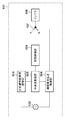
図1は、本実施形態に係る送信器101を示すブロック図である。送信器101は、近距離無線通信と無線電力伝送の両機能を備え、時分割方式に基づいて両機能を動作させて、受信器201との通信と、受信器201への電力供給(送電)を行う。
<< Embodiment 1 >>
(Configuration of transmitter)
FIG. 1 is a block diagram showing a
送信器101は、例えば、発振器102、近距離無線通信制御部103、無線電力伝送制御部104、中央演算装置(CPU)105、切替制御部106、切替部107及びアンテナ108を有する。
The
発振器102は送信器101と受信器201間で近距離無線通信と無線電力伝送を行う搬送波を生成し、近距離無線通信制御部103及び無線電力伝送制御部104へその搬送波を供給する発振器である。この発振器は近距離無線通信と無線電力伝送を行う際に共通で使用される。発振器102は、近距離無線通信と無線電力伝送の搬送波の周波数、例えば13.56MHzで発振している。近距離無線通信制御部103及び無線電力伝送制御部104がこの発振器102から出力された周波数を使う事により、近距離無線通信及び無線電力伝送において周波数及び位相が共通する搬送波の信号を出力することが可能となる。
The
近距離無線通信制御部103は、例えば、受信器201に対してコマンドを生成して送信し、また、受信器201から受信したコマンドの解析を行うことにより、近距離無線通信を制御する。無線電力伝送制御部104は、搬送波の振幅の適正化、受信器201との通信距離などから適正なインピーダンス管理等を行うことにより、無線電力伝送を制御する。
For example, the short-range wireless
中央演算装置105は、近距離無線通信と無線電力伝送を行う期間を制御し、時分割の時間管理を行う。また、中央演算装置105は、近距離無線通信と無線電力伝送との出力搬送波を切り替える切替部107を制御するための切替制御部106に、切替信号を送信する。切替制御部106は、切替信号により、中央演算装置105の時間管理に従って切替部107を動作させ、アンテナ108と、近距離無線通信制御部103又は無線電力伝送制御部104との接続を切り替える。アンテナ108は近距離無線通信と無線電力伝送の搬送波を送信するアンテナであり、近距離無線通信と無線電力伝送の両方の機能で共通に使用される。
The
(受信器の構成)
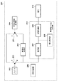
図2は、送信器101との通信を行うと共に、送信器101からの電力の供給を受ける(すなわち、無線電力伝送により受電する)受信器201を示すブロック図である。受信器201は、例えば、アンテナ202、切替部203及び211、近距離無線通信部204、搬送波減衰部205、切替制御部206、電池210及び無線電力伝送受信部212を有する。また、無線電力伝送受信部212は、例えば、整流部207、電荷保持部208、及び充電制御部209を含む。
(Receiver configuration)
FIG. 2 is a block diagram illustrating a
アンテナ202は、送信器101からの、近距離無線通信と無線電力伝送の搬送波を受信する共用アンテナである。切替部203及び211は、アンテナ202で受信した搬送波を近距離無線通信部204(203のA側)に送るか、無線電力伝送受信部212(B側)に送るかを切替える。搬送波減衰部205は、切替部203がB側にある時、アンテナ202で受信した搬送波を、近距離無線通信部204に搬送波を減衰させて入力する。切替制御部206は切替部203及び211の切替制御を行う。
The
整流部207は、アンテナ202で受信した搬送波を整流する。電荷保持部208は、近距離無線通信期間に電荷が途切れるのを防ぐために電荷を維持する。無線電力伝送期間は、受信器201は、受信した搬送波を切替部203のB側を介して整流部207へ供給するため、整流部207の出力には電力が維持される。しかし、近距離無線通信期間になると、切替部203はA側に接続され、整流部207に電力は供給されなくなり、これに伴って整流部から電力が出力されなくなる。このため、電荷保持部208は、整流部207から電力が出力されない間においても電力を維持するために備えられる。近距離無線通信期間が長くなり、電力の供給されない期間が長い場合に対応するために、電荷保持部208の容量を大きく確保してもよい。充電制御部209は、リチウムイオン電池等の電池210への充電を制御する。
The rectifying
(通信システムの構成)
図3は本実施形態における通信システムを示す概略図である。通信システムは、例えば、送信装置301と受信装置302とを含む。送信装置301は、近距離無線通信と無線電力伝送を行う送信器101を含み、例えば非接触で充電を行うための充電装置である。受信装置302は、送信装置301と近距離無線通信と無線電力伝送を行う受信器201を含み、例えば、携帯電話、スマートフォン、デジタルカメラである。受信装置302は、送信装置301の近傍に置かれる(例えば、送信装置301の上に乗せられる)事で、近距離無線通信と無線電力伝送を行う。
(Configuration of communication system)
FIG. 3 is a schematic diagram showing a communication system in the present embodiment. The communication system includes, for example, a
近距離無線通信及び無線電力伝送は、何れも、送信器と受信器との距離が十分短い場合にのみ実行可能となる。近距離無線通信では、受信器は、送信器から通信に用いる搬送波を受信している場合には送信器の通信可能範囲内に存在することとなるため、送信器の通信可能範囲内では、いつでも通信を行う事ができる状態となる。なお、近距離無線通信と無線電力伝送の2つの動作は時分割により行われ、近距離無線通信と無線電力伝送との搬送波の振幅はそれぞれ異なる。 Both near field communication and wireless power transmission can be performed only when the distance between the transmitter and the receiver is sufficiently short. In short-range wireless communication, the receiver is present in the communicable range of the transmitter when receiving a carrier wave used for communication from the transmitter. It becomes a state where it can communicate. Note that the two operations of short-range wireless communication and wireless power transmission are performed in a time-sharing manner, and the carrier wave amplitudes of short-range wireless communication and wireless power transmission are different.
(通信システムの動作)
まず、図4を参照して、1組の送信器及び受信器の間で、どのように近距離無線通信と無線電力伝送とが実行されるかについて説明する。図4は、本実施形態の無線通信における、近距離無線通信と無線電力伝送とを時分割で実行する手法の概要と、その際の搬送波の振幅を示す概略図である。図4に示すように、時分割方式を用いて、近距離無線通信と無線電力伝送とに対して、それぞれを実行するための相異なる時間区間が割り当てられ、それぞれ異なる搬送波が伝送される。また、図4に示すように、近距離無線通信に使用する搬送波の振幅(単位はボルト)はaであり、無線電力伝送に使用する搬送波の振幅(単位はボルト)はbである。
(Operation of communication system)
First, how short-range wireless communication and wireless power transmission are performed between a pair of transmitters and receivers will be described with reference to FIG. FIG. 4 is a schematic diagram illustrating an outline of a technique for performing short-distance wireless communication and wireless power transmission in a time division manner in the wireless communication of the present embodiment, and the amplitude of a carrier wave at that time. As shown in FIG. 4, different time intervals for executing each of the short-range wireless communication and the wireless power transmission are allocated to the short-range wireless communication and the wireless power transmission using a time division method, and different carriers are transmitted. As shown in FIG. 4, the amplitude (unit: volts) of the carrier used for short-range wireless communication is a, and the amplitude (unit: volts) of the carrier used for wireless power transmission is b.
近距離無線通信を行う搬送波の振幅aは、無線電力伝送で使用される搬送波の振幅bよりも小さい。これは、受信器201の近距離無線通信部204に実装されているデバイスの耐圧が低いためである。近距離無線通信のみを搭載した機器は一般に小型である事を求められる事が多く、機器の小型化によりデバイスも比例して小型化され、耐圧も下がってしまう。また、近距離無線通信は小さい振幅の搬送波で通信が可能であるため、通常、耐圧は低くてもよい。このような考えで作られたデバイスを使用しているためデバイスの耐圧は低くなる。一方、無線電力伝送では、大きな振幅の搬送波で電力を伝送しないと、充電に要する時間が多大になってしまう。これは搬送波の振幅と送信できる電力は比例するためである。このような理由により、近距離無線通信と無線電力伝送とは、互いに異なる搬送波を使用する。
The amplitude a of the carrier wave that performs short-range wireless communication is smaller than the amplitude b of the carrier wave used for wireless power transmission. This is because the withstand voltage of the device mounted on the short-range
本実施形態の通信システムは時分割で近距離無線通信と無線電力伝送とを切り替えるため、近距離無線通信の期間は無線電力伝送が途切れる。この場合、図5に示すように、近距離無線通信の期間は、整流部207の電力が途切れ、これに伴い、電池210に対する充電電流が途切れてしまう。電流が途切れない場合には、電池の充電電流と充電電圧との関係を示す特性グラフは図6に示すようになるが、電流が途切れる場合には、特性グラフは図7のようになり、電池の充電可能要件を満たさなくなる。通常は、図7のように電流が途絶えることのないように電流及び電圧を管理して電池210の充電を行う。図7に示すように瞬断等が発生すると、電流がパルス状になり、充電できないのは当然として電池の種類やパルスの形態によっては、例えば電池の故障が生じうる。このため、本実施形態における受信器201は、電荷保持部208を備えることにより、時分割で近距離無線通信と無線電力伝送とを切り替える場合であっても、電池210に入力される電力が瞬断などを起こさないようにしている。
Since the communication system of the present embodiment switches between short-range wireless communication and wireless power transmission in a time division manner, wireless power transmission is interrupted during the short-range wireless communication period. In this case, as shown in FIG. 5, during the short-range wireless communication period, the power of the rectifying
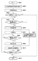
続いて、図9を用いて、送信器101及び受信器201における処理を説明する。図9は、送信器101及び受信器201の動作を示すフローチャートである。受信装置302が送信装置301の上に乗せられる等、受信器201が送信器101の通信可能範囲内に入った場合に、近距離無線通信と無線電力伝送とを実行することができる。したがって、送信器101の通信可能範囲内に受信器201が入った場合に、本処理が開始される(S901)。
Next, processing in the
なお、送信器101の通信可能範囲内に受信器201が存在しない場合、送信器101の切替部107はA側に接続され、近距離無線通信から動作を開始するようにする。また、受信器201は、送信器101の通信可能範囲内に存在していない時は、切替部203及び211が共にA側に接続され、近距離無線通信を行う状態となっている。
When the
送信器101の通信可能範囲内に初めて受信器201が入った場合、近距離無線通信の期間において、送信器101と受信器201とは、近距離無線通信の初期設定を行う(S902)。この設定には、例えば数十msが費やされる。
When the
近距離無線通信の初期設定においては、初期RF磁界確認、RF磁界の発振、ポーリングリクエストコマンド送信、衝突防止処理、初期応答、パラメータ選択、及びデータ通信開始の各処理が実行される。送信器101及び受信器201は、受信器201の近距離無線通信部204が、送信器101が出力する搬送波を受信できない状態から受信できる状態になった時に、その都度この手順を行う。送信器101及び受信器201は、初期設定終了後に近距離無線通信にて充電情報の交換を行う(S903)。
In the initial setting of short-range wireless communication, initial RF magnetic field confirmation, RF magnetic field oscillation, polling request command transmission, collision prevention processing, initial response, parameter selection, and data communication start processing are executed. The
ここで、送信器101の近距離無線通信制御部103は、振幅がaとなるように発振器102からの出力を調整して搬送波として出力する。なお、近距離無線通信制御部103は、近距離無線通信の期間において、受信器201の充電情報等を送受信し、充電の開始、終了、さらには充電電流等の制御を行う。一方、受信器201においては、アンテナ202が受信した搬送波が近距離無線通信部204に入力される。この時の搬送波の振幅は上述の通りaであり、近距離無線通信部204で使用されているデバイスの耐圧を超えないように調整されている。
Here, the short-range wireless
送信器101は、充電情報を交換すると、続いて充電を開始する必要があるかを判定する(S904)。そして、電池210が満充電などの場合で充電を開始する必要がない場合(S904のNO)は、充電を行わずに処理を終了する(S912)。一方、充電を開始する必要がある場合は(S904のYES)、送信器101及び受信器201は、無線電力伝送期間(S905のYES)において無線電力伝送を開始する。無線電力伝送においては、送信器101の切替部107、及び受信器201の切替部203並びに211はB側に切り替えられる(S906)。
After exchanging the charging information, the
無線電力伝送においては、送信器101の無線電力伝送制御部104は、振幅がbとなるように、発振器102からの搬送波を調整して出力する。これにより、受信器201が有する電池210に充電するために、近距離無線通信における搬送波よりも大きい振幅bの搬送波が無線で送信される。
In wireless power transmission, the wireless power
充電は、開始された(S907)後に、無線電力伝送期間の終了(S908のYES)まで継続させる。 Charging is continued after the start (S907) until the end of the wireless power transmission period (YES in S908).
なお、無線電力伝送期間においては、受信器201のアンテナ202を介して受信された搬送波は、搬送波減衰部205に入力され、近距離無線通信部のデバイスの耐圧以下の電力となるように減衰させられる。耐圧以下の電力となった搬送波は、近距離無線通信部204に入力される(S921)。これにより、無線電力伝送期間であっても、耐圧以下の電力を有すると共に周波数と位相が同じ搬送波を、近距離無線通信部204に入力させることができる。一方、無線電力伝送受信部212には振幅がbの搬送波が整流部207に入力される。そして、整流部207は、アンテナ202からの交流電流を直流電流へと変換し、電池210の充電電流として使用する。
In the wireless power transmission period, the carrier wave received via the
無線電力伝送期間が終了すると(S908のYES)、送信器101及び受信器201は、切替部をA側に切替え(S909)、無線電力伝送を終了して近距離無線通信を開始する(S910)。そして、近距離無線通信期間で再び充電情報を交換し、充電が必要ない場合など、充電を停止する場合(S911のYES)は、処理を終了する(S912)。一方、充電を継続する場合(S911のNO)は、無線電力伝送期間の到来(S905のYES)と共に、無線電力伝送を開始する。
When the wireless power transmission period ends (YES in S908), the
このように、本実施形態の受信器201は、無線電力伝送期間においても、近距離無線通信に使用するデバイスに対して、その定格を超えない搬送波の入力を維持する。これに伴い、送信器101との間の近距離無線通信が活性化した状態を維持する事ができているため、2回目以降の近距離無線通信期間に初期化処理を実行する必要はなくなる。この結果、近距離無線通信期間が短縮され、電荷保持部208の容量を小型化する事ができる。また、初期処理を含めた近距離無線通信の期間の電流を保証するだけの電荷を保持できる電荷保持部208を備えた受信器201であれば、同一の期間の長さで初期設定に関わる時間をデータ伝送に使用する事ができ、データ伝送効率が著しく向上する。
Thus, the
このことについて、図8を用いて説明する。近距離無線通信期間のA1で初期処理を行い、A2でデータ伝送を行う。A3では初期処理を行わず、データ伝送のみを行う事ができる。したがって、近距離無線通信を実行するたびに初期処理を実行する場合と比して、A1に相当する時間分をデータ伝送に割り当てることができ、データ伝送の高速化が可能となる。 This will be described with reference to FIG. Initial processing is performed at A1 during the short-range wireless communication period, and data transmission is performed at A2. In A3, initial processing is not performed, and only data transmission can be performed. Therefore, as compared with the case where the initial process is performed every time the short-range wireless communication is performed, the time corresponding to A1 can be allocated to the data transmission, and the data transmission can be speeded up.
なお、本実施形態では時分割における各期間の時間配分は規定していないが、時分割の時間の割合は近距離無線通信の初期設定時に決めてもよい。 In the present embodiment, the time distribution of each period in the time division is not defined, but the ratio of the time division time may be determined at the initial setting of the short-range wireless communication.
<<実施形態2>>
近距離無線通信には様々な方式が提案されており、例えば、送信器101が、受信器201が通信可能範囲内に存在するか否かをポーリングにより確認する方式がある。送信器101は、問い合わせ信号を出力し、これに対して所定時間内に受信器201から応答信号を受信した場合に、通信可能範囲内に受信器201が存在すると判断する。しかし、受信器201は、無線電力伝送期間中には応答信号を返せないおそれがある。この場合、実際は送信器101の近距離無線通信の可能な範囲内に受信器201が存在するにもかかわらず、送信器101が、受信器201が通信可能範囲内に存在しなくなったと判断してしまう場合がある。
<< Embodiment 2 >>
Various methods have been proposed for short-range wireless communication. For example, there is a method in which the
本実施形態では、このようなポーリング方式によって受信器201が通信可能範囲内に存在するかを判定する手法に、送信器101を対応させる。本実施形態に係る送信器101の構成図を図10に示す。本実施形態に係る送信器101は、実施形態1で示した送信器101と比べて、切替部107に代えて切替部1101及び1102を有すると共に、ポーリング応答部1103をさらに有する。
In this embodiment, the
本実施形態においては、近距離無線通信制御部103は、近距離無線通信期間であるか否かに関わらず問い合わせ信号を出力する。そして、ポーリング応答部1103は、近距離無線通信制御部103が出力した問い合わせ信号を受信すると、それに対する応答信号を生成して出力する。すなわち、ポーリング応答部1103は、近距離無線通信制御部103が出力した問い合わせ信号に対して、疑似的な応答信号を返す機能部である。
In the present embodiment, the short-range wireless
切替部1101及び1102は、近距離無線通信期間においてはA側へ接続され、無線電力伝送期間においてはB側へ接続される。これにより、近距離無線通信制御部103が出力する問い合わせ信号は、近距離無線通信期間においてはアンテナ108を介して送出され、無線電力伝送期間においてはポーリング応答部へ出力される。したがって、受信器201が送信器101の通信可能範囲に存在する場合、近距離無線通信制御部103は、近距離無線通信期間においては受信器201から応答信号を受信し、無線電力伝送期間においてはポーリング応答部1103から応答信号を受信する。
これにより、送信器101は、無線電力伝送期間において、通信可能範囲内に存在する受信器201が応答信号を送信できない状態になったとしても、通信可能範囲内に受信器201が存在すると判定することができるようになる。また、これにより、初期処理を都度やりなおす必要がなくなるため、近距離無線通信と無線電力伝送とを時分割で実行する場合に、2回目以降の近距離無線通信の初期処理を省略することができるようになり、近距離無線通信期間を短縮する事ができる。また、初期処理を省略することにより、初期処理に費やすはずだった時間をデータ伝送に費やすことができるため、伝送効率が著しく向上することが可能となる。
Thus, the
また、中央演算装置105は、近距離無線通信制御部103の問い合わせ信号の出力を制御してもよい。この場合、中央演算装置105は、近距離無線通信と無線電力伝送の時分割期間を管理しているため、無線電力伝送期間においては問い合わせ信号の出力を停止する事ができる。これにより、無線電力伝送期間において問い合わせ信号を出力しなくなる、すなわち問い合わせを行うことがなくなるため、受信器201が通信可能範囲内に存在しなくなったと判断することがなくなる。したがって、このような形態とすることにより、ポーリング応答部1103を省略することができる。
The
<<その他の実施形態>>
また、本発明は、以下の処理を実行することによっても実現される。即ち、上述した実施形態の機能を実現するソフトウェア(プログラム)を、ネットワーク又は各種記憶媒体を介してシステム或いは装置に供給し、そのシステム或いは装置のコンピュータ(またはCPUやMPU等)がプログラムを読み出して実行する処理である。
<< Other Embodiments >>
The present invention can also be realized by executing the following processing. That is, software (program) that realizes the functions of the above-described embodiments is supplied to a system or apparatus via a network or various storage media, and a computer (or CPU, MPU, or the like) of the system or apparatus reads the program. It is a process to be executed.
Claims (9)
前記送信装置は、
前記無線通信と前記無線電力伝送とで用いられる搬送波を供給する供給手段と、
前記供給手段により供給された搬送波を用いて前記受信装置へ前記無線通信で信号を送信する送信手段と、
前記供給手段により供給された搬送波を用いて前記受信装置へ前記無線電力伝送により送電する送電手段と、
を有し、
前記受信装置は、
前記搬送波を用いて前記送信装置から前記無線通信で送信された信号を受信する受信手段と、
前記搬送波を用いて前記送信装置から前記無線電力伝送により送電された電力を受電する受電手段と、
前記送信装置からの前記搬送波に応じた信号を減衰させ、当該減衰済みの信号を前記受信手段へ供給する減衰手段と、
前記無線通信を実行する期間は、前記送信装置からの前記搬送波に応じた信号を前記受信手段に供給すると共に、前記無線電力伝送を実行する期間は、前記送信装置からの前記搬送波に応じた信号を前記減衰手段に対して供給する供給手段と、
を有することを特徴とする通信システム。 A communication system that executes wireless communication and wireless power transmission in a time division manner between a transmission device and a reception device,
The transmitter is
Supply means for supplying a carrier wave used in the wireless communication and the wireless power transmission;
Transmitting means for transmitting a signal in the wireless communication to the receiving device using the carrier wave supplied by the supplying means;
Power transmission means for transmitting power to the receiving device by the wireless power transmission using the carrier wave supplied by the supply means;
Have
The receiving device is:
Receiving means for receiving a signal transmitted by the wireless communication from the transmitting device using the carrier;
Power receiving means for receiving power transmitted by the wireless power transmission from the transmission device using the carrier wave;
Attenuating means for attenuating a signal corresponding to the carrier wave from the transmitting device and supplying the attenuated signal to the receiving means;
During the period for executing the wireless communication, a signal corresponding to the carrier wave from the transmitting apparatus is supplied to the receiving means, and during the period for executing the wireless power transmission, a signal corresponding to the carrier wave from the transmitting apparatus is provided. Supply means for supplying to the damping means;
Communication system, characterized in that the have a.
搬送波を用いて前記送信装置から前記無線通信により送信された信号を受信する受信手段と、
搬送波を用いて前記送信装置から前記無線電力伝送により送電された電力を受電する受電手段と、
前記送信装置からの前記搬送波に応じた信号を減衰させ、当該減衰済みの信号を前記受信手段へ供給する減衰手段と、
前記無線通信を実行する期間は、前記送信装置からの前記搬送波に応じた信号を前記受信手段に供給すると共に、前記無線電力伝送を実行する期間は、前記送信装置からの前記搬送波に応じた信号を前記減衰手段に対して供給する供給手段と、
を有することを特徴とする受信装置。 A receiving device that switches between wireless communication and wireless power transmission in a time-sharing manner with a transmitting device,
Receiving means for receiving a signal transmitted by the wireless communication from the transmitting device using a carrier wave;
Power receiving means for receiving power transmitted by the wireless power transmission from the transmission device using a carrier wave;
Attenuating means for attenuating a signal corresponding to the carrier wave from the transmitting device and supplying the attenuated signal to the receiving means;
During the period for executing the wireless communication, a signal corresponding to the carrier wave from the transmitting apparatus is supplied to the receiving means, and during the period for executing the wireless power transmission, a signal corresponding to the carrier wave from the transmitting apparatus is provided. Supply means for supplying to the damping means;
A receiving apparatus comprising:
ことを特徴とする請求項2に記載の受信装置。 The receiving device according to claim 2.
前記無線通信と前記無線電力伝送とで用いられる搬送波を供給する供給手段と、
前記供給手段により供給された搬送波を用いて前記受信装置へ前記無線通信で信号を送信する送信手段と、
前記供給手段により供給された搬送波を用いて前記受信装置へ前記無線電力伝送により送電する送電手段と、
前記受信装置が前記無線通信の通信可能範囲内に存在するかを問い合わせるために前記送信手段により送信された問い合わせ信号に対する応答信号の有無に基づいて前記受信装置の存在を判定する判定手段と、
前記無線電力伝送を実行する期間において前記送信手段により問い合わせ信号が送信された場合、前記問い合わせ信号に対する応答信号を前記判定手段へ提供する応答手段と、
を有することを特徴とする送信装置。 A transmission device that switches between wireless communication and wireless power transmission in a time-sharing manner with a receiving device,
Supply means for supplying a carrier wave used in the wireless communication and the wireless power transmission;
Transmitting means for transmitting a signal in the wireless communication to the receiving device using the carrier wave supplied by the supplying means;
Power transmission means for transmitting power to the receiving device by the wireless power transmission using the carrier wave supplied by the supply means;
A determination unit that determines the presence of the reception device based on the presence or absence of a response signal to the inquiry signal transmitted by the transmission unit in order to inquire whether the reception device is within a communicable range of the wireless communication;
A response means for providing a response signal to the inquiry signal to the determination means when an inquiry signal is transmitted by the transmission means in a period of executing the wireless power transmission;
Transmitting device comprising a Turkey which have a.
をさらに有することを特徴とする請求項4に記載の送信装置。 The inquiry signal is transmitted to the receiving device during a period of executing the wireless communication, and is output to the response means during a period of executing the wireless power transmission. Switching means for switching the output destination of the signal,
The transmitter according to claim 4 , further comprising:
前記無線通信を実行する期間は、前記送信装置からの前記搬送波に応じた信号が前記受信手段に供給されると共に、前記無線電力伝送を実行する期間は、前記送信装置からの前記搬送波に応じた信号が前記減衰手段に対して供給されるように制御する供給工程を有する、
ことを特徴とする制御方法。
Receiving means for receiving a signal transmitted by wireless communication from a transmitting apparatus using a carrier wave; receiving means for receiving power transmitted by wireless power transmission from the transmitting apparatus using a carrier wave; and Attenuating means for attenuating a signal corresponding to a carrier wave and supplying the attenuated signal to the receiving means , and switching between the wireless communication and the wireless power transmission in a time-sharing manner with the transmitting device. A control method in a receiving device to perform,
During the period for executing the wireless communication, a signal corresponding to the carrier wave from the transmitting apparatus is supplied to the receiving unit, and the period for executing the wireless power transmission corresponds to the carrier wave from the transmitting apparatus. A supply step for controlling a signal to be supplied to the attenuation means;
A control method characterized by that.
前記無線電力伝送を実行する期間において前記送信手段により問い合わせ信号が送信された場合、前記問い合わせ信号に対する応答信号を前記判定手段へ提供する応答工程を有する、
ことを特徴とする制御方法。 A method for controlling a transmitting apparatus that performs switching between wireless communication and wireless power transmission in a time-sharing manner with a receiving apparatus, wherein the transmitting apparatus supplies a carrier wave used in the wireless communication and the wireless power transmission Supply means for transmitting, transmitting means for transmitting a signal to the receiving apparatus using the carrier wave supplied by the supplying means, and wireless power to the receiving apparatus using the carrier wave supplied by the supplying means. Existence of the receiving device based on the presence or absence of a response signal to the inquiry signal transmitted by the transmitting unit to inquire whether the receiving device is within the communicable range of the wireless communication, Determining means for determining
A response step of providing a response signal for the inquiry signal to the determination means when an inquiry signal is transmitted by the transmission means in a period of executing the wireless power transmission ;
A control method characterized by that.
Priority Applications (1)
| Application Number | Priority Date | Filing Date | Title |
|---|---|---|---|
| JP2012225366A JP6053442B2 (en) | 2012-10-10 | 2012-10-10 | COMMUNICATION SYSTEM, RECEPTION DEVICE, TRANSMISSION DEVICE, CONTROL METHOD, AND PROGRAM |
Applications Claiming Priority (1)
| Application Number | Priority Date | Filing Date | Title |
|---|---|---|---|
| JP2012225366A JP6053442B2 (en) | 2012-10-10 | 2012-10-10 | COMMUNICATION SYSTEM, RECEPTION DEVICE, TRANSMISSION DEVICE, CONTROL METHOD, AND PROGRAM |
Publications (3)
| Publication Number | Publication Date |
|---|---|
| JP2014079091A JP2014079091A (en) | 2014-05-01 |
| JP2014079091A5 JP2014079091A5 (en) | 2015-11-05 |
| JP6053442B2 true JP6053442B2 (en) | 2016-12-27 |
Family
ID=50783961
Family Applications (1)
| Application Number | Title | Priority Date | Filing Date |
|---|---|---|---|
| JP2012225366A Active JP6053442B2 (en) | 2012-10-10 | 2012-10-10 | COMMUNICATION SYSTEM, RECEPTION DEVICE, TRANSMISSION DEVICE, CONTROL METHOD, AND PROGRAM |
Country Status (1)
| Country | Link |
|---|---|
| JP (1) | JP6053442B2 (en) |
Families Citing this family (12)
| Publication number | Priority date | Publication date | Assignee | Title |
|---|---|---|---|---|
| US9608473B2 (en) * | 2014-07-07 | 2017-03-28 | Htc Corporation | Near field communication and wireless charging device and switching method using the same |
| JP6512799B2 (en) * | 2014-11-27 | 2019-05-15 | キヤノン株式会社 | POWER SUPPLY DEVICE, CONTROL METHOD, AND PROGRAM |
| JP6440197B2 (en) * | 2015-03-31 | 2018-12-19 | トッパン・フォームズ株式会社 | Non-contact power supply system and power transmitter |
| WO2017184083A1 (en) * | 2016-04-22 | 2017-10-26 | Agency For Science, Technology And Research | Synchronized time-division wireless power transfer for multiple voltage applications |
| JP6444940B2 (en) * | 2016-05-17 | 2018-12-26 | ファナック株式会社 | Workpiece holding system |
| JP6721459B2 (en) * | 2016-08-25 | 2020-07-15 | ラピスセミコンダクタ株式会社 | Power receiving device, power transmitting device, power feeding system, and power receiving method |
| JP6730135B2 (en) * | 2016-08-25 | 2020-07-29 | ラピスセミコンダクタ株式会社 | Power transmission device, power reception device, power supply system, and power transmission method |
| JP6923308B2 (en) | 2016-11-22 | 2021-08-18 | ラピスセミコンダクタ株式会社 | Wireless power supply device, wireless power receiving device, wireless power transmission system and wireless power supply method |
| JP7187135B2 (en) * | 2017-05-16 | 2022-12-12 | ラピスセミコンダクタ株式会社 | Wireless power receiving device, wireless power supply device, wireless power transmission system, and excessive magnetic field protection method for wireless power receiving device |
| EP3671891A4 (en) * | 2017-08-14 | 2021-04-14 | Koki Holdings Co., Ltd. | Battery pack and electrical device |
| JP6630712B2 (en) * | 2017-10-30 | 2020-01-15 | 京セラ株式会社 | Measurement method, measurement program, and measurement device |
| JP7115723B2 (en) | 2018-01-04 | 2022-08-09 | ラピスセミコンダクタ株式会社 | Semiconductor equipment and semiconductor modules |
Family Cites Families (3)
| Publication number | Priority date | Publication date | Assignee | Title |
|---|---|---|---|---|
| JPH1032526A (en) * | 1996-07-18 | 1998-02-03 | Omron Corp | Identification system |
| JP4657657B2 (en) * | 2004-09-03 | 2011-03-23 | パナソニック株式会社 | Reader / writer and wireless tag system |
| JP5476194B2 (en) * | 2010-04-08 | 2014-04-23 | Necトーキン株式会社 | Non-contact power transmission and communication system, power transmission device and power reception device |
-
2012
- 2012-10-10 JP JP2012225366A patent/JP6053442B2/en active Active
Also Published As
| Publication number | Publication date |
|---|---|
| JP2014079091A (en) | 2014-05-01 |
Similar Documents
| Publication | Publication Date | Title |
|---|---|---|
| JP6053442B2 (en) | COMMUNICATION SYSTEM, RECEPTION DEVICE, TRANSMISSION DEVICE, CONTROL METHOD, AND PROGRAM | |
| EP2713472B1 (en) | Power receiving device having device detection and power transfer capabilities | |
| JP5637641B2 (en) | Wireless power charging method and apparatus | |
| US8213862B2 (en) | Headset charge via short-range RF communication | |
| EP3588792A1 (en) | Reducing power consumption for connection establishment in near field communication systems | |
| US20130214735A1 (en) | Wireless charging apparatus and method | |
| US20140094116A1 (en) | Power Transmitting Device Having Device Discovery and Power Transfer Capabilities | |
| CN109121446A (en) | Power transmitting apparatus, power receiving system, control method and program | |
| US20170202035A1 (en) | Wireless communication terminal, wireless communication system, and storage medium storing wireless communication program | |
| EP3012940A1 (en) | Wireless charging device and method | |
| KR20130114473A (en) | Apparatus and method for controlling wireless power transmission | |
| US20170154327A1 (en) | Mobile Payment Method and Apparatus and Near Field Communication Device | |
| US10651692B2 (en) | Power transmission device, power reception device, power supply system, and power transmission method | |
| EP2981000A1 (en) | Portable satellite communication apparatus | |
| JP2016111792A (en) | Power reception device, power reception device control method, and program | |
| CN103326749B (en) | A kind of control method of NFC radio frequency communication, Apparatus and system | |
| US20140273842A1 (en) | Communication system, communication apparatus, and communication method | |
| WO2013081763A1 (en) | Modified connection establishment for reducing power consumption in near field communication systems | |
| CN107785951B (en) | Power receiving device, power transmitting device, power supply system, and power receiving method | |
| JP2015154111A (en) | communication device, control method, and program | |
| JP2019512977A (en) | Method for routing data frames, near field communication controller and terminal | |
| CN110169090B (en) | Information transmission method, device and storage medium | |
| CN110419141B (en) | Method for charging battery through near field communication | |
| KR101515480B1 (en) | Wireless power transfer method between devices using NFC | |
| CN103765791B (en) | Near field communication radio frequency discovery control, device and terminal equipment |
Legal Events
| Date | Code | Title | Description |
|---|---|---|---|
| A521 | Request for written amendment filed |
Free format text: JAPANESE INTERMEDIATE CODE: A523 Effective date: 20150914 |
|
| A621 | Written request for application examination |
Free format text: JAPANESE INTERMEDIATE CODE: A621 Effective date: 20150914 |
|
| A131 | Notification of reasons for refusal |
Free format text: JAPANESE INTERMEDIATE CODE: A131 Effective date: 20160425 |
|
| A977 | Report on retrieval |
Free format text: JAPANESE INTERMEDIATE CODE: A971007 Effective date: 20160428 |
|
| A521 | Request for written amendment filed |
Free format text: JAPANESE INTERMEDIATE CODE: A523 Effective date: 20160617 |
|
| A131 | Notification of reasons for refusal |
Free format text: JAPANESE INTERMEDIATE CODE: A131 Effective date: 20160905 |
|
| A521 | Request for written amendment filed |
Free format text: JAPANESE INTERMEDIATE CODE: A523 Effective date: 20161013 |
|
| TRDD | Decision of grant or rejection written | ||
| A01 | Written decision to grant a patent or to grant a registration (utility model) |
Free format text: JAPANESE INTERMEDIATE CODE: A01 Effective date: 20161031 |
|
| A61 | First payment of annual fees (during grant procedure) |
Free format text: JAPANESE INTERMEDIATE CODE: A61 Effective date: 20161129 |
|
| R151 | Written notification of patent or utility model registration |
Ref document number: 6053442 Country of ref document: JP Free format text: JAPANESE INTERMEDIATE CODE: R151 |