JP6049637B2 - Radiopaque embolic particles - Google Patents
Radiopaque embolic particles Download PDFInfo
- Publication number
- JP6049637B2 JP6049637B2 JP2013550965A JP2013550965A JP6049637B2 JP 6049637 B2 JP6049637 B2 JP 6049637B2 JP 2013550965 A JP2013550965 A JP 2013550965A JP 2013550965 A JP2013550965 A JP 2013550965A JP 6049637 B2 JP6049637 B2 JP 6049637B2
- Authority
- JP
- Japan
- Prior art keywords
- mole fraction
- particulate material
- material according
- composition
- present
- Prior art date
- Legal status (The legal status is an assumption and is not a legal conclusion. Google has not performed a legal analysis and makes no representation as to the accuracy of the status listed.)
- Active
Links
- 239000002245 particle Substances 0.000 title description 68
- 230000003073 embolic effect Effects 0.000 title description 36
- 239000011236 particulate material Substances 0.000 claims description 92
- 239000000203 mixture Substances 0.000 claims description 61
- 239000008187 granular material Substances 0.000 claims description 32
- 229910021193 La 2 O 3 Inorganic materials 0.000 claims description 30
- 229910010413 TiO 2 Inorganic materials 0.000 claims description 29
- 229910004298 SiO 2 Inorganic materials 0.000 claims description 24
- 230000010102 embolization Effects 0.000 claims description 19
- 230000001225 therapeutic effect Effects 0.000 claims description 17
- 229920000642 polymer Polymers 0.000 claims description 16
- 239000000126 substance Substances 0.000 claims description 13
- 206010053648 Vascular occlusion Diseases 0.000 claims description 10
- 208000021331 vascular occlusion disease Diseases 0.000 claims description 10
- 206010046798 Uterine leiomyoma Diseases 0.000 claims description 8
- 208000009443 Vascular Malformations Diseases 0.000 claims description 7
- 239000011248 coating agent Substances 0.000 claims description 7
- 238000000576 coating method Methods 0.000 claims description 7
- 201000010260 leiomyoma Diseases 0.000 claims description 7
- 210000000056 organ Anatomy 0.000 claims description 7
- 230000004962 physiological condition Effects 0.000 claims description 7
- 208000032843 Hemorrhage Diseases 0.000 claims description 6
- 229910019142 PO4 Inorganic materials 0.000 claims description 6
- 229910000323 aluminium silicate Inorganic materials 0.000 claims description 6
- 208000034158 bleeding Diseases 0.000 claims description 6
- 230000000740 bleeding effect Effects 0.000 claims description 6
- HNPSIPDUKPIQMN-UHFFFAOYSA-N dioxosilane;oxo(oxoalumanyloxy)alumane Chemical compound O=[Si]=O.O=[Al]O[Al]=O HNPSIPDUKPIQMN-UHFFFAOYSA-N 0.000 claims description 6
- NBIIXXVUZAFLBC-UHFFFAOYSA-K phosphate Chemical compound [O-]P([O-])([O-])=O NBIIXXVUZAFLBC-UHFFFAOYSA-K 0.000 claims description 6
- 239000010452 phosphate Substances 0.000 claims description 6
- 238000002271 resection Methods 0.000 claims description 6
- 229920001983 poloxamer Polymers 0.000 claims description 5
- RVGRUAULSDPKGF-UHFFFAOYSA-N Poloxamer Chemical compound C1CO1.CC1CO1 RVGRUAULSDPKGF-UHFFFAOYSA-N 0.000 claims description 4
- 230000010109 chemoembolization Effects 0.000 claims description 4
- 229920001577 copolymer Polymers 0.000 claims description 4
- 229960000502 poloxamer Drugs 0.000 claims description 4
- 201000007954 uterine fibroid Diseases 0.000 claims description 4
- 239000004615 ingredient Substances 0.000 claims description 3
- 239000011159 matrix material Substances 0.000 claims description 3
- 208000010579 uterine corpus leiomyoma Diseases 0.000 claims description 3
- 239000000306 component Substances 0.000 description 47
- CPLXHLVBOLITMK-UHFFFAOYSA-N Magnesium oxide Chemical compound [Mg]=O CPLXHLVBOLITMK-UHFFFAOYSA-N 0.000 description 43
- XLOMVQKBTHCTTD-UHFFFAOYSA-N Zinc monoxide Chemical compound [Zn]=O XLOMVQKBTHCTTD-UHFFFAOYSA-N 0.000 description 38
- 239000011521 glass Substances 0.000 description 34
- 239000000463 material Substances 0.000 description 32
- 150000002500 ions Chemical class 0.000 description 28
- 239000011734 sodium Substances 0.000 description 28
- 230000000694 effects Effects 0.000 description 23
- 239000000395 magnesium oxide Substances 0.000 description 22
- 239000000284 extract Substances 0.000 description 20
- 239000010936 titanium Substances 0.000 description 19
- 239000011787 zinc oxide Substances 0.000 description 19
- 239000002609 medium Substances 0.000 description 18
- 210000004027 cell Anatomy 0.000 description 17
- 230000003833 cell viability Effects 0.000 description 17
- 238000012360 testing method Methods 0.000 description 17
- 210000001519 tissue Anatomy 0.000 description 17
- 239000011575 calcium Substances 0.000 description 16
- 238000011534 incubation Methods 0.000 description 16
- 239000000523 sample Substances 0.000 description 16
- 238000004400 29Si cross polarisation magic angle spinning Methods 0.000 description 14
- 239000000243 solution Substances 0.000 description 13
- XLYOFNOQVPJJNP-UHFFFAOYSA-N water Substances O XLYOFNOQVPJJNP-UHFFFAOYSA-N 0.000 description 13
- 102000003855 L-lactate dehydrogenase Human genes 0.000 description 11
- 108700023483 L-lactate dehydrogenases Proteins 0.000 description 11
- 238000005481 NMR spectroscopy Methods 0.000 description 11
- 239000011859 microparticle Substances 0.000 description 11
- VYPSYNLAJGMNEJ-UHFFFAOYSA-N Silicium dioxide Chemical compound O=[Si]=O VYPSYNLAJGMNEJ-UHFFFAOYSA-N 0.000 description 10
- 239000011777 magnesium Substances 0.000 description 10
- BASFCYQUMIYNBI-UHFFFAOYSA-N platinum Chemical compound [Pt] BASFCYQUMIYNBI-UHFFFAOYSA-N 0.000 description 10
- 101000720655 Homo sapiens Oxysterol-binding protein-related protein 11 Proteins 0.000 description 9
- 102100025875 Oxysterol-binding protein-related protein 11 Human genes 0.000 description 9
- 238000006243 chemical reaction Methods 0.000 description 9
- 239000003795 chemical substances by application Substances 0.000 description 9
- 238000000113 differential scanning calorimetry Methods 0.000 description 9
- 238000002474 experimental method Methods 0.000 description 9
- 230000003993 interaction Effects 0.000 description 9
- 239000000758 substrate Substances 0.000 description 9
- 238000002441 X-ray diffraction Methods 0.000 description 8
- 238000000540 analysis of variance Methods 0.000 description 8
- QVGXLLKOCUKJST-UHFFFAOYSA-N atomic oxygen Chemical compound [O] QVGXLLKOCUKJST-UHFFFAOYSA-N 0.000 description 8
- 238000011156 evaluation Methods 0.000 description 8
- 238000005259 measurement Methods 0.000 description 8
- 239000001301 oxygen Substances 0.000 description 8
- 229910052760 oxygen Inorganic materials 0.000 description 8
- 239000000843 powder Substances 0.000 description 8
- 101100462341 Homo sapiens OSBPL2 gene Proteins 0.000 description 7
- 101000992392 Homo sapiens Oxysterol-binding protein-related protein 6 Proteins 0.000 description 7
- 101150054848 Osbpl9 gene Proteins 0.000 description 7
- 102100025925 Oxysterol-binding protein-related protein 2 Human genes 0.000 description 7
- 102100032149 Oxysterol-binding protein-related protein 6 Human genes 0.000 description 7
- 102100032162 Oxysterol-binding protein-related protein 9 Human genes 0.000 description 7
- 101100518421 Schizosaccharomyces pombe (strain 972 / ATCC 24843) orc2 gene Proteins 0.000 description 7
- 101100261632 Zea mays TSB2 gene Proteins 0.000 description 7
- 230000015556 catabolic process Effects 0.000 description 7
- 239000000919 ceramic Substances 0.000 description 7
- 238000002983 circular dichroism Methods 0.000 description 7
- 239000002872 contrast media Substances 0.000 description 7
- 239000013078 crystal Substances 0.000 description 7
- 238000006731 degradation reaction Methods 0.000 description 7
- 238000013461 design Methods 0.000 description 7
- 238000010790 dilution Methods 0.000 description 7
- 239000012895 dilution Substances 0.000 description 7
- 238000001727 in vivo Methods 0.000 description 7
- 238000002347 injection Methods 0.000 description 7
- 239000007924 injection Substances 0.000 description 7
- 238000002843 lactate dehydrogenase assay Methods 0.000 description 7
- 238000001228 spectrum Methods 0.000 description 7
- 239000011701 zinc Substances 0.000 description 7
- 241001465754 Metazoa Species 0.000 description 6
- 238000007792 addition Methods 0.000 description 6
- 238000003556 assay Methods 0.000 description 6
- 210000004369 blood Anatomy 0.000 description 6
- 239000008280 blood Substances 0.000 description 6
- 229910002091 carbon monoxide Inorganic materials 0.000 description 6
- 238000004113 cell culture Methods 0.000 description 6
- 210000002950 fibroblast Anatomy 0.000 description 6
- 210000004623 platelet-rich plasma Anatomy 0.000 description 6
- 238000002360 preparation method Methods 0.000 description 6
- 239000000047 product Substances 0.000 description 6
- 241000894007 species Species 0.000 description 6
- 230000000007 visual effect Effects 0.000 description 6
- 239000006144 Dulbecco’s modified Eagle's medium Substances 0.000 description 5
- 102000008946 Fibrinogen Human genes 0.000 description 5
- 108010049003 Fibrinogen Proteins 0.000 description 5
- 101000854060 Homo sapiens Oxygen-regulated protein 1 Proteins 0.000 description 5
- 101000720693 Homo sapiens Oxysterol-binding protein-related protein 1 Proteins 0.000 description 5
- 231100000416 LDH assay Toxicity 0.000 description 5
- 206010028980 Neoplasm Diseases 0.000 description 5
- 241000283973 Oryctolagus cuniculus Species 0.000 description 5
- 102100025924 Oxysterol-binding protein-related protein 1 Human genes 0.000 description 5
- FAPWRFPIFSIZLT-UHFFFAOYSA-M Sodium chloride Chemical compound [Na+].[Cl-] FAPWRFPIFSIZLT-UHFFFAOYSA-M 0.000 description 5
- 239000012298 atmosphere Substances 0.000 description 5
- 239000007857 degradation product Substances 0.000 description 5
- 229940012952 fibrinogen Drugs 0.000 description 5
- 230000006870 function Effects 0.000 description 5
- 229910052697 platinum Inorganic materials 0.000 description 5
- 239000013641 positive control Substances 0.000 description 5
- 230000004044 response Effects 0.000 description 5
- 239000000377 silicon dioxide Substances 0.000 description 5
- 239000011780 sodium chloride Substances 0.000 description 5
- 238000005004 MAS NMR spectroscopy Methods 0.000 description 4
- XUIMIQQOPSSXEZ-UHFFFAOYSA-N Silicon Chemical compound [Si] XUIMIQQOPSSXEZ-UHFFFAOYSA-N 0.000 description 4
- 238000004458 analytical method Methods 0.000 description 4
- 230000008901 benefit Effects 0.000 description 4
- 210000004204 blood vessel Anatomy 0.000 description 4
- 238000011088 calibration curve Methods 0.000 description 4
- 201000011510 cancer Diseases 0.000 description 4
- 230000008859 change Effects 0.000 description 4
- 231100000135 cytotoxicity Toxicity 0.000 description 4
- 230000003013 cytotoxicity Effects 0.000 description 4
- 238000004090 dissolution Methods 0.000 description 4
- 238000002149 energy-dispersive X-ray emission spectroscopy Methods 0.000 description 4
- 230000007794 irritation Effects 0.000 description 4
- 229920001606 poly(lactic acid-co-glycolic acid) Polymers 0.000 description 4
- 229910052710 silicon Inorganic materials 0.000 description 4
- 239000010703 silicon Substances 0.000 description 4
- 229910052708 sodium Inorganic materials 0.000 description 4
- 238000004611 spectroscopical analysis Methods 0.000 description 4
- 239000000725 suspension Substances 0.000 description 4
- YMWUJEATGCHHMB-UHFFFAOYSA-N Dichloromethane Chemical compound ClCCl YMWUJEATGCHHMB-UHFFFAOYSA-N 0.000 description 3
- 208000012671 Gastrointestinal haemorrhages Diseases 0.000 description 3
- 101000992396 Homo sapiens Oxysterol-binding protein-related protein 3 Proteins 0.000 description 3
- 101000992390 Homo sapiens Oxysterol-binding protein-related protein 7 Proteins 0.000 description 3
- 238000000134 MTT assay Methods 0.000 description 3
- FYYHWMGAXLPEAU-UHFFFAOYSA-N Magnesium Chemical compound [Mg] FYYHWMGAXLPEAU-UHFFFAOYSA-N 0.000 description 3
- 102100032154 Oxysterol-binding protein-related protein 3 Human genes 0.000 description 3
- 102100032150 Oxysterol-binding protein-related protein 7 Human genes 0.000 description 3
- HEMHJVSKTPXQMS-UHFFFAOYSA-M Sodium hydroxide Chemical compound [OH-].[Na+] HEMHJVSKTPXQMS-UHFFFAOYSA-M 0.000 description 3
- 208000027418 Wounds and injury Diseases 0.000 description 3
- 238000002835 absorbance Methods 0.000 description 3
- 238000013459 approach Methods 0.000 description 3
- 230000015572 biosynthetic process Effects 0.000 description 3
- 239000003153 chemical reaction reagent Substances 0.000 description 3
- 229940039231 contrast media Drugs 0.000 description 3
- 230000006378 damage Effects 0.000 description 3
- 238000013401 experimental design Methods 0.000 description 3
- 239000000706 filtrate Substances 0.000 description 3
- 208000030304 gastrointestinal bleeding Diseases 0.000 description 3
- 230000009477 glass transition Effects 0.000 description 3
- 239000002241 glass-ceramic Substances 0.000 description 3
- 230000005484 gravity Effects 0.000 description 3
- 208000014674 injury Diseases 0.000 description 3
- 229910052746 lanthanum Inorganic materials 0.000 description 3
- FZLIPJUXYLNCLC-UHFFFAOYSA-N lanthanum atom Chemical compound [La] FZLIPJUXYLNCLC-UHFFFAOYSA-N 0.000 description 3
- 229910052749 magnesium Inorganic materials 0.000 description 3
- 230000002503 metabolic effect Effects 0.000 description 3
- 229910052751 metal Inorganic materials 0.000 description 3
- 238000000034 method Methods 0.000 description 3
- 230000000877 morphologic effect Effects 0.000 description 3
- 239000013642 negative control Substances 0.000 description 3
- 239000004033 plastic Substances 0.000 description 3
- 229920001992 poloxamer 407 Polymers 0.000 description 3
- 102000004169 proteins and genes Human genes 0.000 description 3
- 108090000623 proteins and genes Proteins 0.000 description 3
- 238000011002 quantification Methods 0.000 description 3
- 230000009467 reduction Effects 0.000 description 3
- 230000002885 thrombogenetic effect Effects 0.000 description 3
- IJGRMHOSHXDMSA-UHFFFAOYSA-N Atomic nitrogen Chemical compound N#N IJGRMHOSHXDMSA-UHFFFAOYSA-N 0.000 description 2
- 108091003079 Bovine Serum Albumin Proteins 0.000 description 2
- OYPRJOBELJOOCE-UHFFFAOYSA-N Calcium Chemical compound [Ca] OYPRJOBELJOOCE-UHFFFAOYSA-N 0.000 description 2
- VTYYLEPIZMXCLO-UHFFFAOYSA-L Calcium carbonate Chemical compound [Ca+2].[O-]C([O-])=O VTYYLEPIZMXCLO-UHFFFAOYSA-L 0.000 description 2
- DGAQECJNVWCQMB-PUAWFVPOSA-M Ilexoside XXIX Chemical compound C[C@@H]1CC[C@@]2(CC[C@@]3(C(=CC[C@H]4[C@]3(CC[C@@H]5[C@@]4(CC[C@@H](C5(C)C)OS(=O)(=O)[O-])C)C)[C@@H]2[C@]1(C)O)C)C(=O)O[C@H]6[C@@H]([C@H]([C@@H]([C@H](O6)CO)O)O)O.[Na+] DGAQECJNVWCQMB-PUAWFVPOSA-M 0.000 description 2
- 231100000002 MTT assay Toxicity 0.000 description 2
- 239000004793 Polystyrene Substances 0.000 description 2
- 208000001647 Renal Insufficiency Diseases 0.000 description 2
- CDBYLPFSWZWCQE-UHFFFAOYSA-L Sodium Carbonate Chemical compound [Na+].[Na+].[O-]C([O-])=O CDBYLPFSWZWCQE-UHFFFAOYSA-L 0.000 description 2
- GWEVSGVZZGPLCZ-UHFFFAOYSA-N Titan oxide Chemical compound O=[Ti]=O GWEVSGVZZGPLCZ-UHFFFAOYSA-N 0.000 description 2
- RTAQQCXQSZGOHL-UHFFFAOYSA-N Titanium Chemical compound [Ti] RTAQQCXQSZGOHL-UHFFFAOYSA-N 0.000 description 2
- 206010053476 Traumatic haemorrhage Diseases 0.000 description 2
- 238000010521 absorption reaction Methods 0.000 description 2
- 230000001464 adherent effect Effects 0.000 description 2
- 230000025164 anoikis Effects 0.000 description 2
- 229920000249 biocompatible polymer Polymers 0.000 description 2
- 239000000872 buffer Substances 0.000 description 2
- 229910052791 calcium Inorganic materials 0.000 description 2
- 238000013043 cell viability test Methods 0.000 description 2
- 238000012512 characterization method Methods 0.000 description 2
- 238000001142 circular dichroism spectrum Methods 0.000 description 2
- 230000035602 clotting Effects 0.000 description 2
- 239000002131 composite material Substances 0.000 description 2
- 230000008878 coupling Effects 0.000 description 2
- 238000010168 coupling process Methods 0.000 description 2
- 238000005859 coupling reaction Methods 0.000 description 2
- 238000013400 design of experiment Methods 0.000 description 2
- 238000001514 detection method Methods 0.000 description 2
- 239000003814 drug Substances 0.000 description 2
- 229940079593 drug Drugs 0.000 description 2
- 239000012894 fetal calf serum Substances 0.000 description 2
- -1 for example Inorganic materials 0.000 description 2
- 238000010438 heat treatment Methods 0.000 description 2
- 238000003384 imaging method Methods 0.000 description 2
- 238000000338 in vitro Methods 0.000 description 2
- 238000009616 inductively coupled plasma Methods 0.000 description 2
- 238000002354 inductively-coupled plasma atomic emission spectroscopy Methods 0.000 description 2
- 210000003734 kidney Anatomy 0.000 description 2
- 208000017169 kidney disease Diseases 0.000 description 2
- 201000006370 kidney failure Diseases 0.000 description 2
- MRELNEQAGSRDBK-UHFFFAOYSA-N lanthanum(3+);oxygen(2-) Chemical compound [O-2].[O-2].[O-2].[La+3].[La+3] MRELNEQAGSRDBK-UHFFFAOYSA-N 0.000 description 2
- 210000004185 liver Anatomy 0.000 description 2
- 229910001425 magnesium ion Inorganic materials 0.000 description 2
- 238000013178 mathematical model Methods 0.000 description 2
- 230000004048 modification Effects 0.000 description 2
- 238000012986 modification Methods 0.000 description 2
- 238000011587 new zealand white rabbit Methods 0.000 description 2
- 239000012299 nitrogen atmosphere Substances 0.000 description 2
- 238000000655 nuclear magnetic resonance spectrum Methods 0.000 description 2
- 230000035515 penetration Effects 0.000 description 2
- 239000002953 phosphate buffered saline Substances 0.000 description 2
- 229920002223 polystyrene Polymers 0.000 description 2
- 238000002601 radiography Methods 0.000 description 2
- 230000000250 revascularization Effects 0.000 description 2
- 238000013207 serial dilution Methods 0.000 description 2
- 239000008159 sesame oil Substances 0.000 description 2
- 235000011803 sesame oil Nutrition 0.000 description 2
- 235000012239 silicon dioxide Nutrition 0.000 description 2
- 238000005063 solubilization Methods 0.000 description 2
- 230000007928 solubilization Effects 0.000 description 2
- 230000006641 stabilisation Effects 0.000 description 2
- 238000011105 stabilization Methods 0.000 description 2
- 239000012086 standard solution Substances 0.000 description 2
- 238000003860 storage Methods 0.000 description 2
- 230000036962 time dependent Effects 0.000 description 2
- 229910052719 titanium Inorganic materials 0.000 description 2
- 238000012546 transfer Methods 0.000 description 2
- 210000004291 uterus Anatomy 0.000 description 2
- 230000006496 vascular abnormality Effects 0.000 description 2
- UOGZWWISWPADQM-SDVXZCCESA-N (1r,2r,3r,4s,6s)-2,3,6-trichloro-4,7-bis(dichloromethyl)-7-methylbicyclo[2.2.1]heptane Chemical compound Cl[C@H]1C[C@@]2(C(Cl)Cl)[C@@H](Cl)[C@H](Cl)[C@@H]1C2(C(Cl)Cl)C UOGZWWISWPADQM-SDVXZCCESA-N 0.000 description 1
- QKNYBSVHEMOAJP-UHFFFAOYSA-N 2-amino-2-(hydroxymethyl)propane-1,3-diol;hydron;chloride Chemical compound Cl.OCC(N)(CO)CO QKNYBSVHEMOAJP-UHFFFAOYSA-N 0.000 description 1
- TVZRAEYQIKYCPH-UHFFFAOYSA-N 3-(trimethylsilyl)propane-1-sulfonic acid Chemical compound C[Si](C)(C)CCCS(O)(=O)=O TVZRAEYQIKYCPH-UHFFFAOYSA-N 0.000 description 1
- 208000009304 Acute Kidney Injury Diseases 0.000 description 1
- 239000005995 Aluminium silicate Substances 0.000 description 1
- 102000015081 Blood Coagulation Factors Human genes 0.000 description 1
- 108010039209 Blood Coagulation Factors Proteins 0.000 description 1
- 210000003771 C cell Anatomy 0.000 description 1
- KRKNYBCHXYNGOX-UHFFFAOYSA-K Citrate Chemical compound [O-]C(=O)CC(O)(CC([O-])=O)C([O-])=O KRKNYBCHXYNGOX-UHFFFAOYSA-K 0.000 description 1
- 235000008733 Citrus aurantifolia Nutrition 0.000 description 1
- 206010053567 Coagulopathies Diseases 0.000 description 1
- WSFSSNUMVMOOMR-UHFFFAOYSA-N Formaldehyde Chemical compound O=C WSFSSNUMVMOOMR-UHFFFAOYSA-N 0.000 description 1
- WQZGKKKJIJFFOK-GASJEMHNSA-N Glucose Natural products OC[C@H]1OC(O)[C@H](O)[C@@H](O)[C@@H]1O WQZGKKKJIJFFOK-GASJEMHNSA-N 0.000 description 1
- 206010020772 Hypertension Diseases 0.000 description 1
- 241000976924 Inca Species 0.000 description 1
- PIWKPBJCKXDKJR-UHFFFAOYSA-N Isoflurane Chemical compound FC(F)OC(Cl)C(F)(F)F PIWKPBJCKXDKJR-UHFFFAOYSA-N 0.000 description 1
- ZDXPYRJPNDTMRX-VKHMYHEASA-N L-glutamine Chemical compound OC(=O)[C@@H](N)CCC(N)=O ZDXPYRJPNDTMRX-VKHMYHEASA-N 0.000 description 1
- 229930182816 L-glutamine Natural products 0.000 description 1
- 229920002274 Nalgene Polymers 0.000 description 1
- 206010067482 No adverse event Diseases 0.000 description 1
- 101150015512 OSBPL10 gene Proteins 0.000 description 1
- BPQQTUXANYXVAA-UHFFFAOYSA-N Orthosilicate Chemical compound [O-][Si]([O-])([O-])[O-] BPQQTUXANYXVAA-UHFFFAOYSA-N 0.000 description 1
- 102100031469 Oxysterol-binding protein-related protein 10 Human genes 0.000 description 1
- 102000013566 Plasminogen Human genes 0.000 description 1
- 108010051456 Plasminogen Proteins 0.000 description 1
- 239000004743 Polypropylene Substances 0.000 description 1
- 208000033626 Renal failure acute Diseases 0.000 description 1
- 101001121313 Saccharomyces cerevisiae (strain ATCC 204508 / S288c) Oxysterol-binding protein homolog 1 Proteins 0.000 description 1
- 101001121316 Saccharomyces cerevisiae (strain ATCC 204508 / S288c) Oxysterol-binding protein homolog 2 Proteins 0.000 description 1
- 229910000831 Steel Inorganic materials 0.000 description 1
- 208000007536 Thrombosis Diseases 0.000 description 1
- 235000011941 Tilia x europaea Nutrition 0.000 description 1
- 102000004142 Trypsin Human genes 0.000 description 1
- 108090000631 Trypsin Proteins 0.000 description 1
- 238000010162 Tukey test Methods 0.000 description 1
- 206010054094 Tumour necrosis Diseases 0.000 description 1
- 208000024248 Vascular System injury Diseases 0.000 description 1
- 208000012339 Vascular injury Diseases 0.000 description 1
- 230000001133 acceleration Effects 0.000 description 1
- 201000011040 acute kidney failure Diseases 0.000 description 1
- 230000002411 adverse Effects 0.000 description 1
- 229910000287 alkaline earth metal oxide Inorganic materials 0.000 description 1
- 229910052782 aluminium Inorganic materials 0.000 description 1
- XAGFODPZIPBFFR-UHFFFAOYSA-N aluminium Chemical compound [Al] XAGFODPZIPBFFR-UHFFFAOYSA-N 0.000 description 1
- PNEYBMLMFCGWSK-UHFFFAOYSA-N aluminium oxide Inorganic materials [O-2].[O-2].[O-2].[Al+3].[Al+3] PNEYBMLMFCGWSK-UHFFFAOYSA-N 0.000 description 1
- 235000012211 aluminium silicate Nutrition 0.000 description 1
- 239000003242 anti bacterial agent Substances 0.000 description 1
- 229940088710 antibiotic agent Drugs 0.000 description 1
- 239000003146 anticoagulant agent Substances 0.000 description 1
- 229940127219 anticoagulant drug Drugs 0.000 description 1
- 239000002246 antineoplastic agent Substances 0.000 description 1
- 238000013096 assay test Methods 0.000 description 1
- 230000002238 attenuated effect Effects 0.000 description 1
- 238000003705 background correction Methods 0.000 description 1
- 230000009286 beneficial effect Effects 0.000 description 1
- 230000002457 bidirectional effect Effects 0.000 description 1
- 230000008033 biological extinction Effects 0.000 description 1
- 230000033228 biological regulation Effects 0.000 description 1
- 230000017531 blood circulation Effects 0.000 description 1
- 239000003114 blood coagulation factor Substances 0.000 description 1
- 239000007853 buffer solution Substances 0.000 description 1
- 239000006227 byproduct Substances 0.000 description 1
- 229910000019 calcium carbonate Inorganic materials 0.000 description 1
- 208000002458 carcinoid tumor Diseases 0.000 description 1
- 230000030833 cell death Effects 0.000 description 1
- 239000006285 cell suspension Substances 0.000 description 1
- 230000019522 cellular metabolic process Effects 0.000 description 1
- 239000004568 cement Substances 0.000 description 1
- 238000005119 centrifugation Methods 0.000 description 1
- 239000007979 citrate buffer Substances 0.000 description 1
- 239000000701 coagulant Substances 0.000 description 1
- 150000001875 compounds Chemical class 0.000 description 1
- 238000002591 computed tomography Methods 0.000 description 1
- 239000013068 control sample Substances 0.000 description 1
- 238000001816 cooling Methods 0.000 description 1
- 239000008358 core component Substances 0.000 description 1
- 230000001086 cytosolic effect Effects 0.000 description 1
- 231100000433 cytotoxic Toxicity 0.000 description 1
- 229940127089 cytotoxic agent Drugs 0.000 description 1
- 230000001472 cytotoxic effect Effects 0.000 description 1
- 238000000354 decomposition reaction Methods 0.000 description 1
- 239000008367 deionised water Substances 0.000 description 1
- 229910021641 deionized water Inorganic materials 0.000 description 1
- 239000011350 dental composite resin Substances 0.000 description 1
- 210000003298 dental enamel Anatomy 0.000 description 1
- 238000003795 desorption Methods 0.000 description 1
- 239000008121 dextrose Substances 0.000 description 1
- 238000000502 dialysis Methods 0.000 description 1
- LOKCTEFSRHRXRJ-UHFFFAOYSA-I dipotassium trisodium dihydrogen phosphate hydrogen phosphate dichloride Chemical compound P(=O)(O)(O)[O-].[K+].P(=O)(O)([O-])[O-].[Na+].[Na+].[Cl-].[K+].[Cl-].[Na+] LOKCTEFSRHRXRJ-UHFFFAOYSA-I 0.000 description 1
- 238000009826 distribution Methods 0.000 description 1
- 238000010828 elution Methods 0.000 description 1
- 238000004945 emulsification Methods 0.000 description 1
- 238000011067 equilibration Methods 0.000 description 1
- 230000005284 excitation Effects 0.000 description 1
- 238000000445 field-emission scanning electron microscopy Methods 0.000 description 1
- 238000011049 filling Methods 0.000 description 1
- 238000001914 filtration Methods 0.000 description 1
- 239000011888 foil Substances 0.000 description 1
- 239000008098 formaldehyde solution Substances 0.000 description 1
- 239000012737 fresh medium Substances 0.000 description 1
- 230000002496 gastric effect Effects 0.000 description 1
- 239000000156 glass melt Substances 0.000 description 1
- PCHJSUWPFVWCPO-UHFFFAOYSA-N gold Chemical compound [Au] PCHJSUWPFVWCPO-UHFFFAOYSA-N 0.000 description 1
- 239000010931 gold Substances 0.000 description 1
- 229910052737 gold Inorganic materials 0.000 description 1
- 230000036541 health Effects 0.000 description 1
- 239000001307 helium Substances 0.000 description 1
- 229910052734 helium Inorganic materials 0.000 description 1
- SWQJXJOGLNCZEY-UHFFFAOYSA-N helium atom Chemical compound [He] SWQJXJOGLNCZEY-UHFFFAOYSA-N 0.000 description 1
- 238000007490 hematoxylin and eosin (H&E) staining Methods 0.000 description 1
- 206010073071 hepatocellular carcinoma Diseases 0.000 description 1
- 231100000844 hepatocellular carcinoma Toxicity 0.000 description 1
- BDAGIHXWWSANSR-NJFSPNSNSA-N hydroxyformaldehyde Chemical compound O[14CH]=O BDAGIHXWWSANSR-NJFSPNSNSA-N 0.000 description 1
- 238000007654 immersion Methods 0.000 description 1
- 238000002513 implantation Methods 0.000 description 1
- 238000011081 inoculation Methods 0.000 description 1
- 230000016507 interphase Effects 0.000 description 1
- 238000002697 interventional radiology Methods 0.000 description 1
- 238000002075 inversion recovery Methods 0.000 description 1
- 229960002725 isoflurane Drugs 0.000 description 1
- NLYAJNPCOHFWQQ-UHFFFAOYSA-N kaolin Chemical compound O.O.O=[Al]O[Si](=O)O[Si](=O)O[Al]=O NLYAJNPCOHFWQQ-UHFFFAOYSA-N 0.000 description 1
- 210000003292 kidney cell Anatomy 0.000 description 1
- 238000002350 laparotomy Methods 0.000 description 1
- 239000004571 lime Substances 0.000 description 1
- AXZKOIWUVFPNLO-UHFFFAOYSA-N magnesium;oxygen(2-) Chemical compound [O-2].[Mg+2] AXZKOIWUVFPNLO-UHFFFAOYSA-N 0.000 description 1
- 239000012528 membrane Substances 0.000 description 1
- 239000002184 metal Substances 0.000 description 1
- 239000007769 metal material Substances 0.000 description 1
- 229910044991 metal oxide Inorganic materials 0.000 description 1
- 150000004706 metal oxides Chemical class 0.000 description 1
- 150000002739 metals Chemical class 0.000 description 1
- 206010061289 metastatic neoplasm Diseases 0.000 description 1
- 239000004005 microsphere Substances 0.000 description 1
- 238000002156 mixing Methods 0.000 description 1
- VMGAPWLDMVPYIA-HIDZBRGKSA-N n'-amino-n-iminomethanimidamide Chemical compound N\N=C\N=N VMGAPWLDMVPYIA-HIDZBRGKSA-N 0.000 description 1
- 230000001338 necrotic effect Effects 0.000 description 1
- 229910052757 nitrogen Inorganic materials 0.000 description 1
- 238000001543 one-way ANOVA Methods 0.000 description 1
- 210000001672 ovary Anatomy 0.000 description 1
- 230000001575 pathological effect Effects 0.000 description 1
- 238000005191 phase separation Methods 0.000 description 1
- 239000008363 phosphate buffer Substances 0.000 description 1
- 210000002381 plasma Anatomy 0.000 description 1
- 239000011505 plaster Substances 0.000 description 1
- 229920000307 polymer substrate Polymers 0.000 description 1
- 229920001155 polypropylene Polymers 0.000 description 1
- 239000011148 porous material Substances 0.000 description 1
- 210000003240 portal vein Anatomy 0.000 description 1
- 239000002244 precipitate Substances 0.000 description 1
- 239000002243 precursor Substances 0.000 description 1
- 238000003825 pressing Methods 0.000 description 1
- 239000010453 quartz Substances 0.000 description 1
- 230000002829 reductive effect Effects 0.000 description 1
- 239000012925 reference material Substances 0.000 description 1
- BOLDJAUMGUJJKM-LSDHHAIUSA-N renifolin D Natural products CC(=C)[C@@H]1Cc2c(O)c(O)ccc2[C@H]1CC(=O)c3ccc(O)cc3O BOLDJAUMGUJJKM-LSDHHAIUSA-N 0.000 description 1
- 238000011160 research Methods 0.000 description 1
- 230000000717 retained effect Effects 0.000 description 1
- 238000004626 scanning electron microscopy Methods 0.000 description 1
- 238000000926 separation method Methods 0.000 description 1
- 229910000029 sodium carbonate Inorganic materials 0.000 description 1
- 239000012064 sodium phosphate buffer Substances 0.000 description 1
- 239000007787 solid Substances 0.000 description 1
- 238000000371 solid-state nuclear magnetic resonance spectroscopy Methods 0.000 description 1
- 230000003595 spectral effect Effects 0.000 description 1
- 230000003068 static effect Effects 0.000 description 1
- 238000007619 statistical method Methods 0.000 description 1
- 239000010959 steel Substances 0.000 description 1
- 230000000638 stimulation Effects 0.000 description 1
- 238000003756 stirring Methods 0.000 description 1
- 239000011550 stock solution Substances 0.000 description 1
- 229910052712 strontium Inorganic materials 0.000 description 1
- 229910000018 strontium carbonate Inorganic materials 0.000 description 1
- 238000010254 subcutaneous injection Methods 0.000 description 1
- 239000007929 subcutaneous injection Substances 0.000 description 1
- BDHFUVZGWQCTTF-UHFFFAOYSA-M sulfonate Chemical compound [O-]S(=O)=O BDHFUVZGWQCTTF-UHFFFAOYSA-M 0.000 description 1
- 238000003786 synthesis reaction Methods 0.000 description 1
- 239000004408 titanium dioxide Substances 0.000 description 1
- 230000009466 transformation Effects 0.000 description 1
- 238000013519 translation Methods 0.000 description 1
- 238000002054 transplantation Methods 0.000 description 1
- 239000012588 trypsin Substances 0.000 description 1
- 238000000870 ultraviolet spectroscopy Methods 0.000 description 1
- 210000000685 uterine artery Anatomy 0.000 description 1
- 210000005166 vasculature Anatomy 0.000 description 1
- 239000003981 vehicle Substances 0.000 description 1
- JLYXXMFPNIAWKQ-UHFFFAOYSA-N γ Benzene hexachloride Chemical compound ClC1C(Cl)C(Cl)C(Cl)C(Cl)C1Cl JLYXXMFPNIAWKQ-UHFFFAOYSA-N 0.000 description 1
Images


Classifications
-
- A—HUMAN NECESSITIES
- A61—MEDICAL OR VETERINARY SCIENCE; HYGIENE
- A61K—PREPARATIONS FOR MEDICAL, DENTAL OR TOILETRY PURPOSES
- A61K33/00—Medicinal preparations containing inorganic active ingredients
- A61K33/24—Heavy metals; Compounds thereof
- A61K33/244—Lanthanides; Compounds thereof
-
- A—HUMAN NECESSITIES
- A61—MEDICAL OR VETERINARY SCIENCE; HYGIENE
- A61K—PREPARATIONS FOR MEDICAL, DENTAL OR TOILETRY PURPOSES
- A61K49/00—Preparations for testing in vivo
- A61K49/06—Nuclear magnetic resonance [NMR] contrast preparations; Magnetic resonance imaging [MRI] contrast preparations
- A61K49/08—Nuclear magnetic resonance [NMR] contrast preparations; Magnetic resonance imaging [MRI] contrast preparations characterised by the carrier
-
- A—HUMAN NECESSITIES
- A61—MEDICAL OR VETERINARY SCIENCE; HYGIENE
- A61K—PREPARATIONS FOR MEDICAL, DENTAL OR TOILETRY PURPOSES
- A61K33/00—Medicinal preparations containing inorganic active ingredients
-
- A—HUMAN NECESSITIES
- A61—MEDICAL OR VETERINARY SCIENCE; HYGIENE
- A61K—PREPARATIONS FOR MEDICAL, DENTAL OR TOILETRY PURPOSES
- A61K33/00—Medicinal preparations containing inorganic active ingredients
- A61K33/06—Aluminium, calcium or magnesium; Compounds thereof, e.g. clay
- A61K33/08—Oxides; Hydroxides
-
- A—HUMAN NECESSITIES
- A61—MEDICAL OR VETERINARY SCIENCE; HYGIENE
- A61K—PREPARATIONS FOR MEDICAL, DENTAL OR TOILETRY PURPOSES
- A61K33/00—Medicinal preparations containing inorganic active ingredients
- A61K33/24—Heavy metals; Compounds thereof
-
- A—HUMAN NECESSITIES
- A61—MEDICAL OR VETERINARY SCIENCE; HYGIENE
- A61K—PREPARATIONS FOR MEDICAL, DENTAL OR TOILETRY PURPOSES
- A61K49/00—Preparations for testing in vivo
- A61K49/04—X-ray contrast preparations
- A61K49/0409—Physical forms of mixtures of two different X-ray contrast-enhancing agents, containing at least one X-ray contrast-enhancing agent which is not a halogenated organic compound
- A61K49/0414—Particles, beads, capsules or spheres
- A61K49/0419—Microparticles, microbeads, microcapsules, microspheres, i.e. having a size or diameter higher or equal to 1 micrometer
-
- A—HUMAN NECESSITIES
- A61—MEDICAL OR VETERINARY SCIENCE; HYGIENE
- A61K—PREPARATIONS FOR MEDICAL, DENTAL OR TOILETRY PURPOSES
- A61K9/00—Medicinal preparations characterised by special physical form
- A61K9/14—Particulate form, e.g. powders, Processes for size reducing of pure drugs or the resulting products, Pure drug nanoparticles
- A61K9/141—Intimate drug-carrier mixtures characterised by the carrier, e.g. ordered mixtures, adsorbates, solid solutions, eutectica, co-dried, co-solubilised, co-kneaded, co-milled, co-ground products, co-precipitates, co-evaporates, co-extrudates, co-melts; Drug nanoparticles with adsorbed surface modifiers
- A61K9/143—Intimate drug-carrier mixtures characterised by the carrier, e.g. ordered mixtures, adsorbates, solid solutions, eutectica, co-dried, co-solubilised, co-kneaded, co-milled, co-ground products, co-precipitates, co-evaporates, co-extrudates, co-melts; Drug nanoparticles with adsorbed surface modifiers with inorganic compounds
-
- A—HUMAN NECESSITIES
- A61—MEDICAL OR VETERINARY SCIENCE; HYGIENE
- A61P—SPECIFIC THERAPEUTIC ACTIVITY OF CHEMICAL COMPOUNDS OR MEDICINAL PREPARATIONS
- A61P35/00—Antineoplastic agents
-
- A—HUMAN NECESSITIES
- A61—MEDICAL OR VETERINARY SCIENCE; HYGIENE
- A61P—SPECIFIC THERAPEUTIC ACTIVITY OF CHEMICAL COMPOUNDS OR MEDICINAL PREPARATIONS
- A61P41/00—Drugs used in surgical methods, e.g. surgery adjuvants for preventing adhesion or for vitreum substitution
-
- A—HUMAN NECESSITIES
- A61—MEDICAL OR VETERINARY SCIENCE; HYGIENE
- A61P—SPECIFIC THERAPEUTIC ACTIVITY OF CHEMICAL COMPOUNDS OR MEDICINAL PREPARATIONS
- A61P7/00—Drugs for disorders of the blood or the extracellular fluid
- A61P7/04—Antihaemorrhagics; Procoagulants; Haemostatic agents; Antifibrinolytic agents
-
- A—HUMAN NECESSITIES
- A61—MEDICAL OR VETERINARY SCIENCE; HYGIENE
- A61P—SPECIFIC THERAPEUTIC ACTIVITY OF CHEMICAL COMPOUNDS OR MEDICINAL PREPARATIONS
- A61P9/00—Drugs for disorders of the cardiovascular system
Landscapes
- Health & Medical Sciences (AREA)
- Life Sciences & Earth Sciences (AREA)
- Animal Behavior & Ethology (AREA)
- General Health & Medical Sciences (AREA)
- Public Health (AREA)
- Veterinary Medicine (AREA)
- Chemical & Material Sciences (AREA)
- Pharmacology & Pharmacy (AREA)
- Medicinal Chemistry (AREA)
- Epidemiology (AREA)
- Inorganic Chemistry (AREA)
- Bioinformatics & Cheminformatics (AREA)
- Engineering & Computer Science (AREA)
- Nuclear Medicine, Radiotherapy & Molecular Imaging (AREA)
- Chemical Kinetics & Catalysis (AREA)
- General Chemical & Material Sciences (AREA)
- Organic Chemistry (AREA)
- Radiology & Medical Imaging (AREA)
- Heart & Thoracic Surgery (AREA)
- Diabetes (AREA)
- Cardiology (AREA)
- Hematology (AREA)
- Surgery (AREA)
- Pharmaceuticals Containing Other Organic And Inorganic Compounds (AREA)
- Medicines That Contain Protein Lipid Enzymes And Other Medicines (AREA)
- Materials For Medical Uses (AREA)
- Medicines Containing Antibodies Or Antigens For Use As Internal Diagnostic Agents (AREA)
- Medicinal Preparation (AREA)
- Glass Compositions (AREA)
Description
関連出願の相互参照
本出願は、2012年1月28日提出の米国特許仮出願第61/437,566号の恩典を主張し、これはあらゆる目的のためにその全体が参照により本明細書に組み入れられる。
CROSS-REFERENCE TO RELATED APPLICATIONS This application claims the benefit of U.S. Provisional Patent Application No. 61 / 437,566, filed January 28, 2012, which is entirely incorporated herein by reference for all purposes .
発明の分野
本発明は、放射線不透過性であり、塞栓術実施に適した、粒状材料に関する。
FIELD OF THE INVENTION The present invention relates to a particulate material that is radiopaque and suitable for embolization.
背景
ポリマー粒子は、子宮平滑筋腫などの血管過多腫瘍および血管奇形などの血管異常(それらに限定されるわけではない)の処置における血管の選択的閉塞のために、インターベンショナルラジオロジーの放射線科医によってしばしば用いられる。しかし、現行の最先端技術を用いた粒子は、そのような製品の市場への浸透を制限する多くの欠点に悩まされている。欠点には、粒子が放射線不透過性でないことが含まれる。したがって、医師は粒子の設置を放射線撮影によってモニターすることができない。その結果、非標的塞栓形成および貫通塞栓形成による逆流などの、塞栓術の合併症が検出不可能となる。この問題に対する現行のアプローチには、放射線撮影によって認識できる造影剤を含む媒質中に粒子を分散させることが含まれる。しかし、これは造影剤自体の問題を引き起こす。造影剤によって誘発される腎症は、造影剤に曝露された患者の約7パーセントで起こる。造影剤によって誘発される腎症は、腎不全を引き起こしうる急性腎損傷によって特徴付けられる。造影剤への曝露は、院内腎不全の三番目に多い原因である。加えて、現在用いられている粒子の分解は制御することができない。非分解性であるか、または異なる程度の分解性を有する粒子を選択することができれば、塞栓術の対象となる様々な損傷のためのより多くの処置選択肢が可能となる。経時的に分解する粒子の使用によって、処置した損傷がなくなった後に、閉塞した血管の血管再生が可能となり、正常組織への血流の回復が起こり得る。これは、胃腸出血の処置などの場合に望ましいであろう。他の場合には、非分解性粒子の使用により、根元的血管の血管再生が防止される。これは、血管奇形などの血管損傷において望ましいであろう。
Background Polymer particles are used in interventional radiology radiology for selective occlusion of blood vessels in the treatment of (but not limited to) hypervascular tumors such as uterine leiomyoma and vascular abnormalities such as vascular malformations. Often used by physicians. However, particles using current state of the art suffer from a number of drawbacks that limit the penetration of such products into the market. Disadvantages include that the particles are not radiopaque. Therefore, doctors cannot monitor particle placement by radiography. As a result, complications of embolization, such as non-target embolization and backflow due to penetration embolization, become undetectable. Current approaches to this problem include dispersing particles in a medium containing a contrast agent that can be recognized by radiography. However, this causes problems with the contrast agent itself. Contrast-induced nephropathy occurs in about 7 percent of patients exposed to contrast media. Contrast-induced nephropathy is characterized by acute kidney injury that can cause renal failure. Exposure to contrast media is the third most common cause of nosocomial renal failure. In addition, the degradation of currently used particles cannot be controlled. The ability to select particles that are non-degradable or have different degrees of degradability allows for more treatment options for the various injuries subject to embolization. The use of particles that degrade over time allows for revascularization of the occluded blood vessel after the treated injury has been eliminated and can restore blood flow to normal tissue. This may be desirable in cases such as the treatment of gastrointestinal bleeding. In other cases, the use of non-degradable particles prevents revascularization of the underlying blood vessel. This may be desirable in vascular injury such as vascular malformations.
したがって、放射線撮像法のための造影剤の添加を制限し、その分解を制御しうる、改善された塞栓粒子が必要とされている。 Accordingly, there is a need for improved embolic particles that can limit the addition of contrast agents for radiographic imaging and control their degradation.
概要
TiO2、La2O3、Na2OおよびMgOまたはSrOの1つまたは複数を含む粒状材料を提供する。1つの態様において、粒状材料は:0.4〜0.7モル分率のSiO2;0.04〜0.7モル分率のTiO2;0.04〜0.5モル分率のLa2O3;0.03〜0.3モル分率のMgO;および0.03〜0.3モル分率のNa2Oを含む。1つの態様において、MgOは0.05〜0.2モル分率で存在する。粒状材料は任意にSrOを含んでいてもよい。SrOが含まれる場合、MgOおよびSrOは合わせて0.05〜0.3モル分率で存在しうる。または、MgOおよびSrOは合わせて0.05〜0.2モル分率で存在する。La2O3は0.04〜0.4モル分率または0.04〜0.3モル分率で存在しうる。TiO2は0.04〜0.3モル分率または0.04〜0.2モル分率で存在しうる。SiO2は0.4〜0.6モル分率または0.4〜0.5モル分率で存在しうる。Na2Oは0.03〜0.2モル分率または0.03-0.15モル分率で存在する。
Overview
Providing a particulate material comprising one or more of TiO 2, La 2 O 3, Na 2 O and MgO or SrO. In one embodiment, the particulate material is: 0.4 to 0.7 mole fraction SiO 2 ; 0.04 to 0.7 mole fraction TiO 2 ; 0.04 to 0.5 mole fraction La 2 O 3 ; 0.03 to 0.3 mole fraction MgO; and a Na 2 O of 0.03 to 0.3 mole fraction. In one embodiment, MgO is present in 0.05 to 0.2 mole fraction. The particulate material may optionally contain SrO. When SrO is included, MgO and SrO can be present in 0.05-0.3 molar fractions together. Alternatively, MgO and SrO are present in a combined 0.05 to 0.2 mole fraction. La 2 O 3 can be present in a 0.04-0.4 mole fraction or 0.04-0.3 mole fraction. TiO 2 can be present in a 0.04-0.3 mole fraction or 0.04-0.2 mole fraction. SiO 2 can be present in 0.4 to 0.6 mole fraction or 0.4 to 0.5 mole fraction. Na 2 O is present in 0.03 to 0.2 mole fraction or 0.03-0.15 mole fraction.
いくつかの局面において、粒状材料は放射線不透過性である。 In some aspects, the particulate material is radiopaque.
いくつかの局面において、粒状材料は生体適合性である。 In some aspects, the particulate material is biocompatible.
粒状材料は任意にインビボで分解性である。1つの態様において、粒状材料は実質的に6ヶ月よりも長期で分解する。または、粒子は非吸収性である。 The particulate material is optionally degradable in vivo. In one embodiment, the particulate material degrades for substantially longer than 6 months. Alternatively, the particles are non-absorbable.
いくつかの局面において、粒状材料は生理的条件下で治療成分を放出する。 In some aspects, the particulate material releases the therapeutic component under physiological conditions.
いくつかの局面において、粒状材料はQ1〜Q3または約Q2のQ-スペシエーション(Q-speciation)を有する。 In some aspects, the particulate material has a Q 1 to Q 3 or about Q 2 Q-speciation (Q-speciation).
いくつかの局面において、粒状材料の粒子は45〜1180μm、200〜1000μm、100〜300μm、300〜500μm、500〜710μmまたは710〜1000μmの平均直径を有する。 In some aspects, the particles of particulate material have an average diameter of 45-1180 μm, 200-1000 μm, 100-300 μm, 300-500 μm, 500-710 μm, or 710-1000 μm.
いくつかの局面において、粒状材料は0.1モル分率以下のアルミノケイ酸塩、リン酸塩またはその組み合わせを含む。 In some aspects, the particulate material comprises 0.1 mole fraction or less of aluminosilicate, phosphate, or a combination thereof.
粒状材料は任意にポリマーコーティングを含む化合物、またはポリマーマトリックス中に分散している。1つの態様において、ポリマーは乳酸-グリコール酸コポリマーを含む。加えて、または代わりに、ポリマーはポロキサマーを含む。1つの態様において、ポロキサマーはPluronic F127である。ポリマーは任意に生理的条件下で放出される治療成分を含む。 The particulate material is optionally dispersed in a compound comprising a polymer coating, or a polymer matrix. In one embodiment, the polymer comprises a lactic acid-glycolic acid copolymer. Additionally or alternatively, the polymer includes a poloxamer. In one embodiment, the poloxamer is Pluronic F127. The polymer optionally includes a therapeutic component that is released under physiological conditions.
1つの局面において、前記請求項のいずれかの粒状材料を、血管閉塞のために用いる。血管閉塞は血管奇形の処置、臓器切除、化学塞栓術、出血の処置または子宮筋腫塞栓術のためでありうる。
[本発明1001]
SiO 2 、TiO 2 、La 2 O 3 、Na 2 OおよびMgOの1つまたは複数を含む粒状材料。
[本発明1002]
下記の1つまたは複数を含む、本発明1001の粒状材料:
0.4〜0.7モル分率のSiO 2 ;
0.04〜0.7モル分率のTiO 2 ;
0.04〜0.5モル分率のLa 2 O 3 ;
0.03〜0.3モル分率のMgO;および
0.03〜0.3モル分率のNa 2 O。
[本発明1003]
下記を含む、本発明1001の粒状材料:
0.4〜0.7モル分率のSiO 2 ;
0.04〜0.7モル分率のTiO 2 ;
0.04〜0.5モル分率のLa 2 O 3 ;
0.03〜0.3モル分率のMgO;および
0.03〜0.3モル分率のNa 2 O。
[本発明1004]
MgOが0.03〜0.2モル分率で存在する、前記本発明のいずれかの粒状材料。
[本発明1005]
SrOをさらに含む、本発明1001の粒状材料。
[本発明1006]
MgOおよびSrOが合わせて0.03〜0.3モル分率で存在する、本発明1005の粒状材料。
[本発明1007]
MgOおよびSrOが合わせて0.05〜0.2モル分率で存在する、本発明1006の粒状材料。
[本発明1008]
La 2 O 3 が0.04〜0.4モル分率で存在する、前記本発明のいずれかの粒状材料。
[本発明1009]
La 2 O 3 が0.04〜0.3モル分率で存在する、前記本発明のいずれかの粒状材料。
[本発明1010]
TiO 2 が0.04〜0.3モル分率で存在する、前記本発明のいずれかの粒状材料。
[本発明1011]
TiO 2 が0.04〜0.2モル分率で存在する、前記本発明のいずれかの粒状材料。
[本発明1012]
SiO 2 が0.4〜0.6モル分率で存在する、前記本発明のいずれかの粒状材料。
[本発明1013]
SiO 2 が0.5〜0.6モル分率で存在する、前記本発明のいずれかの粒状材料。
[本発明1014]
Na 2 Oが0.03〜0.2モル分率で存在する、前記本発明のいずれかの粒状材料。
[本発明1015]
Na 2 Oが0.03〜0.15モル分率で存在する、前記本発明のいずれかの粒状材料。
[本発明1016]
放射線不透過性である、前記本発明のいずれかの粒状材料。
[本発明1017]
生体適合性である、前記本発明のいずれかの粒状材料。
[本発明1018]
インビボで分解性である、前記本発明のいずれかの粒状材料。
[本発明1019]
実質的に6ヶ月よりも長期で分解する、本発明1018の粒状材料。
[本発明1020]
治療成分をさらに含む、前記本発明のいずれかの粒状材料。
[本発明1021]
前記治療成分が生理的条件下で放出される、本発明1020の粒状材料。
[本発明1022]
Q 1 〜Q 3 のQ-スペシエーション(Q-speciation)を有する、前記本発明のいずれかの粒状材料。
[本発明1023]
Q 1 のQ-スペシエーションを有する、本発明1022の粒状材料。
[本発明1024]
45〜1180μmの平均直径を有する、前記本発明のいずれかの粒状材料。
[本発明1025]
200および1000μmの平均直径を有する、本発明1024の粒状材料。
[本発明1026]
300〜500μmの平均直径を有する、本発明1025の粒状材料。
[本発明1027]
500〜710μmの平均直径を有する、本発明1025の粒状材料。
[本発明1028]
ポリマーコーティングをさらに含む、前記本発明のいずれかの粒状材料。
[本発明1029]
前記ポリマーコーティングが乳酸-グリコール酸コポリマーを含む、本発明1028の粒状材料。
[本発明1030]
前記ポリマーコーティングがポロキサマーを含む、本発明1028の粒状材料。
[本発明1031]
前記ポリマーコーティングがPluronic F-127を含む、本発明1030の粒状材料。
[本発明1032]
治療成分をさらに含む、本発明1028の粒状材料。
[本発明1033]
前記治療成分が生理的条件下で放出される、本発明1032の粒状材料。
[本発明1034]
0.1モル分率以下のアルミノケイ酸塩、リン酸塩またはその組み合わせを含む、前記本発明のいずれかの粒状材料。
[本発明1035]
血管閉塞において用いるための、前記本発明のいずれかの粒状材料。
[本発明1036]
血管奇形の処置のための、本発明1035の粒状材料。
[本発明1037]
臓器切除のための、本発明1035の粒状材料。
[本発明1038]
化学塞栓術のための、本発明1035の粒状材料。
[本発明1039]
出血の処置のための、本発明1035の粒状材料。
[本発明1040]
子宮筋腫塞栓術のための血管閉塞において用いるための、本発明1001〜1024または1026〜1034のいずれかの粒状材料。
In one aspect, the particulate material of any of the preceding claims is used for vascular occlusion. Vascular occlusion may be due to treatment of vascular malformations, organ resection, chemoembolization, bleeding treatment or hysteromyoma embolization.
[Invention 1001]
A particulate material comprising one or more of SiO 2 , TiO 2 , La 2 O 3 , Na 2 O and MgO.
[Invention 1002]
The particulate material of the invention 1001 comprising one or more of the following:
0.4 to 0.7 mole fraction of SiO 2 ;
0.04 to 0.7 mole fraction of TiO 2 ;
0.04 to 0.5 mole fraction of La 2 O 3 ;
0.03-0.3 mole fraction of MgO; and
0.03 to 0.3 mole fraction of Na 2 O.
[Invention 1003]
The particulate material of the present invention 1001, including:
0.4 to 0.7 mole fraction of SiO 2 ;
0.04 to 0.7 mole fraction of TiO 2 ;
0.04 to 0.5 mole fraction of La 2 O 3 ;
0.03-0.3 mole fraction of MgO; and
0.03 to 0.3 mole fraction of Na 2 O.
[Invention 1004]
The granular material according to any one of the present inventions, wherein MgO is present in a 0.03-0.2 molar fraction.
[Invention 1005]
The granular material of the present invention 1001, further comprising SrO.
[Invention 1006]
The granular material of the present invention 1005, wherein MgO and SrO are present in a combined 0.03-0.3 molar fraction.
[Invention 1007]
The particulate material of the present invention 1006, wherein MgO and SrO are present in a combined 0.05 to 0.2 molar fraction.
[Invention 1008]
The granular material according to any one of the foregoing inventions, wherein La 2 O 3 is present in a 0.04 to 0.4 molar fraction.
[Invention 1009]
The granular material according to any one of the foregoing inventions, wherein La 2 O 3 is present in a 0.04 to 0.3 molar fraction.
[Invention 1010]
The particulate material according to any one of the foregoing inventions, wherein TiO 2 is present in a 0.04-0.3 molar fraction.
[Invention 1011]
The particulate material according to any of the preceding inventions, wherein TiO 2 is present in a 0.04-0.2 molar fraction.
[Invention 1012]
The granular material according to any one of the inventions, wherein SiO 2 is present in a proportion of 0.4 to 0.6 mol.
[Invention 1013]
The granular material according to any one of the inventions, wherein SiO 2 is present in a 0.5 to 0.6 mole fraction.
[Invention 1014]
The particulate material of any of the preceding inventions wherein Na 2 O is present in a 0.03-0.2 molar fraction.
[Invention 1015]
The particulate material of any of the preceding inventions, wherein Na 2 O is present in a 0.03-0.15 mole fraction.
[Invention 1016]
The particulate material of any of the present invention, which is radiopaque.
[Invention 1017]
Any of the granular materials of the present invention that are biocompatible.
[Invention 1018]
Any particulate material of the present invention as described above that is degradable in vivo.
[Invention 1019]
The particulate material of the present invention 1018 which degrades in substantially more than 6 months.
[Invention 1020]
The particulate material of any of the foregoing, further comprising a therapeutic component.
[Invention 1021]
The particulate material of the invention 1020 wherein the therapeutic ingredient is released under physiological conditions.
[Invention 1022]
Q 1 to Q having 3 Q- speciation (Q-speciation), one of the particulate materials of the present invention.
[Invention 1023]
Having the Q- speciation Q 1, the particulate material of the present invention 1022.
[Invention 1024]
The particulate material of any of the present inventions having an average diameter of 45 to 1180 μm.
[Invention 1025]
The particulate material of the invention 1024 having an average diameter of 200 and 1000 μm.
[Invention 1026]
The particulate material of the present invention 1025 having an average diameter of 300-500 μm.
[Invention 1027]
The particulate material of the present invention 1025 having an average diameter of 500-710 μm.
[Invention 1028]
The particulate material of any of the foregoing, further comprising a polymer coating.
[Invention 1029]
The particulate material of the present invention 1028, wherein the polymer coating comprises a lactic acid-glycolic acid copolymer.
[Invention 1030]
The particulate material of the invention 1028, wherein the polymer coating comprises a poloxamer.
[Invention 1031]
The particulate material of the invention 1030, wherein the polymer coating comprises Pluronic F-127.
[Invention 1032]
The particulate material of the present invention 1028 further comprising a therapeutic component.
[Invention 1033]
The particulate material of the invention 1032 wherein the therapeutic ingredient is released under physiological conditions.
[Invention 1034]
Any of the granular materials of the present invention comprising 0.1 mole fraction or less of aluminosilicate, phosphate or combinations thereof.
[Invention 1035]
Any of the granular materials of the present invention for use in vascular occlusion.
[Invention 1036]
The particulate material of the invention 1035 for the treatment of vascular malformations.
[Invention 1037]
The granular material of the present invention 1035 for organ resection.
[Invention 1038]
The particulate material of the invention 1035 for chemical embolization.
[Invention 1039]
The particulate material of the present invention 1035 for the treatment of bleeding.
[Invention 1040]
Particulate material according to any of the invention 1001-1024 or 1026-1034 for use in vascular occlusion for uterine fibroid embolization.
詳細な説明
粒状材料の粒子は中核および任意の圧縮可能な外殻/基材を含む。中核はSiO2、La2O3、Na2O、MgOおよびSrOの1つまたは複数を含む。任意の圧縮可能な外殻/基材は生体適合性ポリマーを含む。さらに提供される粒状材料は、SiO2、La2O3、TiO2、ZnO、MgO、Na2O、SrO、およびCaOの1つまたは複数を含む中核を有する。いくつかの態様において、粒状材料は、リン酸塩およびアルミノケイ酸塩を実質的に含まない。いくつかの態様において、粒状材料は、0.1モル分率以下のアルミノケイ酸塩、リン酸塩またはその組み合わせを含む。驚くことに、粒状材料は生体適合性であるが、リン酸塩またはアルミノケイ酸塩を必要としない。
DETAILED DESCRIPTION The particulate material particles comprise a core and an optional compressible shell / substrate. The core includes one or more of SiO 2 , La 2 O 3 , Na 2 O, MgO and SrO. The optional compressible shell / substrate comprises a biocompatible polymer. Further provided particulate materials have a core comprising one or more of SiO 2 , La 2 O 3 , TiO 2 , ZnO, MgO, Na 2 O, SrO, and CaO. In some embodiments, the particulate material is substantially free of phosphate and aluminosilicate. In some embodiments, the particulate material comprises 0.1 mole fraction or less of aluminosilicate, phosphate, or a combination thereof. Surprisingly, the particulate material is biocompatible but does not require phosphate or aluminosilicate.
中核
1つの態様において、粒状材料は、ガラスセラミックの特性を有する。そのような態様において、成分が網目を構成し、これはアモルファスまたは結晶であり得る。成分にはSiO2、La2O3、TiO2、ZnO、MgO、Na2O、SrO、およびCaOが含まれる。様々な中核成分の量(ならびに成分の互いの比)を改変することで、材料の特徴をその所期の使用に対して調整することが可能となる。
core
In one embodiment, the particulate material has glass ceramic properties. In such embodiments, the components constitute a network, which can be amorphous or crystalline. SiO 2, La 2 O 3 in the component, TiO 2, ZnO, include MgO, Na 2 O, SrO, and CaO are. By modifying the amounts of the various core components (as well as the ratios of the components to each other), it is possible to adjust the material characteristics for its intended use.
網目成分
La2O3は0.04〜0.5のモル分率で存在する。もう1つの態様において、La2O3は0.04〜0.4モル分率で存在する。もう1つの態様において、La2O3は0.04〜0.3モル分率で存在する。La2O3は粒状材料に放射線不透過性を提供する。ランタンは、歯科適用においてガラスセラミックおよび歯科用複合材料中の放射線不透過剤として何十年も用いられてきた。La2O3は現行の最先端技術を用いた塞栓剤よりもすぐれた放射線不透過性を提供する。材料が分解するにつれてのLa3+の放出は、治療上の利益を提供するというさらなる利益を有する可能性がある。例えば、La3+は特定の癌のアノイキスを促進し、したがって粒状材料の所期の使用がそれらの癌のアノイキスを開始するためである場合には有益である。それらの使用のために、ランタンの量をその目的のために調整する。
Mesh component
La 2 O 3 is present in a molar fraction of 0.04 to 0.5. In another embodiment, La 2 O 3 is present in 0.04 to 0.4 mole fraction. In another embodiment, La 2 O 3 is present in 0.04 to 0.3 mole fraction. La 2 O 3 provides radiopacity to the particulate material. Lanthanum has been used for decades as a radiopaque agent in glass ceramics and dental composites in dental applications. La 2 O 3 offers better radiopacity than current state-of-the-art embolic agents. The release of La 3+ as the material degrades may have the added benefit of providing a therapeutic benefit. For example, La 3+ promotes the anoikis of certain cancers and is therefore beneficial when the intended use of particulate material is to initiate the anoikis of those cancers. For their use, the amount of lanthanum is adjusted for that purpose.
粒状材料のもう1つの成分はチタンである。TiO2は0.04〜0.7モル分率で存在する。いくつかの態様において、TiO2は0.04〜0.3モル分率で存在する。いくつかの態様において、TiO2は0.04〜0.2モル分率で存在する。チタンは血栓形成性で、粒状材料中にそれを含むことで、インビボでの粒子周辺の血栓形成性が増大する。粒状材料の血栓形成性を、存在するTiO2の量によって調整してもよい。所期の適用に応じて、より多量またはより少量の血栓形成性が必要とされる。 Another component of the particulate material is titanium. TiO 2 is present in a 0.04-0.7 mole fraction. In some embodiments, TiO 2 is present in a 0.04-0.3 mole fraction. In some embodiments, TiO 2 is present in a 0.04-0.2 mole fraction. Titanium is thrombogenic and its inclusion in the particulate material increases the thrombogenicity around the particles in vivo. The thrombogenicity of the particulate material may be adjusted by the amount of TiO 2 present. Depending on the intended application, more or less thrombus formation is required.
粒状材料の第三の成分はケイ素である。SiO2は粒状材料中に0.4〜0.7モル分率で存在する。1つの態様において、SiO2は0.4〜0.6モル分率で存在する。さらにもう1つの態様において、SiO2は0.4〜0.5モル分率で存在する。 The third component of the particulate material is silicon. SiO 2 is present in the granular material in a 0.4 to 0.7 mole fraction. In one embodiment, SiO 2 is present in from 0.4 to 0.6 mole fraction. In yet another embodiment, SiO 2 is present in 0.4-0.5 mole fraction.
マグネシウムは粒状材料中にMgOの形で0.03〜0.3のモル分率で存在する。1つの態様において、MgOは0.03〜0.2モル分率で存在する。別の態様において、MgOは0.05〜0.3または0.05〜0.2モル分率で存在する。マグネシウムは血栓形成性材料で、粒状材料中にそれを含むことで、インビボでの粒子周辺の血栓形成性が増大する。さらに、金属元素であるマグネシウムは、粒状材料の撮像品質を増強し、粒状材料の構造に対しさらなる制御も提供する。いくつかの態様において、第二のアルカリ土類金属酸化物、SrOも用いる。MgOのSrOに対する比は、異なる適用の必要性に応じて、粒状材料の生体適合性の調整を可能にする。例えば、MgOを増やすと安定性の低いガラス網目が得られ、これはいくつかの適用にとって望ましい、より速い分解を引き起こすであろう。SrOを増やすと放射線不透過性が高まり、したがってMgOのSrOに対する比は、粒状材料のこの機能的局面の調整も可能にする。 Magnesium is present in the granular material in the form of MgO in a molar fraction of 0.03 to 0.3. In one embodiment, MgO is present in a 0.03-0.2 mole fraction. In another embodiment, MgO is present in 0.05-0.3 or 0.05-0.2 mole fraction. Magnesium is a thrombogenic material, and inclusion in the particulate material increases the thrombogenicity around the particles in vivo. In addition, the metallic element magnesium enhances the imaging quality of the granular material and provides further control over the structure of the granular material. In some embodiments, a second alkaline earth metal oxide, SrO, is also used. The ratio of MgO to SrO allows the adjustment of the biocompatibility of the particulate material according to different application needs. For example, increasing MgO will result in a less stable glass network, which will cause faster degradation, which is desirable for some applications. Increasing SrO increases radiopacity and thus the ratio of MgO to SrO also allows tuning of this functional aspect of the particulate material.
ナトリウムは粒状材料に分解性を与える。より多くのナトリウムが粒状材料中に存在すると、粒状材料はインビボでより速やかに分解する。Na2Oは粒状材料中に0.03〜0.3モル分率で存在する。いくつかの態様において、Na2Oは粒状材料中に0.03〜0.2モル分率で存在する。さらに他の態様において、Na2Oは粒状材料中に0.03〜0.15モル分率で存在する。1つの態様において、粒子は分解するのに6ヶ月よりも長くかかる。この分解速度の粒子は、血管の早期再疎通が望ましくない場合に有用である。そのような状況の例には、臓器切除(すなわち、透析患者または腎臓移植を受けた患者において高血圧を引き起こしている、本来の腎臓の塞栓形成)または悪性腫瘍塞栓術(すなわち、カルチノイド腫瘍、腎細胞癌などの、肝臓へのホルモン的に活性な転移性疾患)が含まれる。 Sodium provides degradability to the particulate material. As more sodium is present in the particulate material, the particulate material degrades more rapidly in vivo. Na 2 O is present in from 0.03 to 0.3 mole fraction in the particulate material. In some embodiments, Na 2 O is present in 0.03 to 0.2 mole fraction in the particulate material. In yet another aspect, Na 2 O is present in 0.03 to 0.15 mole fraction in the particulate material. In one embodiment, the particles take longer than 6 months to degrade. This degradation rate particle is useful when early recanalization of blood vessels is undesirable. Examples of such situations include organ resection (ie, natural kidney embolization causing hypertension in dialysis patients or patients undergoing kidney transplantation) or malignant tumor embolization (ie, carcinoid tumors, kidney cells) Hormonally active metastatic disease to the liver, such as cancer).
さらなる成分
治療特性を有するさらなる成分を、粒状材料に加えることができる。1つの態様において、そのような治療成分は、粒子へのインビボ表面改変に関連して放出する。次いで、これらの成分は体内で粒子から放出される。網目改変成分の構成を用いて、治療成分の放出を制御する。そのような成分の例には、治療的イオンおよび化学療法剤が含まれる。治療的イオンには、例えば、Ca2+が含まれ、これは凝固を助ける。1つの態様において、カルシウムは粒子中にCaOの形で提供される。
Additional components with additional component therapeutic properties can be added to the particulate material. In one embodiment, such therapeutic components are released in connection with in vivo surface modification to the particles. These components are then released from the particles in the body. The configuration of the network modifying component is used to control the release of the therapeutic component. Examples of such components include therapeutic ions and chemotherapeutic agents. Therapeutic ions include, for example, Ca 2+ , which aids clotting. In one embodiment, the calcium is provided in the form of CaO in the particles.
中核/粒子の性質
1つの態様において、粒状材料はセラミックである。セラミックは、加熱およびその後の冷却によって調製される、無機、非金属材料である。セラミックは通常は、例えば、アルミニウムと酸素、カルシウムと酸素ならびにケイ素と窒素などの金属と非金属元素との間で形成される。セラミックは結晶性、部分的結晶性またはアモルファス構造を有し得、ガラスとも呼ばれるセラミックガラスを含む。他のセラミックには、エナメル、ガラスセラミック(セラミック結晶を含むガラス)、および無機セメント型材料(セメント、プラスターおよび石灰)が含まれる。1つの態様において、粒状材料はガラスである。ガラスは非結晶性、すなわちアモルファス構造を有する任意の固体で、加熱によりガラス転移を示す。
Core / particle properties
In one embodiment, the particulate material is ceramic. Ceramic is an inorganic, non-metallic material prepared by heating and subsequent cooling. Ceramics are typically formed between metals and non-metallic elements such as, for example, aluminum and oxygen, calcium and oxygen, and silicon and nitrogen. Ceramics can have a crystalline, partially crystalline or amorphous structure and include ceramic glasses, also called glasses. Other ceramics include enamel, glass ceramic (glass containing ceramic crystals), and inorganic cement-type materials (cement, plaster and lime). In one embodiment, the particulate material is glass. Glass is any solid having an amorphous structure, that is, an amorphous structure, and exhibits a glass transition upon heating.
Q-スペシエーションはガラス材料を特徴付けるためのシステムとして当技術分野において公知である。ケイ素周囲のいくつの酸素が架橋酸素であるかの尺度である。Qnの上付き文字nが大きいほど、網目の四面体ユニットにより多くの架橋酸素がある。上付き文字nは0から4であり得る。1つの態様において、本発明の粒状材料はQ1からQ3の間のQ-スペシエーションを有し、対応する網目の連結度は1から3の間である。1つの態様において、粒状材料はQ2のQ-スペシエーションを有する。 Q-speciation is known in the art as a system for characterizing glass materials. It is a measure of how many oxygen around the silicon is bridging oxygen. The larger the superscript n of Q n, the more cross-linked oxygen is present in the tetrahedral unit of the mesh. The superscript n can be 0-4. In one embodiment, the particulate material of the present invention has a Q- speciation between to Q 1 Q 3, coupling of the corresponding mesh is between 1 and 3. In one embodiment, the particulate material has a Q- speciation Q 2.
圧縮可能な外殻/基材
図1は、1つの態様による粒子を示す。粒子は、前述の中核101と同様、生体適合性ポリマーの圧縮可能な外殻/基材103も含む。そのような態様を図1に示す。前に述べたとおり、中核をポリマー基材に懸濁することもできる。可能なポリマーには、乳酸-グリコール酸コポリマー(「PLGA」)およびポロキサマーが含まれる。1つの態様において、外殻/基材には、BASFから入手可能なPluronic F127が含まれる。この外殻/基材は、治療的利益のための薬物溶出を可能にする。例には、悪性腫瘍の化学塞栓術が含まれる。具体例には、肝臓の肝細胞癌が含まれる。溶出されうるさらなる薬物には、例えば、血管閉塞の程度を増強する血栓形成剤が含まれる。外殻/基材の圧縮可能性は、粒状材料の臨床的配備において有用である。
Compressible shell / substrate FIG. 1 shows a particle according to one embodiment. The particles also include a compressible shell /
粒状材料のサイズ
粒状材料の個々の粒子は平均直径45から1180μmの間である。または、粒子は平均直径200から1000μmの間である。粒子の様々な用途は粒子の異なるサイズを必要とする。したがって、1つの態様において、粒子は、悪性腫瘍塞栓術において必要とされうる、深部腫瘍壊死のために有用な、100〜300μmの平均直径を有する。もう1つの態様において、粒子は、300〜500μmの平均直径を有し、胃腸または外傷性出血を処置するために用いられる。300〜500μmの粒子は、子宮筋腫塞栓術およびほとんどの他の臓器または腫瘍塞栓術のための粒子の初期サイズとしても用いることができる。もう1つの別の態様において、粒子は500〜710μmの平均直径を有する。500〜710μmの粒子は、子宮筋腫の塞栓術でも用いられる。子宮筋腫の塞栓術のために、どのサイズ範囲、すなわち300〜500μmまたは500〜710μmを用いるかは、粒子の他の特徴に依存する。さらにもう1つの別の態様において、粒子は710〜1000μmの平均直径を有し、胃腸出血または外傷性出血などの出血部位に対し、「頭部圧」を低下させるための近位塞栓術のために有用である。
The size of the granular material The individual particles of the granular material are between 45 and 1180 μm in average diameter. Alternatively, the particles are between 200 and 1000 μm in average diameter. Various uses of particles require different sizes of particles. Thus, in one embodiment, the particles have an average diameter of 100-300 μm useful for deep tumor necrosis that may be required in malignant tumor embolization. In another embodiment, the particles have an average diameter of 300-500 μm and are used to treat gastrointestinal or traumatic bleeding. 300-500 μm particles can also be used as the initial particle size for myomectomy and most other organ or tumor embolization. In another alternative embodiment, the particles have an average diameter of 500-710 μm. 500-710 μm particles are also used in embolization of uterine fibroids. Which size range to use for embolization of uterine fibroids, ie 300-500 μm or 500-710 μm, depends on other characteristics of the particles. In yet another alternative embodiment, the particles have an average diameter of 710-1000 μm for proximal embolization to reduce “head pressure” against bleeding sites such as gastrointestinal bleeding or traumatic bleeding Useful for.
粒状材料のさらなる使用
本発明の粒状材料を、血管閉塞のために用いてもよい。1つの態様において、門脈塞栓術、化学塞栓術および任意の原因による出血を含む、子宮筋腫、血管奇形および他の血管異常または損傷、臓器切除の処置において、血管閉塞を用いる。
Further Use of Granular Material The particulate material of the present invention may be used for vascular occlusion. In one embodiment, vascular occlusion is used in the treatment of uterine fibroids, vascular malformations and other vascular abnormalities or injuries, organ resection, including portal vein embolization, chemoembolization and bleeding of any cause.
実施例
ガラス粒状材料の合成
一般に、分析等級試薬の適切な量を適宜秤量し、プラスチック容器内で振盪することにより十分に混合する(30分間)。各バッチの粉末を白金るつぼ中、適切な温度(最初は1520℃で1時間)で加熱する。次いで、ガラス溶融物を水中で急冷する。得られたガラスフリットを乾燥器内で乾燥し(120℃、1日)、粉砕し、ふるいにかけて、その後の分析用のガラス粉末を回収する。表1および2は粒状材料のための組成の例を示す。表2は本明細書の最後に添付。
Example
Synthesis of glass particulate material Generally, an appropriate amount of analytical grade reagent is weighed appropriately and mixed well by shaking in a plastic container (30 minutes). Heat each batch of powder in a platinum crucible at the appropriate temperature (initially 1520 ° C. for 1 hour). The glass melt is then quenched in water. The obtained glass frit is dried in a drier (120 ° C., 1 day), crushed and sieved, and the glass powder for subsequent analysis is collected. Tables 1 and 2 show examples of compositions for particulate materials. Table 2 is attached at the end of this specification.
(表1)実験計画法を用いて配合した13のガラス組成物(モル分率)。網目改変(NM)成分(Ca;Mg;SrおよびNa)は0.035モル分率で一定に保つ。

任意の圧縮可能な外殻/基材を改変乳化法によって加える。様々な分子量のPLGAに、様々な重量%のガラス粒子を補充する。PLGAを塩化メチレンに溶解し、次いでガラスを好ましいレベルで溶液に加える。次いで、混合物を撹拌中のPVA溶液中に滴加する。ミクロスフェアをろ過により分離し、脱イオン水で洗浄し、風乾し、次いで真空乾燥する。表3は、ポリマーコーティングを有する粒状材料の例の構成を提供する。 Optional compressible shell / substrate is added by a modified emulsification method. PLGA of various molecular weights is supplemented with various weight percentages of glass particles. PLGA is dissolved in methylene chloride and the glass is then added to the solution at the desired level. The mixture is then added dropwise into the stirring PVA solution. The microspheres are separated by filtration, washed with deionized water, air dried and then vacuum dried. Table 3 provides an example configuration of a particulate material having a polymer coating.
(表3)実験計画法を用いて配合した9つの複合材料変種(重量%)。ガラスをPLGAベースの重量%で表す。
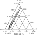
実施例1−粒子組成物
粒子組成物(モル分率)(0.52〜0.57)SiO2-0.035CaO-(0.00〜0.29)-ZnO-0.035MgO-(0.00〜0.188)La2O3-0.035SrO-(0.00〜0.05)TiO2-0.035Na2Oをこの実験のために合成した。分析等級試薬:二酸化ケイ素、炭酸カルシウム、酸化亜鉛、酸化マグネシウム、酸化ランタン(III)、炭酸ストロンチウム、二酸化チタンおよび炭酸ナトリウム(Sigma Aldrich、カナダ)を秤量し、プラスチック容器(Nalgene(商標)、Sigma Aldrich、カナダ)中で1時間均質に混合した。各バッチの粉末を白金るつぼ(50mL)中に入れ、次いでBench-Top High Temperature Muffle Furnace(EQ-KSL、MTI Corporation. USA)を用いて加熱(1480℃、1時間)し、水中で急冷した。得られたフリットを乾燥器内で乾燥し(120℃、1日)、めのう遊星ミル(Pulverisette 7;Laval Labs Inc.、カナダ)中で粉砕し、様々な孔径を通してふるいにかけて、以下のサイズ範囲の粉末微粒子を生成した:<45μm;45〜212μm;212〜300μm;355〜500μm;>500μm。この実験で生成したすべてのバッチの粒子を、この後さらなる評価のために乾燥デシケーター中で保存した。
Example 1 - particle composition particle composition (mole fraction) (0.52~0.57) SiO 2 -0.035CaO- ( 0.00~0.29) -ZnO-0.035MgO- (0.00~0.188) La 2 O 3 -0.035SrO- (0.00-0.05) TiO 2 -0.035Na 2 O was synthesized for this experiment. Analytical grade reagents: Weigh silicon dioxide, calcium carbonate, zinc oxide, magnesium oxide, lanthanum (III) oxide, strontium carbonate, titanium dioxide and sodium carbonate (Sigma Aldrich, Canada) and weigh plastic containers (Nalgene ™, Sigma Aldrich) , Canada) for 1 hour. Each batch of powder was placed in a platinum crucible (50 mL), then heated (1480 ° C., 1 hour) using a Bench-Top High Temperature Muffle Furnace (EQ-KSL, MTI Corporation. USA) and quenched in water. The resulting frit is dried in a dryer (120 ° C., 1 day), ground in an agate planetary mill (
粒状材料の特徴付け
示差走査熱量測定(DSC)
一般に、DSCを用いて各ガラスのガラス転移温度(Tg)の開始を、示差走査熱量計(DSC)を用いて判定する。258.15℃(最大725℃まで)の温度間隔を、空気中で、対応させた白金るつぼ中のアルミナ(または他の適切な参照)と共に用いる。用いたDSCの耐用性はおよそ2%である。
Characterization of granular materials
Differential scanning calorimetry (DSC)
Generally, the onset of the glass transition temperature (T g ) of each glass is determined using DSC using a differential scanning calorimeter (DSC). A temperature interval of 258.15 ° C. (up to 725 ° C.) is used in air with alumina in a corresponding platinum crucible (or other suitable reference). The durability of the DSC used is approximately 2%.
実施例2
実施例1で作成した粒子のDSC分析を実施して、ガラス転移温度(Tg)の値を得た。試料(約80mg)を窒素雰囲気下、白金るつぼ中で、空の参照るつぼと一緒に加熱した。標準参照材料は所与の温度範囲のためにすでに事前選択している。Tgを示差走査熱量計(DSC:TA Instruments-DQ200)で、25℃から725℃の間を、258.15℃の温度間隔で測定した。8つの粒子(ORP1〜3、ORP5〜7、ORP9およびORP11)のDSCトレースを図2に示す。表4は、Tg低下線形混合多項式モデルの要約したANOVA表である。L-Pseudo成分コーディングに関して作成した回帰モデルに基づき、各材料組成物のTg挙動の観察値と計算値との間の比較を表にして表5に示す。L-Pseudo成分に関する最終数学的モデルを以下のとおり式1で示す:
Tg(℃)=+634.82ZnO+833.28La2O3+677.19SiO2+699.01TiO2 式1。
Example 2
DSC analysis of the particles prepared in Example 1 was performed to obtain a glass transition temperature (T g ) value. A sample (approximately 80 mg) was heated with an empty reference crucible in a platinum crucible under a nitrogen atmosphere. Standard reference materials are already preselected for a given temperature range. T g was measured with a differential scanning calorimeter (DSC: TA Instruments-DQ200) between 25 ° C. and 725 ° C. at a temperature interval of 258.15 ° C. DSC traces of 8 particles (ORP1-3, ORP5-7, ORP9 and ORP11) are shown in FIG. Table 4 is a ANOVA table summarizing a T g decrease linear mixed polynomial model. Table 5 shows a comparison between the observed and calculated values of the T g behavior of each material composition based on the regression model created for L-Pseudo component coding. The final mathematical model for the L-Pseudo component is shown in
T g (° C.) = + 634.82ZnO + 833.28La 2 O 3 + 677.19SiO 2 + 699.01TiO 2 Formula 1.
(表4)
(表5)Tg試験の残差
X線回折(XRD)
一般に、XRDを用いてガラスのアモルファス特性を確認する。各ガラスの粉末試料を圧迫してディスク(Φ32mm×3mm)を形成する。回折パターンを、X線回折装置を用い、40KVおよび35mAの単色化CuKα(λ=1.54060A)照射により収集する。走査角範囲(2θ)を10°から70°まで、ステップサイズ0.033423°およびステップ時間59.69秒で実施する。
X-ray diffraction (XRD)
In general, XRD is used to confirm the amorphous properties of glass. Each glass powder sample is pressed to form a disk (Φ32 mm × 3 mm). Diffraction patterns are collected using an X-ray diffractometer with 40 KV and 35 mA monochromated CuKα (λ = 1.54060A) irradiation. The scan angle range (2θ) is performed from 10 ° to 70 ° with a step size of 0.033423 ° and a step time of 59.69 seconds.
実施例3
粒子のX線回折(XRD)測定を、X線発生装置(40kV;35mA)に接続し、Cu標的X線管を備えた、彎曲位置敏感検出器によるINEL CPS-120回折計を用いて実施した。試料を、選択した微量粒子(45〜212μm)を中空角形スチールウェーハ中に圧迫することにより調製した。入射ビーム経路における単色計は、試料をCu Kα1,α2に衝突させる波長を制限する。X線ビームは試料上に約6°で入射し、彎曲位置敏感検出器は走査角範囲10°<2θ<110°のすべての散乱したX線を収集する。XRDスペクトルの収集時間は1800秒である。粉末試料を、測定および移動操作を逐次プログラムすることを可能にする、INELのx-yトランスレーションステージ上に設置した。
Example 3
Particle X-ray diffraction (XRD) measurements were performed using an INEL CPS-120 diffractometer with a curved position sensitive detector connected to an X-ray generator (40 kV; 35 mA) and equipped with a Cu target X-ray tube . Samples were prepared by pressing selected microparticles (45-212 μm) into a hollow square steel wafer. The monochromator in the incident beam path limits the wavelength at which the sample collides with Cu Kα1, α2. The X-ray beam is incident on the sample at approximately 6 °, and the curved position sensitive detector collects all scattered X-rays with a scan angle range of 10 ° <2θ <110 °. The collection time for the XRD spectrum is 1800 seconds. The powder sample was placed on the INEL xy translation stage, which allows the measurement and transfer operations to be programmed sequentially.
図3は、合成した各材料のXRDパターンを示す(A)ガラスORP 2、3、5、7、9、11および(B)ORP 1および6。x軸は2θの角度で測定した散乱角を示し、y軸は任意の単位である。表6は、相識別のための記号を提供する。
FIG. 3 shows the XRD pattern of each synthesized material (A)
(表6)
驚くことに、これらの複合多成分系のTgは、4つの組成変種のいずれを増やしても上昇し、組成変種についてのその統計学的有意性レベルは以下の順となる:La2O3>TiO2>SiO2>ZnO。SiO2含有量を増やすだけでTgの上昇を引き起こすと期待されたかもしれない。興味深いことに、より弱いガラス網目の形成が原因とされるTgの低下に伴い、本明細書における一連のガラスで最も強い網目から最も弱い網目までが形成され、以下の順となる:ORP5>ORP3>ORP7>ORP2>ORP11>ORP9。 Surprisingly, the T g of these complex multicomponent systems increases with any increase in any of the four composition variants, and its statistical significance level for the composition variants is in the following order: La 2 O 3 > TiO 2 > SiO 2 > ZnO. Just increasing the SiO 2 content may have been expected to cause an increase in T g. Interestingly, with the decrease T g of the formation of weaker glass network it is caused until the weakest network from strongest mesh in a series of glass herein are formed, the following order: ORP5>ORP3>ORP7>ORP2>ORP11> ORP9.
網目連結度
実施例4
各組成物の網目連結度(NC)を、式2およびガラスのモル組成を用いて計算した1,2。結果を表1に示す。
Example 4
The network connectivity (NC) of each composition was calculated using
実験計画法(DoE)アプローチを用いての数学的モデルの作成と適用
二次標準シェッフェ多項式の係数を推定するために3,4、定義ドメイン(デザインスペース)内の異なる組成変種(デザインポイント)を表す13の実験による二次ユーザー定義計画を、Design-Expert 8.0.4ソフトウェア(Stat-Ease, Inc.)を用いて作成した。これらのデザインポイントは、各組成物の制約された範囲に基づいて決定し:6つの実験は頂点先端に設定し;さらなる6つはアキシャルチェックブレンドを調べ、1つは定義デザインスペース内の全体の重心であった。これらの点は、ドメインの興味が持たれる点はそのトップ、サイドの真ん中、フェースの真ん中、およびその重心である、シェッフェの提案と明らかに一致する(表1参照)。混合計画法により、等式を得る。この式はYを、4つの組成因子(ZnO、La2O3、SiO2およびTiO2、それぞれX1、X2、X3およびX4と示す)と連結する。
Create and apply mathematical models using the design of experiments (DoE) approach 3 , 4 , different composition variants (design points) in the definition domain (design space) to estimate the coefficients of second-order standard Scheffe polynomials A secondary user-defined plan with 13 experiments represented was created using Design-Expert 8.0.4 software (Stat-Ease, Inc.). These design points are determined based on the constrained extent of each composition: 6 experiments set at the apex; another 6 examines the axial check blend, and one is the overall design space within the definition design space. It was the center of gravity. These points are clearly consistent with Scheffe's proposal, where the domain's interest is at the top, the middle of the side, the middle of the face, and its center of gravity (see Table 1). The equation is obtained by the mixed programming method. This formula links Y with four composition factors (ZnO, La 2 O 3 , SiO 2 and TiO 2 , denoted as X 1 , X 2 , X 3 and X 4 respectively).
マジック角回転-核磁気共鳴(MAS-NMR)分光法およびDSC反応に適合させた通常の二次シェッフェ(線形)多項式(化学シフトおよび線幅)は下記である:
YA=β1X1+β2X2+β3X3+β4X4+e 式3
式中、X1〜X4は組成因子であり、β1〜4係数は個々の組成因子X1〜4の効果である。eは残差と呼び、この値は選択した各ガラスの計算値と実験値との間の差である。保持するガラスの数が式中の係数の数と同じである場合、これは0となる。選択したガラスの数が係数の数よりも多い場合、残差は各実験で異なる値を有する。
The usual second-order Scheffe (linear) polynomials (chemical shifts and line widths) adapted for magic angle rotation-nuclear magnetic resonance (MAS-NMR) spectroscopy and DSC reactions are:
Y A = β 1 X 1 + β 2 X 2 + β 3 X 3 + β 4 X 4 +
In the formula, X 1 to X 4 are composition factors, and β 1 to 4 coefficients are the effects of the individual composition factors X 1 to 4 . e is called the residual, which is the difference between the calculated and experimental values for each selected glass. If the number of glasses to hold is the same as the number of coefficients in the formula, this will be zero. If the number of selected glasses is greater than the number of coefficients, the residual has a different value in each experiment.
密度および細胞生存度反応に適合させた標準のシェッフェ二次多項式は下記である:
Y=β1X1+β2X2+β3X3+β4X4+β12X1X2+β13X1X3+β14X1X4+β23X2X3+β24X2X4+β123X1X2X3+β124X1X2X4+β134X1X3X4+β234X2X3X4+e 式4
式中、X1〜X4は組成因子であり、β1〜4係数は個々の組成因子X1〜4の効果であり;β12〜24は組成因子間の二方向相互作用の効果を表す回帰の係数であり;β123〜234は組成因子間の三方向相互作用の効果を表す回帰の係数であり、eは残差である。
A standard Scheffe quadratic polynomial adapted to density and cell viability responses is:
Y = β 1 X 1 + β 2 X 2 + β 3 X 3 + β 4 X 4 + β 12 X 1 X 2 + β 13 X 1 X 3 + β 14 X 1 X 4 + β 23 X 2 X 3 + β 24 X 2 X 4 + β 123 X 1 X 2 X 3 + β 124 X 1 X 2 X 4 + β 134 X 1 X 3 X 4 + β 234 X 2 X 3 X 4 + e Equation 4
Where X 1 to X 4 are composition factors, β 1 to 4 coefficients are the effects of individual composition factors X 1 to 4 ; β 12 to 24 represent the effects of bidirectional interactions between the composition factors Β 123-234 is a regression coefficient representing the effect of the three-way interaction between the composition factors, and e is the residual.
偽および実の値で示した二次モデルの推定係数から、各成分の効果を誘導することができる。反応変数を偽成分の比率に関連づけるすべての混合実験モデルを作成した。偽成分の比率(zi)を以下のとおりに計算する:
zi=(xi−Li)/(1−ΣL) 式5
式中、xiは元の成分比率を表し、Liはi番目の成分の下限(限界)を表し、Lはデザインにおけるすべての成分のすべての下限(限界)の合計を表し、1は混合物合計を表す。
The effect of each component can be derived from the estimated coefficients of the quadratic model indicated by false and real values. All mixed experimental models that relate reaction variables to the proportion of pseudocomponents were created. Calculate the false component ratio (z i ) as follows:
z i = (x i −L i ) / (1−ΣL)
Where x i represents the original component ratio, L i represents the lower limit (limit) of the i th component, L represents the sum of all lower limits (limits) of all components in the design, 1 is the mixture Represents the sum.
偽成分は元の(実の)成分の組み合わせであり、これは各偽成分の最小許容可能比率がゼロであるように、制約組成物領域を修正する。この変換により、実成分系を用いる場合に比べて、モデル係数がより正確に推定され、したがって以下の議論の文脈では偽成分スケーリングに基づいて誘導した係数を指す。しかし、実験対計算データ点およびグラフ表示(等高線プロット)に関して、モデルの有効性を実成分コーディングによって示す。 A pseudo component is a combination of the original (real) components, which modifies the constrained composition region so that the minimum acceptable ratio of each pseudo component is zero. With this transformation, model coefficients are estimated more accurately than when using a real component system, and thus refer to coefficients derived based on pseudo component scaling in the context of the following discussion. However, the effectiveness of the model is shown by real component coding with respect to experimental versus calculated data points and graphical representation (contour plot).
いくつかの反応特性y1、y2、...、ynがq成分の同じ組の比率でモデリングされている場合、組成物スペースにおいて最良の総括的特性組は望ましさ機能アプローチを実行することによって得られる。反応特性に基づくモデルを用いて、特定の目的のために望ましい特性を有する特定の材料のための組成物を決定することができる。 If several reaction characteristics y 1 , y 2 , ..., y n are modeled with the same set proportions of q components, the best overall characteristic set in the composition space implements the desirability functional approach Can be obtained. A model based on reaction characteristics can be used to determine a composition for a particular material that has desirable properties for a particular purpose.
真の密度
実施例5
真の密度を、本明細書において合成したすべての粒子についてと、市販の対照材料:Contour(商標)(PVA微粒子)についても、ヘリウム比重びん(AccuPyc 1340、Micromeritics)を用いて測定した。結果は5つの測定記録の平均の代表である。図4Aおよび4Bは得られた等高線プロットで、実成分コーディングにおける4つの様々なTi添加(0.017、0.033、0.042および0.05モル)での実験的粒子密度(g/cc)に対する組成-相互作用効果を示す。(A)はTi:0.017モル分率であり;(B)はTi:0.033モル分率であり;(C)はTi:0.042モル分率であり;かつ(D)はTi:0.050モル分率である。
True density Example 5
True density was measured using a helium specific gravity bottle (AccuPyc 1340, Micromeritics) for all the particles synthesized herein and also for the commercial control material: Contour ™ (PVA microparticles). Results are representative of the average of 5 measurement records. Figures 4A and 4B are the resulting contour plots showing the composition-interaction effect on experimental particle density (g / cc) at four different Ti additions (0.017, 0.033, 0.042 and 0.05 moles) in real component coding. Show. (A) is Ti: 0.017 mole fraction; (B) is Ti: 0.033 mole fraction; (C) is Ti: 0.042 mole fraction; and (D) is Ti: 0.050 mole fraction. It is.
表7は、L_Pseudo(1);実成分(2)に関する最終回帰式ならびにR2値;および密度についてのANOVAの概要を示す。ANOVAデータは、モデルが粒状材料の特徴を十分に予測することを示している。 Table 7 shows a summary of ANOVA for L_Pseudo (1); final regression equation and R 2 value for real component (2); and density. ANOVA data shows that the model fully predicts the characteristics of granular materials.
(表7)
表8は、有意な(正および負)主となる相互作用および二次組成因子(最高から最低まで順位付け)ならびに密度増大に対するその効果のまとめであり;↑は増大を示し、↓は低減を示す。実成分コーディングに基づく。 Table 8 summarizes significant (positive and negative) major interactions and secondary composition factors (ranked from highest to lowest) and their effect on density increase; ↑ indicates increase, ↓ indicates decrease Show. Based on real component coding.
(表8)
示したとおり、密度はLa2O3>ZnO>TiO2>SiO2の順で4つの組成変種のいずれを増やすことによっても増大しうる。興味深いことに、ZnOおよびLa2O3の相互作用(5番目の影響因子)を増やすと、予測されていなかったが、開示したモデルは開示した組成について予測している特徴の、材料密度の増大を引き起こしうる。試験した計画マトリックスにおいて達成された最低レベルの密度(3.2g/cc(ORP2)および3.3(ORP11))は、ORP2からORP11への組成変種におけるわずかな変動(ZnO含有量増加(0.05モル分率)およびTiO2含有量減少(0.5モル分率))が、得られる最終細胞生存度にいかに有害に作用しうるかを示しており;それぞれ84%から61%に低減する。興味深いことに、3.5g/cc(±0.3)の範囲の密度(ORP2、3および5)は、得られる細胞生存度(86%(±5)に関して、上位3つの組成変種の代表でもあった。 As shown, the density can be increased by increasing any of the four composition variants in the order La 2 O 3 >ZnO> TiO 2 > SiO 2 . Interestingly, increasing the interaction between ZnO and La 2 O 3 (5th influencing factor) was not expected, but the disclosed model increased the material density, a feature that is expected for the disclosed composition Can cause. The lowest level of density achieved in the tested design matrix (3.2 g / cc (ORP2) and 3.3 (ORP11)) is a slight variation (ZnO content increase (0.05 mole fraction)) in the composition variant from ORP2 to ORP11 And the TiO 2 content reduction (0.5 molar fraction) shows how it can adversely affect the final cell viability obtained; from 84% to 61%, respectively. Interestingly, densities in the range of 3.5 g / cc (± 0.3) (ORP2, 3 and 5) were also representative of the top three compositional variants with respect to the resulting cell viability (86% (± 5)).
比表面積決定
N2吸収/脱着を、Brunauer-Emmett-Teller(BET)法を用いて調べ、調製したガラス粉末の比表面積(SSA)および多孔度を求める。ガラス試料(約0.15g±0.05g)を窒素雰囲気下、77.35Kに、平衡間隔10秒で置く。
Specific surface area determination
N 2 absorption / desorption is examined using the Brunauer-Emmett-Teller (BET) method to determine the specific surface area (SSA) and porosity of the prepared glass powder. A glass sample (approximately 0.15 g ± 0.05 g) is placed at 77.35 K in a nitrogen atmosphere with an equilibration interval of 10 seconds.
実施例6
微量微粒子およびContour(商標)の理論外部比表面積を、球状微粒子形態の仮定のもと、以下の式5によって計算した
The theoretical external specific surface area of microparticles and Contour (TM) was calculated by Equation 5 below under the assumption of spherical microparticle morphology
表9は、比表面積測定値を提供する(45ミクロン(より低いレベル、LL)および212ミクロン(より高いレベル、UL)。 Table 9 provides specific surface area measurements (45 microns (lower level, LL) and 212 microns (higher level, UL).
(表9)
走査電子顕微鏡法
実施例7
走査電子顕微鏡(SEM)観察のために、粉末試料(粒径範囲:355〜500μm)を直径10mm×高さ3mmのAlスタブに固定し、約27nmの白金で金スパッターコーター(SC7640、Fisons Instruments)を用いてコーティングした。続いて、形態学的および化学的分析のために、試料を、Oxford Incaエネルギー分散性x線分光法(EDS)装置を備えたHitachi S-4700 FEG-SEMのチャンバーに移した。下方二次電子(SE)検出器で、加速電圧5.0kVおよび作動距離11〜12mmを用いた。
Scanning electron microscopy
Example 7
For scanning electron microscope (SEM) observation, a powder sample (particle size range: 355 to 500 μm) was fixed to an Al stub with a diameter of 10 mm and a height of 3 mm, and a gold sputter coater (SC7640, Fisons Instruments) with approximately 27 nm of platinum. Was used to coat. Subsequently, samples were transferred to a Hitachi S-4700 FEG-SEM chamber equipped with an Oxford Inca energy dispersive x-ray spectroscopy (EDS) apparatus for morphological and chemical analysis. A lower secondary electron (SE) detector was used with an acceleration voltage of 5.0 kV and a working distance of 11-12 mm.
図5は、1つの実験組成物(ORP5)から誘導した形態学的データ(SEM)を示し;その形態は試験した多成分系のすべての組の代表であり、市販の合法的に市販された装置(predicate device)、Contourと比較している。図5Aは、粒径範囲355〜510μmのContour(商標)の対照試料である。図5Bは、粒径範囲355〜510μmを有するORP5の実験試料である。 FIG. 5 shows morphological data (SEM) derived from one experimental composition (ORP5); the form is representative of all sets of multicomponent systems tested and commercially available legally Compared with predicate device, Contour. FIG. 5A is a Contour ™ control sample with a particle size range of 355-510 μm. FIG. 5B is an experimental sample of ORP5 having a particle size range of 355-510 μm.
ORP5の化学的(EDX)データを図6に示し、合成した組成物が表1に報告するとおりであることを示している。 The chemical (EDX) data for ORP5 is shown in FIG. 6, indicating that the synthesized composition is as reported in Table 1.
非架橋酸素の判定のためのマジック角回転-核磁気共鳴(MAS-NMR)分光法
一般に、ガラスの29Si MAS-NMRスペクトルを、ケイ素に対する1.5μsの高電力パルス(P1)取得を用い、回転周波数5kHzで記録する。29Si MAS-NMR試料を、リサイクル/遅延時間(recycle/delay time)を約2秒に設定して回転させる。29Si NMR化学シフトをppmで報告し、周囲のプローブ温度で、2,2-ジメチル-2シラペンタン-5-スルホン酸ナトリウム(DSS)または他の適切な参照品に対して外部参照した29Siにより記録する。固体状態のNMRについて、MASを用いて記録したシフトは試料の等方性バルク磁化率とは無関係である。理想的材料では、データの化学シフトの推定誤差は約0.1ppmで;この値を超える小さい変動が観察されることもある。
Magic Angle Rotation-Nuclear Magnetic Resonance (MAS-NMR) Spectroscopy for Determination of Non-Bridged Oxygen Generally, 29 Si MAS-NMR spectra of glass are rotated using a 1.5 μs high power pulse (P1) acquisition for silicon Record at a frequency of 5 kHz. Rotate the 29 Si MAS-NMR sample with a recycle / delay time of about 2 seconds. 29 Si NMR chemical shifts reported in ppm and at ambient probe temperature by 2, Si-2,2-dimethyl-2silapentane-5-sodium sulfonate (DSS) or externally referenced 29 Si Record. For solid state NMR, the shift recorded using MAS is independent of the isotropic bulk susceptibility of the sample. For an ideal material, the estimated error in the chemical shift of the data is about 0.1 ppm; small variations beyond this value may be observed.
実施例8
29Siマジック角回転(MAS)NMR試験を、9.4T磁石のBruker Avance NMR分光計(79.51MHz 29Si ラーモア回転数)で、回転子直径7mmのプローブヘッドを用いて実施した。標品(<45μm)を5.00kHzで回転させた。rf磁場強度28kHzで、80°のパルス長を用い、シングルパルス励起で200スキャンを蓄積した。待ち時間を、インバージョンリカバリシーケンスにより求めたスピン格子緩和時間の3倍となるよう選択した。スピン格子緩和時間は15秒から26秒の範囲である。化学シフトスケールを、-91.34ppmの二次化学シフト標準としてカオリンに対して外部参照した。ピーク最大点およびピーク幅上の誤差バーは±1ppmである。
Example 8
A 29 Si magic angle rotation (MAS) NMR test was performed on a Bruker Avance NMR spectrometer (79.51 MHz 29 Si Larmor number of revolutions) with a 9.4 T magnet using a probe head with a rotor diameter of 7 mm. A sample (<45 μm) was rotated at 5.00 kHz. 200 scans were accumulated with single pulse excitation using an rf magnetic field strength of 28 kHz and a pulse length of 80 °. The waiting time was chosen to be 3 times the spin lattice relaxation time determined by the inversion recovery sequence. The spin lattice relaxation time ranges from 15 to 26 seconds. The chemical shift scale was externally referenced to kaolin as a secondary chemical shift standard of -91.34 ppm. Error bars on the peak maximum and peak width are ± 1 ppm.
図7は、線幅の低減により分類した(a:ORP11、b:ORP2、c:ORP9、d:ORP7、e:ORP6、f:ORP5、g:ORP3、h:ORP1)、各実験的塞栓材料の29Si MAS-NMRスペクトルを示す(それぞれのピーク最大点およびピーク幅をそれぞれ表10に示す)。速すぎるパルシング(50秒)により結晶シグナルを落としていないことを確認するために、ORP6のさらなる29Si MAS NMRスペクトルを、より長い反復時間(90秒)で取得した。図8は、反復時間(a)90秒および(b)50秒での実験的塞栓材料ORP6の29Si MAS-NMRスペクトル、ならびに(c)それらの調整した差を示し;シリカがXRDによって検出された結晶の一部ではないことを検証している。両方のスペクトルにおいて、結晶性成分は認められなかった。ORP1およびORP6のXRDディフラクトグラムは、表6において識別したいくつかの結晶種の存在を示している。 Figure 7 shows the classification of each experimental embolic material (a: ORP11, b: ORP2, c: ORP9, d: ORP7, e: ORP6, f: ORP5, g: ORP3, h: ORP1). 29 Si MAS-NMR spectrum is shown (each peak maximum point and peak width are shown in Table 10). To confirm that the crystal signal was not dropped by too fast pulsing (50 seconds), an additional 29 Si MAS NMR spectrum of ORP6 was acquired with a longer repetition time (90 seconds). Figure 8 shows the 29 Si MAS-NMR spectra of the experimental embolic material ORP6 at repetition times (a) 90 seconds and (b) 50 seconds, and (c) their adjusted difference; silica was detected by XRD It is verified that it is not part of the crystal. No crystalline component was observed in both spectra. The XRD diffractogram of ORP1 and ORP6 shows the presence of several crystal species identified in Table 6.
図9は、実成分コーディングにおける4つの様々なTi添加((図9A)0.017、(図9B)0.033、(図9C)0.042および(図9D)0.05モル)での実験的塞栓材料29Si MAS-NMR化学シフト(ppm)に対する組成-相互作用効果を示す、等高線プロットを示す。 Figure 9 shows the experimental embolic material 29 Si MAS- with four different Ti additions in real component coding ((Figure 9A) 0.017, (Figure 9B) 0.033, (Figure 9C) 0.042 and (Figure 9D) 0.05 mol) Figure 2 shows a contour plot showing the composition-interaction effect on NMR chemical shift (ppm).
図10は、実成分コーディングにおける4つの様々なTi添加((図10A)0.017、(図10B)0.033、(図10C)0.042および(図10D)0.05モル)での実験的塞栓材料29Si MAS-NMRスペクトル線幅(ppm)に対する組成-相互作用効果を示す、等高線プロットを示す。 Figure 10 shows the experimental embolic material 29 Si MAS- with four different Ti additions ((Figure 10A) 0.017, (Figure 10B) 0.033, (Figure 10C) 0.042 and (Figure 10D) 0.05 moles) in real component coding Figure 2 shows a contour plot showing the composition-interaction effect on NMR spectral linewidth (ppm).
表10は、表1(ここで、SiO2、TiO2、ZnOおよびLa2O3は変動し、CaO、Na2O MgOおよびSrOは等モル濃度)に概要を示す組成式からの正電荷の総数ならびに関連するNMR最大点の位置および線幅を示す。 Table 10 Table 1 (wherein, SiO 2, TiO 2, ZnO and La 2 O 3 is varied, CaO, Na 2 O MgO and SrO equimolar concentration) of the positive charge from the composition formula outlined in The total number and the position and line width of the associated NMR maximum point are indicated.
(表10)
表11は、L_Pseudo(1);実成分(2)に関する回帰式ならびにR2値;および各反応についてのANOVAの概要を示す。ANOVAデータは、モデルが反応AおよびBに対する粒状材料の特徴を十分に予測することを示している。 Table 11 shows L_Pseudo (1); regression equation for real component (2) and R 2 value; and ANOVA summary for each reaction. The ANOVA data shows that the model fully predicts the characteristics of the particulate material for reactions A and B.
(表11)
表12は、有意な(正および負)主となる相互作用および二次組成因子(最高から最低まで順位付け)ならびに負の方向への化学シフト/ピーク位置生成および線幅増大に対するその効果のまとめを示し;↑は増大を示し、↓は低減を示す。データは実成分コーディングに基づく。 Table 12 summarizes significant (positive and negative) main interactions and secondary composition factors (ranked from highest to lowest) and their effect on chemical shift / peak position generation and linewidth increase in the negative direction. ↑ indicates an increase and ↓ indicates a decrease. Data is based on real component coding.
(表12)
表13は、合成したすべての材料組成物についての29Si MAS-NMR化学シフト(a)および線幅(b)の残差を示す。 Table 13 shows the 29 Si MAS-NMR chemical shift (a) and linewidth (b) residuals for all synthesized material compositions.
(表13)
NMRスペクトルに示すとおり、両方のNMRピークシフトはSiO2>TiO2>ZnO>La2O3の順で4つの組成変種のいずれを減らすことによっても増大し得、線幅はLa2O3を除いて同じ順に従う。ORP2、9および11について得たNMRスペクトル(図7)は、すべての他の組成物について得た他のスペクトルよりも有意に広いようである。対応する標品の間の差は、ORP2、9および11はランタンを含まないが、他は含むことである。
As shown in the NMR spectrum, both NMR peak shifts can be increased by reducing any of the four compositional variants in the order of SiO 2 > TiO 2 >ZnO> La 2 O 3 and the line width can be reduced to La 2 O 3 . Follow the same order except. The NMR spectra obtained for ORP2, 9, and 11 (Figure 7) appear to be significantly broader than the other spectra obtained for all other compositions. The difference between the corresponding preparations is that
標品ORP2は、ORP11に比べて、ZnOを犠牲にしてより多くのTiO2からなり、したがってより高い電荷対シリカ比を有するが、Qn(nSi, 4-nTi)種はQn(nSi, 4-nZn)種よりも低いppm値で共鳴する。電荷対シリカ比に基づき、かつ大まかに二元Q種分布を仮定して、ORP11および2はQ3/Q2範囲で共鳴すべきであり、かつ実験的に共鳴し、標品ORP9、7、5、3、および1はQ2/Q1範囲で(逆重畳積分はQ1部位の存在を示し)、かつ標品ORP6および以下はQ1/Q0範囲で共鳴するが、標品ORP10はQ0および別の金属酸化物種だけからなるべきである。興味深いことに、標品ORP1および6について、(すなわち、電荷対シリカ比がQ0寄与の範囲に入る場合)、ガラス状および結晶成分への分離はより高い電荷比ですでに起こっており、フリットにすることはまったくできない。標品ORP6におけるこの相分離は、なぜそのNMR特性がORP7およびORP5のスペクトルのものの間に入るかの理由であり、これはカチオン-酸化物吸引性の結晶、およびNMRによって試験する異なる組成物のガラスにおける結果による。La2O3は、あまり高くない濃度でも、ガラスの分解を引き起こす。これは、粒状材料の分解の調整可能性の一助となるため、有用である。
The standard ORP2 consists of more TiO 2 at the expense of ZnO and therefore has a higher charge-to-silica ratio compared to ORP11, but the Q n (nSi, 4-nTi) species is Q n (nSi, Resonates at a lower ppm value than the 4-nZn) species. Based on the charge-to-silica ratio and roughly assuming a binary Q species distribution,
ガラスおよび複合材料からの分解生成物の定量
それぞれpH7.4±0.1およびpH3.0±0.2のトリス-HCl緩衝液およびクエン酸緩衝溶液を調製して、正常および極度の生理的条件(ISO10993-14による)を模擬する。いずれの緩衝溶液もガラスからの分解生成物の定量のために用いる。各粒状材料100mgを、振盪水浴中で37℃に維持したポリプロピレンチューブ中、各溶液(n=3)10mlに浸漬し、2Hzで撹拌する。標品を様々な期間−例えば、1、3、7、または30日間保存する。各期間の後、標品を取り出し、等級5のWhatmanろ紙を通してろ過し、ろ液をイオン含有量分析のために保持する。がラスからの分解生成物を同定し、誘導結合プラズマ−質量分析計を用いて定量する。各抽出物の分析を三つ組で実施する(n=3(条件ごとの抽出物)、各抽出物に対して3回の分析を実施)。
Quantification of degradation products from glass and composite materials Tris-HCl buffer and citrate buffer solutions at pH 7.4 ± 0.1 and pH 3.0 ± 0.2, respectively, were prepared for normal and extreme physiological conditions (ISO10993-14 )). Either buffer solution is used for quantification of degradation products from the glass. 100 mg of each granular material is immersed in 10 ml of each solution (n = 3) in a polypropylene tube maintained at 37 ° C. in a shaking water bath and stirred at 2 Hz. The preparation is stored for various periods of time-for example, 1, 3, 7, or 30 days. After each period, the preparation is removed and filtered through
イオン放出特性の分析
塞栓剤からのイオン放出特性を、インキュベーション時間(X)に対するイオン放出濃度(Y)に関して記載する。インキュベーション時間は相間関数の入力ではないため、時間依存性関数を非線形回帰多項、ガウス、正弦波および指数モデルに、Prism 5.0ソフトウェア(GraphPad software Inc.)を用いてあてはめた。各塞栓剤に関する4つの要素の最適モデルは1フェーズ減衰結合モデルである:
Y=Y0+(プラトー−Y0)*(1−exp(-K*X)) 式7
式中:
「Y」および「X」はそれぞれイオン放出濃度(ppm)およびインキュベーション時間(時間)であり;
「Y0」は初期イオン放出時のイオン放出濃度(ppm)であり;ここでY値はX0=1における値であり;
「プラトー」は無限時間におけるイオン放出濃度(ppm)であり、ここでY値はX=120時間における値であり;
「K」は「tau」インキュベーション時間の逆数で表した速度定数であり、単位は日の逆数であり;
「tau」はイオン放出が推定「ymax」(ppm)の63%に達するのに必要な時間を意味し;
「t1/2」は最終「ymax」値の50%に達するための半減期(時間)を意味し、「t1/2=tau *LN(2)」:
「ts」はY0とプラトーとの間の差を意味し;
「R2」は、Prism 5.0(GraphPad Inc.)ソフトウェアで求めた、指数非線形回帰の最適からの点の距離の二乗の合計である。R2の値は0.0から1.0の間の有理数であり、最適線はR2=1.0のものである。
Analysis of ion release characteristics The ion release characteristics from the embolic agent are described in terms of ion release concentration (Y) versus incubation time (X). Since incubation time is not an input for interphase functions, time dependent functions were fitted to nonlinear regression polynomials, Gaussian, sinusoidal and exponential models using Prism 5.0 software (GraphPad software Inc.). The four-factor optimal model for each embolic agent is a one-phase attenuated coupling model:
Y = Y 0 + (plateau−Y 0 ) * (1−exp (−K * X))
In the formula:
“Y” and “X” are ion release concentration (ppm) and incubation time (hours), respectively;
“Y 0 ” is the ion emission concentration (ppm) at the initial ion release; where the Y value is the value at X 0 = 1;
“Plateau” is the ion emission concentration (ppm) at infinite time, where Y value is the value at X = 120 hours;
“K” is the rate constant expressed as the reciprocal of the “t au ” incubation time, the unit being the reciprocal of the day;
“T au ” means the time required for ion release to reach 63% of the estimated “y max ” (ppm);
“T 1/2 ” means half-life (time) to reach 50% of the final “y max ” value, “t 1/2 = t au * LN (2)”:
“T s ” means the difference between Y 0 and the plateau;
“R 2 ” is the sum of the squares of the distances of points from the optimal of exponential nonlinear regression, as determined by Prism 5.0 (GraphPad Inc.) software. The value of R 2 is a rational number between 0.0 and 1.0, and the optimal line is that of R 2 = 1.0.
マウス線維芽細胞株L929による細胞培養試験
樹立マウス線維芽細胞株L929(American Type Culture Collection CCL 1線維芽細胞、NCTCクローン929)を、10%ウシ胎仔血清および1%(2mM)L-グルタミンを補足したM199培地中で培養する。細胞を、5%CO2インキュベーター内、37℃の、T-75フラスコ中で成長させる。細胞がコンフルエンシーに達すれば、これらを0.25%トリプシンを用いて化学的に取り出し、遠心分離し、新鮮培地に再懸濁して、さらなる接種のための新しい単細胞懸濁液を作成する。
Cell culture test with mouse fibroblast cell line L929 Established mouse fibroblast cell line L929 (American Type
細胞生存度検定
3T3細胞を24穴プレート(Sarstedt、アイルランド)中1×10⁴/mlの密度で播種する。M199培地を陰性対照として用い、培地プラス細胞を陽性対照として用いる。次いで、プレートを37℃の細胞培養インキュベーター(5%CO2/95%空気雰囲気)内で24時間インキュベートする。24時間後、滅菌組織培養水100μlを対照ウェルに加える。関連する実験抽出物(粒子を含む)100μlを試験のために適切なウェルに加える。次いで、プレートを37℃の細胞培養インキュベーター(5%CO2/95%空気雰囲気)内で24時間インキュベートする。24時間のインキュベーション後、各ウェルを培地量の10%に等しい量(100μl)のMTT(Sigma Aldrich、アイルランド)に曝露する。プレートをインキュベーターに3時間戻す。インキュベーション後、MTT可溶化溶液を各ウェルに元の培地量と等しい量(1ml)で加える。結晶の溶解を増強するために、各ウェルをピペットを用いて滴定し、その後、各ウェルの吸光度を570nmの波長で分光測光法により測定する。細胞陽性対照ウェルは100%の代謝活性を有すると仮定し、実験抽出物に曝露した細胞の代謝活性パーセンテージをこれに対して計算した。
Cell viability test
3T3 cells are seeded at a density of 1 × 10 4 / ml in 24-well plates (Sarstedt, Ireland). M199 medium is used as a negative control and medium plus cells are used as a positive control. The plates are then incubated for 24 hours in a 37 ° C. cell culture incubator (5% CO 2 /95% air atmosphere). After 24 hours, 100 μl of sterile tissue culture water is added to control wells. Add 100 μl of the relevant experimental extract (containing particles) to the appropriate well for testing. The plates are then incubated for 24 hours in a 37 ° C. cell culture incubator (5% CO 2 /95% air atmosphere). After 24 hours of incubation, each well is exposed to an amount (100 μl) of MTT (Sigma Aldrich, Ireland) equal to 10% of the medium volume. Return plate to incubator for 3 hours. After incubation, MTT solubilization solution is added to each well in an amount equal to the original medium volume (1 ml). To enhance crystal dissolution, each well is titrated with a pipette, and then the absorbance of each well is measured spectrophotometrically at a wavelength of 570 nm. The cell positive control well was assumed to have 100% metabolic activity and the metabolic activity percentage of cells exposed to the experimental extract was calculated against this.
実施例9
分解試験のための粒子抽出物の調製
粒子およびContour(商標)(市販の対照)(Lot No.:13473927および13599201)0.1gを、2Hzで回転振動させた振盪水浴(Stuart Sb40、Techne Inc.、USA)中、37℃で、滅菌組織培養水(Sigma-Aldrich、カナダ)10ml6に12、24、48、96および120時間浸漬した。それぞれの保存期間の後、試料を滅菌0.20μmフィルター(Sarstedt、カナダ)を用いてろ過し、ろ液をインビトロ評価まで7℃で保存した。
Example 9
Preparation of particle extract for degradation test Particles and Contour ™ (commercial control) (Lot No .: 13473927 and 13599201) 0.1 g of a shaking water bath (Stuart Sb40, Techne Inc., during USA), at 37 ° C., sterile tissue culture water (Sigma-Aldrich, Canada) were immersed in
各抽出物についてSi4+、Na+、Ca2+、Zn2+、Ti4+、La3+、Sr2+、およびMg2+濃度を、誘導結合プラズマ原子発光分析(ICP-AES、Perkin Elmer Optima 3000、MA、USA)を用いて分析した。各元素の定量に用いた吸収波長を表14に報告する。各測定サイクルの前に、Ti4+、La3+、Sr2+、およびMg2+を含む標準溶液およびSi4+、Na+、Ca2+およびZn2+を含む別の標準溶液の組(JVA Analytical Ltd、アイルランドから入手)を、表15および16に報告する濃度で調製することにより較正曲線を得た。標準試料濃度を定期的に測定して、較正曲線の精度を確保した。各抽出物(インキュベートした各塞栓剤から)の三つ組を各元素について測定し、元の抽出物の希釈度を釣り合わせるために出力における適切な調節を行った。結果は、複合多成分系は分解性の速度調節を提供することを示している。 Si 4+ , Na + , Ca 2+ , Zn 2+ , Ti 4+ , La 3+ , Sr 2+ , and Mg 2+ concentrations for each extract were determined by inductively coupled plasma atomic emission spectrometry (ICP-AES, Perkin Elmer Optima 3000, MA, USA). The absorption wavelengths used for the quantification of each element are reported in Table 14. Before each measurement cycle, a set of standard solutions containing Ti 4+ , La 3+ , Sr 2+ , and Mg 2+ and another standard solution containing Si 4+ , Na + , Ca 2+ and Zn 2+ Calibration curves were obtained by preparing (obtained from JVA Analytical Ltd, Ireland) at the concentrations reported in Tables 15 and 16. Standard sample concentrations were measured periodically to ensure the accuracy of the calibration curve. Triplicates of each extract (from each incubated embolic agent) were measured for each element and appropriate adjustments in output were made to balance the dilution of the original extract. The results show that the complex multicomponent system provides degradable rate regulation.
(表14)
表15は、ICP測定(JVA Analytical、アイルランド)のために用いた標準濃度を示す。 Table 15 shows the standard concentrations used for ICP measurements (JVA Analytical, Ireland).
(表15)
表16は、ICP測定のために用いた実験室標準濃度を示す。 Table 16 shows the laboratory standard concentrations used for ICP measurements.
(表16)
図11は、8つの塞栓微粒子のSi(図11A)およびNa(図11B)放出のイオン放出特性を、12、24、48、96および120時間にわたる時間依存性と共に示す。線は視覚ガイドとして引いている。図12は、8つの塞栓微粒子のCa(図12A)およびSr(図12B)放出のイオン放出特性を、12、24、48、96および120時間にわたる時間依存性と共に示す。線は視覚ガイドとして引いている。図13は、8つの塞栓微粒子のTi(図13A)およびLa(図13B)放出のイオン放出特性を、12、24、48、96および120時間にわたる時間依存性と共に示す。線は視覚ガイドとして引いている。線は視覚ガイドとして引いている(R2<0.6のあいまいなデータは除外)。図14は、8つの塞栓微粒子のMgのイオン放出特性(図14A)およびZnの平均(±SD)放出レベル(図14B)を、12、24、48、96および120時間にわたる時間依存性と共に(Zn(図14B)についてのみ)示す。線は視覚ガイドとして引いている。線は視覚ガイドとして引いている(R2<0.6のあいまいなデータは除外)。図15は、120時間のインキュベーション期間後のSi(図15A)およびNa(図15B)の放出レベルに対する塞栓材料組成の効果を示す。図16は、120時間のインキュベーション期間後のCa(図16A)およびSr(図16B)の放出レベルに対する塞栓材料組成の効果を示す。図17は、120時間のインキュベーション期間後のTi(図17A);La(図17B)およびMg(図17C)の放出レベルに対する塞栓材料組成の効果を示す。 FIG. 11 shows the ion release characteristics of the Si (FIG. 11A) and Na (FIG. 11B) release of the eight embolic particles, with time dependence over 12, 24, 48, 96 and 120 hours. The line is drawn as a visual guide. FIG. 12 shows the ion release characteristics of the Ca (FIG. 12A) and Sr (FIG. 12B) release of the eight embolized microparticles with time dependence over 12, 24, 48, 96 and 120 hours. The line is drawn as a visual guide. FIG. 13 shows the ion release characteristics of Ti (FIG. 13A) and La (FIG. 13B) release of eight embolic particles, with time dependence over 12, 24, 48, 96 and 120 hours. The line is drawn as a visual guide. The line is drawn as a visual guide (excludes ambiguous data with R 2 <0.6). FIG. 14 shows the Mg ion release characteristics (FIG. 14A) and Zn mean (± SD) release levels (FIG. 14B) with time dependence over 12, 24, 48, 96 and 120 hours (FIG. 14A). Zn (only for FIG. 14B). The line is drawn as a visual guide. The line is drawn as a visual guide (excludes ambiguous data with R 2 <0.6). FIG. 15 shows the effect of embolic material composition on the release levels of Si (FIG. 15A) and Na (FIG. 15B) after a 120 hour incubation period. FIG. 16 shows the effect of embolic material composition on Ca (FIG. 16A) and Sr (FIG. 16B) release levels after a 120 hour incubation period. FIG. 17 shows the effect of embolic material composition on the release levels of Ti (FIG. 17A); La (FIG. 17B) and Mg (FIG. 17C) after a 120 hour incubation period.
表16は、5つの時点(12、24、48、96、120時間)でSi4+およびNa+放出から生成した非線形1フェーズ結合モデルに対する適合度(R2値に関して)を示す。 Table 16 shows the goodness of fit (relative to R 2 values) for a nonlinear one-phase coupled model generated from Si 4+ and Na + release at five time points (12, 24, 48, 96, 120 hours).
(表16)
表17は、5つの時点(12、24、48、96、120時間)でCa2+放出から生成した非線形1フェーズ結合モデルに対する最適パラメーターを示す。 Table 17 shows the optimal parameters for a non-linear one-phase binding model generated from Ca 2+ release at five time points (12, 24, 48, 96, 120 hours).
(表17)
表18は、5つの時点(12、24、48、96、120時間)でSr2+放出から生成した非線形1フェーズ結合モデルに対する最適パラメーターを示す。 Table 18 shows the optimal parameters for a non-linear one-phase binding model generated from Sr 2+ release at five time points (12, 24, 48, 96, 120 hours).
(表18)
表19は、5つの時点(12、24、48、96、120時間)でTi4+放出から生成した非線形1フェーズ結合モデルに対する最適パラメーターを示す。アステリスク(*)はあいまいとされたモデルを表す。 Table 19 shows the optimal parameters for the nonlinear one-phase binding model generated from Ti 4+ release at five time points (12, 24, 48, 96, 120 hours). An asterisk ( * ) represents an ambiguous model.
(表19)
表20は、5つの時点(12、24、48、96、120時間)でMg2+放出から生成した非線形1フェーズ結合モデルに対する最適パラメーターを示す。アステリスク(*)はあいまいとされたモデルを表す。 Table 20 shows the optimal parameters for a non-linear one-phase binding model generated from Mg 2+ release at five time points (12, 24, 48, 96, 120 hours). An asterisk ( * ) represents an ambiguous model.
(表20)
驚くことに、Zn2+は120時間後に初めて放出されることが見られただけであった。すべての他のイオンはすべての期間で持続的に放出されることが判明した。これは、Zn2+が溶液へのその浸漬の即時開始と共にイオンを放出するであろうとの予想に反するものである。 Surprisingly, Zn 2+ was only seen to be released for the first time after 120 hours. All other ions were found to be released continuously over all periods. This is contrary to the expectation that Zn 2+ will release ions with an immediate onset of its immersion in the solution.
Si4+およびNa2+両方のイオン放出特性は、120時間までのイオン放出における安定な時間依存的増大(Si4+についてはそれぞれ0.72および0.78のR2値を示すORP3および9を除く0.81から0.87の範囲のR2値、ならびにNa2+についてはそれぞれ0.63、0.54および0.67のR2値を示すORP6、9および11を除く0.71から0.90の範囲のR2値によって表される最適値によって示す)を示し、これは、各成分の制御可能な性質を示している可能性がある。イオン放出の完全な安定化は、120時間後にも両方のイオンについて明らかではない。 The ion release characteristics of both Si 4+ and Na 2+ are stable time-dependent increases in ion release up to 120 hours (from 0.81 except for ORP3 and 9, which show R 2 values of 0.72 and 0.78 for Si 4+ , respectively) shown by the optimum value represented by R 2 values ranging 0.87, and Na 2+ 0.71 from R 2 value in the range of 0.90 except ORP6,9 and 11 show an R 2 value of each 0.63,0.54 and 0.67 for ), Which may indicate the controllable nature of each component. Full stabilization of ion release is not evident for both ions after 120 hours.
ORP9について溶液中での最初の2〜3時間に放出されたCa2+の初期バーストが認められ、急激に終わって、試験の残りは安定な放出レベルを維持した。ORP1もCa2+放出の初期バーストを示し、24時間を超えて安定な速度でCa2+を徐々に放出した。しかし、残りの組成物は24時間までより漸進的な初期Ca2+放出を示し、その後完全な安定化に達した。これは、インキュベーション媒質中のH3O+と引き替えに、初期Ca2+放出(微粒子からの)の結果としてガラス微粒子の全表面領域にヒドロゲル様の層が形成され、微粒子の全表面上に沈澱し;さらに微粒子からのイオン放出の速度に影響をおよぼしたことによる可能性がある。興味深いことに、同じ放出特性がSr2+およびTi4+でも観察された。 An initial burst of Ca 2+ released in the first 2-3 hours in solution for ORP9 was observed, abruptly over and the rest of the test maintained a stable release level. ORP1 also showed an initial burst of Ca 2+ release and gradually released Ca 2+ at a stable rate over 24 hours. However, the remaining composition showed more gradual initial Ca 2+ release until 24 hours, after which full stabilization was reached. This, in exchange for H 3 O + in the incubation medium, forms a hydrogel-like layer on the entire surface area of the glass microparticles as a result of the initial Ca 2+ release (from the microparticles) and precipitates on the entire surface of the microparticles It may also be due to the effect on the rate of ion release from the microparticles. Interestingly, the same release characteristics were observed with Sr 2+ and Ti 4+ .
重要なことに、Mg2+の溶液中への非常に遅い放出レベルが認められ、これはケイ酸塩網目によって強力にキレート化されていることを示唆している。同じことが、ORP1を除くLa2+について報告されている(おそらくは結晶種における増大による)。 Importantly, a very slow release level of Mg 2+ into the solution is observed, suggesting that it is strongly chelated by the silicate network. The same has been reported for La 2+ except ORP1 (possibly due to an increase in crystalline species).
MTT/LDHの放出検定のための粒子抽出物の調製
このプロトコルのために、すべての粒子をインキュベーション前に121°/25barで、20分間の高圧滅菌(AMSCO Medallist)によって滅菌した。Contour(商標)の事前滅菌バッチ(Lot No.:13473927および13599201)を対照として用いた。続いて、等量(0.1g)の各滅菌ガラス(ORP1-3、ORP5-7、ORP9、ORP11)およびContour(商標)を10mLの滅菌組織培養水(Sigma-Aldrich、カナダ)に24時間浸漬し、37℃のインキュベーター内部に設置したローラー(約2Hzで回転)上に置いた。各保存期間の後、試料を滅菌0.20μmフィルター(Sarstedt、カナダ)を用いてろ過し、ろ液をインビトロ評価まで7℃で保存した。
Preparation of Particle Extract for MTT / LDH Release Assay For this protocol, all particles were sterilized by autoclaving (AMSCO Medallist) for 20 minutes at 121 ° / 25 bar prior to incubation. Contour ™ pre-sterilized batches (Lot No .: 13473927 and 13599201) were used as controls. Subsequently, an equal volume (0.1 g) of each sterilized glass (ORP1-3, ORP5-7, ORP9, ORP11) and Contour ™ was immersed in 10 mL of sterile tissue culture water (Sigma-Aldrich, Canada) for 24 hours. And placed on a roller (rotating at about 2 Hz) installed in an incubator at 37 ° C. After each storage period, the sample was filtered using a sterile 0.20 μm filter (Sarstedt, Canada) and the filtrate was stored at 7 ° C. until in vitro evaluation.
線維芽細胞培養
15〜20継代の不死化ラット線維芽細胞(NIH-3T3;American Type Tissue Collection、Manassas、VA)を、実験のために用いた。細胞を75-cm2組織培養フラスコ内の5%ウシ胎仔血清(FCS;56℃で60分間熱不活化)を補足したダルベッコ改変イーグル培地(DMEM)中で成長させた。細胞を剥離するために2mLの0.25%トリプシン-EDTAを用いて、70%コンフルエンスで1週間に2回細胞を継代し、8mLのDMEMに再懸濁した。フラスコを37℃、10%CO2の加湿雰囲気下で維持した。細胞代謝の変化を避けるために、日常的細分化の間、または細胞培養実験のために、抗生物質は用いなかった。実験で用いるための線維芽細胞を70%コンフルエンスで回収し、トリプシン-EDTAを用いて剥離し、1×10⁴細胞/mLの濃度で懸濁し、コールターカウンターを用いて検証した。
Fibroblast culture
Immortalized rat fibroblasts (NIH-3T3; American Type Tissue Collection, Manassas, VA) from passage 15-20 were used for the experiments. Cells were grown in Dulbecco's Modified Eagle Medium (DMEM) supplemented with 5% fetal calf serum (FCS; heat inactivated at 56 ° C for 60 minutes) in 75-cm 2 tissue culture flasks. Cells were passaged twice a week at 70% confluence using 2 mL 0.25% trypsin-EDTA to detach the cells and resuspended in 8 mL DMEM. The flask was maintained at 37 ° C. in a 10% CO 2 humidified atmosphere. To avoid changes in cell metabolism, antibiotics were not used during routine subdivision or for cell culture experiments. Fibroblasts for use in the experiment were collected at 70% confluence, detached with trypsin-EDTA, suspended at a concentration of 1 × 10 4 cells / mL, and verified using a Coulter counter.
細胞生存度の評価(MTT検定)
NIH-3T3細胞(200μL)を96-非組織培養処理ポリスチレンプレート(CoStar、Corning、カナダ)中、1×10⁴細胞/mLの密度で播種した。DMEM+5%FCS培地プラス滅菌組織培養水だけを陰性対照として用い、培地プラス細胞プラス滅菌組織培養水を陽性対照として用いた。すべての試料で連続希釈を行い(25、50、75および100%)、三つ組で行った。したがって、4プレート(各希釈度に対応)を37℃の細胞培養インキュベーター(10%CO2/95%空気雰囲気)内で24時間インキュベートした。24時間後、5、10および15μLの滅菌組織培養水を、それぞれのプレート(75、50および25%希釈に対応)の各ウェルに加えた。次いで、試験のために、20μLの関連する実験抽出物を適切なウェルに加えた。プレートを37℃の細胞培養インキュベーター(10%CO2/95%空気雰囲気)内で再度24時間インキュベートした7。MTT試薬(M2128、Sigma Aldrich Canada)の5mg/mL溶液をリン酸緩衝化食塩水中で調製し、ボルテックス処理し、滅菌ろ過(0.20μm)した。プレートを24時間インキュベートした後、各ウェルを培地量の10%に等しい量の調製したMTTに曝露した。次いで、各希釈セットの4プレートをインキュベーターに3時間戻した。インキュベーション後、MTT可溶化溶液(カタログコード:M8910)を各ウェルに元の培地量と等しい量で加えた。各ウェルを回転テーブル上で緩やかに撹拌して、ホルマザン結晶の溶解を増強した。その後、各ウェルの吸光度を、多検出マイクロプレート読み取り器(Synergy HT、BIO-TEK)上、570nmの波長で分光測光法により測定した。細胞陽性対照ウェルは100%の細胞生存度に対応する100%の代謝活性を有すると仮定し、実験抽出物に曝露した細胞の細胞生存度パーセンテージをこれに対して計算した。
Evaluation of cell viability (MTT test)
NIH-3T3 cells (200 μL) were seeded at a density of 1 × 10 4 cells / mL in 96-non-tissue culture treated polystyrene plates (CoStar, Corning, Canada). Only DMEM + 5% FCS medium plus sterile tissue culture water was used as a negative control and medium plus cells plus sterile tissue culture water was used as a positive control. All samples were serially diluted (25, 50, 75, and 100%) and performed in triplicate. Therefore, 4 plates (corresponding to each dilution) were incubated for 24 hours in a 37 ° C. cell culture incubator (10% CO 2 /95% air atmosphere). After 24 hours, 5, 10 and 15 μL of sterile tissue culture water was added to each well of each plate (corresponding to 75, 50 and 25% dilution). Then 20 μL of the relevant experimental extract was added to the appropriate wells for testing. Plates were incubated again for 24 hours in a 37 ° C cell culture incubator (10% CO 2 /95% air atmosphere) 7 . A 5 mg / mL solution of MTT reagent (M2128, Sigma Aldrich Canada) was prepared in phosphate buffered saline, vortexed and sterile filtered (0.20 μm). After incubating the plate for 24 hours, each well was exposed to an amount of prepared MTT equal to 10% of the medium volume. The 4 plates of each dilution set were then returned to the incubator for 3 hours. After incubation, MTT solubilization solution (catalog code: M8910) was added to each well in an amount equal to the original medium volume. Each well was gently agitated on a rotary table to enhance dissolution of formazan crystals. The absorbance of each well was then measured spectrophotometrically at a wavelength of 570 nm on a multi-detection microplate reader (Synergy HT, BIO-TEK). Assuming that the cell positive control wells had 100% metabolic activity corresponding to 100% cell viability, the cell viability percentage of cells exposed to the experimental extract was calculated against this.
細胞毒性の評価(LDHの放出検定)
乳酸脱水素酵素(LDH)検定を、比色乳酸脱水素酵素(LDH)検定(TOX-7(製品コード:050M6079)、Sigma Aldrich、カナダ)により、供給会社からの説明に従って測定した。培地中のLDHの量は存在する溶解/死滅細胞の数に比例し;したがって、この検定を用いて細胞死を推定することができる。この検定は、培地中に放出された細胞質LDHの量の関数としての膜の完全性を測定する。簡単に言うと、等量のLDH検定基質(カタログ番号:L2402)、補助因子(カタログ番号:L2527)および色素溶液(カタログ番号:L2277)を混合することにより、検定混合物を調製した。すべての培養物(70μL)に対し、4×96-非組織培養処理ポリスチレンプレート(CoStar、Corning、カナダ)中、検定混合物を培地に2対1の割合で加えた。各プレートはそれぞれ25、50、75および100%の培地希釈度に対応する。室温、暗所(各プレートをAlフォイルで覆った)で、ローラー上で緩やかに回転させてインキュベートした後、呈色反応を1N HClで停止した。MTT検定と同様、DMEM+5%FCS培地プラス滅菌組織培養水だけを陰性対照として用い、培地プラス細胞プラス滅菌組織培養水を陽性対照として用いた。吸光度を、多検出マイクロプレート読み取り器(Synergy HT、BIO-TEK)を用い、650nmで背景補正を行って、490nmで測定した。
Evaluation of cytotoxicity (LDH release assay)
Lactate dehydrogenase (LDH) assay was measured by colorimetric lactate dehydrogenase (LDH) assay (TOX-7 (product code: 050M6079), Sigma Aldrich, Canada) according to instructions from the supplier. The amount of LDH in the medium is proportional to the number of lysed / dead cells present; therefore, this assay can be used to estimate cell death. This assay measures membrane integrity as a function of the amount of cytoplasmic LDH released into the medium. Briefly, an assay mixture was prepared by mixing equal amounts of LDH assay substrate (catalog number: L2402), cofactor (catalog number: L2527) and dye solution (catalog number: L2277). For all cultures (70 μL), the assay mixture was added to the medium in a 2 to 1 ratio in 4 × 96-non-tissue culture treated polystyrene plates (CoStar, Corning, Canada). Each plate corresponds to a media dilution of 25, 50, 75 and 100%, respectively. After incubation with gentle rotation on a roller in the dark at room temperature (each plate covered with Al foil), the color reaction was stopped with 1N HCl. As with the MTT assay, only DMEM + 5% FCS medium plus sterile tissue culture water was used as a negative control, and medium plus cells plus sterile tissue culture water was used as a positive control. Absorbance was measured at 490 nm using a multi-detection microplate reader (Synergy HT, BIO-TEK) with background correction at 650 nm.
統計学的解析
各実験を三つ組で実施し、Prism 5.0ソフトウェア(GraphPad software, Inc.)を用いて解析した。結果を三つ組の測定の平均±標準偏差で表す。群間の比較のために、一元配置分散分析(ANOVA)と、続いてチューキーの事後検定を行った。有意性のレベルをp<0.05に設定した。図18Aは、25、50および100%連続希釈度での、24時間塞栓微粒子抽出物のORP1〜3、ORP5〜7、ORP9およびORP11ならびにContour(商標)存在下での、細胞生存度を示す。結果は平均±SDを表す(有意な統計学的差(p<0.05)は試験した抽物のいずれの間でも観察されなかった)。図18Bは、25、50、75および100%連続希釈度での、24時間塞栓微粒子抽出物のORP1〜3、ORP5〜7、ORP9およびORP11ならびにContour(商標)存在下での、細胞毒性を示す。結果は平均±SDを表す(有意な統計学的差(p<0.05)は試験した抽出物のいずれの間でも観察されなかった)。図19は、実成分コーディングにおける4つの様々なTi添加(0.017(図19A)、0.033(図19B)、0.042(図19C)および0.05モル(図19D))における実験的塞栓材料細胞生存度(%)に対する組成-相互作用効果を示す等高線プロットを示す。
Statistical analysis Each experiment was performed in triplicate and analyzed using Prism 5.0 software (GraphPad software, Inc.). Results are expressed as the mean ± standard deviation of triplicate measurements. For comparison between groups, one-way analysis of variance (ANOVA) was followed by Tukey's post hoc test. The level of significance was set at p <0.05. FIG. 18A shows cell viability in the presence of ORP1-3, ORP5-7, ORP9 and ORP11 and Contour ™ of 24-hour embolic microparticle extracts at 25, 50 and 100% serial dilutions. Results represent mean ± SD (no significant statistical difference (p <0.05) was observed between any of the extracts tested). FIG. 18B shows cytotoxicity in the presence of ORP1-3, ORP5-7, ORP9 and ORP11 and Contour ™ of 24-hour embolic particulate extracts at 25, 50, 75 and 100% serial dilutions. . Results represent mean ± SD (no significant statistical difference (p <0.05) was observed between any of the extracts tested). Figure 19 shows experimental embolic material cell viability (%) for four different Ti additions (0.017 (Figure 19A), 0.033 (Figure 19B), 0.042 (Figure 19C) and 0.05 mole (Figure 19D)) in real component coding. ) Shows a contour plot showing the composition-interaction effect on.
表21は、L_Pseudo(1);実成分(2)に関する最終回帰式ならびにR2値;および細胞生存度についてのANOVAの概要を示す。ANOVAデータは、モデルが粒状材料の細胞生存度反応を十分に予測することを示している。 Table 21 shows a summary of ANOVA for L_Pseudo (1); final regression equation and R 2 value for real component (2); and cell viability. ANOVA data shows that the model fully predicts the cell viability response of particulate materials.
(表21)
表22は、合成したすべての材料組成についての細胞生存度試験の残差を示す。 Table 22 shows the cell viability test residuals for all synthesized material compositions.
(表22)
表23は、有意な(正および負)主となる相互作用および二次組成因子(最高から最低まで順位付け)ならびに細胞適合性増大に対するその効果のまとめを示し;↑は増大を示し、↓は低減を示す。データは実成分コーディングに基づく。 Table 23 shows a summary of significant (positive and negative) major interactions and secondary composition factors (ranked from highest to lowest) and their effect on increased cytocompatibility; ↑ indicates increase, ↓ indicates Indicates reduction. Data is based on real component coding.
(表23)
データは、75%の細胞生存度に影響をおよぼす、最も有意な「主となる」組成変種はTiO2>SiO2の順であることを示している。興味深い特徴は、予想されるものとは反対に、ZnOはそれ自体では細胞生存度の低減に寄与しないことである。それよりも、ZnOは細胞生存度を低減するためにTiO2との相互作用に依存し(表23G;ZnO*TiO2はMTT検定に関して最も有意な因子である);それによりTiO2の増大のためのZnOの低減は細胞生存度を増強しうる。同様に、ZnOとSiO2との間の相互作用は、ZnO:SiO2の比の低下が細胞適合性の増強を可能にすることを示している。データに示された他の驚くべき関係を以下に記載する。 The data show that the most significant “major” compositional variant affecting 75% cell viability is in the order TiO 2 > SiO 2 . An interesting feature is that, contrary to what is expected, ZnO by itself does not contribute to reducing cell viability. Rather, ZnO relies on interaction with TiO 2 to reduce cell viability (Table 23G; ZnO * TiO 2 is the most significant factor with respect to the MTT assay); thereby increasing the increase in TiO 2 Therefore, the reduction of ZnO can enhance cell viability. Similarly, the interaction between ZnO and SiO 2 indicates that a decrease in the ratio of ZnO: SiO 2 allows enhanced cytocompatibility. Other surprising relationships shown in the data are described below.
ZnO:La2O3の比の増大が細胞生存度のレベル増大を提供することも、予想されていなかったであろう。この相互作用効果により、La2O3はZnOよりも細胞毒性が高いと考えられる。これに対し、本明細書に記載のZn含有材料が要求に反する細胞毒性を示すことは予想されていたであろう。しかし、複合多成分系が通常の塞栓材料(Contour)に対して調整された(等価またはすぐれた)細胞適合性を提供することが明らかに示されている。 It would not have been expected that increasing the ratio of ZnO: La 2 O 3 would provide an increased level of cell viability. Due to this interaction effect, La 2 O 3 is considered to be more cytotoxic than ZnO. In contrast, it would have been expected that the Zn-containing materials described herein would exhibit unacceptable cytotoxicity. However, it has been clearly shown that complex multicomponent systems provide tailored (equivalent or superior) cytocompatibility to normal embolic material (Contour).
放射線不透過性の評価
OccluRad対PVA(Contour)の放射線不透過性を、各製品を充填したGammex Tissue Characterizationファントムインサートのコンピューター断層撮影スキャンを用いて評価した。図20は、食塩水/造影剤の様々な希釈度でのORP対PVAの放射線不透過性の比較である。結果を材料のハウンスフィールド単位(HU)値で示す。
Evaluation of radiopacity
The radiopacity of OccluRad vs. PVA (Contour) was evaluated using a computed tomography scan of a Gammex Tissue Characterization phantom insert filled with each product. FIG. 20 is a comparison of ORP vs. PVA radiopacity at various dilutions of saline / contrast. Results are expressed as the material's Hounsfield Unit (HU) value.
開示した多成分系(組成物)の複雑さゆえに、その固有の放射線不透過性に関して、それぞれに対する反応を予想することはできなかった。開示した組成物のすべての組の代表である、ORP5のHU値は、いかなる造影剤も非存在下で、Contourよりもはるかにすぐれたレベルを示すことに注目される。 Because of the complexity of the disclosed multi-component system (composition), no response to each could be expected with respect to its inherent radiopacity. It is noted that ORP5 HU values, representative of all sets of disclosed compositions, show levels far superior to Contour in the absence of any contrast agent.
安全性および有効性のインビボ評価
子宮動脈内の埋め込み後の局所効果を予備的に試験するために、動物ユニット(ニュージーランドホワイトウサギ)を用いた。材料(ORP5)を関連する血管系に、25G蝶型カニューレを用い、食塩水の懸濁液(8mg/mL)で送達した。動物8匹を用いた;4匹はORP5で処置し、4匹はContourで処置した。動物を21日後にイソフルランおよびKCl(後者はIVにより2mg/kgで投与)を用いて安楽死させた。開腹術を行い、両方の卵巣を含む子宮を摘出した。左右の子宮角を切除し、10%ホルムアルデヒド溶液中に固定し、組織学的評価のために適宜切断した。組織学的試料を子宮角に沿って4〜6の異なるレベル(サイズに応じて)で採取し;その後、日常的なヘマトキシリンおよびエオシン染色を行った。
In vivo evaluation of safety and efficacy An animal unit (New Zealand white rabbit) was used to preliminarily test local effects after implantation in the uterine artery. The material (ORP5) was delivered to the relevant vasculature using a 25G butterfly cannula in a saline suspension (8 mg / mL). Eight animals were used; 4 were treated with ORP5 and 4 were treated with Contour. The animals were euthanized 21 days later with isoflurane and KCl (the latter administered at 2 mg / kg via IV). A laparotomy was performed, and the uterus including both ovaries was removed. The left and right uterine horns were excised, fixed in 10% formaldehyde solution, and appropriately cut for histological evaluation. Histological samples were taken along the uterine horn at 4-6 different levels (depending on size); followed by routine hematoxylin and eosin staining.
図21は、Contour (図21A)、ORP5(図21B)および対照(図21C)の性能に関する、各群1匹の動物からの組織学的データを示す。 FIG. 21 shows histological data from one animal per group regarding the performance of Contour (FIG. 21A), ORP5 (FIG. 21B) and control (FIG. 21C).
ORP5がContourと同様にはたらき、幾分優れた性能を示すことは、予想することができなかった。8匹のウサギすべてからの病理学的標品の肉眼検査により、塞栓部位に壊死性子宮が見られ、未処置の子宮角のいずれでも明白な変化はなかった。検査したH&E染色組織のいずれについても(実験群および市販品群の両方で)有害反応は観察されず、未処置(正常)子宮組織と匹敵するデータが得られた。皮内刺激試験において、塞栓性の合法的に市販された(predicate)Contourに対するORP5の等価性を示すために、極性(生理食塩水)および非極性(ゴマ油)媒体のいずれにおいても刺激の証拠は見られなかった(平均スコアの差はすべての観察で1未満)。 It was unpredictable that ORP5 works in the same way as Contour and performs somewhat better. Macroscopic examination of pathological preparations from all 8 rabbits showed necrotic uterus at the embolic site and no apparent change in any of the untreated uterine horns. No adverse reactions were observed for any of the examined H & E stained tissues (both experimental and commercial groups), and data comparable to untreated (normal) uterine tissue was obtained. In the intradermal irritation test, there is evidence of irritation in both polar (saline) and nonpolar (sesame oil) media to show the equivalence of ORP5 to the embolic and legally predicate Contour Not seen (mean score difference was less than 1 for all observations).
皮内刺激試験
この試験は、ISO 10993-10に従って行った。試験品(粒子ORP5の抽出物)の刺激を生じる可能性を、試験品の皮下注射後に評価した。3匹のニュージーランドホワイトウサギをこの試験で用いた。各ウサギに0.2mLの試験品または媒体を皮内注射した。極性媒体は生理食塩水で、非極性媒体はゴマ油であった。各動物の処置計画を図22に示す。表24は、実験のドレーズ等級付けシステムを示す。
Intradermal stimulation test This test was carried out according to ISO 10993-10. The possibility of irritation of the test article (extract of particle ORP5) was evaluated after subcutaneous injection of the test article. Three New Zealand white rabbits were used in this study. Each rabbit was injected intradermally with 0.2 mL of test article or vehicle. The polar medium was saline and the nonpolar medium was sesame oil. The treatment plan for each animal is shown in FIG. Table 24 shows the experimental drape grading system.
(表24)
各注射部位の外観を注射直後に注目し、記録した。注射後0時間(注射直後)、24時間、48時間、および72時間の組織反応の所見を等級付けた。注射部位の任意の反応を適宜に記録した。図23は、24、48および72時間観察後の3匹のNZWウサギの皮内注射部位の画像を示す。 The appearance of each injection site was noted and recorded immediately after injection. The findings of tissue reaction at 0 hours (immediately after injection), 24 hours, 48 hours, and 72 hours after injection were graded. Any reaction at the injection site was recorded as appropriate. FIG. 23 shows images of intradermal injection sites of 3 NZW rabbits after 24, 48 and 72 hours observation.
分解生成物を含む塞栓抽出物中のフィブリノゲンの立体配座
遠紫外線(UV)円偏光二色性(CD)スペクトルを、温度制御能力を備えたJasco J-810分光偏光計(Easton、MD)を用いて記録した。NaOHおよびH2SO4を用いてpH7.4±0.05に調節した25mMリン酸ナトリウム緩衝液中のヒト血漿由来フィブリノゲン(F4883、無プラスミノゲン、58%タンパク質、96%凝固性タンパク質含有;Sigma Aldrich、ON)の6.4mg/mL溶液を、塞栓抽出物の溶液(各抽出物についてn=3で実施例9で調製した、イオン分解生成物含有) で0.2mg/mLに希釈した。フィブリノゲン保存溶液の濃度を、280nmのUV分光法で、製造者のモル吸光係数を用いて定量した。すべてのスペクトルを0.5mmパス長石英キュベット(Hellma、Mullheim、ドイツ)中、37℃(NESLAB RTE-111浴、Thermo Scientific、Newington、NHで制御)で3回繰り返して収集した(260〜190nm、1nmステップ、50nm/分)。各イオン分解溶液の三つ組のスペクトルを平均し、リン酸緩衝液(25mM;pH7.4±0.05)によるブランクを差し引き、平均残差楕円率([θ])に変換した。試料間の相対的フィブリノゲン立体配座を、約208および222nmでα-らせん帯に対応する最小限で[θ]を比較することによりモニターした。図24は、時間に対するイオン溶解生成物の関数として、遠紫外線円偏光二色性(CD)分光法によりモニターしたFg配座における変化を示す。図24Aは、ORP5の経時的なCDスペクトルの例である。図24BおよびCは、各イオン溶解生成物のFg CDスペクトルの約208および222nmで最小限での強度(3回繰り返しの平均、ブランク減算;平均偏差を示す)である。すべてのデータは平均残差楕円率[θ]で報告する。示す凡例は3つの図すべてに適用される。
Conformational far ultraviolet (UV) circular dichroism (CD) spectrum of fibrinogen in embolic extracts containing degradation products, Jasco J-810 spectropolarimeter (Easton, MD) with temperature control capability Recorded. Human plasma-derived fibrinogen in 25 mM sodium phosphate buffer adjusted to pH 7.4 ± 0.05 using NaOH and H 2 SO 4 (F4883, no plasminogen, 58% protein, containing 96% coagulant protein; Sigma Aldrich, ON ) Was diluted to 0.2 mg / mL with an embolic extract solution (containing the ionic degradation product prepared in Example 9 with n = 3 for each extract). The concentration of the fibrinogen stock solution was quantified by UV spectroscopy at 280 nm using the manufacturer's molar extinction coefficient. All spectra were collected (260-190 nm, 1 nm) in a 0.5 mm path length quartz cuvette (Hellma, Mullheim, Germany) at 37 ° C. (controlled with NESLAB RTE-111 bath, Thermo Scientific, Newington, NH) three times. Step, 50 nm / min). The spectra of triplicate of each ion decomposition solution were averaged, and a blank with a phosphate buffer (25 mM; pH 7.4 ± 0.05) was subtracted, and converted into an average residual ellipticity ([θ]). The relative fibrinogen conformation between samples was monitored by comparing [θ] at a minimum corresponding to the α-helical band at about 208 and 222 nm. FIG. 24 shows the change in Fg conformation monitored by deep ultraviolet circular dichroism (CD) spectroscopy as a function of ion dissolution product over time. FIG. 24A is an example of the CD spectrum of ORP5 over time. FIGS. 24B and C are the minimal intensities (average of 3 replicates, blank subtraction; average deviation shown) of the Fg CD spectrum of each ion lysed product at about 208 and 222 nm. All data are reported as mean residual ellipticity [θ]. The legend shown applies to all three figures.
そのような複合多成分系からの分解副生成物のフィブリノゲン、Fg(凝血塊形成に必須の前駆タンパク質)の二次構造に対する影響は、予測することができなかった。興味深いことに、以前の文献がこの可能性を報告しているにもかかわらず、Fg構造への有意な配座変化はCDによって観察されなかった(図24)。LDH検定を用いて、ORP5およびContourに接触している血小板の反応は予想することができなかった。 The effect on the secondary structure of fibrinogen, Fg (precursor protein essential for clot formation), a degradation by-product from such a complex multicomponent system, could not be predicted. Interestingly, no significant conformational change to the Fg structure was observed by CD, despite previous literature reporting this possibility (Figure 24). Using the LDH assay, the response of platelets in contact with ORP5 and Contour could not be predicted.
血小板乳酸脱水素酵素(LDH)検定試験
全血および血小板の使用に関するすべてのプロトコルは、Capital Health Research Ethics Boardによって承認された。血液(31.5mL)を、Victoria General HospitalのLaboratory Blood Collection施設で、健康な無アスピリンヒト志願者から、クエン酸デキストロース(ACD)抗凝結剤を含む7つの4.5mLガラスBD Vacutainerチューブ(カタログ番号364606、Becton-Dickinson、Franklin Lakes、NJ)中に静脈穿刺により採取した。血液の最初のチューブ(4.5mL)は凝固因子を多く含むため、これを廃棄し、次いで残りの27mLを回収したことに留意することが重要である。血小板を多く含む血漿(PRP)を、Eppendorf 5702遠心機を用いてACD-凝固阻止血液を遠心分離(1500rpm、8分、25℃)することにより生成した。滅菌プラスチックパスツールピペットを用いて、PRPの個々の遠沈管への注意深い移動を完了した。
Platelet Lactate Dehydrogenase (LDH) Assay Test All protocols for the use of whole blood and platelets were approved by the Capital Health Research Ethics Board. Blood (31.5 mL) was collected from a healthy aspirin-free human volunteer at the Victoria General Hospital's Laboratory Blood Collection facility with seven 4.5 mL glass BD Vacutainer tubes (Cat. No. 364606, containing citrate dextrose (ACD) anticoagulant) Becton-Dickinson, Franklin Lakes, NJ). It is important to note that the first tube of blood (4.5 mL) is rich in coagulation factors and was discarded and then the remaining 27 mL was collected. Platelet rich plasma (PRP) was generated by centrifugation (1500 rpm, 8 min, 25 ° C.) of ACD-coagulated blood using an Eppendorf 5702 centrifuge. Using a sterile plastic Pasteur pipette, careful transfer of the PRP to the individual centrifuge tubes was completed.
血小板濃度をLH 785 CBC分析機を用いて測定した。血小板濃度を各患者について記録したが、調節はしなかった。次いで、血小板懸濁液を好ましい粒子(ORP5およびContour(商標))に、血小板懸濁液1mLあたり0.1ccの最終濃度で加え(塞栓剤ごとに2.5mlのPRPを加えるのに十分なPRPしか有していなかった患者1006を除き、各塞栓剤について3mLの患者PRP)、静止条件下、37℃で1時間接着させた。 Platelet concentration was measured using LH 785 CBC analyzer. Platelet concentrations were recorded for each patient but were not adjusted. The platelet suspension is then added to the preferred particles (ORP5 and Contour ™) at a final concentration of 0.1 cc per mL of platelet suspension (only enough PRP to add 2.5 ml PRP per embolic agent). With the exception of patient 1006, who did not, 3 mL patient PRP for each embolic agent was allowed to adhere for 1 hour at 37 ° C under static conditions.
この段階の最後に、懸濁液を各ウェルから吸引し、2.5mLのPBSで10回ウェルを充填および吸引することにより、非接着血小板を洗浄した。血液採取からこの段階の終結までの全期間は4時間未満であった。接着した血小板をトリトン-PSB緩衝液で溶解した時に放出される乳酸脱水素酵素(LDH)を測定することにより、血小板LDHを定量した。較正曲線を、公知の数の血小板を用いて作成し、塞栓剤上の血小板接着をこの較正曲線から求めた。図25は、アウトライアーを含む(図25A)および含まない(図25B)血小板LDH検定(ORP5対PVA)の結果を示す。 At the end of this stage, the non-adherent platelets were washed by aspirating the suspension from each well and filling and aspirating the well 10 times with 2.5 mL PBS. The total period from blood collection to the end of this phase was less than 4 hours. Platelet LDH was quantified by measuring lactate dehydrogenase (LDH) released when adherent platelets were dissolved in Triton-PSB buffer. A calibration curve was generated using a known number of platelets and platelet adhesion on the embolic agent was determined from this calibration curve. FIG. 25 shows the results of a platelet LDH assay (ORP5 vs. PVA) with and without outliers (FIG. 25A) and FIG. 25B.
開示した組成物の複雑さを考慮すると、LDH検定を用いて血小板の材料に対する反応を予想することはできなかった。この検定における多成分系の性能は、Contourへの等価の適合性を示すことが注目される。 Given the complexity of the disclosed composition, it was not possible to predict the response of platelets to material using the LDH assay. It is noted that the performance of the multicomponent system in this test shows an equivalent suitability to Contour.
本明細書において引用するすべての出版物および特許出願は、それぞれ個々の出版物および特許出願が具体的かつ個別に参照により組み入れられると示されているかのごとく、参照により本明細書に組み入れられる。 All publications and patent applications cited herein are hereby incorporated by reference as if each individual publication and patent application were specifically and individually indicated to be incorporated by reference.
前述の発明を、理解を明確にするために例示および実施例によっていくらか詳細に記載してきたが、当業者には、本発明の教示に照らして、添付の特許請求の範囲に規定する本発明の精神または範囲から逸脱することなく、それに対して特定の変更および改変を行いうることが容易に明らかになるであろう。 Although the foregoing invention has been described in some detail by way of illustration and example for purposes of clarity of understanding, those skilled in the art will perceive the invention as defined in the appended claims in light of the teachings of the invention. It will be readily apparent that certain changes and modifications may be made thereto without departing from the spirit or scope.
参照文献
(表2)実験計画法を用いて配合した177のガラス組成物(モル分率)。NM成分は0〜0.140モル分率の間で変動する。
Claims (34)
0.4〜0.57モル分率のSiO2;
0〜0.05モル分率のTiO2;
0.04〜0.188モル分率のLa2O3;
0.068〜0.29モル分率のZnO;ならびに
Na2O、MgO、SrO、およびCaO、
ここでNa2O、MgO、SrO、およびCaOは合わせて0.14モル分率で存在する。 Particulate material for use in vascular occlusion, including:
0.4~0.57 SiO of the mole fraction of 2;
0 to 0.05 mole fraction of TiO 2 ;
.04-.188 mole fraction La 2 O 3;
0.068 to 0.29 mole fraction of ZnO; and Na 2 O, MgO, SrO, and CaO,
Here, Na 2 O, MgO, SrO, and CaO are present together in a 0.14 mole fraction.
0.562モル分率のSiO2;
0.042モル分率のTiO2;
0.068モル分率のLa2O3;
0.035モル分率のMgO;
0.035モル分率のNa2O;
0.188モル分率のZnO;
0.035モル分率のCaO;および
0.035モル分率のSrO。 2. Granular material according to claim 1, comprising:
0.562 mole fraction SiO 2 ;
0.042 mole fraction of TiO 2 ;
0.068 mole fraction La 2 O 3 ;
0.035 mole fraction of MgO;
0.035 mole fraction Na 2 O;
0.188 mole fraction of ZnO;
0.035 mole fraction CaO; and 0.035 mole fraction SrO.
該粒状材料をコーティングするポリマー、またはその中に該粒状材料を懸濁するポリマーマトリックス
を含む、組成物。 A composition comprising: a particulate material according to any one of claims 1-18; and a polymer coating the particulate material or a polymer matrix in which the particulate material is suspended.
Applications Claiming Priority (3)
| Application Number | Priority Date | Filing Date | Title |
|---|---|---|---|
| US201161437566P | 2011-01-28 | 2011-01-28 | |
| US61/437,566 | 2011-01-28 | ||
| PCT/IB2012/000341 WO2012101524A2 (en) | 2011-01-28 | 2012-01-27 | Radiopaque embolic particles |
Publications (2)
| Publication Number | Publication Date |
|---|---|
| JP2014508701A JP2014508701A (en) | 2014-04-10 |
| JP6049637B2 true JP6049637B2 (en) | 2016-12-21 |
Family
ID=46581213
Family Applications (1)
| Application Number | Title | Priority Date | Filing Date |
|---|---|---|---|
| JP2013550965A Active JP6049637B2 (en) | 2011-01-28 | 2012-01-27 | Radiopaque embolic particles |
Country Status (10)
| Country | Link |
|---|---|
| US (1) | US9757480B2 (en) |
| EP (1) | EP2667879B1 (en) |
| JP (1) | JP6049637B2 (en) |
| CN (1) | CN103458903B (en) |
| AU (1) | AU2012210256B2 (en) |
| BR (1) | BR112013019218A2 (en) |
| CA (1) | CA2825512C (en) |
| EA (1) | EA201370170A1 (en) |
| SG (2) | SG10201600678WA (en) |
| WO (1) | WO2012101524A2 (en) |
Families Citing this family (8)
| Publication number | Priority date | Publication date | Assignee | Title |
|---|---|---|---|---|
| US11033640B2 (en) | 2013-03-15 | 2021-06-15 | The Regents Of The University Of California | Enteric CT contrast material based on low-z atoms |
| WO2016082045A1 (en) * | 2014-11-26 | 2016-06-02 | Abk Biomedical Inc. | Radioembolic particles |
| GB201506381D0 (en) * | 2015-04-15 | 2015-05-27 | Isis Innovation | Embolization particle |
| US10053693B2 (en) * | 2016-01-19 | 2018-08-21 | Mubin I. Syed | Method for controlling obesity using minimally invasive means |
| JP6925014B2 (en) | 2017-02-15 | 2021-08-25 | ドリームメディカルパートナーズ株式会社 | Manufacturing method of embolic material |
| US11433598B2 (en) * | 2018-01-08 | 2022-09-06 | The University Of Toledo | Bioactive glass/polymer composite filament, and methods of making |
| WO2020237399A1 (en) * | 2019-05-31 | 2020-12-03 | Abk Biomedical Incorporated | Radiopaque glass material |
| CN114159462B (en) * | 2021-11-06 | 2023-02-03 | 中国人民解放军海军军医大学 | SiO 2 Application of the same in preparing anti-radiation medicine or medicine for treating ionizing radiation injury |
Family Cites Families (19)
| Publication number | Priority date | Publication date | Assignee | Title |
|---|---|---|---|---|
| ATE420628T1 (en) * | 1993-07-19 | 2009-01-15 | Angiotech Pharm Inc | ANTI-ANGIogenic AGENTS AND METHODS OF USE THEREOF |
| DE4428839C2 (en) | 1994-08-01 | 1997-01-23 | Ivoclar Ag | Alkali-zinc-silicate glass-ceramics and glasses and process for producing the glass-ceramics |
| CN1044595C (en) | 1994-11-17 | 1999-08-11 | 山东省硅酸盐研究设计院 | Leadless cadmiumless ceramic glazing pigment |
| FI101129B (en) | 1995-01-13 | 1998-04-30 | Vivoxid Oy | New bioactive glasses and their use |
| US5702361A (en) | 1996-01-31 | 1997-12-30 | Micro Therapeutics, Inc. | Method for embolizing blood vessels |
| US6332338B1 (en) | 1997-07-30 | 2001-12-25 | Hoya Corporation | Method of producing glass substrate for information recording medium |
| US6423343B1 (en) * | 1998-01-23 | 2002-07-23 | Usbiomaterials Corporation | Bioactive glass treatment of inflammation in skin conditions |
| US6482427B2 (en) * | 1999-04-23 | 2002-11-19 | Unicare Biomedical, Inc. | Compositions and methods for repair of osseous defects and accelerated wound healing |
| WO2001058720A1 (en) | 2000-02-10 | 2001-08-16 | Hae Young Lee | Illuminating cap for a valve stem |
| BRPI0300644B8 (en) | 2003-02-20 | 2022-04-26 | Fundacao Univ Federal De Sao Carlos | Process of preparing particulate, bioactive and resorbable biosilicates, compositions for preparing said biosilicates and bioactive and resorbable particulate biosilicates. |
| US7569626B2 (en) | 2003-06-05 | 2009-08-04 | Dfine, Inc. | Polymer composites for biomedical applications and methods of making |
| DE60315684T2 (en) | 2003-12-22 | 2008-06-05 | 3M Espe Ag | Glass filling material and method of manufacture |
| DE102004011218B4 (en) * | 2004-03-04 | 2006-01-19 | Schott Ag | X-ray opaque glass, process for its preparation and its use |
| JP2005350325A (en) * | 2004-06-14 | 2005-12-22 | Ohara Inc | Yb-CONTAINING GLASS |
| FR2892819B1 (en) | 2005-10-28 | 2008-02-01 | Centre Nat Rech Scient | PERSISTENT LUMINESCENCE NANOPARTICLES FOR THEIR USE AS A DIAGNOSTIC AGENT FOR IN VIVO OPTICAL IMAGING |
| FR2908891B1 (en) | 2005-10-28 | 2017-04-21 | Centre Nat De La Rech Scient - Cnrs | ALUMINATE PERSISTENT LUMINESCENCE NANOPARTICLES FOR THEIR USE AS A DIAGNOSTIC AGENT FOR IN VIVO OPTICAL IMAGING |
| CN101484396B (en) * | 2006-07-11 | 2012-07-25 | 日本电气硝子株式会社 | Glass composition for sealing and sealed material |
| BRPI0807024A2 (en) | 2007-01-12 | 2015-06-16 | Yanfang Li | Biodegradable and radiopaque microspheric material for vascular embulism |
| WO2010044413A1 (en) | 2008-10-17 | 2010-04-22 | 旭ファイバーグラス株式会社 | Low-melting glass, resin composition comprising same, and resin molded article |
-
2012
- 2012-01-27 BR BR112013019218A patent/BR112013019218A2/en not_active IP Right Cessation
- 2012-01-27 AU AU2012210256A patent/AU2012210256B2/en not_active Ceased
- 2012-01-27 EP EP12738789.2A patent/EP2667879B1/en active Active
- 2012-01-27 JP JP2013550965A patent/JP6049637B2/en active Active
- 2012-01-27 EA EA201370170A patent/EA201370170A1/en unknown
- 2012-01-27 SG SG10201600678WA patent/SG10201600678WA/en unknown
- 2012-01-27 CN CN201280015284.0A patent/CN103458903B/en active Active
- 2012-01-27 US US13/980,316 patent/US9757480B2/en active Active
- 2012-01-27 WO PCT/IB2012/000341 patent/WO2012101524A2/en active Application Filing
- 2012-01-27 CA CA2825512A patent/CA2825512C/en active Active
- 2012-01-27 SG SG2013057294A patent/SG192181A1/en unknown
Also Published As
| Publication number | Publication date |
|---|---|
| NZ613872A (en) | 2016-01-29 |
| CN103458903A (en) | 2013-12-18 |
| CA2825512A1 (en) | 2012-08-02 |
| CA2825512C (en) | 2017-11-14 |
| JP2014508701A (en) | 2014-04-10 |
| WO2012101524A3 (en) | 2013-03-14 |
| EP2667879A4 (en) | 2016-07-06 |
| AU2012210256A1 (en) | 2013-08-22 |
| SG10201600678WA (en) | 2016-03-30 |
| EP2667879B1 (en) | 2020-05-20 |
| SG192181A1 (en) | 2013-08-30 |
| BR112013019218A2 (en) | 2016-10-11 |
| AU2012210256B2 (en) | 2017-03-02 |
| US20130295020A1 (en) | 2013-11-07 |
| EA201370170A1 (en) | 2014-01-30 |
| CN103458903B (en) | 2017-07-04 |
| WO2012101524A2 (en) | 2012-08-02 |
| US9757480B2 (en) | 2017-09-12 |
| EP2667879A2 (en) | 2013-12-04 |
Similar Documents
| Publication | Publication Date | Title |
|---|---|---|
| JP6049637B2 (en) | Radiopaque embolic particles | |
| Rusu et al. | Size-controlled hydroxyapatite nanoparticles as self-organized organic–inorganic composite materials | |
| Laranjeira et al. | Different hydroxyapatite magnetic nanoparticles for medical imaging: Its effects on hemostatic, hemolytic activity and cellular cytotoxicity | |
| Kermanian et al. | One-pot hydrothermal synthesis of a magnetic hydroxyapatite nanocomposite for MR imaging and pH-Sensitive drug delivery applications | |
| Zhou et al. | Amorphous calcium phosphate nanospheres/polylactide composite coated tantalum scaffold: facile preparation, fast biomineralization and subchondral bone defect repair application | |
| Sariibrahimoglu et al. | Injectable biphasic calcium phosphate cements as a potential bone substitute | |
| Kesse et al. | Elaboration of superparamagnetic and bioactive multicore–shell nanoparticles (Γ-Fe2O3@ SiO2-CaO): A promising material for bone cancer treatment | |
| US20240024535A1 (en) | Orthopedic implant having a crystalline calcium phosphate coating and methods for making the same | |
| Obadia et al. | Effect of sodium doping in β-tricalcium phosphate on its structure and properties | |
| Momeni et al. | Developing an in situ forming polyphosphate coacervate as a new liquid embolic agent: from experimental design to pilot animal study | |
| Kolmas et al. | Effect of carbonate substitution on physicochemical and biological properties of silver containing hydroxyapatites | |
| Muthusamy et al. | Hydroxyapatite nanophases augmented with selenium and manganese ions for bone regeneration: Physiochemical, microstructural and biological characterization | |
| CN102380126B (en) | Nano silver bone cement | |
| Alkhraisat et al. | Effect of silica gel on the cohesion, properties and biological performance of brushite cement | |
| Nayak et al. | Physiochemical and bactericidal activity evaluation: Silver‐augmented 3D‐printed scaffolds—An in vitro study | |
| Song et al. | Synthesis of Ce/Gd@ HA/PLGA scaffolds contributing to bone repair and MRI enhancement | |
| US11890392B2 (en) | Absorbable bone wax and preparation method thereof | |
| KR101381108B1 (en) | Nano ceramic bone cement using animal bone and method for preparing the same | |
| de Souza Niero et al. | Composite beads of alginate and biological hydroxyapatite from poultry and mariculture for hard tissue repair | |
| NZ613872B2 (en) | Radiopaque embolic particles | |
| Kolekar et al. | Hemolytic and biological assessment of lithium substituted hydroxyapatite nanoparticles for L929 and Hela cervical cancer cells | |
| Chen et al. | An implantable composite scaffold for amplified chemodynamic therapy and tissue regeneration | |
| Domínguez et al. | Effect of the structural and morphological properties of surfactant-assisted hydroxyapatite on dermal irritation and antibacterial activity | |
| JP5183157B2 (en) | Novel embolization composition | |
| US20140314867A1 (en) | Vitamin k2 microspheres |
Legal Events
| Date | Code | Title | Description |
|---|---|---|---|
| A621 | Written request for application examination |
Free format text: JAPANESE INTERMEDIATE CODE: A621 Effective date: 20150121 |
|
| RD04 | Notification of resignation of power of attorney |
Free format text: JAPANESE INTERMEDIATE CODE: A7424 Effective date: 20150424 |
|
| A711 | Notification of change in applicant |
Free format text: JAPANESE INTERMEDIATE CODE: A711 Effective date: 20160106 |
|
| A521 | Request for written amendment filed |
Free format text: JAPANESE INTERMEDIATE CODE: A821 Effective date: 20160106 |
|
| A131 | Notification of reasons for refusal |
Free format text: JAPANESE INTERMEDIATE CODE: A131 Effective date: 20160215 |
|
| A601 | Written request for extension of time |
Free format text: JAPANESE INTERMEDIATE CODE: A601 Effective date: 20160506 |
|
| A521 | Request for written amendment filed |
Free format text: JAPANESE INTERMEDIATE CODE: A523 Effective date: 20160712 |
|
| A131 | Notification of reasons for refusal |
Free format text: JAPANESE INTERMEDIATE CODE: A131 Effective date: 20160915 |
|
| A521 | Request for written amendment filed |
Free format text: JAPANESE INTERMEDIATE CODE: A523 Effective date: 20161018 |
|
| TRDD | Decision of grant or rejection written | ||
| A01 | Written decision to grant a patent or to grant a registration (utility model) |
Free format text: JAPANESE INTERMEDIATE CODE: A01 Effective date: 20161114 |
|
| A61 | First payment of annual fees (during grant procedure) |
Free format text: JAPANESE INTERMEDIATE CODE: A61 Effective date: 20161122 |
|
| R150 | Certificate of patent or registration of utility model |
Ref document number: 6049637 Country of ref document: JP Free format text: JAPANESE INTERMEDIATE CODE: R150 |
|
| R250 | Receipt of annual fees |
Free format text: JAPANESE INTERMEDIATE CODE: R250 |
|
| R250 | Receipt of annual fees |
Free format text: JAPANESE INTERMEDIATE CODE: R250 |
|
| R250 | Receipt of annual fees |
Free format text: JAPANESE INTERMEDIATE CODE: R250 |
|
| R250 | Receipt of annual fees |
Free format text: JAPANESE INTERMEDIATE CODE: R250 |
|
| R250 | Receipt of annual fees |
Free format text: JAPANESE INTERMEDIATE CODE: R250 |