JP6049452B2 - Information display device, information display system, control method thereof, and program - Google Patents
Information display device, information display system, control method thereof, and program Download PDFInfo
- Publication number
- JP6049452B2 JP6049452B2 JP2012289183A JP2012289183A JP6049452B2 JP 6049452 B2 JP6049452 B2 JP 6049452B2 JP 2012289183 A JP2012289183 A JP 2012289183A JP 2012289183 A JP2012289183 A JP 2012289183A JP 6049452 B2 JP6049452 B2 JP 6049452B2
- Authority
- JP
- Japan
- Prior art keywords
- information
- information display
- display device
- target area
- measuring
- Prior art date
- Legal status (The legal status is an assumption and is not a legal conclusion. Google has not performed a legal analysis and makes no representation as to the accuracy of the status listed.)
- Active
Links
- 238000000034 method Methods 0.000 title claims description 23
- 238000003384 imaging method Methods 0.000 claims description 29
- 230000010365 information processing Effects 0.000 claims description 15
- 230000008569 process Effects 0.000 claims description 9
- 230000005540 biological transmission Effects 0.000 claims description 5
- 239000003550 marker Substances 0.000 description 105
- 238000001514 detection method Methods 0.000 description 59
- 238000012545 processing Methods 0.000 description 30
- 230000008859 change Effects 0.000 description 7
- 238000010586 diagram Methods 0.000 description 7
- 230000006870 function Effects 0.000 description 7
- 230000003190 augmentative effect Effects 0.000 description 4
- 238000004891 communication Methods 0.000 description 4
- 230000001133 acceleration Effects 0.000 description 3
- 230000007246 mechanism Effects 0.000 description 2
- 238000013459 approach Methods 0.000 description 1
- 238000004364 calculation method Methods 0.000 description 1
- 238000004590 computer program Methods 0.000 description 1
- 230000000694 effects Effects 0.000 description 1
- 238000005516 engineering process Methods 0.000 description 1
- 238000005259 measurement Methods 0.000 description 1
- 230000004044 response Effects 0.000 description 1
- 230000035945 sensitivity Effects 0.000 description 1
Images


Classifications
-
- G—PHYSICS
- G09—EDUCATION; CRYPTOGRAPHY; DISPLAY; ADVERTISING; SEALS
- G09G—ARRANGEMENTS OR CIRCUITS FOR CONTROL OF INDICATING DEVICES USING STATIC MEANS TO PRESENT VARIABLE INFORMATION
- G09G5/00—Control arrangements or circuits for visual indicators common to cathode-ray tube indicators and other visual indicators
- G09G5/36—Control arrangements or circuits for visual indicators common to cathode-ray tube indicators and other visual indicators characterised by the display of a graphic pattern, e.g. using an all-points-addressable [APA] memory
- G09G5/37—Details of the operation on graphic patterns
- G09G5/377—Details of the operation on graphic patterns for mixing or overlaying two or more graphic patterns
-
- G—PHYSICS
- G06—COMPUTING; CALCULATING OR COUNTING
- G06T—IMAGE DATA PROCESSING OR GENERATION, IN GENERAL
- G06T19/00—Manipulating 3D models or images for computer graphics
- G06T19/006—Mixed reality
-
- G—PHYSICS
- G06—COMPUTING; CALCULATING OR COUNTING
- G06T—IMAGE DATA PROCESSING OR GENERATION, IN GENERAL
- G06T7/00—Image analysis
- G06T7/20—Analysis of motion
- G06T7/246—Analysis of motion using feature-based methods, e.g. the tracking of corners or segments
-
- G—PHYSICS
- G06—COMPUTING; CALCULATING OR COUNTING
- G06T—IMAGE DATA PROCESSING OR GENERATION, IN GENERAL
- G06T2207/00—Indexing scheme for image analysis or image enhancement
- G06T2207/30—Subject of image; Context of image processing
- G06T2207/30204—Marker
-
- G—PHYSICS
- G09—EDUCATION; CRYPTOGRAPHY; DISPLAY; ADVERTISING; SEALS
- G09G—ARRANGEMENTS OR CIRCUITS FOR CONTROL OF INDICATING DEVICES USING STATIC MEANS TO PRESENT VARIABLE INFORMATION
- G09G2320/00—Control of display operating conditions
- G09G2320/10—Special adaptations of display systems for operation with variable images
- G09G2320/106—Determination of movement vectors or equivalent parameters within the image
Description
本発明は、撮像された映像に情報を重畳させて表示する情報表示装置、情報表示システム、それらの制御方法、及びプログラムに関する。 The present invention relates to an information display device, an information display system, a control method thereof, and a program for displaying information superimposed on a captured image.
拡張現実を使った技術やシステムがさまざま発表されている(特許文献1、特許文献2)。特許文献1では撮像方向やユーザプロフィールによって拡張現実の表示内容を変えることが述べられている。また、特許文献2では拡張現実の表示対象が入力画像内に多数存在する場合には、撮像映像内の対象に対して重みづけをして表示優先度を決定することが述べられている。
Various technologies and systems using augmented reality have been announced (Patent Documents 1 and 2). Patent Document 1 describes that the display contents of augmented reality are changed depending on the imaging direction and the user profile.
しかしながら、上記背景技術に示すような技術では、以下の課題を持つ。特許文献1のような仕組みの場合では、ある方向のドキュメントの中に複数の拡張現実のマーカが存在していた場合、該当する全てのマーカに対応するコンテンツが表示されてしまい、見る側にとっては煩わしい。 However, the technique as shown in the background art has the following problems. In the case of a mechanism such as Patent Document 1, if there are a plurality of augmented reality markers in a document in a certain direction, the contents corresponding to all the corresponding markers are displayed. troublesome.
また、複数のマーカに対応した特許文献2のような仕組みの場合では、重みづけ判定をするために撮像領域内全てにおいてマーカの処理を行うため、マーカ数が多くなるほど処理も多く発生してしまう。このため、システムの負荷が高くなったり、処理に時間がかかったりしてしまうなどの懸念がある。
Further, in the case of a mechanism such as
本発明は上述した問題を解決するためになされたものであり、多くのマーカに対応するコンテンツ情報を表示することによる表示上の煩わしさを軽減させることができ、処理負荷を軽減させることができる情報表示装置、情報表示システム、それらの制御方法及びプログラムを提供することを目的とする。 The present invention has been made to solve the above-described problem, and can reduce the burden of display by displaying content information corresponding to many markers, thereby reducing the processing load. An object is to provide an information display device, an information display system, a control method thereof, and a program.
上記目的を達成するための一手段として、本発明の情報表示システムは以下の構成を備える。
すなわち、撮像映像に情報を重畳して表示する情報表示装置とネットワークを介して接続された情報処理装置とから構成される情報表示システムであって、
前記情報表示装置は、
撮像方向の移動方向を計測する計測手段と、
前記計測手段で計測された移動方向によって前記撮像映像から特定する対象領域の位置を変化させる変更手段と、
前記撮像映像中のオブジェクトを認識する認識手段と、
前記認識手段によって認識された前記オブジェクトの認識情報を前記情報処理装置に送信する送信手段と、
前記情報処理装置から前記オブジェクトに関連する情報を受信する受信手段と、
前記受信した、前記オブジェクトに関連する情報を前記撮像映像の前記対象領域に重畳させる表示処理手段と、を備え、
前記情報処理装置は、
前記情報表示装置から前記オブジェクトの認識情報を受信する受信手段と、
前記情報表示装置に前記オブジェクトに関連する情報を送信する送信手段と、
を備えることを特徴とする。
As a means for achieving the above object, an information display system of the present invention comprises the following arrangement.
That is, an information display system composed of an information display device that superimposes and displays information on a captured video and an information processing device connected via a network,
The information display device includes:
Measuring means for measuring the moving direction of the imaging direction;
Changing means for changing the position of the target area specified from the captured video according to the moving direction measured by the measuring means;
Recognition means for recognizing an object in the captured video;
Transmitting means for transmitting recognition information of the object recognized by the recognition means to the information processing apparatus;
Receiving means for receiving information related to the object from the information processing apparatus;
Display processing means for superimposing the received information related to the object on the target area of the captured video,
The information processing apparatus includes:
Receiving means for receiving recognition information of the object from the information display device;
Transmitting means for transmitting information related to the object to the information display device;
It is characterized by providing.
また、本発明の他の情報表示装置は、
撮像映像に情報を重畳して表示する情報表示装置であって、
撮像方向の移動方向を計測する計測手段と、
前記計測手段で計測された移動方向によって前記撮像映像から特定する対象領域の位置を変化させる変更手段と、
前記撮像映像中のオブジェクトを認識する認識手段と、
前記対象領域の内にある撮像映像中の前記認識手段によって認識された前記オブジェクトに関連する情報の表示形態と、
前記対象領域の外にある撮像映像中の前記認識手段によって認識された前記オブジェクトに関連する情報の表示形態とを、異なる表示形態として前記撮像映像に重畳させる表示処理手段と、を備えることを特徴とする。
Another information display device of the present invention is
An information display device that displays information superimposed on a captured image,
Measuring means for measuring the moving direction of the imaging direction;
Changing means for changing the position of the target area specified from the captured video according to the moving direction measured by the measuring means;
Recognition means for recognizing an object in the captured video;
A display form of information related to the object recognized by the recognition means in the captured video in the target area;
Display processing means for superimposing a display form of information related to the object recognized by the recognition means in the captured video outside the target area on the captured video as a different display form. And
本発明によれば、ユーザの自然な操作によってユーザが注視している領域のコンテンツ情報を表示することにより、多くのコンテンツ情報を表示することによる表示上の煩わしさを軽減させることができる。また、表示するコンテンツ情報を限定することにより、処理負荷の軽減を実現することができる。 According to the present invention, it is possible to reduce troublesome display due to displaying a large amount of content information by displaying the content information of the region that the user is gazing by a natural operation of the user. In addition, the processing load can be reduced by limiting the content information to be displayed.
以下、添付の図面を参照して、本発明をその好適な実施形態に基づいて詳細に説明する。なお、以下の実施形態において示す構成は一例に過ぎず、本発明は図示された構成に限定されるものではない。 Hereinafter, the present invention will be described in detail based on preferred embodiments with reference to the accompanying drawings. The configurations shown in the following embodiments are merely examples, and the present invention is not limited to the illustrated configurations.
<第1実施形態>
本発明に係る情報表示システムの第1実施形態として、撮像中のユーザの操作(クライアント装置の移動・撮像方向の変更など)によって注視領域を判定し、マーカ(オブジェクト)の検出領域(対象領域)を変更する例を以下に説明する。
<First Embodiment>
As a first embodiment of an information display system according to the present invention, a gaze area is determined by a user operation during imaging (movement of a client device, change in imaging direction, etc.), and a marker (object) detection area (target area) An example of changing is described below.
図1は本発明の情報表示システムに関するネットワーク構成の一例を示す図である。
101はサーバ装置(情報処理装置)であり、例えば、地図などのドキュメント106などに埋め込まれているマーカ(オブジェクト)に対応するコンテンツを管理及び配信する。102から104は、例えば携帯電話端末装置・携帯情報端末装置などのクライアント装置(情報表示装置)であり、撮像された映像(撮像映像)内にマーカを検知したらサーバ装置101から該当するコンテンツを取得し表示する。このマーカは、例えば、2次元バーコードなどの特定の画像としておいてもよく、あるいは、例えば赤外領域あるいは紫外領域で検出される特定の画像などとしてもよい。各機器は、その内部に通信機能を有しており、各々ネットワーク105に接続している。なお、クライアント装置自身にコンテンツを保持しておき、クライアント装置側で、撮像された映像内に検出したマーカに応じてコンテンツを表示するようにしてもよい。このような場合は、必ずしもサーバ装置101からコンテンツを送信しなくてもよく、サーバ装置101を設けない構成としてもよい。
FIG. 1 is a diagram showing an example of a network configuration related to the information display system of the present invention.
A server apparatus (information processing apparatus) 101 manages and distributes content corresponding to a marker (object) embedded in a
図2は、第1実施形態に係るクライアント装置102の内部構成を示す図である。クライアント装置102は、CPU201、メモリ202、記憶装置203、入力装置204、出力装置205、通信装置206、ドキュメント106などを撮像する撮像装置209を備え、各々はバス207により相互に接続されている。
FIG. 2 is a diagram illustrating an internal configuration of the
CPU201は、記憶装置203に記憶されているプログラム208を実行することにより、後述する各種機能を実行する。メモリ202は、CPU201が記憶装置203から読み出したプログラムやデータを一時的に記憶する。また、メモリ202は、CPU201が各種のプログラムを実行するための領域としても利用される。記憶装置203は、オペレーティングシステム(OS)や各種プログラムや制御プログラム及びデータなどを記憶する。この記憶装置203に記憶されるプログラムとしては撮像された映像内のマーカを検知するプログラムや検知後にコンテンツを表示するプログラム、センサや画像処理によって加速度や移動方向などを検知して処理するプログラムなどがある。なお、記憶装置203は、例えばSSDやHDDのような大容量記憶装置により構成される。
The
入力装置204は、主にユーザからの入力を受け付ける機能部である。入力装置204を介して入力される入力には、具体的には、例えば、撮像装置209による撮像の開始・停止の指示や、当該クライアント装置を動かすことによって検知される加速度や移動方向の情報などがある。
出力装置205は、入力装置204で入力された情報、及び、CPU201により実行されたプログラムの実行結果などを表示する。
The
The
通信装置206は、ネットワークに接続するための装置であり、マーカを検知してコンテンツを表示する際にコンテンツの所在がサーバ装置101である場合に、マーカ情報(オブジェクトの認識情報)を送信したり、コンテンツ情報(オブジェクトに関連する情報)を受信したりする。外部と通信せずにコンテンツ情報を表示する場合は必ずしも通信装置206は必要としない。
バス207は、これらの装置間を繋ぎデータを転送する。
制御用のプログラム208は、記憶装置203の一部データとして格納されている。
撮像装置209は、ドキュメント106などを撮像するもので、上述のように、マーカが赤外領域あるいは紫外領域で検出される画像である場合には、これらの波長領域にも感度を有するデバイスで構成される。
The
A
The
The
図3は、第1実施形態に係るクライアント装置(情報表示装置)102の機能ブロック図である。クライアント装置102は、情報記憶部301、情報管理部302、制御部(認識部、計測部、変更部、表示処理部)303、受信部304、表示部305及び送信部306の各機能部により構成される。
FIG. 3 is a functional block diagram of the client device (information display device) 102 according to the first embodiment. The
情報記憶部301は、後述の情報管理部302からの要求に従い、表示すべきコンテンツ情報やユーザがクライアント装置102を操作した情報などを記憶する機能部である。具体的には、CPU201がプログラム208を実行したとき、メモリ202、記憶装置203に確保される。
情報管理部302は、情報記憶部301に記憶される情報を操作・管理する機能部であり、後述する制御部303からの要求に従い、情報記憶部301に対する操作・管理を行う。具体的には、CPU201がプログラム208を実行することにより実現される。
The
The
制御部303は、後述する受信部304で受信した情報に応じて、プログラム208の備える各種機能の実行を制御する機能部である。なお、制御部303は、内部にタイマを備えており、各種時間の計時を実行することができる。また、制御部303は、上述の撮像装置209による撮像画像中にマーカが存在するか否かを検出し、検出したマーカに関する情報を情報記憶部301に格納する。
The
受信部304は、ユーザから直接入力された情報や、サーバ装置(情報処理装置)101から送信された情報(例えば、オブジェクトに関連する情報)を受信し制御部303に通知する機能部である。
表示部305は、受信部304により入力された情報に基づいた制御部303により実現される各種機能の実行結果を表示する機能部であり、具体的には出力装置205により構成される。
送信部306は、制御部303からの指示などに応じて、情報記憶部301の情報などを、外部に送信する機能部である。
The receiving
The
The
図4は、第1実施形態に係る電子情報表示システムのクライアント装置102の動作を示すフローチャートである。クライアント装置102のCPUは、上述のプログラム208を実行することにより、本フローチャートの処理を実行する。
FIG. 4 is a flowchart showing the operation of the
ステップS401では、制御部303は、当該クライアント装置が移動する速度を計測し、静止状態又は微速移動であるか否かを判定する。具体的には、制御部303は、計測された速度が設定された閾値以下(第1の閾値以下)である場合は、静止状態又は微速移動であると判定してステップS405に進む。計測された速度が第1の閾値を超えた場合は、制御部303は、ステップS402及びS403において移動速度を判定する。具体的には、制御部303は、ステップS402において、検出された速度が第2の閾値を超えるか否かを判定し、第2の閾値以下である場合には「低速移動」であると判定する。第2の閾値を超える場合には、S403において、検出された速度が第3の閾値を超えるか否かを判定し、第3の閾値以下である場合には「中速移動」であると判定し、第3の閾値を超える場合には「高速移動」であると判定する。この後、制御部303は、ステップS404にて移動した方向を算出する。
In step S401, the
なお、S401における移動速度及び移動方向は、クライアント装置102に3軸加速度センサ・ジャイロセンサなどのセンサが搭載されている場合には、このセンサの検出出力から判定してもよいし、撮像装置209で撮像された映像に対する画像処理によって算出しても構わない。センサから判定するよう構成することにより、通常のCPU処理によって判定する場合より判定処理を高速化し機敏な動作を実現することができる。また画像処理によって算出するよう構成することにより、製品へのセンサの搭載が省略でき、あるいは、センサを追加搭載できない製品でも本処理が適用でき、コストダウンを実現できる。
ステップS405及びステップS406では、ステップS401からS404までの判定結果に応じてマーカを検出するマーカ検出領域(対象領域)の大きさ、位置、形状の変更処理を行う。
Note that when the
In steps S405 and S406, the size, position, and shape of the marker detection area (target area) for detecting a marker are changed according to the determination results from steps S401 to S404.
図5は、ステップS401において、静止状態又は微速移動であると判定された状態の例を示している。このような状態のときは、ユーザがクライアント装置102の画面102aの中心を注視していると考えられる。このため、制御部303は、マーカ検出領域(対象領域)102bをクライアント装置102の画面102aの中央付近の第1の領域とする。
図5では説明の都合上、マーカ検出領域(対象領域)102bは円形としたが、これは単なる例示に過ぎず、マーカ検出領域(対象領域)102bは必ずしも円形である必要はなく、四角形などでもよい。
FIG. 5 shows an example of the state determined in step S401 as the stationary state or the slow movement. In such a state, it is considered that the user is gazing at the center of the
In FIG. 5, the marker detection region (target region) 102b is circular for convenience of explanation. However, this is merely an example, and the marker detection region (target region) 102b does not necessarily have to be circular. Good.
また、図6は、ステップS402で例えばクライアント装置102を左方向に低速移動(例えば秒速3cm未満)していると判断された状態の例を示している。このような状態のときは、ユーザが画面102aの左側に表示される情報に対して注視していると考えられる。このため、制御部303は、マーカ検出領域(対象領域)102bを画面102a中心より左側に偏った領域(第2の領域)とする。
左側に偏った領域とは、左側に表示される情報が右側に表示される情報よりも多く含まれるようになる領域という意味である。
図6や後述する図7では説明の都合上、偏ったマーカ検出領域(対象領域)102bを楕円形として表したが、これは単なる例示に過ぎず、偏ったマーカ検出領域(対象領域)102bは必ずしも楕円形である必要はない。
FIG. 6 illustrates an example of a state in which it is determined in step S402 that the
The region biased to the left means a region in which more information is displayed on the left side than information displayed on the right side.
In FIG. 6 and FIG. 7 to be described later, the biased marker detection region (target region) 102b is represented as an ellipse for convenience of explanation, but this is merely an example, and the biased marker detection region (target region) 102b is It does not necessarily have to be oval.
また、図7は、ステップS403において、例えばクライアント装置102を左方向に中速移動(例えば秒速6cm未満)していると判断された状態の例を示している。このような状態では、ユーザが注視している画面102a上の領域が狭まると考えられる。このため、制御部303は、マーカ検出領域(対象領域)102bを上述の図6より狭い領域(第3の領域)とする。狭い領域とは、横方向又は縦方向のいずれか一方又は双方が狭い領域という意味である。
さらに、ステップS403において、高速移動(例えば秒速6cm以上)していると判断された状態では、制御部303は、マーカ検出領域102bを図7より更に狭い範囲とする。あるいは、高速移動の場合には、ユーザが画面102aを注視していないと判断してコンテンツ情報を表示しない状態としてもよい。
FIG. 7 illustrates an example of a state in which it is determined in step S403 that the
Further, when it is determined in step S403 that the object is moving at a high speed (for example, 6 cm or more per second), the
ステップS407では、撮像装置209により撮像された映像中のマーカ検出領域(対象領域)102b内に絞って、マーカが存在しているかを検出する。マーカが検出された場合には、ステップS408において、検出されたマーカに対応または関連するコンテンツ情報を撮像された映像に重畳させて画面102aに出力する。このようなコンテンツ情報の出力が終了した後、制御部303はプロセスの最初(S401)に戻り、上述の処理を繰り返す。
これにより、クライアント装置102の移動速度と移動方向に応じて、撮像された映像中のマーカ検出領域の大きさ、位置、形状を変更し、このマーカ検出領域内のマーカに対応するコンテンツ情報が、撮像された映像に重畳されて表示される。
In step S407, it is narrowed down within the marker detection area (target area) 102b in the video imaged by the
Accordingly, the size, position, and shape of the marker detection area in the captured image are changed according to the moving speed and moving direction of the
図8は、マーカ(オブジェクト)が埋め込まれたドキュメントの例を示す図である。
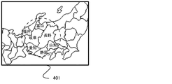
図9は、このようなドキュメント106の一部106aをクライアント装置102で撮像した際に画面102aに表示されるドキュメント401の例を示す図である。
撮像された映像中の全てのマーカに対応するコンテンツ情報を重畳させて表示する場合には、例えば図10に示すように、映像中に多くのマーカが存在している場合には、多くのコンテンツ情報が撮像された映像に重畳されて表示される。この図10ではマーカに対応するコンテンツが県名のみである場合について示しているが、コンテンツ情報として県に関する情報を含む場合には、更に多くのコンテンツ情報が表示されることになり、クライアント装置の画面が情報で埋もれてしまう状態になってしまう。
FIG. 8 is a diagram illustrating an example of a document in which a marker (object) is embedded.
FIG. 9 is a diagram illustrating an example of a
When content information corresponding to all markers in the captured video is superimposed and displayed, for example, as shown in FIG. 10, if there are many markers in the video, a large amount of content is displayed. Information is displayed superimposed on the captured image. FIG. 10 shows the case where the content corresponding to the marker is only the prefecture name. However, when the content information includes information about the prefecture, more content information is displayed. The screen will be buried with information.
これに対し、図11、図12、図13は図4に示すフローチャートの処理を実行した際に画面102aに表示されるドキュメント401の例である。
図11は、クライアント装置102が動きを検出していない状態でのコンテンツ情報の表示例を示している。
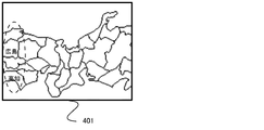
図12は、クライアント装置102が左向きに「低速移動」している状態でのコンテンツ情報の表示例を示している。
図13は、クライアント装置102が左向きに「中速移動」している状態でのコンテンツ情報の表示例を示している。
On the other hand, FIGS. 11, 12, and 13 show examples of the
FIG. 11 shows a display example of content information in a state where the
FIG. 12 shows a display example of content information in a state where the
FIG. 13 shows a display example of content information in a state where the
これらの図に示されているように、この情報表示システムでは、クライアント装置102が移動する速度と方向に応じてマーカ検出領域の大きさ、位置、形状を変更し、マーカ検出領域内にあるマーカに対応するコンテンツ情報を表示する。このような動作とすることで、ユーザにとって適度な情報を表示するようになっている。例えばユーザがドキュメント中の所望の位置が画面に映るようにクライアント装置102を移動させると、この移動に追従して、マーカ検出領域の大きさ、位置、形状が変化する。ユーザがクライアント装置102を移動する際には、最初は目的となるドキュメント中の場所をめがけて勢いよく(例えば「中速移動」で)移動させるが、目的の場所に近付くに従って(例えば「低速移動」から「停止」に)減速させるものと思われる。このようにクライアント装置を移動させた場合、最初は、移動方向寄りで狭いマーカ検出領域が設定されるが、減速されるに従って中央部の大きいマーカ検出領域が設定される。
As shown in these figures, in this information display system, the size, position, and shape of the marker detection area are changed in accordance with the speed and direction in which the
以上説明したとおり、第1実施形態に係るクライアント装置102によれば、クライアント装置102の移動状態に応じて、ユーザが注視していると想定される画面上の領域をマーカ検出領域としている。このように、大きさや位置や形状が変わるマーカ検出領域内のマーカに対応するコンテンツ情報を撮像された映像に重畳させて表示することで、表示すべきコンテンツ情報を適度に抑えることができる。このため、多くのコンテンツ情報が表示されることによる煩わしさを軽減することができる。また、表示するコンテンツ情報を限定することにより、表示の処理負荷を軽減させることができる。
As described above, according to the
<第2実施形態>
第1実施形態では、撮像中の操作によってマーカ検出領域の大きさや位置や形状を変えることで、表示すべきコンテンツ情報を限定する例を示した。第2実施形態では撮像中の操作によってマーカ検知の優先度や重要度を変えることで、コンテンツ情報の表示に変化を与える例を示す。なお、この第2実施形態の情報表示システムのネットワーク構成、内部構成、機能ブロック図は第1実施形態と同様であるため説明を省略する。
Second Embodiment
In the first embodiment, an example is shown in which the content information to be displayed is limited by changing the size, position, and shape of the marker detection region by an operation during imaging. The second embodiment shows an example in which the display of content information is changed by changing the priority and importance of marker detection by an operation during imaging. Note that the network configuration, internal configuration, and functional block diagram of the information display system of the second embodiment are the same as those of the first embodiment, and a description thereof will be omitted.
図14は第2実施形態に係る情報表示システムのクライアント装置(情報表示装置)102の動作を示すフローチャートである。フローチャートは、CPUが制御プログラムを実行することにより実現される。なお、ステップS1301からステップS1304までの処理は図4中のクライアント装置の移動状態を判定するステップS401からステップS404までの処理と同じであるため説明を省略する。
ステップS1305及びステップS1306では、ステップS1301からS1304までで検知したクライアント装置の移動状態に応じてマーカを検出するマーカ検出領域(本実施例では撮像された映像全体)を重要度によって区分し、重要度の高い領域(マーカ優先検出領域[変更領域])の大きさ、位置、形状の変更処理を行う。
FIG. 14 is a flowchart showing the operation of the client device (information display device) 102 of the information display system according to the second embodiment. The flowchart is realized by the CPU executing the control program. Note that the processing from step S1301 to step S1304 is the same as the processing from step S401 to step S404 for determining the movement state of the client apparatus in FIG.
In step S1305 and step S1306, a marker detection area (in the present embodiment, the entire captured image) for detecting a marker is classified according to importance according to the movement state of the client device detected in steps S1301 to S1304. Change processing of the size, position, and shape of the high area (marker priority detection area [change area]).
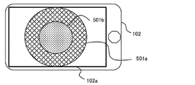
図15は。ステップS1301において、静止状態又は微速移動と判定された状態の例を示している。このときマーカを検出するマーカ検出領域は撮像された映像の全体とするが、ユーザは撮像された映像の領域の中央ほど注視していると考えられる。このため、制御部303(表示処理手段、表示変更手段)は、映像の中央部を、重要度が高いマーカ優先検出領域501aとし、さらにその中央側をより重要度が高いマーカ最優先検出領域501bとして扱う。
FIG. In step S1301, an example of a state determined to be a stationary state or a slow movement is illustrated. At this time, the marker detection area for detecting the marker is the entire captured image, but it is considered that the user is gazing toward the center of the captured image area. For this reason, the control unit 303 (display processing unit, display change unit) sets the central part of the video as the marker
図16はステップS1302で移動速度が低速と判断され、ステップS1304で移動方向が左方向と判断された状態の例を示している。この場合は、ユーザはクライアント装置102の画面102aの左側に表示される情報を注視していると考えられる。このため、制御部303は、マーカ優先検出領域501a及びマーカ最優先検出領域501bを画面102aの中心より左側に偏った領域とし、重要度が高いものとして扱う。
FIG. 16 shows an example of a state in which the moving speed is determined to be low in step S1302 and the moving direction is determined to be left in step S1304. In this case, it is considered that the user is watching the information displayed on the left side of the
ステップS1307では、マーカ検出領域内に(画面102aに表示されている映像全体のどこかに)マーカが存在しているかを確認する。
ステップS1308では、検出したマーカに対応するコンテンツ情報を優先度、重要度に応じて強調して、撮像された映像に重畳させて画面102aに出力する。なお、優先度、重要度は、マーカ優先検出領域501a内、あるいはマーカ最優先検出領域501b内であるか否かで判断する。
例えば、マーカ優先検出領域501a内のマーカに対応するコンテンツ情報は、マーカ優先検出領域501a外のマーカに対応するコンテンツ情報の文字サイズより1ポイント大きいサイズで画面102aに出力される。そして、マーカ最優先検出領域501b内のマーカに対応するコンテンツ情報は、マーカ優先検出領域501a外のマーカに対応するコンテンツ情報の文字サイズより2ポイント大きいサイズで画面102aに出力される。
このように、コンテンツ情報の出力が終了した後、制御部303はプロセスの最初(S1301)に戻り、上述の処理を繰り返す。
これにより、クライアント装置102の移動に応じて、撮像された映像中のマーカ優先検出領域501a及びマーカ最優先検出領域501b内のマーカに対応するコンテンツ情報が、強調されて、撮像された映像に重畳されて表示される。
In step S1307, it is confirmed whether a marker exists in the marker detection area (somewhere in the entire image displayed on the
In step S1308, the content information corresponding to the detected marker is emphasized according to priority and importance, and is superimposed on the captured image and output to the
For example, the content information corresponding to the marker in the marker
Thus, after the output of the content information is completed, the
Accordingly, content information corresponding to the markers in the marker
図17は、図14の動作フローチャートの処理を実行した際に画面102aに表示されるドキュメント401の例である。この図17は、クライアント装置102が動きを検出していない状態でのコンテンツ情報の表示例を示している。
この図に示すように、制御部303は、重要度の高い領域のコンテンツ情報ほど大きく表示され、逆に重要度の低い情報が小さく表示されるようにコンテンツ情報の表示態様を変化させる。
この図の例では、文字サイズを大中小の3つとした。そして、
マーカ優先検出領域501a外のマーカに対応するコンテンツ情報の文字(例えば、山形)のサイズを小とし、
マーカ優先検出領域501a内かつマーカ最優先検出領域501b外のマーカに対応するコンテンツ情報の文字(例えば、埼玉)のサイズを中とし、
マーカ最優先検出領域501b内のマーカに対応するコンテンツ情報の文字(例えば、長野)のサイズを大とした。
第1実施形態におけるマーカ検出領域の変更と同様に、これらマーカ優先検出領域およびマーカ最優先検出領域の位置、大きさ、形状はクライアント装置102の移動に追従して変更される。
FIG. 17 is an example of a
As shown in this figure, the
In the example of this figure, the character size is three large, medium and small. And
The size of the character (for example, Yamagata) of the content information corresponding to the marker outside the marker
The size of the character (for example, Saitama) of the content information corresponding to the marker in the marker
The size of the character (for example, Nagano) of the content information corresponding to the marker in the marker highest
Similar to the change of the marker detection area in the first embodiment, the positions, sizes, and shapes of the marker priority detection area and the marker highest priority detection area are changed following the movement of the
ユーザがドキュメント中の所望の位置が画面に映るようにクライアント装置102を移動させ際には、最初は目的となるドキュメント中の場所をめがけて勢いよく移動させるが、目的の場所に近付くに従って減速させるものと思われる。このような場合、最初は移動方向寄りで狭い領域が重要度の高いマーカ優先検出領域501a及びマーカ最優先検出領域501bとして設定される。減速されるに従って、中央部の領域が重要度の高いマーカ優先検出領域501a及びマーカ最優先検出領域501bとして設定される。このような動作とすることで、ユーザが注視している箇所を見やすく表示し、それ以外の場所も表示はされているが、注視している箇所より目立たないようにするため、ユーザに負担がかからない効果がある。
When the user moves the
なお、第2実施形態では、マーカ検出領域を3種類の優先度(マーカ優先検出領域501a、501b及びそれ以外の領域)で区分した例を示しているが、優先度数には制限はなく2個以上であればいくつでも構わない。さらに、撮像された映像中の総マーカ数などの環境によって優先度数を変えることで、注視していない箇所の情報を抑えることができる。
In the second embodiment, the marker detection area is divided into three types of priority (marker
また、先述では優先度に応じてコンテンツ情報の表示の大きさを変える例を挙げたが、コンテンツ情報の表示割合を変えてもよい。例えば、図17で言うと、優先度の高い領域ではコンテンツ情報として持っている県名と県に関する情報を全て表示する。優先度の低い領域ではコンテンツ情報として県名と県に関する情報は持っているのだが、表示は県名のみ表示する。このように、優先度に応じて本来持っている情報をすべて表示するのか一部表示するのかという表示方法でも問題ない。このようにすることで、表示内容を一部のみ扱う箇所も存在するために、システムの処理側の負荷も抑えることができる。 In the above description, the example in which the display size of the content information is changed according to the priority is given. However, the display ratio of the content information may be changed. For example, referring to FIG. 17, in the high priority area, all the prefecture names and information related to the prefectures are displayed as content information. The low priority area has the prefecture name and information about the prefecture as the content information, but only the prefecture name is displayed. As described above, there is no problem with the display method of displaying all or part of the information originally possessed according to the priority. By doing so, there is a part where only a part of the display content is handled, so that the load on the processing side of the system can be suppressed.
以上説明したとおり、第2実施形態に係るクライアント装置102によれば、クライアント装置102を使った撮像、閲覧操作によってユーザの注視場所が特定できる。そのため、注視場所によってコンテンツ情報の大きさ、情報の詳細さや情報量などの表示形態を変えることで、表示上、見やすくすることができる。また、情報の詳細さ、あるいは、情報量を低減させるように表示形態を変えることで、処理負荷を軽減させることができる。
As described above, according to the
<その他の実施形態>
クライアント装置102の撮像領域内に含まれるマーカ及びコンテンツ情報の密集度または割合によって第1実施形態及び第2実施形態の処理を実施するかを判断しても構わない。つまり、マーカの割合(オブジェクトの割合)が閾値を超えない場合は、第1実施形態の処理も第2実施形態の処理も実施しなくても良い。「オブジェクトの割合」とは、例えば下記式によって算出する。
オブジェクトの割合=(撮像領域内に含まれるオブジェクトの数)/(表示画面102aのサイズによって予め決められたオブジェクトの数)
<Other embodiments>
Whether the processing of the first embodiment and the second embodiment is to be performed may be determined based on the density or ratio of markers and content information included in the imaging area of the
Object ratio = (number of objects included in the imaging region) / (number of objects determined in advance by the size of the
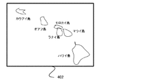
例えば図18はマーカの密集度の低いドキュメントを撮像した例である。
このように、マーカの密集度が低い場合には、全てのコンテンツ情報を表示しても煩わしくないと想定される。このため、この実施形態では、上述の図4あるいは図14に示す処理を実行する前に、撮像映像中のマーカの数を検出し、検出したマーカの数に応じてマーカ検出領域の設定を行う。具体的には、クライアント装置は、撮像装置209によって撮像した映像中の全てのマーカの数を検出する。検出されたマーカの数が所定の閾値(例えば5〜20程度)より少ない場合には、図4あるいは図14に示す処理の代わりに、撮像映像中の全てのマーカに対応するコンテンツ情報を重畳させて表示する。
For example, FIG. 18 shows an example of imaging a document with a low marker density.
Thus, when the marker density is low, it is assumed that it is not troublesome to display all the content information. Therefore, in this embodiment, before executing the processing shown in FIG. 4 or FIG. 14, the number of markers in the captured image is detected, and the marker detection area is set according to the number of detected markers. . Specifically, the client device detects the number of all markers in the video imaged by the
マーカの密集度が少ないときにマーカの多いときと同じ処理をすると、通常の表示処理より負荷を増加させる可能性があるが、このような動作とすることで、負荷の増加を抑制することができる。また、ユーザ側からも、マーカの密集度が少ないということは全てのコンテンツ情報を表示しても煩わしくないため、負担が少ないまま一覧することができる。 If the same processing as when there are many markers when the marker density is low, there is a possibility of increasing the load compared to normal display processing. it can. Also, from the user side, the fact that the marker density is low is not troublesome even if all the content information is displayed, so that the list can be displayed with a small burden.
以上、実施形態の例を詳述したが、本発明は例えば、システム、装置、方法、プログラム又は記録媒体(記憶媒体)等としての実施態様をとることが可能である。具体的には、複数の機器(例えば、ホストコンピュータ、インタフェース機器、撮像装置、Webアプリケーション等)から構成されるシステムに適用することも、一つの機器からなる装置に適用することも可能である。 As mentioned above, although the example of embodiment was explained in full detail, this invention can take the embodiment as a system, an apparatus, a method, a program, or a recording medium (storage medium) etc., for example. Specifically, the present invention can be applied to a system composed of a plurality of devices (for example, a host computer, an interface device, an imaging device, a Web application, etc.), or can be applied to a device composed of a single device.
また、前述した実施形態の機能を実現するソフトウェアのプログラムコード(コンピュータプログラム)を記録した記録媒体(または記憶媒体)を、システムあるいは装置に供給する。そして、そのシステムあるいは装置のコンピュータ(またはCPUやMPU)が記録媒体に格納されたプログラムコードを読み出し実行する。この場合、記録媒体から読み出されたプログラムコードの実行により実現される機能部が前述した実施形態の機能を実現することになる。 Further, a recording medium (or storage medium) in which a program code (computer program) of software that realizes the functions of the above-described embodiments is recorded is supplied to the system or apparatus. Then, the computer (or CPU or MPU) of the system or apparatus reads and executes the program code stored in the recording medium. In this case, the function unit realized by executing the program code read from the recording medium realizes the function of the above-described embodiment.
102 表示装置
102a 表示装置の表示部
501、501a 表示装置が優先的に表示を行う領域
501b 表示装置がさらに優先的に表示を行う領域
401、402 マーカが埋め込まれたドキュメント
102
Claims (14)
撮像方向の移動方向を計測する計測手段と、
前記計測手段で計測された移動方向によって前記撮像映像における対象領域の位置を変化させる変更手段と、
前記撮像映像中のオブジェクトを認識する認識手段と、
前記対象領域の内にある前記オブジェクトに関連する情報を前記撮像映像に重畳させ、前記対象領域の外にある前記オブジェクトに関連する情報を前記撮像映像に重畳させない表示制御手段と、
を備えることを特徴とする情報表示装置。 An information display device that displays information superimposed on a captured image,
Measuring means for measuring the moving direction of the imaging direction;
Changing means for changing the position of the target area in the captured image according to the moving direction measured by the measuring means;
Recognition means for recognizing an object in the captured video;
The information relating to the object located within the target area is superimposed on the imaging Film image, a display control means that is not the information relating to the objects outside of the target area is superimposed on the captured image,
An information display device comprising:
前記変更手段は、前記計測手段で計測された速度が第1の閾値以下の場合には前記対象領域を中央付近の第1の領域とし、前記第1の閾値を超えた場合には前記対象領域を前記計測手段で計測された移動方向に偏った第2の領域とすることを特徴とする請求項1に記載の情報表示装置。 The measuring means further measures the speed,
The changing means sets the target area as a first area near the center when the speed measured by the measuring means is equal to or less than a first threshold, and sets the target area when the speed exceeds the first threshold. The information display device according to claim 1, wherein the second region is biased in a moving direction measured by the measuring unit.
撮像方向の移動方向を計測する計測手段と、
前記計測手段で計測された移動方向によって前記撮像映像における対象領域の位置を変化させる変更手段と、
前記撮像映像中のオブジェクトを認識する認識手段と、
前記対象領域の内にある前記オブジェクトに関連する情報の表示形態と、
前記対象領域の外にある前記オブジェクトに関連する情報の表示形態とを、異なる表示形態として前記撮像映像に重畳させる表示制御手段と、
を備えることを特徴とする情報表示装置。 An information display device that displays information superimposed on a captured image,
Measuring means for measuring the moving direction of the imaging direction;
Changing means for changing the position of the target area in the captured image according to the moving direction measured by the measuring means;
Recognition means for recognizing an object in the captured video;
A display form of information relating to the prior Symbol object Ru inner near the target area,
Display control means for the display form of the information associated with the outer near Ru before Symbol object, is superimposed on the captured image as a display form different from said target area,
An information display device comprising:
前記変更手段は、前記計測手段で計測された速度が第1の閾値以下の場合には前記対象領域を中央付近の第1の領域とし、前記第1の閾値を超えた場合には前記対象領域を前記計測手段で計測された移動方向に偏った第2の領域とすることを特徴とする請求項5に記載の情報表示装置。 The measuring means further measures the speed,
The changing means sets the target area as a first area near the center when the speed measured by the measuring means is equal to or less than a first threshold, and sets the target area when the speed exceeds the first threshold. The information display device according to claim 5, wherein the second area is biased in a moving direction measured by the measuring unit.
前記計測手段は、前記移動する速度及び方向を計測せず、
前記変更手段は、前記対象領域を前記撮像映像の全ての領域とし、
前記認識手段は、前記撮像映像中の全てのオブジェクトを認識し、
前記表示制御手段は、前記撮像映像中の全てのオブジェクトに関連する情報を前記撮像映像に重畳させる、ことを特徴とする請求項1乃至6のいずれか一項に記載の情報表示装置。 If the percentage of objects present in the captured video does not exceed the threshold,
The measuring means does not measure the moving speed and direction,
The changing means sets the target area as all areas of the captured video,
The recognition means recognizes all objects in the captured video,
The information display device according to claim 1, wherein the display control unit superimposes information related to all objects in the captured video on the captured video.
前記情報表示装置は、
撮像方向の移動方向を計測する計測手段と、
前記計測手段で計測された移動方向によって前記撮像映像における対象領域の位置を変化させる変更手段と、
前記撮像映像中のオブジェクトを認識する認識手段と、
前記認識手段によって認識された前記オブジェクトの認識情報を前記情報処理装置に送信する送信手段と、
前記情報処理装置から前記オブジェクトに関連する情報を受信する受信手段と、
前記受信した、前記オブジェクトに関連する情報を前記撮像映像の前記対象領域の内にあるオブジェクトに重畳させ、前記対象領域の外にあるオブジェクトに重畳させない表示制御手段と、を備え、
前記情報処理装置は、
前記情報表示装置から前記オブジェクトの認識情報を受信する受信手段と、
前記情報表示装置に前記オブジェクトに関連する情報を送信する送信手段と、
を備えることを特徴とする情報表示システム。 An information display system composed of an information display device that superimposes and displays information on a captured video and an information processing device connected via a network,
The information display device includes:
Measuring means for measuring the moving direction of the imaging direction;
Changing means for changing the position of the target area in the captured image according to the moving direction measured by the measuring means;
Recognition means for recognizing an object in the captured video;
Transmitting means for transmitting recognition information of the object recognized by the recognition means to the information processing apparatus;
Receiving means for receiving information related to the object from the information processing apparatus;
Display control means that superimposes the received information related to the object on an object within the target area of the captured video and does not superimpose on an object outside the target area ;
The information processing apparatus includes:
Receiving means for receiving recognition information of the object from the information display device;
Transmitting means for transmitting information related to the object to the information display device;
An information display system comprising:
計測手段が、撮像方向の移動方向を計測する計測工程と、
変更手段が、前記計測工程により計測された移動方向によって前記撮像映像における対象領域の位置を変化させる変更工程と、
認識手段が、前記撮像映像中のオブジェクトを認識する認識工程と、
表示制御手段が、前記対象領域の内にある前記オブジェクトに関連する情報を前記撮像映像に重畳させ、前記対象領域の外にある前記オブジェクトに関連する情報を前記撮像映像に重畳させない表示制御工程と、
を有することを特徴とする情報表示装置の制御方法。 A method of controlling an information display device that displays information superimposed on a captured image,
A measuring step in which the measuring means measures the moving direction of the imaging direction;
A changing step for changing the position of the target area in the captured image according to the moving direction measured in the measuring step;
A recognition step for recognizing an object in the captured video;
Display control means, the information related to the object to be within the target area is superimposed on the imaging Film image, the object region display control step of the information relating to the objects outside does not overlap the captured image of When,
A control method for an information display device, comprising:
計測手段が、撮像方向の移動方向を計測する計測工程と、
変更手段が、前記計測工程により計測された移動方向によって前記撮像映像における対象領域の位置を変化させる変更工程と、
認識手段が、前記撮像映像中のオブジェクトを認識する認識工程と、
表示制御手段が、
前記対象領域の内にある前記オブジェクトに関連する情報の表示形態と、
前記対象領域の外にある前記オブジェクトに関連する情報の表示形態とを、異なる表示形態として前記撮像映像に重畳させる表示制御工程と、
を有することを特徴とする情報表示装置の制御方法。 A method of controlling an information display device that displays information superimposed on a captured image,
A measuring step in which the measuring means measures the moving direction of the imaging direction;
A changing step for changing the position of the target area in the captured image according to the moving direction measured in the measuring step;
A recognition step for recognizing an object in the captured video;
The display control means
A display form of information relating to the prior Symbol object Ru inner near the target area,
And a display control step of the display form of the information associated with the outer near Ru before Symbol object, is superimposed on the captured image as a display form different from said target area,
A control method for an information display device, comprising:
前記情報表示装置の計測手段が、撮像方向の移動方向を計測する計測工程と、
前記情報表示装置の変更手段が、前記計測工程により計測された移動方向によって前記撮像映像における対象領域の位置を変化させる変更工程と、
前記情報表示装置の認識手段が、前記撮像映像中のオブジェクトを認識する認識工程と、
前記情報表示装置の送信手段が、前記オブジェクトの認識情報を前記情報処理装置に送信する送信工程と、
前記情報処理装置の受信手段が、前記情報表示装置から前記オブジェクトの認識情報を受信する受信工程と、
前記情報処理装置の送信手段が、前記情報表示装置に前記オブジェクトに関連する情報を送信する送信工程と、
前記情報表示装置の受信手段が、前記情報処理装置から前記オブジェクトに関連する情報を受信する受信工程と、
前記情報表示装置の表示制御手段が、前記対象領域の内にある前記オブジェクトに関連する情報を前記撮像映像の前記対象領域に重畳させ、前記対象領域の外にある前記オブジェクトに関連する情報を前記撮像映像に重畳させない表示制御工程と、
を有することを特徴とする情報表示システムの制御方法。 A control method for an information display system comprising an information display device that displays information superimposed on a captured video and an information processing device connected via a network,
A measuring step in which the measuring means of the information display device measures the moving direction of the imaging direction;
A changing step in which the changing means of the information display device changes the position of the target area in the captured image according to the moving direction measured in the measuring step;
A recognition step of recognizing the object in the captured video by the recognition means of the information display device;
Transmitting means of the information display apparatus, a transmission step of transmitting identification information of the previous SL object to the information processing apparatus,
A receiving step in which the receiving means of the information processing device receives the recognition information of the object from the information display device;
A transmission step of transmitting information related to the object to the information display device by the transmission means of the information processing device;
A receiving step in which the receiving means of the information display device receives information related to the object from the information processing device;
Display control means of the information display device, wherein the information related to the object to be within the target area is superimposed on the target area of the captured image, information relating to the objects outside of the target region A display control process that is not superimposed on the captured image ;
A control method for an information display system, comprising:
Priority Applications (3)
| Application Number | Priority Date | Filing Date | Title |
|---|---|---|---|
| JP2012289183A JP6049452B2 (en) | 2012-12-29 | 2012-12-29 | Information display device, information display system, control method thereof, and program |
| US14/140,832 US9721538B2 (en) | 2012-12-29 | 2013-12-26 | Information display apparatus, information display system, control method thereof, and program |
| US15/630,510 US10410607B2 (en) | 2012-12-29 | 2017-06-22 | Information display apparatus that superposes information on an imaged image and displays the information and the imaged image, and related information display system, control method and program |
Applications Claiming Priority (1)
| Application Number | Priority Date | Filing Date | Title |
|---|---|---|---|
| JP2012289183A JP6049452B2 (en) | 2012-12-29 | 2012-12-29 | Information display device, information display system, control method thereof, and program |
Publications (3)
| Publication Number | Publication Date |
|---|---|
| JP2014130551A JP2014130551A (en) | 2014-07-10 |
| JP2014130551A5 JP2014130551A5 (en) | 2016-02-12 |
| JP6049452B2 true JP6049452B2 (en) | 2016-12-21 |
Family
ID=51016697
Family Applications (1)
| Application Number | Title | Priority Date | Filing Date |
|---|---|---|---|
| JP2012289183A Active JP6049452B2 (en) | 2012-12-29 | 2012-12-29 | Information display device, information display system, control method thereof, and program |
Country Status (2)
| Country | Link |
|---|---|
| US (2) | US9721538B2 (en) |
| JP (1) | JP6049452B2 (en) |
Families Citing this family (7)
| Publication number | Priority date | Publication date | Assignee | Title |
|---|---|---|---|---|
| JP6651719B2 (en) * | 2015-07-02 | 2020-02-19 | 富士通株式会社 | Display control method, display control program, and information processing terminal |
| US10379606B2 (en) * | 2017-03-30 | 2019-08-13 | Microsoft Technology Licensing, Llc | Hologram anchor prioritization |
| JP7022554B2 (en) | 2017-10-03 | 2022-02-18 | キヤノン株式会社 | Image processing equipment and its control method, program |
| JP6849826B2 (en) * | 2018-01-30 | 2021-03-31 | 株式会社ソニー・インタラクティブエンタテインメント | Image processing device and display image generation method |
| US11176911B2 (en) * | 2018-03-30 | 2021-11-16 | Sony Corporation | Information processing apparatus, information processing method, program, and head-mounted display |
| JP7413077B2 (en) * | 2020-02-27 | 2024-01-15 | キヤノン株式会社 | Head-mounted display, control method, information processing device, information processing method, and program |
| CN111855155B (en) * | 2020-07-23 | 2022-05-31 | 深圳创维-Rgb电子有限公司 | Detection method and detection device for display fault and readable storage medium |
Family Cites Families (13)
| Publication number | Priority date | Publication date | Assignee | Title |
|---|---|---|---|---|
| US6445409B1 (en) * | 1997-05-14 | 2002-09-03 | Hitachi Denshi Kabushiki Kaisha | Method of distinguishing a moving object and apparatus of tracking and monitoring a moving object |
| WO2003032143A2 (en) * | 2001-10-12 | 2003-04-17 | Hrl Laboratories, Llc | Vision-based pointer tracking method and apparatus |
| JP2004178158A (en) * | 2002-11-26 | 2004-06-24 | Nissan Motor Co Ltd | Device for preventing deviation from traffic lane |
| US7301528B2 (en) * | 2004-03-23 | 2007-11-27 | Fujitsu Limited | Distinguishing tilt and translation motion components in handheld devices |
| JP4061379B2 (en) * | 2004-11-29 | 2008-03-19 | 国立大学法人広島大学 | Information processing apparatus, portable terminal, information processing method, information processing program, and computer-readable recording medium |
| JP4413235B2 (en) * | 2006-02-22 | 2010-02-10 | 三洋電機株式会社 | Electronic camera |
| JP2011242816A (en) * | 2008-09-09 | 2011-12-01 | Tonchidot Corp | System capable of adding virtual information to visual field information and displaying it |
| US8274544B2 (en) * | 2009-03-23 | 2012-09-25 | Eastman Kodak Company | Automated videography systems |
| US8964298B2 (en) * | 2010-02-28 | 2015-02-24 | Microsoft Corporation | Video display modification based on sensor input for a see-through near-to-eye display |
| US8963954B2 (en) * | 2010-06-30 | 2015-02-24 | Nokia Corporation | Methods, apparatuses and computer program products for providing a constant level of information in augmented reality |
| JP2012058838A (en) | 2010-09-06 | 2012-03-22 | Sony Corp | Image processor, program, and image processing method |
| JP5014494B2 (en) * | 2011-01-21 | 2012-08-29 | パナソニック株式会社 | Information processing apparatus, augmented reality system, information processing method, and information processing program |
| US9996150B2 (en) * | 2012-12-19 | 2018-06-12 | Qualcomm Incorporated | Enabling augmented reality using eye gaze tracking |
-
2012
- 2012-12-29 JP JP2012289183A patent/JP6049452B2/en active Active
-
2013
- 2013-12-26 US US14/140,832 patent/US9721538B2/en not_active Expired - Fee Related
-
2017
- 2017-06-22 US US15/630,510 patent/US10410607B2/en active Active
Also Published As
| Publication number | Publication date |
|---|---|
| US9721538B2 (en) | 2017-08-01 |
| JP2014130551A (en) | 2014-07-10 |
| US10410607B2 (en) | 2019-09-10 |
| US20170287445A1 (en) | 2017-10-05 |
| US20140184641A1 (en) | 2014-07-03 |
Similar Documents
| Publication | Publication Date | Title |
|---|---|---|
| JP6049452B2 (en) | Information display device, information display system, control method thereof, and program | |
| EP3346696B1 (en) | Image capturing method and electronic device | |
| KR102171082B1 (en) | Method for processing fingerprint and an electronic device thereof | |
| EP2864932B1 (en) | Fingertip location for gesture input | |
| US9304728B2 (en) | Generating a map of image forming devices on a mobile device | |
| US20170201709A1 (en) | Information processing apparatus, information processing method, and program | |
| KR102576654B1 (en) | Electronic apparatus and controlling method thereof | |
| KR20180109229A (en) | Method and apparatus for providing augmented reality function in electornic device | |
| US10789033B2 (en) | System and method for providing widget | |
| CN105009034A (en) | Information processing apparatus, information processing method, and program | |
| US20160349972A1 (en) | Data browse apparatus, data browse method, and storage medium | |
| CN104252228A (en) | Display apparatus and method for controlling display apparatus thereof | |
| US9406136B2 (en) | Information processing device, information processing method and storage medium for identifying communication counterpart based on image including person | |
| CN116368559A (en) | Rotating image viewer | |
| EP3327551A1 (en) | Electronic device for displaying image and method for controlling the same | |
| CN110650210B (en) | Image data acquisition method, device and storage medium | |
| US20150268735A1 (en) | User interface device and user interface method | |
| KR20140103021A (en) | Object recognition device | |
| KR102122793B1 (en) | Electronic device and method for image processing in electronic device | |
| US20150042621A1 (en) | Method and apparatus for controlling 3d object | |
| CN112101297A (en) | Training data set determination method, behavior analysis method, device, system and medium | |
| US20230224451A1 (en) | Information processing apparatus, information processing method, and program | |
| US20150106492A1 (en) | Electronic device, display method for electronic device, and computer-readable recording medium | |
| KR101761487B1 (en) | Head mounted display device and method for operating thereof | |
| JP2014174643A (en) | Image processing system, control method therefor, image processing device, and image processing method |
Legal Events
| Date | Code | Title | Description |
|---|---|---|---|
| A521 | Request for written amendment filed |
Free format text: JAPANESE INTERMEDIATE CODE: A523 Effective date: 20151221 |
|
| A621 | Written request for application examination |
Free format text: JAPANESE INTERMEDIATE CODE: A621 Effective date: 20151221 |
|
| A977 | Report on retrieval |
Free format text: JAPANESE INTERMEDIATE CODE: A971007 Effective date: 20161019 |
|
| TRDD | Decision of grant or rejection written | ||
| A01 | Written decision to grant a patent or to grant a registration (utility model) |
Free format text: JAPANESE INTERMEDIATE CODE: A01 Effective date: 20161025 |
|
| A61 | First payment of annual fees (during grant procedure) |
Free format text: JAPANESE INTERMEDIATE CODE: A61 Effective date: 20161122 |
|
| R151 | Written notification of patent or utility model registration |
Ref document number: 6049452 Country of ref document: JP Free format text: JAPANESE INTERMEDIATE CODE: R151 |
|
| RD03 | Notification of appointment of power of attorney |
Free format text: JAPANESE INTERMEDIATE CODE: R3D03 |