JP6048301B2 - Electronics - Google Patents
Electronics Download PDFInfo
- Publication number
- JP6048301B2 JP6048301B2 JP2013092306A JP2013092306A JP6048301B2 JP 6048301 B2 JP6048301 B2 JP 6048301B2 JP 2013092306 A JP2013092306 A JP 2013092306A JP 2013092306 A JP2013092306 A JP 2013092306A JP 6048301 B2 JP6048301 B2 JP 6048301B2
- Authority
- JP
- Japan
- Prior art keywords
- heat
- image sensor
- camera body
- image
- heat conductive
- Prior art date
- Legal status (The legal status is an assumption and is not a legal conclusion. Google has not performed a legal analysis and makes no representation as to the accuracy of the status listed.)
- Active
Links
- 238000003384 imaging method Methods 0.000 claims description 17
- 230000003287 optical effect Effects 0.000 description 6
- 230000017525 heat dissipation Effects 0.000 description 5
- 238000004519 manufacturing process Methods 0.000 description 5
- 239000011231 conductive filler Substances 0.000 description 2
- 239000000463 material Substances 0.000 description 2
- 239000002184 metal Substances 0.000 description 2
- 238000006243 chemical reaction Methods 0.000 description 1
- 238000010586 diagram Methods 0.000 description 1
- 239000013013 elastic material Substances 0.000 description 1
- 230000020169 heat generation Effects 0.000 description 1
- 239000007769 metal material Substances 0.000 description 1
- 239000005394 sealing glass Substances 0.000 description 1
Images


Landscapes
- Camera Bodies And Camera Details Or Accessories (AREA)
- Studio Devices (AREA)
- Physics & Mathematics (AREA)
- General Physics & Mathematics (AREA)
Description
本発明は、放熱構造を有する電子機器に関するものである。 The present invention relates to an electronic device having a heat dissipation structure.
従来のデジタルカメラにおいては、撮像素子の高画素化や動画像データの高フレームレート化等によって撮像素子並びに画像処理回路部での発熱が問題となっている。特に撮像素子が高温になることで熱ノイズが発生して撮像した画像の画質を悪化させている。そのため、撮像素子を出来るだけ低温状態に維持するための放熱構造が望まれている。ここで放熱構造として撮像素子の取付け位置を調整する機構を搭載する場合には、カメラの大型化を防ぐ機構を採用しなければならないことから、弾性部材を用いた撮像素子取付機構に弾性変形可能な熱伝導シートを組み合わせた放熱構造が提案されている(例えば、特許文献1参照)。 In the conventional digital camera, heat generation in the image sensor and the image processing circuit unit has become a problem due to the increase in the number of pixels of the image sensor and the increase in the frame rate of moving image data. In particular, when the image sensor becomes high temperature, thermal noise is generated and the image quality of the captured image is deteriorated. Therefore, there is a demand for a heat dissipation structure for keeping the image sensor as low as possible. When mounting a mechanism that adjusts the mounting position of the image sensor as a heat dissipation structure, a mechanism that prevents the camera from becoming large must be used, so it can be elastically deformed to an image sensor mounting mechanism that uses an elastic member. A heat dissipating structure combining various heat conductive sheets has been proposed (see, for example, Patent Document 1).
しかし、上述のデジタルカメラにおいては、撮像素子を取付ける取付部とは別に熱伝導シートを配置しているため、熱伝導シートを配置するスペースを確保する必要がある。また撮像素子の調整移動量に追従するために弾性変形可能な熱伝導シートを厚くする必要がある。一般的に弾性材料の熱伝導率を高くすることは難しく、また部材の厚さ方向に熱を伝える場合は熱の伝わり難さを示す熱抵抗が部材の厚さに比例する。従って熱伝導シートを厚くした放熱構造ではスペース確保が必要な上に、効率的な放熱を行なうことができないという問題があった。 However, in the above-described digital camera, since the heat conductive sheet is arranged separately from the mounting portion for attaching the image pickup device, it is necessary to secure a space for arranging the heat conductive sheet. Further, in order to follow the adjustment movement amount of the image sensor, it is necessary to increase the thickness of the heat conductive sheet that can be elastically deformed. Generally, it is difficult to increase the thermal conductivity of an elastic material, and when heat is transmitted in the thickness direction of a member, the thermal resistance indicating the difficulty of heat transfer is proportional to the thickness of the member. Therefore, the heat dissipation structure with a thick heat conductive sheet has a problem that it is necessary to secure a space and it is impossible to efficiently dissipate heat.
本発明の目的は、省スペースで撮像素子の放熱を効果的に行なう放熱構造を有する電子機器を提供することである。 An object of the present invention is to provide an electronic apparatus having a heat dissipation structure that effectively radiates heat from an imaging device in a small space.
本発明の電子機器は、撮像素子を保持する保持部と、前記保持部を固定する固定部と、前記保持部の熱を前記固定部に伝達する伝熱部材とを備え、前記伝熱部材は前記固定部に対して接触した状態で移動可能に保持されている。
Electronic device of the present invention includes a storage unit storing an imaging device, and a fixing unit for fixing the holding portion, and a heat transfer member for transferring heat of the holding portion to the fixed portion, the heat transfer member It is being held so as to be moved in contact with respect to the fixed part.
本発明によれば、省スペースで撮像素子の放熱を効果的に行なうことができる。 According to the present invention, it is possible to effectively dissipate heat from the image pickup device in a space-saving manner.
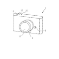
以下、図面を参照して、本発明の第1の実施の形態に係る電子機器としてのデジタルカメラについて説明する。図1は第1の実施の形態に係るデジタルカメラの前面を示す斜視図である。デジタルカメラ2の前面にはレンズ鏡筒4、レンズ鏡筒取外しボタン6が設けられている。レンズ鏡筒4は、撮影レンズ8を含む光学系を備え、デジタルカメラ2のカメラボディ20(図3参照)に着脱可能に装着されている。レンズ鏡筒取外しボタン6は、カメラボディ20に装着されたレンズ鏡筒4を取り外すときに押下される。
Hereinafter, a digital camera as an electronic apparatus according to the first embodiment of the invention will be described with reference to the drawings. FIG. 1 is a perspective view showing the front surface of the digital camera according to the first embodiment. A
デジタルカメラ2の上面には、電源をオン/オフする電源ボタン10、撮影を指示するレリーズボタン12、動画撮影の開始または停止を指示する動画撮影ボタン14が設けられている。
On the top surface of the
図2は第1の実施の形態に係るデジタルカメラの背面を示す斜視図である。デジタルカメラ2の背面には、撮影画像や各種情報を表示する表示モニター16、撮影モードを設定するための撮影モード設定ダイヤル18が設けられている。撮影モード設定ダイヤル18では、静止画像撮影モードS、動画撮影モードM、画像再生モードPを設定することができる。
FIG. 2 is a perspective view showing the back surface of the digital camera according to the first embodiment. On the back of the
図3は第1の実施の形態に係るデジタルカメラの内部構成を示す断面図である。デジタルカメラ2のカメラボディ20の前面部には、レンズ鏡筒4のレンズ側マウント部4aを締結するためのボディ側マウント部2aが設けられている。カメラボディ20の内部には、撮像素子22、撮像回路基板24、撮像素子取付部材(撮像素子固定板)26、制御回路部28が配置されている。
FIG. 3 is a cross-sectional view showing the internal configuration of the digital camera according to the first embodiment. A body
撮像素子22は、撮像センサー22a、撮像センサー22aを納める筐体22b、筐体22bの前面を封止する封止ガラス22cにより構成され、撮影レンズ8を介して撮像センサー22aの撮像面に被写体光が入射した場合、撮像センサー22aにより光電変換が行なわれ画像信号が出力される。撮像素子22の背面部は、撮像回路基板24と電気的に接続されている。撮像素子22から出力された画像信号は、撮像回路基板24を介して制御回路部28に入力されて所定の処理が行なわれ、撮影前の被写体像や撮影画像が表示モニター16に表示される。撮像回路基板24は、撮像素子22の背面の中央部に対向する部分が開口形状となっており、撮像素子22は、撮像回路基板24の開口部を介して撮像素子取付部材26に固定されている。
The
撮像素子取付部材26は、図4の平面図に示すように固定ネジ34によってカメラボディ20に固定するための3つの固定部32を有している。即ち固定部32は、固定ネジ34を貫通させる孔を有し、撮像素子取付部材26の上端中央部に1カ所、下端の左右両端部にそれぞれ1カ所の合計3カ所、設けられている。
As shown in the plan view of FIG. 4, the imaging
カメラボディ20内には、カメラボディ20の背面側に向かって突出した形状を有する、熱伝導性の高い金属によって形成されたカメラボディ側固定部36が設けられている。図5に示すように撮像素子取付部材26の固定部32とカメラボディ側固定部36との間には、熱伝導シート38、熱伝導部材40、弾性バネ42が配置されている。
In the
熱伝導シート38は、弾性変形可能な熱伝導部材としてのシート材であって固定部32と熱伝導部材40とに密着した状態で配置される。なお熱伝導シート38の厚さについては後述する。
The heat
熱伝導部材40は、熱伝導性の高い金属によって形成されている。熱伝導部材40は、カメラボディ側固定部36側に開口を有する凹形状の断面形状を有し、その凹形状部分にカメラボディ側固定部36の先端部が嵌合されている。弾性バネ42は、熱伝導部材40の凹形状部分内に配置され、熱伝導部材40及び熱伝導シート38を撮像素子取付部材26側に押圧している。
The heat
上述のように撮像素子取付部材26とカメラボディ側固定部36との間に熱伝導シート38、熱伝導部材40及び弾性バネ42を配置した状態で、固定ネジ34により、撮像素子取付部材26の固定部32がカメラボディ側固定部36に固定される。
As described above, with the
カメラボディ20に対する撮像素子取付部材26の位置は、固定ネジ34の締め付け高さを変えることにより変更することが可能であり、各固定ネジ34の締め付け高さを変えることにより、撮像素子22の撮像面の傾きを変化させることができる。
The position of the image
ここで、撮像素子取付部材26の位置を変更させた場合においても、熱伝導部材40は、カメラボディ側固定部36と嵌合状態、即ちカメラボディ側固定部36に対して接触した状態を保ちながら、熱伝導シート38と共に追従する。また熱伝導シート38は、弾性変形可能な材料であるため、撮像素子固定部材26が傾いた状態であっても、撮像素子取付部材26と熱伝導部材40に対して密着状態を保ち、確実な伝熱が可能となる。
Here, even when the position of the image
次に、製造誤差による撮像素子22の傾きについて説明する。図6は製造誤差による撮像素子22の傾きの調整を示す図である。撮像素子22は、デジタルカメラ2の製造誤差により撮像センサー22aの撮像面が、図6(a)に示すように撮影レンズ8の光軸に直交する方向から傾く場合がある。そのため各固定ネジ34の締め付け高さを変化させ、撮像センサー22aの撮像面が図6(b)に示すように撮影レンズ8の光軸に直交するように、撮像素子22の傾き調整が行なわれる。
Next, the inclination of the
ここで、製造誤差によって撮像レンズ8の光軸に直交する方向から撮像センサー22aの撮像面が傾いた場合の傾きの最大角度をθをとし、撮像レンズ8の光軸から撮像素子取付部材26の固定部32の孔の中心までの長さをLとした場合、撮像センサー22aの撮像面を撮影レンズ8の光軸に直交させるためには、δ(=L・tanθ)だけ固定ネジ34の締め付け高さを変える必要がある。従って、熱伝導シート38の厚さは、δだけ弾性変形可能な厚さに決定される。これによって従来よりも薄い熱伝導シート38を配置することができる。
Here, when the imaging surface of the
第1の実施の形態に係るデジタルカメラ2によれば、カメラボディ側固定部36を熱伝導部材40に嵌合させ接触面積を大きくしたことにより、撮像素子22で発生した熱を撮像素子取付部材26、熱伝導シート38、熱伝導部材40を介しカメラボディ側固定部36に効率良く伝達することができるので、効率的に放熱を行なうことができる。
According to the
また熱伝導シート38を薄くしたことにより、熱伝導シート38から熱伝導部材40へ熱が伝達し易くなるので、効率的に放熱を行なうことができる。また熱伝導シート38を薄くしたことによりコストを低減することができ、またデジタルカメラ2内部における省スペース化を実現することができる。
Further, since the heat
なお、第1の実施の形態に係るデジタルカメラ2において、カメラボディ側固定部36と熱伝導部材40との密着度を高めるために、カメラボディ側固定部36と熱伝導部材40との間に伝熱性の充填物を充填してもよい。
In the
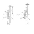
次に第2の実施の形態に係るデジタルカメラ2について説明する。図7は第2の実施の形態に係る撮像素子取付部材26の取付構造を示す図である。なお第1の実施の形態と同一の構成については同一の符号を付してその説明を省略する。また撮像素子取付部材26は、熱伝導性の高い金属材料によって形成された固定ネジ50によってカメラボディ側固定部54に固定されている。
Next, a
カメラボディ側固定部54は、カメラボディ20の背面側に突出する先端部に凹形状の開口部54aを有し、その開口部54aに固定ネジ50の先端部である伝熱部52が嵌合されている。
The camera body-
熱伝導シート38は、撮像素子取付部材26の固定部32と固定ネジ50の頭部とにより挟持されている。弾性バネ42は、撮像素子取付部材26とカメラボディ側固定部54との間に配置され、撮像素子取付部材26及び熱伝導シート38を固定ネジ50の頭部側に押圧している。熱伝導シート38は、第1の実施の形態と同様に弾性変形可能であるので、撮像素子取付部材26が傾いた状態であっても、撮像素子取付部材26と固定ネジ50に対して密着状態を保つことができる。
The heat
上述のようにデジタルカメラ2の内部を構成したため、撮像素子22で発生した熱は、撮像素子取付部材26、熱伝導シート33、固定ネジ50を介してカメラボディ側固定部54に伝達される。
Since the inside of the
第2の実施の形態に係るデジタルカメラ2によれば、固定ネジ50とカメラボディ側固定部54との接触面積を大きくすることによって、撮像素子22で発生した熱を固定ネジ50からカメラボディ側固定部54に効率的に伝達できるので、効率的に放熱を行なうことができる。
According to the
また、第1の実施の形態における熱伝導部材40を省くことができるので、さらに省スペース化を図ると共に、コストを低減することができる。
Further, since the
なお、第2の実施の形態に係るデジタルカメラ2において、固定ネジ50の伝熱部52とカメラボディ側固定部54の開口部54aとの密着度を高めるために、固定ネジ50とカメラボディ側固定部54との間に伝熱性の充填物を充填してもよい。
In the
2…デジタルカメラ、8…撮影レンズ、20…カメラボディ、22…撮像素子、26…撮像素子取付部材、34…固定ネジ、36…カメラボディ側固定部、38…熱伝導シート、40…熱伝導部材、42…弾性バネ。
DESCRIPTION OF
Claims (4)
前記保持部を固定する固定部と、
前記保持部の熱を前記固定部に伝達する伝熱部材と
を備え、
前記伝熱部材は前記固定部に対して接触した状態で移動可能に保持されている電子機器。 A holding unit for holding an imaging element,
A fixing part for fixing the holding part;
A heat transfer member that transfers heat of the holding part to the fixed part ,
Moving capable electronic device is held in a state wherein the heat transfer member is in contact with respect to the fixed part.
前記伝熱部材は、前記弾性部材によって移動可能に保持されている請求項1に記載の電子機器。The electronic apparatus according to claim 1, wherein the heat transfer member is movably held by the elastic member.
Priority Applications (1)
| Application Number | Priority Date | Filing Date | Title |
|---|---|---|---|
| JP2013092306A JP6048301B2 (en) | 2013-04-25 | 2013-04-25 | Electronics |
Applications Claiming Priority (1)
| Application Number | Priority Date | Filing Date | Title |
|---|---|---|---|
| JP2013092306A JP6048301B2 (en) | 2013-04-25 | 2013-04-25 | Electronics |
Publications (3)
| Publication Number | Publication Date |
|---|---|
| JP2014216824A JP2014216824A (en) | 2014-11-17 |
| JP2014216824A5 JP2014216824A5 (en) | 2016-05-19 |
| JP6048301B2 true JP6048301B2 (en) | 2016-12-21 |
Family
ID=51942180
Family Applications (1)
| Application Number | Title | Priority Date | Filing Date |
|---|---|---|---|
| JP2013092306A Active JP6048301B2 (en) | 2013-04-25 | 2013-04-25 | Electronics |
Country Status (1)
| Country | Link |
|---|---|
| JP (1) | JP6048301B2 (en) |
Families Citing this family (1)
| Publication number | Priority date | Publication date | Assignee | Title |
|---|---|---|---|---|
| WO2016147225A1 (en) * | 2015-03-19 | 2016-09-22 | パナソニックIpマネジメント株式会社 | Imaging device body, imaging device |
Family Cites Families (6)
| Publication number | Priority date | Publication date | Assignee | Title |
|---|---|---|---|---|
| JPS58148572A (en) * | 1982-02-27 | 1983-09-03 | Sony Corp | Solid-state image pickup device |
| JPH0721006Y2 (en) * | 1990-09-25 | 1995-05-15 | リズム時計工業株式会社 | Solid-state image sensor mounting mechanism in camera |
| JP3816129B2 (en) * | 1995-09-14 | 2006-08-30 | 松下電器産業株式会社 | Cooling device for image sensor |
| JP5379982B2 (en) * | 2008-02-19 | 2013-12-25 | オリンパスイメージング株式会社 | Imaging device |
| JP2011082826A (en) * | 2009-10-07 | 2011-04-21 | Nikon Corp | Imaging apparatus |
| JP5631116B2 (en) * | 2010-08-24 | 2014-11-26 | キヤノン株式会社 | Imaging device |
-
2013
- 2013-04-25 JP JP2013092306A patent/JP6048301B2/en active Active
Also Published As
| Publication number | Publication date |
|---|---|
| JP2014216824A (en) | 2014-11-17 |
Similar Documents
| Publication | Publication Date | Title |
|---|---|---|
| US8106952B2 (en) | Imaging device unit and imaging apparatus | |
| KR101455124B1 (en) | Image pickup apparatus having imaging sensor package | |
| JP5995106B2 (en) | Imaging unit | |
| JP2006251058A (en) | Digital camera and lens unit | |
| JP2007049369A (en) | Holding structure of image sensor package, and lens unit | |
| JP2008306303A (en) | Imaging apparatus | |
| JP2016152536A (en) | Electronic apparatus | |
| JP5168047B2 (en) | camera | |
| JP6981610B2 (en) | Electronics | |
| JP2016019005A (en) | Imaging device | |
| JP6048301B2 (en) | Electronics | |
| JP5952111B2 (en) | Imaging device | |
| US20050025479A1 (en) | Digital camera | |
| JP5626568B2 (en) | Portable electronic devices | |
| JP7055369B2 (en) | Imaging device | |
| JP5464930B2 (en) | Electronics | |
| JPH11341321A (en) | Image-pickup device | |
| JP2011217291A (en) | Imaging device | |
| EP3599493B1 (en) | Imaging apparatus | |
| JP5526816B2 (en) | Image sensor housing structure | |
| JPWO2012077252A1 (en) | Imaging device | |
| JP2011146856A (en) | Imaging apparatus | |
| JP5574776B2 (en) | Lens barrel and imaging device | |
| JP2006081008A (en) | Optical device | |
| WO2013065215A1 (en) | Imaging device |
Legal Events
| Date | Code | Title | Description |
|---|---|---|---|
| A521 | Request for written amendment filed |
Free format text: JAPANESE INTERMEDIATE CODE: A523 Effective date: 20160323 |
|
| A621 | Written request for application examination |
Free format text: JAPANESE INTERMEDIATE CODE: A621 Effective date: 20160323 |
|
| TRDD | Decision of grant or rejection written | ||
| A01 | Written decision to grant a patent or to grant a registration (utility model) |
Free format text: JAPANESE INTERMEDIATE CODE: A01 Effective date: 20161025 |
|
| A61 | First payment of annual fees (during grant procedure) |
Free format text: JAPANESE INTERMEDIATE CODE: A61 Effective date: 20161107 |
|
| R150 | Certificate of patent or registration of utility model |
Ref document number: 6048301 Country of ref document: JP Free format text: JAPANESE INTERMEDIATE CODE: R150 |
|
| R250 | Receipt of annual fees |
Free format text: JAPANESE INTERMEDIATE CODE: R250 |
|
| R250 | Receipt of annual fees |
Free format text: JAPANESE INTERMEDIATE CODE: R250 |
|
| R250 | Receipt of annual fees |
Free format text: JAPANESE INTERMEDIATE CODE: R250 |
|
| R250 | Receipt of annual fees |
Free format text: JAPANESE INTERMEDIATE CODE: R250 |
|
| R250 | Receipt of annual fees |
Free format text: JAPANESE INTERMEDIATE CODE: R250 |