JP6047968B2 - Projector and light emission control method in projector - Google Patents
Projector and light emission control method in projector Download PDFInfo
- Publication number
- JP6047968B2 JP6047968B2 JP2012158382A JP2012158382A JP6047968B2 JP 6047968 B2 JP6047968 B2 JP 6047968B2 JP 2012158382 A JP2012158382 A JP 2012158382A JP 2012158382 A JP2012158382 A JP 2012158382A JP 6047968 B2 JP6047968 B2 JP 6047968B2
- Authority
- JP
- Japan
- Prior art keywords
- light
- state
- optical system
- unit
- adjustment value
- Prior art date
- Legal status (The legal status is an assumption and is not a legal conclusion. Google has not performed a legal analysis and makes no representation as to the accuracy of the status listed.)
- Expired - Fee Related
Links
Images


Classifications
-
- H—ELECTRICITY
- H04—ELECTRIC COMMUNICATION TECHNIQUE
- H04N—PICTORIAL COMMUNICATION, e.g. TELEVISION
- H04N9/00—Details of colour television systems
- H04N9/12—Picture reproducers
- H04N9/31—Projection devices for colour picture display, e.g. using electronic spatial light modulators [ESLM]
- H04N9/3179—Video signal processing therefor
- H04N9/3182—Colour adjustment, e.g. white balance, shading or gamut
-
- H—ELECTRICITY
- H04—ELECTRIC COMMUNICATION TECHNIQUE
- H04N—PICTORIAL COMMUNICATION, e.g. TELEVISION
- H04N9/00—Details of colour television systems
- H04N9/12—Picture reproducers
- H04N9/31—Projection devices for colour picture display, e.g. using electronic spatial light modulators [ESLM]
- H04N9/3191—Testing thereof
- H04N9/3194—Testing thereof including sensor feedback
-
- G—PHYSICS
- G03—PHOTOGRAPHY; CINEMATOGRAPHY; ANALOGOUS TECHNIQUES USING WAVES OTHER THAN OPTICAL WAVES; ELECTROGRAPHY; HOLOGRAPHY
- G03B—APPARATUS OR ARRANGEMENTS FOR TAKING PHOTOGRAPHS OR FOR PROJECTING OR VIEWING THEM; APPARATUS OR ARRANGEMENTS EMPLOYING ANALOGOUS TECHNIQUES USING WAVES OTHER THAN OPTICAL WAVES; ACCESSORIES THEREFOR
- G03B21/00—Projectors or projection-type viewers; Accessories therefor
- G03B21/14—Details
- G03B21/20—Lamp housings
- G03B21/2006—Lamp housings characterised by the light source
- G03B21/2033—LED or laser light sources
- G03B21/204—LED or laser light sources using secondary light emission, e.g. luminescence or fluorescence
Landscapes
- Engineering & Computer Science (AREA)
- Multimedia (AREA)
- Signal Processing (AREA)
- Projection Apparatus (AREA)
- Video Image Reproduction Devices For Color Tv Systems (AREA)
- Control Of Indicators Other Than Cathode Ray Tubes (AREA)
- Liquid Crystal (AREA)
- Liquid Crystal Display Device Control (AREA)
Description
本発明は、複数の光源を用いて投射面に画像を投射するプロジェクター、及び、プロジェクターにおける発光制御方法に関する。 The present invention relates to a projector that projects an image on a projection surface using a plurality of light sources, and a light emission control method in the projector.
従来、光源からの光を入力画像に基づいて変調し、投射レンズを介してスクリーンに投射するプロジェクターが知られている。また、プロジェクターにおいては、光源を交換した場合に光源の特性が変化することでホワイトバランスが変化したり、光源の経時的な特性(照度)変化によってホワイトバランスが変化したりすることが知られている。そのため、実際にスクリーンに投射される画像のホワイトバランスを適切な状態に調整する機能を備えたプロジェクターが提案された(例えば、特許文献1参照)。
また、従来、LEDやレーザー等、PWM(パルス幅変調)制御により輝度を調整することができる光源を用いたプロジェクターが知られている(例えば、特許文献2参照)。
Conventionally, a projector that modulates light from a light source based on an input image and projects the light onto a screen via a projection lens is known. Also, in projectors, it is known that when the light source is replaced, the white balance changes due to changes in the characteristics of the light source, or the white balance changes due to changes in the light source over time (illuminance). Yes. Therefore, a projector having a function of adjusting the white balance of an image actually projected on a screen to an appropriate state has been proposed (for example, see Patent Document 1).
Conventionally, a projector using a light source such as an LED or a laser that can adjust luminance by PWM (pulse width modulation) control is known (for example, see Patent Document 2).
ところで、複数の光源を用いるプロジェクターにおいては、各光源の光出力が均一とは限らず、また、各光源の経時変化の進み方も一様とは限らない。また、光学系の状態が変化した場合に、各光源からレンズの焦点までの光路長等が異なること等に起因して、ホワイトバランスが変化してしまうことがある。このように、複数の光源を用いるプロジェクターにおいては、ホワイトバランスが複雑に変化してしまうという問題があった。また、ホワイトバランスが変化する毎に、スクリーンに投射された画像のホワイトバランスを実際に測定して調整を行うと、ホワイトバランスを頻回に調整することになり、時間がかかるという問題があった。
本発明は、上述した従来の技術が有する課題を解消し、プロジェクターが投射する光のホワイトバランスを適切に保つことが可能なプロジェクター、及び、プロジェクターにおける発光制御方法を提供することを目的とする。
By the way, in a projector using a plurality of light sources, the light output of each light source is not always uniform, and the progress of changes with time of each light source is not always uniform. Also, when the state of the optical system changes, the white balance may change due to differences in the optical path length from each light source to the focal point of the lens. As described above, in a projector using a plurality of light sources, there is a problem that the white balance changes in a complicated manner. In addition, every time the white balance changes, if the white balance of the image projected on the screen is actually measured and adjusted, the white balance will be adjusted frequently, which takes time. .
SUMMARY An advantage of some aspects of the invention is to provide a projector capable of solving the above-described problems of the related art and appropriately maintaining the white balance of light projected by the projector, and a light emission control method for the projector.
上記目的を達成するために、本発明は、複数の光源と、前記複数の光源が発する光を変調する変調手段と、を備え、前記変調手段で変調された変調光を投射する投射部と、前記投射部から投射される変調光の投射状態を光学的に変化させる光学系と、前記光学系の状態を変化させる光学系調整手段と、前記光学系の状態と、前記変調光のホワイトバランスを整えるための各々の前記光源の発光量の調整値とを関連付けて記憶する記憶手段と、前記光学系の状態に対応した前記調整値に基づいて各々の前記光源の発光量を調整する発光量調整手段とを備えることを特徴とする。
本発明によれば、光学系の状態変化によりホワイトバランスが変化しても、記憶している調整値に基づいて光源の発光量を調整することにより、変調光のホワイトバランスを適切に、かつ速やかに調整することができる。
In order to achieve the above object, the present invention comprises a plurality of light sources and a modulation unit that modulates light emitted from the plurality of light sources, and a projection unit that projects the modulated light modulated by the modulation unit, An optical system that optically changes the projection state of the modulated light projected from the projection unit, an optical system adjustment unit that changes the state of the optical system, a state of the optical system, and a white balance of the modulated light. Storage means for associating and storing an adjustment value of the light emission amount of each light source for adjustment, and a light emission amount adjustment for adjusting the light emission amount of each light source based on the adjustment value corresponding to the state of the optical system Means.
According to the present invention, even when the white balance changes due to a change in the state of the optical system, the white balance of the modulated light is appropriately and quickly adjusted by adjusting the light emission amount of the light source based on the stored adjustment value. Can be adjusted.
また、本発明は、上記のプロジェクターであって、前記記憶手段は、前記光学系の特定の状態と、前記調整値とを関連付けて記憶し、前記光学系調整手段により前記光学系が前記特定の状態とされた場合に、前記記憶手段に記憶された前記調整値に基づいて前記発光量調整手段により前記光源の発光量を調整し、前記光学系調整手段により前記光学系が前記特定の状態以外の状態とされた場合には、前記記憶手段に記憶された調整値から算出される推定値に基づいて前記発光量調整手段により前記光源の発光量を調整する制御手段をさらに備えることを特徴とする。
本発明によれば、光学系の状態変化に伴ってホワイトバランスが変化しても速やかに調整することができる。また、ホワイトバランスの調整値が少なくても様々な状態で調整を行うことができ、多数の調整値を必要としないので調整値の取得に要する時間を短縮できる。
Further, the present invention is the above projector, wherein the storage unit stores a specific state of the optical system in association with the adjustment value, and the optical system is adjusted by the optical system adjustment unit. When the state is set, the light emission amount adjustment unit adjusts the light emission amount of the light source based on the adjustment value stored in the storage unit, and the optical system adjustment unit causes the optical system to be in a state other than the specific state. And a control unit that adjusts the light emission amount of the light source by the light emission amount adjustment unit based on an estimated value calculated from the adjustment value stored in the storage unit. To do.
According to the present invention, even if the white balance changes with a change in the state of the optical system, it can be quickly adjusted. Further, even when the white balance adjustment value is small, the adjustment can be performed in various states, and since a large number of adjustment values are not required, the time required for obtaining the adjustment value can be shortened.
また、本発明は、上記のプロジェクターであって、前記光学系が特定の状態となった場合において前記変調光のホワイトバランスを整える調整値を取得し、前記光学系の状態と前記調整値とを関連付けて前記記憶手段に記憶する調整値取得手段をさらに備えることを特徴とする。
本発明によれば、光学系の状態と、その状態でのホワイトバランスの調整値とを関連づけて記憶させておくことにより、実際に調整値を検出する回数を抑えることができる。
Further, the present invention provides the projector described above, wherein when the optical system is in a specific state, an adjustment value for adjusting the white balance of the modulated light is acquired, and the state of the optical system and the adjustment value are obtained. The image processing apparatus further includes an adjustment value acquisition unit that associates and stores in the storage unit.
According to the present invention, the number of times the adjustment value is actually detected can be reduced by storing the state of the optical system and the white balance adjustment value in that state in association with each other.
また、本発明は、上記のプロジェクターであって、いずれかの前記光源の光から色変換及び/又は分光により複数の色光を生成する色光変換手段と、前記色光変換手段により生成された複数の色光を変調する変調手段と、をさらに備え、前記制御手段は、前記光学系の状態に基づいて、前記記憶手段に記憶された前記調整値または前記記憶手段に記憶された前記調整値から算出される推定値から、各々の前記色光の光量の調整量を求め、さらに各々の前記光源の調整量を求めて前記発光量調整手段により前記光源の発光量を調整することを特徴とする。
本発明によれば、色変換及び/又は分光により1つの光源から複数の色光を生成する構成において、光学系の状態の変化に伴ってホワイトバランスが変化しても、ホワイトバランスを適切に、かつ速やかに調整できる。
According to another aspect of the invention, there is provided the projector according to any one of the above, wherein the color light conversion unit generates a plurality of color lights from the light of any one of the light sources by color conversion and / or spectroscopy, and the plurality of color lights generated by the color light conversion unit Modulation means that modulates the optical system, and the control means is calculated from the adjustment value stored in the storage means or the adjustment value stored in the storage means based on the state of the optical system An adjustment amount of the light amount of each color light is obtained from the estimated value, an adjustment amount of each light source is further obtained, and the light emission amount of the light source is adjusted by the light emission amount adjusting means.
According to the present invention, in a configuration in which a plurality of color lights are generated from a single light source by color conversion and / or spectroscopy, even if the white balance changes with a change in the state of the optical system, It can be adjusted quickly.
また、本発明は、上記のプロジェクターであって、前記光学系は光学部品を移動させる機構を備え、前記光学系調整手段は前記機構により前記光学部品の位置を変更させるものであり、前記調整値取得手段は、前記光学系の光学部品の位置が特定の位置となった場合において前記複数の光源が発する光を合成した合成光のホワイトバランスを整える調整値を取得することを特徴とする。
本発明によれば、光学部品の位置が変更することにより、例えば各光源からの光路長の差に起因してホワイトバランスが変化しても、ホワイトバランスを適切に、かつ速やかに調整できる。
Further, the present invention is the projector described above, wherein the optical system includes a mechanism that moves an optical component, and the optical system adjustment unit changes the position of the optical component by the mechanism, and the adjustment value The acquisition means acquires an adjustment value for adjusting white balance of synthesized light obtained by synthesizing light emitted from the plurality of light sources when the position of the optical component of the optical system becomes a specific position.
According to the present invention, by changing the position of the optical component, for example, even when the white balance changes due to a difference in optical path length from each light source, the white balance can be adjusted appropriately and quickly.
また、本発明は、上記のプロジェクターであって、前記変調光のホワイトバランスを検出する検出手段と、前記光学系が特定の状態となった場合の前記変調光のホワイトバランスを前記検出手段により検出し、その検出値を保持する検出値保持手段と、を備え、前記調整値取得手段は、前記検出値保持手段により保持された検出値から前記調整値を取得することを特徴とする。
本発明によれば、実際の検出値に基づいてホワイトバランスを適切に調整することができ、かつ、代表的な検出値から得られる調整値を演算して、別の調整値を取得できるので、実際に検出する回数を抑えることができる。
The present invention is the projector described above, wherein the detecting unit detects the white balance of the modulated light, and the detecting unit detects the white balance of the modulated light when the optical system is in a specific state. And a detection value holding means for holding the detected value, wherein the adjustment value acquisition means acquires the adjustment value from the detection value held by the detection value holding means.
According to the present invention, the white balance can be appropriately adjusted based on the actual detection value, and the adjustment value obtained from the representative detection value can be calculated to obtain another adjustment value. The number of times of actual detection can be suppressed.
また、本発明は、上記のプロジェクターであって、前記調整値取得手段は、前記変調光を前記プロジェクターの外部で測定した測定値と、前記検出手段により検出された検出値とに基づいて、前記調整値を取得することを特徴とする。
本発明によれば、プロジェクターの外部で測定した測定値を用いることにより、より正確にホワイトバランスを調整できる。また、光学系の状態変化に対応して多数回の検出を行うことなく、ホワイトバランスを調整できるので、調整に要する手間と時間の増加を避けることができる。
Further, the present invention is the above projector, wherein the adjustment value acquisition means is based on a measurement value obtained by measuring the modulated light outside the projector and a detection value detected by the detection means. An adjustment value is acquired.
According to the present invention, the white balance can be adjusted more accurately by using the measurement value measured outside the projector. Further, since the white balance can be adjusted without performing many detections corresponding to the change in the state of the optical system, it is possible to avoid an increase in labor and time required for the adjustment.
また、上記目的を達成するために、本発明は、複数の光源と、前記複数の光源が発する光を変調して投射する投射部と、前記投射部から投射される変調光の投射状態を光学的に変化させる光学系と、前記光学系の状態を変化させる光学系調整手段と、前記光学系の状態と、前記変調光のホワイトバランスを整えるための各々の前記光源の発光量の調整値とを関連付けて記憶する記憶手段と、を備えたプロジェクターにおける発光制御方法であって、前記光学系の状態に対応した前記調整値に基づいて各々の前記光源の発光量を調整することを特徴とする。
本発明によれば、光学系の状態変化によりホワイトバランスが変化しても、記憶している調整値に基づいて光源の発光量を調整することにより、変調光のホワイトバランスを適切に、かつ速やかに調整することができる。
In order to achieve the above object, the present invention provides a plurality of light sources, a projection unit that modulates and projects light emitted from the plurality of light sources, and a projection state of modulated light projected from the projection unit. An optical system for changing the optical system, an optical system adjusting means for changing the state of the optical system, the state of the optical system, and an adjustment value of the light emission amount of each light source for adjusting the white balance of the modulated light, A light emission control method in a projector comprising: a storage means for storing the light source in association with each other, wherein the light emission amount of each light source is adjusted based on the adjustment value corresponding to the state of the optical system. .
According to the present invention, even when the white balance changes due to a change in the state of the optical system, the white balance of the modulated light is appropriately and quickly adjusted by adjusting the light emission amount of the light source based on the stored adjustment value. Can be adjusted.
本発明によれば、複数の光源を備えるプロジェクターにおいて、光学系の状態変化によりホワイトバランスが変化しても、ホワイトバランスを適切に、かつ速やかに調整できる。 According to the present invention, in a projector including a plurality of light sources, even when the white balance changes due to a change in the state of the optical system, the white balance can be adjusted appropriately and promptly.
以下、図面を参照して本発明を適用した実施形態について説明する。
図1は、実施形態に係るプロジェクター1の機能的構成を示すブロック図である。スクリーンSC(投射面)に画像を投射する表示装置としてのプロジェクター1は、PC等のコンピューターや各種画像プレーヤー等の外部の画像供給装置(図示略)に、I/F(インターフェイス)11を介して接続され、インターフェイス11に入力されるデジタル画像データに基づく画像をスクリーンSCに投射する。
Embodiments to which the present invention is applied will be described below with reference to the drawings.
FIG. 1 is a block diagram illustrating a functional configuration of a projector 1 according to the embodiment. A projector 1 as a display device that projects an image onto a screen SC (projection surface) is connected to an external image supply device (not shown) such as a computer such as a PC or various image players via an I / F (interface) 11. An image based on the digital image data connected and input to the
プロジェクター1は、光学的な画像の形成を行う投射部20と、この投射部20に入力される画像信号を電気的に処理する画像処理系とを備え、これらの各部は制御部10の制御に従って動作する。
投射部20は、光源部21、光変調装置(変調手段)22、及び投射光学系(投射手段)23を備えている。光源部21は、LEDやレーザー光源等のパルス信号により輝度をPWM制御可能な光源を備えている。本実施形態では、青色レーザー光を発する2つの青色半導体レーザー素子を用いたレーザー光源42、43を備えた構成を例示する。なお、レーザー光源42、43は複数の半導体素子を備え、複数のレーザー光を発するものであってもよい。
光変調装置22は、後述する画像処理系からの信号を受けて、光源部21が発した光を変調する。光変調装置22により変調された変調光(画像光)23a,23b,23cは、投射光学系23に導かれる。光変調装置22の具体的な構成としては、例えば、RGBの各色に対応した3枚の透過型または反射型の液晶ライトバルブを用いた方式が挙げられる。本実施形態では、RGBの3色の色光に対応した3枚の透過型の液晶パネル、すなわち青色光(B)を変調する液晶パネル22a、赤色光(R)を変調する液晶パネル22b、及び、緑色光(G)を変調する液晶パネル22cを備えた構成とする。光変調装置22が備える液晶パネル22a、22b、22cは、後述する液晶パネルドライバー33によって駆動され、各液晶パネルにマトリクス状に配置された各画素における光の透過率を変化させることにより、画像を形成する。
光変調装置22により変調されたRGBの各色光は不図示のクロスダイクロイックプリズムにより合成されて、投射光学系23に導かれる。
投射光学系23は、光変調装置22で変調された変調光23a,23b,23cをスクリーンSC上に投射して結像させるためのレンズ群である投射レンズ24を備えて構成される。また、投射光学系23には、絞りを調整する絞り機構25、レンズシフトを調整するレンズシフト機構26、ズームを調整するズーム機構27が設けられている。絞り機構25、レンズシフト機構26、及び、ズーム機構27には、制御部10の制御に従って各機構25,26,27を駆動する投射光学系駆動部(光学系調整手段)34が接続されている。
The projector 1 includes a
The
The
The RGB color lights modulated by the
The projection
光源部21には、レーザー光源42、43の発光を制御するパルス信号S2,S3を出力するPWM信号生成部(発光量調整手段)50が接続されている。光源部21は、PWM信号生成部50から入力されるパルス信号S2に従ってレーザー光源42を駆動し、点灯と消灯とを切り換えるレーザー光源ドライバー40と、パルス信号S3に従ってレーザー光源43を駆動し、点灯と消灯とを切り換えるレーザー光源ドライバー41とを備えている。
レーザー光源42は、レーザー光源ドライバー40によって駆動されて青色レーザー光42aを発し、この青色レーザー光42aは拡散板44を経て拡散される。拡散されたレーザー光は青色光20aとして光変調装置22の液晶パネル22aに入射し、液晶パネル22aによって変調される。一方、レーザー光源43はレーザー光源ドライバー41によって駆動され、レーザー光源42と同様に青色レーザー光を発する。レーザー光源43が発した青色レーザー光は、蛍光体ホイール45の蛍光体に当たって黄色光45aに変換され、分光部46に入射する。分光部46は、黄色光45aを波長成分により分離し、分離された赤色光20b及び緑色光20cは、それぞれ液晶パネル22b及び液晶パネル22cに入射する。つまり、蛍光体ホイール45及び分光部46は、光源部21において、レーザー光源43が発する光から複数の色光を生成する色光変調手段としての機能を備える。
The
The
PWM信号生成部(発光量調整手段)50は、制御部10から入力される制御信号S1に従って、レーザー光源42、43をPWM制御することにより、レーザー光源42、43を点灯させ、かつ、レーザー光源42、43の輝度を所望の輝度に調整する機能を有する。PWM信号生成部50は、制御部10から入力される制御信号S1に従って、パルス周波数と、パルス幅(オン期間)とを指定する信号を生成し、リミッターを介して光源部21に出力する。
レーザー光源ドライバー40、41は、パルス信号S2、S3のパルスがオンに立ち上がるとレーザー光源42、43を点灯させ、パルスがオフに下がるとレーザー光源42、43を消灯させる。
The PWM signal generation unit (light emission amount adjusting unit) 50 performs PWM control of the
The laser
また、プロジェクター1は、インターフェイス11を有する映像入力部12と、映像入力部12に入力された画像データのスケーリング処理を実行する変換処理部13が接続されている。変換処理部13は、画像データの解像度の変換処理等を実行し、処理後の画像データを制御部10に出力する。なお、プロジェクター1に入力される画像データは、動画像(映像)データが考えられるが、静止画像データであってもよい。
ここで、インターフェイス11は、例えば、デジタル映像信号が入力されるDVI(Digital Visual Interface)インターフェイス、USBインターフェイス及びLANインターフェイスや、NTSC、PAL及びSECAM等のコンポジット映像信号が入力されるS映像端子、コンポジット映像信号が入力されるRCA端子、コンポーネント映像信号が入力されるD端子、HDMI(登録商標)規格に準拠したHDMIコネクター等、VESA(Video Electronics Standards Association)が策定したDisplayPort(商標)規格に準拠したコネクター等を有する。また、映像入力部12は、インターフェイス11にアナログ映像信号が入力された場合に、このアナログ映像信号をデジタル画像データに変換するA/D変換回路を有する構成としてもよい。なお、インターフェイス11に、無線通信インターフェイスを設けても良い。
Further, the projector 1 is connected to a
Here, the
プロジェクター1の画像処理系は、プロジェクター1全体を統合的に制御する制御部10を中心に構成される。また、プロジェクター1は、記憶部15、入力処理部16、画像処理部31、及び、液晶パネルドライバー33を備えている。記憶部15は、制御部10が処理するデータや制御部10が実行する制御プログラムを記憶している。入力処理部16は、不図示のリモコンや操作パネルによるユーザー操作を検出する。画像処理部31は、画像データを処理し画像信号をフレームメモリー32に展開する。液晶パネルドライバー33は、画像処理部31から出力される画像信号に基づいて光変調装置22の液晶パネル22a、22b、22cを駆動して描画を行う。
制御部10は、記憶部15に記憶された制御プログラムを読み出して実行することにより、プロジェクター1の各部を制御する。制御部10は、入力処理部16から入力される操作情報に基づいて、ユーザーが行った操作の内容を検出し、この操作に応じて画像処理部31、液晶パネルドライバー33、投射光学系駆動部34及びPWM信号生成部50を制御して、スクリーンSCに画像を投射させる。
The image processing system of the projector 1 is configured around a
The
入力処理部16は、プロジェクター1を操作するリモコン(図示略)が送信する無線信号を受信してデコードし、リモコンにおける操作を検出する機能、及び、プロジェクター1の操作パネル(図示略)におけるボタン操作を検出する機能を有する。入力処理部16は、リモコンや操作パネルにおける操作を示す操作信号を生成して、制御部10に出力する。また、入力処理部16は、制御部10の制御に従い、プロジェクター1の動作状態や設定状態に応じて操作パネル(図示略)のインジケーターランプの点灯状態を制御する。
The
画像処理部31は、制御部10の制御に従って、変換処理部13が出力した画像データを取得して、画像サイズ或いは解像度、静止画像か動画像であるかの別、動画像の場合はフレームレート等の画像データの属性を判定する。そして、画像処理部31は、フレーム毎にフレームメモリー32に画像を展開する。また、画像処理部31は、取得した画像データの解像度が光変調装置22の液晶パネルの表示解像度と異なる場合には解像度変換処理を行い、リモコンや操作パネルの操作によりズームが指示された場合には拡大/縮小処理を行って、これらの処理後の画像をフレームメモリー32に展開する。その後、画像処理部31は、フレームメモリー32に展開したフレーム毎の画像を表示信号として液晶パネルドライバー33に出力する。
The
制御部10は、記憶部15に記憶された制御プログラムを実行することにより、投射制御部17、発光制御部(制御手段)18、補正制御部19、及び、調整値取得部38の機能を実現する。
投射制御部17は、入力処理部16が検出した操作に従って、プロジェクター1の各部を初期化するとともに、PWM信号生成部50を制御してレーザー光源42、43を点灯させ、画像処理部31及び液晶パネルドライバー33を制御して、液晶パネル22a、22b、22cに画像を描画させて、画像を投射させる。また、投射制御部17は、投射光学系駆動部34を制御して、絞り機構25、レンズシフト機構26、及び、ズーム機構27を駆動する。
発光制御部(制御手段)18は、投射を開始する際及び投射中に、制御信号S1を生成して、PWM信号生成部50に出力する。この制御信号S1は、レーザー光源ドライバー40、41に入力されるパルス信号S2、S3のパルス幅と、パルス周期またはパルスがオフになる期間とを指定する。発光制御部18は、パルス幅、及び、パルス周期またはパルスがオフになる期間を変更することにより、レーザー光源42、43の発光量を調整する。
The
The
The light emission control unit (control unit) 18 generates a control signal S <b> 1 when starting projection and during projection, and outputs the control signal S <b> 1 to the PWM
補正制御部19は、プロジェクター1に対するスクリーンSCの傾き(投射角)及びスクリーンSCまでの投射距離を算出し、台形歪み補正等の補正処理を実行する。補正制御部19は、算出した投射角及び投射距離に基づいて、画像処理部31を制御し、フレームメモリー32に展開する画像を変形させることによって、スクリーンSC上の投射画像の歪みを補正して、矩形の良好な画像を表示する。補正制御部19は、スクリーンSC上の投射画像の乱れを検出した場合、操作パネル(図示略)の操作により補正実行が指示された場合等に、投射角と投射距離を算出して、補正用のパラメーターを新たに算出し、算出したパラメーターに従って投射画像を補正する処理を実行する。
The
調整値取得部(調整値取得手段)38は、投射光学系23からスクリーンSCに投射される変調光(投射光)28の色温度を検出するカラーセンサー(検出手段)14の検出値に基づいて、変調光28のホワイトバランスを適正値に調整するための調整値を取得する。なお、変調光28は、投射光学系23により、レーザー光源42,43が発した青色光20a、赤色光20b及び緑色光20cを合成した合成光である。
プロジェクター1は、2つのレーザー光源42,43によって、赤(R)、緑(G)、青(B)の3色の色光を発する構成となっている。このため、レーザー光源42が発する青色レーザー光42aは、青色光20aとなるが、レーザー光源43が発する青色レーザー光43aは、黄色光45aに変換された後、赤色光20bと緑色光20cに分光される。例えば、レーザー光源42とレーザー光源43とが同出力であり、かつ、拡散板44及び蛍光体ホイール45が全反射(反射率100%)であり、さらに、分光部46が光量を1/2にするものである場合に、赤色光20bと緑色光20cが同じ光量であるとすれば、レーザー光源42、43を同じ輝度で発光させた場合に、赤色光20bと緑色光20cの光量は、いずれも青色光20aの光量の半分である。言い換えれば、青色光20a、赤色光20b、緑色光20cの各色光の光量を同一にするならば、レーザー光源42の輝度を、レーザー光源43の輝度の半分にする必要がある。従って、プロジェクター1では、青色光20a、赤色光20b、及び緑色光20cの各色光の光量を好適なバランスにするために、レーザー光源42とレーザー光源43を、異なる輝度で発光させる。本実施形態では、青色光20aの光量を赤色光20b、緑色光20cよりも低光量とするよう、レーザー光源42の輝度とレーザー光源43の輝度の比(割合)が設定されている。なお、詳細については後述するが、レーザー光源42、43の輝度や各色光の光量に関する設定値は、記憶部15に記憶されている。
また、青色光20a、赤色光20b及び緑色光20cの光量の比は、レーザー光源42,43の出力、蛍光体ホイール45によって青色レーザー光43aを黄色光45aに変換する変換効率、拡散板44における拡散の状態、分光部46の分光特性、液晶パネル22a,22b,22cの状態等の各種条件によって影響を受けることがある。
このような影響を踏まえて、プロジェクター1は、正確な白色が再現できるように、ホワイトバランスが調整されている。
The adjustment value acquisition unit (adjustment value acquisition means) 38 is based on the detection value of the color sensor (detection means) 14 that detects the color temperature of the modulated light (projection light) 28 projected from the projection
The projector 1 is configured to emit color light of three colors of red (R), green (G), and blue (B) by two
The ratio of the amounts of light of the
In consideration of such influence, the projector 1 is adjusted in white balance so that accurate white color can be reproduced.
しかしながら、2つのレーザー光源42、43によって発せられる光を合成して投射するプロジェクター1では、レーザー光源42、43の経時変化による光量の変化が個体差によって大きく異なる場合がある。レーザー光源42、43の経時変化による光量の変化にずれがある場合、青色光20a、赤色光20b及び緑色光20cの光量の比が乱れてしまう。また、各レーザー光源42、43から投射レンズ24までの光路差の影響により、絞り機構25、レンズシフト機構26、または、ズーム機構27を駆動させて投射光学系23の状態が変化した際には、変調光28のR:G:Bの光量比が乱れてしまう。
このように、レーザー光源42、43の経時変化の影響により、青色光20a、赤色光20b及び緑色光20cの光量の比が乱れた場合、或いは、投射光学系23の状態変化の影響により、変調光28のR:G:Bの光量の比が乱れた場合には、スクリーンSCに投射される投射画像のホワイトバランスがずれてしまう。2つのレーザー光源42,43を備えたプロジェクター1では、上述した様々な要因によりホワイトバランスが複雑に変化する。
However, in the projector 1 that synthesizes and projects the light emitted by the two
As described above, when the ratio of the light amounts of the
このように複雑に変化するホワイトバランスを適正に調整するために、プロジェクター1は、製品の製造時に外部の工程センサー(不図示)を用いてホワイトバランスが適正となるカラーセンサー14の調整値が予め記憶部15に記憶される。詳述すると、プロジェクター1からスクリーンSCに投射される投射画像のR値:G値:B値を外部センサーを用いて測定し、外部センサーの測定値が100:100:100となるように、青色光20a、赤色光20b、緑色光20cの各色光の光量を調整する。外部センサーでは、実際にスクリーンSCに投射されている投射画像のRGB値を測定しているため、外部センサーの測定値が100:100:100となるように、青色光20a、赤色光20b、緑色光20cの各色光の光量を調整することで、プロジェクター1のホワイトバランスを適切に取ることができる。製品の製造時には、ホワイトバランスが適正となるとき、つまり、外部センサーの測定値が100:100:100となるときの、製品内部のカラーセンサー14の検出値を投射光学系23の状態と関連付けて記憶部15に調整値として記憶する。なお、外部センサー、及び、カラーセンサー14には、適宜NDフィルターなどで減衰させた光を導入する構成であっても良い。
In order to appropriately adjust the white balance that changes in such a complicated manner, the projector 1 uses an external process sensor (not shown) at the time of manufacturing the product, and the adjustment value of the
次に、製品の製造時に、カラーセンサー14の検出値を投射光学系23の状態と関連付けてホワイトバランスの調整値として記憶部15に記憶させる際の手順について、図2、図3、図4のフローチャートを用いて説明する。
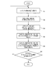
図2は、製品の製造時に、レンズシフト機構26により、投射レンズ24の位置を変更させた際のホワイトバランスの調整値を記憶部15に記憶させる手順を示すフローチャートである。この図2を参照して、プロジェクター1の製造工程においてレンズシフトの位置に関連付けてホワイトバランスの調整値を記憶部15に記憶する手順について説明する。
まず、作業者の操作に基づいて、制御部10は、投射光学系駆動部34を制御して、レンズシフト機構26を駆動させ、レンズシフトを特定の位置、例えば中央、に合わせる(ステップS1)。続いて、作業者の操作に基づいて、制御部10は、発光制御部18の機能により、青色光20a、赤色光20b、緑色光20cが各々最大出力値で出力されるようにレーザー光源42,43を制御する。これにより、スクリーンSCには、ホワイトバランス調整前の白画面が投射される(ステップs2)。なお、青色光20a、赤色光20b、緑色光20cを各々最大値で出力した調整前の白画面では、ホワイトバランスが適正に調整されていないため、正確な白色が再現されていない。
Next, the procedure for storing the detected value of the
FIG. 2 is a flowchart showing a procedure for storing the white balance adjustment value in the
First, based on the operator's operation, the
次に、制御部10は、発光制御部18の機能により、プロジェクター1の外部に設けられた外部センサーで測定する投射画像のRGB比が100:100:100となるように、レーザー光源42,43の発光量を調整する(ステップS3)。外部センサーで測定する投射画像のRGB比が100:100:100となるときは、プロジェクター1のホワイトバランスが適正に調整され、スクリーンSCに正確な白色が再現されているときである。
次に、制御部10は、調整値取得部38の機能により、外部センサーで測定する投射画像のRGB比が100:100:100となったときの、プロジェクター1内部のカラーセンサー14の検出値を取得する(ステップS4)。これにより、カラーセンサー14では、レンズシフトの位置が特定の位置となった場合に、プロジェクター1のホワイトバランスが適正となる変調光28のR:G:Bの光量比が検出される。
続いて、調整値取得部38は、レンズシフトの位置と、カラーセンサー14の検出値とを関連付けて、ホワイトバランスの調整値として記憶部15に記憶する(ステップS5)。
Next, the
Next, the
Subsequently, the adjustment
ホワイトバランスの調整値と関連付けて記憶部15に記憶するレンズシフトの位置は、任意に設定可能である。例えばレンズシフトの中央と上下左右の最大位置との5つのポイントについて、レンズシフトの位置と、ホワイトバランスが適正となるカラーセンサー14の検出値と、を関連付けてホワイトバランスの調整値として記憶しておく構成としても良い。
作業者は、予め設定した全てのポイントについて、ホワイトバランスの調整値が記憶部15に記憶されたかを判断し(ステップS6)、他に調整値が記録されるべきレンズシフトの位置が残っている場合には(ステップS6:No)、当該位置についてステップS1〜S5を繰り返す。予め設定した全てのポイントについてホワイトバランスの調整値が記録されたと判断した場合には(ステップS6:Yes)、作業者は、レンズシフトに関するホワイトバランスの調整値を記憶部15に記憶させる作業を終了する。
The position of the lens shift stored in the
The operator determines whether or not the white balance adjustment value is stored in the
図3は、製品の製造時に、ズーム機構27により、投射レンズ24のズームの状態を変更させた際のホワイトバランスの調整値を記憶部15に記憶させる手順を示すフローチャートである。この図3を参照して、プロジェクター1の製造工程において、投射レンズ24のズームの状態に関連付けてホワイトバランスの調整値を記憶部15に記憶する手順について説明する。
まず、作業者の操作に基づいて、制御部10は、投射光学系駆動部34を制御して、ズーム機構27を駆動させ、投射レンズ24のズームの状態を特定の状態、例えば中央、に合わせる(ステップS11)。続いて、作業者の操作に基づいて、制御部10は、発光制御部18の機能により、青色光20a、赤色光20b、緑色光20cが各々最大出力値で出力されるようにレーザー光源42,43を制御する。これにより、スクリーンSCには、ホワイトバランス調整前の白画面が投射される(ステップS12)。なお、青色光20a、赤色光20b、緑色光20cを各々最大出力値で出力した調整前の白画面では、ホワイトバランスが適正に調整されていないため、正確な白色が再現されていない。
FIG. 3 is a flowchart showing a procedure for storing the white balance adjustment value in the
First, based on the operator's operation, the
次に、制御部10は、発光制御部18の機能により、プロジェクター1の外部センサーで測定する投射画像のRGB比が100:100:100となるように、レーザー光源42,43の発光量を調整する(ステップS13)。外部センサーで測定する投射画像のRGB比が100:100:100となるときは、プロジェクター1のホワイトバランスが適正に調整され、スクリーンSCに正確な白色が再現されているときである。
次に、制御部10は、調整値取得部38の機能により、外部センサーで測定する投射画像のRGB比が100:100:100となったときに、プロジェクター1の内部のカラーセンサー14で検出される検出値を取得する(ステップS14)。これにより、カラーセンサー14では、投射レンズ24のズームの状態が特定の状態となった場合に、プロジェクター1のホワイトバランスが適正となる変調光28のR:G:Bの光量比が検出される。
続いて、調整値取得部38は、ズームの状態と、カラーセンサー14の検出値とを関連付けて、ホワイトバランスの調整値として記憶部15に記憶する(ステップS15)。
Next, the
Next, when the RGB ratio of the projection image measured by the external sensor becomes 100: 100: 100 by the function of the adjustment
Subsequently, the adjustment
ホワイトバランスの調整値を記憶部15に記憶するズームの状態は、任意に設定可能である。例えばズームの中央とテレ、及び、ワイドの最大位置との3つのポイントについて、ズームの状態と、ホワイトバランスが適正となるカラーセンサー14の検出値と、を関連付けてホワイトバランスの調整値として記憶しておく構成としても良い。
作業者は、予め設定した全てのポイントについて、ホワイトバランスの調整値が記憶部15に記憶されたかを判断し(ステップS16)、他に調整値が記録されるべきズームの状態が残っている場合には(ステップS16:No)、当該状態についてステップS11〜S15を繰り返す。予め設定した全てのポイントについてホワイトバランスの調整値が記録されたと判断した場合には(ステップS16:Yes)、作業者は、ズームの状態に関するホワイトバランスの調整値を記憶部15に記憶させる作業を終了する。
The zoom state in which the white balance adjustment value is stored in the
The operator determines whether or not the white balance adjustment value has been stored in the
図4は、製品の製造時に、絞り機構25により、投射レンズ24の絞りの状態を変更させた際のホワイトバランスの調整値を記憶部15に記憶させる手順を示すフローチャートである。この図4を参照して、プロジェクター1の製造工程において、投射レンズ24の絞りの状態に関連付けてホワイトバランスの調整値を記憶部15に記憶する手順について説明する。
まず、作業者の操作に基づいて、制御部10は、投射光学系駆動部34を制御して、絞り機構25を駆動させ、投射レンズ24の絞りの状態を特定の状態、例えば中央、に合わせる(ステップS21)。続いて、作業者の操作に基づいて、制御部10は、発光制御部18の機能により、青色光20a、赤色光20b、緑色光20cが各々最大出力値で出力されるようにレーザー光源42,43を制御する。これにより、スクリーンSCには、ホワイトバランス調整前の白画面が投射される(ステップS22)。なお、青色光20a、赤色光20b、緑色光20cを各々最大出力値で出力した調整前の白画面では、ホワイトバランスが適正に調整されていないため、正確な白色が再現されていない。
FIG. 4 is a flowchart illustrating a procedure for storing the white balance adjustment value in the
First, based on the operator's operation, the
次に、制御部10は、発光制御部18の機能により、プロジェクター1の外部に設けられた外部センサーで測定する投射画像のRGB比が100:100:100となるように、レーザー光源42,43の発光量を調整する(ステップS23)。外部センサーで測定する投射画像のRGB比が100:100:100となるときは、プロジェクター1のホワイトバランスが適正に調整され、スクリーンSCに正確な白色が再現されているときである。
次に、制御部10は、調整値取得部38の機能により、外部センサーで測定する投射画像のRGB比が100:100:100となったときに、プロジェクター1の内部のカラーセンサー14で検出される検出値を取得する(ステップS24)。これにより、カラーセンサー14では、投射レンズ24の絞りの状態が特定の状態となった場合に、プロジェクター1のホワイトバランスが適正となる変調光28のR:G:Bの光量比が検出される。
続いて、調整値取得部38は、絞りの状態と、カラーセンサー14の検出値とを関連付けて、ホワイトバランスの調整値として記憶部15に記憶する(ステップS25)。
Next, the
Next, when the RGB ratio of the projection image measured by the external sensor becomes 100: 100: 100 by the function of the adjustment
Subsequently, the adjustment
ホワイトバランスの調整値を記憶部15に記憶する絞りの状態は、任意に設定可能である。例えば絞りの中央と全閉、及び、全開の最大位置との3つのポイントについて、絞りの状態と、ホワイトバランスが適正となるカラーセンサー14の検出値と、を関連付けてホワイトバランスの調整値として記憶しておく構成としても良い。
作業者は、予め設定した全てのポイントについて、ホワイトバランスの調整値が記憶部15に記憶されたかを判断し(ステップS26)、他に調整値が記録されるべき絞りの状態が残っている場合には(ステップS26:No)、当該状態についてステップS21〜S25を繰り返す。予め設定した全てのポイントについてホワイトバランスの調整値が記録されたと判断した場合には(ステップS26:Yes)、作業者は、絞りの状態に関するホワイトバランスの調整値を記憶部15に記憶させる作業を終了する。
The aperture state for storing the white balance adjustment value in the
The operator determines whether white balance adjustment values have been stored in the
上述したように、プロジェクター1の記憶部15には、投射光学系23が特定の状態となった場合に、投射画像のホワイトバランスが適正となるカラーセンサー14で検出される変調光28のR:G:Bの光量比が、複数の投射光学系23の状態について其々予め記憶されている。プロジェクター1は、起動時に、レンズシフトの位置、ズームの状態、及び、絞りの状態等の投射光学系23の状態を判断し、投射光学系23の状態と、記憶部15に記憶されている投射光学系23の特定の状態でのホワイトバランスの調整値と、に基づいて、ホワイトバランスを調整することができる。
次に、投射光学系23の特定の状態に基づいてホワイトバランスを調整する際のプロジェクター1の動作について図5のフローチャートを用いて説明する。
As described above, in the
Next, the operation of the projector 1 when adjusting the white balance based on the specific state of the projection
まず、プロジェクター1の起動時、または、ユーザー操作により投射光学系23の状態が変更されたことを検出した際には、制御部10は、投射光学系駆動部34から投射光学系23の状態を検出する(ステップS31)。次に、制御部10は、ステップS31で検出された状態が記憶部15にホワイトバランスの調整値が予め記憶されている特定の状態か否かを判定する(ステップS32)。投射光学系23の状態が、記憶部15にホワイトバランスの調整値が予め記憶されている特定の状態であると判定した場合(ステップS32:Yes)、制御部10は、調整値取得部38の機能により、記憶部15からステップS31で検出された特定の状態に関連付けられて記憶されている調整値を取得する(ステップS33)。
投射光学系23の状態が、記憶部15にホワイトバランスの調整値が予め記憶されている特定の状態ではないと判定した場合(ステップS32:No)、制御部10は、調整値取得部38の機能により、記憶部15に記憶されている特定の状態と、特定の状態に関連付けられて記憶されている調整値と、からホワイトバランスを検出された状態に対して適切に調整するための推定値を算出する(ステップS34)。
First, when the projector 1 is started up or when it is detected that the state of the projection
When it is determined that the state of the projection
ここで、記憶部15に記憶されている特定の状態と、特定の状態に関連付けられて記憶されている調整値と、からホワイトバランスを検出された状態に対して適切に調整するための推定値を算出する方法の一例を説明する。
図6〜図8は、制御部10が検出する投射光学系23の状態を模式的に示す図であり、図6はレンズシフトの状態、図7はズームの状態、図8は絞りの状態を示す図である。
図6(A)に例示したように、レンズシフトの位置は、XY直交座表系で示される。図6(A)に示す図表のX軸は水平方向すなわちプロジェクター1の接地面に水平な方向におけるレンズシフト位置を示し、Y軸は垂直方向におけるレンズシフト位置を示す。また、原点(0,0)はレンズシフトの調整範囲の下限を示し左上に相当する位置に設定され、X軸方向における調整範囲の最大値を100、Y軸方向における調整範囲の最大値を100として表す。
本実施形態では、図6(A)の例で中央に相当する位置A(50,50)、真中上に相当する位置B(50,0)、真中下に相当する位置C(50,100)、真中左に相当する位置D(0,50)、および、真中右に相当する位置E(100,50)の各位置を、特定のレンズシフト位置とする。記憶部15には、これら位置A〜Eの各々の位置に対応づけて、ホワイトバランスの調整値が記憶されている。調整値取得部38は、制御部10により検出されたレンズシフトの位置が、これらの特定の位置A〜Eのいずれにも該当しないと判定された場合には、検出されたレンズシフトの位置に対応するホワイトバランスを調整するための推定値を、記憶部15に記憶された特定の位置A〜Eと、これらの特定の位置に対応する調整値とに基づいて直線補間、2次関数補間、またはスプライン補間等の補間方法を用いて算出する。
例えば、制御部10により検出されたレンズシフトの位置が図6(A)の位置F(75,50)のとき、調整値取得部38は、中央A(50,50)及び真中右E(100,50)の各位置の調整値に基づいて位置Fに対してホワイトバランスを調整するための推定値を算出する。中央A(50,50)に関連付けて記憶部15に記憶された調整値(R:G:B)が(98:97:100)であり、真中右E(100,50)に関連付けて記憶部15に記憶された調整値(R:G:B)が(85:92:90)である場合、位置F(75,50)に対してホワイトバランスを調整するための推定値(R:G:B)は、直線補間により以下のように算出される。
R=(98+85)÷2=91.5
G=(97+92)÷2=94.5
B=(100+90)÷2=95
Here, the estimated value for appropriately adjusting the white balance from the specific state stored in the
6 to 8 are diagrams schematically showing the state of the projection
As illustrated in FIG. 6A, the lens shift position is indicated by an XY orthogonal coordinate system. 6A shows the lens shift position in the horizontal direction, that is, the direction horizontal to the ground plane of the projector 1, and the Y axis shows the lens shift position in the vertical direction. The origin (0, 0) indicates the lower limit of the lens shift adjustment range and is set at a position corresponding to the upper left. The maximum value of the adjustment range in the X-axis direction is 100, and the maximum value of the adjustment range in the Y-axis direction is 100. Represent as
In the present embodiment, in the example of FIG. 6A, the position A (50, 50) corresponding to the center, the position B (50, 0) corresponding to the upper middle, and the position C (50, 100) corresponding to the lower middle. Each position of a position D (0, 50) corresponding to the middle left and a position E (100, 50) corresponding to the middle right is set as a specific lens shift position. The storage unit 1 5, in association with the respective positions of these positions A-E, white balance adjustment value is stored. When it is determined that the position of the lens shift detected by the
For example, when the position of the lens shift detected by the
R = (98 + 85) ÷ 2 = 91.5
G = (97 + 92) ÷ 2 = 94.5
B = (100 + 90) ÷ 2 = 95
また、レンズシフトの位置は、図6(B)に例示したように、中央に相当する位置(50,50)を特定のレンズシフト位置として、この特定の位置に対応づけて、ホワイトバランスの調整値が記憶されている構成であっても良い。そして、真中上に相当する位置(50,0)、真中下に相当する位置(50,100)、真中左に相当する位置(0,50)、および、真中右に相当する位置(100,50)の各位置について、中央に相当する位置からの調整値の変化量が、各位置に対応付けて記憶部15に記憶される。各レンズシフト位置での変化量は、例えば、中央に相当する位置での変化量を100%とした場合に、真中上に相当する位置での変化量が95%、真中下に相当する位置での変化量が100%、真中左に相当する位置での変化量が120%、および、真中右に相当する位置での変化量が110%と記憶される。調整値取得部38は、制御部10により検出されたレンズシフトの位置が、中央に相当する位置に該当しないと判定された場合には、検出されたレンズシフトの位置に対応するホワイトバランスを調整するための推定値を、記憶部15に記憶された中央に相当する位置に対応する調整値と、中央に相当する位置からの調整量の変化量とに基づいて直線補間、2次関数補間、またはスプライン補間等の補間方法を用いて算出する。
例えば、制御部10により検出されたレンズシフトの位置が、図6(B)に示したXY座標系の(75,25)のとき、調整値取得部38は、中央に相当する位置(50,50)の調整値と、中央と真中上との中間に相当する位置(50,25)での変化量と、中央と真中右との中間に相当する位置(75,50)での変化量と、に基づいてホワイトバランスを調整するための推定値を算出する。中央A(50,50)に関連付けて記憶部15に記憶された調整値(R:G:B)が(98:97:100)であり、真中上に関連付けて記憶部15に記憶された変化量が95%であり、真中右に関連付けて記憶部15に記憶された変化量が110%である場合、レンズシフト位置(75,25)に対してホワイトバランスを調整するための推定値(R:G:B)は、直線補間により以下のように算出される。
R=((100%+95%)÷2)×((100%+110%)÷2)×98=100.3275
G=((100%+95%)÷2)×((100%+110%)÷2)×97=99.30375
B=((100%+95%)÷2)×((100%+110%)÷2)×100=102.375
なお、本実施形態では、各色光の変化量を同じ変化量としたが、これに限らず、赤色光R、緑色光G、青色光B毎に異なる変化量を特定のレンズシフト位置に対応付けて記憶部15に記憶しておく構成であっても良い。この構成によれば、より適切にホワイトバランスを調整するための推定値を算出することができる。
Further, as illustrated in FIG. 6B, the position of the lens shift is adjusted by adjusting the white balance by using the position (50, 50) corresponding to the center as a specific lens shift position and corresponding to this specific position. A configuration in which values are stored may be used. Then, a position corresponding to the upper middle (50, 0), a position corresponding to the lower middle (50, 100), a position corresponding to the middle left (0, 50), and a position corresponding to the middle right (100, 50). ), The change amount of the adjustment value from the position corresponding to the center is stored in the
For example, when the position of the lens shift detected by the
R = ((100% + 95%) ÷ 2) × ((100% + 110%) ÷ 2) × 98 = 100.3275
G = ((100% + 95%) ÷ 2) × ((100% + 110%) ÷ 2) × 97 = 99.30375
B = ((100% + 95%) ÷ 2) × ((100% + 110%) ÷ 2) × 100 = 102.375
In this embodiment, the amount of change of each color light is the same amount of change. However, the present invention is not limited to this, and a different amount of change for each of the red light R, the green light G, and the blue light B is associated with a specific lens shift position. It may be configured to be stored in the
また、図7(A)の例では、ズームの状態すなわちズーム位置を、ズームの調整範囲のテレ端を0、ワイド端を100とした場合の相対値として示しており、例えばズームを中央位置に合わせた場合の値は50となる。なお、図示は省略したが、ズームの状態を座標で示す方法を採用することも可能である。
本実施形態では、例えば、ズーム位置がテレ端(位置0)、中央(位置50)、及び、ワイド端(位置100)にある状態を、それぞれ特定の状態とし、これらの特定の状態にホワイトバランスの調整値が関連付けられて、記憶部15に記憶されている構成とすることができる。そして、調整値取得部38は、制御部10により検出されたズームの状態が、これらの特定の状態ではないと判定された場合には、検出されたズームの状態に対応するホワイトバランスを調整するための推定値を、記憶部15に記憶された特定の状態と、この特定の状態での調整値とに基づいて直線補間、2次関数補間、またはスプライン補間等の補間方法を用いて算出する。例えば、制御部10により検出されたズームの状態が図7(A)の状態G(位置25)のとき、調整値取得部38は、中央及びテレ端の各状態の調整値に基づいて状態Gに対してホワイトバランスを調整するための推定値を算出する。ズーム中央に関連付けて記憶部15に記憶された調整値(R:G:B)が(98:97:100)であり、ズームテレに関連付けて記憶部15に記憶された調整値(R:G:B)が(85:92:90)である場合、ズームの状態が状態G(25)に対してホワイトバランスを調整するための推定値(R:G:B)は、直線補間により以下のように算出される。
R=(98+85)÷2=91.5
G=(97+92)÷2=94.5
B=(100+90)÷2=95
In the example of FIG. 7A, the zoom state, that is, the zoom position is shown as a relative value when the tele end of the zoom adjustment range is 0 and the wide end is 100. For example, the zoom is at the center position. The combined value is 50. Although illustration is omitted, it is also possible to adopt a method of indicating the zoom state with coordinates.
In the present embodiment, for example, a state where the zoom position is at the tele end (position 0), the center (position 50), and the wide end (position 100) is set as a specific state, and white balance is set in these specific states. These adjustment values are associated with each other and stored in the
R = (98 + 85) ÷ 2 = 91.5
G = (97 + 92) ÷ 2 = 94.5
B = (100 + 90) ÷ 2 = 95
ズームの状態は、図7(B)に示したように、ズームを中央に合わせた状態を特定の状態として、この特定の状態に対応づけて、ホワイトバランスの調整値が記憶されている構成であっても良い。そして、テレ端、及び、ワイド端にズームを合わせた状態について、中央からの調整値の変化量が、各ズームの状態に対応付けて記憶部15に記憶される。各ズームの状態での変化量は、例えば、ズームを中央に合わせた状態での変化量を100%とした場合に、テレ端での変化量が90%、ワイド端での変化量が120%と記憶される。調整値取得部38は、制御部10により検出されたズームの状態が、中央に合わせた状態に相当する状態に該当しないと判定された場合には、検出されたズームの状態に対応するホワイトバランスを調整するための推定値を、記憶部15に記憶されたズームを中央に合わせた状態に対応する調整値と、中央からの調整量の変化量とに基づいて直線補間、2次関数補間、またはスプライン補間等の補間方法を用いて算出する。
例えば、制御部10により検出されたズームの状態がテレ端に合わせた状態の時、ホワイトバランスを調整するための推定値は、ズームの状態が中央に合わせた状態での調整値に対して90%となる。ズームを中央に合わせた状態に関連付けて記憶部15に記憶された調整値(R:G:B)が(98:97:100)であり、テレ端での中央に対する変化量が90%である場合、推定値は、以下のように算出される。
R=98×90%=88.2
G=97×90%=87.3
B=100×90%=90
なお、本実施形態では、各色光の変化量を同じ変化量としたが、これに限らず、赤色光R、緑色光G、青色光B毎に異なる変化量を特定のズームの状態に対応付けて記憶部15に記憶しておく構成であっても良い。この構成によれば、より適切にホワイトバランスを調整するための推定値を算出することができる。
As shown in FIG. 7B, the zoom state is a configuration in which the white balance adjustment value is stored in association with the specific state, with the zoom in the center. There may be. Then, with respect to the state where the zoom is adjusted to the tele end and the wide end, the amount of change in the adjustment value from the center is stored in the
For example, when the zoom state detected by the
R = 98 × 90% = 88.2
G = 97 × 90% = 87.3
B = 100 × 90% = 90
In the present embodiment, the amount of change of each color light is the same amount of change. However, the present invention is not limited to this, and a different amount of change for each of the red light R, green light G, and blue light B is associated with a specific zoom state. It may be configured to be stored in the
また、図8(A)の例では、レンズ絞りの状態すなわち絞りの調整位置を、全閉位置を0、全開位置を100とした場合の相対位置として示す。例えば、レンズ絞りを中央にした場合の値は50である。なお、図示は省略したが、レンズ絞りの状態を、座標で示す方法を採用することも可能である。
本実施形態では、例えば、絞りが全閉(位置0)、中央(位置50)、及び、全開(位置100)にある状態を、それぞれ特定の状態とし、これらの特定の状態にホワイトバランスの調整値が関連付けられて、記憶部15に記憶されている構成とすることができる。そして、調整値取得部38は、制御部10により検出されたレンズ絞りの状態が、これらの特定の状態ではないと判定された場合には、検出されたレンズ絞りの状態に対応するホワイトバランスを調整するための推定値を、記憶部15に記憶された特定の状態と、この特定の状態での調整値とに基づいて直線補間、2次関数補間、またはスプライン補間等の補間方法を用いて算出する。例えば、制御部10により検出されたレンズ絞りの状態が図8(A)の状態H(位置25)のとき、調整値取得部38は、レンズ絞り中央及びレンズ絞り全閉の各状態の調整値に基づいて状態Hに対してホワイトバランスを調整するための推定値を算出する。中央に関連付けて記憶部15に記憶された調整値(R:G:B)が(98:97:100)であり、全閉に関連付けて記憶部15に記憶された調整値(R:G:B)が(85:92:90)である場合、レンズ絞りの状態が状態H(25)に対してホワイトバランスを調整するための推定値(R:G:B)は、直線補間により以下のように算出される。
R=(98+85)÷2=91.5
G=(97+92)÷2=94.5
B=(100+90)÷2=95
In the example of FIG. 8A, the lens aperture state, that is, the aperture adjustment position, is shown as a relative position where the fully closed position is 0 and the fully open position is 100. For example, the value when the lens aperture is in the center is 50. Although illustration is omitted, it is also possible to adopt a method of indicating the state of the lens aperture with coordinates.
In the present embodiment, for example, the states in which the aperture is fully closed (position 0), the center (position 50), and the fully open (position 100) are set as specific states, and the white balance is adjusted to these specific states. A configuration in which values are associated and stored in the
R = (98 + 85) ÷ 2 = 91.5
G = (97 + 92) ÷ 2 = 94.5
B = (100 + 90) ÷ 2 = 95
レンズ絞りの状態は、図8(B)に示したように、レンズ絞りを中央に合わせた状態を特定の状態として、この特定の状態に対応づけて、ホワイトバランスの調整値が記憶されている構成であっても良い。そして、レンズ絞りの状態が全閉、及び、全開について、中央からの調整値の変化量が、各レンズ絞りの状態に対応付けて記憶部15に記憶される。各レンズ絞りの状態での変化量は、例えば、レンズ絞りを中央に合わせた状態での変化量を100%とした場合に、全閉での変化量が110%、全開での変化量が105%と記憶される。調整値取得部38は、制御部10により検出されたレンズ絞りの状態が、中央に合わせた状態に相当する状態に該当しないと判定された場合には、検出されたレンズ絞りの状態に対応するホワイトバランスを調整するための推定値を、記憶部15に記憶されたレンズ絞りを中央に合わせた状態に対応する調整値と、中央からの調整量の変化量とに基づいて直線補間、2次関数補間、またはスプライン補間等の補間方法を用いて算出する。
例えば、制御部10により検出されたレンズ絞りの状態が全閉の時、ホワイトバランスを調整するための推定値は、レンズ絞りの状態が中央に合わせた状態での調整値に対して110%となる。レンズ絞りを中央に合わせた状態に関連付けて記憶部15に記憶された調整値(R:G:B)が(98:97:100)であり、全閉での中央に対する変化量が110%である場合、推定値は、以下のように算出される。
R=98×110%=107.8
G=97×110%=106.7
B=100×110%=110
なお、本実施形態では、各色光の変化量を同じ変化量としたが、これに限らず、赤色光R、緑色光G、青色光B毎に異なる変化量を特定のレンズ絞りの状態に対応付けて記憶部15に記憶しておく構成であっても良い。この構成によれば、より適切にホワイトバランスを調整するための推定値を算出することができる。
As shown in FIG. 8B, the lens aperture state is stored in a state where the lens aperture is set at the center, and the white balance adjustment value is stored in association with the specific state. It may be a configuration. When the lens aperture state is fully closed and fully open, the amount of change in the adjustment value from the center is stored in the
For example, when the lens aperture state detected by the
R = 98 × 110% = 107.8
G = 97 × 110% = 106.7
B = 100 × 110% = 110
In the present embodiment, the amount of change of each color light is the same amount of change. However, the present invention is not limited to this, and a different amount of change for each of the red light R, green light G, and blue light B corresponds to the state of a specific lens aperture. In addition, the
このように、制御部10は、調整値取得部38の機能により投射光学系23の状態に対応するホワイトバランスの調整値または推定値を取得または算出した後、続いて、発光制御部18を制御し、カラーセンサー14の検出値が、調整値取得部38により取得または算出された調整値または推定値と合うように、レーザー光源42,43の発光量を調整する(ステップS35)。つまり、制御部10は、PWM信号生成部50の機能によりレーザー光源42,43の発光量をパルス制御して、青色光20a、赤色光20b、緑色光20cの出力値を変更し、変調光28のR:G:Bの光量比をプロジェクター1のホワイトバランスが適正となる光量比とする。
As described above, the
この構成によれば、投射光学系23の状態に応じて、プロジェクター1のホワイトバランスが適正となるように変調光28のR:G:Bの光量比を変更することができる。また、投射光学系23から投射される変調光28のR:G:Bの光量比を調整してホワイトバランスの適正化を行うため、光学系の状態やレーザー光源の経年変化に伴ってホワイトバランスが複雑に変化する場合であっても、適切な調整を行うことができ、高品位の画像を投射することができる。
According to this configuration, the R: G: B light quantity ratio of the modulated light 28 can be changed according to the state of the projection
以上説明したように、本発明を適用した実施形態に係るプロジェクター1によれば、複数のレーザー光源42,43と、複数のレーザー光源42,43が発する光を変調する光変調装置22と、を備え、光変調装置22で変調された変調光を投射する投射部20と、投射部20から投射される変調光28の投射状態を光学的に変化させる投射光学系23と、投射光学系23の状態を変化させる投射光学系駆動部34と、投射光学系23の状態と、変調光28のホワイトバランスを整えるための各々のレーザー光源42,43の発光量の調整値と、を関連付けて記憶する記憶部15と、投射光学系23の状態に対応した調整値に基づいて各々のレーザー光源42,43の発光量を調整するPWM信号生成部50と、を備えた。これにより、投射光学系23の状態変化によりホワイトバランスが変化しても、記憶部15に予め記憶している調整値に基づいてレーザー光源42,43の発光量を調整することにより、変調光28のホワイトバランスを適切に、かつ速やかに調整することができる。
As described above, according to the projector 1 according to the embodiment to which the present invention is applied, the plurality of
また、プロジェクター1は、記憶部15は、投射光学系23の特定の状態と、調整値とを関連付けて記憶し、投射光学系駆動部34により投射光学系23が特定の状態とされた場合に、記憶部15に記憶された調整値に基づいてPWM信号生成部50によりレーザー光源42,43の発光量を調整し、投射光学系駆動部34により投射光学系23が特定の状態以外の状態とされた場合には、記憶部15に記憶された調整値から算出される推定値に基づいてPWM信号生成部50によりレーザー光源42,43の発光量を調整する発光制御部18をさらに備えた。これにより、投射光学系23の状態変化に伴ってホワイトバランスが変化しても速やかに調整することができる。また、ホワイトバランスの調整値が少なくても様々な状態で調整を行うことができ、多数の調整値を必要としないので調整値の取得に要する時間を短縮できる。
In the projector 1, the
また、プロジェクター1は、投射光学系23が特定の状態となった場合において変調光28のホワイトバランスを整える調整値を取得し、投射光学系23の状態と調整値とを関連付けて記憶部に記憶する調整値取得部38をさらに備えた。これにより、投射光学系23の状態と、その状態でのホワイトバランスの調整値とを関連づけて記憶させておくことができるため、実際に調整値を検出する回数を抑えることができる。
Further, the projector 1 acquires an adjustment value for adjusting the white balance of the modulated
また、プロジェクター1は、いずれかのレーザー光源42,43の光から色変換及び/又は分光により複数の色光を生成する蛍光体ホイール45及び分光部46と、蛍光体ホイール45及び分光部46により生成された複数の色光を変調する光変調装置22と、をさらに備え、発光制御部18は、投射光学系23の状態に基づいて、記憶部15に記憶された調整値または記憶部15に記憶された調整値から算出される推定値から、各々の色光の光量の調整量を求め、さらに各々のレーザー光源42,43の調整量を求めてPWM信号生成部50によりレーザー光源42,43の発光量を調整する。これにより、色変換及び/又は分光により1つのレーザー光源43から複数の色を生成する構成において、投射光学系23の状態の変化に伴ってホワイトバランスが変化しても、変調光28のホワイトバランスを適切に、かつ速やかに調整できる。
Further, the projector 1 is generated by the
また、プロジェクター1は、投射光学系23は、投射レンズ24を移動させるレンズシフト機構26を備え、投射光学系駆動部34はレンズシフト機構26により投射レンズ24の位置を変更させるものであり、調整値取得部38は、投射光学系23の投射レンズ24の位置が特定の位置となった場合において複数のレーザー光源42,43が発する光を合成した変調光28のホワイトバランスを整える調整値を取得する。これにより、投射レンズ24の位置が変更することにより、例えば各レーザー光源42,43からの光路長の差に起因してホワイトバランスが変化しても、ホワイトバランスを適切に、かつ速やかに調整できる。
In the projector 1, the projection
また、プロジェクター1は、変調光28のホワイトバランスを検出するカラーセンサー14と、投射光学系23が特定の状態となった場合の変調光28のホワイトバランスをカラーセンサー14により検出し、その検出値を保持する記憶部15と、を備え、調整値取得部38は、記憶部15により保持された検出値から調整値を取得する。これにより、実際の検出値に基づいてホワイトバランスを適切に調整することができ、かつ、代表的な検出値から得られる調整値を演算して、別の調整値を取得できるので、実際に検出する回数を抑えることができる。
Further, the projector 1 detects the white balance of the
また、プロジェクター1は、調整値取得部38は、変調光28をプロジェクター1の外部で測定した測定値と、カラーセンサー14により検出された検出値とに基づいて、調整値を取得する。これにより、プロジェクター1のホワイトバランスを、プロジェクター1の外部で測定した測定値を用いて調整することにより、より正確にホワイトバランスを調整きる。また投射光学系23の状態変化に対応して多数回の検出を行うことなく、ホワイトバランスを調整できるので、調整に要する手間と時間の増加を避けることができる。
In the projector 1, the adjustment
なお、上記各実施形態は本発明を適用した具体的態様の例に過ぎず、本発明を限定するものではなく、上記実施形態とは異なる態様として本発明を適用することも可能である。
図1に示したプロジェクター1の各機能部は、ハードウェアとソフトウェアとの協働により実現される機能的構成を含み、その具体的な実装形態は特に制限されない。その他、プロジェクター1の各部の具体的な細部構成についても、本発明の趣旨を逸脱しない範囲で任意に変更可能である。
また、本実施形態のプロジェクター1は、青色光(B)を変調する液晶パネル22a、赤色光(R)を変調する液晶パネル22b、及び、緑色光(G)を変調する液晶パネル22cを備えた液晶プロジェクターである構成としたが、これに限らず、デジタルミラーデバイス(DMD)を用いたプロジェクターであってもよい。
また、本実施形態では、変調光28のホワイトバランスを正確な白、つまり、R:G:Bが100:100:100となるように調整する構成としたが、これに限らず、投射画面を青みがかった画面や赤みがかった画面に設定すべく、変調光の色光のバランスは、任意の色に設定可能である構成としても良い。
また、本実施形態では、投射光学系23の状態を変更する例として、レンズシフトの位置、ズームの状態、及び、レンズ絞りの状態を変更する場合について説明したが、光路上の光学部品、例えばシネマフィルターやアナモフィックレンズ、の状態を変更する場合や、照明絞りの状態を変更する等、ホワイトバランスに影響を与える設定の変更が行われた際に、ホワイトバランスを適切に調整する構成としても良い。
Each of the above embodiments is merely an example of a specific aspect to which the present invention is applied, and the present invention is not limited thereto. The present invention can be applied as a different aspect from the above embodiment.
Each functional unit of the projector 1 illustrated in FIG. 1 includes a functional configuration realized by cooperation of hardware and software, and the specific implementation is not particularly limited. In addition, the specific detailed configuration of each part of the projector 1 can be arbitrarily changed without departing from the gist of the present invention.
The projector 1 according to the present embodiment includes a
In the present embodiment, the white balance of the modulated
In this embodiment, as an example of changing the state of the projection
また、プロジェクター1が備えるカラーモード設定に応じて、バランス調整する色を変えてもよい。例えばカラーモード設定がダイナミックの場合は、本実施形態のように変調光28が白になるようにバランスを調整し、カラーモード設定がシネマモードの場合は、変調光28が青みがかった色になるようにバランスを調整してもよい。
また、投射環境に応じて最適な色になるように変調光28のバランスを調整してもよい。この場合、プロジェクター1は環境光を測定する照度センサーまたはカメラを備え、測定した環境光に応じて適切な色になるように変調光28のバランスを調整すればよい。
Further, the color for balance adjustment may be changed according to the color mode setting provided in the projector 1. For example, when the color mode setting is dynamic, the balance is adjusted so that the modulated
Further, the balance of the modulated
1…プロジェクター、10…制御部、12…映像入力部、14…カラーセンサー(検出手段)、15…記憶部(記憶手段、検出値保持手段)、17…投射制御部、18…発光制御部(制御手段)、20…投射部、21…光源部、22…光変調装置(変調手段)、23…投射光学系(光学系)、24…投射レンズ(光学部品)、25…絞り機構、26…レンズシフト機構、27…ズーム機構、28…変調光、34…投射光学系駆動部(光学系調整手段)、38…調整値取得部(調整値取得手段)、42…レーザー光源(光源)、45…蛍光体ホイール(色光変換手段)、46…分光部(色光変換手段)、50…PWM信号生成部(発光量調整手段)、SC…スクリーン。 DESCRIPTION OF SYMBOLS 1 ... Projector, 10 ... Control part, 12 ... Image | video input part, 14 ... Color sensor (detection means), 15 ... Memory | storage part (storage means, detection value holding means), 17 ... Projection control part, 18 ... Light emission control part ( Control means), 20 ... projection section, 21 ... light source section, 22 ... light modulation device (modulation means), 23 ... projection optical system (optical system), 24 ... projection lens (optical component), 25 ... stop mechanism, 26 ... Lens shift mechanism, 27 ... zoom mechanism, 28 ... modulated light, 34 ... projection optical system drive unit (optical system adjustment means), 38 ... adjustment value acquisition unit (adjustment value acquisition means), 42 ... laser light source (light source), 45 ... Phosphor wheel (color light converting means), 46... Spectroscopic section (color light converting means), 50... PWM signal generating section (light emission amount adjusting means), SC.
Claims (7)
前記複数の光源が発する複数の色光を変調する変調手段と、
前記変調手段で変調された変調光を投射する投射部と、
前記投射部から投射される変調光の投射状態を光学的に変化させる光学系と、
前記光学系の状態を変化させる光学系調整手段と、
前記投射部から投射される変調光の状態を検出する検出手段と、
前記光学系の複数の状態について、前記光学系の状態と、前記変調光のホワイトバランスを整えるための各々の前記光源の発光量の調整値とを関連付けて記憶する記憶手段と、
前記光学系調整手段が調整した前記光学系の状態を検出し、検出した前記光学系の状態に対応する調整値を前記記憶手段に記憶された調整値をもとに得る調整値取得手段と、
前記検出手段が検出する変調光の状態と、前記調整値取得手段により得られる調整値とに基づいて各々の前記光源の発光量を調整する発光量調整手段と、を備え、
前記記憶手段に記憶される複数の調整値は、前記光学系の状態を前記複数の状態の各々に設定し、前記複数の光源が発する光を予め設定された割合で含む変調光を前記投射部により投射し、投射された変調光の状態を前記検出手段により検出して得られる検出値であり、投射された変調光に含まれる前記複数の色光の光量比を示す値であることを特徴とするプロジェクター。 Multiple light sources;
Modulation means for modulating a plurality of color lights emitted by the plurality of light sources;
A projection unit that projects the modulated light modulated by the modulation unit;
An optical system for optically changing the projection state of the modulated light projected from the projection unit;
An optical system adjusting means for changing the state of the optical system;
Detecting means for detecting a state of modulated light projected from the projection unit;
Storage means for associating and storing the state of the optical system and the adjustment value of the light emission amount of each of the light sources for adjusting the white balance of the modulated light for a plurality of states of the optical system;
An adjustment value acquisition unit that detects the state of the optical system adjusted by the optical system adjustment unit, and obtains an adjustment value corresponding to the detected state of the optical system based on the adjustment value stored in the storage unit;
A light emission amount adjusting unit that adjusts the light emission amount of each of the light sources based on the state of modulated light detected by the detection unit and the adjustment value obtained by the adjustment value acquiring unit ;
The plurality of adjustment values stored in the storage unit sets the state of the optical system to each of the plurality of states, and includes the modulated light including the light emitted from the plurality of light sources at a preset ratio. Is a detection value obtained by detecting the state of the projected modulated light by the detecting means, and a value indicating a light amount ratio of the plurality of color lights included in the projected modulated light. Projector.
前記調整値取得手段は、前記光学系調整手段により前記光学系が前記記憶手段に記憶された状態とされた場合に、前記記憶手段に記憶された前記調整値に基づいて前記発光量調整手段により前記光源の発光量を調整し、前記光学系調整手段により前記光学系が前記記憶手段に記憶された状態以外の状態とされた場合には、前記記憶手段に記憶された調整値から算出される推定値に基づいて前記発光量調整手段により前記光源の発光量を調整することを特徴とするプロジェクター。 The projector according to claim 1,
The adjustment value acquisition unit is configured to cause the light emission amount adjustment unit to perform the adjustment based on the adjustment value stored in the storage unit when the optical system is stored in the storage unit by the optical system adjustment unit. When the light emission amount of the light source is adjusted and the optical system is brought into a state other than the state stored in the storage unit by the optical system adjustment unit, it is calculated from the adjustment value stored in the storage unit. A projector characterized in that the light emission amount of the light source is adjusted by the light emission amount adjusting means based on an estimated value.
前記調整値取得手段は、前記光学系を前記複数の状態のいずれかの状態とし、前記複数の光源が発する光を予め設定された割合で含む変調光を前記投射部により投射し、投射された変調光の状態を前記検出手段により検出して、前記変調光のホワイトバランスを整える調整値を取得し、前記光学系の状態と前記調整値とを関連付けて前記記憶手段に記憶させることを特徴とするプロジェクター。 The projector according to claim 2,
The adjustment value acquisition unit projects the modulated light including the light emitted from the plurality of light sources at a preset ratio by the projection unit, with the optical system in any one of the plurality of states. the state of the modulated light is detected by the detecting means, and wherein the acquired adjustment value adjust the white balance of the modulated light, causes stored in the storage means in association with the adjustment value and the state of the optical system Projector.
いずれかの前記光源の光から色変換及び/又は分光により複数の色光を生成する色光変換手段を備え、
前記変調手段は、前記色光変換手段により生成された前記複数の色光を変調し、
前記調整値取得手段は、前記光学系の状態に基づいて、前記記憶手段に記憶された前記調整値または前記記憶手段に記憶された前記調整値から算出される推定値から、各々の前記色光の光量の調整量を求め、さらに各々の前記光源の調整量を求めて前記発光量調整手段により前記光源の発光量を調整することを特徴とするプロジェクター。 The projector according to claim 2 or 3,
Color light conversion means for generating a plurality of color lights from the light of any one of the light sources by color conversion and / or spectroscopy ,
It said modulation means modulating the plurality of colored light generated by the colored light conversion means,
The adjustment value acquisition means , based on the state of the optical system, from the adjustment value stored in the storage means or the estimated value calculated from the adjustment value stored in the storage means. A projector characterized in that an adjustment amount of a light amount is obtained, an adjustment amount of each light source is obtained, and an emission amount of the light source is adjusted by the emission amount adjusting means.
前記光学系は光学部品を移動させる機構を備え、
前記光学系調整手段は前記機構により前記光学部品の位置を変更して前記光学系の状態を変化させるものであり、
前記調整値取得手段は、検出した前記光学系の光学部品の位置が特定の位置となった場合において複数の前記光源が発する光を合成した合成光のホワイトバランスを整える調整値を取得することを特徴とするプロジェクター。 The projector according to claim 3 or 4,
The optical system includes a mechanism for moving an optical component,
The optical system adjustment means changes the state of the optical system by changing the position of the optical component by the mechanism,
The adjustment value acquisition means acquires an adjustment value for adjusting the white balance of the combined light obtained by combining the light emitted from the plurality of light sources when the detected position of the optical component of the optical system becomes a specific position. Projector featuring.
前記調整値取得手段は、前記変調光を前記プロジェクターの外部で測定した測定値と、前記検出手段により検出された検出値とに基づいて、前記調整値を取得することを特徴とするプロジェクター。 The projector according to any one of claims 1 to 5 ,
The adjustment value acquisition unit acquires the adjustment value based on a measurement value obtained by measuring the modulated light outside the projector and a detection value detected by the detection unit.
前記光学系調整手段が調整した前記光学系の状態を検出するステップと、
前記検出するステップで検出した前記光学系の状態に対応する調整値を前記記憶手段に記憶された調整値をもとに得るステップと、
前記投射部から投射される変調光の状態を検出するステップと
前記検出するステップで検出される変調光の状態と、前記記憶手段に記憶された調整値をもとに得られた調整値とに基づいて各々の前記光源の発光量を調整するステップとを有し、
前記記憶手段に記憶される複数の調整値は、前記光学系の状態を前記複数の状態の各々に設定し、前記複数の光源が発する光を予め設定された割合で含む変調光を前記投射部により投射し、投射された変調光の状態を前記検出手段により検出して得られる検出値であり、投射された変調光に含まれる前記複数の色光の光量比を示す値であることを特徴とするプロジェクターにおける発光制御方法。 A plurality of light sources, a modulation unit that modulates light emitted from the plurality of light sources, a projection unit that projects the modulated light modulated by the modulation unit, and a projection state of the modulated light projected from the projection unit optically An optical system that changes the state of the optical system, an optical system adjustment unit that changes the state of the optical system, a detection unit that detects a state of modulated light projected from the projection unit, and a plurality of states of the optical system A light emission control method in a projector, comprising: a storage unit that associates and stores a system state and an adjustment value of a light emission amount of each of the light sources for adjusting a white balance of the modulated light,
Detecting the state of the optical system adjusted by the optical system adjusting means;
Obtaining an adjustment value corresponding to the state of the optical system detected in the detecting step based on the adjustment value stored in the storage means;
Detecting a state of modulated light projected from the projection unit;
Yes and the state of the modulated light detected by said step of detecting, and adjusting the light emission amount of the light source of each on the basis of the adjustment value obtained based on the stored adjustment value in the storage means And
The plurality of adjustment values stored in the storage unit sets the state of the optical system to each of the plurality of states, and includes the modulated light including the light emitted from the plurality of light sources at a preset ratio. Is a detection value obtained by detecting the state of the projected modulated light by the detecting means, and a value indicating a light amount ratio of the plurality of color lights included in the projected modulated light. Control method for a projector to perform.
Priority Applications (3)
| Application Number | Priority Date | Filing Date | Title |
|---|---|---|---|
| JP2012158382A JP6047968B2 (en) | 2012-07-17 | 2012-07-17 | Projector and light emission control method in projector |
| CN201310261881.8A CN103543581B (en) | 2012-07-17 | 2013-06-27 | The light-emitting control method of projector and projector |
| US13/932,490 US9621863B2 (en) | 2012-07-17 | 2013-07-01 | Projector and light emission control method in the projector |
Applications Claiming Priority (1)
| Application Number | Priority Date | Filing Date | Title |
|---|---|---|---|
| JP2012158382A JP6047968B2 (en) | 2012-07-17 | 2012-07-17 | Projector and light emission control method in projector |
Publications (3)
| Publication Number | Publication Date |
|---|---|
| JP2014021227A JP2014021227A (en) | 2014-02-03 |
| JP2014021227A5 JP2014021227A5 (en) | 2015-08-27 |
| JP6047968B2 true JP6047968B2 (en) | 2016-12-21 |
Family
ID=49946287
Family Applications (1)
| Application Number | Title | Priority Date | Filing Date |
|---|---|---|---|
| JP2012158382A Expired - Fee Related JP6047968B2 (en) | 2012-07-17 | 2012-07-17 | Projector and light emission control method in projector |
Country Status (3)
| Country | Link |
|---|---|
| US (1) | US9621863B2 (en) |
| JP (1) | JP6047968B2 (en) |
| CN (1) | CN103543581B (en) |
Families Citing this family (9)
| Publication number | Priority date | Publication date | Assignee | Title |
|---|---|---|---|---|
| JP2015155958A (en) * | 2014-02-20 | 2015-08-27 | セイコーエプソン株式会社 | Illumination device and projector |
| JP6326999B2 (en) * | 2014-06-19 | 2018-05-23 | セイコーエプソン株式会社 | Display device and control method |
| JP6569243B2 (en) * | 2015-03-02 | 2019-09-04 | セイコーエプソン株式会社 | Light source device, projector, and color balance adjustment method |
| WO2017154125A1 (en) * | 2016-03-09 | 2017-09-14 | 三菱電機株式会社 | Synthetic-aperture-radar signal processing device |
| CN108632593B (en) * | 2018-05-31 | 2020-05-19 | 歌尔股份有限公司 | Method, device and equipment for correcting color convergence errors |
| CN108957931B (en) * | 2018-06-29 | 2020-11-03 | 海信视像科技股份有限公司 | White balance adjusting method of laser light source and laser projection equipment |
| JP2020060688A (en) * | 2018-10-10 | 2020-04-16 | ソニー株式会社 | Luminaire and display unit |
| US20220100069A1 (en) * | 2019-01-30 | 2022-03-31 | Sharp Nec Display Solutions, Ltd. | Chromaticity adjustment method and projector |
| JP2020184014A (en) | 2019-05-08 | 2020-11-12 | 株式会社リコー | Light source device, optical scanner, display system, and movable body |
Family Cites Families (31)
| Publication number | Priority date | Publication date | Assignee | Title |
|---|---|---|---|---|
| JPH07230069A (en) * | 1994-02-18 | 1995-08-29 | Toshiba Corp | Projection type display device |
| US5428408A (en) * | 1994-05-26 | 1995-06-27 | Philips Electronics North America Corporation | Color correction system for projection video system utilizing multiple light sources |
| JP2002350974A (en) | 2001-03-19 | 2002-12-04 | Sharp Corp | Projection type display device |
| JP2004184852A (en) | 2002-12-05 | 2004-07-02 | Olympus Corp | Display device, light source device and illuminator |
| JP4059271B2 (en) * | 2003-06-13 | 2008-03-12 | ソニー株式会社 | Projection display |
| JP2005156650A (en) | 2003-11-21 | 2005-06-16 | Hitachi Ltd | Projection-type video display device |
| US7095568B2 (en) * | 2003-12-19 | 2006-08-22 | Victor Company Of Japan, Limited | Image display apparatus |
| JP3972934B2 (en) | 2004-01-30 | 2007-09-05 | セイコーエプソン株式会社 | LIGHTING DEVICE, DISPLAY DEVICE, AND PROJECTION TYPE DISPLAY DEVICE |
| JP2006140839A (en) * | 2004-11-12 | 2006-06-01 | Sharp Corp | Projector |
| JP2006178080A (en) * | 2004-12-21 | 2006-07-06 | Olympus Corp | Projector |
| JP4893004B2 (en) * | 2005-03-24 | 2012-03-07 | セイコーエプソン株式会社 | projector |
| JP4981350B2 (en) * | 2006-04-27 | 2012-07-18 | キヤノン株式会社 | Image projection apparatus, image display system, control method for image projection apparatus, and control program |
| JP2007322945A (en) | 2006-06-03 | 2007-12-13 | Sony Corp | Display control device, display device, and display control method |
| JP2007328074A (en) * | 2006-06-07 | 2007-12-20 | Matsushita Electric Ind Co Ltd | Light source controller |
| JP2008026711A (en) * | 2006-07-24 | 2008-02-07 | Sanyo Electric Co Ltd | Display device |
| JP2008089836A (en) * | 2006-09-29 | 2008-04-17 | Seiko Epson Corp | Projector |
| JP2008233487A (en) | 2007-03-20 | 2008-10-02 | Matsushita Electric Ind Co Ltd | Light source controller |
| JP2008242126A (en) * | 2007-03-28 | 2008-10-09 | Seiko Epson Corp | Projector, image correction method, and image correction program |
| JP2009116208A (en) * | 2007-11-09 | 2009-05-28 | Panasonic Corp | Rear projection apparatus |
| JP5326271B2 (en) | 2007-12-13 | 2013-10-30 | セイコーエプソン株式会社 | Laser light source device, video display device |
| JP2009244809A (en) | 2008-03-31 | 2009-10-22 | Victor Co Of Japan Ltd | Image display apparatus |
| JP2009265135A (en) | 2008-04-22 | 2009-11-12 | Sharp Corp | Display device, panel, backlight, and method of controlling display device |
| JP5241356B2 (en) * | 2008-07-11 | 2013-07-17 | 三菱電機株式会社 | Projection type video equipment |
| JP5301923B2 (en) * | 2008-08-20 | 2013-09-25 | ローム株式会社 | Load driving device, lighting device, display device |
| US8608320B2 (en) * | 2009-03-26 | 2013-12-17 | Nec Display Solutions, Ltd. | Projector and method for controlling the same |
| JP2011030119A (en) * | 2009-07-29 | 2011-02-10 | Canon Inc | Image projection apparatus |
| JP5625287B2 (en) | 2009-08-21 | 2014-11-19 | カシオ計算機株式会社 | Light source device, projection device, projection method and program |
| JP5593703B2 (en) * | 2010-01-13 | 2014-09-24 | セイコーエプソン株式会社 | Projector and method for adjusting color balance of projected image in projector |
| JP5617288B2 (en) * | 2010-03-18 | 2014-11-05 | セイコーエプソン株式会社 | Lighting device and projector |
| JP2012014045A (en) * | 2010-07-02 | 2012-01-19 | Seiko Epson Corp | Projector |
| US8444275B2 (en) * | 2010-08-12 | 2013-05-21 | Eastman Kodak Company | Light source control for projector with multiple pulse-width modulated light sources |
-
2012
- 2012-07-17 JP JP2012158382A patent/JP6047968B2/en not_active Expired - Fee Related
-
2013
- 2013-06-27 CN CN201310261881.8A patent/CN103543581B/en active Active
- 2013-07-01 US US13/932,490 patent/US9621863B2/en active Active
Also Published As
| Publication number | Publication date |
|---|---|
| CN103543581A (en) | 2014-01-29 |
| CN103543581B (en) | 2015-11-18 |
| US20140022513A1 (en) | 2014-01-23 |
| US9621863B2 (en) | 2017-04-11 |
| JP2014021227A (en) | 2014-02-03 |
Similar Documents
| Publication | Publication Date | Title |
|---|---|---|
| JP6047968B2 (en) | Projector and light emission control method in projector | |
| JP6019859B2 (en) | Projector and light emission control method in projector | |
| US10341626B2 (en) | Image projection system, projector, and control method for image projection system | |
| US10638103B2 (en) | Image projection apparatus, control method of the image projection apparatus, and storage medium | |
| US10298920B2 (en) | Projector and method of controlling a projector | |
| JP6657987B2 (en) | Projector and projector control method | |
| US9578294B2 (en) | Projector and method for adjusting projector | |
| US11323673B2 (en) | Method for operating control apparatus, and projector | |
| JP2015018051A (en) | Image projection device and image display system | |
| JP2017129728A (en) | Image quality correcting method and image projecting system | |
| JP5822575B2 (en) | Image projection apparatus, control method for image projection apparatus, and program | |
| JP2017010057A (en) | Projector and projector light emission control method | |
| JP2014066805A (en) | Projector and emission control method in projector | |
| JP6665543B2 (en) | Projector and method of correcting captured image | |
| JP2011150111A (en) | Image processor, image display system, and image processing method | |
| JP6821914B2 (en) | Projector and projector control method | |
| JP6565224B2 (en) | Projector and projector control method | |
| US11483527B2 (en) | Method of operation of a control device configured to control a plurality of projectors and control device | |
| US20200296340A1 (en) | Color conversion method, color conversion device, and display device | |
| JP2016005221A (en) | Display device and control method | |
| JP2016161798A (en) | Projector and projector control method |
Legal Events
| Date | Code | Title | Description |
|---|---|---|---|
| A521 | Request for written amendment filed |
Free format text: JAPANESE INTERMEDIATE CODE: A523 Effective date: 20150709 |
|
| A621 | Written request for application examination |
Free format text: JAPANESE INTERMEDIATE CODE: A621 Effective date: 20150709 |
|
| A977 | Report on retrieval |
Free format text: JAPANESE INTERMEDIATE CODE: A971007 Effective date: 20160414 |
|
| A131 | Notification of reasons for refusal |
Free format text: JAPANESE INTERMEDIATE CODE: A131 Effective date: 20160426 |
|
| A521 | Request for written amendment filed |
Free format text: JAPANESE INTERMEDIATE CODE: A523 Effective date: 20160623 |
|
| TRDD | Decision of grant or rejection written | ||
| A01 | Written decision to grant a patent or to grant a registration (utility model) |
Free format text: JAPANESE INTERMEDIATE CODE: A01 Effective date: 20161025 |
|
| A61 | First payment of annual fees (during grant procedure) |
Free format text: JAPANESE INTERMEDIATE CODE: A61 Effective date: 20161107 |
|
| R150 | Certificate of patent or registration of utility model |
Ref document number: 6047968 Country of ref document: JP Free format text: JAPANESE INTERMEDIATE CODE: R150 |
|
| LAPS | Cancellation because of no payment of annual fees |