JP6045565B2 - Method and apparatus for estimating vehicle fuel consumption - Google Patents
Method and apparatus for estimating vehicle fuel consumption Download PDFInfo
- Publication number
- JP6045565B2 JP6045565B2 JP2014503219A JP2014503219A JP6045565B2 JP 6045565 B2 JP6045565 B2 JP 6045565B2 JP 2014503219 A JP2014503219 A JP 2014503219A JP 2014503219 A JP2014503219 A JP 2014503219A JP 6045565 B2 JP6045565 B2 JP 6045565B2
- Authority
- JP
- Japan
- Prior art keywords
- vehicle
- value
- engine
- fuel
- output
- Prior art date
- Legal status (The legal status is an assumption and is not a legal conclusion. Google has not performed a legal analysis and makes no representation as to the accuracy of the status listed.)
- Expired - Fee Related
Links
Images


Classifications
-
- F—MECHANICAL ENGINEERING; LIGHTING; HEATING; WEAPONS; BLASTING
- F02—COMBUSTION ENGINES; HOT-GAS OR COMBUSTION-PRODUCT ENGINE PLANTS
- F02D—CONTROLLING COMBUSTION ENGINES
- F02D41/00—Electrical control of supply of combustible mixture or its constituents
- F02D41/02—Circuit arrangements for generating control signals
- F02D41/04—Introducing corrections for particular operating conditions
- F02D41/08—Introducing corrections for particular operating conditions for idling
- F02D41/086—Introducing corrections for particular operating conditions for idling taking into account the temperature of the engine
-
- G—PHYSICS
- G01—MEASURING; TESTING
- G01M—TESTING STATIC OR DYNAMIC BALANCE OF MACHINES OR STRUCTURES; TESTING OF STRUCTURES OR APPARATUS, NOT OTHERWISE PROVIDED FOR
- G01M9/00—Aerodynamic testing; Arrangements in or on wind tunnels
- G01M9/06—Measuring arrangements specially adapted for aerodynamic testing
-
- F—MECHANICAL ENGINEERING; LIGHTING; HEATING; WEAPONS; BLASTING
- F02—COMBUSTION ENGINES; HOT-GAS OR COMBUSTION-PRODUCT ENGINE PLANTS
- F02D—CONTROLLING COMBUSTION ENGINES
- F02D35/00—Controlling engines, dependent on conditions exterior or interior to engines, not otherwise provided for
- F02D35/02—Controlling engines, dependent on conditions exterior or interior to engines, not otherwise provided for on interior conditions
- F02D35/023—Controlling engines, dependent on conditions exterior or interior to engines, not otherwise provided for on interior conditions by determining the cylinder pressure
-
- B—PERFORMING OPERATIONS; TRANSPORTING
- B60—VEHICLES IN GENERAL
- B60R—VEHICLES, VEHICLE FITTINGS, OR VEHICLE PARTS, NOT OTHERWISE PROVIDED FOR
- B60R16/00—Electric or fluid circuits specially adapted for vehicles and not otherwise provided for; Arrangement of elements of electric or fluid circuits specially adapted for vehicles and not otherwise provided for
- B60R16/02—Electric or fluid circuits specially adapted for vehicles and not otherwise provided for; Arrangement of elements of electric or fluid circuits specially adapted for vehicles and not otherwise provided for electric constitutive elements
- B60R16/023—Electric or fluid circuits specially adapted for vehicles and not otherwise provided for; Arrangement of elements of electric or fluid circuits specially adapted for vehicles and not otherwise provided for electric constitutive elements for transmission of signals between vehicle parts or subsystems
- B60R16/0231—Circuits relating to the driving or the functioning of the vehicle
- B60R16/0236—Circuits relating to the driving or the functioning of the vehicle for economical driving
-
- B—PERFORMING OPERATIONS; TRANSPORTING
- B60—VEHICLES IN GENERAL
- B60T—VEHICLE BRAKE CONTROL SYSTEMS OR PARTS THEREOF; BRAKE CONTROL SYSTEMS OR PARTS THEREOF, IN GENERAL; ARRANGEMENT OF BRAKING ELEMENTS ON VEHICLES IN GENERAL; PORTABLE DEVICES FOR PREVENTING UNWANTED MOVEMENT OF VEHICLES; VEHICLE MODIFICATIONS TO FACILITATE COOLING OF BRAKES
- B60T8/00—Arrangements for adjusting wheel-braking force to meet varying vehicular or ground-surface conditions, e.g. limiting or varying distribution of braking force
- B60T8/17—Using electrical or electronic regulation means to control braking
- B60T8/172—Determining control parameters used in the regulation, e.g. by calculations involving measured or detected parameters
-
- F—MECHANICAL ENGINEERING; LIGHTING; HEATING; WEAPONS; BLASTING
- F02—COMBUSTION ENGINES; HOT-GAS OR COMBUSTION-PRODUCT ENGINE PLANTS
- F02D—CONTROLLING COMBUSTION ENGINES
- F02D19/00—Controlling engines characterised by their use of non-liquid fuels, pluralities of fuels, or non-fuel substances added to the combustible mixtures
- F02D19/06—Controlling engines characterised by their use of non-liquid fuels, pluralities of fuels, or non-fuel substances added to the combustible mixtures peculiar to engines working with pluralities of fuels, e.g. alternatively with light and heavy fuel oil, other than engines indifferent to the fuel consumed
- F02D19/08—Controlling engines characterised by their use of non-liquid fuels, pluralities of fuels, or non-fuel substances added to the combustible mixtures peculiar to engines working with pluralities of fuels, e.g. alternatively with light and heavy fuel oil, other than engines indifferent to the fuel consumed simultaneously using pluralities of fuels
- F02D19/082—Premixed fuels, i.e. emulsions or blends
- F02D19/085—Control based on the fuel type or composition
- F02D19/087—Control based on the fuel type or composition with determination of densities, viscosities, composition, concentration or mixture ratios of fuels
- F02D19/088—Control based on the fuel type or composition with determination of densities, viscosities, composition, concentration or mixture ratios of fuels by estimation, i.e. without using direct measurements of a corresponding sensor
-
- F—MECHANICAL ENGINEERING; LIGHTING; HEATING; WEAPONS; BLASTING
- F02—COMBUSTION ENGINES; HOT-GAS OR COMBUSTION-PRODUCT ENGINE PLANTS
- F02D—CONTROLLING COMBUSTION ENGINES
- F02D35/00—Controlling engines, dependent on conditions exterior or interior to engines, not otherwise provided for
- F02D35/02—Controlling engines, dependent on conditions exterior or interior to engines, not otherwise provided for on interior conditions
- F02D35/025—Controlling engines, dependent on conditions exterior or interior to engines, not otherwise provided for on interior conditions by determining temperatures inside the cylinder, e.g. combustion temperatures
-
- F—MECHANICAL ENGINEERING; LIGHTING; HEATING; WEAPONS; BLASTING
- F02—COMBUSTION ENGINES; HOT-GAS OR COMBUSTION-PRODUCT ENGINE PLANTS
- F02D—CONTROLLING COMBUSTION ENGINES
- F02D41/00—Electrical control of supply of combustible mixture or its constituents
- F02D41/02—Circuit arrangements for generating control signals
- F02D41/04—Introducing corrections for particular operating conditions
- F02D41/08—Introducing corrections for particular operating conditions for idling
-
- G—PHYSICS
- G01—MEASURING; TESTING
- G01F—MEASURING VOLUME, VOLUME FLOW, MASS FLOW OR LIQUID LEVEL; METERING BY VOLUME
- G01F9/00—Measuring volume flow relative to another variable, e.g. of liquid fuel for an engine
-
- G—PHYSICS
- G01—MEASURING; TESTING
- G01F—MEASURING VOLUME, VOLUME FLOW, MASS FLOW OR LIQUID LEVEL; METERING BY VOLUME
- G01F9/00—Measuring volume flow relative to another variable, e.g. of liquid fuel for an engine
- G01F9/001—Measuring volume flow relative to another variable, e.g. of liquid fuel for an engine with electric, electro-mechanic or electronic means
-
- G—PHYSICS
- G01—MEASURING; TESTING
- G01F—MEASURING VOLUME, VOLUME FLOW, MASS FLOW OR LIQUID LEVEL; METERING BY VOLUME
- G01F9/00—Measuring volume flow relative to another variable, e.g. of liquid fuel for an engine
- G01F9/02—Measuring volume flow relative to another variable, e.g. of liquid fuel for an engine wherein the other variable is the speed of a vehicle
- G01F9/023—Measuring volume flow relative to another variable, e.g. of liquid fuel for an engine wherein the other variable is the speed of a vehicle with electric, electro-mechanic or electronic means
-
- G—PHYSICS
- G01—MEASURING; TESTING
- G01G—WEIGHING
- G01G19/00—Weighing apparatus or methods adapted for special purposes not provided for in the preceding groups
- G01G19/08—Weighing apparatus or methods adapted for special purposes not provided for in the preceding groups for incorporation in vehicles
- G01G19/086—Weighing apparatus or methods adapted for special purposes not provided for in the preceding groups for incorporation in vehicles wherein the vehicle mass is dynamically estimated
-
- G—PHYSICS
- G01—MEASURING; TESTING
- G01M—TESTING STATIC OR DYNAMIC BALANCE OF MACHINES OR STRUCTURES; TESTING OF STRUCTURES OR APPARATUS, NOT OTHERWISE PROVIDED FOR
- G01M15/00—Testing of engines
-
- G—PHYSICS
- G01—MEASURING; TESTING
- G01M—TESTING STATIC OR DYNAMIC BALANCE OF MACHINES OR STRUCTURES; TESTING OF STRUCTURES OR APPARATUS, NOT OTHERWISE PROVIDED FOR
- G01M15/00—Testing of engines
- G01M15/02—Details or accessories of testing apparatus
-
- G—PHYSICS
- G01—MEASURING; TESTING
- G01M—TESTING STATIC OR DYNAMIC BALANCE OF MACHINES OR STRUCTURES; TESTING OF STRUCTURES OR APPARATUS, NOT OTHERWISE PROVIDED FOR
- G01M15/00—Testing of engines
- G01M15/04—Testing internal-combustion engines
-
- G—PHYSICS
- G01—MEASURING; TESTING
- G01M—TESTING STATIC OR DYNAMIC BALANCE OF MACHINES OR STRUCTURES; TESTING OF STRUCTURES OR APPARATUS, NOT OTHERWISE PROVIDED FOR
- G01M15/00—Testing of engines
- G01M15/04—Testing internal-combustion engines
- G01M15/042—Testing internal-combustion engines by monitoring a single specific parameter not covered by groups G01M15/06 - G01M15/12
- G01M15/048—Testing internal-combustion engines by monitoring a single specific parameter not covered by groups G01M15/06 - G01M15/12 by monitoring temperature
-
- G—PHYSICS
- G01—MEASURING; TESTING
- G01M—TESTING STATIC OR DYNAMIC BALANCE OF MACHINES OR STRUCTURES; TESTING OF STRUCTURES OR APPARATUS, NOT OTHERWISE PROVIDED FOR
- G01M15/00—Testing of engines
- G01M15/04—Testing internal-combustion engines
- G01M15/05—Testing internal-combustion engines by combined monitoring of two or more different engine parameters
-
- G—PHYSICS
- G01—MEASURING; TESTING
- G01M—TESTING STATIC OR DYNAMIC BALANCE OF MACHINES OR STRUCTURES; TESTING OF STRUCTURES OR APPARATUS, NOT OTHERWISE PROVIDED FOR
- G01M15/00—Testing of engines
- G01M15/04—Testing internal-combustion engines
- G01M15/09—Testing internal-combustion engines by monitoring pressure in fluid ducts, e.g. in lubrication or cooling parts
-
- G—PHYSICS
- G01—MEASURING; TESTING
- G01M—TESTING STATIC OR DYNAMIC BALANCE OF MACHINES OR STRUCTURES; TESTING OF STRUCTURES OR APPARATUS, NOT OTHERWISE PROVIDED FOR
- G01M15/00—Testing of engines
- G01M15/04—Testing internal-combustion engines
- G01M15/10—Testing internal-combustion engines by monitoring exhaust gases or combustion flame
- G01M15/102—Testing internal-combustion engines by monitoring exhaust gases or combustion flame by monitoring exhaust gases
- G01M15/104—Testing internal-combustion engines by monitoring exhaust gases or combustion flame by monitoring exhaust gases using oxygen or lambda-sensors
-
- G—PHYSICS
- G01—MEASURING; TESTING
- G01M—TESTING STATIC OR DYNAMIC BALANCE OF MACHINES OR STRUCTURES; TESTING OF STRUCTURES OR APPARATUS, NOT OTHERWISE PROVIDED FOR
- G01M17/00—Testing of vehicles
-
- G—PHYSICS
- G01—MEASURING; TESTING
- G01M—TESTING STATIC OR DYNAMIC BALANCE OF MACHINES OR STRUCTURES; TESTING OF STRUCTURES OR APPARATUS, NOT OTHERWISE PROVIDED FOR
- G01M17/00—Testing of vehicles
- G01M17/007—Wheeled or endless-tracked vehicles
-
- G—PHYSICS
- G07—CHECKING-DEVICES
- G07C—TIME OR ATTENDANCE REGISTERS; REGISTERING OR INDICATING THE WORKING OF MACHINES; GENERATING RANDOM NUMBERS; VOTING OR LOTTERY APPARATUS; ARRANGEMENTS, SYSTEMS OR APPARATUS FOR CHECKING NOT PROVIDED FOR ELSEWHERE
- G07C5/00—Registering or indicating the working of vehicles
- G07C5/004—Indicating the operating range of the engine
-
- G—PHYSICS
- G07—CHECKING-DEVICES
- G07C—TIME OR ATTENDANCE REGISTERS; REGISTERING OR INDICATING THE WORKING OF MACHINES; GENERATING RANDOM NUMBERS; VOTING OR LOTTERY APPARATUS; ARRANGEMENTS, SYSTEMS OR APPARATUS FOR CHECKING NOT PROVIDED FOR ELSEWHERE
- G07C5/00—Registering or indicating the working of vehicles
- G07C5/02—Registering or indicating driving, working, idle, or waiting time only
-
- G—PHYSICS
- G07—CHECKING-DEVICES
- G07C—TIME OR ATTENDANCE REGISTERS; REGISTERING OR INDICATING THE WORKING OF MACHINES; GENERATING RANDOM NUMBERS; VOTING OR LOTTERY APPARATUS; ARRANGEMENTS, SYSTEMS OR APPARATUS FOR CHECKING NOT PROVIDED FOR ELSEWHERE
- G07C5/00—Registering or indicating the working of vehicles
- G07C5/08—Registering or indicating performance data other than driving, working, idle, or waiting time, with or without registering driving, working, idle or waiting time
- G07C5/0808—Diagnosing performance data
-
- G—PHYSICS
- G07—CHECKING-DEVICES
- G07C—TIME OR ATTENDANCE REGISTERS; REGISTERING OR INDICATING THE WORKING OF MACHINES; GENERATING RANDOM NUMBERS; VOTING OR LOTTERY APPARATUS; ARRANGEMENTS, SYSTEMS OR APPARATUS FOR CHECKING NOT PROVIDED FOR ELSEWHERE
- G07C5/00—Registering or indicating the working of vehicles
- G07C5/08—Registering or indicating performance data other than driving, working, idle, or waiting time, with or without registering driving, working, idle or waiting time
- G07C5/0841—Registering performance data
- G07C5/085—Registering performance data using electronic data carriers
-
- F—MECHANICAL ENGINEERING; LIGHTING; HEATING; WEAPONS; BLASTING
- F02—COMBUSTION ENGINES; HOT-GAS OR COMBUSTION-PRODUCT ENGINE PLANTS
- F02D—CONTROLLING COMBUSTION ENGINES
- F02D41/00—Electrical control of supply of combustible mixture or its constituents
- F02D41/0025—Controlling engines characterised by use of non-liquid fuels, pluralities of fuels, or non-fuel substances added to the combustible mixtures
-
- Y—GENERAL TAGGING OF NEW TECHNOLOGICAL DEVELOPMENTS; GENERAL TAGGING OF CROSS-SECTIONAL TECHNOLOGIES SPANNING OVER SEVERAL SECTIONS OF THE IPC; TECHNICAL SUBJECTS COVERED BY FORMER USPC CROSS-REFERENCE ART COLLECTIONS [XRACs] AND DIGESTS
- Y02—TECHNOLOGIES OR APPLICATIONS FOR MITIGATION OR ADAPTATION AGAINST CLIMATE CHANGE
- Y02T—CLIMATE CHANGE MITIGATION TECHNOLOGIES RELATED TO TRANSPORTATION
- Y02T10/00—Road transport of goods or passengers
- Y02T10/80—Technologies aiming to reduce greenhouse gasses emissions common to all road transportation technologies
- Y02T10/84—Data processing systems or methods, management, administration
Landscapes
- Engineering & Computer Science (AREA)
- Physics & Mathematics (AREA)
- General Physics & Mathematics (AREA)
- Chemical & Material Sciences (AREA)
- Combustion & Propulsion (AREA)
- Mechanical Engineering (AREA)
- General Engineering & Computer Science (AREA)
- Fluid Mechanics (AREA)
- Automation & Control Theory (AREA)
- Oil, Petroleum & Natural Gas (AREA)
- Health & Medical Sciences (AREA)
- Emergency Medicine (AREA)
- Transportation (AREA)
- Combined Controls Of Internal Combustion Engines (AREA)
- Control Of Vehicle Engines Or Engines For Specific Uses (AREA)
- Testing Of Engines (AREA)
- Control Of Driving Devices And Active Controlling Of Vehicle (AREA)
- Electrical Control Of Air Or Fuel Supplied To Internal-Combustion Engine (AREA)
- Electric Propulsion And Braking For Vehicles (AREA)
Description
この発明は、車両のための車載診断を使用して車両の燃費を推定するための装置および方法に関する。 The present invention relates to an apparatus and method for estimating vehicle fuel consumption using in-vehicle diagnostics for vehicles.
特に、本発明は、車両の燃費の測定に関する。我々は、特定の陸上車の特性、ドライバー挙動の特性、および、旅程が進むにつれての旅程の特性の組み合わせに依存する、旅程の過程にわたる特定の車両およびドライバーの燃費および/または排出量の正確な推定を動的に与えるための装置および方法を含む、陸上車における燃費および/または排出量を推定する手段のための装置および方法について記載する。 In particular, the present invention relates to measurement of vehicle fuel consumption. We rely on specific ground vehicle characteristics, driver behavior characteristics, and a combination of itinerary characteristics as the itinerary progresses, to accurately measure the fuel consumption and / or emissions of a particular vehicle and driver over the itinerary process An apparatus and method for a means for estimating fuel consumption and / or emissions in land vehicles is described, including an apparatus and method for dynamically providing estimates.
我々の以前の特許および特許出願において、我々は、車両のエンジン管理システムから車載診断ポート(本明細書中で‘OBDポート’と称されるOBD、OBDII、CAN、および、同様のもの)を介して得られる信号を使用して陸上車(“車両”)における燃費および/または排出量を決定するための装置および方法について記載した。しばしば、必要とされるデータは、OBDポートから利用できずあるいは直ちに使用できる形態で利用できず、そのため、我々の特許出願(PCT第WO2008/146020号)において、我々は、燃費値および/または排出量値を決定するためにエンジン管理システムからの他の信号を特定して使用できる方法について記載する。そのような情報は、ドライバーモニタリングまたはトレーニングのために使用され得るドライバー挙動を推論するために使用することもできる。 In our previous patents and patent applications, we are going from the vehicle engine management system through the in-vehicle diagnostic port (OBD, OBDII, CAN, and the like referred to herein as 'OBD port') An apparatus and method for determining fuel economy and / or emissions in land vehicles (“vehicles”) using the resulting signals has been described. Often, the required data is not available from the OBD port or in ready-to-use form, so in our patent application (PCT No. WO2008 / 146020), we will calculate fuel economy values and / or emissions. A method is described that can be used to identify and use other signals from the engine management system to determine a quantity value. Such information can also be used to infer driver behavior that can be used for driver monitoring or training.
ある場合には、燃料/排出量計算を行なうために必要とされる何らかの情報を利用できない場合があるだけでなく、その情報が車両製造メーカーによって妨げられることさえあり得る。これらの場合、他の手法が必要とされる。 In some cases, not all information needed to perform fuel / emission calculations may be available, but that information may even be disturbed by the vehicle manufacturer. In these cases, other approaches are required.
旅程の過程にわたって瞬間ごとに車両の燃費の正確な予測にアクセスすることが有用であるのが分かる多くの事案および多くの車体がある。そのような予測は、必然的に、駆動されている特定の車両の特性およびドライバーの挙動の特性を旅程の過程にわたって反映する必要があり、また、これらの特性は、旅程の特性によって影響される。 There are many cases and many vehicle bodies that have proven useful to access accurate predictions of vehicle fuel economy from moment to moment throughout the itinerary process. Such predictions inevitably need to reflect the characteristics of the particular vehicle being driven and the characteristics of the driver's behavior over the course of the journey, and these characteristics are influenced by the characteristics of the itinerary .
燃費および排出量の推定を行なおうとする試みがなされてきたが、そのような試みは、瞬間ベースで利用される各車両、ドライバー、旅程の仕様ではなく、平均や一般性に基づく傾向がある。 Attempts have been made to estimate fuel consumption and emissions, but such attempts tend to be based on average and generality rather than on the specifications of each vehicle, driver, and itinerary used on an instantaneous basis .
例えばタクシー会社のオーナー、牽引機等の会社、および、保険会社においては、自分達のビジネスを最良に管理するために、車両、ドライバー挙動、および、旅程の特性に依存する燃費に関する正確な値を旅程の過程にわたって有することが有益である。 For example, taxi company owners, towing machine companies, and insurance companies, to manage their business best, have accurate fuel consumption values that depend on vehicle, driver behavior, and itinerary characteristics. It is beneficial to have it over the itinerary process.
本発明は、そのような正確な値を提供しようとする。 The present invention seeks to provide such an accurate value.
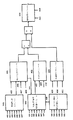
第1の態様によれば、本発明は、車両の燃費を推定する方法を含み、前記方法は、車両の車載診断システムから得られる少なくとも1つのパラメータを使用して、転がり出力成分、空気力学的抵抗成分、および、加速度成分を推定することによって、前記車両の全出力を推定するステップと、車両によって使用される燃料のタイプを決定するステップと、前記全出力の前記成分を加算して、前記燃料タイプのエネルギー値および所定のエンジン効率値で割ることによって、前記燃費を推定するステップとを含む。 According to a first aspect, the present invention includes a method for estimating fuel consumption of a vehicle, said method using at least one parameter obtained from an in-vehicle diagnostic system for the vehicle, the rolling output component, the aerodynamics Estimating the total output of the vehicle by estimating a resistance component and an acceleration component; determining a type of fuel used by the vehicle; adding the components of the total output; Estimating the fuel consumption by dividing by the fuel type energy value and a predetermined engine efficiency value.
好ましくは、転がり出力成分は、車両の質量の推定値を使用して推定され、および/または空気力学的抵抗は、車両の前面投影面積の推定値を使用して推定される。好ましくは、前記車両質量または前記前面投影面積を推定するステップは、少なくとも1つの動作パラメータがそのパラメータと関連付けられる値の所定の範囲内にある適格期間(qualifying period)を特定するステップを含む。好ましくは、前記車両質量を推定するステップは、適格期間中に取得される車両加速度読み取り値の加重平均値または移動平均値を決定するステップ、および/または適格期間中に取得される全出力読み取り値の加重平均値または移動平均値を決定するステップを含む。 Preferably, the rolling output component is estimated using an estimate of the vehicle's mass and / or the aerodynamic resistance is estimated using an estimate of the frontal projected area of the vehicle. Preferably, estimating the vehicle mass or the front projected area includes identifying a qualifying period in which at least one operating parameter is within a predetermined range of values associated with the parameter. Preferably, the step of estimating the vehicle mass comprises determining a weighted or moving average value of vehicle acceleration readings acquired during the qualifying period, and / or a total output reading acquired during the qualifying period. Determining a weighted average value or a moving average value.
好ましくは、車両質量を推定するための前記適格期間を特定するための前記動作パラメータのうちの1つが前記車両加速度から成り、および/または前面投影面積を推定するための前記適格期間を特定するための前記動作パラメータのうちの1つが前記車両加速度から成る。好ましくは、前記適格期間を特定するための基準は、前記車両加速度が所定の閾値を上回ることであり、前記閾値は、略ピーク加速度を特定するように選択され、および/または所定の閾値間にあり、前記閾値は、略定常状態動作の期間を特定するように選択される。好ましくは、前記方法は、少なくとも1つのOBDパラメータを使用して前記車両のためのエンジン負荷報告方策(engine load reporting strategy)を特定するステップを更に含む。 Preferably, one of the operating parameters for identifying the qualifying period for estimating vehicle mass comprises the vehicle acceleration and / or for identifying the qualifying period for estimating a front projection area One of the operating parameters comprises the vehicle acceleration. Preferably, the criterion for identifying the eligibility period is that the vehicle acceleration is above a predetermined threshold, the threshold being selected to identify a substantially peak acceleration and / or between the predetermined thresholds. Yes, the threshold is selected to specify a period of substantially steady state operation. Preferably, the method further comprises identifying an engine load reporting strategy for the vehicle using at least one OBD parameter.
好ましくは、前記エンジン負荷報告方策を特定するステップは、前記エンジン負荷および前記エンジン速度を得て、前記エンジン負荷を前記エンジン速度と関連付けられるエンジン負荷閾値と比較するステップを含む。好ましくは、エンジン負荷閾値は、前記エンジンがアイドリングしている期間を特定するように選択される。好ましくは、前記車両のクランクに与えられる力が、力とエンジンサイズとの間の実験的に導き出された関係を使用して推定される。 Preferably, identifying the engine load reporting strategy includes obtaining the engine load and the engine speed and comparing the engine load to an engine load threshold associated with the engine speed. Preferably, the engine load threshold is selected so as to specify a period during which the engine is idling. Preferably, the force applied to the crank of the vehicle is estimated using an experimentally derived relationship between force and engine size.
好ましくは、前記方法は、複数の想定し得るエンジン負荷報告方策のうちのいずれがエンジンを伴う車両の車載診断システムによって使用されるのかを見出すための方法を含み、この方法は、車載診断システムパラメータを検査するステップと、エンジンが動作しているときに、異なるエンジン負荷報告方策によりもたらされるエンジン負荷値同士の間の差をほぼ最大にするようにエンジン負荷を決定するステップとを含む。 Preferably, the method includes a method for finding out which of a plurality of possible engine load reporting strategies are used by an in-vehicle diagnostic system for a vehicle with an engine, the method comprising in-vehicle diagnostic system parameters And determining the engine load to approximately maximize the difference between engine load values caused by different engine load reporting strategies when the engine is operating.
好ましくは、前記方法は、異なるエンジン負荷報告方策によりもたらされるエンジン負荷値同士の間の差をほぼ最大にするように前記エンジンがアイドリングしている期間を特定するステップを更に含む。 Preferably, the method further comprises identifying a period of time during which the engine is idling so as to substantially maximize the difference between engine load values caused by different engine load reporting strategies.
好ましくは、前記エンジンがアイドリングしている期間は、前記車載診断システムパラメータを使用することによって、および/または前記エンジン速度とアイドリング速度閾値とを比較することによって特定される。 Preferably, the period of time that the engine is idling is determined by using the in-vehicle diagnostic system parameters and / or by comparing the engine speed to an idling speed threshold.
好ましくは、前記方法は、前記エンジンが作動していた時間を考慮に入れるために、および/またはエンジン温度を考慮に入れるために、および/またはエンジン排気量を考慮に入れるために、および/または前記エンジンの燃料タイプを考慮に入れるために前記アイドリング閾値速度を調整するステップを更に含む。 Preferably, the method is to take into account the time that the engine has been operating and / or to take into account engine temperature and / or to take into account engine displacement and / or The method further includes adjusting the idling threshold speed to take into account the fuel type of the engine.
好ましくは、前記方法は、前記車両がクラッチプレートと係合することにより静止状態に保持されているかどうかを見出すためのチェックを行なう前記ステップを更に含む。好ましくは、前記チェックは、報告されたエンジン負荷とエンジン負荷閾値との比較によって行なわれる。好ましくは、前記方法は、前記エンジンが作動していることのチェックを行なうステップを更に含む。好ましくは、前記方法は、前記見出された報告方策(reporting strategy)の持続性チェックを行なうステップを更に含む。 Preferably, the method further comprises the step of performing a check to find out if the vehicle is held stationary by engaging the clutch plate. Preferably, the check is performed by comparing the reported engine load to an engine load threshold. Preferably, the method further comprises the step of checking that the engine is operating. Preferably, the method further comprises the step of performing a persistence check of the found reporting strategy.
好ましくは、前記方法は、前記見出された報告方策に関する指標を記憶するためにラッチ回路を使用するステップを更に含む。 Preferably, the method further comprises using a latch circuit to store an indication relating to the found reporting strategy.
好ましくは、前記車両の速度が前記報告方策を見出す際に使用される。 Preferably, the speed of the vehicle is used in finding the reporting strategy.
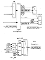
好ましくは、前記方法は、エンジンを含む車両の有効前面投影面積または空気力学的抵抗を推定する方法を更に含み、この方法は、車両の略一定の速度でエンジンの全出力を決定するとともに、その略一定の速度における車両の転がり抵抗に打ち勝つように転がり抵抗出力を決定するステップと、決定された転がり抵抗出力を決定された全現状出力から差し引いて、車両の空気力学的抵抗または有効前面投影面積を決定するステップとを含む。 Preferably, the method further includes a method of estimating an effective front projected area or aerodynamic resistance of a vehicle including the engine, the method determining the total power of the engine at a substantially constant speed of the vehicle, and Determining the rolling resistance output to overcome the rolling resistance of the vehicle at a substantially constant speed, and subtracting the determined rolling resistance output from the determined total current output to determine the vehicle's aerodynamic resistance or effective front projected area Determining.
好ましくは、前記方法は、前記車両が略一定の速度で走行している期間を特定するステップを更に含む。好ましくは、略一定の速度の前記期間を特定するステップは、車載診断システム出力の使用、および/または車両速度、車両加速度、エンジン速度、およびエンジン負荷のうちの1つ以上の使用、および/または車両速度、車両加速度、エンジン速度、およびエンジン負荷のうちの1つ以上と所定の基準レベルとの比較を含む。 Preferably, the method further includes the step of identifying a period during which the vehicle is traveling at a substantially constant speed. Preferably, the step of identifying said period of substantially constant speed comprises using in-vehicle diagnostic system output and / or using one or more of vehicle speed, vehicle acceleration, engine speed, and engine load, and / or Comparing one or more of vehicle speed, vehicle acceleration, engine speed, and engine load with a predetermined reference level.
好ましくは、前記方法は、前記車両が略一定の速度で走行している期間中にわたって前記車両における前記全現状出力を推定するステップを更に含む。好ましくは、前記全現状出力を推定するステップは、前記車載診断システムにより与えられるエンジン負荷パラメータの使用を含む。好ましくは、前記方法は、伝達損失を考慮に入れることによって前記全現状出力を調整するステップを更に含む。好ましくは、伝達損失を考慮に入れるために前記全現状出力を調整するステップは、1つ以上の実験的な出力因子による前記全現状出力の減算および/または乗算のステップを含む。好ましくは、前記方法は、略一定の速度の複数の期間にわたって前記全現状出力に関する移動平均または加重平均を求めるステップを更に含む。 Preferably, the method further comprises the step of estimating the total current output of the vehicle over a period during which the vehicle is traveling at a substantially constant speed. Preferably, the step of estimating the total current output includes the use of an engine load parameter provided by the in-vehicle diagnostic system. Preferably, the method further comprises the step of adjusting the total current output by taking into account transmission losses. Preferably, the step of adjusting the total current output to take into account transmission losses comprises the step of subtracting and / or multiplying the total current output by one or more experimental power factors. Preferably, the method further comprises the step of determining a moving average or a weighted average for the total current output over a plurality of periods of substantially constant speed.
好ましくは、前記方法は、転がり抵抗出力を推定して、前記転がり抵抗出力を前記全現状出力から差し引くことによって、前記空気力学的抵抗出力を推定するステップを更に含む。 Preferably, the method further comprises estimating the aerodynamic resistance output by estimating a rolling resistance output and subtracting the rolling resistance output from the total current output.
好ましくは、転がり抵抗を推定するステップは、前記車両の質量、前記抵抗係数、および前記車両速度の推定値を使用することを含む。好ましくは、転がり抵抗を推定するステップは、転がり抵抗の前記推定において、前記車両が走行している勾配を考慮に入れることを更に含む。 Preferably, the step of estimating the rolling resistance includes using an estimate of the vehicle mass, the resistance coefficient, and the vehicle speed. Preferably, the step of estimating the rolling resistance further comprises taking into account the gradient in which the vehicle is traveling in the estimation of the rolling resistance.
好ましくは、前記方法は、車両の燃料タイプを決定するための方法を更に含み、この方法は、車両の車載診断(OBD)システムの出力パラメータを得るステップと、車両により使用される燃料タイプを決定するために前記出力パラメータを使用するステップとを含む。 Preferably, the method further includes a method for determining a fuel type of the vehicle, the method comprising obtaining an output parameter of an on-vehicle diagnostic (OBD) system of the vehicle and determining a fuel type used by the vehicle. Using the output parameter to do so.
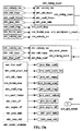
好ましくは、前記方法は、エンジンが減速されているかどうかを特定するステップ、または、排ガスがディーゼルエンジンもしくはガソリンエンジンに特有の範囲内にあるかどうかを測定するステップ、または、燃料圧力をチェックするステップ、または、複数の燃料タイプ特定方法を使用するステップを含むとともに、複数の燃料タイプ特定方法のそれぞれの出力に対して重みづけを割り当てるステップであって、前記重みづけが燃料特定方法のタイプにしたがって変化するステップと、重みづけを加算して、重みづけの総和と所定の閾値とを比較することにより、車両の燃料タイプを決定するステップとを更に含む。好ましくは、前記方法は、エンジンが減速されているかどうかを特定するステップを含み、このステップは、マニホールド絶対圧力(MAP)と閾値とを比較すること、および/または空気流量とエンジン排気量の所定の割合とを比較することとを含む。 Preferably, the method includes identifying whether the engine is decelerated, measuring whether the exhaust gas is within a range specific to a diesel or gasoline engine, or checking the fuel pressure. Or using a plurality of fuel type identification methods, and assigning weights to respective outputs of the plurality of fuel type identification methods, wherein the weights depend on the type of fuel identification method The method further includes the step of changing and determining the fuel type of the vehicle by adding the weights and comparing the sum of the weights with a predetermined threshold. Preferably, the method includes the step of determining whether the engine is decelerating, which comprises comparing the manifold absolute pressure (MAP) with a threshold and / or predetermining air flow and engine displacement. And comparing the ratio of
好ましくは、前記方法は、排ガスがディーゼルエンジンもしくはガソリンエンジンに特有の範囲内にあるかどうかをチェックする、および/またはOBDプロトコルをチェックする、および/またはOBDシステムの燃料状態パラメータ識別子をチェックするステップを含む。 Preferably, the method comprises checking whether the exhaust gas is within a range specific to a diesel or gasoline engine and / or checking the OBD protocol and / or checking the fuel condition parameter identifier of the OBD system. including.
好ましくは、前記方法は、燃料タイプの自動検出の結果を手動で無効にできるステップを更に含む。 Preferably, the method further comprises the step of manually invalidating the result of the automatic detection of the fuel type.
好ましくは、前記方法は、車両の質量を推定する方法を更に含み、前記車両は、車両速度パラメータ、車両加速度パラメータ、および最大加速度パラメータを備える動作パラメータを有し、前記車両がエンジンを有し、前記エンジンがエンジン排気量パラメータとエンジン作動パラメータとを有し、エンジン作動パラメータは、エンジン速度パラメータ、出力パラメータ、最大出力パラメータ、およびエンジン負荷パラメータを備え、前記方法は、動作パラメータのうちの少なくとも1つおよび/またはエンジン作動パラメータのうちの少なくとも1つが所定の範囲内にある適格期間中に取得される車両加速度パラメータの加重平均値または移動平均値を決定するステップと、車両の質量を推定するために車両加速度の前記加重平均値または前記移動平均値を使用するステップとを含む。 Preferably, the method further comprises a method of estimating the mass of the vehicle, the vehicle having operating parameters comprising a vehicle speed parameter, a vehicle acceleration parameter, and a maximum acceleration parameter, the vehicle having an engine, The engine has an engine displacement parameter and an engine operating parameter, the engine operating parameter comprising an engine speed parameter, an output parameter, a maximum output parameter, and an engine load parameter, and the method includes at least one of operating parameters. Determining a weighted or moving average value of a vehicle acceleration parameter obtained during a qualifying period in which at least one of the two and / or engine operating parameters is within a predetermined range, and for estimating a vehicle mass The weighted average value of vehicle acceleration or And using the serial moving average.
好ましくは、前記少なくとも1つの動作パラメータまたはエンジン作動パラメータのうちの少なくとも1つの値は、車載診断システムの少なくとも1つの出力パラメータから得られる。 Preferably, the value of at least one of the at least one operating parameter or engine operating parameter is obtained from at least one output parameter of the in-vehicle diagnostic system.
好ましくは、前記方法は、前記車両がその最大加速度付近で加速していることを少なくとも1つの動作パラメータまたはエンジン作動パラメータのうちの少なくとも1つが示す略ピーク加速度期間を特定するステップを更に含む。 Preferably, the method further comprises identifying a substantially peak acceleration period indicated by at least one of the at least one operating parameter or the engine operating parameter that the vehicle is accelerating near its maximum acceleration.
好ましくは、前記少なくとも1つの出力パラメータは、エンジン負荷、エンジン速度、車両速度、および車両加速度のうちの1つである。 Preferably, the at least one output parameter is one of engine load, engine speed, vehicle speed, and vehicle acceleration.
好ましくは、前記方法は、前記車両加速度と少なくとも1つの所定の加速度閾値とを比較する、および/または前記車両速度と第1の所定の車両速度閾値とを比較する、および/または前記車両速度と第2の所定の車両速度閾値とを比較する、および/または前記エンジン負荷と少なくとも1つの所定のエンジン負荷閾値とを比較する、および/または前記エンジン速度と少なくとも1つの所定のエンジン速度閾値とを比較するステップを更に含む。 Preferably, the method compares the vehicle acceleration with at least one predetermined acceleration threshold, and / or compares the vehicle speed with a first predetermined vehicle speed threshold, and / or with the vehicle speed. Comparing a second predetermined vehicle speed threshold and / or comparing the engine load to at least one predetermined engine load threshold and / or comparing the engine speed to at least one predetermined engine speed threshold. The method further includes a step of comparing.
好ましくは、少なくとも1つの所定の閾値のそれぞれには車両のタイプにしたがった値が割り当てられる。 Preferably, each of the at least one predetermined threshold is assigned a value according to the type of vehicle.
好ましくは、前記加重平均化または前記移動平均化は、前記動作パラメータまたは前記エンジン作動パラメータのうちの少なくとも1つが所定の範囲内にある場合にのみ、あるいは、複数の前記動作パラメータまたは前記エンジン作動パラメータが前記パラメータのために設定された所定の範囲内にある場合にのみ、あるいは、前記動作パラメータまたは前記エンジン作動パラメータの全てが前記パラメータのために設定された所定の範囲内にある場合にのみ行なわれる。 Preferably, the weighted averaging or the moving average is performed only when at least one of the operating parameter or the engine operating parameter is within a predetermined range, or a plurality of the operating parameter or the engine operating parameter. Only if the engine is within a predetermined range set for the parameter or if all of the operating parameters or the engine operating parameters are within a predetermined range set for the parameter It is.
好ましくは、前記方法は、適格期間中に車両のクランクに与えられる力を決定するステップを更に含む。好ましくは、前記方法は、前記力を前記加重平均加速度値または移動平均加速度値で割ることによって前記車両の前記質量を推定するステップを更に含む。好ましくは、前記方法は、少なくとも1つの適格期間が生じたかどうかをチェックするステップを更に含む。 Preferably, the method further comprises the step of determining the force applied to the vehicle crank during the qualification period. Preferably, the method further comprises estimating the mass of the vehicle by dividing the force by the weighted average acceleration value or the moving average acceleration value. Preferably, the method further comprises the step of checking whether at least one eligibility period has occurred.
好ましくは、前記方法は、前記エンジンサイズおよび実験的に決定された定数を使用して前記クランクに与えられる前記力の値を推定するステップを更に含む。好ましくは、前記力の前記値は、適格期間が生じなかった場合に質量の計算で使用される。 Preferably, the method further comprises estimating the value of the force applied to the crank using the engine size and an experimentally determined constant. Preferably, the value of the force is used in the mass calculation when no qualification period has occurred.
好ましくは、前記方法は、前記エンジンを通り抜ける空気流量を得るあるいは推定するステップと、得られたあるいは推定された空気流量を燃料タイプと関連付けられる理論空燃比で割ることによって暫定燃料質量推定値を計算するステップと、前記暫定燃料質量推定値を排ガスの解析から導き出される酸素含有量パラメータで割ることにより燃費を推定するステップとを更に含む。好ましくは、前記方法は、質量空気流量を測定する、および/または圧力、体積流量、および温度の推定値を使用して、理想気体の状態方程式により前記空気流量を推定するステップを含む。 Preferably, the method calculates or calculates a provisional fuel mass estimate by obtaining or estimating an air flow rate through the engine and dividing the obtained or estimated air flow rate by a stoichiometric air / fuel ratio associated with a fuel type. And estimating the fuel consumption by dividing the provisional fuel mass estimate by the oxygen content parameter derived from the exhaust gas analysis. Preferably, the method comprises the steps of measuring the mass air flow and / or estimating the air flow according to an ideal gas equation of state using pressure, volume flow and temperature estimates.
好ましくは、前記方法は、マニホールド絶対圧力センサを使用して、および/またはマニホールド空気温度センサを使用して、前記圧力を推定するステップを含む。 Preferably, the method includes estimating the pressure using a manifold absolute pressure sensor and / or using a manifold air temperature sensor.
好ましくは、前記方法は、エンジンサイズおよびエンジン速度を使用して前記体積流量の前記推定値を計算するステップを含む。 Preferably, the method includes calculating the estimate of the volumetric flow rate using engine size and engine speed.
好ましくは、前記方法は、排気酸素センサからあるいはルックアップテーブルから前記酸素含有量パラメータを得るステップを含み、前記テーブルは、エンジン速度および車両タイプにしたがって酸素含有量値を与える。 Preferably, the method includes the step of obtaining the oxygen content parameter from an exhaust oxygen sensor or from a look-up table, the table providing an oxygen content value according to engine speed and vehicle type.
好ましくは、前記方法は、車両の車載診断システムから得られる少なくとも1つのパラメータを使用して、転がり出力成分、空気力学的抵抗成分、および加速度成分を推定することによって、前記車両の全出力を推定するステップと、燃料のタイプを決定するステップと、前記全出力の前記成分を加算して、前記燃料タイプのエネルギー値および所定のエンジン効率値で割ることによって、前記燃費を推定するステップとを更に含む。 Preferably, the method estimates the total output of the vehicle by estimating a rolling output component, an aerodynamic resistance component, and an acceleration component using at least one parameter obtained from an in-vehicle diagnostic system for the vehicle. Further comprising: determining a fuel type; estimating the fuel consumption by adding the components of the total output and dividing by the energy value of the fuel type and a predetermined engine efficiency value. Including.
好ましくは、前記方法は、車両質量に関する上限および下限を推定するステップを更に含む。好ましくは、前記方法は、質量の前記上限および質量の前記下限のそれぞれに基づいて、燃費に関する上限および下限を推定するステップを更に含む。 Preferably, the method further comprises estimating upper and lower limits for vehicle mass. Preferably, the method further includes estimating an upper limit and a lower limit related to fuel consumption based on each of the upper limit of mass and the lower limit of mass.
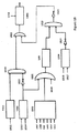
第2の態様によれば、本発明は、車両の燃費を推定するための装置を備え、前記装置は、車両の全出力に関連するパラメータを推定して与えるための推定手段、転がり出力成分に関連するパラメータを推定して与えるための推定手段、空気力学的抵抗成分に関連するパラメータを推定して与えるための推定手段、および加速度成分に関連するパラメータを推定して与えるための推定手段であって、前記全出力推定手段が、車両の車載診断システムに接続されてそこから得られる少なくとも1つのパラメータを受けて使用するようになっている、推定手段と、使用される燃料のタイプを示すパラメータを与えるための手段と、推定された転がり出力成分、推定された空気力学的抵抗成分、および推定された加速度成分に関連するパラメータを受けるとともに、前記全出力の前記成分を加算して、前記燃料タイプのエネルギー値および所定のエンジン効率値で割ることによって前記燃費を推定するように接続される手段とを備える。 According to a second aspect, the present invention comprises a device for estimating the fuel consumption of a vehicle, said device comprising an estimation means for estimating and giving parameters relating to the total output of the vehicle, a rolling output component An estimation means for estimating and giving related parameters, an estimation means for estimating and giving parameters related to aerodynamic resistance components, and an estimation means for estimating and giving parameters related to acceleration components The total output estimating means is connected to an in-vehicle diagnostic system for a vehicle and receives and uses at least one parameter obtained therefrom, and a parameter indicating the type of fuel used And a parameter associated with the estimated rolling output component, the estimated aerodynamic resistance component, and the estimated acceleration component. Rutotomoni, wherein by adding the components of the total output, and a means connected to estimate the fuel consumption by dividing the energy value and a predetermined engine efficiency value of the fuel types.
好ましくは、転がり出力成分を推定するための手段は、車両の質量の推定値を使用する。 Preferably, the means for estimating the rolling output component uses an estimate of the vehicle mass.
好ましくは、空気力学的抵抗を推定するための手段は、車両の前面投影面積の推定値を使用する。 Preferably, the means for estimating aerodynamic resistance uses an estimate of the front projected area of the vehicle.
好ましくは、前記車両質量または前記前面投影面積を推定するための手段は、少なくとも1つの動作パラメータがそのパラメータと関連付けられる値の所定の範囲内にある適格期間を特定するようになっている。 Preferably, the means for estimating the vehicle mass or the front projected area is adapted to identify a qualifying period in which at least one operating parameter is within a predetermined range of values associated with the parameter.
好ましくは、前記車両質量を推定するための手段は、適格期間中に取得される車両加速度読み取り値の加重平均値または移動平均値を決定するようになっている。 Preferably, the means for estimating the vehicle mass is adapted to determine a weighted average value or a moving average value of vehicle acceleration readings acquired during the qualifying period.
好ましくは、前記方法は、車両質量を推定するための前記適格期間を特定するための前記動作パラメータのうちの1つを決定することを更に備え、前記パラメータが前記車両加速度から成る。 Preferably, the method further comprises determining one of the operating parameters for identifying the qualifying period for estimating vehicle mass, wherein the parameter comprises the vehicle acceleration.
好ましくは、前記装置は、前記車両加速度が所定の閾値を上回る適格期間を特定するようになっており、前記閾値が略ピーク加速度を特定するように選択される。好ましくは、前記前面投影面積を推定するための手段は、適格期間中に取得される全出力読み取り値の加重平均値または移動平均値を決定するようになっている。 Preferably, the apparatus is adapted to identify a qualifying period in which the vehicle acceleration exceeds a predetermined threshold, and the threshold is selected to identify a substantially peak acceleration. Preferably, the means for estimating the frontal projection area is adapted to determine a weighted average value or a moving average value of all output readings acquired during the qualification period.
好ましくは、前記装置は、前面投影面積を推定するための前記適格期間を特定するための前記動作パラメータのうちの1つを受けるようになっており、前記パラメータが前記車両加速度から成る。 Preferably, the apparatus is adapted to receive one of the operating parameters for identifying the qualifying period for estimating a frontal projection area, the parameter comprising the vehicle acceleration.
好ましくは、前記装置は、前記車両加速度が所定の閾値間にある適格期間を特定するようになっており、前記閾値は、略定常状態動作の期間を特定するように選択される。 Preferably, the device is adapted to identify a qualifying period in which the vehicle acceleration is between a predetermined threshold, the threshold being selected to identify a period of substantially steady state operation.
好ましくは、前記装置は、少なくとも1つのOBDパラメータを使用して前記車両のためのエンジン負荷報告方策を特定するための手段を更に備える。 Preferably, the apparatus further comprises means for identifying an engine load reporting strategy for the vehicle using at least one OBD parameter.
好ましくは、前記エンジン負荷報告方策を特定するための前記手段は、前記エンジン負荷および前記エンジン速度を得て、前記エンジン負荷を前記エンジン速度と関連付けられるエンジン負荷閾値と更に比較するようになっている。 Preferably, the means for identifying the engine load reporting strategy is adapted to obtain the engine load and the engine speed and further compare the engine load with an engine load threshold associated with the engine speed. .
好ましくは、前記装置は、力とエンジンサイズとの間の実験的に導き出された関係を使用して前記クランクに与えられる力を推定するようになっている。 Preferably, the device is adapted to estimate the force applied to the crank using an experimentally derived relationship between force and engine size.
好ましくは、前記装置は、複数の想定し得るエンジン負荷報告方策のうちのいずれがエンジンを伴う車両の車載診断システムによって使用されるのかを見出すための装置を更に備え、この装置は、車載診断システムパラメータを検査する検査手段と、エンジンが動作しているときに、異なるエンジン負荷報告方策によりもたらされるエンジン負荷値同士の間の差をほぼ最大にするようにエンジン負荷を決定する手段とを備える。 Preferably, the device further comprises a device for finding out which of a plurality of possible engine load reporting strategies are used by the vehicle in-vehicle diagnostic system with the engine, the device comprising: Inspection means for inspecting the parameters and means for determining the engine load so as to substantially maximize the difference between engine load values caused by different engine load reporting strategies when the engine is operating.
好ましくは、前記装置は、異なるエンジン負荷報告方策によりもたらされるエンジン負荷値同士の間の差をほぼ最大にするように前記エンジンがアイドリングしている期間を特定するための特定手段を更に備える。 Preferably, the apparatus further comprises identifying means for identifying a period of time that the engine is idling so as to substantially maximize the difference between engine load values caused by different engine load reporting strategies.
好ましくは、前記特定手段は、前記車載診断システムパラメータを使用することによって、および/または前記エンジン速度とアイドリング速度閾値とを比較することによって、前記エンジンがアイドリングしている期間を特定する。 Preferably, the identifying means identifies a period of time during which the engine is idling by using the in-vehicle diagnostic system parameters and / or by comparing the engine speed with an idling speed threshold.
好ましくは、前記装置は、前記エンジンが作動していた時間を考慮に入れるために前記アイドリング閾値速度を調整するための手段を更に備える。 Preferably, the apparatus further comprises means for adjusting the idling threshold speed to take into account the time that the engine has been running.
好ましくは、前記装置は、エンジン温度を考慮に入れるために、および/またはエンジン排気量を考慮に入れるために、および/または前記エンジンの燃料タイプを考慮に入れるために、および/またはエンジン排気量を考慮に入れるために前記アイドリング閾値速度が調整されるようになっている。 Preferably, the device is for taking into account engine temperature and / or to take into account engine displacement and / or to take into account the fuel type of the engine and / or engine displacement. The idling threshold speed is adjusted to take into account.
好ましくは、前記装置は、クラッチプレートとの係合により前記車両が静止状態に保持されているかどうかを見出すためのクラッチチェック手段を更に備える。 Preferably, the device further comprises clutch check means for finding out whether the vehicle is held stationary by engagement with a clutch plate.
好ましくは、前記クラッチチェック手段は、報告されたエンジン負荷とエンジン負荷閾値とを比較する。好ましくは、前記装置は、前記エンジンが作動していることをチェックするためのエンジンチェック手段を更に備える。 Preferably, the clutch check means compares the reported engine load with an engine load threshold. Preferably, the apparatus further comprises engine check means for checking that the engine is operating.
好ましくは、前記装置は、前記見出された報告方策の持続性チェックを行なうための持続性チェック手段を更に備える。 Preferably, the apparatus further comprises a persistence check means for performing a persistence check of the found reporting policy.
好ましくは、前記装置は、前記見出された報告方策に関する指標を記憶するためのラッチ回路を更に備える。 Preferably, the apparatus further comprises a latch circuit for storing an indication relating to the found reporting strategy.
好ましくは、前記装置は、前記車両の速度が前記報告方策を見出す際に使用される速度チェック手段を更に備える。 Preferably, the apparatus further comprises speed check means used when the speed of the vehicle finds the reporting strategy.
好ましくは、前記車両の前記速度は、前記車両がアイドリングしている期間を特定するために使用される。 Preferably, the speed of the vehicle is used to identify a period during which the vehicle is idling.
好ましくは、前記装置は、エンジンを含む車両の有効前面投影面積または空気力学的抵抗を推定するための装置を更に備え、この装置は、車両の略一定の速度でエンジンの全出力を決定するための装置と、その略一定の速度における車両の転がり抵抗に打ち勝つように転がり抵抗出力を決定するための装置と、決定された転がり抵抗出力を決定された全現状出力から差し引いて、車両の空気力学的抵抗または有効前面投影面積を決定するための装置とを備える。 Preferably, the device further comprises a device for estimating the effective front projected area or aerodynamic resistance of the vehicle including the engine, which device determines the total power of the engine at a substantially constant speed of the vehicle. The vehicle's aerodynamics by subtracting the determined rolling resistance output from the determined total current output and the device for determining the rolling resistance output to overcome the rolling resistance of the vehicle at its substantially constant speed. And an apparatus for determining an effective frontal projected area.
好ましくは、前記装置は、前記車両が略一定の速度で走行している期間を特定するようになっている特定手段を更に備える。好ましくは、前記特定手段は、車載診断システム出力を使用して、および/または前記車両速度、前記車両加速度、前記エンジン速度、および、前記エンジン負荷のうちの1つ以上を使用して、略一定の速度の期間を特定するようになっている。 Preferably, the apparatus further includes a specifying unit configured to specify a period during which the vehicle is traveling at a substantially constant speed. Preferably, the identifying means is substantially constant using an in-vehicle diagnostic system output and / or using one or more of the vehicle speed, the vehicle acceleration, the engine speed, and the engine load. The duration of the speed is to be specified.
好ましくは、前記装置は、前記車両における前記全現状出力の推定値を略一定の速度で走行している期間中にわたっておよび/または前記OBDシステムにより与えられるエンジン負荷パラメータを使用することにより与えるようになっている推定手段を更に備える。 Preferably, the device provides an estimate of the total current output in the vehicle over a period of traveling at a substantially constant speed and / or by using engine load parameters provided by the OBD system. The estimation means is further provided.
好ましくは、前記調整手段は、1つ以上の実験的な出力因子による前記全現状出力の減算および/または乗算によって伝達損失を考慮に入れるために現状出力を調整するようになっている。好ましくは、前記装置は、略一定の速度の複数の期間にわたって前記全現状出力に関する移動平均または加重平均を求めるようになっている平均化手段を更に備える。 Preferably, the adjusting means is adapted to adjust the current output in order to take into account transmission losses by subtraction and / or multiplication of the total current output by one or more experimental output factors. Preferably, the apparatus further comprises averaging means adapted to determine a moving average or a weighted average for the total current output over a plurality of periods of substantially constant speed.
好ましくは、前記特定手段は、車両速度、車両加速度、エンジン速度、およびエンジン負荷のうちの1つ以上と所定の基準レベルとを比較することによって略一定の速度の期間を特定するようになっている。 Preferably, the specifying means specifies a period of substantially constant speed by comparing one or more of vehicle speed, vehicle acceleration, engine speed, and engine load with a predetermined reference level. Yes.
好ましくは、前記装置は、転がり抵抗出力を推定して、前記転がり抵抗出力を全現状出力から差し引くことによって、前記空気力学的抵抗出力を推定するための空気力学的抵抗推定手段を更に備える。 Preferably, the apparatus further comprises aerodynamic resistance estimation means for estimating the aerodynamic resistance output by estimating a rolling resistance output and subtracting the rolling resistance output from a total current output.
好ましくは、前記転がり抵抗推定手段は、前記車両の質量、前記抵抗係数、および前記車両速度の推定値を使用することによって前記転がり抵抗を推定する。 Preferably, the rolling resistance estimation means estimates the rolling resistance by using estimated values of the mass of the vehicle, the resistance coefficient, and the vehicle speed.
好ましくは、前記転がり抵抗推定手段は、転がり抵抗の前記計算において、前記車両が走行している勾配を考慮に入れる。 Preferably, the rolling resistance estimating means takes into account a gradient in which the vehicle is traveling in the calculation of the rolling resistance.
好ましくは、前記装置は、車両の燃料タイプを決定するための装置を更に備え、この装置は、車両の車載診断(OBD)システムの出力パラメータを得るための手段と、車両により使用される燃料タイプを決定するために前記出力パラメータを使用する手段とを備える。 Preferably, the device further comprises a device for determining the fuel type of the vehicle, the device comprising means for obtaining output parameters of the vehicle on-board diagnostic (OBD) system and the fuel type used by the vehicle Means for using said output parameter to determine.
好ましくは、前記装置は、エンジンが減速しているかどうかを特定するための減速特定手段を備える。 Preferably, the device includes deceleration specifying means for specifying whether or not the engine is decelerating.
好ましくは、前記装置は、マニホールド絶対圧力(MAP)と所定の閾値とを比較するようになっている圧力比較手段、および/または空気流量がエンジン排気量の所定の割合を下回るかどうかを決定するようになっている空気流量比較手段、および/または排ガスがディーゼルエンジンもしくはガソリンエンジンに特有の範囲内にあるかどうかを測定するための排ガス温度比較手段、および/またはOBDプロトコルをチェックするためのプロトコルチェック手段、および/またはOBDシステムの燃料状態パラメータ識別子をチェックするための燃料状態チェック手段、および/または燃料タイプの自動検出の結果をユーザが無効にできるようにする手動無効化を備える。 Preferably, the apparatus determines pressure comparison means adapted to compare the manifold absolute pressure (MAP) to a predetermined threshold and / or whether the air flow is below a predetermined percentage of engine displacement. Air flow comparison means adapted and / or exhaust gas temperature comparison means for measuring whether the exhaust gas is within a range specific to a diesel or gasoline engine, and / or a protocol for checking the OBD protocol It comprises a checking means and / or a fuel condition checking means for checking the fuel condition parameter identifier of the OBD system and / or a manual invalidation that allows the user to invalidate the result of the automatic detection of the fuel type.
好ましくは、前記装置は、エンジンが減速されているかどうかを特定するための減速特定手段、または、排ガスがディーゼルエンジンもしくはガソリンエンジンに特有の範囲内にあるかどうかを測定するための排ガス温度比較手段、または、燃料圧力をチェックするための燃料圧力チェック手段、または、複数の燃料タイプ特定手段を更に備えるとともに、更に、複数の燃料タイプ特定手段のそれぞれの出力に対して重みづけを割り当てるための重みづけ手段であって、前記重みづけが燃料特定手段のタイプと燃料特定の出力とにしたがって変化する重みづけ手段と、重みづけを加算して、重みづけの総和と所定の閾値とを比較することにより、車両の燃料タイプに関する決定を可能にする決定手段とを備える。 Preferably, the apparatus is a deceleration specifying means for specifying whether the engine is decelerated, or an exhaust gas temperature comparing means for measuring whether the exhaust gas is within a range specific to a diesel engine or a gasoline engine. Or a fuel pressure checking means for checking the fuel pressure, or a plurality of fuel type specifying means, and a weight for assigning a weight to each output of the plurality of fuel type specifying means A weighting means for changing the weight according to the type of the fuel specifying means and the fuel specific output, and adding the weight to compare the sum of the weights with a predetermined threshold value. And determining means for enabling determination regarding the fuel type of the vehicle.
好ましくは、前記装置は、エンジンを有する車両の質量を推定するための装置を更に備え、前記装置は、車両速度パラメータ、車両加速度パラメータ、および最大加速度パラメータを備える車両の動作パラメータを決定するための手段と、エンジン排気量パラメータと、エンジン速度パラメータ、出力パラメータ、最大出力パラメータ、およびエンジン負荷パラメータを備えるエンジン作動パラメータとを決定するための手段と、動作パラメータのうちの少なくとも1つおよび/またはエンジン作動パラメータのうちの少なくとも1つが所定の範囲内にある適格期間中に取得される車両加速度パラメータの加重平均値または移動平均値を決定するための手段と、車両の質量を推定するために車両加速度の前記加重平均値または前記移動平均値を使用するための手段とを備える。 Preferably, the apparatus further comprises a device for estimating the mass of a vehicle having an engine, the device for determining a vehicle operating parameter comprising a vehicle speed parameter, a vehicle acceleration parameter, and a maximum acceleration parameter. Means, means for determining an engine displacement parameter, an engine operating parameter comprising an engine speed parameter, an output parameter, a maximum output parameter, and an engine load parameter, at least one of the operating parameter and / or the engine Means for determining a weighted or moving average of vehicle acceleration parameters acquired during a qualifying period in which at least one of the operating parameters is within a predetermined range; and vehicle acceleration to estimate the vehicle mass The weighted average value or the moving average value of And means for using.
好ましくは、前記装置は、前記少なくとも1つの動作パラメータまたはエンジン作動パラメータのうちの少なくとも1つの値を車載診断システムの少なくとも1つの出力パラメータから得るようになっている。 Preferably, the device is adapted to obtain a value of at least one of the at least one operating parameter or engine operating parameter from at least one output parameter of the in-vehicle diagnostic system.
好ましくは、前記装置は、前記車両がその最大加速度付近で加速していることを前記少なくとも1つの動作パラメータまたはエンジン作動パラメータのうちの少なくとも1つが示す略ピーク加速度期間を特定するようになっている。 Preferably, the apparatus is adapted to identify a substantially peak acceleration period during which at least one of the at least one operating parameter or engine operating parameter indicates that the vehicle is accelerating near its maximum acceleration. .
好ましくは、前記少なくとも1つの出力パラメータは、エンジン負荷、エンジン速度、車両速度、および車両加速度のうちの1つである。 Preferably, the at least one output parameter is one of engine load, engine speed, vehicle speed, and vehicle acceleration.
好ましくは、前記装置は、前記車両加速度と少なくとも1つの所定の加速度閾値とを比較するための比較手段を更に備える。 Preferably, the apparatus further comprises comparison means for comparing the vehicle acceleration with at least one predetermined acceleration threshold.
好ましくは、前記装置は、前記車両速度と第1の所定の車両速度閾値とを比較するようになっている比較手段を更に備える。 Preferably, the apparatus further comprises comparison means adapted to compare the vehicle speed with a first predetermined vehicle speed threshold.
好ましくは、前記装置は、前記車両速度と第2の所定の車両速度閾値とを比較する、および/または前記エンジン負荷と少なくとも1つの所定のエンジン負荷閾値とを比較する、および/または前記エンジン速度と少なくとも1つの所定のエンジン速度閾値とを比較するための比較手段を更に備える。好ましくは、前記少なくとも1つの所定の閾値のそれぞれには車両のタイプにしたがった値が割り当てられる。 Preferably, the device compares the vehicle speed to a second predetermined vehicle speed threshold and / or compares the engine load to at least one predetermined engine load threshold and / or the engine speed. And a comparison means for comparing the at least one predetermined engine speed threshold. Preferably, each of the at least one predetermined threshold is assigned a value according to the type of vehicle.
好ましくは、前記装置は、前記加重平均化または前記移動平均化が、前記動作パラメータまたは前記エンジンパラメータのうちの少なくとも1つが前記パラメータにおける所定の範囲内にある場合にのみ、あるいは、複数の前記動作パラメータまたは前記エンジンパラメータが前記パラメータのために設定された所定の範囲内にある場合にのみ、あるいは、前記動作パラメータの全てが前記パラメータのために設定された所定の範囲内にある場合にのみ行なわれるようになっている。 Preferably, the apparatus is configured such that the weighted average or the moving average is only when at least one of the operating parameter or the engine parameter is within a predetermined range in the parameter, or a plurality of the operating Only if the parameter or the engine parameter is within a predetermined range set for the parameter, or only if all of the operating parameters are within a predetermined range set for the parameter It is supposed to be.
好ましくは、前記装置は、適格期間中に前記クランクに与えられる力を決定するための力決定手段を更に備える。 Preferably, the device further comprises force determining means for determining the force applied to the crank during the qualifying period.
好ましくは、前記装置は、前記力を前記加重平均加速度値または移動平均加速度値で割ることによって前記車両の前記質量を推定するための推定手段を更に備える。 Preferably, the apparatus further comprises estimation means for estimating the mass of the vehicle by dividing the force by the weighted average acceleration value or the moving average acceleration value.
好ましくは、前記装置は、少なくとも1つの適格期間が生じたかどうかをチェックするためのチェック手段を更に備える。 Preferably, the device further comprises check means for checking whether at least one qualifying period has occurred.
好ましくは、前記装置は、前記エンジンサイズおよび実験的に決定された定数を使用して前記クランクに与えられる前記力の値を推定するための推定手段を更に備える。 Preferably, the apparatus further comprises estimation means for estimating the value of the force applied to the crank using the engine size and an experimentally determined constant.
好ましくは、前記装置は、適格期間が生じなかった場合に質量の計算において前記力の前記値を使用するようになっている。 Preferably, the device is adapted to use the value of the force in a mass calculation when no qualification period has occurred.
好ましくは、前記装置は、車両のエンジンの燃費を推定するための装置を更に備え、この装置は、前記エンジンを通り抜ける空気流量を得るあるいは推定するための手段と、得られたあるいは推定された空気流量を燃料タイプと関連付けられる理論空燃比で割ることによって暫定燃料質量推定値を計算するための手段と、前記暫定燃料質量推定値を排ガスの解析から導き出される酸素含有量パラメータで割ることにより燃費を推定するための手段とを備える。 Preferably, the device further comprises a device for estimating the fuel consumption of the engine of the vehicle, the device comprising means for obtaining or estimating the air flow rate through the engine and the obtained or estimated air. Means for calculating a provisional fuel mass estimate by dividing the flow rate by the stoichiometric air-fuel ratio associated with the fuel type; and fuel consumption by dividing the provisional fuel mass estimate by an oxygen content parameter derived from an exhaust gas analysis. Means for estimating.
好ましくは、前記決定手段は、質量空気流量センサを使用する測定手段、および/または圧力、体積流量、および温度の推定値を使用して、理想気体の状態方程式により前記空気流量を推定するための推定手段を更に備える。 Preferably, said determining means is for measuring said air flow according to an ideal gas equation of state using measuring means using a mass air flow sensor and / or pressure, volume flow and temperature estimates. An estimation means is further provided.
好ましくは、前記装置は、マニホールド絶対圧力センサを使用して、および/またはマニホールド空気温度センサを使用して、前記圧力推定値を得るようになっている。 Preferably, the apparatus is adapted to obtain the pressure estimate using a manifold absolute pressure sensor and / or using a manifold air temperature sensor.
好ましくは、前記装置は、エンジンサイズおよびエンジン速度を使用して前記体積流量の前記推定値を計算するようになっている。 Preferably, the device is adapted to calculate the estimate of the volumetric flow rate using engine size and engine speed.
好ましくは、前記装置は、排気酸素センサからあるいはルックアップテーブルから前記酸素含有量パラメータを得るようになっており、前記テーブルは、エンジン速度および車両タイプにしたがって酸素含有量値を与える。 Preferably, the apparatus is adapted to obtain the oxygen content parameter from an exhaust oxygen sensor or from a look-up table, the table providing an oxygen content value according to engine speed and vehicle type.
好ましくは、前記装置は、車両の車載診断システムから得られる少なくとも1つのパラメータを使用して、転がり出力成分、空気力学的抵抗成分、および加速度成分を推定することによって、前記車両の全出力を推定するための推定手段と、燃料のタイプを決定することと、前記全出力の前記成分を加算して、前記燃料タイプのエネルギー値および所定のエンジン効率値で割ることによって、前記燃費を推定することとを更に備える。 Preferably, the device estimates the total output of the vehicle by estimating a rolling output component, an aerodynamic resistance component, and an acceleration component using at least one parameter obtained from an in-vehicle diagnostic system for the vehicle. Estimating the fuel consumption by determining the fuel type, adding the components of the total output, and dividing by the energy value of the fuel type and a predetermined engine efficiency value And further comprising.
好ましくは、前記装置は、車両質量に関する上限および下限を推定するための推定手段を更に備える。 Preferably, the apparatus further includes estimation means for estimating an upper limit and a lower limit related to vehicle mass.
好ましくは、前記装置は、質量の前記上限および質量の前記下限のそれぞれに基づいて、燃費に関する上限および下限を推定するための推定手段を更に備える。 Preferably, the apparatus further includes estimation means for estimating an upper limit and a lower limit related to fuel consumption based on each of the upper limit of mass and the lower limit of mass.
更なる態様によれば、本発明は、複数の想定し得るエンジン負荷報告方策のうちのいずれがエンジンを伴う車両の車載診断システムによって使用されるのかを見出すための装置であって、車載診断システムパラメータを検査するための検査手段と、エンジンが動作しているときに、異なるエンジン負荷報告方策によりもたらされるエンジン負荷値同士の間の差をほぼ最大にするようにエンジン負荷を決定するための手段とを備える装置を提供する。 According to a further aspect, the present invention is an apparatus for finding out which of a plurality of possible engine load reporting strategies are used by an in-vehicle diagnostic system for a vehicle with an engine, the in-vehicle diagnostic system Inspection means for inspecting parameters and means for determining engine load so as to substantially maximize the difference between engine load values caused by different engine load reporting strategies when the engine is running An apparatus is provided.
更なる態様によれば、本発明は、複数の想定し得るエンジン負荷報告方策のうちのいずれがエンジンを伴う車両の車載診断システムによって使用されるのかを見出すための方法であって、車載診断システムパラメータを検査するステップと、エンジンが動作しているときに、異なるエンジン負荷報告方策によりもたらされるエンジン負荷値同士の間の差をほぼ最大にするようにエンジン負荷を決定するステップとを含む方法を提供する。 According to a further aspect, the present invention is a method for finding out which of a plurality of possible engine load reporting strategies are used by an in-vehicle diagnostic system for a vehicle with an engine, the in-vehicle diagnostic system Checking the parameters and determining the engine load to approximately maximize the difference between engine load values caused by different engine load reporting strategies when the engine is operating. provide.
更なる態様によれば、本発明は、エンジンを含む車両の有効前面投影面積または空気力学的抵抗を推定する方法であって、車両の略一定の速度でエンジンの全出力を決定するとともに、その略一定の速度における車両の転がり抵抗に打ち勝つように転がり抵抗出力を決定するステップと、決定された転がり抵抗出力を決定された全現状出力から差し引いて、車両の空気力学的抵抗または有効前面投影面積を決定するステップとを含む方法を提供する。 According to a further aspect, the present invention is a method for estimating an effective front projected area or aerodynamic resistance of a vehicle including an engine, wherein the total power of the engine is determined at a substantially constant speed of the vehicle, and Determining the rolling resistance output to overcome the rolling resistance of the vehicle at a substantially constant speed, and subtracting the determined rolling resistance output from the determined total current output to determine the vehicle's aerodynamic resistance or effective front projected area Determining a method.
更なる態様によれば、本発明は、エンジンを含む車両の有効前面投影面積または空気力学的抵抗を推定するための装置であって、車両の略一定の速度でエンジンの全出力を決定するための装置と、その略一定の速度における車両の転がり抵抗に打ち勝つように転がり抵抗出力を決定するための装置と、決定された転がり抵抗出力を決定された全現状出力から差し引いて、車両の空気力学的抵抗または有効前面投影面積を決定するための装置とを備える装置を提供する。 According to a further aspect, the present invention is an apparatus for estimating the effective front projected area or aerodynamic resistance of a vehicle including an engine for determining the total output of the engine at a substantially constant speed of the vehicle. The vehicle's aerodynamics by subtracting the determined rolling resistance output from the determined total current output and the device for determining the rolling resistance output to overcome the rolling resistance of the vehicle at its substantially constant speed. And an apparatus for determining an effective frontal projected area.
更なる態様によれば、本発明は、車両の燃料タイプを決定するための装置であって、車両の車載診断(OBD)システムの出力パラメータを得るための手段と、車両により使用される燃料タイプを決定するために前記出力パラメータを使用するための手段とを備える装置を提供する。 According to a further aspect, the present invention is an apparatus for determining a fuel type of a vehicle, means for obtaining an output parameter of an on-vehicle diagnostic (OBD) system of the vehicle, and a fuel type used by the vehicle. Means for using the output parameter to determine.
好ましくは、前記装置は、エンジンが減速されているかどうかを特定するための減速特定手段、または、排ガスがディーゼルエンジンもしくはガソリンエンジンに特有の範囲内にあるかどうかを測定するための排ガス温度比較手段、または、燃料圧力をチェックするための燃料圧力チェック手段、または、複数の燃料タイプ特定手段を備えるとともに、複数の燃料タイプ特定手段のそれぞれの出力に対して重みづけを割り当てるための重みづけ手段であって、前記重みづけが燃料特定手段のタイプと燃料特定の出力とにしたがって変化する重みづけ手段と、重みづけを加算して、重みづけの総和と所定の閾値とを比較することにより、車両の燃料タイプに関する決定を可能にする決定手段とを更に備える。 Preferably, the apparatus is a deceleration specifying means for specifying whether the engine is decelerated, or an exhaust gas temperature comparing means for measuring whether the exhaust gas is within a range specific to a diesel engine or a gasoline engine. Or a fuel pressure checking means for checking the fuel pressure, or a weighting means for assigning a weight to each output of the plurality of fuel type specifying means and including a plurality of fuel type specifying means The weighting means in which the weight changes according to the type of the fuel specifying means and the fuel specific output, and the weight is added, and the total sum of the weights is compared with a predetermined threshold value. And determining means for enabling determination regarding the fuel type.
更なる態様によれば、本発明は、車両の燃料タイプを決定するための方法であって、車両の車載診断(OBD)システムの出力パラメータを得るステップと、車両により使用される燃料タイプを決定するために前記出力パラメータを使用するステップとを含む方法を提供する。 According to a further aspect, the present invention is a method for determining a fuel type of a vehicle, obtaining an output parameter of a vehicle on-board diagnostic (OBD) system, and determining a fuel type used by the vehicle. Using the output parameter to do so.
好ましくは、前記方法は、エンジンが減速されているかどうかを特定するステップ、または、排ガスがディーゼルエンジンもしくはガソリンエンジンに特有の範囲内にあるかどうかを測定するステップ、または、燃料圧力をチェックするステップ、または、複数の燃料タイプ特定方法を使用するステップを含むとともに、燃料特定方法のタイプと燃料特定方法の出力とにしたがって複数の燃料タイプ特定方法のそれぞれの出力に対して重みづけを割り当てるステップと、重みづけを加算して、重みづけの総和と所定の閾値とを比較することにより、車両の燃料タイプを決定するステップとを更に含む。 Preferably, the method includes identifying whether the engine is decelerated, measuring whether the exhaust gas is within a range specific to a diesel or gasoline engine, or checking the fuel pressure. Or using a plurality of fuel type identification methods and assigning weights to respective outputs of the plurality of fuel type identification methods according to the type of fuel identification method and the output of the fuel identification method; And determining the fuel type of the vehicle by adding weights and comparing the sum of the weights with a predetermined threshold.
更なる態様によれば、本発明は、車両の質量を推定する方法を提供し、前記車両は、車両速度パラメータ、車両加速度パラメータ、および最大加速度パラメータを備える動作パラメータを有し、前記車両がエンジンを有し、前記エンジンがエンジン排気量パラメータとエンジン作動パラメータとを有し、エンジン作動パラメータは、エンジン速度パラメータ、出力パラメータ、最大出力パラメータ、およびエンジン負荷パラメータを備え、前記方法は、動作パラメータのうちの少なくとも1つおよび/またはエンジン作動パラメータのうちの少なくとも1つが所定の範囲内にある適格期間中に取得される車両加速度パラメータの加重平均値または移動平均値を決定するステップと、車両の質量を推定するために車両加速度の前記加重平均値または前記移動平均値を使用するステップとを含む。 According to a further aspect, the present invention provides a method for estimating the mass of a vehicle, the vehicle having operating parameters comprising a vehicle speed parameter, a vehicle acceleration parameter, and a maximum acceleration parameter, wherein the vehicle is an engine The engine has an engine displacement parameter and an engine operating parameter, the engine operating parameter comprising an engine speed parameter, an output parameter, a maximum output parameter, and an engine load parameter; Determining a weighted or moving average value of vehicle acceleration parameters obtained during a qualifying period in which at least one of the engine parameters and / or at least one of the engine operating parameters is within a predetermined range; To estimate the weighted average of vehicle acceleration Includes a step of using the moving average.
更なる態様によれば、本発明は、エンジンを有する車両の質量を推定するための装置を提供し、前記装置は、車両速度パラメータ、車両加速度パラメータ、および最大加速度パラメータを備える車両の動作パラメータを決定するための手段と、エンジン排気量パラメータと、エンジン速度パラメータ、出力パラメータ、最大出力パラメータ、およびエンジン負荷パラメータを備えるエンジン作動パラメータとを決定するための手段と、動作パラメータのうちの少なくとも1つおよび/またはエンジン作動パラメータのうちの少なくとも1つが所定の範囲内にある適格期間中に取得される車両加速度パラメータの加重平均値または移動平均値を決定するための手段と、車両の質量を推定するために車両加速度の前記加重平均値または前記移動平均値を使用するための手段とを備える。 According to a further aspect, the present invention provides an apparatus for estimating the mass of a vehicle having an engine, said apparatus comprising a vehicle operating parameter comprising a vehicle speed parameter, a vehicle acceleration parameter, and a maximum acceleration parameter. At least one of means for determining, means for determining an engine displacement parameter, an engine operating parameter comprising an engine speed parameter, an output parameter, a maximum output parameter, and an engine load parameter; and an operating parameter And / or means for determining a weighted or moving average value of a vehicle acceleration parameter obtained during a qualifying period in which at least one of the engine operating parameters is within a predetermined range, and estimating the mass of the vehicle For the weighted average value of the vehicle acceleration or the moving average And means for using the value.
更なる態様によれば、本発明は、車両のエンジンの燃費を推定する方法を提供し、前記方法は、前記エンジンを通り抜ける空気流量を得るあるいは推定するステップと、得られたあるいは推定された空気流量を燃料タイプと関連付けられる理論空燃比で割ることによって暫定燃料質量推定値を計算するステップと、前記暫定燃料質量推定値を排ガスの解析から導き出される酸素含有量パラメータで割ることにより燃費を推定するステップとを含む。 According to a further aspect, the present invention provides a method for estimating the fuel consumption of a vehicle engine, the method comprising obtaining or estimating an air flow rate through the engine, and obtained or estimated air. Calculating a provisional fuel mass estimate by dividing the flow rate by the stoichiometric air / fuel ratio associated with the fuel type, and estimating the fuel consumption by dividing the provisional fuel mass estimate by an oxygen content parameter derived from an exhaust gas analysis Steps.
更なる態様によれば、本発明は、車両のエンジンの燃費を推定するための装置であって、前記エンジンを通り抜ける空気流量を得るあるいは推定するための手段と、得られたあるいは推定された空気流量を燃料タイプと関連付けられる理論空燃比で割ることによって暫定燃料質量推定値を計算するための手段と、前記暫定燃料質量推定値を排ガスの解析から導き出される酸素含有量パラメータで割ることにより燃費を推定するための手段とを備える装置を提供する。 According to a further aspect, the present invention is an apparatus for estimating the fuel consumption of a vehicle engine, means for obtaining or estimating the air flow rate through the engine, and the obtained or estimated air. Means for calculating a provisional fuel mass estimate by dividing the flow rate by the stoichiometric air-fuel ratio associated with the fuel type; and fuel consumption by dividing the provisional fuel mass estimate by an oxygen content parameter derived from an exhaust gas analysis. And a means for estimating.
更なる態様によれば、本発明は、車両の燃費を推定する方法であって、それぞれが特定の異なるパラメータに関連するデータセットを収集するステップと、選択されたデータまたは他のデータの一部の値が適格値(qualifying value)を有する場合にのみ選択されたデータを選択的に処理して燃費を定めるステップとを含む方法を提供する。 According to a further aspect, the present invention is a method for estimating the fuel consumption of a vehicle, comprising collecting a data set each associated with a particular different parameter, and a portion of selected data or other data Selectively processing the selected data only when the value of qualifying value has a qualifying value to determine fuel consumption.
前記適格値は、所定の限界同士の間にあるのが好ましく、ほぼ設定値であり、または、ゼロあるいはほぼゼロである。 The qualifying value is preferably between predetermined limits and is substantially a set value, or is zero or substantially zero.
好ましくは、前記方法は、車両がアイドリングしているときに収集されるデータを処理することにより、車両の車載診断システムのエンジン負荷報告方策を決定するステップを含む。 Preferably, the method includes the step of determining an engine load reporting strategy of the vehicle's on-board diagnostic system by processing data collected when the vehicle is idling.
好ましくは、前記方法は、車両が略一定の速度で走行しているときに収集されたあるいは収集されているデータを処理することにより、車両により使用される燃料のタイプを決定して、車両のエンジンの出力を与えるステップを含む。 Preferably, the method determines the type of fuel used by the vehicle by processing data collected or collected when the vehicle is traveling at a substantially constant speed, and Providing an engine output.
好ましくは、前記方法は、速度がほぼ設定値未満のときに収集されるデータを処理することにより車両のピーク加速度を決定するステップを含む。 Preferably, the method includes the step of determining the peak acceleration of the vehicle by processing data collected when the speed is approximately below a set value.
更なる態様によれば、本発明は、車両の燃費を推定するための装置であって、セットがそれぞれ特定の異なるパラメータに関連するデータを収集するようになっている手段と、選択されたデータまたは他のデータの一部の値が適格値を有する場合にのみ選択されたデータを選択的に処理して燃費を定めるようになっている手段とを備える装置を提供する。 According to a further aspect, the present invention is an apparatus for estimating the fuel consumption of a vehicle, the means each of which is adapted to collect data relating to a particular different parameter, and selected data Or a means for selectively processing selected data only when some values of other data have qualified values to determine fuel consumption.
好ましくは、前記適格値は、所定の限界同士の間にあるとともに、ほぼ設定値であり、または、ゼロあるいはほぼゼロである。 Preferably, the qualifying value is between predetermined limits and is substantially a set value, or is zero or substantially zero.
好ましくは、前記装置は、車両がアイドリングしているときに収集されるデータを処理することにより、車両の車載診断システムのエンジン負荷報告方策を決定するようになっている手段を含む。 Preferably, the apparatus includes means adapted to determine the engine load reporting strategy of the in-vehicle diagnostic system of the vehicle by processing data collected when the vehicle is idling.
好ましくは、前記装置は、車両が略一定の速度で走行しているときに収集されたあるいは収集されているデータを処理することにより、車両により使用される燃料のタイプを決定して、車両のエンジンの出力を与えるようになっている手段を含む。 Preferably, the device determines the type of fuel used by the vehicle by processing the data collected or collected when the vehicle is traveling at a substantially constant speed, Including means adapted to provide engine power.
好ましくは、前記装置は、速度がほぼ設定値未満のときに収集されるデータを処理することにより車両のピーク加速度を決定するようになっている手段を含む。 Preferably, the apparatus includes means adapted to determine the peak acceleration of the vehicle by processing data collected when the speed is approximately less than a set value.
ここで、添付図面を参照して、本発明の好ましい態様を単なる一例として説明する。 A preferred embodiment of the present invention will now be described by way of example only with reference to the accompanying drawings.
1つの実施形態によれば、燃費を推定する方法が図1に示されており、この方法は、特定の時間間隔の旅程中および連続的な時間間隔にわたる燃費の動的な推定を行なう。 According to one embodiment, a method for estimating fuel consumption is shown in FIG. 1, which provides a dynamic estimation of fuel consumption during a specific time interval itinerary and over successive time intervals.
この方法によれば、エンジンを通り抜ける空気流量が、特定の時間間隔にわたって、連続する時間間隔にわたって、旅程の全体にわたって得られあるいは推定されてもよい。この空気流量は、車載診断システム(OBD)から取得されるマニホールド絶対圧力および温度などのデータ、例えば、OBD動作の各報告サイクルで取得されるデータに基づいて得られあるいは推定されてもよく、そのようなサイクルは、燃費推定の適用を受ける時間間隔を規定してもよい。あるいは、空気流量は、最大空気流量センサが存在する場合には、その最大空気流量センサから得られてもよい。このとき、各時間間隔中に車両によって処理される燃料質量の暫定的推定値が、そのような空気流量を消費されるべき燃料のタイプと関連する既知の理論空燃比で割ることによって得られてもよい。それから、燃費値は、燃料質量値と排ガスの分析から得られる酸素値とから推定されてもよい。排ガスは、エンジンを通過した燃焼されないままの酸素を含む。本発明の一実施形態では、酸素値は、ラムダセンサなどの酸素センサから取得される。別の実施形態では、酸素値は、検査を行なうことによって得られ、酸素値は、車両タイプと現在のエンジン負荷とに基づいて選択される。 According to this method, the air flow rate through the engine may be obtained or estimated over the entire itinerary over a specific time interval, over successive time intervals. This air flow rate may be obtained or estimated based on data such as manifold absolute pressure and temperature obtained from an onboard diagnostic system (OBD), for example, data obtained in each reporting cycle of OBD operation. Such a cycle may define a time interval that is subject to application of fuel consumption estimation. Alternatively, the air flow rate may be obtained from a maximum air flow sensor if a maximum air flow sensor is present. At this time, a provisional estimate of the fuel mass processed by the vehicle during each time interval is obtained by dividing such air flow rate by the known stoichiometric air / fuel ratio associated with the type of fuel to be consumed. Also good. Then, the fuel consumption value may be estimated from the fuel mass value and the oxygen value obtained from the analysis of the exhaust gas. The exhaust gas contains unburned oxygen that has passed through the engine. In one embodiment of the invention, the oxygen value is obtained from an oxygen sensor, such as a lambda sensor. In another embodiment, the oxygen value is obtained by performing a test, and the oxygen value is selected based on the vehicle type and the current engine load.
そのような未燃焼酸素の量が燃料質量推定値と共に使用されて、各時間間隔にわたる燃費が推定されてもよい。これは、各サンプル期間中に燃費を推定するための手段を与え、それにより、任意の所定の旅程において、燃費を旅程の全体にわたって各瞬間ごとに計算できる。したがって、OBDの特定のサイクルにおける燃費に関する動的な値を推定することができるとともに、旅程の全体にわたる燃費に関する動的な値を計算することができる。 Such an amount of unburned oxygen may be used with the fuel mass estimate to estimate fuel economy over each time interval. This provides a means for estimating the fuel consumption during each sample period, so that for any given itinerary, the fuel consumption can be calculated for each instant throughout the itinerary. Therefore, it is possible to estimate a dynamic value related to fuel consumption in a specific cycle of the OBD, and to calculate a dynamic value related to fuel consumption over the entire itinerary.
これは、燃費推定値を得るための有用な方法を与えるが、その方法が常に利用できるあるいは適切であるとは限らない場合がある。 This provides a useful method for obtaining a fuel economy estimate, but that method may not always be available or appropriate.
図2は、この方法が利用できないあるいは適切でないときに使用するための本発明の更なる実施形態を示している。この実施形態によれば、燃費を推定するための更なる手段が与えられてもよく、また、これらの手段は、空気流量方法の代わりにあるいは空気流量方法に対する補完として利用できる。 FIG. 2 shows a further embodiment of the invention for use when this method is not available or appropriate. According to this embodiment, further means for estimating fuel consumption may be provided, and these means may be used instead of or as a complement to the air flow method.
更なる手段は、OBDのサイクルによって決定される各期間ごとに、その期間中の車両の全出力使用量を動的に推定するようにする。その後、以下の方程式にしたがって、燃料の発熱量と車両の伝達効率とに基づいて燃費が推定される。 A further means is to dynamically estimate the total power usage of the vehicle during each period determined by the OBD cycle. Thereafter, the fuel consumption is estimated based on the heat generation amount of the fuel and the transmission efficiency of the vehicle according to the following equation.
方程式1:燃費=(全出力使用量)/(燃料発熱量×エンジン効率)
全出力使用量は、図3に示されるように、幾つかの成分に基づいて推定される。
Equation 1: Fuel consumption = (Total power consumption) / (Fuel exotherm x Engine efficiency)
The total output usage is estimated based on several components, as shown in FIG.
転がり出力成分は、道路の摩擦を克服するために費やされる出力である。
空力出力成分は、空気抵抗を克服するために費やされる出力である。
加速度出力成分は、車両の速度を増大させるために使用される出力である。
これらの成分は以下の方程式によって関連付けられる。
方程式2:全出力使用量=転がり出力+空力出力+加速度出力
転がり出力成分は、以下によって要約されてもよい。
方程式3.転がり出力=摩擦係数×車両質量×9.81×速度
The rolling output component is the output consumed to overcome road friction.
The aerodynamic output component is the output consumed to overcome the air resistance.
The acceleration output component is an output used for increasing the speed of the vehicle.
These components are related by the following equation:
Equation 2: Total output usage = Rolling output + Aerodynamic output + Acceleration output The rolling output component may be summarized by:
他の因子も関連性があり、例えば、車両が走行する特定の国または地域(a particular country or region in which the journey is made)の道路の平均勾配の推定値である勾配係数が使用されてもよい。あるいは、勾配検出器または他の手段によってもよい。 Other factors are also relevant, for example, using a slope factor that is an estimate of the average slope of a road in a particular country or region in which the journey is made. Good. Alternatively, a gradient detector or other means may be used.
摩擦係数は方程式3に与えられる固定値であり、また、OBDによって、あるいは他の手段によって、速度が与えられてもよい。
The coefficient of friction is a fixed value given in
当業者であれば分かるように、直面される路面にしたがって異なる値が使用されてもよく、また、本発明の別に実施形態では、条件にしたがって、この係数の異なる値が使用されてもよいが、摩擦係数の典型的な値は0.007である。勾配係数は、坂の上では反力の減少に起因して摩擦力が減少されるという事実を考慮に入れるという目的を有する。英国の道路における典型的な数値は0.65であり、これは英国の道路の平均勾配を反映する。当業者であれば分かるように、この数値は、車両が一般に走行している場所にしたがって変えられてもよい。他の実施形態は、車両が一般に使用される国または国の地域または道路のタイプを反映する使用入力値に関する選択肢を含んでもよい。更なる実施形態は、車両の前面投影面積について推定が行なわれる前に車両が走行している坂に関してチェックがなされるようにする。例えば、車両が道路のほぼ平らな部分に沿って走行していたときの読み取り値だけを記録する選択肢もある。別の実施形態は、現在の坂の推定値を与える。本発明は、勾配を推定するあるいは勾配の影響を回避する任意の1つの方法に限定されない。車両質量数値を力へと変換して、車両に作用する反力、したがって摩擦力を決定するあるいは推定するために、更なる定数、すなわち重力に起因する加速度が与えられる。これは定数であるが、当業者であれば分かるように、この因子を記録する際に異なるレベルの精度が使用されてもよい。 As will be appreciated by those skilled in the art, different values may be used according to the road surface encountered, and in other embodiments of the invention, different values of this factor may be used according to conditions. A typical value for the coefficient of friction is 0.007. The gradient coefficient has the purpose of taking into account the fact that the frictional force is reduced on the slope due to the reduction of the reaction force. A typical figure for UK roads is 0.65, which reflects the average slope of UK roads. As will be appreciated by those skilled in the art, this number may be varied according to where the vehicle is generally traveling. Other embodiments may include options for usage input values that reflect the country or region of the country or road type in which the vehicle is commonly used. A further embodiment ensures that a check is made regarding the slope on which the vehicle is traveling before an estimation is made on the front projected area of the vehicle. For example, there is an option to record only readings when the vehicle is traveling along a substantially flat part of the road. Another embodiment provides an estimate of the current slope. The present invention is not limited to any one method for estimating gradients or avoiding gradient effects. In order to convert the vehicle mass value into a force to determine or estimate the reaction force acting on the vehicle, and thus the frictional force, a further constant, ie acceleration due to gravity, is given. This is a constant, but different levels of accuracy may be used in recording this factor, as will be appreciated by those skilled in the art.
これは、車両質量に関する値についても同じである。車両質量に関する値に到達するための多くの方法が存在する。例えば、ユーザ入力によってもよく、力および加速度の読み取り値によってもよく、また、最小二乗法または他の手段が利用されてもよい。 The same applies to the value relating to the vehicle mass. There are many ways to reach a value for vehicle mass. For example, by user input, force and acceleration readings, or least squares or other means may be utilized.
本発明によれば、質量は、車両使用中の特定の適格期間で、例えばピーク加速度の期間で車輪に供給される力を推定することによって推定されてもよい。これについては後述する。 According to the present invention, the mass may be estimated by estimating the force supplied to the wheels during a specific qualifying period during vehicle use, for example during periods of peak acceleration. This will be described later.
次に空力出力成分について考えると、この数値は、本明細書中に示されるように従来通りに計算されてもよい。 Considering now the aerodynamic output component, this number may be calculated conventionally as shown herein.
方程式4:空力出力=(0.5×1.202)×抵抗係数×前面投影面積×速度3 Equation 4: Aerodynamic power = (0.5 × 1.202) × resistance coefficient × frontal projection area × speed 3
抵抗の係数は方程式4に与えられる固定値であり、また、車両の速度は、車載診断(OBD)システムからあるいはグローバルポジショニングサテライト(GPS)システムまたは他の手段から取得してもよい。残りのパラメータ、すなわち車両の前面投影面積は、従来のユーザ入力値であってもよい。本発明に係る別の方法において、前面投影面積、または、特に有効前面投影面積は、定常状態の期間、すなわち非加速動作の期間を特定して、車両の転がり出力と全出力との間の差を定めることにより、式4に示される空力出力のための推定値を求めることによって推定される。これについては後述する。その後、方程式4を使用して、車両の前面投影面積または有効前面投影面積が定められてもよい。
The coefficient of resistance is a fixed value given in
最後に加速度出力成分について考えると、この値が以下から求められてもよい。 Finally, considering the acceleration output component, this value may be obtained from:
方程式5:加速度出力=加速度×車両質量×速度 Equation 5: acceleration output = acceleration × vehicle mass × speed
車両の加速度は、例えば、OBDからあるいはグローバルポジショニングサテライト(GPS)システムまたは他の手段から取得してもよく、また、速度および質量については既に前述した。 Vehicle acceleration may be obtained, for example, from OBD or from a global positioning satellite (GPS) system or other means, and speed and mass have already been described above.
その後、方程式2からの全出力使用量値を使用して燃費を導き出してもよい。
Thereafter, the total power usage value from
方程式2で与えられる全出力使用量は、旅程の道筋において各時間間隔ごとに計算される値であってもよく、したがって、旅程の各時間間隔で瞬間燃料使用量が動的に推定されてもよい。
The total power usage given by
本発明の一実施形態に係る前記方法の実施の一例が図4に示されている。4つのサブモジュール、すなわち転がり出力モジュール401、空力出力モジュール402、加速度出力モジュール403、および燃料計算モジュール404が存在する。9個の入力、すなわち車両速度405、車両質量406、摩擦係数407、勾配係数408、抵抗係数409、有効前面投影面積410、車両加速度411、燃料発熱量412、およびエンジン効率413が与えられる。出力モジュール401,402,103は加算されて燃料計算モジュール404へ与えられる。
An example of implementation of the method according to an embodiment of the present invention is shown in FIG. There are four sub-modules: a rolling
図5は、更なる質量推定器モジュール501、前面投影面積推定器モジュール502、およびエンジン負荷報告方策モジュール503を有する本発明の別の実施形態の概略図を示している。エンジン負荷報告方策モジュール503は、車両OBDがエンジン負荷を報告する方法を決定する。これは、所定のエンジン速度におけるピーク出力のパーセンテージまたは最大トルクのパーセンテージを報告することによってなされてもよい。質量推定器モジュールは、7つの入力、すなわち車両速度405、車両加速度411、エンジン速度503、エンジン負荷504、HGV指標505、燃料タイプ指標506、および最大出力507を有する。前面投影面積推定器は、9個の入力、すなわち車両速度107、車両加速度411、エンジン速度503、エンジン負荷504、HGV指標505、燃料タイプ指標506、および最大出力507、モジュール503から受けられるエンジン負荷報告指標508、およびモジュール401から受けられる転がり出力入力513を有する。エンジン負荷報告方策モジュールは、6つの入力、すなわち車両速度405、エンジン速度503、エンジン負荷504、燃料タイプ指標506、エンジン冷却剤温度511、およびエンジンオン指標512を有する。
FIG. 5 shows a schematic diagram of another embodiment of the present invention having a further
前述したように、車両質量に関する値は、方程式3において必要とされ、適切な適格期間中に車輪に供給される力を推定することによって与えられてもよい。適切な適格期間は、この場合には、ピーク加速度の期間である。適格期間を特定するプロセスが図6に示される。
As previously mentioned, the value for vehicle mass is required in
適切な適格期間を使用して質量を推定し、したがって転がり抵抗出力成分を計算するプロセスがステップ602〜ステップ606に示されている。 The process of estimating mass using an appropriate qualification period and thus calculating the rolling resistance output component is shown in steps 602-606.
ピーク加速度の期間は、特にそのような期間にわたってエンジンが最大出力で作動されていると仮定され得るときに使用され、その結果、エンジンの既知の最大力を使用して、方程式F=maで力(最大力)を計算してもよい。その後、ピーク加速度値を使用して質量を導き出すことができる。 The period of peak acceleration is used especially when it can be assumed that the engine is operating at maximum power over such a period, so that using the known maximum force of the engine, the force in equation F = ma (Maximum force) may be calculated. The peak acceleration value can then be used to derive the mass.
エンジンがピーク出力に達したことが検出されると、ピーク加速度計算のための適格期間が始まる。ピーク出力の全期間にわたって、ピーク加速度の読み取り値が例えばOBDから取得されるとともに、ピーク加速度の現在保持される値を更新する漸次的学習アルゴリズムが実施される。ピーク加速度に関する値が保持されないケースについては後述する。 When it is detected that the engine has reached peak power, the qualification period for peak acceleration calculation begins. Over the entire period of peak power, a peak acceleration reading is obtained, for example from the OBD, and a gradual learning algorithm is implemented that updates the currently held value of peak acceleration. The case where the value regarding the peak acceleration is not held will be described later.
ピーク出力の期間が閾値を使用して特定されてもよい。つまり、ピーク出力の期間の特定は、OBDから加速度値を読み取るステップを開始する。閾値は、車両が一速に入っている状態でピーク加速度の期間を決定するように選択される。 The period of peak power may be specified using a threshold. That is, specifying the peak output period starts the step of reading the acceleration value from the OBD. The threshold is selected to determine the peak acceleration period with the vehicle in first speed.
前述したように、質量の推定は、推定ピーク加速度と印加力に関する数値とを取得することによって行なわれる。 As described above, the estimation of the mass is performed by acquiring the estimated peak acceleration and the numerical value related to the applied force.
印加力に関する数値は、ピーク出力数値を車両速度で割ることによって従来の手段により得られ得る。ピーク出力数値は、最大出力をクランクにおける出力に関する数値へと変換するために、伝達効率および伝達損失に関する数値を使用して調整される。 The numerical value for the applied force can be obtained by conventional means by dividing the peak output numerical value by the vehicle speed. The peak power value is adjusted using values related to transmission efficiency and transmission loss in order to convert the maximum power into a value related to the power at the crank.
別の実施形態では、実験的に得られた変換率を使用して、加速度に関する数値を出力/質量に関する数値へと変換する。 In another embodiment, experimentally obtained conversion ratios are used to convert acceleration values to output / mass values.
そして、出力数値をこの値と共に使用して、車両の質量に関する推定値を与える。 The output number is then used with this value to give an estimate for the vehicle mass.
ピーク加速度の期間の発生前に質量数値が必要とされてもよく、そのため、エンジンサイズと車両質量との間の実験的に得られる関係に基づく質量の推定値がシステムに組み入れられてもよい。一般的に使用される実験的な関係は、1ccのエンジンサイズが1Kgの車両質量とほぼ相関するという関係であるが、他の値が考えられる。 A mass value may be required prior to the occurrence of the peak acceleration period, so a mass estimate based on an experimentally obtained relationship between engine size and vehicle mass may be incorporated into the system. A commonly used experimental relationship is that a 1 cc engine size is roughly correlated with a 1 Kg vehicle mass, but other values are possible.
与えられる値が理に適うようにするために健全さチェックが含まれ、そのため、ピーク加速度の認識および学習アルゴリズムに加えて、更なる随意的な特徴は、車両の異なるタイプに関して、質量推定値と、質量の所定の限界値、すなわち最小値および最大値の両方との比較を含む。例えば、比較は、ユーザが供給する質量数値を用いて行なうことができる。これに代えて、あるいは、これに加えて、質量に関するパーセント誤差範囲に基づく最大および最小の数値を与える更なる値が質量推定システムに組み入れられてもよい。 A health check is included to ensure that a given value makes sense, so in addition to peak acceleration recognition and learning algorithms, an additional optional feature is that for different types of vehicles, mass estimates and , Including comparisons with predetermined limits of mass, ie both minimum and maximum values. For example, the comparison can be performed using mass values supplied by the user. Alternatively or in addition, further values may be incorporated into the mass estimation system that provide maximum and minimum values based on a percent error range for the mass.
また、正確な読み取りを求めるのではなく、質量に関する現実的な範囲を与えるために、車両のタイプにより決定される質量に関する上限および下限も考えられる。これについては後述する。 Also, upper and lower limits on the mass determined by the type of vehicle are also conceivable to give a realistic range for the mass rather than seeking an accurate reading. This will be described later.
HGV指標によってもよい。HGV指標は、車両が重量物運搬車両であることを特定し、これは、主に車両がHGVであるかどうかに応じてエンジン速度および車両加速度ならびに伝達効率の比較のための基準値が設定されるため、ピーク加速度を検出するのに有用であるとともに、出力推定においても有用である。 It may be based on the HGV index. The HGV indicator specifies that the vehicle is a heavy-duty vehicle, which is set with reference values for comparison of engine speed and vehicle acceleration and transmission efficiency mainly depending on whether the vehicle is HGV. Therefore, it is useful for detecting peak acceleration and also useful for output estimation.
一般に、HGVは、単にそれらの高い出力に起因して、高い効率値を有し、また、HGV指標は、とりわけ、伝達効率値を選択するために使用される。 In general, HGVs have high efficiency values simply due to their high power, and the HGV index is used to select, among other things, transmission efficiency values.
したがって、ピーク加速度を計算するために、車両がHGVであるかどうかに応じて閾値を選択するための機構に加えて、ピーク加速度を特定するための機構が使用される。 Thus, in order to calculate the peak acceleration, a mechanism for identifying the peak acceleration is used in addition to a mechanism for selecting a threshold depending on whether the vehicle is HGV.
前述したように、ピーク加速度は、例えばピーク付近の加速度が生じているときに適格期間に関して同定を必要とするとともに、加速が終了して加速度がピーク未満に降下しているときにも適格期間が終了する時期に関して同定を必要とする。 As described above, peak acceleration needs to be identified with respect to the qualifying period when, for example, acceleration near the peak occurs, and the qualifying period is also reduced when acceleration ends and the acceleration drops below the peak. Need to identify when to end.
他の変数は、ピーク加速度の表示を与える。そのような変数は、エンジン負荷、エンジン速度、および車両速度を含む。特に、これらの変数のそれぞれの値は、閾値条件を満たさなければならない。例えば、加速度閾値、一般的にはHGVに関して0.2ms−2、他の車両に関して0.5ms−2の加速度閾値が、実際の車両加速度との比較のために与えられてもよい。この場合、エンジン負荷が最大エンジン負荷の所定の割合よりも大きくなければならず、例えば、エンジン負荷が最大エンジン負荷の80%であってもよく、また、一般にエンジン速度の所要レベルも設定され、このレベルは、HGVに関しては1500rpm、他の車両に関しては3500rpmの領域にあってもよいが、これらの値の全ては単なる典型例であり、ばらつきが考慮される。前記レベルは、必要に応じて、他の値と組み合わせて、車両が一速に入っていて最大加速を受けていることを示す。 Other variables give an indication of peak acceleration. Such variables include engine load, engine speed, and vehicle speed. In particular, each value of these variables must satisfy a threshold condition. For example, the acceleration threshold value, 0.2 ms with respect to the general HGV -2, acceleration threshold of 0.5 ms -2 with respect to other vehicles, may be provided for comparison with the actual vehicle acceleration. In this case, the engine load must be greater than a predetermined percentage of the maximum engine load, for example, the engine load may be 80% of the maximum engine load, and generally the required level of engine speed is also set, This level may be in the region of 1500 rpm for HGV and 3500 rpm for other vehicles, but all of these values are merely exemplary and allow for variation. The level is combined with other values as needed to indicate that the vehicle is in first speed and undergoing maximum acceleration.
時として、依存される表示は、車両が加速していることを示すように思われる。しかしながら、これは常に当てはまるとは限らない。好ましい実施形態では、車両が加速していることおよび加速していないことを示すのに役立つべく、例えば、車輪回転、すなわち車両速度がチェックされてもよい。下限速度が使用前にモデルへ入力され、この下限速度は20km/Hの領域であってもよいが、他の値も考慮され、本発明の範囲内に入る。下限速度は、それが例えばクラッチスリップが生じていないことを示すのに役立つという更なる利点を有する。システム使用が開始される前に上限速度も入力され、この上限速度は、一般的には50kmHの領域にあるが、他の値も考慮される。 Sometimes the dependent display appears to indicate that the vehicle is accelerating. However, this is not always true. In a preferred embodiment, for example, wheel rotation, or vehicle speed, may be checked to help indicate that the vehicle is accelerating and not accelerating. A lower speed limit is input to the model before use, and this lower speed limit may be in the region of 20 km / H, but other values are also considered and within the scope of the present invention. The lower speed limit has the further advantage that it serves for example to indicate that no clutch slip has occurred. An upper speed limit is also entered before system use begins, and this upper speed is typically in the region of 50 kmH, but other values are also considered.
本発明の別の実施形態では、車両速度が正確に車輪速度に対応することをチェックするためにGPS(グローバルポジショニングサテライト)システムが使用される。更なる他の実施形態では、加速度計が使用されてもよい。 In another embodiment of the present invention, a GPS (Global Positioning Satellite) system is used to check that the vehicle speed corresponds exactly to the wheel speed. In still other embodiments, an accelerometer may be used.
これらの手段のうちのいずれかにより、エンジン速度閾値が定められて、チェックが行なわれる。 An engine speed threshold is determined and checked by any of these means.
前述したように、ピーク加速度の期間だけが対象であり、そのため、ピーク加速度における適格期間の終わりを特定する必要がある。 As described above, only the period of peak acceleration is of interest, so it is necessary to identify the end of the qualifying period at peak acceleration.
システムは、加速度表示の終わりが発せられるときに、加速期間の終わりを特定するために加速度パラメータを監視するようになっていてもよい。 The system may monitor the acceleration parameter to identify the end of the acceleration period when the end of the acceleration indication is issued.
例えば、閾値を上回る加速度の所定の期間内に、得られた最も高い加速度値を選択することが必要である。本発明の実施形態によれば、これは、最大加速度の現在保持される値を現在の時間帯に記録される加速度と連続的に比較することによって達成される。 For example, it is necessary to select the highest acceleration value obtained within a predetermined period of acceleration above the threshold. According to an embodiment of the present invention, this is achieved by continuously comparing the currently held value of maximum acceleration with the acceleration recorded in the current time zone.
特に、目的は、車両が閾値加速度を上回る加速度を受けている場合には前の時間帯の瞬間加速度の値を与え、その加速度がその閾値を下回る場合にはゼロ値を与えることである。 In particular, the objective is to give the value of the instantaneous acceleration of the previous time zone if the vehicle is receiving acceleration above the threshold acceleration and to give a zero value if the acceleration is below that threshold.
本発明の重要な部分は漸進的推定機構モジュールである。この機構は、ピーク加速度の瞬間推定値と、現在の期間のピーク加速度と前に記憶された値との間の差からくる値とを比較する。この差は、その後、新たな推定値を求めるために、重み係数で割られるとともに、前に記憶された値に加算または減算される。3の重み係数が一般に使用されるが、当業者であれば分かるように、異なる重み係数が使用されてもよく、また、本発明は、決してある与えられた重み係数に限定されない。 An important part of the present invention is the progressive estimator module. This mechanism compares the instantaneous estimate of peak acceleration with the value resulting from the difference between the peak acceleration for the current period and the previously stored value. This difference is then divided by the weighting factor and added or subtracted to the previously stored value to obtain a new estimate. Although three weighting factors are commonly used, as will be appreciated by those skilled in the art, different weighting factors may be used, and the invention is in no way limited to a given weighting factor.
モデルの一部として、ピーク加速度の調整のために与えられる任意の増分値が所定の限界値同士の間にあることが定められる。このことは、増分値が理に適った値であるようにするとともに、増分値における“異常値”を排除する。これらの値は限定的であるとは考えられないものの、典型的な限界値は、例えばHGVにおける車両の空車重量および最大法定負荷に基づく。 As part of the model, it is determined that any increment value given for peak acceleration adjustment is between predetermined limits. This ensures that the increment value is a reasonable value and eliminates “abnormal values” in the increment value. Although these values are not considered limiting, typical limit values are based on, for example, the vehicle's empty weight and maximum legal load in HGV.
前記機構は、新たな値が利用可能になるまでピーク加速度の値を維持する漸次的学習アルゴリズムをもたらし、新たな値が利用可能になるときに値が置き換えられる。 The mechanism provides a gradual learning algorithm that maintains the value of peak acceleration until a new value becomes available, and the value is replaced when the new value becomes available.
ここで、我々は、ピーク加速度に関する値が利用できない場合の手続きについて論じる。そのような場合には、ピーク加速度の初期推定値を使用することが有益である。そのため、ピーク加速度読み取り値が記録されたかどうかを明らかにするためにチェックが行なわれ、このチェックは、ピーク加速度値の記録前に、エンジンサイズに基づく推定値の使用を可能にし、おそらく、有効出力を使用できるようにする。前記閾値加速が起こったかどうかをチェックする典型的な方法は、ピーク加速度指標フラグが設定されるかどうかをチェックすることを含む。 Here we discuss the procedure when the value for peak acceleration is not available. In such cases it is beneficial to use an initial estimate of peak acceleration. Therefore, a check is made to determine if a peak acceleration reading has been recorded, and this check allows the use of an estimate based on the engine size before recording the peak acceleration value, possibly a valid output Can be used. An exemplary method for checking whether the threshold acceleration has occurred includes checking whether a peak acceleration indicator flag is set.
あるいは、ピーク加速度の現在保持された値がゼロに等しいあるいは使用される定数に係る他のデフォルト値に等しい場合、これは、前記閾値加速度の期間が今までのところ起こらなかったことも示す。 Alternatively, if the currently held value of peak acceleration is equal to zero or equal to another default value for the constant used, this also indicates that the threshold acceleration period has not occurred so far.
好ましい実施形態では、実験的な因子、例えば少なくとも1つの実験的な出力因子が、そのような値の計算に関与してもよい。そのような実験的な出力因子は、重要なパラメータ、すなわちエンジン速度、エンジン負荷、車両速度、および車両加速度の実験的な読み取り値を取得した後に、本明細書中に記載される方法を使用して質量数値を決定することによって推定されてもよい。この質量数値は、既知の質量の車両の質量および反復法により推定される出力因子と比較され得る。実験的な出力因子に関する典型的な値は、第1の出力因子に関しては38.7であり、第2の出力因子に関しては0.2885である。これらの値はいずれも、ディーゼル車両に関して得られ、車両出力が馬力(PS)を単位として与えられるシステムのためである。小型ガソリンエンジンにおいては、それらのフライホイールおよび他の可動エンジン部品の更に小さい質量に起因して、異なる値が必要とされる。当業者であれば分かるように、別の値が使用されてもよく、これらも本発明の範囲内である。本発明は、出力因子における任意の所定の値に限定されず、更には、出力値変数の所定の組にも限定されない。例えば、本発明の別の実施形態では、エンジンサイズ、出力、および力の間の関係において向上された精度を与えるために多項式関係が使用されてもよい。 In preferred embodiments, experimental factors, such as at least one experimental output factor, may be involved in the calculation of such values. Such experimental power factors use the methods described herein after obtaining experimental readings of important parameters: engine speed, engine load, vehicle speed, and vehicle acceleration. And may be estimated by determining the mass value. This mass value can be compared to the vehicle mass of known mass and the power factor estimated by the iterative method. A typical value for the experimental power factor is 38.7 for the first power factor and 0.2885 for the second power factor. Both of these values are obtained for diesel vehicles and are for systems where vehicle output is given in units of horsepower (PS). In small gasoline engines, different values are required due to the smaller mass of their flywheels and other moving engine parts. As one skilled in the art will appreciate, other values may be used and are within the scope of the present invention. The present invention is not limited to any predetermined value in the output factor, and is not limited to a predetermined set of output value variables. For example, in another embodiment of the invention, a polynomial relationship may be used to provide improved accuracy in the relationship between engine size, power, and power.
一定のエンジン速度で取得される、出力に関する値と組み合わされるピーク加速度値は、力の間接的な計算をもたらしてもよい。計算は、例えば、エンジン出力、HGV指標、および車両速度に依存してもよい。本発明の一実施形態では、伝達効率に関する2つの値、一般的には、重量物運搬車両に関するほぼ0.9の値、および他のタイプの車両に関するほぼ0.85の値が与えられるが、これらの値は限定的ではない。 A peak acceleration value combined with a value for power, acquired at a constant engine speed, may result in an indirect calculation of force. The calculation may depend on, for example, engine power, HGV indicator, and vehicle speed. In one embodiment of the present invention, two values for transmission efficiency are provided, generally a value of approximately 0.9 for heavy goods vehicles and a value of approximately 0.85 for other types of vehicles, These values are not limiting.
以上のように、伝達効率に関連する出力損失数値を含む全エンジン出力数値を計算するための方法が開示されてきた。したがって、質量推定値を得るために簡単な計算を行なうことができる。 As described above, a method for calculating a total engine output value including an output loss value related to transmission efficiency has been disclosed. Thus, a simple calculation can be performed to obtain a mass estimate.
前述したように、質量測定値が理に適った限界内に入るようにするため、更なる制限ステップを行なって、与えられる質量読み取り値が車両の所定のタイプに関して妥当な限界値同士の間にあるようにする。これは、例えば、重量物運搬車両に関しては、最小値において典型的なHGVの空車重量であってもよく、また、最大値として道路牽引機に関する最大法定負荷であってもよい。制限モジュールは、質量値に関して更なる随意的なチェックを行なってもよい。 As mentioned above, in order to ensure that the mass measurement is within reasonable limits, additional limiting steps are taken so that the given mass reading is between reasonable limits for a given type of vehicle. To be. This may be, for example, a typical HGV empty weight at a minimum value for a heavy goods vehicle, and may be a maximum legal load for a road traction machine as a maximum value. The restriction module may perform further optional checks on the mass value.
以下の例は、プロセスを更に明確に説明する。 The following example illustrates the process more clearly.
エンジンサイズの4つのグループ分け、すなわち1900cc未満、1900cc〜4000cc、4000cc〜6500cc、および6500cc超のグループ分けが行なわれる。HGVの場合には、エンジンサイズが6500ccよりも大きいかあるいは小さいかどうかに応じて2組の質量データが与えられる。それぞれの選択肢ごとに、重量に関する最小値および最大値が与えられる。非HGV車両の場合には、最大値に関して3つの選択肢が与えられるとともに、最小値に関して1つの選択肢が与えられる。本発明の一実施形態において、3つの最大値は、小型車、“4×4”、およびライトバンのそれぞれの最大重量に対応する。当業者であれば分かるように、本発明の範囲から逸脱することなく、車両および上下の限界値の異なる選択を成すことができる。制限モジュールにおける典型的な選択肢の組が表1に示される。 There are four groupings of engine sizes: less than 1900 cc, 1900 cc to 4000 cc, 4000 cc to 6500 cc, and more than 6500 cc. In the case of HGV, two sets of mass data are given depending on whether the engine size is larger or smaller than 6500 cc. For each option, a minimum and maximum weight value is given. For non-HGV vehicles, three options are given for the maximum value and one option is given for the minimum value. In one embodiment of the invention, the three maximum values correspond to the maximum weight of each of the small car, “4 × 4”, and the light van. As will be appreciated by those skilled in the art, different choices of vehicle and upper and lower limit values can be made without departing from the scope of the present invention. A typical set of options in the restriction module is shown in Table 1.

幾つかのステップが随意的にそのような制限作業の一環として含まれる。1つのステップでは、車両がHGVであると思われる場合には、エンジンサイズが基準値と比較され、HGV指標が発され、あるいは確認される。このHGV指標は、指標フラグが設定される場合にはHGVに関する最小質量値を、指標フラグが設定されない場合には更に軽量の車両に関する最小質量値を選択するために使用される。HGVに関する最小質量値を設定する際には、エンジンサイズがHGVの最小質量値を決定するため、エンジンサイズも考慮に入れられる。例えば、エンジンサイズが第1の値の範囲内に入る場合には、第1の最小質量値が選択され、また、エンジンサイズが第2の値の範囲内に入る場合には、第2の最小質量値が選択され、以下同様である。 Several steps are optionally included as part of such restriction work. In one step, if the vehicle appears to be HGV, the engine size is compared to a reference value and an HGV indicator is emitted or confirmed. This HGV index is used to select the minimum mass value for HGV when the index flag is set, and to select the minimum mass value for a lighter vehicle when the index flag is not set. When setting the minimum mass value for HGV, the engine size is also taken into account because the engine size determines the minimum mass value for HGV. For example, if the engine size falls within a first value range, a first minimum mass value is selected, and if the engine size falls within a second value range, a second minimum value is selected. The mass value is selected and so on.
また、最大質量値を得るためにステップが行なわれる。エンジンサイズに依存することに加えて、最大質量値は燃料タイプにも依存し、そのため、最大質量値計算では、燃料タイプ指標によってもよい。 A step is also performed to obtain the maximum mass value. In addition to being dependent on engine size, the maximum mass value also depends on the fuel type, so the maximum mass value calculation may depend on the fuel type indicator.
特に、エンジンサイズが所定の基準値よりも大きく、燃料タイプ指標がディーゼルエンジンを示す場合には、第1の最大質量値が選択されてもよい。これは、例えば、車両が小型バンであることを示してもよい。エンジンサイズが更なるエンジンサイズ基準値よりも大きく、エンジンがガソリンを使用する場合には、異なる最大質量値が選択されてもよく、以下同様である。 In particular, when the engine size is larger than a predetermined reference value and the fuel type indicator indicates a diesel engine, the first maximum mass value may be selected. This may indicate, for example, that the vehicle is a small van. If the engine size is larger than the further engine size reference and the engine uses gasoline, a different maximum mass value may be selected, and so on.
そのような例示的なステップは、質量の現実的な最小限界および最大限界を設定することによって質量推定値が正確である可能性が高いという信頼を与えるために行なわれる。 Such exemplary steps are performed to give confidence that the mass estimate is likely to be accurate by setting realistic minimum and maximum limits for mass.
あるいは、ユーザが供給する車両質量が更なるチェックとして使用されてもよい。 Alternatively, the vehicle mass supplied by the user may be used as a further check.
図7は、本発明の一実施形態に係る質量推定モジュール700を示している。このモジュールは、ピーク加速度検出モジュール701、漸次的学習モジュール702、および、出力推定モジュール703を備える。システムへの6つの入力、すなわちエンジン速度503、エンジン負荷504、HGV指標505、車両加速度411、および、道路速度405がある。HGV指標505は、車両がHGVであるかあるいは他の車両タイプであるかどうかにしたがって、エンジン速度および車両加速度ならびに伝達効率との比較のための基準値間を選択するために使用される。
FIG. 7 shows a
4つの動作パラメータおよびエンジンパラメータ503,504,411,405がピーク加速度モジュール701へ入力され、ピーク加速度モジュール701は、車両がピーク加速度に近いかどうかを決定する。出力推定モジュール703は、2つの入力、すなわちHGV指標505および出力入力704を有する。出力入力はクランクシャフトにおける出力である。HGV指標は、前述した異なる伝達効率を考慮に入れるために使用される。
Four operational parameters and
ブール値がピーク加速度指標705へ出力され、加速度値が706で出力される。ピーク加速度指標705が論理1に等しい場合には、加速度値がスイッチ707によって漸次的学習アルゴリズム702へ伝えられる。ピーク加速度指標が論理0に等しい場合には、708からのゼロ値が伝えられる。漸次的学習アルゴリズムは、3つの入力、すなわちピーク出力推定値709、道路速度405、およびスイッチ707からの加速度の入力を有する。漸次的学習アルゴリズムは、単一の出力、すなわち車両質量の推定値710を有する。
A Boolean value is output to the
モデルからの質量の推定値はその性質からして正確ではなく、したがって、本発明の一実施形態では、正確な読み取り値ではなく、誤差限界内で質量読み取り値が与えられる。エンジン出力値が知られていない場合、質量限界は、制限プロセスにより決定される最大値および最小値である。 The estimate of mass from the model is not accurate due to its nature, and therefore, in one embodiment of the present invention, a mass reading is given within error limits rather than an accurate reading. If the engine power value is not known, the mass limits are the maximum and minimum values determined by the limiting process.
したがって、図8は、更なるモジュール、すなわち制限モジュール801および限界選択モジュール802を有する第2の実施形態を示している。制限モジュールは、車両のタイプによって決定される質量の上限および下限を与える。限界選択モジュール802は質量推定値の上限値および下限値を与え、したがって、正確読み取り値ではなく現実的な範囲が与えられる。質量推定値の上限および下限は、出力803,804へそれぞれ供給される。
Thus, FIG. 8 shows a second embodiment with additional modules, namely a
方程式4は、空力出力成分に関連するとともに、摩擦係数、前面投影面積、および速度に関連する。摩擦係数は所定の値であり、特にOBDを使用して速度を特定するための幾つかの方法が存在する。これは前面投影面積を出す。前面投影面積は、車両速度、車両加速度、エンジン速度、エンジン負荷、HGV指標、燃料タイプ指標、最大出力、エンジン負荷切換値、および、転がり出力などの幾つかのパラメータに関連する。
エンジン負荷に関する値はOBDから得られるが、この値を効果的に使用するために、我々は、エンジン負荷報告方策を検出する必要があり、この方策が有用な情報を与えるために検出されてもよい。これについては後述する。 A value for engine load is obtained from the OBD, but in order to use this value effectively, we need to detect an engine load reporting strategy, even if this strategy is detected to give useful information. Good. This will be described later.
前面投影面積に関する値を定めることは、定常状態の期間、すなわち定常状態適格期間にクランクで供給される出力に関する数値を計算することに依存し、漸次的学習プロセスを用いた定常状態検出を利用する。前面投影面積推定のための適格期間を特定するプロセスが図6のステップ607〜611に示されている。 Determining the value for the front projected area relies on calculating a numerical value for the power delivered by the crank during the steady state period, i.e. the steady state qualification period, and utilizes steady state detection using a gradual learning process . The process of identifying a qualifying period for frontal projection area estimation is shown in steps 607-611 of FIG.
車両は、それが大きな加速度を受けておらず略平坦な表面上にある場合には定常状態にある。軽量車両に関しては、例えば、約100km/h、例えば90−110km/hの速度が使用されてもよいと考えられ、この場合、重量物運搬車両に関しては更に低い値が使用される。また、車両が正しいギアにあるかどうかを決定するために、チェックが行なわれてもよい。 A vehicle is in a steady state when it is not subjected to large accelerations and is on a substantially flat surface. For lightweight vehicles, for example, speeds of about 100 km / h, for example 90-110 km / h may be used, in which case even lower values are used for heavy goods vehicles. A check may also be made to determine if the vehicle is in the correct gear.
その後、そのような定常状態における出力の現在の推定値が特定される。出力のこの推定値はエンジン負荷に依存し、また、これがOBDから得られてもよい。 Thereafter, a current estimate of the output in such a steady state is identified. This estimate of output depends on the engine load, and this may be obtained from the OBD.
車載診断(OBD)システムがエンジン負荷を報告する2つの主要な方策が存在する。ディーゼルエンジンは、通常、エンジンの最大出力のパーセンテージを与える所定のエンジン速度における最大トルクのパーセンテージを報告し、一方、ガソリンエンジンは、車両タイプに応じて、ピーク出力、すなわちそのときの瞬間出力のパーセンテージを与えてもよい。したがって、本発明の一実施形態では、車両によって使用されるべき方策が特定され、エンジン負荷報告方策を反映するために与えられる指標が使用される。 There are two main strategies by which on-board diagnostic (OBD) systems report engine load. Diesel engines typically report the percentage of maximum torque at a given engine speed that gives a percentage of the engine's maximum power, while gasoline engines, depending on the vehicle type, peak power, i.e. the percentage of instantaneous power at that time. May be given. Thus, in one embodiment of the present invention, the strategy to be used by the vehicle is identified and the indicator provided to reflect the engine load reporting strategy is used.
エンジン負荷報告方策については後に詳しく説明する。 The engine load reporting policy will be described in detail later.
エンジンにより供給される現在の出力は、現在使用されているピーク出力のパーセンテージをピーク出力に乗じることによって推定される。このパーセンテージは、OBDにより報告されるエンジン負荷値から得られてもよい。負荷が最大出力のパーセンテージとして報告されるOBDでは、ピーク出力とエンジン負荷または等価な数値との簡単な乗算で足りる。しかしながら、報告されるエンジン負荷値が所定のエンジン速度におけるトルクのパーセンテージである場合には、この代わりの方策を含むようにエンジン負荷値調整が行なわれなければならない。 The current power delivered by the engine is estimated by multiplying the peak power by the percentage of peak power currently in use. This percentage may be derived from the engine load value reported by the OBD. For OBD where load is reported as a percentage of maximum power, a simple multiplication of peak power and engine load or equivalent number is sufficient. However, if the reported engine load value is a percentage of torque at a given engine speed, an engine load value adjustment must be made to include this alternative strategy.
本発明の一実施形態において、エンジン負荷値調整は、1/(ピーク出力におけるエンジン速度)に等しい係数を出力値に乗じることを含む。ピーク出力におけるエンジン速度に関する典型的な値は4500RPMであるが、他の値も考慮される。 In one embodiment of the present invention, engine load value adjustment includes multiplying the output value by a factor equal to 1 / (engine speed at peak power). A typical value for engine speed at peak power is 4500 RPM, but other values are also considered.
前述したように、第1の方策を利用する際、エンジン負荷は、最大トルクのパーセンテージまたは所定のエンジン速度におけるトルクのパーセンテージとして与えられ、そのため、出力値を100で割った後にエンジン負荷を乗じなければならないという要件を受けて、クランクで与えられる現在の出力が与えられる。そして、その結果が標準的な車両速度に正規化され、また、正規化は、速度における固定値または車両タイプに応じて異なる値またはユーザが供給する値を含んでもよい。 As described above, when using the first strategy, the engine load is given as a percentage of maximum torque or as a percentage of torque at a given engine speed, so the engine value must be multiplied by 100 after multiplying the output value by 100. Given the requirement to be given, the current output given in the crank is given. The result is then normalized to a standard vehicle speed, and the normalization may include a fixed value in speed or a different value or a user supplied value depending on the vehicle type.
したがって、選択された車両速度、しかし一般に100Km/Hではあるが、それには限定されない車両速度における正規化された出力に関する数値が与えられる。また、車両が定常状態で略平坦な表面上を移動しているかどうかを定めることもできる。車両が所要の定常状態にあることが決定されると、漸次的学習アルゴリズムの開始が進んでもよい。 Thus, a numerical value relating to the normalized output at the selected vehicle speed, but generally but not limited to 100 Km / H, is given. It can also be determined whether the vehicle is moving on a substantially flat surface in a steady state. Once it is determined that the vehicle is in the required steady state, the start of the gradual learning algorithm may proceed.
漸次的学習モジュールは、3つの成分、すなわち平均化成分、重みづけ成分、および定常状態識別子のエンドに依存し、また、開始時に必要とされる計算が行なわれてもよい。 The incremental learning module relies on three components: the averaging component, the weighting component, and the end of the steady state identifier, and the calculations required at the start may be performed.
平均化モジュールは、設定された期間にわたる入力出力の平均値を計算する。各平均化期間の終わりに、この計算された値が重みづけモジュールへ送られ、重みづけモジュールは、この値と前の平均化期間から得られる値との間の加重平均を計算する。これは、定常状態期間中にわたって続く。 The averaging module calculates the average value of the input output over a set period. At the end of each averaging period, this calculated value is sent to the weighting module, which calculates a weighted average between this value and the value obtained from the previous averaging period. This continues throughout the steady state period.
また、平均化モジュールは、設定期間後に再設定される平均化されたサンプルの数のカウントも維持する。本発明の一実施形態では、255個のサンプルが休止前に取得されるが、当業者であれば分かるように、異なる数のサンプルが取得されてもよく、本発明は、それぞれのバッチで取得されるサンプルの数に限定されない。平均出力入力、サンプルカウント、および出力入力の総和を行うために、2つのメモリが与えられる。 The averaging module also maintains a count of the number of averaged samples that are reset after a set period. In one embodiment of the present invention, 255 samples are acquired prior to a pause, but as those skilled in the art will appreciate, a different number of samples may be acquired and the present invention is acquired in each batch. The number of samples to be played is not limited. Two memories are provided to perform the average output input, the sample count, and the sum of the output inputs.
サンプル期間の最後に、全ての値がゼロに設定される。 At the end of the sample period, all values are set to zero.
重みづけモジュールは、比較的従来通りであり、定常状態期間中に平均化プロセスによる平均出力読み取りがなされる。また、与えられた値に対する信頼を与えるために、加重平均値に関する上限および下限を含めてチェックが行なわれる。 The weighting module is relatively conventional and average output readings are made by the averaging process during the steady state period. Also, in order to give confidence for a given value, a check is performed including the upper and lower limits for the weighted average value.
定常状態条件がもはや適用されないことが検出されると、定常状態識別子フラグのエンドが設定され、それにより、計算が終了する。 When it is detected that the steady state condition no longer applies, the end of the steady state identifier flag is set, thereby terminating the calculation.
当業者であれば分かるように、適切な平均値を得ることができる他の方法がある。他の実施形態では、前述した提案された中間の平均化プロセスを使用することなく、全ての時間帯における各出力値が加重平均化のために使用される。更なる他の実施形態では、重みづけプロセスを何ら伴うことなく得られる出力値の全ての単純な平均値が取得される。本発明は、平均出力値の計算の任意の特定の方法に限定されない。 As one skilled in the art will appreciate, there are other ways in which a suitable average value can be obtained. In other embodiments, each output value in all time zones is used for weighted averaging without using the proposed intermediate averaging process described above. In yet another embodiment, all simple average values of the output values obtained without any weighting process are obtained. The present invention is not limited to any particular method of calculating the average output value.
前述したように、導き出された出力値の加重平均または移動平均は、漸次的学習アルゴリズムによって計算される。そのような平均化が固定サイズサンプル期間にわたって行なわれ、そのようなサンプル期間の終わりに、平均全出力値が与えられて、新たなサンプル期間機能が開始される。 As described above, the weighted or moving average of the derived output values is calculated by a gradual learning algorithm. Such averaging is performed over a fixed size sample period, and at the end of such sample period, an average total output value is provided and a new sample period function is initiated.
前述したように転がり出力モジュールにより推定される車両の転がり出力に関して数値が供給されてもよい。車両の供給された転がり出力と現在の出力値との間の差は、空力出力に基づくとともに抵抗係数に関して実験的に得られた値にも基づく前面投影面積または有効前面投影面積を特に方程式4から計算できるように定められてもよい。
As described above, a numerical value may be supplied regarding the rolling output of the vehicle estimated by the rolling output module. The difference between the supplied rolling output of the vehicle and the current output value is based on the front projected area or the effective front projected area based on the aerodynamic output and also on the experimentally obtained value for the resistance coefficient, in particular from
また、計算された任意の値に対する信頼を与えるためにチェックが課されてもよい。このチェックは、特定の車両の既知の空気力学的抵抗に基づき、空力出力の推定値が特定の限界内に入るようにしようとする。 A check may also be imposed to give confidence in any value computed. This check is based on the known aerodynamic resistance of a particular vehicle and attempts to ensure that the estimated aerodynamic power falls within certain limits.
前述したように、定常状態検出モジュールの目的は、定速で、一般的には必ずしもこれに限定されないが90km/h−110km/hの範囲内で、特に約100km/hで車両が駆動している期間を特定することである。車両が加速または減速しているべきでないことが重要である。しかしながら、車両が正確にゼロ加速を有したときにだけ計算を行なう必要があることは想定し得ない。したがって、小さい範囲、一般的には−0.02〜0.02MS−2がゼロ加速であるとしてカウントされるが、この範囲は限定的ではない。定常状態に関する二次的なチェックは、エンジン負荷を見ることである。車両が惰行運転しているべきではなく、また、スロットルが全開であるべきでなく、スロットルが全開でないことがほぼゼロの加速度と組み合わされることにより、車両が険しい坂を登る可能性が最も高かったことを示す。したがって、定常状態が検出されたという信頼を与えるために、エンジン負荷は、最大負荷のほぼ30%〜ほぼ70%の範囲内でなければならない。定常状態に関する更なる二次的なチェックは、エンジン速度を見ること、例えば、車両が正しいギアに入っていることを確かめることである。これが当てはまるようにするため、エンジン速度は2つの閾値間になければならない。この場合、下側の閾値は、一般に、ガソリンエンジンにおいてはディーゼルエンジンと比べて高い。エンジン速度は、車両がディーゼル燃料を使用するのかあるいはガソリン燃料を使用するのかどうかに依存し、また、それぞれの閾値に関する典型的な値は、上側閾値においてはほぼ4500RPMであり、また、下側閾値においては、ディーゼルエンジンに関してほぼ2000RPMであり、ガソリンエンジンに関してほぼ2500RPMである。 As mentioned above, the purpose of the steady state detection module is constant speed, generally not necessarily limited to this, but within the range of 90 km / h-110 km / h, especially when the vehicle is driven at about 100 km / h. Is to identify the period. It is important that the vehicle should not be accelerating or decelerating. However, it cannot be assumed that the calculation needs to be performed only when the vehicle has exactly zero acceleration. Thus, although a small range, typically -0.02-0.02MS- 2 , is counted as zero acceleration, this range is not limiting. A secondary check for steady state is to look at the engine load. The vehicle should not be coasting, and the throttle should not be fully open, and the fact that the throttle is not fully open combined with near zero acceleration most likely caused the vehicle to climb a steep hill It shows that. Therefore, to provide confidence that a steady state has been detected, the engine load must be in the range of approximately 30% to approximately 70% of the maximum load. A further secondary check on steady state is to look at the engine speed, for example to make sure that the vehicle is in the correct gear. In order for this to be the case, the engine speed must be between two thresholds. In this case, the lower threshold is generally higher for gasoline engines than for diesel engines. Engine speed depends on whether the vehicle uses diesel fuel or gasoline fuel, and a typical value for each threshold is approximately 4500 RPM at the upper threshold, and the lower threshold Is approximately 2000 RPM for a diesel engine and approximately 2500 RPM for a gasoline engine.
したがって、車両が実際に定常状態で走行しているかどうかに関する最初のチェックは、既に述べたように車両速度が所要範囲内にあることをチェックすることであり、このチェックのための機構は、大部分が従来通りであるが、車両速度に依存しており、前述したようにこの車両速度と基準値とを比較する。なお、これらの閾値の下側の値は、それらの速度に関する法定制限に起因して重量物運搬車両において求められる。当業者であれば分かるように、これらの基準レベルは単なる典型例であり、本発明の範囲に入っている一方で、異なるレベルが使用されてもよい。 Therefore, the first check on whether the vehicle is actually driving in steady state is to check that the vehicle speed is within the required range as already mentioned, and the mechanism for this check is largely The part is the same as before, but depends on the vehicle speed, and as described above, the vehicle speed is compared with the reference value. Note that the values below these thresholds are found in heavy goods vehicles due to legal restrictions on their speed. As will be appreciated by those skilled in the art, these reference levels are merely exemplary and different levels may be used while still falling within the scope of the present invention.
前述したように、車両が実際に定常状態で走行しているかどうかに関する次のチェックは、加速度が所要限界内にあること、特に車両が定速に非常に近いことをチェックすることである。 As mentioned above, the next check on whether the vehicle is actually traveling in a steady state is to check that the acceleration is within the required limits, in particular that the vehicle is very close to constant speed.
最後の定常状態チェックは、エンジン速度が許容限界内にあることを定めることであり、これは、車両が正しいギアにあることを示す。 The final steady state check is to determine that the engine speed is within acceptable limits, which indicates that the vehicle is in the correct gear.
クランクにおける出力は、出力損失または伝達に起因する損失をモデリングする少なくとも1つの実験的に決定された出力因子も考慮に入れる。1つの実験的な因子は、エンジン出力から差し引かれ、本発明の好ましい実施形態では全ての車両タイプに関して同じである。更なる出力因子は、車両がHGVであるかあるいは軽量車両であるかどうかにしたがって異なる倍数効率因子である。当業者であれば分かるように、車両タイプまたは車両製造元にしたがってこれらの値を精緻化することが可能であり、あるいは、この値をユーザが入力するようにしてもよいが、本発明は、伝達出力損失を考慮に入れる任意の1つの方法に限定されない。したがって、好ましい実施形態において、クランクにおける出力は、第1の実験的出力因子の減算および第2の実験的出力因子による乗算によって決定される。第2の実験的出力因子の選択は、車両のタイプ、例えばHGVまたは軽量車両に基づいてもよい。例えば単一の伝達因子によるあるいはクランクにおける出力の直接的な推定による乗算または減算などのクランクにおける出力に関する数値を与える別の方法がある。一般に、第1の出力因子の値はほぼ10PS(〜7.5KW)であり、また、第2の出力因子の値は、HGVに関してはほぼ0.9であり、軽量車両に関しては0.8である。当業者であれば分かるように、これらの値は変えられてもよく、本発明は、出力因子の任意の特定の値に限定されない。 The power at the crank also takes into account at least one experimentally determined power factor that models power loss or loss due to transmission. One experimental factor is subtracted from the engine power and is the same for all vehicle types in the preferred embodiment of the invention. A further power factor is a multiple efficiency factor that varies depending on whether the vehicle is an HGV or a lightweight vehicle. As will be appreciated by those skilled in the art, these values can be refined according to the vehicle type or vehicle manufacturer, or the values may be entered by the user, but the present invention conveys It is not limited to any one method that takes into account output loss. Thus, in a preferred embodiment, the output at the crank is determined by subtraction of the first experimental power factor and multiplication by the second experimental power factor. The selection of the second experimental power factor may be based on the type of vehicle, such as HGV or lightweight vehicle. There are other ways to give a numerical value for the output at the crank, such as multiplication or subtraction, for example by a single transfer factor or by direct estimation of the output at the crank. In general, the value of the first power factor is approximately 10 PS (˜7.5 KW), and the value of the second power factor is approximately 0.9 for HGV and 0.8 for lightweight vehicles. is there. As those skilled in the art will appreciate, these values may be varied and the invention is not limited to any particular value of the output factor.
ここで、例えば約100Km/hの定常状態で計算される空力出力からのリバースエンジニアリングによって前面投影面積が計算されてもよい。この数値は、その後、異なる速度および加速度における空気力学的抵抗の推定のために使用されてもよい。有効面積のための式は、上記方程式4を再編成することによって得られ、方程式7で与えられる。
Here, for example, the front projection area may be calculated by reverse engineering from an aerodynamic output calculated in a steady state of about 100 Km / h. This number may then be used for estimation of aerodynamic resistance at different speeds and accelerations. The equation for the effective area is obtained by reorganizing
ここで、ρは、物体が移動している流体の密度、vは物体の速度、Aは物体の有効面積、およびCdは抵抗係数である。 Where ρ is the density of the fluid in which the object is moving, v is the velocity of the object, A is the effective area of the object, and C d is the resistance coefficient.
空気力学的抵抗に関する数値は、先に行なわれた転がり出力計算から得られる転がり抵抗の推定値を差し引くことによって得られる。空力出力の推定値は、先に示されたパラメータと共に前面投影面積計算において使用される。 The numerical value for the aerodynamic resistance is obtained by subtracting the estimated value of rolling resistance obtained from the previous rolling power calculation. The aerodynamic power estimate is used in the front projected area calculation with the parameters shown above.
図9は、本発明の一実施形態に係る前面投影面積推定モジュールを示している。このモジュールは、出力モジュール901、定常状態検出モジュール902、漸次的学習モジュール903、減算器904、および前面投影面積計算モジュール905を備える。出力モジュールは、エンジン速度503、エンジン負荷504、エンジン出力704、HGV指標505、車両速度405、エンジン負荷報告方策を示すエンジン負荷スイッチ508に関して与えられる値に基づいて、車輪における出力に関する数値を与える。
FIG. 9 shows a front projection area estimation module according to an embodiment of the present invention. This module includes an
車輪における出力906は、出力モジュール901によって漸次的学習モジュール903へ供給され、漸次的学習モジュール903は、指標907を定常状態検出モジュール902から受けると作動される。定常状態検出モジュールは、エンジン速度503、車両速度405、加速度411、エンジン負荷504、および燃料タイプ506に関する現在の値を受ける。定常状態における出力の現在の推定値は、減算器904の入力908へ供給される。漸次的学習アルゴリズム903は、出力モジュール901から得られる出力値の加重平均または移動平均を行なう。そのようなサンプル期間の終わりに、平均全出力値が漸次的学習モジュール903によって減算器904へ転送される。また、新たなサンプル期間を開始するために、サンプル期間指標909のエンドが漸次的学習モジュールから定常状態検出モジュールへ送られる。
The
転がり抵抗出力が、入力513へ供給されて、漸次的学習モジュール903の出力908から差し引かれ、それにより、空力出力の推定値が有効前面投影面積計算器905へ与えられる。有効前面投影面積計算器905は、空力出力と抵抗係数に関して実験的に得られた値とに基づいて有効前面投影面積を計算する。
The rolling resistance output is provided to input 513 and subtracted from the
本発明の好ましい実施形態において、空力出力の上限値および下限値に関して限界が導入される。限界は、大型車または小型車、軽量車両、あるいは、HGV車両を含む様々な車両に関する値に関連する。したがって、図10は、特定の車両の既知の空気力学的抵抗に基づき空力出力の推定値が特定の限界内にあるようにする制限モジュール1000を更に備える他の実施形態を示している。
In a preferred embodiment of the invention, limits are introduced regarding the upper and lower aerodynamic output values. The limits are related to values for various vehicles including large or small vehicles, lightweight vehicles, or HGV vehicles. Accordingly, FIG. 10 illustrates another embodiment that further includes a limiting
抵抗係数、車両速度の3乗、流体密度、または、定数0.5のうちの1つ以上が乗じられる面積などの中間値が使用されて、方程式7または適切な導関数を使用して前記中間値が適切に変換されてもよいと考えられる。当業者であれば分かるように、本発明の実施形態に影響を及ぼすことなく、これらの方法のうちのいずれかを使用できる。 Intermediate values such as drag coefficient, cube of vehicle speed, fluid density, or area multiplied by one or more of constants 0.5 are used, and said intermediate using Equation 7 or an appropriate derivative It is believed that the values may be converted appropriately. As those skilled in the art will appreciate, any of these methods can be used without affecting the embodiments of the present invention.
有効前面投影面積の推定に欠かせないのは、エンジン負荷報告方策である。前述したように、エンジン負荷は、最大トルクのパーセンテージまたは所定のエンジン速度におけるトルクのパーセンテージとして与えられてもよい。本発明の一実施形態では、報告方策がユーザによって入力される。別の実施形態では、報告方策がOBD出力パラメータの検査によって演繹される。高いエンジン速度およびエンジン負荷では、2つの報告方策が互いに非常に近い読み取り値を与える。これは、エンジンがその最大値で作動しており、所定の速度におけるエンジン出力が車両に関する最大エンジン出力に近いからである。それに対して、報告されるエンジン負荷値における最大対照ポイントは、エンジン負荷がその最小にあるときである。この後者のポイントは、エンジンがアイドリングのときに生じる。 An engine load reporting policy is essential for estimating the effective frontal projected area. As previously described, engine load may be given as a percentage of maximum torque or as a percentage of torque at a given engine speed. In one embodiment of the invention, the reporting strategy is entered by the user. In another embodiment, the reporting strategy is deduced by examining the OBD output parameters. At high engine speed and engine load, the two reporting strategies give readings that are very close to each other. This is because the engine is operating at its maximum value and the engine output at a given speed is close to the maximum engine output for the vehicle. In contrast, the maximum control point in the reported engine load value is when the engine load is at its minimum. This latter point occurs when the engine is idling.
したがって、好ましい実施形態において、方策は、期間、すなわちエンジンがアイドリング状態であるアイドリング適格期間を特定して、エンジン負荷を所定の閾値と比較することによって演繹される。エンジン負荷報告方策を決定するための適格期間を特定するプロセスが図6のステップ612〜614に示される。 Thus, in the preferred embodiment, the strategy is deduced by identifying a period, i.e., an idling eligible period when the engine is idling, and comparing the engine load to a predetermined threshold. The process of identifying a qualifying period for determining an engine load reporting strategy is shown in steps 612-614 of FIG.
内燃エンジンのアイドリング速度(一般的には、クランクシャフトの1分間当たりの回転、すなわちrpmを単位として測定される)は、エンジンが動力伝達装置から切り離されてスロットルペダルが押し下げられていないときのエンジンの回転速度である。アイドリング速度において、エンジンは、適度に滑らかに作動してその付属物(送水ポンプ、オルタネータ、および装備される場合には、パワーステアリングなどの他の付属品)を動作させるのに十分であるが通常は自動車を動かすなどの有用な仕事をするのに十分でない出力を発生させる。乗用車エンジンにおいては、通例、アイドリング速度は600rpm〜1000rpmである。アイドリング時、エンジンは、一般に、最大出力の僅かなパーセント、通常は例えば8%未満の負荷を有し、また、エンジン速度もアイドリング時には低く、例えば、所定のエンジン速度における最大出力のパーセンテージは一般に約20−30パーセントである。 The idling speed of an internal combustion engine (generally measured in revolutions per minute of the crankshaft, i.e., rpm) is the engine when the engine is disconnected from the power transmission and the throttle pedal is not depressed. The rotation speed of At idling speed, the engine is usually sufficient to run reasonably smoothly and to operate its accessories (water pumps, alternators, and other accessories such as power steering, if equipped) Produces output that is not sufficient to do useful work, such as moving a car. In a passenger car engine, the idling speed is typically 600 rpm to 1000 rpm. When idling, the engine generally has a load of a small percentage of maximum power, usually less than 8%, for example, and the engine speed is also low when idling, for example, the percentage of maximum power at a given engine speed is generally about 20-30 percent.
エンジンがアイドリングにある期間は、エンジン速度をチェックしてこれを閾値、すなわちアイドリング速度閾値と比較することによって特定される。閾値に関するデフォルト値は開始点として使用され、その後、エンジン温度(エンジンが作動していた時間の長さに関連する)、エンジンサイズ、および燃料タイプを考慮に入れるためにそのデフォルト値に対して調整がなされる。ディーゼルは、通常、ガソリンエンジンよりも高いアイドリング速度を有し、また、更に小型のエンジンは、大型エンジンよりも高いアイドリング速度を有する。また、一般に、エンジンが熱ければ熱いほど、アイドリング速度が低い。エンジンが作動していた時間の長さにわたって補正がなされなくてもよく、あるいは、冷却剤温度によらなくてもよい。 The period during which the engine is idling is determined by checking the engine speed and comparing it to a threshold, i.e., the idling speed threshold. The default value for the threshold is used as a starting point and then adjusted against that default value to take into account engine temperature (related to the length of time the engine has been running), engine size, and fuel type Is made. Diesel typically has a higher idling speed than a gasoline engine, and even smaller engines have a higher idling speed than large engines. In general, the hotter the engine, the lower the idling speed. Corrections may not be made over the length of time the engine has been operating, or may not depend on the coolant temperature.
また、エンジンが実際に作動しているようにするために最小エンジン速度も上回らなければならない。 Also, the minimum engine speed must be exceeded to ensure that the engine is actually running.
エンジンアイドリング状況を誤らないようにするために、例えば車両が惰行運転しているあるいはスロットルに圧力が作用せずにゆっくりと前進しているかもしれない状況を誤らないようにするために、車両速度に関する更なるチェックが行なわれてもよい。この場合、車両速度がOBDシステムから取得され、ゼロ値がアイドリング状態を裏付ける。 To avoid mistakes in the engine idling situation, for example, in order to avoid mistakes in situations where the vehicle is coasting or may be slowly moving forward without pressure on the throttle, Further checks regarding may be made. In this case, the vehicle speed is obtained from the OBD system and a zero value confirms the idling state.
また、車両が坂の上でクラッチをつないでいる場合に、車両がゼロ速度を有する場合があるが、エンジンはアイドリング状態でない場合がある。これは、エンジン負荷と燃料タイプに依存する閾値とを比較することによって特定され得る。閾値に関する典型的な値は、ディーゼルエンジンにおいては70%負荷であり、ガソリンエンジンにおいては23%負荷である。しかしながら、本発明は、これらの閾値に関する任意の特定の値に限定されない。 Also, if the vehicle is clutching on a hill, the vehicle may have zero speed, but the engine may not be idling. This can be determined by comparing the engine load with a threshold that depends on the fuel type. A typical value for the threshold is 70% load for a diesel engine and 23% load for a gasoline engine. However, the present invention is not limited to any particular value for these thresholds.
ここで、エンジン負荷報告方策について言及する。 Here, the engine load reporting policy is mentioned.
エンジンがアイドリングしており、報告されたエンジン負荷が閾値を下回ることが決定されれば、報告方策は、最大トルクのパーセンテージとなる可能性が高い。一方、報告されたエンジン負荷が閾値を上回る場合、報告方策は、所定のエンジン速度における出力のパーセンテージとなる可能性が高い。その後、いずれの方策が検出されたかに関する指標が持続性チェック・ラッチ機能へ送られる。これは、指標が所定の時間閾値におけるレベルに設定された場合にのみ方策が正しいとして記録されるようにしようとする。すなわち持続性チェックが行なわれ、合格の場合には、エンジン負荷報告方策が固定される。 If the engine is idle and it is determined that the reported engine load is below the threshold, the reporting strategy is likely to be a percentage of maximum torque. On the other hand, if the reported engine load is above the threshold, the reporting strategy is likely to be a percentage of power at a given engine speed. An indication as to which strategy was detected is then sent to the persistence check and latch function. This attempts to ensure that the strategy is recorded as correct only if the indicator is set to a level at a predetermined time threshold. That is, a persistence check is performed, and if it passes, the engine load reporting policy is fixed.
前述したように、エンジンの作動時間および温度も関連し、作動時間が予め設定された閾値(アイドル時間閾値)を下回る場合には、OBDシステムから得られる冷却剤の温度が閾値を調整するために使用されてもよい。 As described above, the engine operating time and temperature are also related, and if the operating time falls below a preset threshold (idle time threshold), the coolant temperature obtained from the OBD system adjusts the threshold. May be used.
また、エンジン負荷が所定の閾値と照合してチェックされる。これは、エンジン負荷が、エンジンがディーゼルまたはガソリンを使用するかどうかに依存するからである。また、閾値を超えると、車両速度がゼロであってもエンジンがアイドリング状態でなく、坂の上でクラッチがつながっているかもしれないという強力な表示が与えられる。クラッチチェックは、ディーゼルまたはガソリンクラッチ閾値を選択するために、燃料タイプ指標およびエンジン負荷を利用するが、他の方法も考えられる。 Also, the engine load is checked against a predetermined threshold. This is because the engine load depends on whether the engine uses diesel or gasoline. Also, if the threshold is exceeded, a powerful indication is given that the engine may not be idling even if the vehicle speed is zero, and the clutch may be engaged on the hill. The clutch check utilizes a fuel type indicator and engine load to select a diesel or gasoline clutch threshold, but other methods are also contemplated.
前述したように、エンジン負荷報告方策は、エンジンがアイドリングしているかどうかを決定した後に、エンジン負荷が所定の閾値よりも大きいかどうかを決定することによって計算される。また、前記方法では、このプロセスにより計算されるアイドリング速度閾値をエンジン負荷が下回るかどうか、エンジン速度が所要閾値を上回るかどうかによって示される、エンジンが作動しているかどうか、エンジンがそのクラッチでつながっていることをクラッチチェックモジュールが示したかどうかを確かめるためにエンジン速度をチェックするとともに、車両速度をチェックする。エンジンのスイッチが入っていると決定されて、エンジンが計算されたアイドリング速度閾値を下回って動作しているとともに、車両速度がゼロである場合には、エンジンがアイトリング状態であると見なされる。 As described above, the engine load reporting strategy is calculated by determining whether the engine load is greater than a predetermined threshold after determining whether the engine is idling. The method also includes whether the engine is running, whether the engine is running, indicated by whether the engine load is below the idling speed threshold calculated by this process, and whether the engine speed is above the required threshold. The engine speed is checked to see if the clutch check module has indicated that the vehicle speed is being checked. If it is determined that the engine is switched on and the engine is operating below the calculated idle speed threshold and the vehicle speed is zero, the engine is considered idle.
エンジン負荷報告方策を決定するために、エンジンがアイドリングしている期間、すなわちアイドリング適格期間が特定されなければならない。この期間中に、報告されたエンジン負荷が小さい場合、一般的には一桁のパーセンテージである場合には、最大トルクのパーセンテージを提示するようになっている報告方策がとられる。報告されるエンジン負荷がこれよりも大きい場合には、所定のエンジン速度におけるエンジン負荷のパーセンテージを提示するようになっている報告方策がとられる。車両速度がゼロであり、車両がクラッチをつなげておらず、エンジン速度が所定の閾値を下回っている場合には、エンジンがアイドリングであると見なされる。閾値は、燃料タイプ、エンジン温度、エンジンサイズ、およびエンジンが作動していた時間の長さを考慮に入れて決定されるが、他の手段が考えられる。例えば、一実施形態では、固定された閾値が使用されてもよい。更なる実施形態では、エンジンサイズだけを考慮に入れるように変更される閾値が使用されてもよい。更なる他の実施形態では、エンジン作動時間の調整だけが、閾値作動時間としてあるいはエンジン温度に基づく調整として使用されてもよい。 In order to determine the engine load reporting strategy, the period during which the engine is idling, i.e., the idling eligible period, must be identified. During this period, if the reported engine load is small, typically a single-digit percentage, a reporting strategy is taken to provide a percentage of maximum torque. If the reported engine load is greater than this, a reporting strategy is taken that presents the percentage of engine load at a given engine speed. If the vehicle speed is zero, the vehicle is not engaged, and the engine speed is below a predetermined threshold, the engine is considered idle. The threshold is determined taking into account the fuel type, engine temperature, engine size, and the length of time the engine has been running, but other means are possible. For example, in one embodiment, a fixed threshold may be used. In further embodiments, a threshold may be used that is modified to take into account only the engine size. In still other embodiments, only engine operating time adjustments may be used as threshold operating times or as adjustments based on engine temperature.
エンジン負荷報告方策の決定の段階が図11に示されており、また、本発明の一実施形態に係るエンジン負荷報告方策検出モジュールが図12に示されている。エンジン負荷報告方策検出モジュールは、7つの入力、すなわちエンジンオン指標512、燃料タイプ指標506、エンジン冷却剤温度入力1201、エンジン速度503、エンジン負荷504、車両速度405、およびOBDサンプル時間1202を有する。
The engine load reporting policy determination stage is shown in FIG. 11, and the engine load reporting policy detection module according to one embodiment of the present invention is shown in FIG. The engine load reporting policy detection module has seven inputs: engine on
時間・温度モジュール1203は、エンジンが閾値期間よりも長くONだったかどうかをチェックする。一実施形態において、エンジンが閾値期間よりも長く作動していなかった場合には、エンジンがアイドリングしているかどうかの決定の際に、冷却剤温度1201を参照することにより測定されるエンジン温度が考慮される。他の実施形態では、エンジンが少なくとも所定の時間の長さにわたって作動していなかった場合には、測定値が取得されない。更なる他の実施形態では、エンジンが作動していた時間の長さにわたって補正がなされない。本発明の一実施形態によれば、燃料タイプモジュール1204は、燃料タイプにしたがってエンジン速度閾値に対して調整を行なう。本発明の一実施形態によれば、エンジンサイズモジュール1205は、車両のエンジンサイズにしたがってエンジン速度閾値を調整する。本発明の一実施形態によれば、クラッチチェックモジュール1206は、車両が坂の上でクラッチをつなげているかどうかを検出する。エンジン負荷報告方策モジュール1207は、エンジン速度、車両速度、およびエンジン負荷の値を取得して、エンジンがアイドリングしているかどうかを決定した後、報告されるエンジン負荷が閾値を下回っているかどうかをチェックする。エンジン負荷が所定の閾値を下回っている場合には、報告されたエンジン負荷が比較的小さいため、これが最大トルクのパーセンテージでなければならないと決定される。あるいは、報告されるエンジン負荷が閾値を上回っている場合には、報告方策は、所定のエンジン速度における出力のパーセンテージを報告するようになっている。その後、いずれの方策が検出されたかに関する指標が持続性チェック・ラッチモジュール1208へ送られる。
The time /
このモジュールは、指標が所定の時間閾値におけるレベルに設定された場合にのみ方策が正しいとして記録されるようにする。この持続性チェックに合格すると、ラッチ回路は、アイドリングの期間が終わった後であっても方策指標が出力1209へ連続的に与えられるようにする。
This module ensures that the strategy is recorded as correct only if the indicator is set to a level at a predetermined time threshold. If this persistence check is passed, the latch circuit ensures that the policy indicator is continuously provided to the
燃料タイプ、すなわちディーゼルであるかあるいはガソリンであるかどうかは、適格期間を決定する際に使用される閾値の決定において極めて重要である。この一例は、エンジン負荷報告方策決定で使用されるエンジン速度閾値である。したがって、本発明の一実施形態では、車両がディーゼルまたはガソリンを使用するかどうかを決定するための機構が提供される。この機構は、ディーゼルエンジンおよびガソリンエンジンの動作における特定の違いを利用する。これらの違いの中には、エンジン負荷の制御のための機構、排ガスの温度差、使用される車載診断プロトコルの違い、燃料状態の報告、および燃料圧力の違いがある。 The fuel type, i.e. diesel or gasoline, is very important in determining the threshold used in determining the qualification period. An example of this is the engine speed threshold used in engine load reporting policy determination. Thus, in one embodiment of the present invention, a mechanism is provided for determining whether a vehicle uses diesel or gasoline. This mechanism takes advantage of certain differences in the operation of diesel and gasoline engines. Among these differences are mechanisms for engine load control, exhaust gas temperature differences, in-vehicle diagnostic protocol differences, fuel status reporting, and fuel pressure differences.
ガソリンエンジンにおいて、負荷制御は、エンジンの“スロットルを絞る”ことによって達成され、これは、空気流量を制限すること、したがって、燃焼に利用できる酸素を減少させることを伴う。ガソリンエンジンは、ほぼ常に理論空燃比で作動するように制限される。ディーゼルエンジンは、通常の状態下では吸気マニホールドにスロットル無しで動作する。ディーゼルエンジンに作用する負荷の変動は、注意深い燃料量供給のみによって達成される。 In gasoline engines, load control is achieved by “throttling” the engine, which involves limiting the air flow and thus reducing the oxygen available for combustion. Gasoline engines are limited to operate almost always at stoichiometric air-fuel ratio. Diesel engines operate without throttle on the intake manifold under normal conditions. The variation of the load acting on the diesel engine is achieved only by careful fuel supply.
一部の車両では、マニホールド圧力が報告され、それにより、簡単なチェックで、エンジンが減速されているかどうかを見ることができる。エンジンが作動しており、大きな真空が生じている場合、これはガソリンエンジンを示す。検出される典型的な値は、大気圧よりも50KPa低い範囲であるが、当業者であれば分かるように、他の適した値が使用されてもよく、本発明は、マニホールド圧力の任意の特定の閾値に限定されない。かなりの期間にわたって真空状態が観察されると、車両がガソリンエンジンを有すると見なされ、そうでなければ、車両がディーゼルを使用すると記録される。 On some vehicles, the manifold pressure is reported, so a simple check can see if the engine is decelerating. If the engine is running and a large vacuum is generated, this indicates a gasoline engine. Typical values to be detected are in the range of 50 KPa below atmospheric pressure, but other suitable values may be used as will be appreciated by those skilled in the art, and the present invention provides any desired manifold pressure. It is not limited to a specific threshold. If a vacuum condition is observed for a significant period of time, the vehicle is considered to have a gasoline engine, otherwise it is recorded that the vehicle uses diesel.
車両がマニホールド圧力を報告しない場合には、空気流量をチェックしてもよい。空気流量がエンジンサイズに対する所定の割合よりも少ない場合、これは、エンジンが減速されているという表示であり、それにより、エンジンがガソリンで動作していると見なされる。エンジンサイズに対する典型的な割合は300分の1であるが、当業者であれば分かるように、この割合に関する別の値が使用されてよく、本発明は、任意の与えられた所定の割合に限定されない。 If the vehicle does not report manifold pressure, the air flow may be checked. If the air flow is less than a predetermined percentage of the engine size, this is an indication that the engine is decelerating, thereby assuming that the engine is operating on gasoline. A typical ratio for engine size is 1/300, but as those skilled in the art will appreciate, other values for this ratio may be used and the present invention may be applied to any given predetermined ratio. It is not limited.
排ガス温度は、燃料タイプを特定するために使用されてもよい他の機構である。排ガスの温度は、ディーゼルエンジンよりもガソリンエンジンの方がかなり高い。この事実は、燃料タイプの検出のための別の機構を与えるために使用できる。本発明の一実施形態では、排ガス温度が少なくとも1つの閾値と比較される。更なる実施形態では、上限閾値および下限閾値が使用される。 The exhaust gas temperature is another mechanism that may be used to identify the fuel type. The temperature of the exhaust gas is considerably higher for gasoline engines than for diesel engines. This fact can be used to provide another mechanism for fuel type detection. In one embodiment of the invention, the exhaust gas temperature is compared to at least one threshold value. In a further embodiment, an upper threshold and a lower threshold are used.
燃料タイプの他の指標は、車載診断システムにより使用されるプロトコルである。1つのそのようなプロトコルは、重量物運搬車両(HGV)により専ら使用されるJ1939プロトコルである。通常、HGVはディーゼル油を燃料とし、したがって、J1939プロトコルの検出は、車両がディーゼルエンジンによって動力を供給されることを表わす。本発明の一実施形態では、使用されるプロトコルを特定するために、OBDプロトコルスニファが使用される。プロトコルタイプは、列挙状態によって、また、列挙状態がJ1939プロトコルを表わす値と一致するかどうかによって表わされる。しかしながら、一部のHGVはバイオガスを燃料とし、そのため、J1939プロトコルの使用は、ディーゼルエンジンの使用の決定的な証拠ではない。バイオガスはガソリンエンジンに類似する排ガス温度を有するため、ディーゼルは、排ガス温度もディーゼルの排ガス温度である場合にだけプロトコル検出システムによって報告される。 Another indicator of fuel type is the protocol used by the onboard diagnostic system. One such protocol is the J1939 protocol used exclusively by heavy goods vehicles (HGV). Normally, HGV is fueled by diesel oil, so detection of the J1939 protocol indicates that the vehicle is powered by a diesel engine. In one embodiment of the invention, an OBD protocol sniffer is used to identify the protocol used. The protocol type is represented by the enumeration state and whether the enumeration state matches a value representing the J1939 protocol. However, some HGVs are fueled with biogas, so the use of the J1939 protocol is not definitive evidence of diesel engine use. Since biogas has an exhaust gas temperature similar to a gasoline engine, diesel is reported by the protocol detection system only if the exhaust gas temperature is also the diesel exhaust gas temperature.
ディーゼルエンジンおよびガソリンエンジンの動作における更なる大きな違いは、燃料が供給される圧力である。この値はディーゼルエンジンにおいてかなり高く、この事実がディーゼル燃料車両を認識するために使用されてもよい。本発明の一実施形態では、ディーゼルエンジンを特定するために、コモンレール燃料圧力が所定の閾値と比較される。 A further major difference in the operation of diesel and gasoline engines is the pressure at which fuel is supplied. This value is quite high in diesel engines and this fact may be used to recognize diesel fueled vehicles. In one embodiment of the invention, common rail fuel pressure is compared to a predetermined threshold to identify a diesel engine.
ガソリンエンジンは、標準的なOBDパラメータ識別子(PID)のうちの1つ、すなわち燃料状態タイプであるPID03を参照することにより特定され得る。燃料状態に関してOBDへ要求を行なうことができ、これは、低温始動、閉ループ、または、部品保護であってもよい。ガソリンエンジンはこの状態PIDを使用するが、ディーゼルエンジンは使用しない。本発明の一実施形態では、PID03に関してPBDへ要求がなされる。応答がある場合には、これはエンジンがガソリンを燃料とすることを示す。要求が時間切れの場合には、これはディーゼルエンジンを示す。 A gasoline engine can be identified by referring to one of the standard OBD parameter identifiers (PIDs), namely the fuel condition type PID03. A request can be made to the OBD regarding the fuel condition, which may be cold start, closed loop, or component protection. Gasoline engines use this state PID, but diesel engines do not. In one embodiment of the invention, a request is made to the PBD regarding PID03. If there is a response, this indicates that the engine is fueled by gasoline. If the request has timed out, this indicates a diesel engine.
上記の燃料タイプ検出方法を使用する本発明の様々な実施形態が想定し得る。当業者であれば分かるように、車両の燃料タイプを決定するために、任意の個々の方法または方法の組み合わせが使用されてもよく、また、本発明は、任意の1つの方法または方法の任意の1つの組み合わせに限定されない。本発明の一実施形態では、方法の全てが組み合わせて使用される。しかしながら、異なる指標の全てが燃料タイプに関して等しく決定的であるとは限らない。高燃料圧ガソリンエンジンの可能性があるから、燃料圧力は完全には決定的ではない。燃料使用の状態、スロットルの存在、および高い排ガス温度は、全てがガソリンエンジンの強力な指標である。 Various embodiments of the present invention using the fuel type detection method described above may be envisaged. As will be appreciated by those skilled in the art, any individual method or combination of methods may be used to determine the fuel type of a vehicle, and the present invention may be any one of any one method or method. It is not limited to one combination. In one embodiment of the invention, all of the methods are used in combination. However, not all of the different indicators are equally deterministic with respect to fuel type. Fuel pressure is not completely definitive because of the potential of high fuel pressure gasoline engines. Fuel usage, throttle presence, and high exhaust gas temperature are all powerful indicators of gasoline engines.
図13は、本発明の一実施形態に係る燃料タイプ検出モジュールを示している。圧力・流量モジュール1301、プロトコル認識モジュール1302、排ガス温度モジュール1303、燃料圧力モジュール1304、ラッチ回路1305、およびマニュアルオーバーライド1306が設けられる。燃料タイプ検出モジュールには、6つの入力、すなわちマニホールド絶対圧力1307、マニホールド絶対圧力有効性指標1308、エンジン速度503、空気流量1309、空気流量有効性指標1310、エンジンサイズ1311、プロトコルタイプ入力1312、排ガス温度1313、排ガス温度有効性指標1314、燃料状態タイプ有効性指標1315、燃料圧力1316、燃料レール圧力有効性指標1317、および手動無効化1318が与えられる。
FIG. 13 shows a fuel type detection module according to an embodiment of the present invention. A pressure /
プロトコル認識モジュール1302は、OBDプロトコルスニファから列挙状態の値を取得し、それをモジュール1302に保持されたJ1939列挙状態と照合してチェックする。排ガス温度モジュールもディーゼルを示す場合には、車両がディーゼル油を燃料とするとして記録される。圧力・流量モジュール、排ガス温度モジュール、または、燃料状態タイプ有効性指標のうちのいずれかが、車両がガソリンを使用することを示す場合には、ガソリン燃料タイプが記録される。
The
燃料タイプ検出器の別の実施形態において、ANDゲート1319,1320、ORゲート1321,1322、およびNOTゲート1323,1324,1325の組み合わせにより表わされる論理は、“信頼レベル”システムによる置き換えである。この場合、それぞれの試験での確実性の度合いを反映する、車両がガソリンまたはディーゼルであるという信頼レベルを記録するために、パーセンテージまたは他の数値指標が使用される。信頼レベルに関しては、例えば、燃料圧力の場合よりもスロットル絞り試験により高い値が割り当てられる。その後、車両がガソリンを燃料とするか、それともディーゼル油を燃料とするかを決定するために、信頼レベルが加算されて、結果が閾値と比較される。
In another embodiment of the fuel type detector, the logic represented by the combination of AND
システムの最終段階は燃費の計算である。燃料計算を行なうために、エンジン作動を維持するために必要とされる出力も、付属装置へ供給される出力を含めて、考慮されなければならず、また、伝達の効率の悪さも考慮に入れられなければならない。これは、概ね従来通りであり、これ以上説明しない。 The final stage of the system is the calculation of fuel consumption. In order to perform the fuel calculation, the power required to maintain engine operation must be taken into account, including the power supplied to the attachments, and the poor transmission efficiency is taken into account. Must be done. This is generally conventional and will not be described further.
考慮に入れられなければならない更なる因子は制動事象を含む。これは、単純なレベルでは、そのような制動事象中の加速がマイナスであり、そのため、正確な値の生成が妨げられる場合があるからである。勿論、これは、車両が回生制動を有する場合には当てはまらない。 Additional factors that must be taken into account include braking events. This is because at a simple level, acceleration during such a braking event is negative, which may prevent accurate value generation. Of course, this is not the case when the vehicle has regenerative braking.
全出力数値が付属の数値も含めて計算されると、この全出力数値が伝達効率で割られ、それにより、全エンジン出力に関する数値がもたらされる。その後、全エンジン出力がエンジン効率と燃料の発熱量とで割られ、それにより、燃費に関する値がもたらされる。本発明の一実施形態では、更なるチェックが行なわれ、それにより、ユーザ入力最大出力数値が最大エンジン出力として使用される。計算された最大出力およびユーザ入力数値のうちの小さい方が燃料計算において使用される。 When the total power value is calculated including the attached numerical value, this total power value is divided by the transmission efficiency, thereby yielding a numerical value for the total engine power. The total engine output is then divided by the engine efficiency and the amount of heat generated by the fuel, thereby providing a value related to fuel consumption. In one embodiment of the invention, a further check is performed, whereby the user input maximum output value is used as the maximum engine output. The smaller of the calculated maximum output and user input value is used in the fuel calculation.
したがって、燃費に関する値は、例えば、OBDサイクルの各周期ごとにあるいは他の期間にわたって計算されてもよく、例えば、車両作動中に燃費が連続的に計算されてもよい。任意のそのような燃費計算は、車両の特性、ドライバー挙動などのドライバーの特性、および旅程の特性に基づく。そのため、燃費は、車両、ドライバー、道路状態に非常に固有のものであり、以前では達成されない精度を与える。前記方法のうちの1つが1つの値を与えることができない場合に別の値がそのような値に取って代わるあるいはそのような値を補足するように、燃費を計算するための幾つかの方法が与えられる。例えば、本発明の一実施形態では、全出力使用量の推定に基づく方法を使用して(すなわち方程式1〜5を使用して)、燃費の上限および下限を定めてもよい。図8に示される方法を用いると、上限および下限は、車両質量の上限推定値および下限推定値に対応する。そのステップが図1に示される空気流量方法は、燃費推定のための主要な機構として使用されてもよく、この場合、全出力方法により与えられる上限および下限は、燃費推定時に適切な“上限(ceiling)”および“下限(floor)”を与える。必要に応じて、2つの方法の別の組み合わせが使用されてもよい。 Therefore, the value related to the fuel consumption may be calculated, for example, for each period of the OBD cycle or over another period, for example, the fuel consumption may be continuously calculated during vehicle operation. Any such fuel consumption calculation is based on vehicle characteristics, driver characteristics such as driver behavior, and itinerary characteristics. As such, fuel efficiency is very specific to the vehicle, driver, and road conditions, giving it an accuracy not previously achieved. Several methods for calculating fuel economy so that if one of the methods fails to give one value, another value replaces or supplements such a value Is given. For example, in one embodiment of the invention, upper and lower fuel efficiency limits may be determined using a method based on estimation of total power usage (ie, using equations 1-5). When the method shown in FIG. 8 is used, the upper limit and the lower limit correspond to the upper limit estimated value and the lower limit estimated value of the vehicle mass. The air flow method whose steps are shown in FIG. 1 may be used as a main mechanism for fuel consumption estimation, in which case the upper and lower limits given by the full power method are the appropriate “upper limit ( ceiling) "and" floor ". Other combinations of the two methods may be used if desired.
図14および図15は前述したシステムの実施形態を示している。システムからの幾つかの典型的な所見が以下のように与えられる。 14 and 15 show an embodiment of the system described above. Some typical findings from the system are given as follows.
典型的な所見 Typical findings
開発中、我々は様々な方法に依存してきた。特に、我々はクランクにおける出力をシミュレートしてきた。0.95/0.9(軽量/重量)伝達効率係数を適用すると、クランクにおける見掛け上の出力を与える。燃料を得るために、我々は所定の燃料の発熱量を使用する。現在のモデルはディーゼル向けのみに設計されている。内燃エンジン効率は0.33/0.35(軽量/重量)として与えられる。 During development we have relied on various methods. In particular, we have simulated the output at the crank. Applying a 0.95 / 0.9 (light / weight) transmission efficiency factor gives an apparent output at the crank. To get the fuel, we use a given fuel calorific value. The current model is designed for diesel only. The internal combustion engine efficiency is given as 0.33 / 0.35 (light / weight).
現状ではこれまで可変サブシステムである。これは、現在、エンジニアリングリリースである。エンジンサイズは1999ccを超えてはならず、さもなければ、モデルがHGV設定を取り込む。etm_model_variables、車両質量、前面投影面積A、および、抵抗係数は、モデルにおける較正である。 Currently it is a variable subsystem so far. This is currently an engineering release. The engine size must not exceed 1999cc, otherwise the model will capture the HGV settings. etm_model_variables, vehicle mass, front projected area A, and resistance coefficient are calibrations in the model.
このモデルは、Mercedes Actrosに使用されるように設計されてきた。Actrosは、任意の要求がOBDを介して送信されずに動作する必要がある。このため、モデルは、TomTomリンクボックスからブルートゥースを介して1Hzで供給されるGPS速度のみを使用するように設計される。特定の車両に関して設定されなければならない変数は以下の通りである。 This model has been designed for use with Mercedes Actros. Actros needs to work without any requests being sent over the OBD. For this reason, the model is designed to use only the GPS speed supplied at 1 Hz via Bluetooth from the TomTom link box. The variables that must be set for a particular vehicle are:
・車両質量(kg)
・前面投影面積(m2)
・空気抵抗係数(Cd)
・転がり抵抗係数(f)
・ピーク出力(kW)
・ Vehicle mass (kg)
・ Front projection area (m 2 )
・ Air resistance coefficient (Cd)
・ Rolling resistance coefficient (f)
・ Peak output (kW)
このモデルを利用するために、以下の条件が満たされなければならない。
・con_ign_on=真
・con_eng_speed_valid=偽
・con_veh_speed_valid=偽
In order to use this model, the following conditions must be met:
・ Con_ign_on = true ・ con_eng_speed_valid = false ・ con_veh_speed_valid = false
前述したような3つの変数セットを用いると、etm_gps_vss_validが真に設定される。Actrosがスニフィング中に特定される必要があり、その後、OBD要求が停止されると、所定の条件が満たされる。エンジン速度が有効であるがVSSが有効でないMAN HGVにおいては、AOPモデルが速度に関してGPSを使用するが、燃料供給のために自動車モデル(autocal model)が依然として使用される。 If the three variable sets as described above are used, etm_gps_vss_valid is set to true. If Actros needs to be identified during sniffing and then the OBD request is stopped, the predetermined condition is met. In MAN HGV where the engine speed is valid but VSS is not valid, the AOP model uses GPS for speed, but the automobile model is still used for fueling.
燃料を表示するために、TomTomリンクボックスが以下を監視しなければならない。
・アクティブOBD接続(NVM値ではなく、現在の傍受接続)
・con_ign_on=真
・マイクロコンピュータを用いたブルートゥース接続
In order to display the fuel, the TomTom link box must monitor:
Active OBD connection (NVM value, not current interception connection)
・ Con_ign_on = true ・ Bluetooth connection using microcomputer
Actrosにおいてこれを達成するため、‘vbatt’を使用してcon_ign_onが設定される。ActrosOBDセッションは存続していてはならず、Actrosが検出されてOBD通信が終了されるときには、較正:‘appc_gps_overide_snif_rp’が真に設定されなければならない。msg_tomtom_per_trip.cにおいて見出される関連するコードは以下の通りである。 To achieve this in Actros, con_ign_on is set using 'vbatt'. The ActrosOBD session must not persist and when Actros is detected and the OBD communication is terminated, the calibration: 'appc_gps_override_snif_rp' must be set to true. msg_tomtom_per_trip. The relevant code found in c is:
if(appc_gps_overide_snif_rp==TRUE)
{*p_dest++=8;}
if (appc_gps_override_snif_rp == TRUE)
{* P_dest ++ = 8;}
このモデルをベンチでデバッグするためには、エンジン速度および車両速度を無効にすることが必要があり、また、通常はcon_veh_speedとして存在する値を用いて‘app_gps_speed’がポピュレートされる。これは、‘appc_gps_overide_obd’をTRUEに設定することによって達成される。モデル性能を意図されるように確保するために、この値がビルドタイムで常にFALSEでなければならない。 In order to debug this model on the bench, it is necessary to disable the engine speed and vehicle speed, and 'app_gps_speed' is populated with the value normally present as con_veh_speed. This is achieved by setting 'appc_gps_override_obd' to TRUE. This value must always be FALSE at build time to ensure model performance as intended.
デバッギング
appc_gps_overide_snif_rp==FALSE(この値は我々に影響を及ぼしてはならない。それがTomTomのmsgにおいて当然だからである)
appc_gps_overide_obd==TRUE
Debugging appc_gps_overide_snif_rp == FALSE (This value should not affect us, because it is natural in TomTom's msg)
appc_gps_override_obd == TRUE
リリース
appc_gps_overide_snif_rp==TRUE(この値は我々に影響を及ぼしてはならない。それがTomTomのmsgにおいて当然だからである)
appc_gps_overide_obd==FALSE
Release appc_gps_override_snif_rp == TRUE (This value should not affect us, because it is natural in TomTom's msg)
appc_gps_override_obd == FALSE
既に述べたように、このエンジニアリングリリースはActrosに焦点を合わされ、エンジンサイズが正しく設定されて、それが2リットルを超えると、モデルは、Actrosに関する期待値を選定して、先に挙げられた変数をポピュレートする。現在、モデルはこのように見える。 As already mentioned, this engineering release is focused on Actros, and if the engine size is set correctly and it exceeds 2 liters, the model will select the expected value for Actros and use the variables listed above. Populate Currently, the model looks like this.
モデル検証が行なわれた。車両速度プロファイルが記録されて1Hz間隔に切り分けられた(TomTomリンクボックスを報告するGPSで見出される)。モデルは、1994 Citroen ZXの期待燃料効率を測定することによって検証された。この車両に関して予期される結果が以下に与えられる。
・Citroen ZX 1.9 期待値=52mpg、モデル結果=53.02mpg
・車両質量(kg)=1200kg
・前面投影面積(m2)=2.13m2
・空気抵抗係数(Cd)=0.33
・転がり抵抗係数(f)=0.02(ファッジ係数が0.5に設定される)
Model validation was performed. A vehicle speed profile was recorded and carved into 1 Hz intervals (found in the GPS reporting TomTom link box). The model was verified by measuring the expected fuel efficiency of the 1994 Citroen ZX. Expected results for this vehicle are given below.
Citroen ZX 1.9 Expected value = 52 mpg, model result = 53.02 mpg
-Vehicle mass (kg) = 1200 kg
Front projection area (m 2 ) = 2.13 m 2
・ Air resistance coefficient (Cd) = 0.33
-Rolling resistance coefficient (f) = 0.02 (fudge coefficient is set to 0.5)
その後、Mercedes Sprinterに関するデータを使用してモデルが実行された。結果が以下に与えられる。 The model was then run using data on Mercedes Sprinter. The results are given below.
・Mercedes Sprinter 2.2 期待値=32.7mpg、モデル結果=33.0mpg
・車両質量(kg)=1900kg
・前面投影面積(m2)=3.25m2
・空気抵抗係数(Cd)=0.38
・転がり抵抗係数(f)=0.02(ファッジ係数が0.5に設定される)
Mercedes Sprinter 2.2 Expected value = 32.7 mpg, model result = 33.0 mpg
・ Vehicle mass (kg) = 1900kg
Front projection area (m 2 ) = 3.25 m 2
・ Air resistance coefficient (Cd) = 0.38
-Rolling resistance coefficient (f) = 0.02 (fudge coefficient is set to 0.5)
その後、燃料精度がMercedes Actrosで用いる許容限界内に入るようにするために、多くのHGV試験からのデータを使用してモデルが実行された。結果が以下に与えられる。なお、転がり抵抗の係数は一定のままであり、これは全ての車両モデリングにおいて意図される。
・Scania R430 期待値=8.75mpg、モデル結果=8.32mpg
・車両質量(kg)=23500kg
・前面投影面積(m2)=10.0m2
・空気抵抗係数(Cd)=0.42
・転がり抵抗係数(f)=0.007(ファッジ係数が0.5に設定される)
・Iveco Stralis rigid6×2 tag axle 期待値=8.77mpg、モデル結果=6.42mpg
・車両質量(kg)=21000kg
・前面投影面積(m2)=10.0m2
・空気抵抗係数(Cd)=0.42
・転がり抵抗係数(f)=0.007(ファッジ係数が0.5に設定される)
The model was then run using data from a number of HGV tests to ensure that fuel accuracy was within the acceptable limits used in Mercedes Actros. The results are given below. Note that the coefficient of rolling resistance remains constant and is intended for all vehicle modeling.
Scania R430 Expected value = 8.75 mpg, Model result = 8.32 mpg
-Vehicle mass (kg) = 23500 kg
Front projection area (m 2 ) = 10.0 m 2
・ Air resistance coefficient (Cd) = 0.42
Rolling resistance coefficient (f) = 0.007 (fudge coefficient is set to 0.5)
Iveco Strange rigid 6 × 2 tag axis expected value = 8.77 mpg, model result = 6.42 mpg
・ Vehicle mass (kg) = 21000kg
Front projection area (m 2 ) = 10.0 m 2
・ Air resistance coefficient (Cd) = 0.42
Rolling resistance coefficient (f) = 0.007 (fudge coefficient is set to 0.5)
この不確かな結果は、加速のために必要とされる出力の過剰予測に起因してリッチである。coca−colaサイクルは多くの過酷な過渡を備える。10,000kgの空のトラックをシミュレートすると、燃料節約は10.99mpgである。 This uncertain result is rich due to the over-prediction of power required for acceleration. The coca-cola cycle has many severe transients. When simulating an empty truck weighing 10,000 kg, the fuel savings is 10.99 mpg.
練習として、定常状態巡回シミュレーションが90kphで行なわれた。10,000kgの大型トラックがシミュレートされた3.63g/sのディーゼル燃料を使用することが分かった。同一のサイズの21,000kgの大型トラックは、転がり摩擦だけの結果として、燃料が、4.49g/s、すなわち19%多い。本発明は、本明細書中に開示される特徴に限定されない。 As an exercise, a steady state patrol simulation was performed at 90 kph. A 10,000 kg heavy truck was found to use a simulated 3.63 g / s diesel fuel. A 21,000 kg heavy truck of the same size has 4.49 g / s or 19% more fuel as a result of only rolling friction. The present invention is not limited to the features disclosed herein.
Claims (15)
これらの成分のそれぞれの値を推定するステップであって、前記値が車両質量または前面投影面積を含むそれぞれの複数の車両パラメータに依存し、少なくとも1つの前記パラメータの読み取り値が前記車両の車載診断システムから得られる、ステップと、
前記推定されたそれぞれの値を加算して、前記全出力に関する全出力値を推定するステップと、
車両によって使用される燃料のエネルギー値を得るステップと、
前記全出力値を前記エネルギー値および所定のエンジン効率値で割ることによって第1の燃費推定値を得るステップと、
を含む方法。 A method for estimating fuel consumption of a vehicle having an engine, wherein the engine has a total output comprising a rolling resistance output component, an aerodynamic resistance output component, and an acceleration output component, the method comprising:
Estimating values of each of these components, wherein the values depend on respective vehicle parameters including vehicle mass or front projected area, and at least one reading of the parameters is an on-board diagnostic of the vehicle Steps taken from the system,
Adding the estimated values to estimate a total output value for the total output ;
Obtaining an energy value of fuel used by the vehicle;
Obtaining a first fuel consumption estimate by dividing the total output value by the energy value and a predetermined engine efficiency value;
Including methods.
前記空気流量を前記燃料と関連付けられる理論空燃比で割ることによって理論燃料質量を導き出すステップと、
前記燃料質量を前記エンジンの排ガス酸素含有量に関連する値で割って、第2の燃費推定値を得るステップと、
確定的な燃費推定値を、最大車両質量を使用して前記第1の燃費推定値を計算して与えられる最大推定値、および前記第2の燃費推定値のうちの小さい方であって、且つ最小車両質量を使用して前記第1の燃費推定値を計算して与えられる最小推定値、および前記第2の燃費推定値のうちの大きい方に設定するステップと、
を更に含む、
請求項1に記載の方法。 Obtaining or estimating an air flow rate through the engine;
Deriving a theoretical fuel mass by dividing the air flow rate by the stoichiometric air / fuel ratio associated with the fuel;
Dividing the fuel mass by a value related to the exhaust gas oxygen content of the engine to obtain a second fuel consumption estimate;
A deterministic fuel consumption estimated value, which is a smaller one of the maximum estimated value given by calculating the first fuel consumption estimated value using the maximum vehicle mass, and the second fuel consumption estimated value; and Setting a larger one of a minimum estimated value obtained by calculating the first fuel consumption estimated value using a minimum vehicle mass, and the second fuel consumption estimated value;
Further including
The method of claim 1.
少なくとも1つの車両パラメータと少なくとも1つのそれぞれの所定の閾値とを比較することにより第1の適格期間を特定するステップであって、前記少なくとも1つの閾値が、前記全出力の割合としての前記加速度出力成分をほぼ最大にするべく略ピーク加速度を特定するように選択される、ステップと、Identifying a first qualifying period by comparing at least one vehicle parameter and at least one respective predetermined threshold, wherein the at least one threshold is the acceleration output as a percentage of the total output. Selected to identify a substantially peak acceleration to substantially maximize the component; and
前記第1の適格期間中に取得される車両加速度読み取り値の加重平均値または移動平均値を決定するステップと、Determining a weighted average value or moving average value of vehicle acceleration readings acquired during the first qualifying period;
前記エンジンによって生み出される力に関連するパラメータの値を加速度読み取り値の前記加重平均値または移動平均値で割ることにより前記車両質量値を推定するステップと、Estimating the vehicle mass value by dividing the value of a parameter related to the force produced by the engine by the weighted average value or moving average value of acceleration readings;
を含む請求項1または2に記載の方法。The method according to claim 1 or 2, comprising:
少なくとも1つの車両パラメータと少なくとも1つのそれぞれの所定の閾値とを比較することにより第2の適格期間を特定するステップであって、前記少なくとも1つの閾値が、前記加速度出力成分をほぼ最小にするべく略定常状態動作を特定するように選択されるステップと、Identifying a second qualification period by comparing at least one vehicle parameter and at least one respective predetermined threshold, wherein the at least one threshold is to substantially minimize the acceleration output component. Steps selected to identify a substantially steady state operation;
前記第2の適格期間中に取得される全出力読み取り値の加重平均値または移動平均値を決定するステップと、Determining a weighted or moving average value of all output readings acquired during the second qualifying period;
転がり出力の推定値を全出力の前記加重平均または移動平均から差し引いて、空力出力の推定値を与えるステップと、Subtracting the rolling output estimate from the weighted or moving average of all outputs to give an aerodynamic output estimate;
前記空力出力の推定値を抵抗係数に関連する定数と車両速度の3乗とで割ることにより前記前面投影面積値を推定するステップと、Estimating the front projected area value by dividing the estimated value of the aerodynamic output by a constant related to a resistance coefficient and the cube of the vehicle speed;
を含む請求項1〜3のいずれか一項に記載の方法。The method according to claim 1, comprising:
少なくとも1つの車両パラメータと少なくとも1つのそれぞれの所定の閾値とを比較することにより第3の適格期間を特定するステップであって、前記少なくとも1つの閾値は、前記エンジンがアイドリングしているときに、異なるエンジン負荷報告方策によりもたらされる前記エンジン負荷値同士の間の差をほぼ最大にするように前記エンジンが動作している期間を特定するべく選択される、ステップと、Identifying a third qualifying period by comparing at least one vehicle parameter and at least one respective predetermined threshold, wherein the at least one threshold is when the engine is idle; Selected to identify a period of time during which the engine is operating so as to substantially maximize the difference between the engine load values caused by different engine load reporting strategies;
エンジン負荷値を得るステップと、Obtaining an engine load value;
前記エンジン負荷値とエンジン負荷閾値とを比較して、前記車両のためのエンジン負荷報告方策を決定するステップと、Comparing the engine load value to an engine load threshold to determine an engine load reporting strategy for the vehicle;
を含む請求項3または4に記載の方法。The method according to claim 3 or 4, comprising:
少なくとも1つのOBDパラメータを使用して前記燃料タイプを特定するステップであって、前記少なくとも1つのOBDパラメータが、好ましくは、排ガス温度、マニホールド絶対圧力、空気流量、燃料状態、燃料圧力、および、プロトコルの列挙状態のうちの1つであり、前記複数のパラメータのそれぞれがそれと関連する少なくとも1つの所定の閾値を有するステップと、Identifying the fuel type using at least one OBD parameter, wherein the at least one OBD parameter is preferably exhaust gas temperature, manifold absolute pressure, air flow, fuel condition, fuel pressure, and protocol And each of the plurality of parameters has at least one predetermined threshold associated therewith;
燃料タイプに関連する少なくとも1つの数値指標を報告するために、前記少なくとも1つのパラメータのそれぞれの値と少なくとも1つのそれぞれの所定の閾値とを比較するステップと、Comparing each value of the at least one parameter with at least one respective predetermined threshold to report at least one numerical indicator associated with the fuel type;
を更に含む請求項3〜5のいずれか一項に記載の方法。The method according to any one of claims 3 to 5, further comprising:
前記重みづけの総和を計算するとともに、前記総和と所定の閾値とを比較して、前記燃料タイプを特定するステップと、Calculating the sum of the weights and comparing the sum to a predetermined threshold to identify the fuel type;
前記燃料タイプを報告するステップと、Reporting the fuel type;
を更に含む請求項6に記載の方法。The method of claim 6 further comprising:
前記成分のそれぞれの値を推定するための手段であって、前記値が車両質量または前面投影面積を含むそれぞれの複数の車両パラメータに依存し、少なくとも1つの前記パラメータの読み取り値が前記車両の車載診断システムから得られる手段と、
前記推定されたそれぞれの値を加算して、前記全出力に関する全出力値を推定するための手段と、
車両によって使用される燃料のエネルギー値を得るための手段と、
前記全出力値を前記エネルギー値および所定のエンジン効率値で割ることによって第1の燃費推定値を得るための手段と、
を備える装置。 An apparatus for estimating fuel consumption of a vehicle having an engine, wherein the engine has a total output including a rolling resistance output component, an aerodynamic resistance output component, and an acceleration output component,
Means for estimating a respective value of said component, said value being dependent on each of a plurality of vehicle parameters including vehicle mass or front projected area, wherein at least one reading of said parameter is mounted on said vehicle Means obtained from the diagnostic system;
Means for adding the estimated respective values to estimate a total output value for the total power ;
Means for obtaining the energy value of the fuel used by the vehicle;
Means for obtaining a first fuel efficiency estimate by dividing the total output value by the energy value and a predetermined engine efficiency value;
A device comprising:
前記空気流量を前記燃料と関連付けられる理論空燃比で割ることによって理論燃料質量を導き出すための手段と、Means for deriving a theoretical fuel mass by dividing the air flow rate by the stoichiometric air / fuel ratio associated with the fuel;
前記燃料質量を前記エンジンの排ガス酸素含有量に関連する値で割って、第2の燃費推定値を得るための手段と、Means for dividing the fuel mass by a value related to the exhaust gas oxygen content of the engine to obtain a second fuel consumption estimate;
確定的な燃費推定値を、最大質量値を使用して計算される第1の燃費推定値および前記第2の燃費推定値のうちの小さい方に設定する手段と、Means for setting a deterministic fuel consumption estimated value to a smaller one of the first fuel consumption estimated value calculated using the maximum mass value and the second fuel consumption estimated value;
を更に備える請求項8に記載の装置。9. The apparatus of claim 8, further comprising:
前記空気流量を前記燃料と関連付けられる理論空燃比で割ることによって理論燃料質量を導き出すための手段と、Means for deriving a theoretical fuel mass by dividing the air flow rate by the stoichiometric air / fuel ratio associated with the fuel;
前記燃料質量を前記エンジンの排ガス酸素含有量に関連する値で割って、第2の燃費推定値を得るための手段と、Means for dividing the fuel mass by a value related to the exhaust gas oxygen content of the engine to obtain a second fuel consumption estimate;
確定的な燃費推定値を、最小質量値を使用して計算される第1の燃費推定値および前記第2の燃費推定値のうちの大きい方に設定するための手段と、Means for setting a deterministic fuel consumption estimated value to a larger one of the first fuel consumption estimated value calculated using the minimum mass value and the second fuel consumption estimated value;
を更に備える請求項8に記載の装置。9. The apparatus of claim 8, further comprising:
少なくとも1つの車両パラメータと少なくとも1つのそれぞれの所定の閾値とを比較することにより第1の適格期間を特定するための手段であって、前記少なくとも1つの閾値が、前記全出力の割合としての前記加速度出力成分をほぼ最大にするべく略ピーク加速度を特定するように選択される手段と、Means for identifying a first qualifying period by comparing at least one vehicle parameter and at least one respective predetermined threshold, wherein the at least one threshold is a percentage of the total power Means selected to identify a substantially peak acceleration to substantially maximize an acceleration output component;
前記第1の適格期間中に取得される車両加速度読み取り値の加重平均値または移動平均値を決定するための手段と、Means for determining a weighted average or moving average of vehicle acceleration readings acquired during the first qualifying period;
前記エンジンによって生み出される力に関連するパラメータの値を加速度読み取り値の前記加重平均値または移動平均値で割ることにより前記車両質量値を推定するための手段と、Means for estimating the vehicle mass value by dividing the value of a parameter related to the force produced by the engine by the weighted average or moving average of acceleration readings;
を備える請求項8〜10のいずれか一項に記載の装置。 The device according to claim 8, comprising:
少なくとも1つの車両パラメータと少なくとも1つのそれぞれの所定の閾値とを比較するように構成される第2の適格期間を特定するための手段であって、前記少なくとも1つの閾値が、前記加速度出力成分を最小にするべく略定常状態動作を特定するように選択される手段と、Means for identifying a second qualifying period configured to compare at least one vehicle parameter and at least one respective predetermined threshold, wherein the at least one threshold comprises the acceleration output component Means selected to identify substantially steady-state behavior to minimize;
前記第2の適格期間中に取得される全出力読み取り値の加重平均値または移動平均値を決定するための手段と、Means for determining a weighted average or moving average of all output readings acquired during the second qualifying period;
転がり出力の推定値を全出力の前記加重平均または移動平均から差し引いて、空力出力の推定値を与えるための手段と、Means for subtracting an estimate of rolling power from the weighted or moving average of all outputs to give an estimate of aerodynamic power;
前記空力出力の推定値を抵抗係数に関連する定数と車両速度の3乗とで割ることにより前記前面投影面積値を推定するための手段と、Means for estimating the front projected area value by dividing the estimated value of the aerodynamic output by a constant related to a resistance coefficient and the cube of the vehicle speed;
を備える請求項8〜11のいずれか一項に記載の装置。The device according to any one of claims 8 to 11.
少なくとも1つの車両パラメータと少なくとも1つのそれぞれの所定の閾値とを比較することにより第3の適格期間を特定するための手段であって、前記少なくとも1つの閾値は、前記エンジンがアイドリングしているときに、異なるエンジン負荷報告方策によりもたらされる前記エンジン負荷値同士の間の差を最大にするように前記エンジンが動作している期間を特定するべく選択される、手段と、Means for identifying a third qualifying period by comparing at least one vehicle parameter and at least one respective predetermined threshold, wherein the at least one threshold is when the engine is idle Means selected to identify a period of time during which the engine is operating so as to maximize the difference between the engine load values caused by different engine load reporting strategies;
エンジン負荷値を得るための手段と、Means for obtaining the engine load value;
前記エンジン負荷値とエンジン負荷閾値とを比較して、前記車両のためのエンジン負荷報告方策を決定するための手段と、Means for comparing the engine load value and an engine load threshold to determine an engine load reporting strategy for the vehicle;
を備える請求項11または12に記載の装置。The apparatus according to claim 11 or 12.
少なくとも1つのOBDパラメータを受けて使用するように構成される燃料タイプを特定するための手段であって、前記少なくとも1つのOBDパラメータが、排ガス温度、マニホールド絶対圧力、空気流量、燃料状態、燃料圧力、および、プロトコルの列挙状態のうちの1つであり、前記複数のパラメータのそれぞれがそれと関連する少なくとも1つの所定の閾値を有する、手段と、Means for identifying a fuel type configured to receive and use at least one OBD parameter, wherein the at least one OBD parameter includes exhaust gas temperature, manifold absolute pressure, air flow rate, fuel condition, fuel pressure. And one of the enumerated states of the protocol, each of the plurality of parameters having at least one predetermined threshold associated therewith;
燃料タイプに関連する少なくとも1つの数値指標を報告するために、前記少なくとも1つのパラメータのそれぞれの値と少なくとも1つのそれぞれの所定の閾値とを比較するための手段と、Means for comparing each value of the at least one parameter with at least one respective predetermined threshold to report at least one numerical indicator associated with the fuel type;
を更に備える請求項11〜13のいずれか一項に記載の装置。 The apparatus according to any one of claims 11 to 13, further comprising:
前記重みづけの総和を計算するとともに、前記総和と所定の閾値とを比較して、前記燃料タイプを特定するための手段と、Means for calculating the sum of the weights and comparing the sum to a predetermined threshold to identify the fuel type;
前記燃料タイプを報告するための手段と、Means for reporting the fuel type;
を更に備える請求項14に記載の装置。15. The apparatus of claim 14, further comprising:
Applications Claiming Priority (9)
| Application Number | Priority Date | Filing Date | Title |
|---|---|---|---|
| GB201105830A GB201105830D0 (en) | 2011-04-06 | 2011-04-06 | Mass estimation model |
| GB1105830.2 | 2011-04-06 | ||
| GB1200564.1A GB2494937B (en) | 2011-04-06 | 2012-01-13 | Mass estimator |
| GB1200564.1 | 2012-01-13 | ||
| GB201202342A GB2489773B (en) | 2011-04-06 | 2012-02-10 | Method and apparatus for determining engine load reporting strategy |
| GB1202342.0 | 2012-02-10 | ||
| GB1202958.3 | 2012-02-21 | ||
| GB201202958A GB2489777B (en) | 2011-04-06 | 2012-02-21 | An apparatus and method for estimating the effective frontal area of a vehicle |
| PCT/GB2012/050780 WO2012137016A2 (en) | 2011-04-06 | 2012-04-05 | Method and apparatus for estimating the fuel consumption of a vehicle |
Related Child Applications (2)
| Application Number | Title | Priority Date | Filing Date |
|---|---|---|---|
| JP2016221344A Division JP6392294B2 (en) | 2011-04-06 | 2016-11-14 | Method and apparatus for estimating vehicle mass |
| JP2016222182A Division JP6340399B2 (en) | 2011-04-06 | 2016-11-15 | Apparatus and method for determining engine load reporting strategy |
Publications (3)
| Publication Number | Publication Date |
|---|---|
| JP2014511970A JP2014511970A (en) | 2014-05-19 |
| JP2014511970A5 JP2014511970A5 (en) | 2015-05-07 |
| JP6045565B2 true JP6045565B2 (en) | 2016-12-14 |
Family
ID=44072041
Family Applications (3)
| Application Number | Title | Priority Date | Filing Date |
|---|---|---|---|
| JP2014503219A Expired - Fee Related JP6045565B2 (en) | 2011-04-06 | 2012-04-05 | Method and apparatus for estimating vehicle fuel consumption |
| JP2016221344A Expired - Fee Related JP6392294B2 (en) | 2011-04-06 | 2016-11-14 | Method and apparatus for estimating vehicle mass |
| JP2016222182A Expired - Fee Related JP6340399B2 (en) | 2011-04-06 | 2016-11-15 | Apparatus and method for determining engine load reporting strategy |
Family Applications After (2)
| Application Number | Title | Priority Date | Filing Date |
|---|---|---|---|
| JP2016221344A Expired - Fee Related JP6392294B2 (en) | 2011-04-06 | 2016-11-14 | Method and apparatus for estimating vehicle mass |
| JP2016222182A Expired - Fee Related JP6340399B2 (en) | 2011-04-06 | 2016-11-15 | Apparatus and method for determining engine load reporting strategy |
Country Status (7)
| Country | Link |
|---|---|
| US (6) | US9129456B2 (en) |
| EP (1) | EP2714473A2 (en) |
| JP (3) | JP6045565B2 (en) |
| CN (2) | CN106401767A (en) |
| AU (2) | AU2012238384B2 (en) |
| GB (7) | GB201105830D0 (en) |
| WO (1) | WO2012137016A2 (en) |
Cited By (1)
| Publication number | Priority date | Publication date | Assignee | Title |
|---|---|---|---|---|
| US11820221B2 (en) | 2021-06-29 | 2023-11-21 | Nissan North America, Inc. | Vehicle fuel level estimation |
Families Citing this family (39)
| Publication number | Priority date | Publication date | Assignee | Title |
|---|---|---|---|---|
| RU2587745C2 (en) * | 2011-04-04 | 2016-06-20 | Сканиа Св Аб | Evaluation of road slope |
| GB201105830D0 (en) | 2011-04-06 | 2011-05-18 | Lysanda Ltd | Mass estimation model |
| EP2657485B1 (en) * | 2012-04-24 | 2015-08-05 | Ford Global Technologies, LLC | Method for operating an externally ignited combustion engine with partial shut-down |
| US20130346158A1 (en) * | 2012-06-21 | 2013-12-26 | Steven Jay Wolf | Method for drivers of motor vehicles or motor boats to lock in the price they pay for fuel irrespective of the quantity of fuel they use in the future |
| CN102889993B (en) * | 2012-10-11 | 2015-02-04 | 潍柴动力股份有限公司 | Method and system for testing engine fuel consumption characteristics |
| US20140123743A1 (en) * | 2012-11-08 | 2014-05-08 | James P. Shoen | Fuel Usage Meter |
| US20140236457A1 (en) * | 2013-02-20 | 2014-08-21 | Xiamen King Long United Automotive Industry Co., Ltd. | Engine providing a self-adjusting system and a method to save fuel in accordance with a practical driving state of a vehicle |
| KR20150121214A (en) * | 2013-04-11 | 2015-10-28 | 닛산 지도우샤 가부시키가이샤 | Device for predicting amount of energy consumption and method for predicting amount of energy consumption |
| RU2560210C2 (en) * | 2013-10-24 | 2015-08-20 | Общество с ограниченной ответственностью "Исследования и разработки АГРО" | Method of increasing machine-tractor plant efficiency |
| US9638502B1 (en) * | 2014-08-18 | 2017-05-02 | Rockwell Collins, Inc. | Pulse error correction for spinning vehicles |
| US10530290B2 (en) * | 2014-12-02 | 2020-01-07 | Electronic Power Design, Inc. | System and method for hybrid power generation |
| CN104568467B (en) * | 2015-01-07 | 2017-06-16 | 吴明 | Heavy ride examination Fuel Consumption or the detection method of discharge |
| US9466159B1 (en) | 2015-04-10 | 2016-10-11 | J. J. Keller & Associates, Inc. | Methods and systems for automatically identifying a data source for an on-board recorder |
| US9167418B1 (en) * | 2015-06-22 | 2015-10-20 | Invictus Technology Group, Inc. | Method and apparatus for controlling input to a mobile computing device located inside a vehicle |
| US9937908B2 (en) * | 2015-09-17 | 2018-04-10 | GM Global Technology Operations LLC | Vehicle with model-based control of an active aerodynamic element |
| WO2017095426A1 (en) * | 2015-12-03 | 2017-06-08 | Allison Transmission, Inc. | System and method to control the operation of a transmission using engine fuel consumption data |
| US10000214B2 (en) | 2015-12-21 | 2018-06-19 | Cummins Inc. | Vehicle controls including dynamic vehicle parameter determination |
| KR20190016035A (en) | 2016-06-21 | 2019-02-15 | 시케이디 가부시키가이샤 | Fluid control valve, and fluid control valve manufacturing method |
| US9934624B2 (en) | 2016-08-12 | 2018-04-03 | Snap-On Incorporated | Method and system for providing diagnostic filter lists |
| US10269191B2 (en) | 2016-08-12 | 2019-04-23 | Snap-On Incorporated | Method and system for displaying PIDs based on a PID filter list |
| US11333085B2 (en) * | 2017-01-25 | 2022-05-17 | Electronic Power Design, Inc. | System and method for energy management using linear programming |
| CN107590104A (en) * | 2017-09-07 | 2018-01-16 | 四川九洲北斗导航与位置服务有限公司 | Vehicular load computational methods and device |
| US20190217866A1 (en) * | 2018-01-18 | 2019-07-18 | GM Global Technology Operations LLC | Method and apparatus for determining fuel economy |
| CN108528370B (en) * | 2018-05-30 | 2019-06-11 | 吉林大学 | Automobile-used fuzzy control children anoxia protection arrangement and protection control method |
| US10580232B2 (en) * | 2018-08-06 | 2020-03-03 | GM Global Technology Operations LLC | Apparatus and method that diagnose vehicle health condition |
| KR101970519B1 (en) * | 2018-08-07 | 2019-04-19 | (주)코스텍 | Method and apparatus for estimating vehicle mass |
| WO2020115081A1 (en) | 2018-12-03 | 2020-06-11 | Tomtom Telematics B.V. | System and method for providing an indication of driving performance |
| US11052906B2 (en) * | 2019-04-26 | 2021-07-06 | Caterpillar Inc. | Dynamic roll over control system for machines |
| CN110967191A (en) * | 2019-11-26 | 2020-04-07 | 辽宁龙马安泰网络技术有限责任公司 | Method for detecting emission of exhaust gas generated during running of automobile |
| CN111179465B (en) * | 2019-12-13 | 2021-12-31 | 同济大学 | Automobile oil consumption prediction method |
| CN111879526B (en) * | 2020-07-30 | 2021-09-28 | 东风汽车集团有限公司 | Method and system for evaluating oil consumption of automobile cooler |
| CN112067227B (en) * | 2020-07-30 | 2022-09-27 | 中国航天空气动力技术研究院 | Automobile environment wind tunnel idle speed simulation control system |
| CN112525482B (en) * | 2020-11-24 | 2021-09-17 | 清华大学 | Device and method for measuring deformation and temperature in high-temperature wind tunnel environment |
| CN113085876B (en) * | 2021-03-23 | 2022-10-18 | 浙江吉利控股集团有限公司 | Vehicle mass estimation method and device based on recursive gradient correction method |
| CN113378359B (en) * | 2021-05-24 | 2023-01-24 | 东风柳州汽车有限公司 | Method and device for evaluating oil consumption of engine and transmission efficiency of whole vehicle |
| CN113324729B (en) * | 2021-07-08 | 2022-10-21 | 中国空气动力研究与发展中心高速空气动力研究所 | Physical compensation method for temperature drift of wind tunnel balance |
| CN113482791A (en) * | 2021-08-20 | 2021-10-08 | 中国人民解放军陆军装甲兵学院 | Diesel engine power estimation method |
| CN115183828A (en) * | 2022-07-15 | 2022-10-14 | 华能伊敏煤电有限责任公司 | Mining dump truck oil consumption monitoring method based on electric power analysis |
| DE102022120171A1 (en) | 2022-08-10 | 2024-02-15 | Audi Aktiengesellschaft | Method for adjusting the driving performance of a vehicle |
Family Cites Families (157)
| Publication number | Priority date | Publication date | Assignee | Title |
|---|---|---|---|---|
| US3918543A (en) * | 1973-12-26 | 1975-11-11 | Norman Halem | System for employing the change of momentum during vehicle deceleration for accessory power |
| JPS5118565A (en) * | 1974-08-07 | 1976-02-14 | Nippon Soken | |
| US4128005A (en) | 1977-06-16 | 1978-12-05 | Sun Electric Corporation | Automated engine component diagnostic techniques |
| US4175427A (en) | 1978-08-14 | 1979-11-27 | Beckman Instruments, Inc. | Engine fault analysis on catalytic converter equipped autos |
| DE3145687C1 (en) | 1981-11-19 | 1983-06-01 | Daimler-Benz Ag, 7000 Stuttgart | Device for monitoring fuel consumption for motor vehicles with manual transmission |
| US4439158A (en) | 1982-01-07 | 1984-03-27 | Weber Harold J | Teaching indicator for efficient vehicle gearshift operation |
| DE3229065C2 (en) | 1982-08-04 | 1984-09-27 | Daimler-Benz Ag, 7000 Stuttgart | Tachometer with economy field |
| US4625697A (en) * | 1983-11-04 | 1986-12-02 | Nissan Motor Company, Limited | Automotive engine control system capable of detecting specific engine operating conditions and projecting subsequent engine operating patterns |
| GB2150295A (en) * | 1983-11-25 | 1985-06-26 | Robert Neil Hector | Improvements relating to the measurement of fuel composition |
| JPS6189144A (en) | 1984-10-08 | 1986-05-07 | Nissan Motor Co Ltd | Trouble diagnosing apparatus for car |
| JPS61261145A (en) | 1985-05-15 | 1986-11-19 | Toyota Motor Corp | Trouble diagnoser for vehicles |
| JP2515494B2 (en) * | 1985-06-11 | 1996-07-10 | 本田技研工業株式会社 | Internal combustion engine speed control method |
| JPS62118034A (en) * | 1985-11-15 | 1987-05-29 | Fuji Heavy Ind Ltd | Fuel-cut device for diesel engine |
| DE3731109C3 (en) | 1987-09-16 | 1996-04-11 | Bosch Gmbh Robert | Method and device for reporting a defect in the technology of an electronic engine power control |
| JPH0776731B2 (en) | 1988-04-04 | 1995-08-16 | 富士重工業株式会社 | Vehicle diagnostic system |
| JPH0220760U (en) * | 1988-07-27 | 1990-02-13 | ||
| JP2550060Y2 (en) * | 1990-05-15 | 1997-10-08 | 株式会社ユニシアジェックス | Idle speed control device for internal combustion engine for vehicle |
| US5309139A (en) * | 1990-08-03 | 1994-05-03 | Austin Charles W | Vehicle monitoring system |
| US5113804A (en) | 1991-02-04 | 1992-05-19 | Advanced Combustion Technology, Inc. | Combustion enhancement system |
| JP2893359B2 (en) * | 1991-02-27 | 1999-05-17 | ヤンマーディーゼル株式会社 | Engine speed control device for work equipment |
| US5400018A (en) | 1992-12-22 | 1995-03-21 | Caterpillar Inc. | Method of relaying information relating to the status of a vehicle |
| US5365436A (en) | 1993-01-14 | 1994-11-15 | Navistar International Transportation Corp. | Electronic management system for heavy-duty trucks |
| KR0141893B1 (en) | 1993-06-30 | 1998-06-01 | 나까무라 유이찌 | Fault diagnosis apparatus and method for vehicle control system |
| US5539638A (en) | 1993-08-05 | 1996-07-23 | Pavilion Technologies, Inc. | Virtual emissions monitor for automobile |
| JPH07103117A (en) * | 1993-09-30 | 1995-04-18 | Suzuki Motor Corp | Idle speed control device for engine |
| US5431042A (en) | 1994-03-10 | 1995-07-11 | General Motors Corporation | Engine emissions analyzer |
| DE4414834A1 (en) * | 1994-04-28 | 1995-11-02 | Hermann Dr Bottenbruch | On-board computer for car |
| US5583765A (en) | 1994-08-23 | 1996-12-10 | Grumman Aerospace Corporation | Remote system for monitoring the weight and emission compliance of trucks and other vehicles |
| US5703777A (en) | 1994-10-20 | 1997-12-30 | Anr Pipeline Company | Parametric emissions monitoring system having operating condition deviation feedback |
| US5505076A (en) * | 1995-01-20 | 1996-04-09 | Alternative Fuel Technology Systems, Ltd. Co. | Vehicle fuel usage tracking device |
| US5589629A (en) | 1995-04-25 | 1996-12-31 | Quinn; Stephen J. | Method and apparatus for testing vehicle exhaust emissions |
| US5797134A (en) | 1996-01-29 | 1998-08-18 | Progressive Casualty Insurance Company | Motor vehicle monitoring system for determining a cost of insurance |
| US5781700A (en) | 1996-02-05 | 1998-07-14 | Ford Global Technologies, Inc. | Trained Neural network air/fuel control system |
| US5750886A (en) | 1996-06-27 | 1998-05-12 | General Motors Corporation | Engine emissions analyzer with diagnostic |
| JPH1137903A (en) | 1997-07-18 | 1999-02-12 | Honda Motor Co Ltd | Diagnostic device of electronic controller |
| US5941918A (en) | 1997-07-30 | 1999-08-24 | Engelhard Corporation | Automotive on-board monitoring system for catalytic converter evaluation |
| JP3366837B2 (en) | 1997-08-15 | 2003-01-14 | 株式会社小松製作所 | Machine abnormality monitoring device and method |
| US6053151A (en) | 1997-09-08 | 2000-04-25 | Siemens Canada Limited | Automotive evaporative emission leak detection system and module |
| US6092021A (en) * | 1997-12-01 | 2000-07-18 | Freightliner Corporation | Fuel use efficiency system for a vehicle for assisting the driver to improve fuel economy |
| JPH11193736A (en) * | 1997-12-26 | 1999-07-21 | Suzuki Motor Corp | Fuel injection control system for two cycle engine |
| US6230694B1 (en) | 1998-05-26 | 2001-05-15 | Siemens Canada, Ltd. | Calibration and testing of an automotive emission control module |
| US6164063A (en) | 1998-07-12 | 2000-12-26 | Mendler; Edward Charles | Apparatus and method for emissions containment and reduction |
| US7886523B1 (en) * | 1998-08-24 | 2011-02-15 | Legare Joseph E | Control methods for improved catalytic converter efficiency and diagnosis |
| JP3044025B1 (en) | 1998-12-09 | 2000-05-22 | 株式会社データ・テック | Operation management system capable of analyzing driving tendency and its constituent devices |
| US6295492B1 (en) | 1999-01-27 | 2001-09-25 | Infomove.Com, Inc. | System for transmitting and displaying multiple, motor vehicle information |
| JP3619388B2 (en) * | 1999-04-12 | 2005-02-09 | 日野自動車株式会社 | Estimating and calculating device for height of center of gravity of vehicle |
| JP3923216B2 (en) * | 1999-05-21 | 2007-05-30 | 株式会社堀場製作所 | Measuring method of vehicle engine output |
| DE19933334A1 (en) | 1999-07-16 | 2001-01-18 | Iveco Magirus | Remote diagnostic system for motor vehicles |
| US6308130B1 (en) | 1999-07-23 | 2001-10-23 | Clean Air Technologies International, Inc. | Portable on-board mass emissions measuring system |
| US6601442B1 (en) * | 1999-09-20 | 2003-08-05 | Cummins, Inc. | Duty cycle monitoring system for an engine |
| US6366207B1 (en) | 2000-02-04 | 2002-04-02 | Michael Murphy | Device for modifying vehicle operator driving behavior |
| DE10005780A1 (en) | 2000-02-10 | 2001-08-16 | Bosch Gmbh Robert | Route planning method for navigation system, involves setting the determined routes as high priority based on at least one evaluation criterion |
| DE60013763T2 (en) | 2000-03-14 | 2005-01-27 | Siemens Ag | Route planning system |
| US6435019B1 (en) | 2000-04-18 | 2002-08-20 | Clean Air Technologies International, Inc. | Portable on-board system for measuring vehicle exhaust particulate emissions |
| US6415656B1 (en) * | 2000-05-02 | 2002-07-09 | Ford Global Technologies, Inc. | Onboard diagnostic misfire detection monitor for internal combustion engines |
| US6380639B1 (en) | 2000-05-11 | 2002-04-30 | Bombardier Inc. | System, method and apparatus for power regulation |
| US6877367B2 (en) * | 2000-05-17 | 2005-04-12 | Horiba, Ltd. | System and method for measuring brake mean effective pressure in a running vehicle |
| EP1285267B1 (en) | 2000-05-25 | 2006-06-14 | Her Majesty the Queen in the right of Canada as represented by the Minister of the Environment; Environment Canada | Emission sampling apparatus and method |
| US6604033B1 (en) | 2000-07-25 | 2003-08-05 | Networkcar.Com | Wireless diagnostic system for characterizing a vehicle's exhaust emissions |
| US20020077781A1 (en) | 2000-10-17 | 2002-06-20 | Spx Corporation | Data monitoring and display method and apparatus |
| US6568166B2 (en) | 2000-12-22 | 2003-05-27 | Pratt & Whitney Canada Corp. | Back-up control apparatus for turbo machine |
| JP3711329B2 (en) * | 2001-02-01 | 2005-11-02 | ミヤマ株式会社 | Vehicle operating state evaluation system |
| US6611740B2 (en) * | 2001-03-14 | 2003-08-26 | Networkcar | Internet-based vehicle-diagnostic system |
| SE519083C2 (en) | 2001-05-17 | 2003-01-07 | Scania Cv Ab | Speedometer for a vehicle |
| JP4536952B2 (en) * | 2001-05-21 | 2010-09-01 | アイシン精機株式会社 | Vehicle weight estimation device |
| DE10138750B4 (en) * | 2001-07-30 | 2004-02-05 | Caa Ag | Vehicle computer system and method for determining and displaying the energy consumption of a consumer in a vehicle |
| US6594579B1 (en) * | 2001-08-06 | 2003-07-15 | Networkcar | Internet-based method for determining a vehicle's fuel efficiency |
| JP2003056389A (en) * | 2001-08-10 | 2003-02-26 | Bosch Automotive Systems Corp | Method and device for controlling fuel injection amount |
| SE519792C2 (en) * | 2001-08-17 | 2003-04-08 | Volvo Lastvagnar Ab | Method for estimating the mass of a vehicle which is carried on a road with a varying slope and method for estimating the slope of the road on which a vehicle is driven |
| US6567734B2 (en) * | 2001-08-23 | 2003-05-20 | Cummins, Inc. | System and method for estimating vehicle mass |
| US6595043B2 (en) | 2001-09-12 | 2003-07-22 | Daimlerchrysler Corporation | Pressure measurement system |
| DE10148091A1 (en) * | 2001-09-28 | 2003-04-17 | Bayerische Motoren Werke Ag | Method for determining the mass of a motor vehicle taking into account different driving situations |
| DE10150631C5 (en) | 2001-10-12 | 2014-04-10 | Jungheinrich Aktiengesellschaft | Industrial truck with interface for diagnostic data |
| WO2003041989A2 (en) | 2001-11-12 | 2003-05-22 | Siemens Aktiengesellschaft | Power train of a motor vehicle and method for controlling said power train |
| US20030130774A1 (en) | 2002-01-03 | 2003-07-10 | Tripathi Pradeep R. | Vehicle inspection enforcement system and method offering multiple data transmissions on the road |
| ITTO20020072A1 (en) | 2002-01-25 | 2003-07-25 | Fiat Ricerche | METHOD FOR DETERMINING THE QUANTITY OF PARTICULATE ACCUMULATED IN A FILTER BY PARTICULATE. |
| JP4002455B2 (en) * | 2002-03-22 | 2007-10-31 | ミヤマ株式会社 | Vehicle operating state evaluation system |
| US6745151B2 (en) | 2002-05-16 | 2004-06-01 | Ford Global Technologies, Llc | Remote diagnostics and prognostics methods for complex systems |
| JP4045141B2 (en) | 2002-07-30 | 2008-02-13 | ミヤマ株式会社 | Vehicle operating state evaluation system |
| US20040034460A1 (en) | 2002-08-13 | 2004-02-19 | Folkerts Charles Henry | Powertrain control system |
| JP2004157842A (en) | 2002-11-07 | 2004-06-03 | Nec Corp | Eco drive diagnostic system and its method and business system using the same |
| JP4322499B2 (en) * | 2002-12-11 | 2009-09-02 | 日立建機株式会社 | Pump torque control method and apparatus for hydraulic construction machine |
| JP2004189144A (en) * | 2002-12-12 | 2004-07-08 | Tekutomu:Kk | Vehicle information display device |
| JP2004211613A (en) * | 2003-01-06 | 2004-07-29 | Kyoto Sr:Kk | Fuel consumption rate calculation system |
| JP4066864B2 (en) * | 2003-03-28 | 2008-03-26 | アイシン精機株式会社 | Vehicle weight estimation device |
| US20040215379A1 (en) * | 2003-04-22 | 2004-10-28 | Vericom Compters Inc. | Vehicle performance analyzer |
| US6931309B2 (en) | 2003-05-06 | 2005-08-16 | Innosurance, Inc. | Motor vehicle operating data collection and analysis |
| JP3864341B2 (en) * | 2003-09-04 | 2006-12-27 | 株式会社ブロードリーフ | Maintenance work support terminal, maintenance work support system, and maintenance work support method |
| US7263433B2 (en) | 2003-12-02 | 2007-08-28 | Ford Global Technologies, Llc | Computer device to calculate emission control device functionality |
| US7012512B2 (en) | 2004-04-14 | 2006-03-14 | St Denis Michael | OBDII readiness status notification device |
| JP2005315235A (en) * | 2004-04-30 | 2005-11-10 | Nissan Motor Co Ltd | Inspection device for on-vehicle failure diagnosis system |
| US7069126B2 (en) | 2004-07-07 | 2006-06-27 | Lee Bernard | Emission monitoring display device |
| US7089099B2 (en) | 2004-07-30 | 2006-08-08 | Automotive Technologies International, Inc. | Sensor assemblies |
| JP4353475B2 (en) * | 2004-08-18 | 2009-10-28 | 日産ディーゼル工業株式会社 | Fuel consumption evaluation system |
| WO2006018944A1 (en) * | 2004-08-18 | 2006-02-23 | Nissan Diesel Motor Co., Ltd. | Fuel consumption evaluation system |
| GB2469122A (en) * | 2009-04-02 | 2010-10-06 | Lysanda Ltd | Vehicle monitoring device to display to the driver information relating to fuel efficiency |
| GB0425964D0 (en) | 2004-11-26 | 2004-12-29 | Technical Concept Solutions Lt | System |
| GB0704377D0 (en) | 2007-03-06 | 2007-04-11 | Lysanda Ltd | Calibration tool |
| GB0710524D0 (en) | 2007-06-01 | 2007-07-11 | Lysanda Ltd | Improvements in and relating to engine monitoring |
| US8437903B2 (en) | 2004-11-26 | 2013-05-07 | Lysanda Limited | Vehicular diagnostic system |
| US7813771B2 (en) | 2005-01-06 | 2010-10-12 | Qnx Software Systems Co. | Vehicle-state based parameter adjustment system |
| JP4544006B2 (en) * | 2005-04-01 | 2010-09-15 | 日産自動車株式会社 | Fuel consumption calculation method |
| US9117319B2 (en) * | 2005-06-30 | 2015-08-25 | Innova Electronics, Inc. | Handheld automotive diagnostic tool with VIN decoder and communication system |
| AU2006287856B2 (en) | 2005-08-11 | 2011-12-15 | Wi-Tronix, Llc | Universal event/data recorder system |
| CN1782353A (en) * | 2005-09-08 | 2006-06-07 | 辛宪武 | Fuel supply monitoring system |
| US7387029B2 (en) * | 2005-09-23 | 2008-06-17 | Velocomp, Llp | Apparatus for measuring total force in opposition to a moving vehicle and method of using |
| CN100545595C (en) * | 2005-09-27 | 2009-09-30 | 比亚迪股份有限公司 | A kind of automotive quality estimation system and method |
| US20070078576A1 (en) | 2005-10-04 | 2007-04-05 | Salman Mutasim A | System and method for fuzzy-logic based fault diagnosis |
| US7774130B2 (en) * | 2005-12-07 | 2010-08-10 | Gary Thomas Pepper | Methods and system for determining consumption and fuel efficiency in vehicles |
| DE102005060130A1 (en) | 2005-12-16 | 2007-06-21 | Bayerische Motoren Werke Ag | Gear shift point indicator for motor vehicle to show engaged gear has at least one high gear indicator characteristic stored in electronic store |
| JP5041266B2 (en) * | 2005-12-19 | 2012-10-03 | トヨタ自動車株式会社 | Fuel cell system and moving body |
| US7206689B1 (en) | 2006-02-20 | 2007-04-17 | Deere & Company | Method for optimizing fuel consumption in a machine powered by an internal combustion engine |
| DE102006022171A1 (en) * | 2006-05-12 | 2007-11-15 | Zf Friedrichshafen Ag | Method for determining the mass of a motor vehicle |
| US7603228B2 (en) | 2006-05-25 | 2009-10-13 | Ford Global Technologies, Llc | Haptic apparatus and coaching method for improving vehicle fuel economy |
| US7953530B1 (en) * | 2006-06-08 | 2011-05-31 | Pederson Neal R | Vehicle diagnostic tool |
| US20080015748A1 (en) | 2006-07-14 | 2008-01-17 | David Nagy | System for monitoring, controlling, and reporting vehicle operation through onboard diagnostic port |
| US7647158B2 (en) * | 2006-10-13 | 2010-01-12 | Delphi Technologies, Inc. | Apparatus and method for diagnosing an airflow modifying control system |
| US7891168B2 (en) * | 2006-11-20 | 2011-02-22 | Gm Global Technology Operations, Inc. | Flexible fuel tolerant catalytic converter diagnostic method |
| US7765058B2 (en) | 2006-11-20 | 2010-07-27 | Ford Global Technologies, Llc | Driver input analysis and feedback system |
| JP4825118B2 (en) * | 2006-11-29 | 2011-11-30 | 日立オートモティブシステムズ株式会社 | Vehicle energy transmission diagnostic device |
| US7818098B2 (en) | 2006-12-19 | 2010-10-19 | Inilex, Inc. | System and method for provisioning a vehicle interface module |
| JP4345819B2 (en) | 2007-01-19 | 2009-10-14 | トヨタ自動車株式会社 | Eco-drive support device, eco-drive support method |
| US20080255753A1 (en) * | 2007-04-10 | 2008-10-16 | Paul Spivak | Method and System for Automatically Adjusting Electronic Fuel Injection in Response to Fuel Type |
| US8050856B2 (en) | 2007-04-18 | 2011-11-01 | Chrysler Group Llc | Methods and systems for powertrain optimization and improved fuel economy |
| US20080270009A1 (en) | 2007-04-26 | 2008-10-30 | Paul Spivak | Method and System for Fuel Injection Simulation |
| US20080264394A1 (en) * | 2007-04-27 | 2008-10-30 | Paul Spivak | Method and System for Detecting Fuel Type |
| DE102007023899A1 (en) * | 2007-05-23 | 2008-11-27 | Robert Bosch Gmbh | Method for determining the composition of a fuel mixture |
| US20080319605A1 (en) | 2007-06-25 | 2008-12-25 | James Keith Davis | Fuel monitoring device, system, and method |
| US7483808B2 (en) * | 2007-06-29 | 2009-01-27 | Caterpillar Inc. | System and method for measuring machine rolling resistance |
| CN101339064A (en) * | 2007-07-02 | 2009-01-07 | 南京林业大学 | Electric control gasoline engine fuel consumption measuring method |
| US8108136B2 (en) | 2007-08-09 | 2012-01-31 | Ford Global Technologies, Llc. | Driver advisory system for fuel economy improvement of a hybrid electric vehicle |
| JP2009167944A (en) * | 2008-01-17 | 2009-07-30 | Toyota Motor Corp | Fuel injection control device for internal combustion engine |
| JP2009179264A (en) * | 2008-01-31 | 2009-08-13 | Yamaha Motor Co Ltd | Motorcycle |
| DE102008000603A1 (en) * | 2008-03-11 | 2009-09-17 | Robert Bosch Gmbh | Method for determining the composition of a fuel mixture |
| GB2461044B (en) | 2008-06-18 | 2013-06-19 | Airmax Group Plc | Method and system for configuring a vehicle |
| US8116971B2 (en) | 2008-06-26 | 2012-02-14 | Microsoft Corporation | Training a driver of a vehicle to achieve improved fuel economy |
| US7991585B2 (en) | 2008-10-01 | 2011-08-02 | Toyota Motor Engineering & Manufacturing North America, Inc. | Method and apparatus for three dimensional calibration of an on-board diagnostics system |
| US8207841B2 (en) | 2008-10-28 | 2012-06-26 | Ford Global Technologies, Llc | Vehicle information display and method |
| EP2221581B1 (en) * | 2009-02-18 | 2017-07-19 | Harman Becker Automotive Systems GmbH | Method of estimating a propulsion-related operating parameter |
| FR2944621B1 (en) * | 2009-04-16 | 2013-08-23 | Nomadic Solutions | METHOD FOR DETERMINING OPERATING PARAMETERS OF A MOTOR VEHICLE |
| EP2480871B1 (en) * | 2009-09-25 | 2019-03-27 | GEOTAB Inc. | System, method and computer program for simulating vehicle energy use |
| JP5236608B2 (en) * | 2009-09-25 | 2013-07-17 | 富士通テン株式会社 | Idling stop device and disabling method of idling stop function |
| US8538659B2 (en) * | 2009-10-08 | 2013-09-17 | GM Global Technology Operations LLC | Method and apparatus for operating an engine using an equivalence ratio compensation factor |
| US9395233B2 (en) * | 2010-01-08 | 2016-07-19 | Fca Us Llc | Mass, drag coefficient and inclination determination using accelerometer sensor |
| WO2011089251A1 (en) * | 2010-01-22 | 2011-07-28 | Shell Internationale Research Maatschappij B.V. | Fuel management system and method |
| US8313415B2 (en) * | 2010-04-02 | 2012-11-20 | GM Global Technology Operations LLC | Method and apparatus for clutch control in a vehicle having an engine start-stop powertrain and a dual-clutch transmission |
| GB201007466D0 (en) * | 2010-05-05 | 2010-06-16 | Degolier Eric | Systems and methods of real-time calculation of total longitudinal force and areodynamic drag acting on a rider on a vehicle |
| US8433471B2 (en) * | 2010-05-18 | 2013-04-30 | General Motors Llc | Pre-filling vehicle data check |
| US8340925B2 (en) * | 2010-06-10 | 2012-12-25 | Webtech Wireless Inc. | Vehicle fuel consumption calculator |
| DE102010045593A1 (en) * | 2010-09-16 | 2012-03-22 | Gm Global Technology Operations Llc (N.D.Ges.D. Staates Delaware) | System for detecting type of e.g. compressed natural gas utilized for operating dual-fuel engine of motor car, has sensor unit designed so as to detect type of fuel located in suction tube from measured parameter during operation |
| GB201105830D0 (en) | 2011-04-06 | 2011-05-18 | Lysanda Ltd | Mass estimation model |
| US9394842B2 (en) * | 2011-12-13 | 2016-07-19 | Ford Global Technologies, Llc | Method for improving engine starting |
| US20130261939A1 (en) * | 2012-04-01 | 2013-10-03 | Zonar Systems, Inc. | Method and apparatus for matching vehicle ecu programming to current vehicle operating conditions |
| US20140067491A1 (en) * | 2012-08-30 | 2014-03-06 | Frias Transportation Infrastructure Llc | Transportation control and regulation system and method for for-hire vehicles |
| GB2506726B (en) * | 2013-07-16 | 2014-10-22 | Sergey Nikolaevich Andreev | Two-wheel gyroscope-stabilized vehicle and methods for controlling thereof |
| US9863267B2 (en) | 2014-01-21 | 2018-01-09 | General Electric Company | System and method of control for a gas turbine engine |
| CN107848360A (en) * | 2015-06-03 | 2018-03-27 | 动态清晰公司 | For controlling the method and system of the motion of vehicles body and occupant's experience |
-
2011
- 2011-04-06 GB GB201105830A patent/GB201105830D0/en not_active Ceased
-
2012
- 2012-01-13 GB GB1200564.1A patent/GB2494937B/en not_active Expired - Fee Related
- 2012-02-10 GB GB201202342A patent/GB2489773B/en not_active Expired - Fee Related
- 2012-02-21 GB GB201202958A patent/GB2489777B/en not_active Expired - Fee Related
- 2012-04-05 EP EP12718737.5A patent/EP2714473A2/en not_active Withdrawn
- 2012-04-05 US US14/009,766 patent/US9129456B2/en not_active Expired - Fee Related
- 2012-04-05 WO PCT/GB2012/050780 patent/WO2012137016A2/en active Application Filing
- 2012-04-05 JP JP2014503219A patent/JP6045565B2/en not_active Expired - Fee Related
- 2012-04-05 GB GB1206122.2A patent/GB2489821B/en not_active Expired - Fee Related
- 2012-04-05 CN CN201610235884.8A patent/CN106401767A/en active Pending
- 2012-04-05 CN CN201280027723.XA patent/CN103813943B/en not_active Expired - Fee Related
- 2012-04-05 AU AU2012238384A patent/AU2012238384B2/en not_active Ceased
- 2012-04-05 GB GB1206105.7A patent/GB2489820B/en not_active Expired - Fee Related
- 2012-04-05 GB GB1206173.5A patent/GB2489824B/en not_active Expired - Fee Related
-
2015
- 2015-08-27 US US14/837,207 patent/US20160161317A1/en not_active Abandoned
- 2015-08-27 US US14/837,236 patent/US9599041B2/en active Active
-
2016
- 2016-03-21 US US15/075,778 patent/US9790872B2/en active Active
- 2016-08-24 US US15/245,446 patent/US9945302B2/en active Active
- 2016-09-22 AU AU2016231549A patent/AU2016231549B2/en not_active Ceased
- 2016-11-14 JP JP2016221344A patent/JP6392294B2/en not_active Expired - Fee Related
- 2016-11-15 JP JP2016222182A patent/JP6340399B2/en not_active Expired - Fee Related
- 2016-11-29 US US15/363,826 patent/US10041422B2/en not_active Expired - Fee Related
Cited By (1)
| Publication number | Priority date | Publication date | Assignee | Title |
|---|---|---|---|---|
| US11820221B2 (en) | 2021-06-29 | 2023-11-21 | Nissan North America, Inc. | Vehicle fuel level estimation |
Also Published As
Similar Documents
| Publication | Publication Date | Title |
|---|---|---|
| JP6392294B2 (en) | Method and apparatus for estimating vehicle mass | |
| US9517773B2 (en) | Fuel consumption analysis in a vehicle | |
| EP2437043B1 (en) | Method and device for the diagnosis and the evaluation of vehicular performances | |
| JP2002227711A (en) | Vehicle operation state evaluating system | |
| CN103115651B (en) | Method for detecting fuel consumption of vehicle in transient road-test standard state | |
| CN101936813B (en) | Method for detecting exhaust emission under load working conditions by diesel vehicle | |
| CN107907345B (en) | The detection method of power of vehicle inertia platform examination | |
| CN103398849B (en) | The idling scaling method of the speed of a motor vehicle and engine speed relationship | |
| CN101718629B (en) | Automobile constant speed engine given load detection method | |
| Kadijk et al. | NOx emissions of Euro 5 and Euro 6 diesel passenger cars-test results in the lab and on the road | |
| SE1350527A1 (en) | Fuel quality detection method and system | |
| CN101963519A (en) | Road test-simulated standard-state fuel consumption detection method based on bench test | |
| US20220221376A1 (en) | Heavy duty engine regulatory testing apparatus and method | |
| CN107560860A (en) | Vehicle in use road test detects engine power method | |
| KR101165981B1 (en) | Method for examining exhaust-gas of large diesel car | |
| JP2010102699A (en) | Vehicle operation management system | |
| Pexa et al. | Dynamic measuring of performance parameters for vehicles engines | |
| CN113984405B (en) | Retarder braking performance test method | |
| Kadijk et al. | NOx emissions of Euro 5 diesel vans-test results in the lab and on the road | |
| Bakar | Fuel Savings and Cost Reduction of Start-Stop Technology for an Internal Combustion Engine |
Legal Events
| Date | Code | Title | Description |
|---|---|---|---|
| A521 | Request for written amendment filed |
Free format text: JAPANESE INTERMEDIATE CODE: A523 Effective date: 20150319 |
|
| A621 | Written request for application examination |
Free format text: JAPANESE INTERMEDIATE CODE: A621 Effective date: 20150319 |
|
| A977 | Report on retrieval |
Free format text: JAPANESE INTERMEDIATE CODE: A971007 Effective date: 20160329 |
|
| A131 | Notification of reasons for refusal |
Free format text: JAPANESE INTERMEDIATE CODE: A131 Effective date: 20160405 |
|
| A521 | Request for written amendment filed |
Free format text: JAPANESE INTERMEDIATE CODE: A523 Effective date: 20160518 |
|
| TRDD | Decision of grant or rejection written | ||
| A01 | Written decision to grant a patent or to grant a registration (utility model) |
Free format text: JAPANESE INTERMEDIATE CODE: A01 Effective date: 20161025 |
|
| A61 | First payment of annual fees (during grant procedure) |
Free format text: JAPANESE INTERMEDIATE CODE: A61 Effective date: 20161115 |
|
| R150 | Certificate of patent or registration of utility model |
Ref document number: 6045565 Country of ref document: JP Free format text: JAPANESE INTERMEDIATE CODE: R150 |
|
| R250 | Receipt of annual fees |
Free format text: JAPANESE INTERMEDIATE CODE: R250 |
|
| LAPS | Cancellation because of no payment of annual fees |