JP6044366B2 - High pressure pump control device - Google Patents
High pressure pump control device Download PDFInfo
- Publication number
- JP6044366B2 JP6044366B2 JP2013015474A JP2013015474A JP6044366B2 JP 6044366 B2 JP6044366 B2 JP 6044366B2 JP 2013015474 A JP2013015474 A JP 2013015474A JP 2013015474 A JP2013015474 A JP 2013015474A JP 6044366 B2 JP6044366 B2 JP 6044366B2
- Authority
- JP
- Japan
- Prior art keywords
- solenoid
- energization
- valve
- valve opening
- period
- Prior art date
- Legal status (The legal status is an assumption and is not a legal conclusion. Google has not performed a legal analysis and makes no representation as to the accuracy of the status listed.)
- Active
Links
- 239000000446 fuel Substances 0.000 claims description 125
- 230000020169 heat generation Effects 0.000 claims description 27
- 230000007423 decrease Effects 0.000 claims description 24
- 230000008859 change Effects 0.000 claims description 17
- 230000009467 reduction Effects 0.000 description 32
- 238000013021 overheating Methods 0.000 description 22
- 238000010586 diagram Methods 0.000 description 16
- 238000002347 injection Methods 0.000 description 13
- 239000007924 injection Substances 0.000 description 13
- 238000000034 method Methods 0.000 description 10
- 230000000694 effects Effects 0.000 description 8
- 238000003825 pressing Methods 0.000 description 8
- 239000000498 cooling water Substances 0.000 description 5
- 238000012937 correction Methods 0.000 description 5
- 238000013461 design Methods 0.000 description 5
- 230000008569 process Effects 0.000 description 5
- 238000012360 testing method Methods 0.000 description 5
- 239000002828 fuel tank Substances 0.000 description 3
- 238000012545 processing Methods 0.000 description 3
- 230000000052 comparative effect Effects 0.000 description 2
- 230000003247 decreasing effect Effects 0.000 description 2
- 230000002265 prevention Effects 0.000 description 2
- 238000002485 combustion reaction Methods 0.000 description 1
- 239000002826 coolant Substances 0.000 description 1
- 230000003111 delayed effect Effects 0.000 description 1
- 238000005516 engineering process Methods 0.000 description 1
- 238000012986 modification Methods 0.000 description 1
- 230000004048 modification Effects 0.000 description 1
- 238000005086 pumping Methods 0.000 description 1
- 238000011160 research Methods 0.000 description 1
- 230000004044 response Effects 0.000 description 1
- 238000004904 shortening Methods 0.000 description 1
Images


Classifications
-
- F—MECHANICAL ENGINEERING; LIGHTING; HEATING; WEAPONS; BLASTING
- F02—COMBUSTION ENGINES; HOT-GAS OR COMBUSTION-PRODUCT ENGINE PLANTS
- F02D—CONTROLLING COMBUSTION ENGINES
- F02D41/00—Electrical control of supply of combustible mixture or its constituents
- F02D41/30—Controlling fuel injection
- F02D41/38—Controlling fuel injection of the high pressure type
- F02D41/3809—Common rail control systems
- F02D41/3836—Controlling the fuel pressure
- F02D41/3845—Controlling the fuel pressure by controlling the flow into the common rail, e.g. the amount of fuel pumped
-
- F—MECHANICAL ENGINEERING; LIGHTING; HEATING; WEAPONS; BLASTING
- F02—COMBUSTION ENGINES; HOT-GAS OR COMBUSTION-PRODUCT ENGINE PLANTS
- F02D—CONTROLLING COMBUSTION ENGINES
- F02D41/00—Electrical control of supply of combustible mixture or its constituents
- F02D41/20—Output circuits, e.g. for controlling currents in command coils
-
- F—MECHANICAL ENGINEERING; LIGHTING; HEATING; WEAPONS; BLASTING
- F02—COMBUSTION ENGINES; HOT-GAS OR COMBUSTION-PRODUCT ENGINE PLANTS
- F02M—SUPPLYING COMBUSTION ENGINES IN GENERAL WITH COMBUSTIBLE MIXTURES OR CONSTITUENTS THEREOF
- F02M59/00—Pumps specially adapted for fuel-injection and not provided for in groups F02M39/00 -F02M57/00, e.g. rotary cylinder-block type of pumps
- F02M59/20—Varying fuel delivery in quantity or timing
- F02M59/36—Varying fuel delivery in quantity or timing by variably-timed valves controlling fuel passages to pumping elements or overflow passages
- F02M59/366—Valves being actuated electrically
- F02M59/367—Pump inlet valves of the check valve type being open when actuated
-
- F—MECHANICAL ENGINEERING; LIGHTING; HEATING; WEAPONS; BLASTING
- F02—COMBUSTION ENGINES; HOT-GAS OR COMBUSTION-PRODUCT ENGINE PLANTS
- F02M—SUPPLYING COMBUSTION ENGINES IN GENERAL WITH COMBUSTIBLE MIXTURES OR CONSTITUENTS THEREOF
- F02M59/00—Pumps specially adapted for fuel-injection and not provided for in groups F02M39/00 -F02M57/00, e.g. rotary cylinder-block type of pumps
- F02M59/44—Details, components parts, or accessories not provided for in, or of interest apart from, the apparatus of groups F02M59/02 - F02M59/42; Pumps having transducers, e.g. to measure displacement of pump rack or piston
- F02M59/46—Valves
- F02M59/466—Electrically operated valves, e.g. using electromagnetic or piezoelectric operating means
-
- F—MECHANICAL ENGINEERING; LIGHTING; HEATING; WEAPONS; BLASTING
- F02—COMBUSTION ENGINES; HOT-GAS OR COMBUSTION-PRODUCT ENGINE PLANTS
- F02D—CONTROLLING COMBUSTION ENGINES
- F02D2200/00—Input parameters for engine control
- F02D2200/02—Input parameters for engine control the parameters being related to the engine
- F02D2200/06—Fuel or fuel supply system parameters
- F02D2200/0602—Fuel pressure
-
- F—MECHANICAL ENGINEERING; LIGHTING; HEATING; WEAPONS; BLASTING
- F02—COMBUSTION ENGINES; HOT-GAS OR COMBUSTION-PRODUCT ENGINE PLANTS
- F02D—CONTROLLING COMBUSTION ENGINES
- F02D2200/00—Input parameters for engine control
- F02D2200/02—Input parameters for engine control the parameters being related to the engine
- F02D2200/06—Fuel or fuel supply system parameters
- F02D2200/0606—Fuel temperature
Landscapes
- Engineering & Computer Science (AREA)
- Chemical & Material Sciences (AREA)
- Combustion & Propulsion (AREA)
- Mechanical Engineering (AREA)
- General Engineering & Computer Science (AREA)
- Physics & Mathematics (AREA)
- Electromagnetism (AREA)
- Fuel-Injection Apparatus (AREA)
- Electrical Control Of Air Or Fuel Supplied To Internal-Combustion Engine (AREA)
- Combined Controls Of Internal Combustion Engines (AREA)
Description
本発明は、高圧ポンプの吸入口側を開閉するための電磁アクチュエータを備えた高圧ポンプの制御装置に関する発明である。 The present invention relates to a control device for a high-pressure pump provided with an electromagnetic actuator for opening and closing the suction port side of the high-pressure pump.
気筒内に燃料を直接噴射する筒内噴射式エンジンは、吸気ポートに燃料を噴射する吸気ポート噴射式エンジンと比較して、噴射から燃焼までの時間が短く、噴射燃料を霧化させる時間を十分に稼ぐことができないため、噴射圧力を高圧にして噴射燃料を微粒化する必要がある。そのため、筒内噴射式エンジンでは、電動式の低圧ポンプで燃料タンクから汲み上げた燃料を、エンジンの動力で駆動される高圧ポンプに供給し、この高圧ポンプから吐出される高圧の燃料を燃料噴射弁へ圧送するようにしている。 An in-cylinder injection engine that directly injects fuel into a cylinder has a shorter time from injection to combustion and sufficient time to atomize the injected fuel compared to an intake port injection engine that injects fuel into an intake port. Therefore, it is necessary to atomize the injected fuel by increasing the injection pressure. Therefore, in a cylinder injection engine, fuel pumped up from a fuel tank by an electric low-pressure pump is supplied to a high-pressure pump driven by engine power, and high-pressure fuel discharged from the high-pressure pump is supplied to a fuel injection valve. It is trying to pump to.
このような高圧ポンプとしては、例えば、高圧ポンプの吸入口側を開閉する調量弁と、この調量弁を開閉移動させる電磁アクチュエータとを設け、この電磁アクチュエータの通電を制御して調量弁の閉弁期間を制御することで高圧ポンプの燃料吐出量を制御して燃圧(燃料圧力)を制御するようにしたものがある。 As such a high-pressure pump, for example, a metering valve that opens and closes the suction port side of the high-pressure pump and an electromagnetic actuator that opens and closes the metering valve are provided, and the metering valve is controlled by controlling energization of the electromagnetic actuator. In some cases, the fuel pressure (fuel pressure) is controlled by controlling the fuel discharge amount of the high-pressure pump by controlling the valve closing period.
また、電磁弁で構成された燃料噴射弁の閉弁時に発生する騒音を低減する技術として、例えば、特許文献1(特開平4−153542号公報)に記載されているように、燃料噴射弁(電磁弁)の駆動コイルへの通電を停止して燃料噴射弁を閉弁する際に、駆動コイルへの通電停止後に駆動コイルに一時的に再通電することで、燃料噴射弁の閉弁速度を低下させるようにしたものがある。 Further, as a technique for reducing noise generated when a fuel injection valve constituted by a solenoid valve is closed, for example, as described in Patent Document 1 (Japanese Patent Laid-Open No. 4-153542), a fuel injection valve ( When the energization of the drive coil of the solenoid valve is stopped and the fuel injection valve is closed, the energization of the drive coil is temporarily re-energized after the energization of the drive coil is stopped, thereby reducing the valve closing speed of the fuel injection valve. There is something that was made to lower.
前述した高圧ポンプにおいては、電磁アクチュエータのソレノイドへの通電を停止して電磁アクチュエータの可動部を開側位置に移動させると共に調量弁を開弁させる開弁制御の際に、可動部や調量弁がストッパ部等に衝突して振動が発生し、この振動によって不快な騒音が発生する可能性がある。 In the above-described high-pressure pump, when the solenoid actuator of the electromagnetic actuator is de-energized, the movable part of the electromagnetic actuator is moved to the open position and the metering valve is opened during valve opening control. The valve collides with the stopper or the like and vibration is generated, which may cause unpleasant noise.
ところで、図4に示すように、高圧ポンプの開弁制御の際には、ソレノイドへの通電を停止しても、まだポンプ室内の燃圧が高いときには、可動部が調量弁に突き当たってもポンプ室内の燃圧で調量弁が閉弁状態に維持されるため、可動部が調量弁に突き当たった状態で止まる。その後、ポンプ室内の燃圧が低下すると、可動部が開側位置に移動すると共に調量弁が開弁する。 By the way, as shown in FIG. 4, in the valve opening control of the high-pressure pump, even if the energization to the solenoid is stopped, even if the fuel pressure in the pump chamber is still high, the pump does not move even if the movable part hits the metering valve. Since the metering valve is maintained in the closed state by the indoor fuel pressure, the movable part stops in a state where it hits the metering valve. Thereafter, when the fuel pressure in the pump chamber decreases, the movable portion moves to the open position and the metering valve opens.
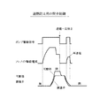
このため、上記特許文献1の技術を利用して、図6に示すように、高圧ポンプの開弁制御の際に、通常の開弁制御と同じタイミングでソレノイドへの通電を停止した後に、ソレノイドに一時的に再通電するようにしても、可動部が調量弁に突き当たって止まっているときに再通電する可能性がある。このような場合、その後、ポンプ室内の燃圧が低下して可動部が開側位置に移動する際の移動速度を低下させることができず、開弁制御時に発生する騒音を低減することが困難である。 For this reason, using the technique of the above-mentioned Patent Document 1, as shown in FIG. 6, after the energization to the solenoid is stopped at the same timing as the normal valve opening control in the valve opening control of the high-pressure pump, Even if the power is temporarily re-energized, there is a possibility that the power is re-energized when the movable part stops against the metering valve. In such a case, after that, the fuel pressure in the pump chamber decreases and the moving speed when the movable part moves to the open position cannot be reduced, and it is difficult to reduce the noise generated during valve opening control. is there.
そこで、本出願人は、図5に示すように、高圧ポンプの開弁制御の際に、ポンプ室内の燃圧が低下して調量弁が開弁するまでソレノイドへの通電を継続して可動部を閉側位置に保持し、調量弁が開弁した後にソレノイドへの通電を一旦停止して、可動部が開側位置に到達する前にソレノイドに一時的に再通電することで、開弁制御時に発生する騒音を低減するシステムを研究しているが、その研究過程で次のような新たな課題が判明した。 Therefore, as shown in FIG. 5, the applicant of the present invention, when performing valve opening control of the high pressure pump, continues energization of the solenoid until the fuel pressure in the pump chamber decreases and the metering valve opens, thereby moving the movable part. Is held in the closed position, the energization to the solenoid is temporarily stopped after the metering valve is opened, and the solenoid is temporarily re-energized before the movable part reaches the open position. We are researching a system that reduces noise generated during control, and the following new problems were found in the research process.
上述した高圧ポンプの開弁制御の際に、可動部を閉側位置に保持する期間(つまりソレノイドへの通電を継続する期間)を長くし過ぎると、ソレノイドの発熱量が許容値を越えてソレノイドが過熱状態となる可能性がある。そこで、ソレノイドの過熱を防止するために、可動部を閉側位置に保持する期間を所定の上限ガード値で制限することが考えられる。しかし、この方法では、ソレノイドの発熱量が許容値以下で可動部を閉側位置に保持する期間を短くする必要が無いにも拘らず、可動部を閉側位置に保持する期間が上限ガード値で制限されてしまうことがある。このため、可動部を閉側位置に保持する期間を無駄に短くして、騒音低減効果を無駄に減少させてしまう可能性がある。 During the valve opening control of the high pressure pump described above, if the period during which the movable part is held at the closed position (that is, the period during which the solenoid is energized) is too long, the amount of heat generated by the solenoid exceeds the allowable value and the solenoid May become overheated. Therefore, in order to prevent overheating of the solenoid, it is conceivable to limit the period during which the movable part is held at the closed position by a predetermined upper limit guard value. However, in this method, the period during which the movable part is held at the closed position is not limited to the upper limit guard value although the amount of heat generated by the solenoid is less than the allowable value and there is no need to shorten the period during which the movable part is held at the closed position. May be limited. For this reason, there is a possibility that the period during which the movable part is held at the closed position is unnecessarily shortened and the noise reduction effect is unnecessarily reduced.
そこで、本発明が解決しようとする課題は、高圧ポンプの開弁制御時の騒音低減効果を無駄に減少させることなくソレノイドの過熱を防止することができる高圧ポンプの制御装置を提供することにある。 Therefore, the problem to be solved by the present invention is to provide a control device for a high pressure pump that can prevent solenoid overheating without unnecessarily reducing the noise reduction effect during valve opening control of the high pressure pump. .
上記課題を解決するために、請求項1に係る発明は、燃料の吸入口(21)と吐出口(31)を有するポンプ室(17)と、該ポンプ室(17)内で往復運動するプランジャ(18)と、前記吸入口(21)側を開閉する調量弁(23)と、該調量弁(23)を開閉移動させる電磁アクチュエータ(27)とを備えた高圧ポンプの制御装置において、
前記電磁アクチュエータ(27)のソレノイド(30)への通電を停止して該電磁アクチュエータ(27)の可動部(28)を閉側位置から開側位置に移動させると共に前記調量弁(23)を開弁させる開弁制御を実行する開弁制御手段(40)を備え、前記開弁制御手段は、前記開弁制御の際に、前記ソレノイドの発熱量を推定し、推定した前記発熱量が許容値以下の場合には、前記ポンプ室内の燃圧が低下して前記調量弁が開弁する後まで前記ソレノイドへの通電を継続して前記可動部を閉側位置に保持し、前記調量弁が開弁した後に前記ソレノイドへの通電を一旦停止することで、前記可動部を閉側位置に保持する期間を延長し、前記可動部が開側位置に到達する前に前記ソレノイドに一時的に再通電し、推定した前記発熱量が許容値を超える場合には、前記ポンプ室内の燃圧が低下して前記調量弁が開弁する前まで前記ソレノイドへの通電を継続して前記可動部を閉側位置に保持すると共に、前記調量弁が開弁する前に前記ソレノイドへの通電を一旦停止することで、推定した前記発熱量に応じて前記可動部を前記閉側位置に保持する期間を変更し、前記可動部が開側位置に到達する前に前記ソレノイドに一時的に再通電するようにしたものである。
In order to solve the above-mentioned problem, the invention according to claim 1 is directed to a pump chamber (17) having a fuel inlet (21) and a discharge port (31), and a plunger that reciprocates in the pump chamber (17). (18) a control device for a high-pressure pump comprising: a metering valve (23) for opening and closing the suction port (21); and an electromagnetic actuator (27) for opening and closing the metering valve (23).
The energization of the solenoid (30) of the electromagnetic actuator (27) is stopped to move the movable part (28) of the electromagnetic actuator (27) from the closed position to the open position, and the metering valve (23) is moved. The valve opening control means (40) for performing valve opening control for opening the valve is provided, and the valve opening control means estimates the heat generation amount of the solenoid during the valve opening control, and the estimated heat generation amount is allowable. If the value or less, the fuel pressure in the pump chamber continues to energization of the solenoid until after you the metering valve is opened valves lowered to hold the movable part in the closed side position, the metering by temporarily stopping the energization of the solenoid after the valve is opened valves, and extend the period for holding the movable part in the closed side position, the solenoid before the movable portion reaches the open side position Temporarily re-energize and the estimated calorific value is an acceptable value. When it exceeds holds the movable portion to continue energization of the solenoid in front until the fuel pressure in the pump chamber is the metering valve is opened valve decreases the closing side position, the metering valve By temporarily stopping energization of the solenoid before the valve opens, the period during which the movable part is held at the closed position is changed according to the estimated heat generation amount, and the movable part is moved to the open position. The solenoid is temporarily re-energized before reaching .
この構成では、開弁制御の際に、ソレノイドの推定発熱量が小さいときには、可動部を閉側位置に保持する期間を適度に長くして、騒音低減効果を確保することができる。一方、ソレノイドの推定発熱量が大きいときには、可動部を閉側位置に保持する期間(つまりソレノイドへの通電を継続する期間)を短くして、ソレノイドの過熱を防止することができる。これにより、可動部を閉側位置に保持する期間を短くしてソレノイドの過熱を防止する必要があるときだけ、可動部を閉側位置に保持する期間を短くするようにできるため、可動部を閉側位置に保持する期間を無駄に短くすることを防止して、騒音低減効果を無駄に減少させることを回避することができる。 In this configuration, when the estimated heat generation amount of the solenoid is small during the valve opening control, the period during which the movable part is held in the closed position can be lengthened appropriately to ensure the noise reduction effect. On the other hand, when the estimated calorific value of the solenoid is large, the period during which the movable portion is held at the closed position (that is, the period during which energization of the solenoid is continued) can be shortened to prevent overheating of the solenoid. As a result, only when it is necessary to shorten the period for holding the movable part in the closed position to prevent the solenoid from overheating, the period for holding the movable part in the closed position can be shortened. It is possible to prevent the noise reduction effect from being unnecessarily reduced by preventing the period for holding the closed side position from being unnecessarily shortened.
以下、本発明を実施するための形態を具体化した一実施例を説明する。
図1に示すように、燃料を貯溜する燃料タンク11内には、燃料を汲み上げる低圧ポンプ12が設置されている。この低圧ポンプ12は、バッテリ(図示せず)を電源とする電動モータ(図示せず)によって駆動される。この低圧ポンプ12から吐出される燃料は、燃料配管13を通して高圧ポンプ14に供給される。燃料配管13には、プレッシャレギュレータ15が接続され、このプレッシャレギュレータ15によって低圧ポンプ12の吐出圧力(高圧ポンプ14への燃料供給圧力)が所定圧力に調圧され、その圧力を越える燃料の余剰分が燃料戻し配管16により燃料タンク11内に戻されるようになっている。
Hereinafter, an embodiment embodying a mode for carrying out the present invention will be described.
As shown in FIG. 1, a low-
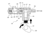
図2及び図3に示すように、高圧ポンプ14は、円筒状のポンプ室17内でプランジャ18を往復運動させて燃料を吸入/吐出するプランジャポンプであり、プランジャ18は、エンジンのカム軸19に嵌着されたカム20の回転運動によって駆動される。この高圧ポンプ14の吸入口21側には、燃料通路22を開閉する調量弁23と、この調量弁23を開閉移動させる電磁アクチュエータ27が設けられている。
As shown in FIGS. 2 and 3, the high-
電磁アクチュエータ27は、移動可能な可動部28と、この可動部28を開側位置(図2参照)へ付勢するスプリング29と、可動部28を閉側位置(図3参照)へ電磁駆動するソレノイド30(コイル)等で構成されている。調量弁23は、電磁アクチュエータ27の可動部28により開弁方向に押圧される押圧部24と、燃料通路22を開閉する弁体25と、この弁体25を閉弁方向に付勢するスプリング26等で構成されている。また、高圧ポンプ14の吐出口31側には、吐出した燃料の逆流を防止する逆止弁32が設けられている。
The
図2に示すように、電磁アクチュエータ27の非通電時(ソレノイド30への通電のオフ時)には、電磁アクチュエータ27のスプリング29の付勢力により可動部28が開側位置へ移動するため、可動部28により調量弁23の押圧部24が押圧されて弁体25が開弁方向に移動して開弁し、燃料通路22が開放される。
As shown in FIG. 2, when the
一方、図3に示すように、電磁アクチュエータ27の通電時(ソレノイド30への通電のオン時)には、電磁アクチュエータ27のソレノイド30の電磁吸引力により可動部28が閉側位置へ移動するため、調量弁23のスプリング26の付勢力により弁体25が閉弁方向に移動して閉弁し、燃料通路22が閉鎖される。
On the other hand, as shown in FIG. 3, when the
図2に示すように、高圧ポンプ14の吸入行程(プランジャ18の下降時)において調量弁23の弁体25が開弁してポンプ室17内に燃料が吸入され、図3に示すように、高圧ポンプ14の吐出行程(プランジャ18の上昇時)において調量弁23の弁体25が閉弁してポンプ室17内の燃料が吐出されるように電磁アクチュエータ27(ソレノイド30)の通電を制御する。
As shown in FIG. 2, the
その際、電磁アクチュエータ27(ソレノイド30)の通電開始時期を制御して調量弁23の閉弁期間を制御することで、高圧ポンプ14の燃料吐出量を制御して燃圧(燃料圧力)を制御する。例えば、燃圧を上昇させるときには、電磁アクチュエータ27の通電開始時期を進角させて調量弁23の閉弁開始時期を進角させることで、調量弁23の閉弁期間を長くして高圧ポンプ14の吐出流量を増加させる。逆に、燃圧を低下させるときには、電磁アクチュエータ27の通電開始時期を遅角させて調量弁23の閉弁開始時期を遅角させることで、調量弁23の閉弁期間を短くして高圧ポンプ14の吐出流量を減少させる。
At that time, by controlling the energization start timing of the electromagnetic actuator 27 (solenoid 30) and controlling the valve closing period of the
図1に示すように、高圧ポンプ14から吐出された燃料は、高圧燃料配管33を通してデリバリパイプ34に送られ、このデリバリパイプ34からエンジンの各気筒に取り付けられた燃料噴射弁35に高圧の燃料が分配される。デリバリパイプ34(又は高圧燃料配管33)には、高圧燃料配管33やデリバリパイプ34等の高圧燃料通路内の燃圧を検出する燃圧センサ36が設けられている。
As shown in FIG. 1, the fuel discharged from the high-
また、エンジンには、吸入空気量を検出するエアフローメータ37や、クランク軸(図示せず)の回転に同期して所定のクランク角毎にパルス信号を出力するクランク角センサ38が設けられている。このクランク角センサ38の出力信号に基づいてクランク角やエンジン回転速度が検出される。更に、エンジンのシリンダブロックには、冷却水温(冷却水の温度)を検出する冷却水温センサ39が設けられている。
Further, the engine is provided with an
これら各種センサの出力は、電子制御ユニット(以下「ECU」と表記する)40に入力される。このECU40は、マイクロコンピュータを主体として構成され、内蔵されたROM(記憶媒体)に記憶された各種のエンジン制御用のプログラムを実行することで、エンジン運転状態に応じて、燃料噴射量、点火時期、スロットル開度(吸入空気量)等を制御する。
Outputs of these various sensors are input to an electronic control unit (hereinafter referred to as “ECU”) 40. The
また、ECU40は、図4に示すように、高圧ポンプ14の調量弁23を閉弁させる閉弁制御の際には、電磁アクチュエータ27のソレノイド30に通電して電磁アクチュエータ27の可動部28を開側位置から閉側位置に移動させることで調量弁23を閉弁させる。その後、高圧ポンプ14の調量弁23を開弁させる開弁制御の際には、電磁アクチュエータ27のソレノイド30への通電を停止して電磁アクチュエータ27の可動部28を閉側位置から開側位置に移動させて調量弁23を開弁させる。
Further, as shown in FIG. 4, the
しかし、高圧ポンプ14の開弁制御時には、可動部28や調量弁23がストッパ部41等に衝突して振動が発生し、この振動によって不快な騒音が発生する可能性があり、例えば、低速走行中や停車中は、開弁制御時に発生する騒音が運転者に聞こえ易くなる。
However, during valve opening control of the high-
ところで、図4に示すように、高圧ポンプ14の開弁制御の際には、ソレノイド30への通電を停止しても、まだポンプ室17内の燃圧が高いときには、可動部28が調量弁23(押圧部24)に突き当たってもポンプ室17内の燃圧で調量弁23が閉弁状態に維持されるため、可動部28が調量弁23(押圧部24)に突き当たった状態で止まる。その後、ポンプ室17内の燃圧が低下すると、可動部28が開側位置に移動すると共に調量弁23が開弁する。
By the way, as shown in FIG. 4, in the valve opening control of the
このため、従来技術を利用して、図6に示す比較例のように、高圧ポンプ14の開弁制御の際に、通常の開弁制御と同じタイミングでソレノイド30への通電を停止した後に、ソレノイド30に一時的に再通電するようにしても、可動部28が調量弁23(押圧部24)に突き当たって止まっているときに再通電する可能性がある。このような場合、その後、ポンプ室17内の燃圧が低下して可動部28が開側位置に移動する際の移動速度を低下させることができず、開弁制御時に発生する騒音を低減することが困難である。
For this reason, using the conventional technology, as in the comparative example shown in FIG. 6, after the energization of the
そこで、本実施例では、ECU40により後述する図17及び図18の開弁制御用の各ルーチンを実行することで、開弁制御の際(つまり電磁アクチュエータ27のソレノイド30への通電を停止して可動部28を閉側位置から開側位置に移動させると共に調量弁23を開弁させる際)に、所定の音低減制御実行条件が成立したときには、開弁制御時に発生する騒音が運転者に聞こえ易い状態であると判断して、開弁制御時に発生する騒音を低減するために、後述するソレノイド30の推定発熱量が許容値以下であれば、図5に示すように、音低減用の開弁制御を実行する。この音低減用の開弁制御では、ポンプ室17内の燃圧が低下して調量弁23が開弁する後までソレノイド30への通電を継続して可動部28を閉側位置に保持し、調量弁23が開弁した後にソレノイドへ30の通電を一旦停止する。これにより、可動部28が調量弁23に突き当たって止まることなく開側位置へ向かって移動する。そして、可動部28が開側位置に到達する前にソレノイド30に一時的に再通電する。これにより、ソレノイド30の電磁吸引力を一時的に発生させて、この電磁吸引力により可動部28が開側位置に移動する際の移動速度を低下させることができる。これにより、可動部28が開側位置に到達する際に発生する振動を抑制することができ、開弁制御時に発生する騒音を低減することができる。
Accordingly, in this embodiment, the
この音低減用の開弁制御では、ポンプ室17内の燃圧が所定値(調量弁23が開弁する燃圧)以下に低下して調量弁23が開弁するまでソレノイド30への通電を継続して可動部28を閉側位置に保持する必要がある。
In this valve opening control for reducing noise, the
ここで、カムリフト量L(プランジャ18のリフト量)とポンプ室17内の燃圧Pとの関係は、ポンプ室17の容積Vと、燃料の体積弾性率Eと、プランジャ18の面積Sとを用いて、下記(1)式で表すことができる。
L=P×V/(E×S) …(1)
Here, the relationship between the cam lift amount L (the lift amount of the plunger 18) and the fuel pressure P in the
L = P × V / (E × S) (1)
上記(1)式より、ポンプ室17内の燃圧Pが高くなるほど、その燃圧Pを所定値以下に低下させるのに必要なカムリフト量Lの降下分が大きくなるため、燃圧Pが所定値以下に低下するまでの期間が長くなる。
From the above equation (1), as the fuel pressure P in the
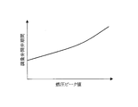
このため、図7に示すように、ポンプ室17内の燃圧ピーク値が高くなるほど、燃圧が所定値(調量弁23が開弁する燃圧)以下に低下するまでの期間が長くなって、調量弁開弁期間(燃圧が低下し始めてから調量弁23が開弁するまでの期間)が長くなる。つまり、図8に示すように、ポンプ室17内の燃圧ピーク値が高くなるほど、調量弁開弁期間が長くなるという特性がある。
For this reason, as shown in FIG. 7, as the fuel pressure peak value in the
そこで、本実施例では、音低減用の開弁制御の際に、ポンプ室17内の燃圧ピーク値に応じて、可動部28を閉側位置に保持する期間を変更する。具体的には、ポンプ室17内の燃圧ピーク値が高くなるほど、通電延長期間(通常の開弁制御の通電停止タイミングに対してソレノイド30への通電を延長する期間)を長くして、可動部28を閉側位置に保持する期間を長くする。このようにすれば、ポンプ室17内の燃圧ピーク値に応じて、調量弁開弁期間が変化するのに対応して、可動部28を閉側位置に保持する期間を変更することができる。これにより、燃圧ピーク値の変化によって調量弁開弁期間が変化しても、調量弁23が開弁するまで確実に可動部28を閉側位置に保持するようにできる。
Therefore, in this embodiment, during the valve opening control for sound reduction, the period during which the
また、図9に示すように、燃料温度が高くなるほど、燃料の体積弾性率が小さくなる。更に、上記(1)式より、燃料の体積弾性率Eが小さくなるほど、燃圧Pを所定値以下に低下させるのに必要なカムリフト量Lの降下分が大きくなるため、燃圧Pが所定値以下に低下するまでの期間が長くなる(つまり調量弁開弁期間が長くなる)。このため、図10に示すように、燃料温度が高くなるほど、調量弁開弁期間が長くなるという特性がある。 Moreover, as shown in FIG. 9, the higher the fuel temperature, the smaller the volume elastic modulus of the fuel. Furthermore, from the above equation (1), as the volume elastic modulus E of the fuel decreases, the amount of decrease in the cam lift amount L required to lower the fuel pressure P to a predetermined value or greater increases, so the fuel pressure P decreases to a predetermined value or less. The period until it decreases becomes longer (that is, the metering valve opening period becomes longer). For this reason, as shown in FIG. 10, there is a characteristic that the metering valve opening period becomes longer as the fuel temperature becomes higher.
そこで、本実施例では、音低減用の開弁制御の際に、燃料温度に応じて、可動部28を閉側位置に保持する期間を変更する。具体的には、燃料温度が高くなるほど、通電延長期間を長くして、可動部28を閉側位置に保持する期間を長くする。このようにすれば、燃料温度に応じて、調量弁開弁期間が変化するのに対応して、可動部28を閉側位置に保持する期間を変更することができる。これにより、燃料温度の変化によって調量弁開弁期間が変化しても、調量弁23が開弁するまで確実に可動部28を閉側位置に保持するようにできる。尚、燃料温度は温度センサで検出するようにしても良いが、燃料温度の代用情報として、冷却水温や油温等を用いるようにしても良い。或は、冷却水温や油温等に基づいて燃料温度を推定するようにしても良い。
Therefore, in the present embodiment, during valve opening control for sound reduction, the period during which the
また、図11に示すように、カムプロフィール(カム20の形状)の違いによって、カムリフト量の降下速度が異なってくる。更に、図12に示すように、カムリフト量の降下速度が速くなるほど、調量弁開弁期間が短くなる。つまり、カムプロフィールに応じて、調量弁開弁期間が変化する。 Moreover, as shown in FIG. 11, the descending speed of the cam lift amount varies depending on the cam profile (the shape of the cam 20). Furthermore, as shown in FIG. 12, the metering valve opening period is shortened as the cam lift amount descending speed increases. That is, the metering valve opening period changes according to the cam profile.
そこで、本実施例では、カムプロフィールに応じて、可動部28を閉側位置に保持する期間を変更する。具体的には、カムプロフィールの違いによってカムリフト量の降下速度が速くなるほど、通電延長期間を短くして、可動部28を閉側位置に保持する期間を短くする。このようにすれば、カムプロフィールに応じて、調量弁開弁期間が変化するのに対応して、可動部28を閉側位置に保持する期間を変更することができる。これにより、カムプロフィールの違いによって調量弁開弁期間が変化しても、調量弁23が開弁するまで確実に可動部28を閉側位置に保持するようにできる。
Therefore, in this embodiment, the period during which the
また、「通電延長期間」を「時間」で設定する場合、カム20の回転速度に応じて、調量弁開弁期間(時間)が変化するため、カム20の回転速度に応じて、通電延長期間(時間)を変更して、可動部28を閉側位置に保持する期間(時間)を変更する。このようにすれば、カム20の回転速度に応じて、調量弁開弁期間(時間)が変化するのに対応して、可動部28を閉側位置に保持する期間(時間)を変更することができる。これにより、カム20の回転速度の変化によって調量弁開弁期間(時間)が変化しても、調量弁23が開弁するまで確実に可動部28を閉側位置に保持するようにできる。
尚、「通電延長期間」を「カム角又はクランク角」で設定する場合には、カム20の回転速度の影響を受けないため、カム20の回転速度に応じた変更を行う必要がない。
Further, when the “energization extension period” is set as “time”, the metering valve opening period (time) changes according to the rotation speed of the
When the “energization extension period” is set as “cam angle or crank angle”, it is not affected by the rotational speed of the
また、本実施例では、音低減用の開弁制御の際に、可動部28が開側位置に到達する前にソレノイド30に一時的に再通電するようにしているが、図13(b)に示すように、再通電するときの電流値が大き過ぎると、ソレノイド30の電磁吸引力が大きくなり過ぎて、可動部28が閉側位置方向へ逆戻りしてしまう可能性がある。
Further, in this embodiment, during the valve opening control for sound reduction, the
そこで、本実施例では、図13(a)に示すように、再通電するときの電流値を、可動部28の閉側位置方向への逆戻りが発生しない範囲内で設定する。このようにすれば、可動部28が開側位置に到達する前にソレノイド30に一時的に再通電したときに、可動部28が閉側位置方向へ逆戻りすることを防止することができる。
Therefore, in this embodiment, as shown in FIG. 13A, the current value at the time of re-energization is set within a range in which the backward movement of the
また、本実施例では、音低減用の開弁制御の際に、調量弁23が開弁した後にソレノイド30への通電を一旦停止するようにしているが、図14(b)に示すように、後述するフライバック制御を実行しない場合には、ソレノイド30への通電を一旦停止したときに、逆起電力によりソレノイド30に流れる電流がゆっくりと低下する。このため、ソレノイド30への通電停止後もソレノイド30の電磁吸引力が発生し、その影響を受けて可動部28が開側位置に移動する際の挙動がばらついて、再通電するタイミングを設定するのが困難になる。
Further, in this embodiment, during the valve opening control for sound reduction, energization to the
そこで、本実施例では、図14(a)に示すように、ソレノイド30への通電を一旦停止したときに逆起電力によりソレノイド30に流れる電流をフライバック回路(図示せず)により取り去るフライバック制御を実行する。このようにすれば、ソレノイド30への通電停止後にソレノイド30の電磁吸引力がほとんど発生せず、可動部28が開側位置に移動する際の挙動が安定するため、再通電するタイミングを容易に設定することができる。
Therefore, in this embodiment, as shown in FIG. 14A, the flyback circuit removes the current flowing through the
上述した高圧ポンプ14の開弁制御の際に、可動部28を閉側位置に保持する期間(つまりソレノイド30への通電を継続する期間)を長くし過ぎると、ソレノイド30の発熱量が許容値を越えてソレノイド30が過熱状態となる可能性がある。そこで、ソレノイド30の過熱を防止するために、可動部28を閉側位置に保持する期間を所定の上限ガード値で制限することが考えられる。しかし、この方法では、ソレノイド30の発熱量が許容値以下で可動部28を閉側位置に保持する期間を短くする必要が無いにも拘らず、可動部28を閉側位置に保持する期間が上限ガード値で制限されてしまうことがある。このため、可動部28を閉側位置に保持する期間を無駄に短くして、騒音低減効果を無駄に減少させてしまう可能性がある。
In the valve opening control of the high-
そこで、本実施例では、高圧ポンプ14の開弁制御の際に、ソレノイド30の発熱量を推定(算出)し、そのソレノイド30の推定発熱量に応じて可動部28を閉側位置に保持する期間を変更する。これにより、ソレノイド30の推定発熱量が小さいときには、可動部28を閉側位置に保持する期間を適度に長くして、騒音低減効果を確保する。一方、ソレノイド30の推定発熱量が大きいときには、可動部28を閉側位置に保持する期間(つまりソレノイド30への通電を継続する期間)を短くして、ソレノイド30の過熱を防止する。
Therefore, in this embodiment, the heat generation amount of the
具体的には、ソレノイド30の推定発熱量が許容値以下の場合には、図15に示すように、前述した音低減用の開弁制御を実行する。この音低減用の開弁制御では、ポンプ室17内の燃圧が低下して調量弁23が開弁する後までソレノイド30への通電を継続して可動部28を閉側位置に保持し、調量弁23が開弁した後にソレノイド30への通電を一旦停止することで、可動部28を閉側位置に保持する期間を適度に長くして、可動部28が開側位置に到達する前にソレノイド30に一時的に再通電する。
Specifically, when the estimated heat generation amount of the
一方、ソレノイド30の推定発熱量が許容値を越える場合には、図16に示すように、過熱防止用の開弁制御を実行する。この過熱防止用の開弁制御では、ポンプ室17内の燃圧が低下して調量弁23が開弁する前までソレノイド30への通電を継続して可動部28を閉側位置に保持し、調量弁23が開弁する前にソレノイド30への通電を一旦停止することで、可動部28を閉側位置に保持する期間を短くして、ソレノイド30の過熱を防止する。この場合、通常の開弁制御(図4参照)と同じように、可動部28が調量弁23(押圧部24)に突き当たった状態で止まり、その後、ポンプ室17内の燃圧が低下すると、可動部28が開側位置に移動すると共に調量弁23が開弁するが、過熱防止用の開弁制御では、可動部28が開側位置に到達する前にソレノイド30に一時的に再通電する。これにより、可動部28が開側位置に到達する際に発生する振動を抑制することができ、開弁制御時に発生する騒音を低減することができる。
On the other hand, when the estimated heat generation amount of the
本実施例では、過熱防止用の開弁制御の際に、通常の開弁制御(図4参照)の通電停止タイミングに対してソレノイド30への通電を延長する期間である通電延長期間(図5参照)を0にして、通常の開弁制御の通電停止タイミングと同じタイミング(例えばカムリフト量が最大となるカムTOP又はそれよりも進角側のタイミング)でソレノイド30への通電を一旦停止することで、可動部28を閉側位置に保持する期間を短くする。
In the present embodiment, during the valve opening control for preventing overheating, the energization extension period (FIG. 5), which is the period for extending the energization to the
また、前述したように、図8に示すように、ポンプ室17内の燃圧ピーク値が高くなるほど、調量弁開弁期間(燃圧が低下し始めてから調量弁23が開弁するまでの期間)が長くなるという特性がある。
Further, as described above, as shown in FIG. 8, as the fuel pressure peak value in the
そこで、本実施例では、過熱防止用の開弁制御の際に、ポンプ室17内の燃圧ピーク値に応じて、ソレノイド30に一時的に再通電するタイミングを変更する。具体的には、ポンプ室17内の燃圧ピーク値が高くなるほど、ソレノイド30に一時的に再通電するタイミングを遅くする。このようにすれば、ポンプ室17内の燃圧ピーク値に応じて、調量弁開弁期間が変化するのに対応して、ソレノイド30に一時的に再通電するタイミングを変更することができる。これにより、燃圧ピーク値の変化によって調量弁開弁期間が変化しても、調量弁23が開弁すると共に可動部28が開側位置に到達する前に確実にソレノイド30に再通電することができる。
Therefore, in the present embodiment, the timing for temporarily re-energizing the
以上説明した本実施例の高圧ポンプ14の開弁制御は、ECU40によって図17及び図18の開弁制御用の各ルーチンに従って実行される。以下、これらの各ルーチンの処理内容を説明する。
The valve opening control of the high-
[開弁制御ルーチン]
図17に示す開弁制御ルーチンは、ECU40の電源オン期間中(イグニッションスイッチのオン期間中)に所定周期で繰り返し実行され、特許請求の範囲でいう開弁制御手段としての役割を果たす。本ルーチンが起動されると、まず、ステップ101で、所定の音低減制御実行条件が成立しているか否かを、例えば、次の(1) 〜(5) の条件を全て満たすか否かによって判定する。
[Valve opening control routine]
The valve opening control routine shown in FIG. 17 is repeatedly executed at a predetermined period during the power-on period of the ECU 40 (while the ignition switch is on), and serves as valve opening control means in the claims. When this routine is started, first, in
(1) バッテリ電圧が安定状態(バッテリ電圧>所定値)であること
(2) 低速走行中又は停車中(車速≦所定値)であること
(3) アクセルオフ(アクセル開度=0)であること
(4) エンジン回転速度が安定状態(|目標回転速度−エンジン回転速度|≦所定値)であること
(5) 燃圧が安定状態(|目標燃圧−燃圧|≦所定値)であること
(1) Battery voltage is stable (battery voltage> predetermined value)
(2) Running at low speed or stopping (vehicle speed ≤ predetermined value)
(3) Accelerator off (accelerator opening = 0)
(4) The engine speed is in a stable state (| target speed-engine speed | ≦ predetermined value)
(5) The fuel pressure is in a stable state (| target fuel pressure – fuel pressure | ≦ predetermined value)
ここで、上記(2) と(3) の条件は、開弁制御時に発生する騒音が運転者に聞こえ易い状態であるか否かを判断するための条件である。
上記(1) 〜(5) の条件を全て満たせば、音低減制御実行条件が成立するが、上記(1) 〜(5) の条件のうちのいずれか1つでも満たさない条件があれば、音低減制御実行条件が不成立となる。
Here, the above conditions (2) and (3) are conditions for determining whether or not the noise generated during the valve opening control is easily heard by the driver.
If all of the above conditions (1) to (5) are satisfied, the sound reduction control execution condition is satisfied, but if there is a condition that does not satisfy any one of the above conditions (1) to (5), The sound reduction control execution condition is not satisfied.
このステップ101で、音低減制御実行条件が不成立と判定された場合には、ステップ102に進み、通常の開弁制御(図4参照)を実行する。この通常の開弁制御では、ポンプ室17内の燃圧が高くなったときに電磁アクチュエータ27のソレノイド30への通電を停止する。この場合、ポンプ室17内の燃圧で調量弁23が閉弁状態に維持されるため、可動部28が調量弁23(押圧部24)に突き当たった状態で止まるが、その後、ポンプ室17内の燃圧が低下すると、可動部28が開側位置に移動すると共に調量弁23が開弁する。
If it is determined in
一方、上記ステップ101で、音低減制御実行条件が成立していると判定された場合には、開弁制御時に発生する騒音が運転者に聞こえ易い状態であると判断して、音低減用の開弁制御(又は過熱防止用の開弁制御)を次のようにして実行する。まず、ステップ103で、通常の開弁制御の通電停止タイミングに対してソレノイド30への通電を延長する期間である「通電延長期間(図5参照)」を「カム角又はクランク角」で設定する。このステップ103で設定される通電延長期間は、音低減用の開弁制御のための通電延長期間(つまり調量弁23が開弁する後までソレノイド30への通電を継続するための通電延長期間)である。
On the other hand, if it is determined in
この場合、まず、ポンプ室17内の燃圧ピーク値に応じた通電延長期間をマップ又は数式等により算出する。これにより、ポンプ室17内の燃圧ピーク値が高くなるほど、通電延長期間を長くして、可動部28を閉側位置に保持する期間を長くする。通電延長期間のマップ又は数式等は、予め試験データや設計データ等に基づいて作成され、ECU40のROMに記憶されている。
In this case, first, the energization extension period corresponding to the fuel pressure peak value in the
また、燃料温度に応じた補正値をマップ又は数式等により算出し、この補正値を用いて通電延長期間を補正する。これにより、燃料温度が高くなるほど、通電延長期間を長くして、可動部28を閉側位置に保持する期間を長くする。更に、カムプロフィールに応じた補正値をマップ又は数式等により算出し、この補正値を用いて通電延長期間を補正するようにしても良い。これにより、カムプロフィールの違いによってカムリフト量の降下速度が速くなるほど、通電延長期間を短くして、可動部28を閉側位置に保持する期間を短くする。通電延長期間の補正値のマップ又は数式等は、予め試験データや設計データ等に基づいて作成され、ECU40のROMに記憶されている。
Further, a correction value corresponding to the fuel temperature is calculated using a map or a mathematical formula, and the energization extension period is corrected using this correction value. As a result, the higher the fuel temperature, the longer the energization extension period and the longer the period for holding the
尚、「通電延長期間」を「時間」で設定する場合には、カム20の回転速度に応じて、調量弁開弁期間(時間)が変化するため、カム20の回転速度に応じて、通電延長期間(時間)を変更して、可動部28を閉側位置に保持する期間(時間)を変更する。
When the “energization extension period” is set as “time”, the metering valve opening period (time) changes according to the rotation speed of the
この後、ステップ104に進み、ソレノイド30への通電を一旦停止してから再通電するまでの時間である「通電停止時間(図5参照)」を所定時間T1 (例えば0.5ms)に設定し、ソレノイド30への再通電を継続する時間である「再通電時間(図5参照)」を所定時間T2 (例えば1ms)に設定すると共に、ソレノイド30に再通電するときの電流値である「再通電電流値(図5参照)」を所定電流値(例えば3A)に設定する。これらの所定時間T1 、所定時間T2 、所定電流値は、予め試験データや設計データ等に基づいて設定され、ECU40のROMに記憶されている。このステップ104で設定される通電停止時間は、音低減用の開弁制御のための通電停止時間である。
Thereafter, the routine proceeds to step 104, where the “energization stop time (see FIG. 5)”, which is the time from when power supply to the
この後、ステップ105に進み、後述する図18の条件変更ルーチンを実行することで、ソレノイド30の発熱量を推定(算出)し、そのソレノイド30の推定発熱量に基づいて通電延長期間や通電停止時間を変更する。
Thereafter, the routine proceeds to step 105, where a calorific value of the
この後、ステップ106に進み、通電延長期間が終了するまでソレノイド30への通電を継続することで、ポンプ室17内の燃圧が低下して調量弁23が開弁する前か後までソレノイド30への通電を継続して可動部28を閉側位置に保持する。
Thereafter, the process proceeds to step 106, and energization to the
この後、ステップ107に進み、上記ステップ103で設定した通電延長期間(又は上記ステップ105で変更した通電延長期間)が終了した時点で、ソレノイドへ30の通電を一旦停止すると共に、ソレノイド30に流れる電流をフライバック回路により取り去るフライバック制御を実行する。
Thereafter, the process proceeds to step 107, and when the energization extension period set in step 103 (or the energization extension period changed in step 105) ends, the energization of the
この後、ステップ108に進み、上記ステップ104で設定した通電停止時間(又は上記ステップ105で変更した通電停止時間)が経過した時点で、上記ステップ104で設定した再通電時間と再通電電流値でソレノイド30に再通電することで、可動部28が開側位置に到達する前にソレノイド30に一時的に再通電する。これにより、ソレノイド30の電磁吸引力を一時的に発生させて、この電磁吸引力により可動部28が開側位置に移動する際の移動速度を低下させる。
Thereafter, the process proceeds to step 108, and when the energization stop time set in step 104 (or the energization stop time changed in step 105) elapses, the re-energization time and re-energization current value set in
[条件変更ルーチン]
図18に示す条件変更ルーチンは、前記図17の開弁制御ルーチンのステップ105で実行されるサブルーチンである。本ルーチンが起動されると、まず、ステップ201で、ソレノイド30の発熱量の挙動を模擬した発熱量モデルを用いて、ソレノイド30の通電期間と、ソレノイド30の通電電流値(例えばピーク電流値や平均電流値等)と、高圧ポンプ14の温度に関する情報(例えば冷却水温や油温等)と、高圧ポンプ14の駆動速度に関する情報(例えばエンジン回転速度やポンプ回転速度等)に基づいてソレノイド30の推定発熱量を算出する。これにより、ソレノイド30の推定発熱量を精度良く算出することができる。ソレノイド30の発熱量モデルは、予め試験データや設計データ等に基づいて作成され、ECU40のROMに記憶されている。
[Condition change routine]
The condition change routine shown in FIG. 18 is a subroutine executed in
この後、ステップ202に進み、ソレノイド30の推定発熱量が許容値を越えているか否かを判定する。このステップ202で、ソレノイド30の推定発熱量が許容値以下であると判定された場合には、可動部28を閉側位置に保持する期間(つまりソレノイド30への通電を継続する期間)を短くする必要がないと判断して、ステップ203に進み、通電延長期間を図17のステップ103で設定された通電延長期間(音低減用の開弁制御のための通電延長期間)に保持すると共に、通電停止時間を図17のステップ104で設定された通電停止時間(音低減用の開弁制御のための通電停止時間)に保持する。これにより、図17のステップ106〜108では音低減用の開弁制御が実行される。
Thereafter, the routine proceeds to step 202, where it is determined whether or not the estimated heat generation amount of the
一方、上記ステップ202で、ソレノイド30の推定発熱量が許容値を越えていると判定された場合には、可動部28を閉側位置に保持する期間(つまりソレノイド30への通電を継続する期間)を短くする必要があると判断して、ステップ204に進み、通電延長期間を過熱防止用の開弁制御のための通電延長期間に変更すると共に、通電停止時間を過熱防止用の開弁制御のための通電停止時間に変更する。これにより、図17のステップ106〜108では過熱防止用の開弁制御が実行される。
On the other hand, if it is determined in
具体的には、通電延長期間を所定値(例えば0)に設定すると共に、ポンプ室17内の燃圧ピーク値に応じた通電停止時間をマップ又は数式等により算出する。これにより、ポンプ室17内の燃圧ピーク値が高くなるほど、通電停止時間を長くして、ソレノイド30に一時的に再通電するタイミングを遅くする。過熱防止用の開弁制御のための通電停止時間のマップ又は数式等は、予め試験データや設計データ等に基づいて作成され、ECU40のROMに記憶されている。
Specifically, the energization extension period is set to a predetermined value (for example, 0), and the energization stop time corresponding to the fuel pressure peak value in the
以上説明した本実施例では、高圧ポンプ14の開弁制御の際に、所定の音低減制御実行条件が成立したときには、ソレノイド30の発熱量を推定(算出)し、そのソレノイド30の推定発熱量が許容値以下の場合には、音低減用の開弁制御を実行する。この音低減用の開弁制御では、ポンプ室17内の燃圧が低下して調量弁23が開弁する後までソレノイド30への通電を継続して可動部28を閉側位置に保持し、調量弁23が開弁した後にソレノイドへ30の通電を一旦停止することで、可動部28を閉側位置に保持する期間を適度に長くして、可動部28が開側位置に到達する前にソレノイド30に一時的に再通電する。これにより、可動部28が開側位置に到達する際に発生する振動を抑制することができ、開弁制御時に発生する騒音を低減することができる。
In the present embodiment described above, the heat generation amount of the
一方、ソレノイド30の推定発熱量が許容値を越える場合には、過熱防止用の開弁制御を実行する。この過熱防止用の開弁制御では、ポンプ室17内の燃圧が低下して調量弁23が開弁する前までソレノイド30への通電を継続して可動部28を閉側位置に保持し、調量弁23が開弁する前にソレノイド30への通電を一旦停止することで、可動部28を閉側位置に保持する期間を短くして、ソレノイド30の過熱を防止する。この場合、可動部28が調量弁23(押圧部24)に突き当たった状態で止まり、その後、ポンプ室17内の燃圧が低下すると、可動部28が開側位置に移動すると共に調量弁23が開弁するが、可動部28が開側位置に到達する前にソレノイド30に一時的に再通電する。これにより、可動部28が開側位置に到達する際に発生する振動を抑制することができ、開弁制御時に発生する騒音を低減することができる。
On the other hand, when the estimated heat generation amount of the
このように、ソレノイド30の推定発熱量に応じて可動部28を閉側位置に保持する期間を変更することで、ソレノイド30の推定発熱量が小さいときには、可動部28を閉側位置に保持する期間を適度に長くして、騒音低減効果を確保することができ、一方、ソレノイド30の推定発熱量が大きいときには、可動部28を閉側位置に保持する期間(つまりソレノイド30への通電を継続する期間)を短くして、ソレノイド30の過熱を防止することができる。これにより、可動部28を閉側位置に保持する期間を短くしてソレノイド30の過熱を防止する必要があるときだけ、可動部28を閉側位置に保持する期間を短くするようにできるため、可動部28を閉側位置に保持する期間を無駄に短くすることを防止して、騒音低減効果を無駄に減少させることを回避することができる。
Thus, by changing the period during which the
尚、上記実施例では、ソレノイド30の推定発熱量が許容値を越えるか否かによって可動部28を閉側位置に保持する期間を切り換えるようにしたが、これに限定されず、例えば、ソレノイド30の推定発熱量に応じて可動部28を閉側位置に保持する期間を複数段階又は連続的に変化させるようにしても良い。
In the above embodiment, the period for holding the
その他、本発明は、高圧ポンプの構成や燃料供給システムの構成を適宜変更しても良い等、要旨を逸脱しない範囲内で種々変更して実施できる。 In addition, the present invention can be implemented with various modifications without departing from the gist, such as appropriately changing the configuration of the high-pressure pump and the configuration of the fuel supply system.
14…高圧ポンプ、17…ポンプ室、18…プランジャ、21…吸入口、23…調量弁、27…電磁アクチュエータ、28…可動部、30…ソレノイド、31…吐出口、40…ECU(開弁制御手段)
DESCRIPTION OF
Claims (4)
前記電磁アクチュエータ(27)のソレノイド(30)への通電を停止して該電磁アクチュエータ(27)の可動部(28)を閉側位置から開側位置に移動させると共に前記調量弁(23)を開弁させる開弁制御を実行する開弁制御手段(40)を備え、
前記開弁制御手段は、前記開弁制御の際に、前記ソレノイドの発熱量を推定し、
推定した前記発熱量が許容値以下の場合には、前記ポンプ室内の燃圧が低下して前記調量弁が開弁する後まで前記ソレノイドへの通電を継続して前記可動部を閉側位置に保持し、前記調量弁が開弁した後に前記ソレノイドへの通電を一旦停止することで、前記可動部を閉側位置に保持する期間を延長し、前記可動部が開側位置に到達する前に前記ソレノイドに一時的に再通電し、
推定した前記発熱量が許容値を超える場合には、前記ポンプ室内の燃圧が低下して前記調量弁が開弁する前まで前記ソレノイドへの通電を継続して前記可動部を閉側位置に保持すると共に、前記調量弁が開弁する前に前記ソレノイドへの通電を一旦停止することで、推定した前記発熱量に応じて前記可動部を前記閉側位置に保持する期間を変更し、前記可動部が開側位置に到達する前に前記ソレノイドに一時的に再通電する、高圧ポンプの制御装置。 A pump chamber (17) having a fuel suction port (21) and a discharge port (31), a plunger (18) reciprocating in the pump chamber (17), and a control for opening and closing the suction port (21) side. In a control device for a high-pressure pump comprising a quantity valve (23) and an electromagnetic actuator (27) for opening and closing the metering valve (23),
The energization of the solenoid (30) of the electromagnetic actuator (27) is stopped to move the movable part (28) of the electromagnetic actuator (27) from the closed position to the open position, and the metering valve (23) is moved. Comprising valve opening control means (40) for performing valve opening control for opening the valve;
The valve opening control means estimates the amount of heat generated by the solenoid during the valve opening control,
If the calorific value estimated is less than the allowable value, close side position the movable portion fuel pressure of the pump chamber continues to energization of the solenoid until after you the metering valve is opened valve decreases held in, by temporarily stopping the energization of the solenoid after the metering valve is opened valves, and extend the period for holding the movable part in the closed side position, the movable part is open-side position Temporarily re-energize the solenoid before reaching
When the calorific value estimated exceeds the allowable value, close side position the movable portion to continue energization of the solenoid in front until the fuel pressure in the pump chamber is the metering valve is opened valve decreases holds to, by the metering valve to temporarily stop the energization of the solenoid prior to opening, the movable part to change the length of time for holding the closed side position in accordance with the calorific value estimated A control device for a high-pressure pump , wherein the solenoid is temporarily re-energized before the movable part reaches the open position .
Priority Applications (3)
| Application Number | Priority Date | Filing Date | Title |
|---|---|---|---|
| JP2013015474A JP6044366B2 (en) | 2013-01-30 | 2013-01-30 | High pressure pump control device |
| PCT/JP2014/000429 WO2014119289A1 (en) | 2013-01-30 | 2014-01-28 | Control device for high-pressure pump |
| DE112014000612.2T DE112014000612B4 (en) | 2013-01-30 | 2014-01-28 | Control device for a high pressure pump |
Applications Claiming Priority (1)
| Application Number | Priority Date | Filing Date | Title |
|---|---|---|---|
| JP2013015474A JP6044366B2 (en) | 2013-01-30 | 2013-01-30 | High pressure pump control device |
Publications (2)
| Publication Number | Publication Date |
|---|---|
| JP2014145339A JP2014145339A (en) | 2014-08-14 |
| JP6044366B2 true JP6044366B2 (en) | 2016-12-14 |
Family
ID=51262007
Family Applications (1)
| Application Number | Title | Priority Date | Filing Date |
|---|---|---|---|
| JP2013015474A Active JP6044366B2 (en) | 2013-01-30 | 2013-01-30 | High pressure pump control device |
Country Status (3)
| Country | Link |
|---|---|
| JP (1) | JP6044366B2 (en) |
| DE (1) | DE112014000612B4 (en) |
| WO (1) | WO2014119289A1 (en) |
Families Citing this family (5)
| Publication number | Priority date | Publication date | Assignee | Title |
|---|---|---|---|---|
| JP6265091B2 (en) * | 2014-09-19 | 2018-01-24 | 株式会社デンソー | High pressure pump control device |
| US10557445B2 (en) | 2015-01-21 | 2020-02-11 | Hitachi Automotive Systems, Ltd | High-pressure fuel supply device for internal combustion engine |
| JP6464972B2 (en) | 2015-09-24 | 2019-02-06 | 株式会社デンソー | High pressure pump controller |
| JP6710045B2 (en) | 2015-12-25 | 2020-06-17 | 日立オートモティブシステムズ株式会社 | Control method of high-pressure fuel supply pump and high-pressure fuel supply pump using the same |
| DE102016216343A1 (en) * | 2016-08-30 | 2018-03-01 | Robert Bosch Gmbh | Method for controlling an electromagnetically controllable inlet valve |
Family Cites Families (8)
| Publication number | Priority date | Publication date | Assignee | Title |
|---|---|---|---|---|
| JPH04153542A (en) * | 1990-10-12 | 1992-05-27 | Nippondenso Co Ltd | Solenoid valve driving device |
| DE10148218B4 (en) * | 2001-09-28 | 2005-08-25 | Robert Bosch Gmbh | Method for operating an internal combustion engine, computer program, control and / or regulating device, and fuel system for an internal combustion engine |
| JP4327183B2 (en) * | 2006-07-31 | 2009-09-09 | 株式会社日立製作所 | High pressure fuel pump control device for internal combustion engine |
| JP4338742B2 (en) * | 2007-03-09 | 2009-10-07 | 三菱電機株式会社 | High pressure fuel pump control device for internal combustion engine |
| DE102008054512B4 (en) * | 2008-12-11 | 2021-08-05 | Robert Bosch Gmbh | Method for operating a fuel injection system of an internal combustion engine |
| US8677977B2 (en) * | 2010-04-30 | 2014-03-25 | Denso International America, Inc. | Direct injection pump control strategy for noise reduction |
| JP5183685B2 (en) * | 2010-07-12 | 2013-04-17 | 日立オートモティブシステムズ株式会社 | High pressure fuel pump control device for internal combustion engine |
| JP5639970B2 (en) * | 2011-08-03 | 2014-12-10 | 日立オートモティブシステムズ株式会社 | Control method for electromagnetic valve, control method for electromagnetic suction valve of high-pressure fuel supply pump, and control device for electromagnetic drive mechanism of electromagnetic suction valve |
-
2013
- 2013-01-30 JP JP2013015474A patent/JP6044366B2/en active Active
-
2014
- 2014-01-28 DE DE112014000612.2T patent/DE112014000612B4/en active Active
- 2014-01-28 WO PCT/JP2014/000429 patent/WO2014119289A1/en active Application Filing
Also Published As
| Publication number | Publication date |
|---|---|
| DE112014000612T5 (en) | 2015-10-15 |
| JP2014145339A (en) | 2014-08-14 |
| DE112014000612B4 (en) | 2020-12-24 |
| WO2014119289A1 (en) | 2014-08-07 |
Similar Documents
| Publication | Publication Date | Title |
|---|---|---|
| JP5267446B2 (en) | Fuel supply device for internal combustion engine | |
| JP6221828B2 (en) | High pressure pump control device | |
| JP4327183B2 (en) | High pressure fuel pump control device for internal combustion engine | |
| US9341181B2 (en) | Control device of high pressure pump | |
| JP6079487B2 (en) | High pressure pump control device | |
| JP6044366B2 (en) | High pressure pump control device | |
| US10655613B2 (en) | High-pressure pump control unit | |
| JP6265091B2 (en) | High pressure pump control device | |
| US10161342B2 (en) | Control device for high-pressure pump | |
| JP2015014221A (en) | Control device of high pressure pump | |
| JP5692131B2 (en) | High pressure pump control device | |
| JP5991268B2 (en) | Fuel supply device for internal combustion engine | |
| JP6222338B2 (en) | High pressure pump control device | |
| JP5812517B2 (en) | High pressure pump control device | |
| JP5497556B2 (en) | Engine control device | |
| WO2016170744A1 (en) | High-pressure pump control device | |
| US11519372B2 (en) | Control device for high-pressure pump and method for controlling the same | |
| JP5083169B2 (en) | Fuel supply system | |
| JP6341176B2 (en) | High pressure pump control device | |
| JP2012225209A (en) | Fuel supply device of internal combustion engine | |
| JP2015161297A (en) | Fuel supply device | |
| JP6201711B2 (en) | Fuel supply device for internal combustion engine | |
| JP2011226303A (en) | High pressure pump control device for internal combustion engine | |
| JP2020204268A (en) | Fuel injection control device and fuel injection control method | |
| JP2013142347A (en) | Injector drive control device |
Legal Events
| Date | Code | Title | Description |
|---|---|---|---|
| A621 | Written request for application examination |
Free format text: JAPANESE INTERMEDIATE CODE: A621 Effective date: 20151105 |
|
| RD04 | Notification of resignation of power of attorney |
Free format text: JAPANESE INTERMEDIATE CODE: A7424 Effective date: 20160307 |
|
| RD03 | Notification of appointment of power of attorney |
Free format text: JAPANESE INTERMEDIATE CODE: A7423 Effective date: 20160309 |
|
| A131 | Notification of reasons for refusal |
Free format text: JAPANESE INTERMEDIATE CODE: A131 Effective date: 20160426 |
|
| A521 | Request for written amendment filed |
Free format text: JAPANESE INTERMEDIATE CODE: A523 Effective date: 20160615 |
|
| A131 | Notification of reasons for refusal |
Free format text: JAPANESE INTERMEDIATE CODE: A131 Effective date: 20160719 |
|
| A521 | Request for written amendment filed |
Free format text: JAPANESE INTERMEDIATE CODE: A523 Effective date: 20160912 |
|
| TRDD | Decision of grant or rejection written | ||
| A01 | Written decision to grant a patent or to grant a registration (utility model) |
Free format text: JAPANESE INTERMEDIATE CODE: A01 Effective date: 20161018 |
|
| A61 | First payment of annual fees (during grant procedure) |
Free format text: JAPANESE INTERMEDIATE CODE: A61 Effective date: 20161031 |
|
| R151 | Written notification of patent or utility model registration |
Ref document number: 6044366 Country of ref document: JP Free format text: JAPANESE INTERMEDIATE CODE: R151 |
|
| R250 | Receipt of annual fees |
Free format text: JAPANESE INTERMEDIATE CODE: R250 |
|
| R250 | Receipt of annual fees |
Free format text: JAPANESE INTERMEDIATE CODE: R250 |
|
| R250 | Receipt of annual fees |
Free format text: JAPANESE INTERMEDIATE CODE: R250 |
|
| R250 | Receipt of annual fees |
Free format text: JAPANESE INTERMEDIATE CODE: R250 |