JP6039714B2 - Wing, aero car and method for storing and deploying the wing - Google Patents
Wing, aero car and method for storing and deploying the wing Download PDFInfo
- Publication number
- JP6039714B2 JP6039714B2 JP2015026445A JP2015026445A JP6039714B2 JP 6039714 B2 JP6039714 B2 JP 6039714B2 JP 2015026445 A JP2015026445 A JP 2015026445A JP 2015026445 A JP2015026445 A JP 2015026445A JP 6039714 B2 JP6039714 B2 JP 6039714B2
- Authority
- JP
- Japan
- Prior art keywords
- channel
- wing
- outboard
- trailing edge
- inboard
- Prior art date
- Legal status (The legal status is an assumption and is not a legal conclusion. Google has not performed a legal analysis and makes no representation as to the accuracy of the status listed.)
- Active
Links
- 238000000034 method Methods 0.000 title claims description 8
- 230000009977 dual effect Effects 0.000 claims description 19
- 230000008901 benefit Effects 0.000 description 8
- 238000002485 combustion reaction Methods 0.000 description 7
- 239000000446 fuel Substances 0.000 description 4
- 239000003381 stabilizer Substances 0.000 description 3
- 238000004378 air conditioning Methods 0.000 description 2
- 230000008859 change Effects 0.000 description 1
- 238000006243 chemical reaction Methods 0.000 description 1
- 238000010586 diagram Methods 0.000 description 1
- 238000006073 displacement reaction Methods 0.000 description 1
- 239000002828 fuel tank Substances 0.000 description 1
- 230000005484 gravity Effects 0.000 description 1
- 230000010354 integration Effects 0.000 description 1
- 230000004048 modification Effects 0.000 description 1
- 238000012986 modification Methods 0.000 description 1
- 230000008569 process Effects 0.000 description 1
- 239000003380 propellant Substances 0.000 description 1
- 230000009467 reduction Effects 0.000 description 1
- 230000007704 transition Effects 0.000 description 1
Images


Classifications
-
- B—PERFORMING OPERATIONS; TRANSPORTING
- B64—AIRCRAFT; AVIATION; COSMONAUTICS
- B64C—AEROPLANES; HELICOPTERS
- B64C37/00—Convertible aircraft
-
- B—PERFORMING OPERATIONS; TRANSPORTING
- B64—AIRCRAFT; AVIATION; COSMONAUTICS
- B64C—AEROPLANES; HELICOPTERS
- B64C11/00—Propellers, e.g. of ducted type; Features common to propellers and rotors for rotorcraft
-
- B—PERFORMING OPERATIONS; TRANSPORTING
- B64—AIRCRAFT; AVIATION; COSMONAUTICS
- B64C—AEROPLANES; HELICOPTERS
- B64C21/00—Influencing air flow over aircraft surfaces by affecting boundary layer flow
- B64C21/02—Influencing air flow over aircraft surfaces by affecting boundary layer flow by use of slot, ducts, porous areas or the like
- B64C21/04—Influencing air flow over aircraft surfaces by affecting boundary layer flow by use of slot, ducts, porous areas or the like for blowing
-
- B—PERFORMING OPERATIONS; TRANSPORTING
- B64—AIRCRAFT; AVIATION; COSMONAUTICS
- B64C—AEROPLANES; HELICOPTERS
- B64C3/00—Wings
-
- B—PERFORMING OPERATIONS; TRANSPORTING
- B64—AIRCRAFT; AVIATION; COSMONAUTICS
- B64C—AEROPLANES; HELICOPTERS
- B64C3/00—Wings
- B64C3/32—Wings specially adapted for mounting power plant
-
- B—PERFORMING OPERATIONS; TRANSPORTING
- B64—AIRCRAFT; AVIATION; COSMONAUTICS
- B64C—AEROPLANES; HELICOPTERS
- B64C3/00—Wings
- B64C3/38—Adjustment of complete wings or parts thereof
- B64C3/56—Folding or collapsing to reduce overall dimensions of aircraft
-
- B—PERFORMING OPERATIONS; TRANSPORTING
- B64—AIRCRAFT; AVIATION; COSMONAUTICS
- B64C—AEROPLANES; HELICOPTERS
- B64C39/00—Aircraft not otherwise provided for
- B64C39/06—Aircraft not otherwise provided for having disc- or ring-shaped wings
- B64C39/066—Aircraft not otherwise provided for having disc- or ring-shaped wings having channel wings
-
- Y—GENERAL TAGGING OF NEW TECHNOLOGICAL DEVELOPMENTS; GENERAL TAGGING OF CROSS-SECTIONAL TECHNOLOGIES SPANNING OVER SEVERAL SECTIONS OF THE IPC; TECHNICAL SUBJECTS COVERED BY FORMER USPC CROSS-REFERENCE ART COLLECTIONS [XRACs] AND DIGESTS
- Y02—TECHNOLOGIES OR APPLICATIONS FOR MITIGATION OR ADAPTATION AGAINST CLIMATE CHANGE
- Y02T—CLIMATE CHANGE MITIGATION TECHNOLOGIES RELATED TO TRANSPORTATION
- Y02T50/00—Aeronautics or air transport
- Y02T50/10—Drag reduction
Landscapes
- Engineering & Computer Science (AREA)
- Aviation & Aerospace Engineering (AREA)
- Mechanical Engineering (AREA)
- Structures Of Non-Positive Displacement Pumps (AREA)
- Aiming, Guidance, Guns With A Light Source, Armor, Camouflage, And Targets (AREA)
- Aerodynamic Tests, Hydrodynamic Tests, Wind Tunnels, And Water Tanks (AREA)
- Engine Equipment That Uses Special Cycles (AREA)
Description
本開示は、固定翼航空機として飛行することができ、かつ陸上の乗り物として走行することができる乗り物に関し、より詳細には、そのためのチャネル翼の構造に関する。 The present disclosure relates to vehicles that can fly as fixed wing aircraft and can travel as land vehicles, and more particularly to the structure of channel wings therefor.
飛行は、人類の歴史において、常に夢の中心であった。エアロカー、すなわち路面走行可能な航空機は、路上を走行し得ると同時に、航空機として離陸し、飛行し、及び着陸し得る乗り物として定義される。そのような性能を示す乗り物は、移動性が、私的かつ個人的であることを維持しつつ3次元になるため、運転者に、自由、快適さ、及び目的地に素早く到達する能力を提供する。しかしながら、そのような乗り物においては、飛行モード及び路面走行モードにおける操作を可能にするために、種々のトレードオフが要求され得る。 Flying has always been the center of dreams in human history. An aero car, or an aircraft capable of traveling on the road, is defined as a vehicle that can travel on the road and at the same time take off, fly and land as an aircraft. Vehicles that exhibit such performance provide the driver with freedom, comfort, and the ability to quickly reach their destination because mobility is three-dimensional while maintaining personal and personal mobility To do. However, in such vehicles, various tradeoffs may be required to allow operation in flight mode and road mode.
一般に、陸上の乗り物の車体は、駐車及び路上での機動性を促進するために比較的短いが、航空機の機体は、飛行安定性及び操縦確実性(control authority)を促進するために、比較的長い。1つの従来の路面走行可能な航空機では、陸上モードにおいて、各翼は、根元で上向きに折りたたまれ、翼の中ほどの位置で下向きに折りたたまれて、機体に対して収納される(stow)。効率的ではあるものの、折りたたむ位置の数が増えるほど重量及び複雑さは増し、必然的に、各モードにおける操作性に影響を与える。さらに、そのような翼の収納は、路面走行モードにおける効率的な操作に資する、運転者の後方及び側方の視野を、制限する場合がある。 In general, land vehicle bodies are relatively short to facilitate parking and on-road maneuverability, whereas aircraft aircraft are relatively short to promote flight stability and control authority. long. In one conventional road-enabled aircraft, in land mode, each wing is folded upward at the root and folded downward at the middle of the wing and stowed against the fuselage. Although efficient, as the number of folding positions increases, the weight and complexity increase, necessarily affecting the operability in each mode. Further, such wing storage may limit the driver's rear and side views that contribute to efficient operation in road mode.
翼を含むエアロカー及び前記翼の収納及び展開方法が開示される。前記翼は、インボードチャネル又は内側溝(inboard channel)、及び、アウトボードチャネル又は外側溝(outboard channel)の、2つのチャネルを含み得る。前記翼は、路面走行モードにおいて、翼弦軸線(chord axis)を中心に前記アウトボードチャネルを折りたたむことにより、前記アウトボードチャネルを前記インボードチャネルの上に収納し、並びに前記インボードチャネル及び前記アウトボードチャネルの組み合わせを、翼軸線を中心に折りたたんで前記翼全体を収納することにより、エアロカーの内部に、又はエアロカー沿って収納することができる。前記翼は、飛行モードにおいて折りたたみのプロセスを逆に行うことにより、展開することができる。 An aerocar including wings and a method for storing and deploying the wings are disclosed. The wing may include two channels: an inboard channel or inboard channel and an outboard channel or outboard channel. The wing accommodates the outboard channel on the inboard channel by folding the outboard channel around a chord axis in the road mode, and the inboard channel and the The combination of outboard channels can be accommodated inside or along the aerocar by folding the wing axis about the wing axis to accommodate the entire wing. The wing can be deployed by reversing the folding process in flight mode.
本開示の1つの開示される非限定的実施形態に係る翼は、インボードチャネルから翼幅方向(spanwise)に延びるアウトボードチャネルを有する、二重チャネル翼を含む。 A wing according to one disclosed non-limiting embodiment of the present disclosure includes a dual channel wing having an outboard channel extending spanwise from the inboard channel.
本開示の別の開示される非限定的実施形態に係るエアロカーは、インボードチャネルから翼幅方向に延びるアウトボードチャネルを有する二重チャネル翼(dual channel wing)であって、前記アウトボードチャネルが前記アウトボード軸線の周りに画定され、及び前記インボードチャネルがインボード軸線の周りに画定される、二重チャネル翼;前記アウトボード軸線に沿ったアウトボード推進器;並びに、前記インボード軸線に沿ったインボード推進器;を含む。 An aerocar according to another disclosed non-limiting embodiment of the present disclosure is a dual channel wing having an outboard channel extending in the spanwise direction from an inboard channel, the outboard channel being A dual-channel wing defined around the outboard axis and the inboard channel defined around the inboard axis; an outboard propellant along the outboard axis; and the inboard axis Along the inboard propulsor.
本開示の別の開示される非限定的実施形態に係る翼の収納及び展開方法は、アウトボードチャネルがインボードチャネルの上に収納されるように、前記アウトボードチャネルを、翼弦軸線を中心に揺動させること(swinging);並びに、前記翼が収納された路面走行モード及び展開された飛行モードの間で折りたたみ可能なように、前記翼を、翼軸線を中心に揺動させること;を含む。 A method of retracting and deploying a wing according to another disclosed non-limiting embodiment of the present disclosure includes centering the outboard channel about a chord axis such that the outboard channel is stored over the inboard channel. And swinging the wing about the wing axis so that the wing can be folded between a road mode in which the wing is housed and a deployed flight mode. Including.
明確に別途示されない限り、前述の特徴及び要素は、非排他的に、種々の組み合わせで組み合わせることができる。これらの特徴及び要素並びにそれらの操作は、以下の記載及び添付される図面に照らして、より明確となるであろう。しかしながら、以下の記載及び図面は、本質的に例示として意図され、限定することを意図してはいないということが、理解されるべきである。 The features and elements described above can be combined in various combinations, non-exclusively, unless explicitly indicated otherwise. These features and elements and their operation will become more apparent in light of the following description and the accompanying drawings. However, it is to be understood that the following description and drawings are intended as exemplary in nature and are not intended to be limiting.
開示される非限定的実施形態の、以下の詳細な説明から、当業者には、種々の特徴が明らかになるであろう。その詳細な説明に付随する図面を簡単に説明すると、以下の通りである。 Various features will be apparent to those skilled in the art from the following detailed description of the disclosed non-limiting embodiments. The drawings accompanying the detailed description are briefly described as follows.
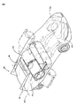
図1は、飛行モード(図1)及び路面走行モード(図2)で操作可能な乗り物20を模式的に例示した図である。乗り物20は一般的に、少なくとも1つの操縦可能な車輪24A及び少なくとも1つの駆動輪24Bを含む複数の車輪24を有する車体22、動力システム26、推進システム28、先尾翼30、尾翼32及び翼システム34を含む。特定のシステム及びサブシステムが個々に定義されているが、サブシステムのそれぞれ又そのうちのいずれかを組み合わせるか、又は分離し得るということが理解されるべきである。
FIG. 1 is a diagram schematically illustrating a
車体22には、運転者、乗客及び貨物のための座席が設けられている。車体22は、路面走行モード(図2)における操作のために、複数の車輪24上に支持される。先尾翼30、尾翼32及び翼システム34は、路面走行モードの際に、目立たずかつスタイリッシュであり、運転者の側方及び後方への視野も妨げない設計の可能性を促進するために、車体22内部に容易に収納可能である。1つの例においては、幅が約6フィート(約182.88cm)、離陸全備重量が3200ポンド(約1451.50kg)である車体22に対して、約18フィート(約548.64cm)の翼幅が提供される。開示される非限定的実施形態においては、特定の構成及び形状で描写されているが、本明細書に記載される概念は、例示されるこれらのものにのみ限定されるものではないことが理解されるべきである。
The
開示される非限定的実施形態における1対の先尾翼30は、操縦可能な車輪24Aそれぞれの前方に位置する。各先尾翼30は、乗り物20の縦操縦及び横操縦を容易にするために、それぞれの軸線Cを中心に傾斜する全可動面であってもよい。各先尾翼30は、車体22内部に少なくとも部分的に収納されるために(図2)、軸線CS(図3)を中心に回転可能である。この開示される非限定的実施形態において、各先尾翼30は、収納された路面走行モード及び展開された飛行モードの間で、軸線CSを中心に約135度の回転距離で回転可能である。例えばスライド式、伸縮式、又は他の配置などの他の収納配置もまた、本開示により利益を受けるということが理解されるべきである。
A pair of leading
尾翼32は一般的に、間に昇降舵40を挟んで、左舷及び右舷垂直安定板36、38を含む。開示される非限定的実施形態において、垂直安定板(vertical stabilizers)36、38は、それぞれ、方向操縦を容易にするための方向舵42、44を含む。昇降舵40は、乗り物20の縦操縦を容易にするために、軸線Eを中心に傾斜する全可動面であってもよい。
The
尾翼32は、路面走行モードにおける、車体22内部への収納のために、軸線ESを中心に回転可能である。尾翼32が車体22内に向かって回転すると、昇降舵40は、車体22内への、少なくとも部分的な収納を可能にするために、その軸線Eを中心に傾斜し得る。すなわち、昇降舵40は、車体22に対して、実質的に平らになるように傾斜し(pitched)得る。あるいは、昇降舵40は、乗り物20が路面走行モードにあるとき、スポイラーとして機能し得るように配置されてもよい。例えばスライド式配置などの他の収納配置もまた、本開示により利益を受けるということが理解されるべきである。
The
動力システム26は、路面走行モードにおいては駆動輪24Bに、及び飛行モードにおいては推進システム28に、選択的に動力を提供するように機能する。種々の前輪駆動、後輪駆動及び全輪駆動が、本開示により利益を受けるということが理解されるべきである。動力システム26は、内燃装置、ガスタービン装置、ハイブリッド電気装置、燃料電池装置、及び他のエネルギー変換装置を含む、種々の形態であり得るが、これらに限定されるものではない。
The
1つの開示される非限定的実施形態において、翼トルク箱構造(wing torque box structure)46は、車体22および翼システム34に対する支持を提供するために、乗員室48の後方に位置する。翼トルク箱構造46は、一般に乗り物20の重心位置(CG)に位置し、さらに燃料を備蓄するための燃料タンクとして機能し得る。1つの例において、210リットル(55ガロン)の燃料がその中に容易に備蓄される。CGに位置することにより、燃料量の変化は、乗り物20に対して最小の影響しか及ぼさず、例として約475マイル(約764.27km)、45分間の範囲の予備保持量を提供する。
In one disclosed non-limiting embodiment, a wing torque box structure 46 is located behind the passenger compartment 48 to provide support for the
開示される非限定的実施形態における翼システム34は、左舷翼50及び右舷翼52を含み、そのそれぞれがインボードチャネル54及びアウトボードチャネル56を有する二重チャネル翼である。インボードチャネル54は、インボード軸線IPの周りに画定され、アウトボードチャネル56は、アウトボード軸線OPの周りに画定される。左舷翼50及び右舷翼52は、アウトボードチャネル56が、インボードチャネル54から翼幅方向に延びるように、軸線WSを中心にして翼トルク箱構造46に取り付けられている。
The
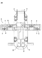
この開示される非限定的実施形態において、アウトボードチャネル56は、アウトボードチャネル56がインボードチャネル54の上に収納されるように、翼弦軸線Wを中心に約180度揺動する(図4)。すなわち、アウトボードチャネル56は、インボードチャネル54の上に収納され、実質的に、概ねコンパクトな円筒形状を形成する。各翼50、52もまた、車体22内部に収納される路面走行モード及び展開された飛行モードの間で、折りたためるように、翼軸線WSを中心に、180度揺動する。翼軸線WSは、翼弦軸線Wに対して垂直であってもよく、又は、アウトボードチャネル56がインボードチャネル54の上に収納されて実質上円筒形状を形成し、ついで該円筒が翼弦軸線Wを中心に揺動して車体22内部に収納されるように、小さなねじり変位を与えてもよい。例えばスライド式配置などの他の収納配置もまた、本開示により利益を受けるということが理解されるべきである。また、路面走行モードにける、目立たずかつスタイリッシュな設計の可能性、及び飛行モードにおける、空気力学的に滑らかな面を可能にするために、種々の扉(図示せず)が設けられていてもよいということが理解されるべきである。
In this disclosed non-limiting embodiment, the
各翼50、52のインボードチャネル54及びアウトボードチャネル56は、推進システム28の推進器60、62を支持するそれぞれの支柱58を含む。推進器60、62を支持するそれぞれの支柱58は、傾斜が固定されていてもよく、又は推力偏向を容易にするために、ティルトローター機能を提供し得るということが、理解されるべきである。各推進器60、62は、それぞれインボード軸線IP及びアウトボード軸線OPに沿って位置する、推進プロペラ、オープンローター、プロップローター、ターボファン又は他の推力発生システムを含み得る。1つの例においては、例えば電気モーターで駆動されるプロペラなどの、各推進器60、62は、約55hpの推力を発生させる。
The
アウトボードチャネル56がインボードチャネル54の上に収納される際に障害とならないように、各推進器60、62を軸方向にオフセットすることができる。この開示される非限定的実施形態において、アウトボード推進器62は、インボード推進器60の軸方向前方に位置する。
Each
各アウトボード推進器62の後方には、乗り物20の横操縦および縦操縦を容易にするために、補助翼64が、アウトボードチャネル56に渡って位置している。各補助翼64は、乗り物20の横操縦を容易にするために、軸線Aを中心に傾斜する全可動面であってもよい。アウトボード推進器62が、それぞれの補助翼64の前方にあるため、横操縦はアウトボード推進器62からの直接気流により増強され、ウェーク対応(wake enabled)の低速の横操縦および縦操縦を提供する。
Behind each
推進器スリップストリームを使用することにより、翼システム34は、高揚力形態幾何学を変化させることなく、有意な揚力係数及び効率的な下向きの推力偏向を提供する。このような高揚力形態は、小さな敷地や、ますます過密化する都市環境から運用される個人輸送、及び軍事輸送に付随する、数多くの利益を提供する、短距離離着陸(STOL)又は垂直・短距離離着陸(VSTOL)能力を促進する。
By using a propeller slipstream, the
図5を参照すると、別の開示される非限定的実施形態において、翼50、52のそれぞれは、揚力をさらに増大させる吹き出しチャネル循環制御翼(CCW)70である。種々の循環制御翼/上面吹き出し(CCW/USB)及び/又は境界層制御装置(BLCS)空気圧式システムもまた本開示により利益を受けるということが理解されるべきである。このような空気圧式チャネル翼システムによる揚力増強は、比較的小さい翼面積を可能にする(図6)。このような翼50、52の面積は、典型的な民間機の翼の面積の約30%であり得るが、それでもなお、後縁フラップを有するこのような従来の翼の約350%から500%、及びフラップの無い従来の翼と比較して最大900%の、揚力増強を提供する。
Referring to FIG. 5, in another disclosed non-limiting embodiment, each of the
吹き出しチャネルCCW70は、一般的に、関連する前縁スロット74に給気する(feeds)前縁給気プレナム72、及び関連する後縁スロット78に給気する後縁給気プレナム76を含む。給気プレナム72、76は空気源システム80に連結され、加圧された空気をスロット74、78から選択的に排気する。スロット74、78を介した加圧された空気の選択的な排気により、エアロカー、すなわち路面走行可能な航空機型の乗り物に一般に望まれるとおり、非常に低い飛行速度においても、乗り物20のSTOL、VSTOL、方向操縦、横操縦、及び縦操縦の操縦性増強を促進することができる。
The
図7を参照すると、1つの開示される非限定的実施形態において、動力システム26は、発電機92に動力を供給する内燃機関90を含む。内燃機関90は、高所での動作を促進するスーパーチャージャー又はターボチャージャーであってもよい。発電機92は、推進システム28の推進器60、62を駆動する配電構造(electric distributed architecture)に電力を提供する。例えば左舷及び右舷垂直安定板36、38内に位置する電池システム94は、電力の貯蔵を提供し、効率的な路面走行及び飛行操作、ならびにエンジン出力低下状態において操縦システムに動力を供給するための発電機92のフェイルセーフ動作を、さらに促進する。1つの例においては、約275hpの能力を有する内燃機関90は、発電機92に動力を供給して、クルーズ時に推進器60、62に連続的に動力を供給すると同時に、約23kWhの、例示される電池システム94を再充電する。
Referring to FIG. 7, in one disclosed non-limiting embodiment, the
内燃機関90は、シャフト96を介して駆動輪24Bに動力を供給することができ、かつ空気源システム80にも動力を供給し得る。空気源システム80は、乗員室48に空気調節を提供し、かつ吹き出しチャネルCCW70に高圧空気を提供するための、1つ又は複数のコンプレッサーを含んでいてもよい。
The internal combustion engine 90 can supply power to the drive wheels 24 </ b> B via the
図8を参照すると、別の開示される非限定的実施形態における動力システム26は、ガスタービンエンジン100及び発電機102を含む。ガスタービンエンジン100は抽気(bleed air)を提供し、それにより直接的に吹き出しチャネルCCW70に供給することができ、それによって内燃機関を有する実施形態と比較して、コンプレッサーの数を低減させ得る。空気源システム80は、乗員室48に空気調節を提供し、かつ、例えば、エンジン出力低下状態が発生して抽気が利用できなくなった場合には、吹き出しチャネルCCW70に高圧空気のフェイルセーフ供給を提供するための、1つ又は複数のコンプレッサーをさらに含んでいてもよい。
Referring to FIG. 8, a
全体として、翼システム34は、デュアルモード移行のための翼/車体統合を促進する翼面積の低減を生み出し、クルーズに必要とされる動力を低減させ、かつ、よりコンパクトな翼はより大型の翼に比べて突風に対してより低感度であるため、乗り心地を改善する。
Overall, the
例えば「前方(forward)」「後方(aft)」「上部の(upper)」「下部の(lower)」「の上(above)」「の下(below)」等の、相対的な位置を表す用語は、乗り物の通常の操作姿勢を基準にしたものであり、限定するものと考慮されるべきではないということが、理解されるべきである。 For example, “forward”, “after”, “upper”, “lower”, “above”, “below”, etc. It should be understood that the terminology is based on the normal operating posture of the vehicle and should not be considered limiting.
異なる非限定的実施形態が、特定の例示される要素を有するが、本発明の実施形態はこれらの特定の組み合わせに限定されない。非限定的実施形態のうちのいずれかからの構成要素又は特徴のうちのいくつかを、他の非限定的実施形態のうちのいずれかからの特徴又は構成要素と組み合わせて使用することが可能である。 Although different non-limiting embodiments have certain illustrated elements, embodiments of the invention are not limited to these specific combinations. Some of the components or features from any of the non-limiting embodiments can be used in combination with the features or components from any of the other non-limiting embodiments. is there.
複数の図面に渡って、同様の参照番号が、対応するか又は類似する要素を特定するということが理解されるべきである。また、特定の構成要素の配置が例示される実施形態において開示されているが、他の配置もまた、本開示により利益を受けるということが理解されるべきである。 It should be understood that like reference numerals identify corresponding or similar elements throughout the drawings. Also, although specific component arrangements are disclosed in the illustrated embodiments, it should be understood that other arrangements may also benefit from the present disclosure.
特定の工程の順番が示され、説明され、及び請求されているが、特に指示がない限り、各工程は、あらゆる順番で、個々に、又は組み合わせて実施してもよく、それでもなお本開示から利益を受けるということが、理解されるべきである。 Although a particular sequence of steps is shown, described, and claimed, unless otherwise indicated, each step may be performed in any order, individually or in combination and still from the present disclosure. It should be understood that it will benefit.
前述の記載は、制限するためのものではなく、例示的なものである。種々の非限定的実施形態が本明細書に開示されているが、当業者は、上述される教示に照らして、種々の改変及び変形が、添付される請求の範囲の範囲内に含まれるということを認識するであろう。したがって、添付される請求の範囲の範囲内で、具体的に記載される以外の様式で、本開示を実践し得るということが理解される。それゆえ、本発明の真の範囲及び内容を判断するためには、添付される請求の範囲が検討されるべきである。 The foregoing description is exemplary rather than limiting. While various non-limiting embodiments have been disclosed herein, those skilled in the art will recognize that various modifications and variations are within the scope of the appended claims in light of the above teachings. You will recognize that. Accordingly, it is understood that the present disclosure may be practiced other than as specifically described within the scope of the appended claims. Therefore, the appended claims should be studied to determine the true scope and content of this invention.
20 乗り物
28 推進システム
54 インボードチャネル
56 アウトボードチャネル
60 インボード推進器
62 アウトボード推進器
20
Claims (20)
インボード部と、
アウトボード部と、
当該翼の前記アウトボード部に配置された第1のチャネルと、
当該翼の前記インボード部に配置された第2のチャネルと、
前記第1のチャネルの軸線に沿って配置された第1の推進器と、
前記第2のチャネルの軸線に沿って配置された第2の推進器と、
制御面と、を具備する翼であって、
前記第1の推進器及び前記第2の推進器の一方が当該翼の後縁の近くに配置されると共に、前記第1の推進器及び前記第2の推進器の他方が当該翼の前縁に向かってそれぞれの前記軸線上で前方にオフセットされ、
前記制御面が前方にオフセットされた前記推進器の前記チャネル内に配置されると共に、前方にオフセットされた前記推進器から下流に配置された、翼。 Wings,
The inboard part,
The outboard section,
A first channel disposed in the outboard portion of the wing;
A second channel disposed in the inboard portion of the wing;
A first propeller disposed along an axis of the first channel;
A second propeller disposed along the axis of the second channel;
A wing having a control surface,
One of the first propulsion device and the second propulsion device is disposed near a trailing edge of the wing, and the other of the first propulsion device and the second propulsion device is a leading edge of the wing. Offset forward on each said axis towards
A wing, wherein the control surface is disposed in the channel of the thruster offset forward and is located downstream from the thruster offset forward.
前記制御面が補助翼である、請求項1に記載の翼。 The first thruster is the thruster offset forward, and the control surface is disposed in the first channel;
The wing according to claim 1, wherein the control surface is an auxiliary wing.
当該翼は、折りたたまれた構成において前記アウトボード部が前記インボード部の上で収納されるように、前記第1のチャネルと前記第2のチャネルとの間に配置された翼弦軸線周りに折りたたむように構成された、請求項1に記載の翼。 The inboard part and the outboard part are arranged adjacent to each other along the width of the wing;
The wing is about a chord axis disposed between the first channel and the second channel so that the outboard portion is housed on the inboard portion in a folded configuration. The wing according to claim 1, wherein the wing is configured to fold.
前記折りたたまれた構成のときに、前記第1の推進器、前記第2の推進器及び前記制御面が、全て前記筒内に配置される、請求項3に記載の翼。 When in the folded configuration, the first channel and the second channel form a cylinder;
The wing according to claim 3, wherein in the folded configuration, the first propulsion device, the second propulsion device, and the control surface are all disposed in the cylinder.
前縁給気プレナム及び少なくとも1つの前縁スロットを有し、
前記前縁給気プレナムが、前記少なくとも1つの前縁スロットに加圧された空気を供給するように構成され、
前記少なくとも1つの前縁スロットが、前記加圧された空気を当該翼の上面に吐出するように構成された、請求項6に記載の翼。 The blowout channel circulation control wing (CCW) system comprises:
A leading edge air supply plenum and at least one leading edge slot;
The leading edge air supply plenum is configured to supply pressurized air to the at least one leading edge slot;
The wing of claim 6, wherein the at least one leading edge slot is configured to discharge the pressurized air to an upper surface of the wing.
後縁給気プレナム及び少なくとも1つの後縁スロットを更に有し、
前記後縁給気プレナムが、前記少なくとも1つの後縁スロットに加圧された空気を供給するように構成され、
前記少なくとも1つの後縁スロットが、当該翼の前記後縁の下流に前記加圧された空気を吐出するように構成された、請求項7に記載の翼。 The blowout channel circulation control wing (CCW) system comprises:
A trailing edge air supply plenum and at least one trailing edge slot;
The trailing edge air supply plenum is configured to supply pressurized air to the at least one trailing edge slot;
The wing of claim 7, wherein the at least one trailing edge slot is configured to discharge the pressurized air downstream of the trailing edge of the wing.
後縁給気プレナム及び少なくとも1つの後縁スロットを更に有し、
前記後縁給気プレナムが、前記少なくとも1つの後縁スロットに加圧された空気を供給するように構成され、
前記少なくとも1つの後縁スロットが、当該翼の前記後縁の下流に前記加圧された空気を吐出するように構成された、請求項6に記載の翼。 The blowout channel circulation control wing (CCW) system comprises:
A trailing edge air supply plenum and at least one trailing edge slot;
The trailing edge air supply plenum is configured to supply pressurized air to the at least one trailing edge slot;
The wing of claim 6, wherein the at least one trailing edge slot is configured to discharge the pressurized air downstream of the trailing edge of the wing.
インボードチャネル区分と、
アウトボードチャネル区分と、
前記アウトボードチャネル区分の軸線に沿って配置された第1のプロペラと、
前記第1のプロペラのアウトボードチャネル内であって前記第1のプロペラの下流に配置された制御面と、
を具備し、
前記インボードチャネル区分及び前記アウトボードチャネル区分が、当該二重チャネル翼の翼幅に沿って隣接して配置され、
当該二重チャネル翼は、前記アウトボードチャネル区分が前記インボードチャネル区分の上で収納されるように前記インボードチャネル区分と前記アウトボードチャネル区分との間に配置された翼弦軸線周りに折りたたむように構成された、二重チャネル翼。 A double channel wing,
Inboard channel classification ,
Outboard channel classification ,
A first propeller disposed along an axis of the outboard channel section;
A control surface disposed in an outboard channel of the first propeller and downstream of the first propeller;
Comprising
The inboard channel section and the outboard channel section are disposed adjacently along the span of the dual channel wing;
The dual channel wing folds around a chord axis disposed between the inboard channel section and the outboard channel section such that the outboard channel section is received over the inboard channel section. Constructed as a double channel wing.
前記制御面は、補助翼を更に有し、
前記第1のプロペラ及び前記第2のプロペラの一方が当該二重チャネル翼の後縁側に配置されると共に、前記第1のプロペラ及び前記第2のプロペラの他方がそれぞれの軸線上で当該二重チャネル翼の前縁側へと前方にオフセットされ、
前記補助翼が、前方にオフセットされた前記プロペラのチャネル内に配置されると共に前方にオフセットされた前記プロペラの下流に配置された、請求項12に記載の二重チャネル翼。 Further comprising a second propeller disposed along an axis of the inboard channel section;
The control surface further includes an auxiliary wing,
One of the first propeller and the second propeller is disposed on a trailing edge side of the double channel blade, and the other of the first propeller and the second propeller is on the respective axis. Offset forward to the leading edge of the channel wing,
The dual channel wing of claim 12, wherein the auxiliary wing is disposed in a channel of the propeller offset forward and downstream of the propeller offset forward.
機体と、
少なくとも1つの請求項13に記載の二重チャネル翼と、を具備し、
少なくとも1つの前記二重チャネル翼が、前記機体に接続された、エアロカー。 An aero car,
The aircraft,
At least one dual channel wing according to claim 13,
An aerocar, wherein at least one of the dual channel wings is connected to the airframe.
該吹き出しチャネル循環制御翼(CCW)システムが、
前縁給気プレナム、及び、
少なくとも1つの前縁スロットを有し、
前記前縁給気プレナムが、前記少なくとも1つの前縁スロットに加圧された空気を供給するように構成され、
前記少なくとも1つの前縁スロットが、少なくとも1つの当該二重チャネル翼の上面上に前記加圧された空気を吐出するように構成された、請求項12に記載の二重チャネル翼。 Further comprising a blowout channel circulation control wing (CCW) system;
The blowout channel circulation control wing (CCW) system comprises:
Leading edge air supply plenum, and
Having at least one leading edge slot;
The leading edge air supply plenum is configured to supply pressurized air to the at least one leading edge slot;
The dual channel airfoil of claim 12, wherein the at least one leading edge slot is configured to discharge the pressurized air onto an upper surface of the at least one such dual channel airfoil.
後縁給気プレナム、及び、
少なくとも1つの後縁スロットを更に具備し、
前記後縁給気プレナムが、前記少なくとも1つの後縁スロットに加圧された空気を供給するように構成され、
前記少なくとも1つの後縁スロットが、少なくとも1つの当該二重チャネル翼の後縁の下流に前記加圧された空気を吐出するように構成された、請求項16に記載の二重チャネル翼。 The blowout channel circulation control wing (CCW) system comprises:
Trailing edge air supply plenum, and
Further comprising at least one trailing edge slot;
The trailing edge air supply plenum is configured to supply pressurized air to the at least one trailing edge slot;
The dual channel airfoil of claim 16, wherein the at least one trailing edge slot is configured to discharge the pressurized air downstream of a trailing edge of at least one of the dual channel airfoils.
該吹き出しチャネル循環制御翼(CCW)システムが、
後縁給気プレナム、及び、
少なくとも1つの後縁スロットを更に有し、
前記後縁給気プレナムが、前記少なくとも1つの後縁スロットに加圧された空気を供給するように構成され、
前記少なくとも1つの後縁スロットが、少なくとも1つの当該二重チャネル翼の後縁の下流に前記加圧された空気を吐出するように構成された、請求項12に記載の二重チャネル翼。 Further comprising a blowout channel circulation control wing (CCW) system;
The blowout channel circulation control wing (CCW) system comprises:
Trailing edge air supply plenum, and
Further comprising at least one trailing edge slot;
The trailing edge air supply plenum is configured to supply pressurized air to the at least one trailing edge slot;
The double channel airfoil of claim 12, wherein the at least one trailing edge slot is configured to discharge the pressurized air downstream of a trailing edge of at least one of the dual channel airfoils.
機体、及び、
少なくとも1つの二重チャネル翼、
を有する航空機を設けることであって、
前記少なくとも1つの二重チャネル翼が、
インボードチャネル区分と、
アウトボードチャネル区分と、
前記アウトボードチャネル区分の軸線に沿って配置された第1のプロペラと、
前記第1のプロペラのアウトボードチャネル内であって前記第1のプロペラの下流に配置された制御面とを有し、
前記インボードチャネル区分及び前記アウトボードチャネル区分が前記少なくとも1つの二重チャネル翼の翼幅に沿って隣接して配置され、
前記少なくとも1つの二重チャネル翼は、前記アウトボードチャネル区分が前記インボードチャネル区分の上で収納されるように、翼弦軸線周りに折りたたむように構成される、
航空機を設けることと、
前記アウトボードチャネル区分及び前記インボードチャネル区分を収納された状態へと配置するため前記アウトボードチャネル区分が前記インボードチャネル区分の上で収納されるように、前記アウトボードチャネル区分を前記翼弦軸線周りに揺動させることと、
前記アウトボードチャネル区分及び前記インボードチャネル区分を展開された状態へと配置するため前記アウトボードチャネル区分及び前記インボードチャネル区分が展開され且つ隣接して配置されるように、前記収納された状態から前記アウトボードチャネル区分を前記翼弦軸線周りに揺動させることと、を含む方法。 A method of storing and deploying at least one double channel wing of an aero car, the method comprising:
Aircraft and
At least one double channel wing,
Providing an aircraft having
The at least one double channel wing
Inboard channel classification ,
Outboard channel classification ,
A first propeller disposed along an axis of the outboard channel section;
A control surface disposed in an outboard channel of the first propeller and downstream of the first propeller ;
The inboard channel section and the outboard channel section are disposed adjacently along a span of the at least one dual channel wing;
The at least one dual channel wing is configured to fold around a chord axis such that the outboard channel section is received over the inboard channel section.
Providing an aircraft,
The outboard channel section is placed on the chord such that the outboard channel section is housed on the inboard channel section to place the outboard channel section and the inboard channel section into the housed state. Swing around the axis,
The stowed state such that the outboard channel section and the inboard channel section are deployed and arranged adjacent to each other to place the outboard channel section and the inboard channel section in the deployed state. Swinging the outboard channel section about the chord axis.
前記少なくとも1つの二重チャネル翼を収納された状態へと配置するため前記少なくとも1つの二重チャネル翼が前記機体の略幅寸法内に配置されるように、折りたたまれた前記インボードチャネル区分及びアウトボードチャネル区分を前記略鉛直な軸線周りに一体として枢動させることと、
前記インボードチャネル区分及び前記アウトボードチャネル区分を展開された状態へと展開する前に、収納された前記少なくとも1つの二重チャネル翼を前記機体の前記略幅寸法内から前記略鉛直な軸線周りに枢動させることと、を更に含む、請求項19に記載の二重チャネル翼を収納及び展開する方法。 The inboard channel section and the outboard channel section are configured to pivot together about a substantially vertical axis near the root of the at least one dual channel wing when folded, the method comprising:
The inboard channel section folded so that the at least one double channel wing is positioned within a substantially width dimension of the fuselage to place the at least one double channel wing into a retracted state; and Pivoting the outboard channel section together about the substantially vertical axis;
Before deploying the inboard channel section and the outboard channel section to a deployed state, the stored at least one double channel wing is moved from within the substantial width dimension of the fuselage around the generally vertical axis. The method of retracting and deploying a dual channel wing according to claim 19, further comprising:
Applications Claiming Priority (2)
| Application Number | Priority Date | Filing Date | Title |
|---|---|---|---|
| US14/180,614 US9156550B2 (en) | 2014-02-14 | 2014-02-14 | Dual channel wing for an aerocar |
| US14/180,614 | 2014-02-14 |
Publications (3)
| Publication Number | Publication Date |
|---|---|
| JP2015151128A JP2015151128A (en) | 2015-08-24 |
| JP2015151128A5 JP2015151128A5 (en) | 2016-02-25 |
| JP6039714B2 true JP6039714B2 (en) | 2016-12-07 |
Family
ID=53797425
Family Applications (1)
| Application Number | Title | Priority Date | Filing Date |
|---|---|---|---|
| JP2015026445A Active JP6039714B2 (en) | 2014-02-14 | 2015-02-13 | Wing, aero car and method for storing and deploying the wing |
Country Status (2)
| Country | Link |
|---|---|
| US (1) | US9156550B2 (en) |
| JP (1) | JP6039714B2 (en) |
Cited By (1)
| Publication number | Priority date | Publication date | Assignee | Title |
|---|---|---|---|---|
| KR102164227B1 (en) * | 2019-06-17 | 2020-10-12 | 한국기계연구원 | A lift force generating apparatus and flying vehicles having the same |
Families Citing this family (28)
| Publication number | Priority date | Publication date | Assignee | Title |
|---|---|---|---|---|
| USD951137S1 (en) * | 2002-10-01 | 2022-05-10 | Dylan T X Zhou | Hybrid vertical takeoff and landing flying automobile |
| CN103692873B (en) * | 2013-12-20 | 2015-11-18 | 胡新如 | A kind of land and water hovercar |
| US10081424B2 (en) * | 2013-12-31 | 2018-09-25 | Bogdan Radu | Flying car or drone |
| EP2995553B1 (en) * | 2014-09-09 | 2017-02-01 | Airbus Defence and Space GmbH | Air generation unit for an aircraft and method for its operation |
| US11718403B2 (en) * | 2015-04-15 | 2023-08-08 | Northrop Grumman Systems Corporation | Extremely quiet short take-off and landing (STOL) aircraft |
| US20160368339A1 (en) | 2015-06-19 | 2016-12-22 | Toyota Motor Engineering & Manufacturing North America, Inc. | Aerodynamic lift enhancing system for a flying automotive vehicle |
| US11027584B1 (en) * | 2015-07-22 | 2021-06-08 | Taras Kiceniuk, Jr. | Flying car with fore and aft lifting surfaces |
| US10696390B2 (en) * | 2016-09-08 | 2020-06-30 | Hop Flyt Inc | Aircraft having independently variable incidence channel wings with independently variable incidence channel canards |
| FR3057851A1 (en) * | 2016-10-26 | 2018-04-27 | Airbus Safran Launchers Sas | ACTIVE-PORTABLE PROPULSIVE DEVICE WITH IMPROVED MANEUVERABILITY |
| US10730607B2 (en) * | 2016-11-15 | 2020-08-04 | Colorado Seminary Which Owns And Operates The University Of Denver | Circulation control system for aerial vehicles |
| US10800521B1 (en) * | 2016-11-28 | 2020-10-13 | Amazon Technologies, Inc. | Configurable aerial vehicles |
| CN107264776A (en) * | 2017-06-16 | 2017-10-20 | 青岛华创风能有限公司 | A kind of fluid exciting bank for wings/blades |
| CN107344611A (en) * | 2017-06-16 | 2017-11-14 | 青岛华创风能有限公司 | Wings/blades gas energizer |
| JP6425323B1 (en) * | 2017-07-27 | 2018-11-21 | 株式会社辰巳菱機 | Floating type moving device |
| EP3659915A4 (en) * | 2017-07-27 | 2021-04-28 | Tatsumi Ryoki Co., Ltd | Hovering vehicle |
| CN107745797B (en) * | 2017-09-12 | 2019-06-04 | 廖超辉 | A kind of slit wing, a kind of compound wing and its a kind of slit machine leaf |
| US10946705B1 (en) | 2017-10-31 | 2021-03-16 | Toyota Motor Engineering & Manufacturing North America, Inc. | Flight module for an aerial vehicle |
| WO2019148464A1 (en) * | 2018-02-02 | 2019-08-08 | 浙江吉利控股集团有限公司 | Flying car wing, carrier module structure, power system, flying car, and control method for flying car wing |
| CN109592034B (en) * | 2019-01-31 | 2023-12-19 | 上海交通大学 | Submersible aircraft and wing storage method thereof |
| CN113840742A (en) * | 2019-05-07 | 2021-12-24 | 恩福特公司 | Traveling and flying electric and hybrid VTOL vehicle |
| US11820509B2 (en) * | 2019-09-20 | 2023-11-21 | Hop Flyt, Inc. | Retractable duct channel wing |
| DE102019131673A1 (en) * | 2019-11-22 | 2021-05-27 | Timo Schnoelzer | Means of transport for a flight operation and methods for transporting a load |
| US11738865B1 (en) * | 2021-02-01 | 2023-08-29 | Hyalta Aeronautics, Inc. | Convertible unmanned vehicle |
| CN113009336B (en) * | 2021-02-25 | 2024-02-09 | 长春汽车工业高等专科学校 | New energy automobile motor power detection device with elasticity buffer gear |
| CN113415115A (en) * | 2021-07-22 | 2021-09-21 | 田丰年 | Aerocar wing and rotor hybrid retraction system and aerocar |
| CN113998123B (en) * | 2021-10-09 | 2023-06-02 | 广东汇天航空航天科技有限公司 | Power system, flyable device and power control method |
| WO2023177774A1 (en) * | 2022-03-17 | 2023-09-21 | Nft Inc. | Hybrid road-air vehicle |
| DE102022109583A1 (en) * | 2022-04-20 | 2023-10-26 | Timo Schnoelzer | Means of transport for transporting a load in a driving operation and in a flight operation and method |
Family Cites Families (63)
| Publication number | Priority date | Publication date | Assignee | Title |
|---|---|---|---|---|
| US3123321A (en) * | 1964-03-03 | Aircraft channel wing propeller combination | ||
| US1793349A (en) * | 1929-03-06 | 1931-02-17 | Andersson Ivan | Airplane |
| US2011254A (en) * | 1933-07-07 | 1935-08-13 | Robert J Nightingale | Aeroplane |
| US1998148A (en) * | 1934-04-18 | 1935-04-16 | Vieriu Daniel | Auto-aeroplane |
| US2021324A (en) * | 1934-06-29 | 1935-11-19 | Curtiss Aeroplane & Motor Co | Folding wing airplane |
| US2166564A (en) * | 1936-03-04 | 1939-07-18 | Douglas Aircraft Co Inc | Airplane having folding wings |
| US2343645A (en) * | 1940-07-03 | 1944-03-07 | Curtiss Wright Corp | Folding wing airplane |
| US2437684A (en) | 1940-08-31 | 1948-03-16 | Willard R Custer | Aircraft having high-lift wing channels |
| US2290850A (en) * | 1940-10-09 | 1942-07-21 | Brewster Aeronautical Corp | Folding wing airplane |
| US2510959A (en) * | 1942-04-16 | 1950-06-13 | Willard R Custer | Airplane with high-lift channeled wings |
| US2428737A (en) * | 1942-08-28 | 1947-10-07 | Louis H Crook | Boundary layer remover for airplanes |
| US2374493A (en) * | 1942-10-12 | 1945-04-24 | Lindley W Moore | Airplane |
| US2424556A (en) * | 1944-06-17 | 1947-07-29 | Willard R Custer | Multiple propeller wing channel |
| US2476482A (en) * | 1945-09-20 | 1949-07-19 | Willard R Custer | Channeled airplane wing and propulsion means therefor |
| US2532481A (en) * | 1946-10-09 | 1950-12-05 | Willard R Custer | Multiple channel wing airplane |
| US2532482A (en) * | 1947-08-06 | 1950-12-05 | Willard R Custer | Boundary layer remover for airplanes |
| US2514478A (en) * | 1947-08-14 | 1950-07-11 | Willard R Custer | Channel wing airplane |
| US2611556A (en) * | 1947-09-19 | 1952-09-23 | Willard R Custer | Jet-propelled aircraft with lift channels |
| US2687262A (en) * | 1947-09-19 | 1954-08-24 | Willard R Custer | Jet propelled channeled aircraft |
| US2674422A (en) * | 1949-05-12 | 1954-04-06 | Pellarini Luigi | Folding wing for roadable aircraft |
| US2589994A (en) * | 1950-01-03 | 1952-03-18 | Willard R Custer | High lift wing channel with movable wing |
| US2611555A (en) * | 1950-01-31 | 1952-09-23 | Willard R Custer | Jet-propelled aircraft with fuselage lifting channels |
| US2665083A (en) * | 1950-01-31 | 1954-01-05 | Willard R Custer | Jet-propelled channel aircraft |
| US2693920A (en) * | 1951-12-17 | 1954-11-09 | Taylor Clarence Gilbert | Adjustable lift-propulsion device for aircraft |
| US2691494A (en) * | 1952-06-10 | 1954-10-12 | Willard R Custer | Airplane with pressure balanced wing channels |
| US2712421A (en) * | 1953-08-21 | 1955-07-05 | North American Aviation Inc | Folding wing aircraft |
| US2937823A (en) * | 1954-06-03 | 1960-05-24 | Fletch Aire Company Inc | Vertical rising convertiplane having tilting wing channel boundary layer control system |
| US2961188A (en) | 1956-05-02 | 1960-11-22 | Josephine M Taylor | Lift-propulsion device for aircraft |
| US2940688A (en) * | 1956-08-27 | 1960-06-14 | Edward F Bland | Roadable aircraft and sailboat |
| US2957647A (en) | 1958-02-24 | 1960-10-25 | Glenn B Shew | High-lift aircraft |
| US3045947A (en) * | 1959-04-24 | 1962-07-24 | Bertin & Cie | Ejectors, particularly for producing lift in aircraft |
| US3081965A (en) * | 1961-02-13 | 1963-03-19 | Glenn B Shew | Channel winged aircraft |
| US3504873A (en) | 1966-09-02 | 1970-04-07 | Spence William | Curved wing structure for aircraft |
| US3647163A (en) * | 1969-11-19 | 1972-03-07 | Thomas E Sweeney | Foldable semirigid airfoil for airborne vehicles |
| US3650497A (en) * | 1969-11-26 | 1972-03-21 | Custer Channel Wing Corp | Jet propelled channeled aircraft |
| US3704842A (en) * | 1970-10-16 | 1972-12-05 | Willard R Custer | Contoured stack of jet engine with channel wing aircraft |
| US3705700A (en) * | 1970-10-23 | 1972-12-12 | Willard R Custer | Air flow control means for channel winged aircraft |
| US3806065A (en) * | 1971-03-11 | 1974-04-23 | W Custer | Adjustable geometry airfoil in channel winged aircraft |
| US3830450A (en) * | 1972-12-15 | 1974-08-20 | Us Navy | Dual purpose circulation control airfoil |
| US3868073A (en) * | 1974-01-30 | 1975-02-25 | Myron L King | Propulsion system for aircraft |
| US4463920A (en) * | 1981-02-25 | 1984-08-07 | The United States Of America As Represented By The Secretary Of The Navy | Thrust deflector and force augmentor |
| US4627585A (en) * | 1984-06-25 | 1986-12-09 | Harry Einstein | Pusher type auto-plane |
| FR2591559A2 (en) | 1985-02-13 | 1987-06-19 | Bazin Claudine | Aircraft convertible into a land vehicle |
| US4726546A (en) | 1986-11-17 | 1988-02-23 | Angelis Lawrence J De | Semi-venturi airfoil aircraft |
| US4804155A (en) * | 1987-03-02 | 1989-02-14 | Strumbos William P | VTOL aircraft |
| US5356094A (en) * | 1987-03-04 | 1994-10-18 | Rick Sylvain | Scorpion wing |
| JP3180115B2 (en) * | 1989-02-27 | 2001-06-25 | 良雄 野崎 | STOL aircraft |
| US5082204A (en) * | 1990-06-29 | 1992-01-21 | Croston Leon J | All wing aircraft |
| US5597137A (en) * | 1994-12-28 | 1997-01-28 | Skoglun; Willard | Vertical take-off and landing aircraft |
| US6086014A (en) * | 1998-08-12 | 2000-07-11 | Bragg, Jr.; Albert J. | Roadable aircraft |
| US6474604B1 (en) | 1999-04-12 | 2002-11-05 | Jerry E. Carlow | Mobius-like joining structure for fluid dynamic foils |
| US20030094536A1 (en) * | 2001-10-25 | 2003-05-22 | Labiche Mitchell G. | Flyable automobile |
| US6808140B2 (en) * | 2002-02-08 | 2004-10-26 | Moller Paul S | Vertical take-off and landing vehicles |
| US6619584B1 (en) * | 2002-03-11 | 2003-09-16 | Robin Haynes | Road/air vehicle |
| US7104498B2 (en) * | 2003-06-13 | 2006-09-12 | Georgia Tech Research Corp. | Channel-wing system for thrust deflection and force/moment generation |
| US7568657B2 (en) * | 2005-03-14 | 2009-08-04 | Milde Jr Karl F | VTOL personal aircraft |
| WO2007114877A2 (en) * | 2006-01-06 | 2007-10-11 | Terrafugia, Inc. | Roadable aircraft with folding wings and integrated bumpers and lighting |
| IL187368A (en) * | 2007-11-14 | 2016-04-21 | Vestal Ltd | Scoop-effect wing |
| US8162253B2 (en) * | 2009-08-19 | 2012-04-24 | Seiford Sr Donald S | Convertible vehicle for road, air, and water usage |
| US8282036B2 (en) * | 2009-12-15 | 2012-10-09 | Funck Stephen H | Multi wing aircraft |
| US20130193263A1 (en) * | 2010-07-23 | 2013-08-01 | Samuel Adam Schweighart | Roadable aircraft and related systems |
| US8573541B2 (en) * | 2010-09-13 | 2013-11-05 | John Sullivan | Wavy airfoil |
| US9139299B2 (en) * | 2012-07-10 | 2015-09-22 | Lapcad Engineering, Inc. | Vertical takeoff and landing roadable vehicle |
-
2014
- 2014-02-14 US US14/180,614 patent/US9156550B2/en not_active Expired - Fee Related
-
2015
- 2015-02-13 JP JP2015026445A patent/JP6039714B2/en active Active
Cited By (1)
| Publication number | Priority date | Publication date | Assignee | Title |
|---|---|---|---|---|
| KR102164227B1 (en) * | 2019-06-17 | 2020-10-12 | 한국기계연구원 | A lift force generating apparatus and flying vehicles having the same |
Also Published As
| Publication number | Publication date |
|---|---|
| US9156550B2 (en) | 2015-10-13 |
| US20150232180A1 (en) | 2015-08-20 |
| JP2015151128A (en) | 2015-08-24 |
Similar Documents
| Publication | Publication Date | Title |
|---|---|---|
| JP6039714B2 (en) | Wing, aero car and method for storing and deploying the wing | |
| CN111216883B (en) | Vertical take-off and landing multi-rotor aircraft with at least eight thrust producing units | |
| US20210206487A1 (en) | Aircraft and Modular Propulsion Unit | |
| CN106573678B (en) | Aircraft suitable for vertical take-off and horizontal flight | |
| US8511603B2 (en) | Roadable aircraft with collapsible wings and ductless fan | |
| US6896221B1 (en) | Vertical takeoff and landing aircraft | |
| US20180354613A1 (en) | Aerial vehicle | |
| US11858304B2 (en) | Multi-modal vehicle | |
| CN104918853A (en) | Convertible aircraft provided with two ducted rotors at the wing tips and with a horizontal fan in the fuselage | |
| WO2013159672A1 (en) | Flying automobile | |
| CN106379120A (en) | Transformation method of hybrid transportation vehicle for ground and air, and the hybrid transportation vehicle itself | |
| US4537373A (en) | Air vehicle having driven wheels and ducted fans | |
| US11027584B1 (en) | Flying car with fore and aft lifting surfaces | |
| CN206344647U (en) | New distribution type electric ducted fan wing flap high-lift system and its hovercar | |
| US20200079503A1 (en) | Folding Multi-rotor Vertical Takeoff and Landing Aircraft | |
| JP2022532546A (en) | An electric or hybrid VTOL vehicle that can travel and fly | |
| CN103921931A (en) | Duct wing system and aircraft using same | |
| CN105730168B (en) | Three culvert vertical take-off and landing hovercars | |
| US20200130825A1 (en) | Neutral axis duct with tandem telescopic thrust vectoring leading and trailing edge propellers for multi-mode spatial vehicle | |
| WO2012148035A1 (en) | Flying automobile | |
| CN110282117A (en) | A kind of city VTOL aircraft having wing-folding storage function | |
| EP3746364A1 (en) | Vtol aircraft | |
| JP2004082999A (en) | Vtol (vertical take-off and landing aircraft) | |
| CN112622548A (en) | Flying automobile | |
| CN114945509A (en) | Electrically propelled aircraft comprising a central wing and two rotatable lateral wings |
Legal Events
| Date | Code | Title | Description |
|---|---|---|---|
| A521 | Request for written amendment filed |
Free format text: JAPANESE INTERMEDIATE CODE: A523 Effective date: 20160105 |
|
| A621 | Written request for application examination |
Free format text: JAPANESE INTERMEDIATE CODE: A621 Effective date: 20160105 |
|
| A871 | Explanation of circumstances concerning accelerated examination |
Free format text: JAPANESE INTERMEDIATE CODE: A871 Effective date: 20160105 |
|
| A975 | Report on accelerated examination |
Free format text: JAPANESE INTERMEDIATE CODE: A971005 Effective date: 20160218 |
|
| A131 | Notification of reasons for refusal |
Free format text: JAPANESE INTERMEDIATE CODE: A131 Effective date: 20160412 |
|
| A521 | Request for written amendment filed |
Free format text: JAPANESE INTERMEDIATE CODE: A523 Effective date: 20160711 |
|
| TRDD | Decision of grant or rejection written | ||
| A01 | Written decision to grant a patent or to grant a registration (utility model) |
Free format text: JAPANESE INTERMEDIATE CODE: A01 Effective date: 20161004 |
|
| A61 | First payment of annual fees (during grant procedure) |
Free format text: JAPANESE INTERMEDIATE CODE: A61 Effective date: 20161104 |
|
| R150 | Certificate of patent or registration of utility model |
Ref document number: 6039714 Country of ref document: JP Free format text: JAPANESE INTERMEDIATE CODE: R150 |
|
| S111 | Request for change of ownership or part of ownership |
Free format text: JAPANESE INTERMEDIATE CODE: R313113 |
|
| R350 | Written notification of registration of transfer |
Free format text: JAPANESE INTERMEDIATE CODE: R350 |