JP6036621B2 - System, information processing device - Google Patents

System, information processing device Download PDF

Info

Publication number
JP6036621B2
JP6036621B2 JP2013192240A JP2013192240A JP6036621B2 JP 6036621 B2 JP6036621 B2 JP 6036621B2 JP 2013192240 A JP2013192240 A JP 2013192240A JP 2013192240 A JP2013192240 A JP 2013192240A JP 6036621 B2 JP6036621 B2 JP 6036621B2
Authority
JP
Japan
Prior art keywords
unit
image
display
remote
electronic blackboard
Prior art date
Legal status (The legal status is an assumption and is not a legal conclusion. Google has not performed a legal analysis and makes no representation as to the accuracy of the status listed.)
Active
Application number
JP2013192240A
Other languages
Japanese (ja)
Other versions
JP2015060305A (en
JP2015060305A5 (en
Inventor
剣持 栄治
栄治 剣持
崇範 永原
崇範 永原
笠谷 潔
潔 笠谷
Current Assignee (The listed assignees may be inaccurate. Google has not performed a legal analysis and makes no representation or warranty as to the accuracy of the list.)
Ricoh Co Ltd
Original Assignee
Ricoh Co Ltd
Priority date (The priority date is an assumption and is not a legal conclusion. Google has not performed a legal analysis and makes no representation as to the accuracy of the date listed.)
Filing date
Publication date
Application filed by Ricoh Co Ltd filed Critical Ricoh Co Ltd
Priority to JP2013192240A priority Critical patent/JP6036621B2/en
Publication of JP2015060305A publication Critical patent/JP2015060305A/en
Publication of JP2015060305A5 publication Critical patent/JP2015060305A5/ja
Application granted granted Critical
Publication of JP6036621B2 publication Critical patent/JP6036621B2/en
Active legal-status Critical Current
Anticipated expiration legal-status Critical

Links

Images

Landscapes

  • Controls And Circuits For Display Device (AREA)

Description

本発明は、表示手段に表示された画像を共有する複数の情報処理装置がネットワークを介して接続されたシステム等に関する。   The present invention relates to a system in which a plurality of information processing apparatuses that share an image displayed on a display unit are connected via a network.

企業や教育機関、行政機関等における会議等において、大型ディスプレイに背景画像を表示させ、この背景画像の上にユーザが文字や数字、図形等のストローク画像を描画可能な電子黒板が利用されている。このような電子黒板では、大型ディスプレイなどに対しユーザによって生成されたストローク画像を表示することができる。また、ユーザはストローク画像を表示できるだけでなく、表示している画像を編集したり、画像を保存することができる。   An electronic blackboard is used in which a background image is displayed on a large display at a meeting in a company, an educational institution, an administrative organization, etc., and a user can draw stroke images such as letters, numbers, and figures on the background image. . In such an electronic blackboard, a stroke image generated by the user can be displayed on a large display or the like. In addition to displaying the stroke image, the user can edit the displayed image and save the image.

また、ネットワークの普及に伴い各拠点の電子黒板をネットワークで接続して、ストローク画像などを各電子黒板が共有する技術も知られるようになった(例えば、特許文献1参照。)。特許文献1には、拠点識別情報を入力されたデータと共に送信し、操作者などの拠点情報を添付してデータを表示する相互情報共有システムが開示されている。   In addition, with the spread of networks, a technology is also known in which electronic blackboards at each base are connected by a network so that each electronic blackboard shares a stroke image or the like (see, for example, Patent Document 1). Patent Document 1 discloses a mutual information sharing system that transmits base identification information together with input data, and displays the data by attaching base information such as an operator.

しかしながら、このような電子黒板を用いたシステムでは、セキュリティ上の不都合が発生するおそれがあるという問題があった。すなわち、他の拠点の電子黒板と共有されたストローク画像が仮に機密情報を含んでいても、会議のすべての参加者が自由にストローク画像を編集したり保存することが可能になっている。このため、ストローク画像のオーナーが関知していない状態で、参加者がストローク画像を外部に送信したり、メモリーカードに記録して持ち出すことが可能となっていた。   However, in such a system using an electronic blackboard, there is a problem that a security inconvenience may occur. That is, even if the stroke image shared with the electronic blackboard at another base contains confidential information, all participants in the conference can freely edit and save the stroke image. For this reason, the participant can transmit the stroke image to the outside or record it on a memory card and take it out without the owner of the stroke image being aware.

本発明は、上記課題に鑑み、各拠点が共有する画像に対する操作を制限できるシステム等を提供することを目的とする。   In view of the above problems, an object of the present invention is to provide a system or the like that can restrict operations on images shared by each base.

上記課題を解決するため、本発明は、ネットワークを介して接続された複数の情報処理装置が通信するシステムであって、情報処理装置は、他の情報処理装置が操作を受け付けることを制限する操作制限の設定を受け付ける制限受け付け手段と、前記他の情報処理装置に前記操作制限の設定に基づく情報を送信する送信手段と、を有し、前記制限受け付け手段は、前記他の情報処理装置に接続された表示手段に表示された画像を保存する保存操作、前記表示手段に表示された画像を編集する編集操作、又は、前記他の情報処理装置に画像を表示する表示操作、の制限を受け付けることで、前記保存操作に分類される複数の操作、前記編集操作に分類される複数の操作、又は、前記表示操作に分類される複数の操作、の制限をまとめて受け付けるものであり、
前記他の情報処理装置は、前記操作制限の設定に基づく情報によって、前記他の情報処理装置の操作受け付け手段による操作の受け付けを制限させる、ことを特徴とする。
In order to solve the above problems, the present invention is a system in which a plurality of information processing devices connected via a network communicate with each other, and the information processing device is an operation that restricts other information processing devices from receiving operations A limit accepting unit that accepts a restriction setting; and a transmission unit that transmits information based on the operation restriction setting to the other information processing apparatus, and the limit accepting unit is connected to the other information processing apparatus. Receiving a restriction on a storage operation for saving the image displayed on the displayed display means, an editing operation for editing the image displayed on the display means, or a display operation for displaying the image on the other information processing apparatus. Thus, the restriction of a plurality of operations classified as the save operation, a plurality of operations classified as the editing operation, or a plurality of operations classified as the display operation is collectively accepted. It is those,
The other information processing apparatus is configured to restrict the acceptance of an operation by an operation accepting unit of the other information processing apparatus based on information based on the operation restriction setting.

各拠点が共有する画像に対する操作を制限できるシステム等を提供することができる。   It is possible to provide a system or the like that can restrict operations on images shared by each base.

画像処理システムの全体構成図の一例である。1 is an example of an overall configuration diagram of an image processing system. 電子黒板のハードウェア構成図の一例である。It is an example of the hardware block diagram of an electronic blackboard. 電子黒板の機能ブロック図の一例である。It is an example of the functional block diagram of an electronic blackboard. ファイル処理部の機能ブロック図の一例である。It is an example of a functional block diagram of a file processing unit. 通信制御部の機能ブロック図の一例である。It is an example of the functional block diagram of a communication control part. ページデータを模式的に説明する図の一例である。It is an example of the figure which illustrates page data typically. ストローク配列データを模式的に説明する図の一例である。It is an example of the figure which illustrates stroke sequence data typically. 座標配列データを模式的に説明する図の一例である。It is an example of the figure which illustrates coordinate arrangement data typically. メディアデータを模式的に説明する図の一例である。It is an example of the figure which illustrates media data typically. 遠隔ライセンス管理テーブルを模式的に説明する図の一例である。It is an example of the figure which illustrates a remote license management table typically. アドレス帳管理テーブルを模式的に説明する図の一例である。It is an example of the figure which illustrates an address book management table typically. バックアップデータを模式的に説明する図の一例である。It is an example of the figure which illustrates backup data typically. 接続先管理テーブルを模式的に説明する図の一例である。It is an example of the figure which illustrates a connecting point management table typically. 参加拠点管理テーブルを模式的に説明する図の一例である。It is an example of the figure which illustrates a participating base management table typically. 操作データを模式的に説明する図の一例である。It is an example of the figure which illustrates operation data typically. 機能制限管理部に記憶されている機能制限リストを模式的に説明する図の一例である。It is an example of the figure which illustrates typically the function restriction list memorized by the function restriction management part. 機能制限リストの作成画面の一例を示す図である。It is a figure which shows an example of the creation screen of a function restriction list. 機能制限リストの作成画面の一例を示す図である。It is a figure which shows an example of the creation screen of a function restriction list. 機能制限リストの作成画面の一例を示す図である。It is a figure which shows an example of the creation screen of a function restriction list. 各画像レイヤの重畳処理について説明する図の一例である。It is an example of the figure explaining the superimposition process of each image layer. 電子黒板が機能制限付きで遠隔会議を開催するシーケンス図の一例を示す。An example of a sequence diagram in which an electronic blackboard holds a remote conference with function restrictions is shown. 電子黒板が遠隔共有処理に参加するための処理について説明する。A process for the electronic blackboard to participate in the remote sharing process will be described. 遠隔共有処理における操作データの処理について説明する図の一例である。It is an example of the figure explaining the process of the operation data in a remote sharing process. ディスプレイに表示されるUI画像の一例を示す図である。It is a figure which shows an example of UI image displayed on a display. 各アイコンをユーザが選択した場合の機能と、機能制限の対応について説明する図の一例である。It is an example of the figure explaining the response | compatibility of the function when a user selects each icon, and a function restriction | limiting. 各アイコンをユーザが選択した場合の機能と、機能制限の対応について説明する図の一例である。It is an example of the figure explaining the response | compatibility of the function when a user selects each icon, and a function restriction | limiting. 機能制限リストの作成画面の一例を示す図である(実施例2)。(Example 2) which is a figure which shows an example of the production | generation screen of a function restriction list. 機能制限管理部の機能制限リストを模式的に説明する図の一例である(実施例2)。(Example 2) which is an example of the figure which illustrates the function restriction list of a function restriction management part typically. 機能制限リストの作成画面の一例を示す図である(実施例3)。(Example 3) which shows an example of the production | generation screen of a function restriction list. 機能制限管理部の機能制限リストを模式的に説明する図の一例である(実施例3)。(Example 3) which is an example of the figure which illustrates the function restriction list of a function restriction management part typically.

以下、図面を用いて、本発明の一実施形態を説明する。   Hereinafter, an embodiment of the present invention will be described with reference to the drawings.

<システムの概要>
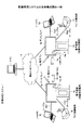
図1は、本実施形態の画像処理システムの全体構成図である。なお、図1では、説明を簡略化するために、2台の電子黒板2a,2b及びこれに付随する電子ペン4a,4b等を示しているだけであって、3台以上の電子黒板や電子ペン等を利用してもよい。電子黒板2a,2bは特許請求の範囲の情報処理装置の一例である。
<System overview>
FIG. 1 is an overall configuration diagram of an image processing system according to the present embodiment. In FIG. 1, only two electronic blackboards 2a and 2b and associated electronic pens 4a and 4b are shown to simplify the description. A pen or the like may be used. The electronic blackboards 2a and 2b are examples of the information processing apparatus in the claims.

図1に示されているように、画像処理システム1は、複数の電子黒板2a,2b、複数の電子ペン4a,4b、USBメモリ5a,5b、ノートPC(Personal Computer)6a,6b、テレビ(ビデオ)会議端末7a,7b、及びPC8を有する。また、電子黒板2a,2b、及びPC8は、通信ネットワーク9を介して通信可能に接続されている。更に、複数の電子黒板2a,2bには、それぞれディスプレイ3a,3bが設けられている
また、電子黒板2aには、電子ペン4aによって生じたイベント(ディスプレイ3aに電子ペン4aのペン先、又は、電子ペン4aのペン尻のタッチ)による描画された画像を、ディスプレイ3aに表示させることができる。なお、電子ペン4aだけでなく、ユーザの手Ha等によって生じたイベント(拡大、縮小、ページめくり等のジェスチャ)に基づいて、ディスプレイ3a上に表示されている画像を変更させることもできる。電子ペン4、手Hは特許請求の範囲のポインティングデバイスの一例である。
As shown in FIG. 1, the image processing system 1 includes a plurality of electronic blackboards 2a and 2b, a plurality of electronic pens 4a and 4b, USB memories 5a and 5b, notebook PCs (Personal Computers) 6a and 6b, a television ( Video) having conference terminals 7a, 7b and PC8. The electronic blackboards 2a and 2b and the PC 8 are connected via a communication network 9 so that they can communicate with each other. Further, the plurality of electronic blackboards 2a and 2b are respectively provided with displays 3a and 3b. Also, the electronic blackboard 2a has an event generated by the electronic pen 4a (the pen tip of the electronic pen 4a on the display 3a or An image drawn by touching the pen butt of the electronic pen 4a can be displayed on the display 3a. Note that the image displayed on the display 3a can be changed based not only on the electronic pen 4a but also on an event (a gesture such as enlargement, reduction, or page turning) generated by the user's hand Ha or the like. The electronic pen 4 and the hand H are examples of the pointing device in the claims.

また、電子黒板2aには、USBメモリ5aが接続可能であり、電子黒板2aはUSBメモリ5aからPDF等の電子ファイルを読み出したり、電子黒板2aはUSBメモリ5aに電子ファイルを記録することができる。また、電子黒板2aには、DisplayPort、DVI(Digital Visual Interface)、HDMI(登録商標)(High-Definition Multimedia Interface)及びVGA(Video Graphics Array)等の規格による通信が可能なケーブル10a1を介して、ノートPC6aが接続されている。そして、電子黒板2aでは、ディスプレイ3aに対する接触によってイベントを発生させ、このイベントを示すイベント情報を、マウスやキーボード等の入力装置からのイベントと同様に、ノートPC6aに送信する。同じく、電子黒板2aには、上記規格による通信が可能なケーブル10a2を介して、テレビ(ビデオ)会議端末7aが接続されている。なお、ノートPC6a、及びテレビ会議端末7aは、Bluetooth(登録商標)等の各種無線通信プロトコルに準拠した無線通信により、電子黒板2aと通信してもよい。   The electronic blackboard 2a can be connected to a USB memory 5a. The electronic blackboard 2a can read an electronic file such as PDF from the USB memory 5a, and the electronic blackboard 2a can record the electronic file in the USB memory 5a. . In addition, the electronic blackboard 2a is connected via a cable 10a1 capable of communication according to standards such as DisplayPort, DVI (Digital Visual Interface), HDMI (registered trademark) (High-Definition Multimedia Interface), and VGA (Video Graphics Array). A notebook PC 6a is connected. The electronic blackboard 2a generates an event by touching the display 3a, and transmits event information indicating the event to the notebook PC 6a in the same manner as an event from an input device such as a mouse or a keyboard. Similarly, a television (video) conference terminal 7a is connected to the electronic blackboard 2a via a cable 10a2 capable of communication according to the above-mentioned standards. Note that the notebook PC 6a and the video conference terminal 7a may communicate with the electronic blackboard 2a by wireless communication complying with various wireless communication protocols such as Bluetooth (registered trademark).

一方、電子黒板2bが設置されている他の拠点では、上記と同様に、ディスプレイ3bを備えた電子黒板2b、電子ペン4b、USBメモリ5b、ノートPC6b、テレビ会議端末7b、ケーブル10b1、ケーブル10b2が利用される。更に、ユーザの手Hb等によって生じたイベントに基づいて、ディスプレイ3b上に表示されている画像を変更させることもできる。   On the other hand, in the other bases where the electronic blackboard 2b is installed, the electronic blackboard 2b with the display 3b, the electronic pen 4b, the USB memory 5b, the notebook PC 6b, the video conference terminal 7b, the cable 10b1, and the cable 10b2 in the same manner as described above. Is used. Furthermore, the image displayed on the display 3b can be changed based on an event caused by the user's hand Hb or the like.

これにより、一の拠点で電子黒板2aのディスプレイ3a上に描画された画像は、他の拠点で電子黒板2bのディスプレイ3b上にも表示され、逆に他の拠点で電子黒板2bのディスプレイ3b上に描画された画像は、一の拠点で電子黒板2aのディスプレイ3a上に表示される。このように、画像処理システム1では、遠隔地において同じ画像を共有する遠隔共有処理を行うことができるため、遠隔地での会議等に用いると、非常に便利である。   Thereby, the image drawn on the display 3a of the electronic blackboard 2a at one base is also displayed on the display 3b of the electronic blackboard 2b at another base, and conversely on the display 3b of the electronic blackboard 2b at another base. The image drawn on is displayed on the display 3a of the electronic blackboard 2a at one base. As described above, the image processing system 1 can perform remote sharing processing for sharing the same image at a remote location, and thus is very convenient when used for a conference or the like at a remote location.

なお、以下では、複数の電子黒板のうち任意の電子黒板を示す場合には「電子黒板2」と示す。複数のディスプレイのうち任意のディスプレイを示す場合には「ディスプレイ3」と示す。複数の電子ペンのうち任意の電子ペンを示す場合には「電子ペン4」と示す。複数のUSBメモリのうち任意のUSBメモリを示す場合には「USBメモリ5」と示す。複数のノートPCのうち任意のノートPCを示す場合には「ノードPC6」と示す。複数のテレビ会議端末のうち任意のテレビ会議端末を示す場合には「テレビ会議端末7」と示す。また、複数のユーザの手のうち任意の手を示す場合には「手H」と示す。複数のケーブルのうち任意のケーブルを示す場合には「ケーブル10」と示す。   In the following, when an arbitrary electronic blackboard among the plurality of electronic blackboards is indicated, it is indicated as “electronic blackboard 2”. When an arbitrary display among a plurality of displays is shown, “display 3” is shown. When an arbitrary electronic pen among a plurality of electronic pens is indicated, it is indicated as “electronic pen 4”. When an arbitrary USB memory is indicated among the plurality of USB memories, it is indicated as “USB memory 5”. When an arbitrary notebook PC is indicated among the plurality of notebook PCs, it is indicated as “node PC 6”. When an arbitrary video conference terminal is indicated among the plurality of video conference terminals, it is indicated as “video conference terminal 7”. In addition, “hand H” is used when an arbitrary hand among the hands of a plurality of users is shown. When an arbitrary cable is indicated among the plurality of cables, it is indicated as “cable 10”.

また、本実施形態では、画像処理装置の一例として、電子黒板を説明するが、これに限るものではなく、画像処理装置の他の例として、電子看板(デジタルサイネージ)、スポーツや天気予報等で利用されるテレストレータ、又は、遠隔画像(映像)診断装置等であってもよい。また、情報処理端末の一例として、ノートPC6を説明するが、これに限るものではなく、情報処理端末の他の例として、デスクトップ型PCやタブレット型PC、スマートフォン、PDA、デジタルビデオカメラ、デジタルカメラ、ゲーム機等の画像フレームを供給可能な端末であってもよい。更に、通信ネットワークには、インターネット、LAN(Local Area Network)、携帯電話通信網等が含まれる。また、本実施形態では、記録媒体の一例として、USBメモリを説明するが、これに限るものではなく、記録媒体の他の例として、SDカード等の各種記録メディアであってもよい。   In the present embodiment, an electronic blackboard is described as an example of an image processing device. However, the present invention is not limited to this, and other examples of the image processing device include electronic signboards (digital signage), sports and weather forecasts. It may be a telestrator to be used, a remote image (video) diagnostic device, or the like. The notebook PC 6 will be described as an example of the information processing terminal, but is not limited thereto, and other examples of the information processing terminal include a desktop PC, a tablet PC, a smartphone, a PDA, a digital video camera, and a digital camera. A terminal capable of supplying image frames such as a game machine may be used. Further, the communication network includes the Internet, a LAN (Local Area Network), a mobile phone communication network, and the like. In this embodiment, a USB memory is described as an example of a recording medium. However, the present invention is not limited to this, and various recording media such as an SD card may be used as another example of the recording medium.

<電子黒板のハードウェア構成>
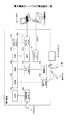
続いて、図2を用いて、本実施形態の電子黒板のハードウェア構成を説明する。なお、図2は、電子黒板のハードウェア構成図である。
<Hardware configuration of electronic blackboard>
Next, the hardware configuration of the electronic blackboard according to the present embodiment will be described with reference to FIG. FIG. 2 is a hardware configuration diagram of the electronic blackboard.

図2に示されているように、電子黒板2は、電子黒板2全体の動作を制御するCPU101、IPL等のCPU101の駆動に用いられるプログラムを記憶したROM102、CPU101のワークエリアとして使用されるRAM103、電子黒板2用のプログラム等の各種データを記憶するSSD204、通信ネットワーク9との通信を制御するネットワークコントローラ105、及び、USBメモリ5との通信を制御する外部記憶コントローラ106を備えている。   As shown in FIG. 2, the electronic blackboard 2 includes a CPU 101 that controls the operation of the electronic blackboard 2 as a whole, a ROM 102 that stores a program used to drive the CPU 101 such as an IPL, and a RAM 103 that is used as a work area of the CPU 101. And an SSD 204 for storing various data such as a program for the electronic blackboard 2, a network controller 105 for controlling communication with the communication network 9, and an external storage controller 106 for controlling communication with the USB memory 5.

また、電子黒板2は、ノートPC6がディスプレイに表示している静止画または動画を取り込むキャプチャデバイス111、グラフィクスを専門に扱うGPU(Graphics Processing Unit)112、及び、GPUからの出力画像をディスプレイ3やテレビ会議端末7へ出力するために画面表示の制御及び管理を行うディスプレイコントローラ113を備えている。   The electronic blackboard 2 also includes a capture device 111 that captures still images or moving images displayed on the display of the notebook PC 6, a GPU (Graphics Processing Unit) 112 that specializes in graphics, and an output image from the GPU on the display 3 or A display controller 113 that controls and manages screen display for output to the video conference terminal 7 is provided.

更に、電子黒板2は、接触センサ115の処理を制御するセンサコントローラ114、ディスプレイ3上に電子ペン4やユーザの手H等が接触したことを検知する接触センサ115を備えている。この接触センサ115は、赤外線遮断方式による座標の入力及び座標の検出を行う。この座標の入力及び座標の検出する方法は、ディスプレイ3の上側両端部に設置された2つ受発光装置(不図示)が、ディスプレイ3に平行して複数の赤外線を放射し、ディスプレイ3の周囲に設けられた反射部材によって反射されて、受光素子が放射した光の光路と同一の光路上を戻って来る光を受光する方法である。接触センサ115は、物体によって遮断された2つの受発光装置が放射した赤外線のID(Identification)をセンサコントローラ114に出力し、センサコントローラ114が、物体の接触位置である座標位置を特定する。なお、以下に示す全てのIDは、識別情報の一例である。   The electronic blackboard 2 further includes a sensor controller 114 that controls processing of the contact sensor 115 and a contact sensor 115 that detects that the electronic pen 4 or the hand H of the user touches the display 3. The contact sensor 115 performs coordinate input and coordinate detection by an infrared ray blocking method. In this coordinate input and coordinate detection method, two light emitting / receiving devices (not shown) installed at both upper ends of the display 3 emit a plurality of infrared rays in parallel with the display 3, This is a method of receiving light that is reflected by the reflecting member provided on the light source and returns on the same optical path as the light path of the light emitted by the light receiving element. The contact sensor 115 outputs infrared ID (Identification) emitted by the two light receiving and emitting devices blocked by the object to the sensor controller 114, and the sensor controller 114 identifies the coordinate position that is the contact position of the object. All IDs shown below are examples of identification information.

また、接触センサ115としては、赤外線遮断方式に限らず、静電容量の変化を検知することにより接触位置を特定する静電容量方式のタッチパネル、対向する2つの抵抗膜の電圧変化によって接触位置を特定する抵抗膜方式のタッチパネル、接触物体が表示部に接触することによって生じる電磁誘導を検知して接触位置を特定する電磁誘導方式のタッチパネルなどの種々の検出手段を用いてもよい。   In addition, the contact sensor 115 is not limited to the infrared blocking method, and a capacitive touch panel that identifies a contact position by detecting a change in capacitance, or a contact position determined by a voltage change between two opposing resistance films. Various detection means such as a resistance film type touch panel to be identified and an electromagnetic induction type touch panel to identify a contact position by detecting electromagnetic induction caused by contact of a contact object with the display unit may be used.

また、電子黒板2は、電子ペンコントローラ116を備えている。この電子ペンコントローラ116は、電子ペン4と通信することで、ディスプレイ3へのペン先のタッチやペン尻のタッチの有無を判断する。なお、電子ペンコントローラ116が、電子ペン4のペン先及びペン尻だけでなく、電子ペン4のユーザが握る部分や、その他の電子ペンの部分のタッチの有無を判断するようにしてもよい。   The electronic blackboard 2 includes an electronic pen controller 116. This electronic pen controller 116 communicates with the electronic pen 4 to determine whether or not there is a pen tip touch or a pen butt touch on the display 3. It should be noted that the electronic pen controller 116 may determine whether or not the user grips the part of the electronic pen 4 as well as the other electronic pen part, as well as the pen tip and the bottom of the electronic pen 4.

更に、電子黒板2は、CPU101、ROM102、RAM103、SSD104、ネットワークコントローラ105、外部記憶コントローラ106、キャプチャデバイス111、GPU112、センサコントローラ114、及び電子ペンコントローラ116を図2に示されているように電気的に接続するためのアドレスバスやデータバス等のバスライン120を備えている。   Further, the electronic blackboard 2 includes the CPU 101, ROM 102, RAM 103, SSD 104, network controller 105, external storage controller 106, capture device 111, GPU 112, sensor controller 114, and electronic pen controller 116 as shown in FIG. A bus line 120 such as an address bus or a data bus for connection is provided.

なお、電子黒板2用のプログラムは、CD−ROM等のコンピュータで読み取り可能な記録媒体に記録して流通させるようにしてもよい。   The program for the electronic blackboard 2 may be recorded and distributed on a computer-readable recording medium such as a CD-ROM.

<電子黒板の機能構成>
続いて、図3乃至図20を用いて、電子黒板の機能構成について説明する。なお、先ずは、図3を用いて、電子黒板2の全体的な機能構成について説明する。図3は、電子黒板の機能ブロック図である。
<Functional configuration of electronic blackboard>
Next, the functional configuration of the electronic blackboard will be described with reference to FIGS. First, the overall functional configuration of the electronic blackboard 2 will be described with reference to FIG. FIG. 3 is a functional block diagram of the electronic blackboard.

電子黒板2は、図2に示されているハードウェア構成及びプログラムによって、図3にされている各機能構成を有する。電子黒板2は、最初に遠隔共有処理を開始する「主催装置」となり得ると共に、既に開始されている遠隔共有処理に後から参加する「参加装置」にもなり得る。また、電子黒板2は、主要な機能として、クライアント機20及びサーバ機90を有している。即ち、電子黒板2の1台の筐体内に、クライアント機20及びサーバ機90が含まれている。クライアント部20及びサーバ部90は、電子黒板2の1台の筐体内で実現される機能である。そして、電子黒板2が主催装置となる場合には、この電子黒板2では、クライアント部20とサーバ部90が実現される。また、電子黒板2が参加装置となる場合には、この電子黒板2では、クライアント部20は実現されるが、サーバ部90は実現されない。即ち、図1において、電子黒板2aが主催装置で、電子黒板2bが参加装置となる場合、電子黒板2aのクライアント部20は、同じ電子黒板2a内に実現されたサーバ部90を介して、他の電子黒板2bのクライアント部20と通信を行う。一方、電子黒板2bのクライアント部20は、他の電子黒板2a内に実現されたサーバ部90を介して、他の電子黒板2aのクライアント部と通信を行う。   The electronic blackboard 2 has the functional configurations shown in FIG. 3 by the hardware configuration and program shown in FIG. The electronic blackboard 2 can be a “host device” that starts the remote sharing process first, and can also be a “participating device” that participates in the remote sharing process that has already started. The electronic blackboard 2 includes a client machine 20 and a server machine 90 as main functions. That is, the client machine 20 and the server machine 90 are included in one casing of the electronic blackboard 2. The client unit 20 and the server unit 90 are functions realized in one housing of the electronic blackboard 2. When the electronic blackboard 2 is a hosting device, the electronic blackboard 2 implements the client unit 20 and the server unit 90. Further, when the electronic blackboard 2 is a participating device, in the electronic blackboard 2, the client unit 20 is realized, but the server unit 90 is not realized. That is, in FIG. 1, when the electronic blackboard 2a is the hosting device and the electronic blackboard 2b is the participating device, the client unit 20 of the electronic blackboard 2a receives the other via the server unit 90 realized in the same electronic blackboard 2a. Communicate with the client unit 20 of the electronic blackboard 2b. On the other hand, the client unit 20 of the electronic blackboard 2b communicates with the client units of the other electronic blackboard 2a via the server unit 90 realized in the other electronic blackboard 2a.

〔クライアント機20の機能構成〕
続いて、主に図3乃至図5を用いて、クライアント機20の機能構成について説明する。クライアント機20は、映像取得部21、座標検知部22、自動調整部23、接触検知部24、イベント振分部25、操作処理部26、ジェスチャ処理部27、映像重畳部28、画像処理部30、及び通信制御部60を有する。
[Functional configuration of client machine 20]
Subsequently, the functional configuration of the client machine 20 will be described mainly using FIGS. 3 to 5. The client machine 20 includes a video acquisition unit 21, a coordinate detection unit 22, an automatic adjustment unit 23, a contact detection unit 24, an event distribution unit 25, an operation processing unit 26, a gesture processing unit 27, a video superimposition unit 28, and an image processing unit 30. And a communication control unit 60.

このうち、映像取得部21は、ケーブル10に接続されたノートPC6等の映像出力機器の出力映像を取得する。映像取得部21は、映像出力機器(ノートPC6等)から画像信号を受信すると、この画像信号を解析して、この画像信号によって形成される映像出力機器の表示画像である画像フレームの解像度や、この画像フレームの更新頻度などの画像情報を導出し、画像取得部31に出力する。   Among these, the video acquisition unit 21 acquires an output video of a video output device such as a notebook PC 6 connected to the cable 10. When the video acquisition unit 21 receives an image signal from a video output device (such as a notebook PC 6), the video acquisition unit 21 analyzes the image signal, and the resolution of an image frame that is a display image of the video output device formed by the image signal, Image information such as the update frequency of the image frame is derived and output to the image acquisition unit 31.

座標検知部22は、ディスプレイ3上でユーザによって生じたイベント(ディスプレイ3上にユーザの手Hがタッチされた動作等)の座標位置を検出する。また、座標検知部22は、タッチされた面積も検出する。   The coordinate detection unit 22 detects the coordinate position of an event (such as an operation in which the user's hand H is touched on the display 3) generated by the user on the display 3. The coordinate detection unit 22 also detects the touched area.

自動調整部23は、電子黒板2の起動時に起動され、接触センサ115が座標検知部22に適切な値を出力できるように、接触センサ115の光センサ方式におけるセンサーカメラの画像処理のパラメータを調整する。   The automatic adjustment unit 23 is activated when the electronic blackboard 2 is activated, and adjusts the image processing parameters of the sensor camera in the optical sensor method of the contact sensor 115 so that the contact sensor 115 can output an appropriate value to the coordinate detection unit 22. To do.

接触検知部24は、ユーザによって生じたイベント(ディスプレイ3上に電子ペン4のペン先又は電子ペン3のペン尻が押下(タッチ)された動作等)を検出する。   The contact detection unit 24 detects an event (such as an operation in which the pen tip of the electronic pen 4 or the pen tip of the electronic pen 3 is pressed (touched) on the display 3).

イベント振分部25は、座標検知部22によって検知されたイベントの座標位置と接触検知部24によって検出された検出結果を、ストローク描画、UI操作、及びジェスチャ操作の各イベントに振り分ける。   The event distribution unit 25 distributes the coordinate position of the event detected by the coordinate detection unit 22 and the detection result detected by the contact detection unit 24 to each event of stroke drawing, UI operation, and gesture operation.

ここで、「ストローク描画」は、ディスプレイ3上に図20に示されている後述のストローク画像(B)が表示されている場合に、ユーザがディスプレイ3上で電子ペン4を押下し、この押下した状態で電子ペン4を移動させ、最終的にディスプレイ3上から電子ペン4を離すまでのイベントである。このストローク描画により、例えば、アルファベット「S」や「T」等がディスプレイ3上に描画される。なお、この「ストローク描画」には、画像を描画するだけでなく、既に描画された画像を削除したり、描画された画像を編集するイベントも含まれる。   Here, “stroke drawing” is performed when the user presses the electronic pen 4 on the display 3 when a stroke image (B) described later shown in FIG. 20 is displayed on the display 3. In this state, the electronic pen 4 is moved and finally the electronic pen 4 is released from the display 3. By this stroke drawing, for example, alphabets “S” and “T” are drawn on the display 3. The “stroke drawing” includes not only drawing an image but also an event of deleting an already drawn image or editing a drawn image.

「UI操作」は、ディスプレイ3上に図20に示されている後述のUI画像(A)が表示されている場合に、ユーザが電子ペン4又は手Hによって所定の位置を押下したイベントである。このUI操作により、例えば、電子ペン4により描画される線の色や幅等が設定される。   The “UI operation” is an event in which the user presses a predetermined position with the electronic pen 4 or the hand H when a UI image (A) described later shown in FIG. 20 is displayed on the display 3. . By this UI operation, for example, the color or width of a line drawn by the electronic pen 4 is set.

「ジェスチャ操作」は、ディスプレイ3上に図20に示されている後述のストローク画像(B)が表示されている場合に、ユーザが手Hでディスプレイ3上をタッチしたり移動させるイベントである。このジェスチャ操作により、例えば、ユーザがディスプレイ3に手Hをタッチさせた状態で手Hを移動させることで、画像の拡大(若しくは縮小)、表示領域の変更、又は、ページ切り換え等を行うことができる。   “Gesture operation” is an event in which the user touches or moves the display 3 with the hand H when a stroke image (B) described later shown in FIG. 20 is displayed on the display 3. By this gesture operation, for example, by moving the hand H while the user touches the display 3 with the hand H, the image can be enlarged (or reduced), the display area can be changed, or the page can be switched. it can.

操作処理部26は、イベント振分部25によってUI操作と判断されたものから、イベントが発生されたUIの要素に従って、各種操作を実行する。このUIの要素としては、例えば、ボタン、リスト、チェックボックス、テキストボックスが挙げられる。ジェスチャ処理部27は、イベント振分部25によってジェスチャ操作と判断されたものに対応した操作を実行する。   The operation processing unit 26 executes various operations according to the UI element in which the event is generated, from what is determined as the UI operation by the event distribution unit 25. Examples of the UI element include a button, a list, a check box, and a text box. The gesture processing unit 27 performs an operation corresponding to what is determined as a gesture operation by the event distribution unit 25.

操作処理部26が有する制限受付部261は、例えば図17の機能制限リストの作成画面に対するユーザの操作を受け付け、機能制限リストを作成する。機能制限リストの作成画面は例えばUI画像生成部33が表示する。   The restriction receiving unit 261 included in the operation processing unit 26 receives, for example, a user operation on the function restriction list creation screen illustrated in FIG. 17 and creates a function restriction list. For example, the UI image generation unit 33 displays the function restriction list creation screen.

映像重畳部28は、後述の表示重畳部36で重畳された画像を映像として映像出力器器(ディスプレイ3等)に対して表示する。また、映像重畳部28は、映像出力機器(ノートPC6等)からの映像に対して、他の映像出力機器(テレビ会議端末7等)から送られて来た映像をピクチャ・イン・ピクチャする。更に、映像重畳部28は、ピクチャ・イン・ピクチャされてディスプレイ3の一部に表示された映像を、ディスプレイ3の全体に表示させるための切り替えを行う。   The video superimposing unit 28 displays the image superimposed by the display superimposing unit 36 described later as a video on the video output device (display 3 or the like). In addition, the video superimposing unit 28 performs picture-in-picture of the video sent from another video output device (such as the video conference terminal 7) with respect to the video from the video output device (such as the notebook PC 6). Further, the video superimposing unit 28 performs switching for displaying the video that is picture-in-picture and displayed on a part of the display 3 on the entire display 3.

画像処理部30は、各画像レイヤの重畳処理等を行う。詳細は図20にて説明する。画像処理部30は、画像取得部31、ストローク処理部32、UI画像生成部33、背景生成部34、レイアウト管理部35、表示重畳部36、ページ処理部37、ファイル処理部40、ページデータ記憶部300、及び遠隔ライセンス管理テーブル310を有している。   The image processing unit 30 performs superimposition processing of each image layer. Details will be described with reference to FIG. The image processing unit 30 includes an image acquisition unit 31, a stroke processing unit 32, a UI image generation unit 33, a background generation unit 34, a layout management unit 35, a display superimposition unit 36, a page processing unit 37, a file processing unit 40, and page data storage. Section 300 and a remote license management table 310.

このうち、画像取得部31は、映像取得部21で取得された映像から、各フレームを画像として取得する。この画像は、図20に示されている映像出力機器(ノートPC6等)からの出力画像(C)に相当する。   Among these, the image acquisition unit 31 acquires each frame as an image from the video acquired by the video acquisition unit 21. This image corresponds to an output image (C) from the video output device (notebook PC 6 or the like) shown in FIG.

ストローク処理部32は、イベント振分部25によって割り振られたストローク描画に係るイベントに基づいて、画像を描画したり、描画された画像を削除したり、描画された画像を編集する。このストローク描画による画像は、図20に示されているストローク画像(B)に相当する。また、このストローク等に基づいた画像の描画、削除、編集の各結果は、後述の操作データとして、操作データ記憶部840に記憶される。   The stroke processing unit 32 draws an image, deletes the drawn image, or edits the drawn image based on the event related to the stroke drawing assigned by the event distribution unit 25. The image by this stroke drawing corresponds to the stroke image (B) shown in FIG. In addition, the results of drawing, deleting, and editing an image based on the stroke and the like are stored in the operation data storage unit 840 as operation data described later.

UI画像生成部33は、電子黒板2に予め設定されているUI(ユーザインターフェース)画像を生成する。このUI画像は、図20に示されているUI画像(A)に相当する。   The UI image generation unit 33 generates a UI (user interface) image set in advance on the electronic blackboard 2. This UI image corresponds to the UI image (A) shown in FIG.

UI画像生成部33が有する操作制限部331は、操作制限リストに応じて操作が制限されたUI画像を作成する。操作が制限されるとは、制限された操作に対応するアイコンが表示されないこと又は表示されても選択できないことなどをいう。   The operation restriction unit 331 included in the UI image generation unit 33 creates a UI image whose operation is restricted according to the operation restriction list. The restriction of the operation means that an icon corresponding to the restricted operation is not displayed or cannot be selected even if displayed.

背景生成部34は、ページ処理部37がページデータ記憶部300から読み出したページデータのうちのメディアデータを、ページ処理部37から受信する。背景生成部34は、この受信したメディアデータを表示重畳部36に出力する。また、このメディアデータによる画像は、図20に示されている背景画像(D)に相当する。背景画像(D)のパターンは、無地、グリッド表示等である。   The background generation unit 34 receives media data from the page data read from the page data storage unit 300 by the page processing unit 37 from the page processing unit 37. The background generation unit 34 outputs the received media data to the display superimposing unit 36. The image based on the media data corresponds to the background image (D) shown in FIG. The pattern of the background image (D) is plain or grid display.

レイアウト管理部35は、表示重畳部36に対して、画像取得部31、ストローク処理部32、及びUI画像生成部33(又は背景生成部34)から出力された各画像のレイアウトを示すレイアウト情報を管理している。これにより、レイアウト管理部35は、表示重畳部36に対して、出力画像(C)及びストローク画像(B)を、UI画像(A)及び背景画像(D)中のどの位置に表示させるか又は非表示にさせるかを指示することができる。   The layout management unit 35 provides layout information indicating the layout of each image output from the image acquisition unit 31, the stroke processing unit 32, and the UI image generation unit 33 (or the background generation unit 34) to the display superimposing unit 36. I manage. Thereby, the layout management unit 35 causes the display superimposing unit 36 to display the output image (C) and the stroke image (B) in the UI image (A) and the background image (D). It is possible to instruct whether to hide.

表示重畳部36は、レイアウト管理部35から出力されたレイアウト情報に基づき、画像取得部31、ストローク処理部32、UI画像生成部33、及び背景生成部34から出力された各画像のレイアウトを行う。   The display superimposing unit 36 performs layout of each image output from the image acquisition unit 31, the stroke processing unit 32, the UI image generation unit 33, and the background generation unit 34 based on the layout information output from the layout management unit 35. .

ページ処理部37は、ストローク画像(B)のデータと出力画像(C)のデータを、1つのページデータにまとめてページデータ記憶部300に記憶する。ストローク画像(B)のデータは、図6に示されているストローク配列データIDで示されるストローク配列データ(各ストロークデータ)として、ページデータの一部を成す。出力画像(C)のデータは、図6に示されているメディアデータIDで示されているメディアデータとして、ページデータの一部を成す。そして、このメディアデータは、ページデータ記憶部300から読み出されると、背景画像(D)のデータとして取り扱われる。
また、ページ処理部37は、一旦記憶されたページデータのうちのメディアデータを、背景生成部34を介して表示重畳部36に送信することで、映像重畳部28が背景画像(D)をディスプレイ3に再表示させることができる。また、ページ処理部37は、ページデータのうちのストローク配列データ(各ストロークデータ)を、ストローク処理部32に戻すことで、ストロークの再編集ができる状態にすることができる。更に、ページ処理部37は、ページデータを削除したり複製することもできる。
即ち、ページ処理部37がページデータ記憶部300にページデータを記憶する時点でディスプレイ3上に表示されている出力画像(C)のデータは、一旦、ページデータ記憶部300に記憶され、その後にページデータ記憶部300から読み出される際には、背景画像(D)を示すメディアデータとして読みされる。そして、ページ処理部37は、ページデータ記憶部300から読み出したページデータのうち、ストローク画像(B)を示すストローク配列データを、ストローク処理部32に出力する。また、ページ処理部37は、ページデータ記憶部300から読み出したページデータのうち、背景画像(D)を示すメディアデータを、背景生成部34に出力する。
The page processing unit 37 stores the data of the stroke image (B) and the data of the output image (C) in one page data and stores them in the page data storage unit 300. The data of the stroke image (B) forms part of page data as stroke arrangement data (each stroke data) indicated by the stroke arrangement data ID shown in FIG. The data of the output image (C) forms part of the page data as the media data indicated by the media data ID shown in FIG. Then, when this media data is read from the page data storage unit 300, it is handled as data of the background image (D).
Further, the page processing unit 37 transmits the media data of the once stored page data to the display superimposing unit 36 via the background generating unit 34 so that the video superimposing unit 28 displays the background image (D). 3 can be displayed again. The page processing unit 37 can return the stroke arrangement data (each stroke data) in the page data to the stroke processing unit 32 so that the stroke can be re-edited. Further, the page processing unit 37 can delete or duplicate page data.
That is, the data of the output image (C) displayed on the display 3 when the page processing unit 37 stores the page data in the page data storage unit 300 is temporarily stored in the page data storage unit 300 and then When read from the page data storage unit 300, it is read as media data indicating the background image (D). Then, the page processing unit 37 outputs stroke arrangement data indicating the stroke image (B) among the page data read from the page data storage unit 300 to the stroke processing unit 32. Further, the page processing unit 37 outputs media data indicating the background image (D) among the page data read from the page data storage unit 300 to the background generation unit 34.

表示重畳部36は、画像取得部31からの出力画像(C)、ストローク処理部32からのストローク画像(B)、UI画像生成部33からのUI画像(A)、及び、背景生成部34からの背景画像(D)を、レイアウト管理部35によって指定されたレイアウトに従って重畳する。これにより、図20に示されているように、各画像が重なってもユーザが見える順に、UI画像(A)、ストローク画像(B)、出力画像(C)、及び背景画像(D)の各レイアの構成となっている。   The display superimposing unit 36 includes an output image (C) from the image acquisition unit 31, a stroke image (B) from the stroke processing unit 32, a UI image (A) from the UI image generation unit 33, and a background generation unit 34. The background image (D) is superimposed according to the layout designated by the layout management unit 35. Accordingly, as shown in FIG. 20, each of the UI image (A), the stroke image (B), the output image (C), and the background image (D) is displayed in the order in which the user can see even if the images overlap. It has Leia composition.

また、表示重畳部36は、図20に示されている画像(C)と画像(D)を切り替えて画像(A)及び画像(B)に対して排他的に重畳することも可能である。例えば、当初、画像(A)、画像(B)及び画像(C)が表示されている状態で、電子黒板2と映像出力機器(ノートPC6等)との間のケーブル10が抜かれた場合には、レイアウト管理部35の指定によって、描画(C)を重畳対象から外すことができる。また、表示重畳部36は、表示の拡大、表示の縮小、表示領域の移動処理も行う。   Further, the display superimposing unit 36 can also superimpose the image (A) and the image (B) exclusively by switching the image (C) and the image (D) shown in FIG. For example, when the cable 10 between the electronic blackboard 2 and the video output device (notebook PC 6 or the like) is disconnected while the image (A), the image (B), and the image (C) are initially displayed. The drawing (C) can be removed from the superimposition target as specified by the layout management unit 35. The display superimposing unit 36 also performs display enlargement, display reduction, and display area movement processing.

ページデータ記憶部300は、図6に示されているようなページデータを記憶する。図6は、ページデータを示す概念図である。ページデータは、ディスプレイ3に表示される1ページ分のデータ(ストロークデータ及び画像データ)である。なお、ページデータに含まれるパラメータの種類が多いため、ここでは、図6乃至9に分けて、ページデータの内容を説明する。   The page data storage unit 300 stores page data as shown in FIG. FIG. 6 is a conceptual diagram showing page data. The page data is data for one page (stroke data and image data) displayed on the display 3. Since there are many types of parameters included in the page data, the contents of the page data will be described here separately in FIGS.

ページデータ記憶部300は、図6に示されているようなページデータを記憶する。図6は、ページデータを示す概念図である。ページデータは、ディスプレイ3に表示される1ページ分のデータ(ストローク配列データ(各ストロークデータ)及びメディアデータ)である。なお、ページデータに含まれるパラメータの種類が多いため、ここでは、図6乃至9に分けて、ページデータの内容を説明する。
ページデータは、図6に示されているように、任意の1ページを識別するためのページデータID、このページの表示を開始した時刻を示す開示時刻、ストロークやジェスチャ等によるページの内容の書き換えが行われなくなった時刻を示す終了時刻、電子ペン4やユーザの手Hによるストロークによって生じたストローク配列データを識別するためのストローク配列データID、及びメディアデータを識別するためのメディアデータIDが関連付けて記憶されている。ストローク配列データは、後述の図20に示されているストローク画像(B)がディスプレイ3上に表示されるためのデータである。メディアデータは、後述の16に示されている背景画像(D)がディスプレイ3上に表示されるためのデータである。
The page data storage unit 300 stores page data as shown in FIG. FIG. 6 is a conceptual diagram showing page data. The page data is data for one page displayed on the display 3 (stroke arrangement data (each stroke data) and media data). Since there are many types of parameters included in the page data, the contents of the page data will be described here separately in FIGS.
As shown in FIG. 6, the page data includes a page data ID for identifying an arbitrary page, a disclosure time indicating the start time of display of this page, and rewriting of the contents of the page by a stroke, a gesture, or the like. Are associated with the end time indicating the time when the operation is stopped, the stroke arrangement data ID for identifying the stroke arrangement data generated by the stroke of the electronic pen 4 or the user's hand H, and the media data ID for identifying the media data. Is remembered. The stroke arrangement data is data for displaying a stroke image (B) shown in FIG. The media data is data for displaying a background image (D) shown in 16 described later on the display 3.

このようなページデータにより、例えば、ユーザが電子ペン4によってアルファベット「S」を描く場合は一筆書きとなるため、ストロークデータIDが1つで一文字のアルファベット[S]が示される。ところが、ユーザが電子ペン4によって、アルファベット「T」を描く場合、二筆書きとなるため、ストロークデータIDが2つで一文字のアルファベット「T」が示されることになる。   With such page data, for example, when the user draws the alphabet “S” with the electronic pen 4, the stroke is written in one stroke, and therefore, one stroke data ID is displayed and one letter of the alphabet [S] is indicated. However, when the user draws the alphabet “T” with the electronic pen 4, it is written with two strokes, so that one stroke of the alphabet “T” is indicated by two stroke data IDs.

また、ストローク配列データは、図7に示されているように詳細な情報を示している。図7は、ストローク配列データを示す概念図である。図7に示されているように、1つのストローク配列データは、複数のストロークデータによって表される。そして、1つのストロークデータは、このストロークデータを識別するためのストロークデータID、1つのストロークの書き始めの時刻を示す開始時刻、1つのストロークの書き終わりの時刻を示す終了時刻、ストロークの色、ストロークの幅、及び、ストロークの通過点の配列を識別するための座標配列データIDを示している。   The stroke arrangement data shows detailed information as shown in FIG. FIG. 7 is a conceptual diagram showing stroke arrangement data. As shown in FIG. 7, one stroke arrangement data is represented by a plurality of stroke data. One stroke data includes a stroke data ID for identifying the stroke data, a start time indicating the start time of writing one stroke, an end time indicating the end time of writing one stroke, the color of the stroke, A stroke width and coordinate array data ID for identifying an array of stroke passing points are shown.

更に、この座標配列データは、図8に示されているように詳細な情報を示している。図8は、座標配列データを示す概念図である。図8に示されているように、座標配列データは、ディスプレイ3上の1点(X座標値、Y座標値)、この1点を通過したときのストロークの開示時刻からの差分の時刻(ms)、及び、この1点における電子ペン4の筆圧の各情報を示している。   Further, the coordinate array data shows detailed information as shown in FIG. FIG. 8 is a conceptual diagram showing coordinate array data. As shown in FIG. 8, the coordinate array data includes one point (X coordinate value, Y coordinate value) on the display 3, and a time difference (ms from the disclosure time of the stroke when the one point is passed) ) And writing pressure information of the electronic pen 4 at this one point.

即ち、図8に示されている1点の集まりが、図7に示されている1つの座標配列データで示されている。例えば、ユーザが電子ペン4によって、アルファベット「S」を描く場合、一筆書きとなるが、「S」を描き終えるまでに、複数の通過点を通過するため、座標配列データは、これら複数の通過点の情報を示している。   That is, the collection of one point shown in FIG. 8 is shown by one coordinate array data shown in FIG. For example, when the user draws the alphabet “S” with the electronic pen 4, it is drawn with a single stroke, but passes through a plurality of passing points before the drawing of “S”. Point information is shown.

また、図6に示されているページデータのうちのメディアデータは、図9に示されているように詳細な情報を示している。図9は、メディアデータを示す概念図である。図9に示されているように、メディアデータは、図6に示されているページデータにおけるメディアデータID、メディアデータのデータ種類、ページ処理部37からページデータ記憶部300にページデータが記憶された記録時刻、ページデータによってディスプレイ3上に表示される画像の位置(X座標値、Y座標値)及び画像のサイズ(幅、高さ)、並びにメディアデータの内容を示すデータが関連付けられて示されている。このうち、ページデータによってディスプレイ3上に表示される画像の位置は、ディスプレイ3の左上端の座標を(X座標値,Y座標値)=(0,0)とした場合に、ページデータによって表示される画像の左上端の位置を示している。   Further, the media data in the page data shown in FIG. 6 shows detailed information as shown in FIG. FIG. 9 is a conceptual diagram showing media data. As shown in FIG. 9, the media data is stored in the page data storage unit 300 from the page processing unit 37, the media data ID in the page data shown in FIG. The recording time, the position of the image displayed on the display 3 by the page data (X coordinate value, Y coordinate value), the size of the image (width, height), and data indicating the contents of the media data are shown in association with each other. Has been. Among these, the position of the image displayed on the display 3 by the page data is displayed by the page data when the coordinates of the upper left corner of the display 3 are (X coordinate value, Y coordinate value) = (0, 0). The position of the upper left corner of the image to be displayed is shown.

図3に戻り、遠隔ライセンス管理テーブル310は、遠隔共有処理を実行するために必要なライセンスデータを管理する。この遠隔ライセンス管理テーブル310では、図10に示されているように、電子黒板2のプロダクトID、認証に用いられるライセンスID、及びライセンスの有効期限が関連付けて管理されている。   Returning to FIG. 3, the remote license management table 310 manages license data necessary for executing the remote sharing process. In the remote license management table 310, as shown in FIG. 10, the product ID of the electronic blackboard 2, the license ID used for authentication, and the expiration date of the license are managed in association with each other.

(ファイル処理部40の機能構成)
続いて、図4を用いて、図3に示されているファイル処理部40の機能構成を説明する。なお、図4は、ファイル処理部の機能ブロック図である。以下では、最初に遠隔共有処理を開始する電子黒板2を「主催装置」、既に開始されている遠隔共有処理に後から参加する電子黒板2を「参加装置」と称して説明する。
(Functional configuration of the file processing unit 40)
Next, the functional configuration of the file processing unit 40 shown in FIG. 3 will be described with reference to FIG. FIG. 4 is a functional block diagram of the file processing unit. Hereinafter, the electronic blackboard 2 that starts the remote sharing process first will be referred to as “host device”, and the electronic blackboard 2 that will participate in the remote sharing processing that has already been started will be referred to as “participating device”.

ファイル処理部40は、リカバリ処理部41、ファイル入力部42a、ファイル出力部42b、ファイル変換部43、ファイル送信部44、アドレス帳入力部45、バックアップ処理部46、バックアップ出力部47、設定管理部48、設定ファイル入力部49a、及び設定ファイル出力部49bを有している。更に、ファイル処理部40は、アドレス帳管理テーブル410、バックアップデータ記憶部420、設定ファイル記憶部430、及び接続先管理テーブル440を有している。   The file processing unit 40 includes a recovery processing unit 41, a file input unit 42a, a file output unit 42b, a file conversion unit 43, a file transmission unit 44, an address book input unit 45, a backup processing unit 46, a backup output unit 47, and a setting management unit. 48, a setting file input unit 49a, and a setting file output unit 49b. Furthermore, the file processing unit 40 includes an address book management table 410, a backup data storage unit 420, a setting file storage unit 430, and a connection destination management table 440.

このうち、リカバリ処理部41は、電子黒板2が異常終了した後に、異常終了を検知し、未保存のページデータを復旧する。例えば、正常終了の場合は、ページデータがPDFファイルとしてファイル処理部40を介してUSB5に記録されるが、電源がダウンした等の異常終了の場合は、ページデータがページデータ記憶部300に記録されたままになっている。そのため、再び、電源オンになった際に、リカバリ処理部41は、ページデータ記憶部300からページデータを読み出すことで復旧させる。   Among these, the recovery processing unit 41 detects the abnormal end after the electronic blackboard 2 ends abnormally, and recovers the unsaved page data. For example, in the case of a normal end, the page data is recorded as a PDF file on the USB 5 via the file processing unit 40, but in the case of an abnormal end such as when the power is down, the page data is recorded in the page data storage unit 300. Has been done. Therefore, when the power is turned on again, the recovery processing unit 41 recovers by reading the page data from the page data storage unit 300.

ファイル入力部42aは、USBメモリ5から、PDFファイルを読み込み、各ページをページデータとしてページデータ記憶部300に記憶する。ファイル変換部43は、ページデータ記憶部300に記憶されているページデータを、PDF形式のファイルに変換する。   The file input unit 42a reads a PDF file from the USB memory 5 and stores each page in the page data storage unit 300 as page data. The file conversion unit 43 converts the page data stored in the page data storage unit 300 into a PDF format file.

ファイル出力部42bは、ファイル変換部43によって出力されたPDFファイルをUSBメモリ5に記録する。ファイル送信部44は、ファイル変換部43によって生成されたPDFファイルを、電子メールに添付して送信する。   The file output unit 42 b records the PDF file output by the file conversion unit 43 in the USB memory 5. The file transmission unit 44 transmits the PDF file generated by the file conversion unit 43 by attaching it to an electronic mail.

このファイルの送信先は、表示重畳部36によってディスプレイ3上にアドレス帳管理テーブル410の内容を表示し、ファイル送信部44がユーザによるタッチパネル等の入力装置の操作により、宛先の選択を受け付けることによって決定される。アドレス帳管理テーブル410には、図11に示されているように、宛先の名前及び宛先の電子メールのメールアドレスが関連付けて管理されている。また、ファイル送信部44が、ユーザによるタッチパネル等の入力装置の操作により、宛先としてのメールアドレスの入力を受け付けることもできる。   The transmission destination of the file is displayed by displaying the contents of the address book management table 410 on the display 3 by the display superimposing unit 36, and the file transmitting unit 44 accepts the selection of the destination by the operation of the input device such as a touch panel by the user. It is determined. In the address book management table 410, as shown in FIG. 11, the name of the destination and the mail address of the destination e-mail are managed in association with each other. Further, the file transmission unit 44 can accept an input of a mail address as a destination by an operation of an input device such as a touch panel by the user.

アドレス帳入力部45は、USBメモリ5から電子メールアドレスの一覧ファイルを読み込み、アドレス帳管理テーブル410に管理する。   The address book input unit 45 reads a list file of e-mail addresses from the USB memory 5 and manages it in the address book management table 410.

バックアップ処理部46は、ファイル出力部42bによって出力されたファイルや、ファイル送信部44によって送信されたファイルを、バックアップデータ記憶部420に記憶することでバックアップする。なお、ユーザがバックアップ設定しない場合は、バックアップの処理は行われない。バックアップデータは、図12に示されているように、PDF形式で記憶される。   The backup processing unit 46 performs backup by storing the file output by the file output unit 42 b and the file transmitted by the file transmission unit 44 in the backup data storage unit 420. If the user does not set backup, backup processing is not performed. The backup data is stored in the PDF format as shown in FIG.

バックアップ出力部47は、バックアップされたファイルをUSBメモリ5に記憶する。この記憶には、ユーザによるタッチパネル等の入力装置の操作により、セキュリティーのためにパスワードが入力される。   The backup output unit 47 stores the backed up file in the USB memory 5. In this storage, a password is input for security by an operation of an input device such as a touch panel by the user.

設定管理部48は、電子黒板2の各種設定情報を設定ファイル記憶部430に記憶したり読み出したりして管理する。この各種設定情報としては、例えば、ネットワーク設定、日付や時刻の設定、地域や言語の設定、メールサーバの設定、アドレス帳の設定、接続先リストの設定、バックアップに関する設定が挙げられる。なお、ネットワーク設定は、例えば、電子黒板2のIPアドレスの設定、ネットマスクの設定、デフォルトゲートウェイの設定、又はDNS(Domain Name System)の設定等である。   The setting management unit 48 stores and reads various setting information of the electronic blackboard 2 in the setting file storage unit 430 for management. Examples of the various setting information include network settings, date and time settings, region and language settings, mail server settings, address book settings, connection destination list settings, and backup settings. The network setting is, for example, an IP address setting of the electronic blackboard 2, a net mask setting, a default gateway setting, a DNS (Domain Name System) setting, or the like.

設定ファイル出力部49bは、電子黒板2の各種設定情報を、設定ファイルとしてUSBメモリ5に記録させる。なお、設定ファイルはセキュリティーによって、ユーザは中身を見ることができない。   The setting file output unit 49b records various setting information of the electronic blackboard 2 in the USB memory 5 as a setting file. Note that the settings file cannot be viewed by the user due to security.

設定ファイル入力部49aは、USBメモリ5に記憶されている設定ファイルを読み込み、各種設定情報を電子黒板の各種設定に反映させる。   The setting file input unit 49a reads a setting file stored in the USB memory 5 and reflects various setting information on various settings of the electronic blackboard.

アドレス帳入力部50は、USBメモリ5から遠隔共有処理の接続先IPアドレスの一覧ファイルを読み込み、接続先管理テーブル440に管理する。なお、図13に示されているように、接続先管理テーブル440は、電子黒板2が遠隔共有処理に参加しようとする参加装置である場合、この参加装置のユーザが主催装置としての役割を果たす電子黒板のIPアドレスを入力する手間を削減するために、予め管理しておくためのテーブルである。この接続先管理テーブル440では、参加されることが可能な主催装置としての電子黒板2が設置されている拠点の名称、及び主催装置としての電子黒板2のIPアドレスが関連付けて管理されている。   The address book input unit 50 reads a list file of connection destination IP addresses for remote sharing processing from the USB memory 5 and manages it in the connection destination management table 440. As shown in FIG. 13, in the connection destination management table 440, when the electronic blackboard 2 is a participating device that intends to participate in the remote sharing process, the user of the participating device plays a role as a host device. It is a table for managing beforehand in order to reduce the trouble of inputting the IP address of the electronic blackboard. In the connection destination management table 440, the name of the base where the electronic blackboard 2 as a hosting apparatus that can participate is installed and the IP address of the electronic blackboard 2 as the hosting apparatus are managed in association with each other.

なお、接続先管理テーブル440は、無くてもよい。但し、この場合には、参加装置のユーザは、主催装置との間で遠隔要求処理の開始するために、タッチパネル等の入力装置によって、主催装置のIPアドレスを入力する必要がある。そのため、参加装置のユーザは、電話や電子メール等によって、主催装置のユーザから、主催装置のIPアドレスを知得する。   Note that the connection destination management table 440 may be omitted. In this case, however, the user of the participating device needs to input the IP address of the host device using an input device such as a touch panel in order to start remote request processing with the host device. Therefore, the user of the participating device obtains the IP address of the sponsoring device from the user of the sponsoring device by telephone or electronic mail.

参加拠点管理テーブル450は、電子黒板が主催装置である場合、現在、遠隔共有処理に参加している参加装置としての電子黒板を管理するテーブルである。この参加拠点管理テーブル450では、図14に示されているように、参加中の電子黒板2が設置されている拠点の名称及び当該電子黒板2のIPアドレスが関連付けて管理されている。参加装置が複数の場合は、複数のIPアドレスが登録される。   The participation base management table 450 is a table for managing an electronic blackboard as a participating device that is currently participating in the remote sharing process when the electronic blackboard is a sponsor device. In the participating site management table 450, as shown in FIG. 14, the name of the site where the participating electronic blackboard 2 is installed and the IP address of the electronic blackboard 2 are managed in association with each other. When there are a plurality of participating devices, a plurality of IP addresses are registered.

(通信制御部60の機能構成)
次に、図5を用いて、通信制御部60の機能構成について説明する。図5は、通信制御部60の機能ブロック図である。通信制御部60は、通信ネットワーク9を介して、他の電子黒板2と行う通信や、サーバ機90における後述の通信制御部70と行う通信を制御する。そのため、通信制御部60は、遠隔開始処理部61、遠隔参加処理部62、遠隔画像送信部63、遠隔画像受信部64、遠隔操作送信部65、遠隔操作受信部66、及び参加拠点管理テーブル610を有している。
(Functional configuration of communication control unit 60)
Next, the functional configuration of the communication control unit 60 will be described with reference to FIG. FIG. 5 is a functional block diagram of the communication control unit 60. The communication control unit 60 controls communication with other electronic blackboards 2 and communication with the later-described communication control unit 70 in the server machine 90 via the communication network 9. Therefore, the communication control unit 60 includes a remote start processing unit 61, a remote participation processing unit 62, a remote image transmission unit 63, a remote image reception unit 64, a remote operation transmission unit 65, a remote operation reception unit 66, and a participation base management table 610. have.

このうち、遠隔開始処理部61は、同じ電子黒板2のサーバ機90に対して、新たに遠隔共有処理を開始する要求を行い、サーバ機90から要求の結果を受信する。この場合、遠隔開始処理部61は、遠隔ライセンス管理テーブル310を参照し、ライセンス情報(プロダクトID、ライセンスID、及び有効期限)が管理されている場合には、遠隔共有処理を開始する要求を行うことができる。但し、ライセンス情報が管理されていない場合には遠隔共有処理を開始する要求を行うことができない。   Among these, the remote start processing unit 61 makes a request for starting a new remote sharing process to the server machine 90 of the same electronic blackboard 2, and receives the request result from the server machine 90. In this case, the remote start processing unit 61 refers to the remote license management table 310 and makes a request to start remote sharing processing when license information (product ID, license ID, and expiration date) is managed. be able to. However, if the license information is not managed, a request to start remote sharing processing cannot be made.

参加拠点管理テーブル610は、電子黒板が主催装置である場合、現在、遠隔共有処理に参加している参加装置としての電子黒板を管理するテーブルである。この参加拠点管理テーブル610では、図14に示されているように、参加中の電子黒板2が設置されている拠点の名称及び当該電子黒板2のIPアドレスが関連付けて管理されている。   The participation base management table 610 is a table for managing an electronic blackboard as a participating device currently participating in the remote sharing process when the electronic blackboard is a sponsor device. In the participating site management table 610, as shown in FIG. 14, the name of the site where the participating electronic blackboard 2 is installed and the IP address of the electronic blackboard 2 are managed in association with each other.

遠隔参加処理部62は、通信ネットワーク9を介して、既に遠隔共有処理を開始している主催装置としての電子黒板2のサーバ機90における遠隔接続要求受信部71に対して、遠隔共有処理への参加要求を行う。この場合も、遠隔参加処理部62は、遠隔ライセンス管理テーブル310を参照する。また、遠隔参加処理部62が、既に開始されている遠隔共有処理に参加する場合には、接続先管理テーブル440を参照して、参加先の電子黒板2のIPアドレスを取得する。なお、遠隔参加処理部62によって接続先管理テーブルが参照されず、ユーザによるタッチパネル等の入力装置の操作により参加先の電子黒板2のIPアドレスが入力されてもよい。   The remote participation processing unit 62 transmits the remote connection processing to the remote sharing processing to the remote connection request receiving unit 71 in the server 90 of the electronic blackboard 2 as the hosting device that has already started the remote sharing processing via the communication network 9. Request participation. Also in this case, the remote participation processing unit 62 refers to the remote license management table 310. In addition, when the remote participation processing unit 62 participates in the remote sharing process that has already been started, the IP address of the electronic blackboard 2 of the participation destination is acquired with reference to the connection destination management table 440. Note that the remote participation processing unit 62 may not input the connection destination management table, and may input the IP address of the electronic blackboard 2 as a participation destination by an operation of an input device such as a touch panel by the user.

遠隔画像送信部63は、映像取得部21から画像取得部31を介して送られて来た出力画像(C)を、サーバ機90に送信する。   The remote image transmission unit 63 transmits the output image (C) sent from the video acquisition unit 21 via the image acquisition unit 31 to the server machine 90.

遠隔画像受信部64は、サーバ機90から、他の電子黒板2に接続された映像出力機器からの画像データを受信し、表示重畳部36に出力することで、遠隔共有処理を可能にする。   The remote image receiving unit 64 receives image data from a video output device connected to another electronic blackboard 2 from the server machine 90 and outputs it to the display superimposing unit 36, thereby enabling remote sharing processing.

遠隔操作送信部65は、遠隔共有処理に必要な各種操作データをサーバ機90に送信する。この各種操作データとしては、例えば、ストロークの追加、ストロークの削除、ストロークの編集(拡大、縮小、移動)、ページデータの記憶、ページデータの作成、ページデータの複製、ページデータの削除、表示されているページの切り替え等に関するデータが挙げられる。また、遠隔操作受信部66は、サーバ機90から、他の電子黒板2で入力された操作データを受信し、画像処理部30に出力することで、遠隔共有処理を行う。   The remote operation transmission unit 65 transmits various operation data necessary for remote sharing processing to the server machine 90. Examples of the operation data include adding a stroke, deleting a stroke, editing a stroke (enlarging, reducing, moving), storing page data, creating page data, duplicating page data, deleting page data, and displaying. Data related to the switching of the current page. In addition, the remote operation receiving unit 66 receives the operation data input from the other electronic blackboard 2 from the server machine 90 and outputs it to the image processing unit 30 to perform remote sharing processing.

〔サーバ機の機能構成〕
続いて、図5を用いて、サーバ機90の機能構成について説明する。サーバ機90は、各電子黒板2に設けられており、いずれの電子黒板2であっても、サーバ機としての役割を果たすことができる。そのため、サーバ機90は、通信制御部70、及びデータ管理部80を有している。
[Functional configuration of server machine]
Next, the functional configuration of the server machine 90 will be described with reference to FIG. The server machine 90 is provided in each electronic blackboard 2, and any electronic blackboard 2 can serve as a server machine. Therefore, the server machine 90 includes a communication control unit 70 and a data management unit 80.

(通信制御部70の機能構成)
次に、図5を用いて、通信制御部70の機能構成について説明する。
(Functional configuration of communication control unit 70)
Next, the functional configuration of the communication control unit 70 will be described with reference to FIG.

通信制御部70は、同じ電子黒板2内のクライアント機20における通信制御部60、及び、通信ネットワーク9を介して他の電子黒板2内のクライアント機20における通信制御部70との通信を制御する。データ管理部80は、操作データや画像データ等を管理する。   The communication control unit 70 controls communication with the communication control unit 60 in the client machine 20 in the same electronic blackboard 2 and the communication control unit 70 in the client machine 20 in another electronic blackboard 2 via the communication network 9. . The data management unit 80 manages operation data, image data, and the like.

更に詳細に説明すると、通信制御部70は、遠隔接続要求受信部71、遠隔接続結果送信部72、遠隔画像受信部73、遠隔画像送信部74、遠隔操作受信部75、及び遠隔操作送信部76を有している。   More specifically, the communication controller 70 includes a remote connection request receiver 71, a remote connection result transmitter 72, a remote image receiver 73, a remote image transmitter 74, a remote operation receiver 75, and a remote operation transmitter 76. have.

このうち、遠隔接続要求受信部71は、遠隔開始処理部61からの遠隔共有処理の開始要求を受信したり、遠隔参加処理部62からの遠隔共有処理に対する参加要求を受信する。遠隔接続結果送信部72は、遠隔開始処理部61へ遠隔共有処理の開始要求の結果を送信したり、遠隔参加処理部62へ遠隔共有処理に対する参加要求の結果を送信する。   Among these, the remote connection request receiving unit 71 receives a remote sharing processing start request from the remote start processing unit 61 or receives a participation request for remote sharing processing from the remote participation processing unit 62. The remote connection result transmission unit 72 transmits the result of the remote sharing processing start request to the remote start processing unit 61 or transmits the result of the participation request for the remote sharing processing to the remote participation processing unit 62.

遠隔画像受信部73は、遠隔画像送信部63からの画像データ(出力画像(C)のデータ)を受信し、後述の遠隔画像処理部82に送信する。遠隔画像送信部74は、遠隔画像処理部82から画像データを受信し、遠隔画像受信部64に対して、この画像データを送信する。   The remote image receiving unit 73 receives the image data (data of the output image (C)) from the remote image transmitting unit 63 and transmits it to the remote image processing unit 82 described later. The remote image transmission unit 74 receives image data from the remote image processing unit 82 and transmits this image data to the remote image reception unit 64.

遠隔操作受信部75は、遠隔操作送信部65からの操作データ(ストローク画像(B)等のデータ)を受信し、後述の遠隔操作処理部83に送信する。遠隔操作送信部76は、遠隔操作処理部83から操作データを受信し、遠隔操作受信部66に対して、この操作データを送信する。   The remote operation receiving unit 75 receives operation data (data such as a stroke image (B)) from the remote operation transmitting unit 65 and transmits it to the remote operation processing unit 83 described later. The remote operation transmission unit 76 receives operation data from the remote operation processing unit 83 and transmits this operation data to the remote operation reception unit 66.

(データ管理部の機能構成)
次に、図5を用いて、データ管理部80の機能構成について説明する。データ管理部80は、遠隔接続処理部81、遠隔画像処理部82、遠隔操作処理部83、操作合成処理部84、及びページ処理部85を有している。更に、サーバ機90は、パスコード管理部810、参加拠点管理テーブル820、画像データ管理部830、操作データ記憶部840、ページデータ記憶部850、及び、機能制限管理部860を有している。
(Functional configuration of the data management unit)
Next, the functional configuration of the data management unit 80 will be described with reference to FIG. The data management unit 80 includes a remote connection processing unit 81, a remote image processing unit 82, a remote operation processing unit 83, an operation composition processing unit 84, and a page processing unit 85. Further, the server 90 includes a passcode management unit 810, a participating site management table 820, an image data management unit 830, an operation data storage unit 840, a page data storage unit 850, and a function restriction management unit 860.

このうち、遠隔接続処理部81は、遠隔共有処理の開始、及び遠隔共有処理の終了を行う。また、遠隔接続処理部81は、遠隔接続要求受信部71が、遠隔開始処理部61から遠隔共有処理の開始要求と共に受信したライセンス情報、又は、遠隔参加処理部62から遠隔共有処理の参加要求と共に受信したライセンス情報に基づいて、ライセンスの有無やライセンスの期間内であるかを確認する。更に、遠隔接続処理部81は、クライアント機としての他の電子黒板2からの参加要求が予め定められた参加可能数を超えていないかを確認する。   Among these, the remote connection processing unit 81 starts the remote sharing process and ends the remote sharing process. The remote connection processing unit 81 also receives the license information received by the remote connection request receiving unit 71 from the remote start processing unit 61 together with the remote sharing processing start request or the remote sharing processing unit 62 from the remote sharing processing participation request. Based on the received license information, it is confirmed whether there is a license and whether it is within the license period. Further, the remote connection processing unit 81 confirms whether or not the participation request from the other electronic blackboard 2 as the client machine exceeds the predetermined number of possible participations.

更に、遠隔接続処理部81は、他の電子黒板2から遠隔共有処理に対する参加要求があった際に送られて来たパスコードが、パスコード管理部810で管理されているパスコードと同じであるか否かを判断し、同じである場合には、遠隔共有処理の参加を許可する。なお、このパスコードは、新たに遠隔共有処理を開始する際に、遠隔接続処理部81によって発行され、遠隔共有処理に参加しようとする参加装置としての電子黒板2のユーザが、主催装置としての電子黒板2のユーザから、電話や電子メール等により伝えられる。これにより、遠隔共有処理に参加しようとする参加装置としての電子黒板2のユーザが、この電子黒板2にパスコードを入力して参加要求することで、参加が許可されることになる。なお、セキュリティーよりもユーザの使い勝手を優先して、ライセンス状況の確認だけで、パスコードの確認を省略してもよい。   Further, the remote connection processing unit 81 has the same passcode that is sent when another electronic blackboard 2 has requested to participate in remote sharing processing as the passcode managed by the passcode management unit 810. It is determined whether or not there is the same, and if they are the same, participation in the remote sharing process is permitted. This passcode is issued by the remote connection processing unit 81 when a new remote sharing process is started, and the user of the electronic blackboard 2 as a participating apparatus who intends to participate in the remote sharing process can It is transmitted from the user of the electronic blackboard 2 by telephone or e-mail. As a result, the user of the electronic blackboard 2 as a participating device who intends to participate in the remote sharing process inputs the pass code to the electronic blackboard 2 and requests participation, thereby permitting participation. Note that the user's usability is given priority over security, and the confirmation of the passcode may be omitted only by confirming the license status.

また、電子黒板2が主催装置の場合、遠隔接続処理部81は、参加装置の遠隔参加処理部62から通信ネットワーク9を介して送られて来た参加要求に含まれる参加拠点情報を、サーバ部90の参加拠点管理テーブル820に記憶する。そして、遠隔接続処理部81は、参加拠点管理テーブル820に記憶されている遠隔拠点情報を読み出し、遠隔接続結果送信部72に送信する。遠隔接続結果送信部72は、同じ主催装置のクライアント部20における遠隔開始処理部61に遠隔拠点情報を送信する。遠隔開始処理部61は、参加拠点管理テーブルに610に、遠隔拠点情報を記憶する。これにより、主催装置では、クライアント部20及びサーバ部90の両方で、遠隔拠点情報を管理することになる。   When the electronic blackboard 2 is the host device, the remote connection processing unit 81 uses the participation base information included in the participation request sent from the remote participation processing unit 62 of the participating device via the communication network 9 as the server unit. The data are stored in the 90 participating site management table 820. Then, the remote connection processing unit 81 reads out the remote site information stored in the participating site management table 820 and transmits it to the remote connection result transmission unit 72. The remote connection result transmission unit 72 transmits the remote base information to the remote start processing unit 61 in the client unit 20 of the same sponsor device. The remote start processing unit 61 stores the remote site information in 610 in the participating site management table. As a result, the host device manages remote site information in both the client unit 20 and the server unit 90.

また、遠隔接続処理部81は、遠隔接続要求受信部71を介してクライアント機20の遠隔参加処理部62から機能制限リストを取得する。遠隔接続処理部81は重複しない遠隔会議IDを作成して、機能制限リストを機能制限管理部860に記憶する。機能制限リストは、後述するように、本来、参加装置に認められている機能が制限されているか否かが登録されている。   Further, the remote connection processing unit 81 acquires a function restriction list from the remote participation processing unit 62 of the client machine 20 via the remote connection request receiving unit 71. The remote connection processing unit 81 creates a remote conference ID that does not overlap, and stores the function restriction list in the function restriction management unit 860. In the function restriction list, as will be described later, it is registered whether or not the functions originally permitted to the participating devices are restricted.

遠隔画像処理部82は、遠隔共有処理中の各電子黒板2のクライアント機(主催装置である自己の電子黒板のクライアント機を含む)に接続された映像出力機器(ノードPC6等)からの画像データ(出力画像(C))を受信して画像データ記憶部830に記憶すると共に、主催装置である自己の電子黒板2のサーバ機90に届いた時間順で遠隔共有処理すべき画像データの表示順を判定する。また、遠隔画像処理部82は、参加拠点管理テーブル820を参照し、遠隔共有処理に参加中の全ての電子黒板2のクライアント機20(主催装置である自己の電子黒板のクライアント機を含む)に、通信制御部70(遠隔画像送信部74)を介して、上記判定した順番で画像データを送信する。   The remote image processing unit 82 receives image data from a video output device (node PC 6 or the like) connected to a client device of each electronic blackboard 2 (including a client device of its own electronic blackboard that is the hosting device) during remote sharing processing. (Output Image (C)) is received and stored in the image data storage unit 830, and the display order of the image data to be remotely shared in the time order received by the server device 90 of the electronic blackboard 2 that is the host device Determine. In addition, the remote image processing unit 82 refers to the participation base management table 820, and adds to all the client machines 20 of the electronic blackboard 2 participating in the remote sharing process (including the client machine of its own electronic blackboard that is the host device). The image data is transmitted in the determined order via the communication control unit 70 (remote image transmission unit 74).

遠隔操作処理部83は、遠隔共有処理中の各電子黒板2のクライアント機(主催装置である自己の電子黒板のクライアント機を含む)で描画されたストローク画像等の各種操作データ(ストローク画像(B)等)を受信し、主催装置である自己の電子黒板2のサーバ機90に届いた時間順で遠隔共有処理すべき画像の表示順を判定する。なお、各種操作データは、上述の各種操作データと同じである。また、遠隔操作処理部83は、参加拠点管理テーブル820を参照し、遠隔共有処理中の全ての電子黒板2のクライアント機20(主催装置である自己の電子黒板のクライアント機を含む)に操作データを送信する。   The remote operation processing unit 83 performs various types of operation data (stroke images (B, B, B) drawn on the client machine of each electronic blackboard 2 (including the client machine of its own electronic blackboard which is the hosting apparatus) during the remote sharing process. ) And the like, and the display order of the images to be remotely shared is determined in the order of time of arrival at the server 90 of the electronic blackboard 2 that is the host device. The various operation data is the same as the various operation data described above. Further, the remote operation processing unit 83 refers to the participating site management table 820 and operates the operation data on all the client machines 20 of the electronic blackboard 2 (including the client machine of its own electronic blackboard which is the hosting apparatus) during the remote sharing process. Send.

操作合成処理部84は、遠隔操作処理部83から出力された各電子黒板2の操作データを合成し、この合成結果としての操作データを、操作データ記憶部840に記憶するとともに遠隔操作処理部83に戻す。この操作データは、遠隔操作送信部76から、主催装置である電子黒板のクライアント機、及び参加装置である電子黒板のクライアント機のそれぞれに送信されることで、各電子黒板2で同じ操作データに係る画像が表示される。そのために、操作データは、図15に示されているように、SEQ(Sequence)、操作データの操作名、操作データの送信元である電子黒板2のIPアドレス及びクライアント機(サーバ機)のPort No.、操作データの送信先である電子黒板2のIPアドレス及びクライアント機(サーバ機)のPort No,、操作データの操作種類、操作データの操作対象、並びに操作データの内容を示すデータが関連付けられて示されている。例えば、SEQ1では、主催装置である電子黒板(IPアドレス:192.0.0.1)のクライアント機(Port No.:50001)でストロークが描画されると、同じ主催装置である電子黒板(IPアドレス:192.0.0.1)のサーバ機(Port No.:50000)に操作データが送られたことが示されている。この場合の操作種類は「STROKE」、操作対象はページデータID「p005」、及び、操作データの内容を示すデータはストロークを示すデータである。また、SEQ2では、主催装置である電子黒板(IPアドレス:192.0.0.1)のサーバ機(Port No.:50000)から、参加装置である他の電子黒板(IPアドレス:192.0.0.1)のクライアント機(Port No.:50001)に、操作データが送られたことが示されている。
なお、操作合成処理部84は、この操作合成処理部84に操作データが入力された順に合成を行うため、通信ネットワーク9が混雑していなければ、各電子黒板2のユーザによるストローク順に、遠隔共有処理中の全ての電子黒板2のディスプレイ3にストローク画像(B)が表示される。
The operation synthesis processing unit 84 synthesizes the operation data of each electronic blackboard 2 output from the remote operation processing unit 83, stores the operation data as a result of this synthesis in the operation data storage unit 840 and the remote operation processing unit 83. Return to. The operation data is transmitted from the remote operation transmission unit 76 to each of the electronic blackboard client machine that is the hosting apparatus and the electronic blackboard client machine that is the participating apparatus. Such an image is displayed. Therefore, as shown in FIG. 15, the operation data includes SEQ (Sequence), the operation name of the operation data, the IP address of the electronic blackboard 2 that is the transmission source of the operation data, and the Port of the client machine (server machine). No., the IP address of the electronic blackboard 2 to which the operation data is sent, the port number of the client machine (server machine), the operation type of the operation data, the operation target of the operation data, and the data indicating the contents of the operation data Shown. For example, in SEQ1, when a stroke is drawn on the client machine (Port No .: 50001) of the electronic blackboard (IP address: 192.0.0.1) as the hosting device, the electronic blackboard (IP address: 192.0. 0.1) indicates that operation data has been sent to the server machine (Port No .: 50000). In this case, the operation type is “STROKE”, the operation object is the page data ID “p005”, and the data indicating the contents of the operation data is data indicating the stroke. In SEQ2, the client computer of the electronic blackboard (IP address: 192.0.0.1) that is the participating device from the server device (Port No .: 50000) of the electronic blackboard (IP address: 192.0.0.1) that is the host device. (Port No .: 50001) indicates that operation data has been sent.
The operation composition processing unit 84 performs composition in the order in which the operation data is input to the operation composition processing unit 84. Therefore, if the communication network 9 is not congested, remote sharing is performed in the order of strokes by the users of the electronic blackboards 2. A stroke image (B) is displayed on the displays 3 of all the electronic blackboards 2 being processed.

ページ処理部85は、クライアント機20の画像処理部30におけるページ処理部37と同様の機能を有し、サーバ機90でも、図6乃至図8に示されているページデータを、ページデータ記憶部850に記憶する。なお、ページデータ記憶部850は、画像処理部30におけるページデータ記憶部300と同じ内容であるため、その説明を省略する。   The page processing unit 85 has the same function as the page processing unit 37 in the image processing unit 30 of the client machine 20, and the server machine 90 also converts the page data shown in FIGS. 6 to 8 into a page data storage unit. Store in 850. Note that the page data storage unit 850 has the same contents as the page data storage unit 300 in the image processing unit 30, and therefore the description thereof is omitted.

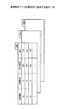
図16は機能制限管理部860に記憶されている機能制限リストを模式的に説明する図の一例である。機能制限リストでは、遠隔会議IDに各機能の制限の有無が対応づけられている。図16では遠隔会議IDは、遠隔会議を主催する主催装置のIPアドレスとしているが、遠隔会議IDは会議を一意に指定する識別子であればよく、数値、アルファベット、文字、又は、記号の任意の組み合わせでもよい。   FIG. 16 is an example of a diagram schematically illustrating a function restriction list stored in the function restriction management unit 860. In the function restriction list, the presence / absence of restriction of each function is associated with the remote conference ID. In FIG. 16, the remote conference ID is the IP address of the hosting device that hosts the remote conference. However, the remote conference ID may be an identifier that uniquely specifies the conference, and may be any numerical value, alphabet, character, or symbol. A combination may be used.

会議に参加しているクライアント機20が可能な機能は、USBメモリに保存、メール送信、ページ印刷、ファイル読み込み、ページ作成、画面キャプチャ、リカバリ、バックアップ、映像入力、ページ削除、ページ複製、ページ切り替え、ページ書き込み、などである。なお、機能を特定するために各機能には予め固有の識別子が与えられている。例えば、USBメモリに保存という機能の識別子は「SAVE01」の如くである。   Functions that can be performed by the client machine 20 participating in the conference are USB memory storage, mail transmission, page printing, file reading, page creation, screen capture, recovery, backup, video input, page deletion, page duplication, and page switching. , Page write, etc. In order to specify the function, each function is given a unique identifier in advance. For example, the identifier of the function of saving in the USB memory is “SAVE01”.

また、各機能が制限されている場合は「FALSE」と、制限されていない場合は「TRUE」と設定されている。例えば、遠隔会議ID=123.123.123.123の遠隔会議では、参加するクライアント機の機能制限はない。遠隔会議ID=123.123.123.124の遠隔会議では、一部の機能が制限されており、遠隔会議ID=123.123.123.125の遠隔会議では、すべての機能が制限されている。   Further, “FALSE” is set when each function is restricted, and “TRUE” is set when each function is not restricted. For example, in the remote conference with the remote conference ID = 123.123.123.123, there is no function restriction on the client machine to participate. In the remote conference with the remote conference ID = 123.123.123.124, some functions are limited, and in the remote conference with the remote conference ID = 123.123.123.125, all functions are limited.

(機能制限に関するUI画像)
図17〜19は、機能制限リストの作成画面の一例を示す図である。図17の画面は、主催装置のユーザが会議を開催する際に電子黒板2を操作することで、UI画像生成部33が作成する。図17では「以下の項目を選択することで、参加者の機能を制限できます。」というメッセージ201と共に、保存機能(特許請求の範囲の保存操作の一例である)、編集機能(特許請求の範囲の保存操作の一例である)、及び、表示機能(特許請求の範囲の表示操作の一例である)を選択するためのチェックボックス203が表示されている。チェックボックス203がチェックされた機能は制限される。保存機能では、ディスプレイ3に表示された画像(例えば、ページデータ、ファイルが開いて表示された画像)を保存可能なので、保存機能が制限されることでセキュリティを向上できる。
(UI image regarding function restriction)
17 to 19 are diagrams illustrating an example of a function restriction list creation screen. The UI image generation unit 33 creates the screen of FIG. 17 by operating the electronic blackboard 2 when the user of the hosting device holds a meeting. In FIG. 17, a message 201 “A function of a participant can be restricted by selecting the following items”, a save function (an example of a save operation of claims), an edit function (claim claims) And a check box 203 for selecting a display function (an example of a display operation of claims). Functions for which the check box 203 is checked are restricted. Since the image displayed on the display 3 (for example, page data, an image displayed by opening a file) can be stored in the storage function, security can be improved by limiting the storage function.

保存機能、編集機能、表示機能は、それぞれの機能をまとめたものであり、ユーザがチェックボックス203をチェックすることで保存機能、編集機能又は表示機能に分類される全ての機能を制限できる。また、ユーザが詳細ボタン202を押下することで、図18に示すように、保存機能に分類される詳細な機能が表示される。編集機能、表示機能についても同様にそれぞれの機能の詳細が表示される。   The storage function, the editing function, and the display function are a combination of the respective functions, and all functions classified into the storage function, the editing function, and the display function can be restricted by checking the check box 203 by the user. Further, when the user presses the detail button 202, as shown in FIG. 18, detailed functions classified into the storage function are displayed. The details of each function are also displayed for the editing function and the display function.

開催するボタン204は、会議を開催するためのボタンである。開催するボタン204が押下されると、制限受付部261が機能制限を受け付ける。これにより、クライアント機20の遠隔参加処理部62が開催要求と機能制限リストをサーバ機90の遠隔接続要求受信部71に送信する。なお、キャンセルボタン205は会議を開催することなく作成画面を終了するためのボタンである。   The hold button 204 is a button for holding a conference. When the holding button 204 is pressed, the restriction receiving unit 261 receives a function restriction. As a result, the remote participation processing unit 62 of the client machine 20 transmits the holding request and the function restriction list to the remote connection request receiving unit 71 of the server machine 90. A cancel button 205 is a button for ending the creation screen without holding a meeting.

図18は、編集機能の詳細ボタン202が押下された場合の機能制限リストの作成画面の一例を示す図である。個別の機能が表示されると、詳細ボタン202は戻るボタン207に変わり、戻るボタン207を押下することで個別の機能項目を非表示にできる。保存機能は、例えば、USBメモリに保存、メール送信、ページ印刷、バックアップ、リカバリである。それぞれにチェックボックス206が配置されているので、ユーザは任意の機能を選択して制限することができる。   FIG. 18 is a diagram illustrating an example of a function restriction list creation screen when the edit function detail button 202 is pressed. When an individual function is displayed, the detail button 202 changes to a return button 207, and the individual function item can be hidden by pressing the return button 207. The storage function is, for example, storage in a USB memory, mail transmission, page printing, backup, and recovery. Since a check box 206 is arranged for each, the user can select and restrict an arbitrary function.

なお、編集機能の詳細ボタン202を押下すると、編集機能に分類される具体的な編集のための機能として、チェックボックスと共に、ページ作成、画面キャプチャ、ページ削除、ページ複製、及び、ページ書き込みなどが表示される。ページ作成やページ書き込みが制限されることで、機密情報の書き込みを制限できるのでセキュリティを向上できる。画面キャプチャが制限されることで、PC6が表示している画面が保存できなくなるのでセキュリティを向上できる。ページ複製が制限されることでページデータの配布が困難になるのでセキュリティを向上できる。ページ削除が制限されることで、ページデータの紛失を防止できる。また、ページ作成やページ書き込みなどが制限されれば、主催装置のユーザが会議の進行を制御しやすくなる。   When the detailed button 202 of the edit function is pressed, a page creation, screen capture, page deletion, page duplication, page writing, and the like, together with check boxes, are provided as specific editing functions classified into the edit function. Is displayed. By restricting page creation and page writing, the writing of confidential information can be restricted, so that security can be improved. Since the screen capture is restricted, the screen displayed on the PC 6 cannot be saved, so that security can be improved. Restricting page duplication makes it difficult to distribute page data, thus improving security. By restricting page deletion, loss of page data can be prevented. Also, if page creation, page writing, etc. are restricted, it becomes easier for the user of the hosting device to control the progress of the conference.

また、表示機能の詳細ボタン202を押下すると、表示機能に分類される具体的な表示のための機能として、チェックボックスと共に、ファイル読み込み、ページ切り替え、及び、映像入力、などが表示される。参加装置からディスプレイ3に表示される内容を変更できなくなるので、主催装置のユーザが会議の進行を制御しやすくなる。また、ファイル読み込みが制限されることで、参加装置が保持する任意のファイルの内容の表示が困難になりセキュリティを向上できる。映像入力が制限されることで、参加装置が保持する映像の表示が困難になりセキュリティを向上できる。   When the detail button 202 of the display function is pressed, file reading, page switching, video input, and the like are displayed together with check boxes as specific display functions classified as display functions. Since the contents displayed on the display 3 from the participating device cannot be changed, the user of the sponsoring device can easily control the progress of the conference. Further, by restricting file reading, it becomes difficult to display the contents of any file held by the participating devices, and security can be improved. By restricting the video input, it becomes difficult to display the video held by the participating devices, and the security can be improved.

図19は、遠隔会議に参加する参加装置がディスプレイ3に表示する画面の一例を示す。図19では「以下の機能が制限されていますが、参加しますか?」というメッセージ210と共に、制限されている機能が表示されている。この画面は、サーバ機90に参加要請した参加装置が、サーバ機90から機能制限管理部860に記憶されている機能制限リストを受信して表示する。   FIG. 19 shows an example of a screen displayed on the display 3 by the participating devices participating in the remote conference. In FIG. 19, the restricted functions are displayed together with the message 210 “The following functions are restricted, but will you participate?”. In this screen, the participation apparatus that has requested participation in the server machine 90 receives the function restriction list stored in the function restriction management unit 860 from the server machine 90 and displays it.

参加装置のUI画像生成部33は機能制限リストを参照して図19の画面を表示する。図19においても保存機能、編集機能、表示機能は、それぞれの機能をまとめたものであり、ユーザが詳細ボタン202を押下することで、制限の詳細な内容を表示できる。ユーザは参加しようとする会議の制限を把握して、参加するか否かを判断できる。参加するボタン208を押下すると、主催装置のサーバ機90に参加要求が送信され、キャンセルボタン209を押下すると、図19の画面が終了する。   The UI image generation unit 33 of the participating device displays the screen in FIG. 19 with reference to the function restriction list. Also in FIG. 19, the save function, the edit function, and the display function are a collection of the respective functions, and when the user presses the detail button 202, the detailed contents of the restriction can be displayed. The user can grasp the restriction of the meeting to join and determine whether or not to join. When the join button 208 is pressed, a join request is transmitted to the server device 90 of the hosting device, and when the cancel button 209 is pressed, the screen of FIG. 19 ends.

<実施形態の処理又は動作>
続いて、図21〜図23を用いて、本実施形態の処理又は動作について説明する。なお、図21〜23は、各電子黒板の処理を示したシーケンス図である。
<Process or Operation of Embodiment>
Next, the processing or operation of this embodiment will be described with reference to FIGS. 21 to 23 are sequence diagrams illustrating processing of each electronic blackboard.

図21〜23に示す実施形態では、電子黒板2aが遠隔共有処理を主催する主催装置(サーバ機及びクライアント機)としての役割を果たしており、電子黒板2b,2cが遠隔共有処理に参加する参加装置(クライアント機)としての役割を果たす場合について説明する。また、ここでは、電子黒板2a,2b,2cには、それぞれディスプレイ3a,3b,3cが接続され、更に、それぞれノートPC6a,6b,6cが接続されている。また、電子黒板2a,2b,2cでは、それぞれ電子ペン4a,4b,4cが使用される。   In the embodiment shown in FIGS. 21 to 23, the electronic blackboard 2a serves as a hosting device (server machine and client machine) that hosts the remote sharing process, and the electronic blackboards 2b and 2c participate in the remote sharing process. The case where it plays a role as (client machine) will be described. Further, here, the displays 3a, 3b, 3c are connected to the electronic blackboards 2a, 2b, 2c, respectively, and further notebook PCs 6a, 6b, 6c are connected respectively. Moreover, in the electronic blackboards 2a, 2b, and 2c, electronic pens 4a, 4b, and 4c are used, respectively.

図21は、電子黒板2aが機能制限付きで遠隔会議を開催するシーケンス図の一例を示す。   FIG. 21 shows an example of a sequence diagram in which the electronic blackboard 2a holds a remote conference with function restrictions.

電子黒板2aのユーザはUI画像生成部33が作成した機能制限リストの作成画面を操作して開催するボタン204を押下する。これにより制限受付部261が機能制限リストを作成する。クライアント機20の画像処理部30は遠隔参加処理部62に機能制限リストを出力し、遠隔参加処理部62は遠隔会議の開催要求と機能制限リストをサーバ機に送信する(S1)。   The user of the electronic blackboard 2a operates the function restriction list creation screen created by the UI image generation unit 33 and presses the button 204 to be held. Thereby, the restriction receiving unit 261 creates a function restriction list. The image processing unit 30 of the client machine 20 outputs the function restriction list to the remote participation processing part 62, and the remote participation processing part 62 transmits a remote conference holding request and the function restriction list to the server machine (S1).

サーバ機90の遠隔接続要求受信部71は遠隔会議の開催要求と機能制限リストを受信して、遠隔接続処理部81に出力する。これにより、遠隔接続処理部81は遠隔会議の開始処理を行う(S2)。具体的には、遠隔会議IDを作成し、機能制限リストを遠隔会議IDに対応づけて機能制限管理部860に記憶する。   The remote connection request receiving unit 71 of the server machine 90 receives the remote conference holding request and the function restriction list, and outputs them to the remote connection processing unit 81. As a result, the remote connection processing unit 81 performs a remote conference start process (S2). Specifically, a remote conference ID is created, and the function restriction list is stored in the function restriction management unit 860 in association with the remote conference ID.

機能制限リストを記憶すると、遠隔接続処理部81は遠隔接続結果送信部72を介して、クライアント機20の遠隔開始処理部61に開催許可を送信する(S3)。   When the function restriction list is stored, the remote connection processing unit 81 transmits a holding permission to the remote start processing unit 61 of the client machine 20 via the remote connection result transmission unit 72 (S3).

(参加の処理)
次に、図22を用いて、電子黒板2b,2cが遠隔共有処理に参加するための処理について説明する。
(Participation process)
Next, a process for the electronic blackboards 2b and 2c to participate in the remote sharing process will be described with reference to FIG.

ユーザが電子黒板2aの電源スイッチをオンにすると、電子黒板2aのクライアント部20が起動する。そして、ユーザがタッチパネル等の入力装置によってサーバ部90を起動させる操作をすると、クライアント部20の遠隔開始処理部61から同じ電子黒板2aのサーバ部90における遠隔接続要求受信部71に、サーバ部90の処理を開始させる指示を出力する。これにより、電子黒板2aでは、クライアント部20だけでなくサーバ部90も各種処理を開始可能となる(ステップS21)。   When the user turns on the power switch of the electronic blackboard 2a, the client unit 20 of the electronic blackboard 2a is activated. When the user performs an operation to activate the server unit 90 using an input device such as a touch panel, the server unit 90 is transferred from the remote start processing unit 61 of the client unit 20 to the remote connection request receiving unit 71 in the server unit 90 of the same electronic blackboard 2a. An instruction to start the process is output. Thereby, in the electronic blackboard 2a, not only the client unit 20 but also the server unit 90 can start various processes (step S21).

次に、電子黒板2aのクライアント機20におけるUI画像生成部33が電子黒板2aとの接続を確立するための接続情報を生成し、映像重畳部28が、UI画像生成部33から表示重畳部36を介して得た接続情報をディスプレイ3aに表示させる(ステップS22)。この接続情報には、主催装置のIPアドレス、及び今回の遠隔共有処理のために生成されたパスコードが含まれている。この場合、パスコード管理部810に記憶されているパスコードは、図5に示されている遠隔接続処理部81によって読み出され、遠隔接続結果送信部72、遠隔開始処理部61の順に送信される。更に、パスコードは、遠隔開始処理部61を含む通信制御部60から、図3に示されている画像処理部30に送信され、最終的にUI画像生成部33に入力される。これにより、接続情報には、パスコードが含まれる。そして、接続情報は、電子黒板2aのユーザによって、電話や電子メールにより、電子黒板2b,2cのユーザに伝えられる。なお、接続先管理テーブル440があれば、接続情報には、主催装置のIPアドレスが含まれていなくても、参加装置は参加要求を行うことができる。   Next, the UI image generation unit 33 in the client machine 20 of the electronic blackboard 2a generates connection information for establishing a connection with the electronic blackboard 2a, and the video superimposition unit 28 receives the display superimposition unit 36 from the UI image generation unit 33. The connection information obtained through is displayed on the display 3a (step S22). This connection information includes the host device's IP address and the passcode generated for the current remote sharing process. In this case, the passcode stored in the passcode management unit 810 is read by the remote connection processing unit 81 shown in FIG. 5 and transmitted in the order of the remote connection result transmission unit 72 and the remote start processing unit 61. The Further, the passcode is transmitted from the communication control unit 60 including the remote start processing unit 61 to the image processing unit 30 illustrated in FIG. 3 and finally input to the UI image generation unit 33. Thereby, the connection information includes the passcode. Then, the connection information is transmitted to the users of the electronic blackboards 2b and 2c by telephone or electronic mail by the user of the electronic blackboard 2a. If there is the connection destination management table 440, even if the connection information does not include the IP address of the hosting device, the participating device can make a participation request.

次に、電子黒板2b,2cでは、各ユーザによるタッチパネル等の入力装置の操作によって接続情報の入力を受け付けると、各電子黒板2a,2bのクライアント機20における遠隔参加処理部62が、接続情報のIPアドレスに基づき、通信ネットワーク9を介して、電子黒板2aのサーバ機90における遠隔接続要求受信部71に対してパスコードを送信して参加要求を行う(ステップS23,S24)。これにより、通信制御部70の遠隔接続要求受信部71は、各電子黒板2b,2cから、参加要求(パスコードを含む)を受信し、このパスコードを遠隔接続処理部81に出力する。また、この時、電子黒板2b、2cは遠隔会議IDを電子黒板2aに送信する。   Next, in the electronic blackboards 2b and 2c, when input of connection information is received by the operation of an input device such as a touch panel by each user, the remote participation processing unit 62 in the client machine 20 of each electronic blackboard 2a and 2b Based on the IP address, a participation request is made by transmitting a pass code to the remote connection request receiving unit 71 in the server 90 of the electronic blackboard 2a via the communication network 9 (steps S23 and S24). As a result, the remote connection request receiving unit 71 of the communication control unit 70 receives a participation request (including a passcode) from each of the electronic blackboards 2b and 2c, and outputs this passcode to the remote connection processing unit 81. At this time, the electronic blackboards 2b and 2c transmit the remote conference ID to the electronic blackboard 2a.

次に、遠隔接続処理部81は、電子黒板2b,2cの各クライアント機20から受信したパスコードに対し、パスコード管理部810で管理されているパスコードを用いて認証する(ステップS25)。そして、遠隔接続結果送信部72が、各電子黒板2b,2cのクライアント機20に認証結果を通知する(SステップS26,S27)。ステップS25の認証により、正当な電子黒板であると判断されていた場合には、主催装置である電子黒板2aと、参加装置である電子黒板2b,2cとの遠隔共有処理の通信が確立され、各電子黒板2b,2cのクライアント機20における遠隔参加処理部62が、それぞれ他の電子黒板との間の遠隔共有処理の開始を可能にする(ステップS28,S29)。   Next, the remote connection processing unit 81 authenticates the passcode received from each client machine 20 of the electronic blackboards 2b and 2c using the passcode managed by the passcode management unit 810 (step S25). And the remote connection result transmission part 72 notifies an authentication result to the client machine 20 of each electronic blackboard 2b, 2c (S step S26, S27). If it is determined by the authentication in step S25 that the electronic blackboard is a legitimate electronic blackboard, communication of remote sharing processing is established between the electronic blackboard 2a that is the hosting device and the electronic blackboards 2b and 2c that are participating devices. The remote participation processing unit 62 in the client machine 20 of each electronic blackboard 2b, 2c enables the start of remote sharing processing with each other electronic blackboard (steps S28, S29).

電子黒板2aの遠隔接続処理部81は遠隔会議の参加処理を行う(S29−1)。具体的には、遠隔会議IDをキーにして機能制限管理部860を検索し、遠隔会議IDに対応づけられた機能制限リストを読み出す。   The remote connection processing unit 81 of the electronic blackboard 2a performs a remote conference participation process (S29-1). Specifically, the function restriction management unit 860 is searched using the remote conference ID as a key, and the function restriction list associated with the remote conference ID is read.

電子黒板2aの遠隔接続処理部81は電子黒板2b、2cに機能制限を要求する(S29−2、29−3)。具体的には、機能制限リストを送信して、電子黒板2b、2cのクライアント機20に表示させる。   The remote connection processing unit 81 of the electronic blackboard 2a requests the electronic blackboards 2b and 2c to restrict functions (S29-2 and 29-3). Specifically, the function restriction list is transmitted and displayed on the client device 20 of the electronic blackboards 2b and 2c.

電子黒板2b、2cのクライアント機20は機能制限処理を行う(S29−4、29−5)。機能制限処理では、図19に示すように、クライアント機20のUI画像生成部33が機能制限リストを用いて参加しようとする会議において制限されている機能を表示する。また、図19の画面で参加するボタン208が押下された場合、操作制限部331が機能制限に応じたUI画像を作成すること、である。機能制限されたUI画像については図24〜26で説明する。   The client machines 20 of the electronic blackboards 2b and 2c perform function restriction processing (S29-4 and 29-5). In the function restriction process, as shown in FIG. 19, the UI image generation unit 33 of the client machine 20 displays a function restricted in a meeting to join by using the function restriction list. Further, when the participation button 208 is pressed on the screen of FIG. 19, the operation restriction unit 331 creates a UI image according to the function restriction. The UI images whose functions are limited will be described with reference to FIGS.

電子黒板2b、2cのユーザが図19の画面で参加するボタン208を押下すると、電子黒板2b、2cの遠隔参加処理部62は機能制限受託を電子黒板2aに送信する(S29−6,29−7)。   When the user of the electronic blackboards 2b and 2c presses the join button 208 on the screen of FIG. 19, the remote participation processing unit 62 of the electronic blackboards 2b and 2c transmits a function restriction contract to the electronic blackboard 2a (S29-6, 29-). 7).

電子黒板2aの遠隔接続処理部81は参加登録処理を行う(S29−8)。すなわち、参加拠点管理テーブル820に参加装置のIPアドレスを登録する。   The remote connection processing unit 81 of the electronic blackboard 2a performs participation registration processing (S29-8). That is, the IP address of the participating device is registered in the participating base management table 820.

電子黒板2aの遠隔接続処理部81は、電子黒板2b、2cに参加許可を送信する(S29−9、29−10)。   The remote connection processing unit 81 of the electronic blackboard 2a transmits participation permission to the electronic blackboards 2b and 2c (S29-9, 29-10).

(出力画像の表示)
まず、電子黒板2bは、ディスプレイ3bに出力画像(C)を表示する(ステップS30)。具体的には、電子黒板2bの画像取得部31が、ノートPC6bから映像取得部21を介して、ノートPC6bで表示されている出力画像(C)のデータを受信し、表示重畳部36及び映像重畳部28を介してディスプレイ3bに送信することで、ディスプレイ3bは出力画像(C)を表示する。
次に、電子黒板2bの画像取得部31を含む画像処理部30が、遠隔画像送信部63に出力画像(C)のデータを送信することで、遠隔画像送信部63を含む通信制御部60が通信ネットワーク9を介して、主催装置である電子黒板2aの通信制御部70に出力画像(C)のデータを送信する(ステップS31)。これにより、電子黒板2aの遠隔画像受信部73は、出力画像(C)のデータを受信し、遠隔画像処理部82に出力することで、遠隔画像処理部82が画像データ記憶部830に出力画像(C)のデータを記憶する。
次に、主催装置である電子黒板2aは、ディスプレイ3aに出力画像(C)を表示する(ステップS32)。具体的には、電子黒板2aの遠隔画像処理部82は、遠隔画像受信部73から受信した出力画像(C)のデータを、遠隔画像送信部74に出力する。遠隔画像送信部74は、同じ主催装置である電子黒板2aのクライアント部20における遠隔画像受信部64に、出力画像(C)のデータを出力する。遠隔画像受信部64は、表示重畳部36に出力画像(C)のデータを出力する。表示重畳部36は、映像重畳部28に出力画像(C)のデータを出力する。映像重畳部28はディスプレイ3aに出力画像(C)のデータを出力する。これにより、ディスプレイ3aは、出力画像(C)を表示する。
次に、主催装置としての電子黒板2aのサーバ部90における遠隔画像送信部74を含む通信制御部70は、通信ネットワーク9を介して、出力画像(C)のデータの送信元である電子黒板2b以外の電子黒板2cの通信制御部60に出力画像(C)のデータを送信する(ステップS33)。これにより、参加装置である電子黒板2cの遠隔画像受信部64は、出力画像(C)のデータを受信する。
次に、電子黒板2cは、ディスプレイ3cに出力画像(C)を表示する(ステップS34)。具体的には、電子黒板2cの遠隔画像受信部64が、上記ステップS33によって受信された出力画像(C)のデータを、電子黒板2cの表示重畳部36に出力する。表示重畳部36は、映像重畳部28に出力画像(C)のデータを出力する。映像重畳部28はディスプレイ3cに出力画像(C)のデータを出力する。これにより、ディスプレイ3cは、出力画像(C)を表示する。
なお、出力画像(C)のデータだけでなく、UI画像(A)、及びストローク画像(B)の各データが、表示重畳部28に入力されている場合には、表示重畳部36により、重畳画像(A,B,C)が生成され、映像重畳部28はディスプレイ3cに重畳画像(A,B,C)のデータを出力する。また、テレビ会議端末7から映像重畳部28に、テレビ会議用の映像(E)のデータが送られて来ている場合には、映像重畳部28は、重畳画像(A,B,C)にピクチャーインピクチャーによりテレビ会議用の映像(E)のデータを重畳して、ディスプレイ3cに出力する。
(重畳画像の表示)
続いて、遠隔共有処理における操作データの処理について説明する。
(Output image display)
First, the electronic blackboard 2b displays the output image (C) on the display 3b (step S30). Specifically, the image acquisition unit 31 of the electronic blackboard 2b receives the data of the output image (C) displayed on the notebook PC 6b from the notebook PC 6b via the video acquisition unit 21, and displays the display superimposing unit 36 and the video. By transmitting to the display 3b via the superimposing unit 28, the display 3b displays the output image (C).
Next, the image processing unit 30 including the image acquisition unit 31 of the electronic blackboard 2 b transmits the output image (C) data to the remote image transmission unit 63, so that the communication control unit 60 including the remote image transmission unit 63 is performed. The data of the output image (C) is transmitted to the communication control unit 70 of the electronic blackboard 2a that is the hosting device via the communication network 9 (step S31). Thereby, the remote image receiving unit 73 of the electronic blackboard 2a receives the output image (C) data and outputs it to the remote image processing unit 82, so that the remote image processing unit 82 outputs the output image to the image data storage unit 830. The data of (C) is stored.
Next, the electronic blackboard 2a that is the hosting device displays the output image (C) on the display 3a (step S32). Specifically, the remote image processing unit 82 of the electronic blackboard 2 a outputs the output image (C) data received from the remote image receiving unit 73 to the remote image transmitting unit 74. The remote image transmitting unit 74 outputs the data of the output image (C) to the remote image receiving unit 64 in the client unit 20 of the electronic blackboard 2a which is the same host device. The remote image receiving unit 64 outputs the data of the output image (C) to the display superimposing unit 36. The display superimposing unit 36 outputs the output image (C) data to the video superimposing unit 28. The video superimposing unit 28 outputs the data of the output image (C) to the display 3a. Thereby, the display 3a displays the output image (C).
Next, the communication control unit 70 including the remote image transmission unit 74 in the server unit 90 of the electronic blackboard 2a as the hosting device via the communication network 9 is the electronic blackboard 2b that is the transmission source of the data of the output image (C). The data of the output image (C) is transmitted to the communication control unit 60 of the electronic blackboard 2c other than (step S33). Thereby, the remote image receiving part 64 of the electronic blackboard 2c which is a participating apparatus receives the data of an output image (C).
Next, the electronic blackboard 2c displays the output image (C) on the display 3c (step S34). Specifically, the remote image receiving unit 64 of the electronic blackboard 2c outputs the data of the output image (C) received in step S33 to the display superimposing unit 36 of the electronic blackboard 2c. The display superimposing unit 36 outputs the output image (C) data to the video superimposing unit 28. The video superimposing unit 28 outputs the data of the output image (C) to the display 3c. Thereby, the display 3c displays the output image (C).
When not only the output image (C) data but also the UI image (A) and stroke image (B) data are input to the display superimposing unit 28, the display superimposing unit 36 superimposes them. An image (A, B, C) is generated, and the video superimposing unit 28 outputs the data of the superimposed image (A, B, C) to the display 3c. When video conferencing video (E) data is sent from the video conference terminal 7 to the video superimposing unit 28, the video superimposing unit 28 converts the video superimposing image (A, B, C). The video (E) data for video conference is superimposed by picture-in-picture and output to the display 3c.
(Display of superimposed image)
Next, operation data processing in remote sharing processing will be described.

まず、電子黒板2bは、ユーザが電子ペン4bを用いて電子黒板2bにストローク画像(B)を描画している(ステップS41)。   First, in the electronic blackboard 2b, the user draws a stroke image (B) on the electronic blackboard 2b using the electronic pen 4b (step S41).

次に、電子黒板2bのクライアント機20における表示重畳部36は、図20に示されているように、UI画像(A)、出力画像(C)、及び背景画像(D)に対して、ストローク画像(B)を重畳し、映像重畳部28が、電子黒板2bのディスプレイ3b上に、重畳された重畳画像(A,B,C,D)を表示させる(ステップS42)。具体的には、電子黒板2bのストローク処理部32が座標検知部21及び接触検知部24からイベント振分部25を介して、操作データとしてのストローク画像(B)のデータを受信し、表示重畳部36に送信する。これにより、表示重畳部36は、UI画像(A)、及び出力画像(C)に対して、ストローク画像(B)を重畳することができ、映像重畳部28が電子黒板2bのディスプレイ3b上に重畳画像(A,B,C)を表示させることができる。   Next, as shown in FIG. 20, the display superimposing unit 36 in the client machine 20 of the electronic blackboard 2b performs strokes on the UI image (A), the output image (C), and the background image (D). The image (B) is superimposed, and the video superimposing unit 28 displays the superimposed superimposed images (A, B, C, D) on the display 3b of the electronic blackboard 2b (step S42). Specifically, the stroke processing unit 32 of the electronic blackboard 2b receives the stroke image (B) data as the operation data from the coordinate detection unit 21 and the contact detection unit 24 via the event distribution unit 25, and displays the superimposed image. It transmits to the part 36. Accordingly, the display superimposing unit 36 can superimpose the stroke image (B) on the UI image (A) and the output image (C), and the video superimposing unit 28 is placed on the display 3b of the electronic blackboard 2b. The superimposed image (A, B, C) can be displayed.

次に、電子黒板2bのストローク処理部32を含む画像処理部30が、遠隔操作送信部65にストローク画像(B)のデータを送信することで、電子黒板2bの遠隔操作送信部65は、通信ネットワーク2を介して、主催装置である電子黒板2aの通信制御部70にストローク画像(B)のデータを送信する(ステップS43)。これにより、電子黒板2aの遠隔操作受信部75は、ストローク画像(B)のデータを受信し、遠隔操作処理部83に出力することで、遠隔操作処理部83が操作合成処理部84にストローク画像(B)のデータを出力する。このようにして、電子黒板2bで描画されたストローク画像(B)のデータは、描画される度に、主催装置である電子黒板2aの遠隔操作処理部83に順次送信される。このストローク画像(B)のデータは、図7に示されているストロークデータID毎に示されるデータである。よって、例えば、上述したように、ユーザが電子ペン4によってアルファベット「T」を描く場合は二筆書きとなるため、2つのストロークデータIDのそれぞれで示されるストローク画像(B)のデータが順次送信される。   Next, the image processing unit 30 including the stroke processing unit 32 of the electronic blackboard 2b transmits the stroke image (B) data to the remote operation transmission unit 65, so that the remote operation transmission unit 65 of the electronic blackboard 2b communicates. The data of the stroke image (B) is transmitted via the network 2 to the communication control unit 70 of the electronic blackboard 2a that is the hosting device (step S43). Thereby, the remote operation receiving unit 75 of the electronic blackboard 2a receives the data of the stroke image (B) and outputs it to the remote operation processing unit 83, so that the remote operation processing unit 83 sends the stroke image to the operation composition processing unit 84. The data of (B) is output. In this way, the data of the stroke image (B) drawn on the electronic blackboard 2b is sequentially transmitted to the remote operation processing unit 83 of the electronic blackboard 2a that is the hosting device every time it is drawn. The data of the stroke image (B) is data shown for each stroke data ID shown in FIG. Therefore, for example, as described above, when the user draws the alphabet “T” with the electronic pen 4, the stroke image (B) indicated by each of the two stroke data IDs is sequentially transmitted. Is done.

次に、主催装置である電子黒板2aは、ディスプレイ3aに、電子黒板2bから送られて来たストローク画像(B)のデータが含まれた重畳画像(A,B,C)を表示する(ステップS44)。具体的には、電子黒板2aの操作合成処理部84は、遠隔操作処理部83を介して順次送られて来た複数のストローク画像(B)のデータを合成して、操作データ記憶部840に記憶するとともに遠隔操作処理部83に戻す。これにより、隔操作処理部83は、操作合成処理部84から受信した、合成後のストローク画像(B)のデータを、遠隔操作送信部76に出力する。遠隔操作送信部76は、同じ主催装置である電子黒板2aのクライアント部20における遠隔操作受信部66に、合成後のストローク画像(B)のデータを出力する。遠隔操作受信部66は、画像処理部30における表示重畳部36に、合成後のストローク画像(B)のデータを出力する。よって、表示重畳部36は、UI画像(A)、及び出力画像(C)に対して、合成後のストローク画像(B)を重畳する。最後に、映像重畳部28が、表示重畳部36によって重畳された重畳画像(A,B,C)をディスプレイ3a上に表示させる。
次に、主催装置としての電子黒板2aのサーバ部90における遠隔操作送信部76を含む通信制御部70は、通信ネットワーク9を介して、ストローク画像(B)のデータの送信元である電子黒板2b以外の電子黒板2cの通信制御部60に、合成後のストローク画像(B)のデータを送信する(ステップS45)。これにより、参加装置である電子黒板2cの遠隔操作受信部66は、合成後のストローク画像(B)のデータを受信する。
次に、電子黒板2cは、ディスプレイ3cに重畳画像(A,B,C)を表示する(ステップS34)。具体的には、電子黒板2cの遠隔操作受信部66が、上記ステップS45によって受信された合成後のストローク画像(B)のデータを、電子黒板2cの画像処理部30に出力する。画像処理部30の表示重畳部36は、UI画像(A)、及び出力画像(C)の各データと、合成後のストローク画像(B)のデータを重畳し、映像重畳部28に重畳画像(A,B,C)のデータを出力する。映像重畳部28は、ディスプレイ3cに重畳画像(A,B,C)のデータを出力する。これにより、ディスプレイ3cは、重畳画像(A,B,C)を表示する。
なお、上記処理では、ディスプレイ3上に出力画像(C)が表示されているが、この出力画像(C)に代えて、背景画像(D)を表示してもよい。また、出力画像(C)と背景画像(D)との排他的な関係をやめて、出力画像(C)と背景画像(D)との両方を同時にディスプレイ3上に表示させてもよい。
(参加の終了)
続いて、図23を用いて、参加装置が遠隔共有処理への参加を終了する処理について説明する。図23に示す実施形態では、電子黒板2cが参加を終了する処理が示されている。
Next, the electronic blackboard 2a, which is the hosting device, displays on the display 3a a superimposed image (A, B, C) including the data of the stroke image (B) sent from the electronic blackboard 2b (Step S). S44). Specifically, the operation composition processing unit 84 of the electronic blackboard 2a synthesizes the data of the plurality of stroke images (B) sequentially sent via the remote operation processing unit 83 and stores them in the operation data storage unit 840. Store and return to the remote operation processing unit 83. Thereby, the interval operation processing unit 83 outputs the data of the combined stroke image (B) received from the operation combining processing unit 84 to the remote operation transmitting unit 76. The remote operation transmitting unit 76 outputs the combined stroke image (B) data to the remote operation receiving unit 66 in the client unit 20 of the electronic blackboard 2a which is the same hosting device. The remote operation receiving unit 66 outputs the combined stroke image (B) data to the display superimposing unit 36 in the image processing unit 30. Therefore, the display superimposing unit 36 superimposes the combined stroke image (B) on the UI image (A) and the output image (C). Finally, the video superimposing unit 28 displays the superimposed image (A, B, C) superimposed by the display superimposing unit 36 on the display 3a.
Next, the communication control unit 70 including the remote operation transmission unit 76 in the server unit 90 of the electronic blackboard 2a as the hosting device via the communication network 9 is the electronic blackboard 2b that is the transmission source of the stroke image (B) data. The composite stroke image (B) data is transmitted to the communication control unit 60 of the electronic blackboard 2c other than (step S45). Thereby, the remote operation receiving part 66 of the electronic blackboard 2c which is a participating apparatus receives the data of the synthesized stroke image (B).
Next, the electronic blackboard 2c displays the superimposed image (A, B, C) on the display 3c (step S34). Specifically, the remote operation receiving unit 66 of the electronic blackboard 2c outputs the combined stroke image (B) data received in step S45 to the image processing unit 30 of the electronic blackboard 2c. The display superimposing unit 36 of the image processing unit 30 superimposes each data of the UI image (A) and the output image (C) and the data of the combined stroke image (B), and superimposes the superimposed image ( A, B, C) data is output. The video superimposing unit 28 outputs the data of the superimposed image (A, B, C) to the display 3c. Thereby, the display 3c displays a superimposed image (A, B, C).
In the above processing, the output image (C) is displayed on the display 3, but a background image (D) may be displayed instead of the output image (C). Alternatively, the exclusive relationship between the output image (C) and the background image (D) may be stopped, and both the output image (C) and the background image (D) may be displayed on the display 3 at the same time.
(End of participation)
Next, a process in which the participating device ends participation in the remote sharing process will be described with reference to FIG. In the embodiment shown in FIG. 23, a process is shown in which the electronic blackboard 2c finishes participation.

まず、電子黒板2cでは、ユーザによるタッチパネル等の入力装置の操作によって参加の終了要求を受け付けると、遠隔参加処理部62は、主催装置としての電子黒板2aのサーバ部90における通信制御部70に、参加の終了要求を行う(ステップS47)。これにより、通信制御部70の遠隔接続要求受信部71は、電子黒板2cから、参加の終了要求を受信し、遠隔接続処理部81に、電子黒板2cのIPアドレスとともに参加の終了要求を出力する。そして、電子黒板2aの遠隔接続処理部81は、遠隔接続要求受信部71から送られて来たIPアドレスに基づいて、参加拠点管理テーブル820から、参加の終了要求を行った電子黒板2cのIPアドレス及び電子黒板2cが設置されている拠点の名称を削除し、遠隔接続結果送信部72に、電子黒板2cのIPアドレス及び削除した旨の通知を出力する。
次に、遠隔接続結果送信部72を含んだ通信制御部70が、通信ネットワーク9を介して、電子黒板2cのクライアント部20における通信制御部60に、参加の終了を指示する(ステップS48)。これにより、電子黒板2cにおける通信制御部60の遠隔参加処理部62が、遠隔共有処理の通信を切断することで、参加の終了処理を行うことで、参加が終了する(ステップS49)。
First, in the electronic blackboard 2c, when an end request for participation is received by an operation of an input device such as a touch panel by the user, the remote participation processing unit 62 sends a communication control unit 70 in the server unit 90 of the electronic blackboard 2a as a host device to the communication control unit 70. A request to end participation is made (step S47). Thereby, the remote connection request receiving unit 71 of the communication control unit 70 receives the participation end request from the electronic blackboard 2c, and outputs the participation end request together with the IP address of the electronic blackboard 2c to the remote connection processing unit 81. . Then, the remote connection processing unit 81 of the electronic blackboard 2a, based on the IP address sent from the remote connection request receiving unit 71, from the participation base management table 820, the IP of the electronic blackboard 2c that has requested participation. The address and the name of the base where the electronic blackboard 2c is installed are deleted, and the remote connection result transmission unit 72 outputs the IP address of the electronic blackboard 2c and a notification of the deletion.
Next, the communication control unit 70 including the remote connection result transmission unit 72 instructs the communication control unit 60 in the client unit 20 of the electronic blackboard 2c to end participation via the communication network 9 (step S48). As a result, the remote participation processing unit 62 of the communication control unit 60 in the electronic blackboard 2c disconnects the communication of the remote sharing process, thereby completing the participation process, thereby completing the participation (step S49).

なお、図21〜23に示す実施形態では、クライアント機が画像フレームを提供するが、サーバ機が画像フレームを送信してもよい。また、本実施形態では、画像フレームを提供するクライアント機が描画情報を送信するが、他のクライアント機やサーバ機が描画情報を送信してもよい。さらに、本実施形態では、画像フレームを提供しないクライアント機が位置指示イベントを送信するが、画像フレームを提供しないサーバ機が位置指示イベント情報を送信してもよい。   21 to 23, the client machine provides an image frame, but the server machine may transmit the image frame. In this embodiment, a client machine that provides an image frame transmits drawing information. However, other client machines or server machines may transmit drawing information. Furthermore, in this embodiment, a client machine that does not provide an image frame transmits a position instruction event, but a server machine that does not provide an image frame may transmit position instruction event information.

(機能制限の例)
図24は、ディスプレイ3に表示されるUI画像の一例を示す。このUI画像では、ディスプレイ3の右側と下側にそれぞれアイコンが表示されている。これらのアイコンは、操作制限部331がUI画像において機能を選択不能にするので、参加装置のユーザの操作を確実に制限できる。これらのアイコンは、特許請求の範囲の表示部品の一例である。
(Example of function restriction)
FIG. 24 shows an example of a UI image displayed on the display 3. In this UI image, icons are displayed on the right side and the lower side of the display 3, respectively. These icons make it impossible for the operation restriction unit 331 to select a function in the UI image, so that the operation of the user of the participating device can be restricted with certainty. These icons are examples of display parts in claims.

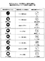
図25は、UI画像の右側の各アイコンをユーザが選択した場合の機能と、機能制限の対応について説明する図の一例である。ペンアイコンはユーザがホワイトボードに文字などを書き込むためのアイコンであり、ユーザはペンの色や太さを変更できる。機能制限リストの作成画面において「ページ書き込み」がチェックされると、ペンアイコンは選択不能となる。選択不能な表示方法は、例えば、白黒反転すること、アイコンそのものを非表示にすること、アイコンにバツ印を描画すること、などである。   FIG. 25 is an example of a diagram for explaining the correspondence between the function when the user selects each icon on the right side of the UI image and the function restriction. The pen icon is an icon for the user to write characters and the like on the whiteboard, and the user can change the color and thickness of the pen. When “Write Page” is checked on the function restriction list creation screen, the pen icon cannot be selected. Examples of display methods that cannot be selected include black-and-white reversal, non-display of the icon itself, and drawing a cross mark on the icon.

選択/削除アイコンはホワイトボードに書き込んだストロークを選択して拡大・縮小や移動、削除するためのアイコンである。機能制限リストの作成画面において「ページ書き込み」がチェックされると、選択/削除アイコンは選択不能となる。   The selection / deletion icon is an icon for selecting a stroke written on the whiteboard, enlarging / reducing, moving, or deleting. When “write page” is checked on the function restriction list creation screen, the selection / deletion icon cannot be selected.

キャプチャーアイコンは、ディスプレイに書き込んだ内容を、ユーザがキャプチャーしてページに記録するためのアイコンである。パソコンなど、接続した機器の映像を表示しているときは、表示している映像も一緒に記録される。機能制限リストの作成画面において「画面キャプチャ」がチェックされると、キャプチャーアイコンは選択不能となる。   The capture icon is an icon for the user to capture the content written on the display and record it on the page. When displaying the video of a connected device such as a personal computer, the displayed video is also recorded. When “Screen Capture” is checked on the function restriction list creation screen, the capture icon cannot be selected.

新規ページアイコンは、ユーザが新しいページを表示するためのアイコンである。機能制限リストの作成画面において「ページ作成」がチェックされると、新規ページアイコンは選択不能となる。   The new page icon is an icon for the user to display a new page. When “Create Page” is checked on the function restriction list creation screen, the new page icon cannot be selected.

ページ送りアイコンは、表示しているページの次のページを表示するためのアイコンである。機能制限リストの作成画面において「ページ切り替え」がチェックされると、ページ送りアイコンは選択不能となる。   The page feed icon is an icon for displaying the next page of the displayed page. When “page switching” is checked on the function restriction list creation screen, the page feed icon cannot be selected.

ページ戻しアイコンは、表示しているページの前のページを表示するためのアイコンである。機能制限リストの作成画面において「ページ切り替え」がチェックされると、ページ戻しアイコンは選択不能となる。   The page return icon is an icon for displaying the page before the displayed page. When “page switching” is checked on the function restriction list creation screen, the page return icon cannot be selected.

USBメモリーアイコンは、すべてのキャプチャーページをPDF ファイルにしてUSBメモリーに保存するためのアイコンである。機能制限リストの作成画面において「USBメモリに保存」がチェックされると、USBメモリーアイコンは選択不能となる。   The USB memory icon is an icon for saving all capture pages as PDF files and storing them in the USB memory. When “Save to USB memory” is checked on the function restriction list creation screen, the USB memory icon cannot be selected.

メール保存アイコンは、すべてのキャプチャーページをPDF ファイルにしてメールで送信するためのアイコンである。機能制限リストの作成画面において「メール送信」がチェックされると、メール保存アイコンは選択不能となる。   The email storage icon is an icon for sending all captured pages as PDF files by email. When “Mail transmission” is checked on the function restriction list creation screen, the mail storage icon cannot be selected.

図26は、下側の各アイコンをユーザが選択した場合の機能と、機能制限の対応について説明する図の一例である。   FIG. 26 is an example of a diagram for explaining the correspondence between the function when the user selects each lower icon and the function restriction.

ページアイコンは、記録されているページのサムネイルである。ユーザは任意のサムネイルを選択してスクリーンに表示することができる。機能制限リストの作成画面において「ページ切り替え」がチェックされると、ページアイコンは選択不能となる。   The page icon is a thumbnail of a recorded page. The user can select any thumbnail and display it on the screen. When “page switching” is checked on the function restriction list creation screen, the page icon cannot be selected.

ページ削除アイコンは、表示しているページを削除するためのアイコンである。機能制限リストの作成画面において「ページ削除」がチェックされると、ページ削除アイコンは選択不能となる。   The page deletion icon is an icon for deleting the displayed page. When “Delete page” is checked on the function restriction list creation screen, the page deletion icon cannot be selected.

スクリーンページアイコンは、コンピューター入力に接続した機器の映像を表示・切り替えるためのアイコンである。機能制限リストの作成画面において「映像入力」がチェックされると、スクリーンページアイコンは選択不能となる。   The screen page icon is an icon for displaying / switching the image of the device connected to the computer input. When “video input” is checked on the function restriction list creation screen, the screen page icon cannot be selected.

このように、操作制限部331がUI画像において機能を選択不能にするので、拠点のユーザの操作を確実に制限できる。   As described above, since the operation restriction unit 331 disables selection of functions in the UI image, the operation of the user at the base can be restricted with certainty.

なお、本発明はこうした実施例に限られるものではなく、機能制限管理部860はサーバ機でなくクライアント機に記憶されていてもよいし、ネットワーク上に記憶されていてもよい。また、本実施例では参加装置の機能制限について説明したが、主催装置について機能制限してもよい。また、機能制限の設定の受け付けを主催装置が行ったが、参加装置が機能制限の設定の受け付けを行ってもよい。   The present invention is not limited to such an embodiment, and the function restriction management unit 860 may be stored in the client machine instead of the server machine, or may be stored on the network. Further, in the present embodiment, the function restriction of the participation apparatus has been described, but the function restriction may be applied to the host apparatus. In addition, although the host device has accepted the function restriction setting, the participating device may accept the function restriction setting.

実施例1では、主催装置が複数の参加装置の機能を一律に制限したが、本実施例では、参加装置毎に個別に機能を制限する画像処理システム1について説明する。   In the first embodiment, the host device uniformly restricts the functions of a plurality of participating devices, but in this embodiment, an image processing system 1 that restricts the functions individually for each participating device will be described.

電子黒板2b、2cのユーザが電子黒板2aのユーザに音声などで制限の緩和を要求してもよいし、電子黒板2aのユーザが参加装置2b、2cを確認して自主的に例えば参加装置2bにだけ制限を強化したり緩和してもよい。   The user of the electronic blackboard 2b, 2c may request the user of the electronic blackboard 2a to relax the restriction by voice or the like, or the user of the electronic blackboard 2a confirms the participation devices 2b, 2c and voluntarily, for example, the participation device 2b. Limits may only be tightened or relaxed.

任意の参加装置の制限を制御したい電子黒板2aのユーザは、ディスプレイ3に機能制限リストの作成画面を表示する。   The user of the electronic blackboard 2 a who wants to control the restriction of any participating device displays a function restriction list creation screen on the display 3.

図27は、本実施例の機能制限リストの作成画面の一例を示す図である。図27では、図17に対し、「参加者の機能を個別に制限します」というメッセージ211と共にIPアドレスの選択欄213が表示されている。この選択欄213には、参加拠点管理テーブルに登録されているIPアドレスが全て登録されている。なお、IPアドレスでなく拠点名を表示してもよい。   FIG. 27 is a diagram illustrating an example of a function restriction list creation screen according to the present embodiment. In FIG. 27, an IP address selection field 213 is displayed together with a message 211 “participant's functions are individually restricted” with respect to FIG. In this selection field 213, all IP addresses registered in the participating base management table are registered. The base name may be displayed instead of the IP address.

電子黒板2aのユーザは、選択欄213から個別に制限を緩和したい又は制限を強化したい参加装置を選択し、図17と同様に機能制限リストを作成する。ユーザが個別に制限ボタン212を押下すると、電子黒板2aのクライアント機20は参加装置のIPアドレスと共に機能制限リストをサーバ機90に送信する。サーバ機90の遠隔接続処理部81は参加装置のIPアドレスに対応づけて機能制限リストを記録する。   The user of the electronic blackboard 2a selects a participating device whose restriction is to be relaxed or to be strengthened individually from the selection column 213, and creates a function restriction list as in FIG. When the user individually presses the restriction button 212, the client machine 20 of the electronic blackboard 2a transmits the function restriction list to the server machine 90 together with the IP address of the participating device. The remote connection processing unit 81 of the server machine 90 records a function restriction list in association with the IP address of the participating device.

図28は、本実施例の機能制限管理部の機能制限リストを模式的に説明する図の一例である。本実施例では、1つの遠隔会議IDに対し最大、参加装置の数だけ機能制限リストが記録されうる。図示するように、電子黒板2bでは全ての機能が制限されていないが、電子黒板2cではページ作成等が制限されている。このように、主催装置のユーザは参加装置毎に個別に機能制限リストを作成できる。   FIG. 28 is an example of a diagram schematically illustrating a function restriction list of a function restriction management unit according to the present embodiment. In this embodiment, as many function restriction lists as the number of participating devices can be recorded for one remote conference ID. As illustrated, not all functions are restricted on the electronic blackboard 2b, but page creation and the like are restricted on the electronic blackboard 2c. In this way, the user of the sponsoring device can create a function restriction list for each participating device.

サーバ機90の遠隔接続処理部81は、IPアドレスに対応付けられている機能制限リストを、IPアドレスにより特定される参加装置に送信する。これにより、参加装置2b、2cは再度、機能制限処理を行うので、操作制限部331は個別に制限された機能をユーザが選択可能なUI画像を作成してディスプレイ3に表示できる。   The remote connection processing unit 81 of the server machine 90 transmits the function restriction list associated with the IP address to the participating device specified by the IP address. Thereby, since the participating devices 2b and 2c perform the function restriction process again, the operation restriction unit 331 can create and display on the display 3 a UI image that allows the user to select individually restricted functions.

本実施例では、このように参加装置の機能の制限を個別に緩和又は強化することができる。   In this embodiment, the restriction on the function of the participating device can be individually relaxed or strengthened in this way.

実施例1,2では機能制限リストに基づき参加装置の機能を静的に制限したが、本実施例では制限された機能を一時的に緩和することができる画像処理システム1について説明する。   In the first and second embodiments, the functions of the participating devices are statically restricted based on the function restriction list. However, in this embodiment, an image processing system 1 that can temporarily relax the restricted functions will be described.

主催装置のユーザとしては、参加装置の機能を原則的に厳しく制限しておくことが安心だが、議論の内容によっては保存機能、編集機能、又は、表示機能などを制限しなくてよい場合がある。また、会議の終了後に主催装置が電子メールなどでページデータなどを送信することも可能だが、会議の終了後はページデータの選択が面倒であるし、時間を取られてしまう。このため、一部のページデータを会議中に配信しておきたい場合もあると考えられる。   As a user of the hosting device, it is safe to restrict the functions of participating devices strictly in principle, but depending on the content of the discussion, it may not be necessary to restrict the storage function, editing function, display function, etc. . It is also possible for the hosting device to send page data or the like by e-mail after the conference is over, but after the conference is over, selecting page data is cumbersome and takes time. For this reason, it is considered that some page data may be desired to be distributed during the conference.

そこで、本実施例の画像処理システム1は、主催装置のユーザが一時的に制限を緩和することを可能とする。   Therefore, the image processing system 1 according to the present embodiment enables the user of the hosting device to relax the restriction temporarily.

図29は、本実施例の機能制限リストの作成画面の一例を示す図である。参加装置の制限を一時的に緩和したい電子黒板2aのユーザは、ディスプレイ3に機能制限リストの作成画面を表示する。   FIG. 29 is a diagram illustrating an example of a function restriction list creation screen according to the present embodiment. The user of the electronic blackboard 2 a who wants to temporarily relax the restrictions on the participating devices displays a function restriction list creation screen on the display 3.

図29では、「一時的に制限を緩和します」というメッセージ216と共に、時間の選択欄215が表示されている。この選択欄215には、制限を緩和する時間が登録されている。ユーザは選択欄から制限を一時的に緩和したい時間を選択しておく。   In FIG. 29, a time selection field 215 is displayed together with a message 216 “Temporarily relax the restriction”. In this selection column 215, a time for relaxing the restriction is registered. The user selects a time for which the restriction is temporarily relaxed from the selection column.

また、電子黒板2aのユーザは、保存機能、編集機能又は表示機能からチェックボックス203のチェックを外して制限を緩和する。これにより、任意の機能の制限を選択的に緩和できる。なお、個別の機能のチェックボックス203のチェックを外すのでなく、全ての機能の制限を緩和してもよい。   The user of the electronic blackboard 2a relaxes the restriction by unchecking the check box 203 from the storage function, editing function, or display function. Thereby, the restriction | limiting of arbitrary functions can be selectively eased. Note that the restriction on all functions may be relaxed instead of unchecking the check boxes 203 for individual functions.

また、全ての参加装置の機能を一律に緩和するのでなく、参加装置を指定して一時的に制限を緩和してもよい。   Further, the functions of all the participating devices may not be alleviated uniformly, but the restriction may be temporarily relaxed by designating the participating devices.

ユーザが緩和するボタン214を押下すると、電子黒板2aのクライアント機20は機能制限リストをサーバ機90に送信する。サーバ機90の遠隔接続処理部81は緩和前の機能制限リスト(以下、オリジナルという)に対し、一時的に有効となる機能制限リストを記録する。   When the user presses the relax button 214, the client machine 20 of the electronic blackboard 2a transmits a function restriction list to the server machine 90. The remote connection processing unit 81 of the server machine 90 records a function restriction list that is temporarily effective with respect to a function restriction list before relaxation (hereinafter referred to as an original).

図30は、本実施例の機能制限管理部の機能制限リストを模式的に説明する図の一例である。本実施例では、オリジナルの遠隔会議IDに対し、一時的に有効な機能制限リストが記録されている。オリジナルの機能制限リストではページ作成等が制限されているが、一時的に有効な機能制限リストでは全ての機能が制限されていない(参加装置がすべての機能を使用できる)。   FIG. 30 is an example of a diagram schematically illustrating the function restriction list of the function restriction management unit according to the present embodiment. In the present embodiment, a temporarily effective function restriction list is recorded for the original remote conference ID. In the original function restriction list, page creation or the like is restricted, but not all functions are restricted in the temporarily valid function restriction list (participating devices can use all functions).

サーバ機90の遠隔接続処理部81は、各参加装置に一時的に有効な機能制限リストを送信する。これにより、参加装置2b、2cは再度、機能制限処理を行うので、操作制限部331は機能が制限されていないUI画像を作成してディスプレイ3に表示できる。   The remote connection processing unit 81 of the server machine 90 transmits a temporarily effective function restriction list to each participating device. Thereby, since the participating devices 2b and 2c perform the function restriction process again, the operation restriction unit 331 can create a UI image whose function is not restricted and display it on the display 3.

また、サーバ機90の遠隔接続処理部81は、所定時間(図の例では10分)が経過すると、各参加装置にオリジナルの機能制限リストを送信する。これにより、参加装置2b、2cは再度、機能制限処理を行い、操作制限部331は機能が制限されているUI画像を作成してディスプレイ3に表示できる。   Also, the remote connection processing unit 81 of the server machine 90 transmits the original function restriction list to each participating device when a predetermined time (10 minutes in the figure) elapses. Accordingly, the participating devices 2b and 2c perform the function restriction process again, and the operation restriction unit 331 can create a UI image with a restricted function and display it on the display 3.

本実施例では、このように参加装置の操作の制限を一時的に緩和することができる。   In the present embodiment, the restriction on the operation of the participating device can be temporarily relaxed in this way.

1 画像処理システム
2 電子黒板(画像処理装置の一例)
3 ディスプレイ(表示手段の一例)
4 電子ペン
5 USBメモリ
6 ノートPC(情報処理端末の一例)
7 テレビ会議端末
8 PC
9 通信ネットワーク
20 クライアント機
30 画像処理部
60、70 通信制御部
80 データ管理部
90 サーバ機
1 Image processing system 2 Electronic blackboard (an example of an image processing device)
3 Display (an example of display means)
4 Electronic pen 5 USB memory 6 Notebook PC (an example of information processing terminal)
7 Video conference terminal 8 PC
DESCRIPTION OF SYMBOLS 9 Communication network 20 Client machine 30 Image processing part 60, 70 Communication control part 80 Data management part 90 Server machine

特許第5081088号公報Japanese Patent No. 5081088

Claims (6)

ネットワークを介して接続された複数の情報処理装置が通信するシステムであって、
情報処理装置は、他の情報処理装置が操作を受け付けることを制限する操作制限の設定を受け付ける制限受け付け手段と、
前記他の情報処理装置に前記操作制限の設定に基づく情報を送信する送信手段と、を有し、
前記制限受け付け手段は、前記他の情報処理装置に接続された表示手段に表示された画像を保存する保存操作、前記表示手段に表示された画像を編集する編集操作、又は、前記他の情報処理装置に画像を表示する表示操作、の制限を受け付けることで、
前記保存操作に分類される複数の操作、前記編集操作に分類される複数の操作、又は、前記表示操作に分類される複数の操作、の制限をまとめて受け付けるものであり、
前記他の情報処理装置は、
前記操作制限の設定に基づく情報によって、前記他の情報処理装置の操作受け付け手段による操作の受け付けを制限させる、ことを特徴とするシステム。
A system in which a plurality of information processing devices connected via a network communicate with each other,
The information processing apparatus includes a limit accepting unit that accepts an operation restriction setting that restricts another information processing apparatus from accepting an operation;
Transmission means for transmitting information based on the setting of the operation restriction to the other information processing apparatus,
The restriction accepting unit is a saving operation for saving an image displayed on a display unit connected to the other information processing apparatus, an editing operation for editing an image displayed on the display unit, or the other information processing. By accepting restrictions on display operations that display images on the device,
A plurality of operations classified as the saving operation, a plurality of operations classified as the editing operation, or a plurality of operations classified as the display operation are collectively accepted,
The other information processing apparatus
A system that restricts the acceptance of an operation by an operation accepting unit of the other information processing apparatus based on information based on the setting of the operation restriction.
前記制限受け付け手段は、前記保存操作に分類される複数の操作の1つ以上、前記編集操作に分類される複数の操作の1つ以上、及び、前記表示操作に分類される複数の操作の1つ以上、の制限を個別に受け付ける、
ことを特徴とする請求項1に記載のシステム。
The restriction accepting means is one or more of a plurality of operations classified as the saving operation, one or more of a plurality of operations classified as the editing operation, and one of a plurality of operations classified as the display operation. Accept one or more restrictions individually,
The system according to claim 1 .
前記操作受け付け手段は、前記表示手段に表示された表示部品がポインティングデバイスにより選択された場合に前記表示部品に対応する操作を受け付け、
前記他の情報処理装置は、前記操作制限に基づく情報により制限された操作に対応する前記表示部品をポインティングデバイスにより選択不能に表示するか又は表示しない、
ことを特徴とする請求項1又は2に記載のシステム。
The operation accepting unit accepts an operation corresponding to the display component when the display component displayed on the display unit is selected by a pointing device,
The other information processing apparatus displays or does not display the display component corresponding to the operation restricted by the information based on the operation restriction by the pointing device,
The system according to claim 1 or 2, characterized by the above.
前記制限受け付け手段は、他の情報処理装置の指定と共に、操作制限の設定を受け付け、
前記送信手段は、指定された前記他の情報処理装置ごとに前記操作制限に基づく情報を送信する、ことを特徴とする請求項1〜3のいずれか1項に記載のシステム。
The restriction accepting unit accepts setting of an operation restriction together with designation of another information processing apparatus,
The transmission unit, the system according to claim 1 for transmitting information based on the handling restriction for each of the other information processing apparatus is specified, it is characterized.
前記制限受け付け手段は、時間の指定を受け付け、前記時間に限り前記操作制限に基づく情報で制限されている操作の制限を許可する、
ことを特徴とする請求項1〜4のいずれか1項に記載のシステム。
The restriction accepting unit accepts designation of time, and permits the restriction of the operation restricted by the information based on the operation restriction only for the time.
The system according to any one of claims 1 to 4 .
ネットワークを介して接続された他の情報処理装置と通信する情報処理装置であって、
少なくとも他の情報処理装置が操作を受け付けることを制限する操作制限の設定を受け付ける制限受け付け手段と、
前記操作制限に基づく情報を前記他の情報処理装置に送信し、前記他の情報処理装置の操作受け付け手段による操作の受け付けを制限させる制限手段と、を有し、
前記制限受け付け手段は、前記他の情報処理装置に接続された表示手段に表示された画像を保存する保存操作、前記表示手段に表示された画像を編集する編集操作、又は、前記他の情報処理装置に画像を表示する表示操作、の制限を受け付けることで、
前記保存操作に分類される複数の操作、前記編集操作に分類される複数の操作、又は、前記表示操作に分類される複数の操作、の制限をまとめて受け付ける情報処理装置。
An information processing apparatus that communicates with another information processing apparatus connected via a network,
Restriction accepting means for accepting an operation restriction setting for restricting at least other information processing apparatuses to accept an operation;
Limiting means for transmitting information based on the operation restriction to the other information processing apparatus and restricting the acceptance of the operation by the operation accepting means of the other information processing apparatus,
The restriction accepting unit is a saving operation for saving an image displayed on a display unit connected to the other information processing apparatus, an editing operation for editing an image displayed on the display unit, or the other information processing. By accepting restrictions on display operations that display images on the device,
An information processing apparatus that collectively accepts restrictions on a plurality of operations classified as the saving operation, a plurality of operations classified as the editing operation, or a plurality of operations classified as the display operation .
JP2013192240A 2013-09-17 2013-09-17 System, information processing device Active JP6036621B2 (en)

Priority Applications (1)

Application Number Priority Date Filing Date Title
JP2013192240A JP6036621B2 (en) 2013-09-17 2013-09-17 System, information processing device

Applications Claiming Priority (1)

Application Number Priority Date Filing Date Title
JP2013192240A JP6036621B2 (en) 2013-09-17 2013-09-17 System, information processing device

Publications (3)

Publication Number Publication Date
JP2015060305A JP2015060305A (en) 2015-03-30
JP2015060305A5 JP2015060305A5 (en) 2016-05-12
JP6036621B2 true JP6036621B2 (en) 2016-11-30

Family

ID=52817805

Family Applications (1)

Application Number Title Priority Date Filing Date
JP2013192240A Active JP6036621B2 (en) 2013-09-17 2013-09-17 System, information processing device

Country Status (1)

Country Link
JP (1) JP6036621B2 (en)

Families Citing this family (3)

* Cited by examiner, † Cited by third party
Publication number Priority date Publication date Assignee Title
JP2016208394A (en) 2015-04-27 2016-12-08 株式会社リコー Information processing apparatus and image display method
JP7006330B2 (en) * 2018-02-05 2022-01-24 株式会社リコー Information processing equipment, image sharing system, image sharing method and program
JP7428027B2 (en) 2020-03-13 2024-02-06 株式会社リコー Communication systems, communication terminals, display methods, programs

Family Cites Families (5)

* Cited by examiner, † Cited by third party
Publication number Priority date Publication date Assignee Title
JP4892653B2 (en) * 2005-05-18 2012-03-07 株式会社アドイン研究所 Terminal device, server system, control method and control program thereof, and information sharing system
JP5211430B2 (en) * 2006-03-02 2013-06-12 富士ゼロックス株式会社 Electronic conference system, electronic conference support program, electronic conference support method, electronic conference control device, conference server computer
JP2010067064A (en) * 2008-09-11 2010-03-25 Konica Minolta Business Technologies Inc Information processor
JP5195564B2 (en) * 2009-03-23 2013-05-08 コニカミノルタホールディングス株式会社 Information processing system, information processing method, and information processing apparatus
JP2011070289A (en) * 2009-09-24 2011-04-07 Hitachi Solutions Ltd System for temporary change of authority setting

Also Published As

Publication number Publication date
JP2015060305A (en) 2015-03-30

Similar Documents

Publication Publication Date Title
JP6724358B2 (en) Electronic blackboard, program, data display method, image processing system
JP6094550B2 (en) Information processing apparatus and program
JP2015069284A (en) Image processing apparatus
JP6620494B2 (en) Communication system, information processing apparatus, communication method, program
JP6583432B2 (en) Image processing apparatus, image display method, and program
JP2016134014A (en) Electronic information board device, information processing method and program
JP6459545B2 (en) Image processing apparatus, image processing system, and image processing method
JP6402826B2 (en) Information processing apparatus, image display method, and program
JP6493546B2 (en) Electronic blackboard, storage medium, and information display method
JP6885416B2 (en) Electronic blackboards, image processing methods for electronic blackboards, and programs
JP2016139322A (en) Image processor and electronic blackboard provided with the same
JP6143100B2 (en) Image processing apparatus and image processing system
JP5846270B2 (en) Image processing system and information processing apparatus
JP2015056030A (en) Image processing apparatus and image processing system
JP2017076207A (en) Image processing device and image processing system
JP6036621B2 (en) System, information processing device
JP6631643B2 (en) Image processing apparatus, image processing system, and image processing method
JP2017091559A (en) Apparatus and method
JP7298224B2 (en) Display device and display method
JP7363064B2 (en) Image processing device, method, and program
JP2018067018A (en) Electronic blackboard, image processing method, image processing program, and image processing system
JP7388159B2 (en) Display device, display method
JP2017129890A (en) Coordinate detection apparatus, image processing apparatus, coordinate detection method, and program
JP2015056038A (en) Image processor and program

Legal Events

Date Code Title Description
A521 Written amendment

Free format text: JAPANESE INTERMEDIATE CODE: A523

Effective date: 20160317

A621 Written request for application examination

Free format text: JAPANESE INTERMEDIATE CODE: A621

Effective date: 20160317

A871 Explanation of circumstances concerning accelerated examination

Free format text: JAPANESE INTERMEDIATE CODE: A871

Effective date: 20160317

A975 Report on accelerated examination

Free format text: JAPANESE INTERMEDIATE CODE: A971005

Effective date: 20160330

A131 Notification of reasons for refusal

Free format text: JAPANESE INTERMEDIATE CODE: A131

Effective date: 20160621

A521 Written amendment

Free format text: JAPANESE INTERMEDIATE CODE: A523

Effective date: 20160819

TRDD Decision of grant or rejection written
A01 Written decision to grant a patent or to grant a registration (utility model)

Free format text: JAPANESE INTERMEDIATE CODE: A01

Effective date: 20161004

A61 First payment of annual fees (during grant procedure)

Free format text: JAPANESE INTERMEDIATE CODE: A61

Effective date: 20161017

R151 Written notification of patent or utility model registration

Ref document number: 6036621

Country of ref document: JP

Free format text: JAPANESE INTERMEDIATE CODE: R151