JP6035553B2 - Method and related apparatus and system for removing contaminants from hydrocarbon streams by swing adsorption - Google Patents
Method and related apparatus and system for removing contaminants from hydrocarbon streams by swing adsorption Download PDFInfo
- Publication number
- JP6035553B2 JP6035553B2 JP2013556781A JP2013556781A JP6035553B2 JP 6035553 B2 JP6035553 B2 JP 6035553B2 JP 2013556781 A JP2013556781 A JP 2013556781A JP 2013556781 A JP2013556781 A JP 2013556781A JP 6035553 B2 JP6035553 B2 JP 6035553B2
- Authority
- JP
- Japan
- Prior art keywords
- adsorbent
- pressure
- adsorbent bed
- swing adsorption
- stream
- Prior art date
- Legal status (The legal status is an assumption and is not a legal conclusion. Google has not performed a legal analysis and makes no representation as to the accuracy of the status listed.)
- Expired - Fee Related
Links
Images


Classifications
-
- B—PERFORMING OPERATIONS; TRANSPORTING
- B01—PHYSICAL OR CHEMICAL PROCESSES OR APPARATUS IN GENERAL
- B01D—SEPARATION
- B01D53/00—Separation of gases or vapours; Recovering vapours of volatile solvents from gases; Chemical or biological purification of waste gases, e.g. engine exhaust gases, smoke, fumes, flue gases, aerosols
- B01D53/02—Separation of gases or vapours; Recovering vapours of volatile solvents from gases; Chemical or biological purification of waste gases, e.g. engine exhaust gases, smoke, fumes, flue gases, aerosols by adsorption, e.g. preparative gas chromatography
- B01D53/04—Separation of gases or vapours; Recovering vapours of volatile solvents from gases; Chemical or biological purification of waste gases, e.g. engine exhaust gases, smoke, fumes, flue gases, aerosols by adsorption, e.g. preparative gas chromatography with stationary adsorbents
- B01D53/047—Pressure swing adsorption
- B01D53/0473—Rapid pressure swing adsorption
-
- C—CHEMISTRY; METALLURGY
- C10—PETROLEUM, GAS OR COKE INDUSTRIES; TECHNICAL GASES CONTAINING CARBON MONOXIDE; FUELS; LUBRICANTS; PEAT
- C10L—FUELS NOT OTHERWISE PROVIDED FOR; NATURAL GAS; SYNTHETIC NATURAL GAS OBTAINED BY PROCESSES NOT COVERED BY SUBCLASSES C10G, C10K; LIQUEFIED PETROLEUM GAS; ADDING MATERIALS TO FUELS OR FIRES TO REDUCE SMOKE OR UNDESIRABLE DEPOSITS OR TO FACILITATE SOOT REMOVAL; FIRELIGHTERS
- C10L3/00—Gaseous fuels; Natural gas; Synthetic natural gas obtained by processes not covered by subclass C10G, C10K; Liquefied petroleum gas
- C10L3/06—Natural gas; Synthetic natural gas obtained by processes not covered by C10G, C10K3/02 or C10K3/04
- C10L3/10—Working-up natural gas or synthetic natural gas
- C10L3/101—Removal of contaminants
- C10L3/102—Removal of contaminants of acid contaminants
- C10L3/104—Carbon dioxide
-
- B—PERFORMING OPERATIONS; TRANSPORTING
- B01—PHYSICAL OR CHEMICAL PROCESSES OR APPARATUS IN GENERAL
- B01D—SEPARATION
- B01D2256/00—Main component in the product gas stream after treatment
- B01D2256/24—Hydrocarbons
- B01D2256/245—Methane
-
- B—PERFORMING OPERATIONS; TRANSPORTING
- B01—PHYSICAL OR CHEMICAL PROCESSES OR APPARATUS IN GENERAL
- B01D—SEPARATION
- B01D2257/00—Components to be removed
- B01D2257/30—Sulfur compounds
- B01D2257/304—Hydrogen sulfide
-
- B—PERFORMING OPERATIONS; TRANSPORTING
- B01—PHYSICAL OR CHEMICAL PROCESSES OR APPARATUS IN GENERAL
- B01D—SEPARATION
- B01D2257/00—Components to be removed
- B01D2257/50—Carbon oxides
- B01D2257/502—Carbon monoxide
-
- B—PERFORMING OPERATIONS; TRANSPORTING
- B01—PHYSICAL OR CHEMICAL PROCESSES OR APPARATUS IN GENERAL
- B01D—SEPARATION
- B01D2259/00—Type of treatment
- B01D2259/40—Further details for adsorption processes and devices
- B01D2259/40011—Methods relating to the process cycle in pressure or temperature swing adsorption
- B01D2259/40035—Equalization
- B01D2259/40041—Equalization with more than three sub-steps
-
- B—PERFORMING OPERATIONS; TRANSPORTING
- B01—PHYSICAL OR CHEMICAL PROCESSES OR APPARATUS IN GENERAL
- B01D—SEPARATION
- B01D2259/00—Type of treatment
- B01D2259/40—Further details for adsorption processes and devices
- B01D2259/40011—Methods relating to the process cycle in pressure or temperature swing adsorption
- B01D2259/40043—Purging
- B01D2259/40049—Purging with more than three sub-steps
-
- B—PERFORMING OPERATIONS; TRANSPORTING
- B01—PHYSICAL OR CHEMICAL PROCESSES OR APPARATUS IN GENERAL
- B01D—SEPARATION
- B01D2259/00—Type of treatment
- B01D2259/40—Further details for adsorption processes and devices
- B01D2259/406—Further details for adsorption processes and devices using more than four beds
- B01D2259/4063—Further details for adsorption processes and devices using more than four beds using seven beds
-
- B—PERFORMING OPERATIONS; TRANSPORTING
- B01—PHYSICAL OR CHEMICAL PROCESSES OR APPARATUS IN GENERAL
- B01D—SEPARATION
- B01D53/00—Separation of gases or vapours; Recovering vapours of volatile solvents from gases; Chemical or biological purification of waste gases, e.g. engine exhaust gases, smoke, fumes, flue gases, aerosols
- B01D53/02—Separation of gases or vapours; Recovering vapours of volatile solvents from gases; Chemical or biological purification of waste gases, e.g. engine exhaust gases, smoke, fumes, flue gases, aerosols by adsorption, e.g. preparative gas chromatography
-
- Y—GENERAL TAGGING OF NEW TECHNOLOGICAL DEVELOPMENTS; GENERAL TAGGING OF CROSS-SECTIONAL TECHNOLOGIES SPANNING OVER SEVERAL SECTIONS OF THE IPC; TECHNICAL SUBJECTS COVERED BY FORMER USPC CROSS-REFERENCE ART COLLECTIONS [XRACs] AND DIGESTS
- Y02—TECHNOLOGIES OR APPLICATIONS FOR MITIGATION OR ADAPTATION AGAINST CLIMATE CHANGE
- Y02C—CAPTURE, STORAGE, SEQUESTRATION OR DISPOSAL OF GREENHOUSE GASES [GHG]
- Y02C20/00—Capture or disposal of greenhouse gases
- Y02C20/40—Capture or disposal of greenhouse gases of CO2
Description
本発明は、選択的な特徴、例えばシステム構成(コンフィグレーション)、吸着性構造及び吸着性材料及び/又はサイクルステップの組み合わせにより炭化水素流から汚染物質、例えばCO2及びH2Oを除去するスイング吸着方法に関する。 The present invention provides a swing that removes contaminants such as CO 2 and H 2 O from a hydrocarbon stream by a combination of selective features such as system configuration, adsorbent structure and adsorbent material and / or cycle steps. It relates to an adsorption method.
〔関連技術の説明〕
本願は、2011年3月1日に出願された米国特許出願第61/448,121号(発明の名称:METHODS OF REMOVING CONTAMINANTS FROM A HYDROCARBON STREAM BY SWING ADSORPTION AND RELATED APPARATUS AND SYSTEMS)の権益主張出願であり、この米国特許出願を参照により引用し、その記載内容全体を本明細書の一部とする。
[Description of related technology]
This application is an application for claiming the interest of US Patent Application No. 61 / 448,121 filed on March 1, 2011 (name of invention: METHODS OF REMOVING CONTAMINANTS FROM A HYDROCARBON STREAM BY SWING ADSORPTION AND RELATED APPARATUS AND SYSTEMS). This US patent application is hereby incorporated by reference, the entire contents of which are hereby incorporated by reference.
本願は、2011年3月1日に出願された米国特許出願第61/448,117号(発明の名称:APPARATUS AND SYSTEMS HAVING AN ENCASED ADSORBENT CONTACTOR AND SWING ADSORPTION PROCESSES RELATED THERETO)、2011年3月1日に出願された米国特許出願第61/448,120号(発明の名称:APPARATUS AND SYSTEMS HAVING A RECIPROCATING VALVE HEAD ASSEMBLY AND SWING ADSORPTION PROCESSES RELATED THERETO)、2011年3月1日に出願された米国特許出願第61/448,123号(発明の名称:APPARATUS AND SYSTEMS HAVING A ROTARY VALVE ASSEMBLY AND SWING ADSORPTION PROCESSES RELATED THERETO)、2011年3月1日に出願された米国特許出願第61/448,125号(発明の名称:APPARATUS AND SYSTEMS HAVING COMPACT CONFIGURATION MULTIPLE SWING ADSORPTION BEDS AND METHODS RELATED THERETO)及び2012年2月3日に出願された米国特許出願第61/594,824号(発明の名称:METHODS OF REMOVING CONTAMINANTS APAPRATUS AND SYSTEMS)に関し、これら米国特許出願の各々を参照により引用し、その記載内容を本明細書の一部とする。 This application is US Patent Application No. 61 / 448,117 filed on March 1, 2011 (invention name: APPARATUS AND SYSTEMS HAVING AN ENCASED ADSORBENT CONTACTOR AND SWING ADSORPTION PROCESSES RELATED THERETO), March 1, 2011. US Patent Application No. 61 / 448,120 (invention name: APPARATUS AND SYSTEMS HAVING A RECIPROCATING VALVE HEAD ASSEMBLY AND SWING ADSORPTION PROCESSES RELATED THERETO), filed on March 1, 2011 61 / 448,123 (Title of Invention: APPARATUS AND SYSTEMS HAVING A ROTARY VALVE ASSEMBLY AND SWING ADSORPTION PROCESSES RELATED THERETO), US Patent Application No. 61 / 448,125 filed on March 1, 2011 (Name: APPARATUS AND SYSTEMS HAVING COMPACT CONFIGURATION MULTIPLE SWING ADSORPTION BEDS AND METHODS RELATED THERETO) and US patents filed on February 3, 2012 Application No. 61 / 594,824 No. (entitled: METHODS OF REMOVING CONTAMINANTS APAPRATUS AND SYSTEMS) relates, and incorporated by reference each of these U.S. patent applications, incorporated herein its description.
ガス分離は、多くの業界で重要であり、このようなガス分離は、ガスの混合物を吸着性材料上に導くことによって達成でき、このような吸着性材料は、混合物の容易に吸着される度合いが低い成分に対して容易に吸着される度合いが高い成分を優先的に吸着する。多くの重要な形式のガス分離技術の1つは、スイング吸着、例えば圧力スイング吸着(PSA)である。PSA法は、圧力下において、ガスが微孔質吸着性材料の細孔構造内又はポリマー材料の自由体積内に吸着される傾向があるという事実を利用している。圧力が高ければ高いほど、吸着される標的ガス成分の量がそれだけ一層多くなる。圧力を減少させると、吸着状態の標的成分が放出され又は脱着される。PSA法を用いると、ガス混合物中のガスを分離することができる。と言うのは、互いに異なるガスは、吸着剤のミクロ(微)細孔又は自由体積を互いに異なる程度に満たす傾向があるからである。ガス混合物、例えば天然ガスを圧力下で例えばメタンよりも二酸化炭素に対してより選択性を示すポリマー又は微孔質吸着剤を収容した容器中に通した場合、二酸化炭素の少なくとも何分の一かが吸着剤によって選択的に吸着され、容器を出るガスは、メタンが富化される。吸着剤床が二酸化炭素を吸着するのにその能力の終わりに達すると、吸着剤床は、圧力を減少させることによって再生され、それにより吸着状態の二酸化炭素が放出される。吸着剤床は、次に、代表的にはパージされて再加圧され、すると新たな吸着サイクルのための準備ができている。 Gas separation is important in many industries, and such gas separation can be achieved by directing a mixture of gases onto the adsorbent material, and such adsorbent material is the degree to which the mixture is easily adsorbed. Preferentially adsorbs a component that is easily adsorbed to a low component. One of the many important types of gas separation techniques is swing adsorption, such as pressure swing adsorption (PSA). The PSA method takes advantage of the fact that under pressure, gas tends to be adsorbed within the pore structure of the microporous adsorbent material or within the free volume of the polymer material. The higher the pressure, the greater the amount of target gas component that is adsorbed. When the pressure is reduced, the adsorbed target component is released or desorbed. When the PSA method is used, the gas in the gas mixture can be separated. This is because different gases tend to fill the micro-pores or free volumes of the adsorbent to different degrees. When a gas mixture, such as natural gas, is passed under pressure into a container containing a polymer or microporous adsorbent that is more selective for carbon dioxide than methane, for example, at least a fraction of carbon dioxide Is selectively adsorbed by the adsorbent and the gas exiting the vessel is enriched with methane. When the adsorbent bed reaches its end of capacity to adsorb carbon dioxide, the adsorbent bed is regenerated by reducing the pressure, thereby releasing adsorbed carbon dioxide. The adsorbent bed is then typically purged and repressurized and is then ready for a new adsorption cycle.
当該技術分野においては新吸着性材料、新規且つ改良型平行チャネル接触器及び改良型迅速サイクルPSA(RC‐PSA)機器に関する種々の教示が存在するが、今日に至るまで、これらのうちで、供給ガスが高い圧力状態にあるときにメタンの良好な回収を行うという課題に対して実行可能な解決手段を提供しているものはない。これは、天然ガスが高い圧力(30〜700バール)で産出される場合が多く、市場への輸送前に追加の圧縮を回避するよう分離システムを高圧で作動させることが望ましいので、重要な課題である。PSA法を高圧に、特に多量のCO2を含む流れに関して高い圧力に拡張する際の一問題は、吸着ステップの終わりに、フローチャネル及びボイド空間内に相当な量の製品ガスが存在する場合があるということにある。これにより、所望の製品の回収が劣ると共に低純度製品流が生じる場合がある。 There are various teachings in the art relating to new adsorbent materials, new and improved parallel channel contactors and improved rapid cycle PSA (RC-PSA) equipment, of which to date, supplies None provides a viable solution to the problem of good methane recovery when the gas is at high pressure. This is an important issue because natural gas is often produced at high pressures (30-700 bar) and it is desirable to operate the separation system at high pressure to avoid additional compression before transport to the market. It is. One problem in extending the PSA process to high pressures, particularly high pressures for flows containing large amounts of CO 2 , is that at the end of the adsorption step, there can be a significant amount of product gas in the flow channel and void space. It is that there is. This may result in poor recovery of the desired product and a low purity product stream.
高圧状態での分離プロセスにおいて高い回収率及び高い純度を達成することは、天然ガス処理作業において特に有益である。多くの天然ガス産地は、相当高いレベルのCO2並びにガスを市場に輸送することができる前に種々の程度まで除去されなければならない他の汚染物質、例えばH2S、N2、CO2、メルカプタン及び/又は重炭化水素を含む。酸性ガス(例えば、H2S及びCO2)の可能な限り多くを天然ガスから除去することが好ましく、用途によっては、安全上又は作動上の仕様を満たすためにppm(100万当たりの部)レベルの汚染物質を含む高純度製品ガスを必要とする用途がある。全ての天然ガス分離手段において、メタンは、貴重な成分であり、スイング吸着法において軽い成分として働く。この軽い成分の回収率の僅かな増大は結果としてプロセス経済性の著しい向上を生じさせると共に望ましくない資源の損失を阻止するのに役立ち得る。 Achieving high recoveries and high purity in high pressure separation processes is particularly beneficial in natural gas processing operations. Many natural gas producers have a fairly high level of CO 2 as well as other contaminants that must be removed to varying degrees before the gas can be transported to the market, such as H 2 S, N 2 , CO 2 , Contains mercaptans and / or heavy hydrocarbons. It is preferable to remove as much of the acid gas (eg H 2 S and CO 2 ) as possible from natural gas, and depending on the application, ppm (parts per million) to meet safety or operational specifications There are applications that require high purity product gas containing levels of contaminants. In all natural gas separation means, methane is a valuable component and serves as a light component in the swing adsorption process. This slight increase in the recovery of light components can result in a significant improvement in process economics and can help prevent undesirable resource losses.
天然ガスからの酸性ガスの除去のための従来の商業的やり方は、特に酸性ガス濃度が30%を超える場合に高い回収率及び高い純度を達成する上で制約がある。と言うのは、これらプロセスは、冷凍の形態の相当多くのエネルギー入力を必要とし、しかもかなり大きな機器を必要とする場合が多いからである。例えば、天然ガス流から最高20molパーセント(mol%)から30mol%の酸性ガスを除去するための従来方法は、物理的及び化学的溶剤を必要とする。これらプロセスは、溶剤の取り扱い及び在庫としての貯蔵並びに溶剤を回収するための相当多くのエネルギー消費量を必要とする。高い酸性ガス濃度の場合、用途によっては、Selexol物理的溶剤系のような技術と組み合わされたバルク分留を用いており、このようなSelexol物理的溶剤系は、冷凍を必要とし、その結果、重炭化水素が酸性ガス流に大幅に失われる場合がある。 Conventional commercial practices for the removal of acid gas from natural gas are limited in achieving high recovery and high purity, especially when the acid gas concentration exceeds 30%. This is because these processes require a significant amount of energy input in the form of refrigeration and often require rather large equipment. For example, conventional methods for removing up to 20 mol percent (mol%) to 30 mol% of acidic gas from a natural gas stream require physical and chemical solvents. These processes require considerable energy consumption to handle and stock the solvent and recover the solvent. For high acid gas concentrations, some applications use bulk fractionation combined with techniques such as Selexol physical solvent system, such Selexol physical solvent system requires refrigeration and as a result, Heavy hydrocarbons may be significantly lost to the acid gas stream.
一般に、単純なPSAサイクルは、サイクル時間が長いので吸着のキネティクスを利用することができず、従来型PSAシステムの使用の結果として、典型的には、酸性ガス流と共にメタンの相当多くの損失が生じる。従来型PSAシステムのサイズ及びコストが大きい上に製品回収率が比較的低いので、大規模天然ガス処理用途ではこのような従来型PSAシステムの使用が禁じられる。種々の技術的思想がPSAシステムの性能を向上させるために提案されたが、天然ガス処理に必要な製品純度及び回収率を提供する分離を高圧で可能にしたものはなかった。したがって、当該技術分野においては、高圧状態で供給物流、例えば天然ガス流から汚染物質を除去し、高い製品純度及び高い製品回収率が得られるようにする改良型プロセスが要望されている。 In general, simple PSA cycles cannot take advantage of adsorption kinetics due to long cycle times, and as a result of the use of conventional PSA systems, there is typically a significant loss of methane along with acid gas streams. Arise. The large size and cost of conventional PSA systems and the relatively low product recovery rate prohibits the use of such conventional PSA systems in large scale natural gas processing applications. Various technical ideas have been proposed to improve the performance of PSA systems, but none have allowed separation at high pressure to provide the product purity and recovery required for natural gas processing. Accordingly, there is a need in the art for an improved process that removes contaminants from a feed stream, such as a natural gas stream, at high pressures to provide high product purity and high product recovery.
本発明によれば、炭化水素流、例えば天然ガス流から汚染物質、例えばCO2を除去するスイング吸着方法であって、この方法が、a)メタン及びCO2を含む天然ガス流をCO2の吸着に選択性を示す吸着性材料で構成された吸着剤床の供給物入力端部中に導入することによって天然ガス流に吸着ステップを施すステップを含み、吸着剤床は、供給物入力端部及び製品出力端部を有し、吸着剤床は、第1の圧力及び第1の温度で稼働され、CO2の少なくとも一部分は、吸着剤床によって吸着され、メタンが富化されると共にCO2が減少したガス状製品が吸着剤床の製品出力端部から出、吸着性材料は、多孔質であり、吸着性材料は、有効量の非吸着性メソ細孔充填材を含み、吸着ステップは、10秒未満の期間にわたって実施され、b)吸着剤床への天然ガス流の導入を停止させ、その後吸着剤床の製品出力端部から標的種を漏出させるステップを含み、c)吸着剤床に連続して1〜10回の均圧化ステップを施すステップを含み、吸着剤床の圧力は、連続したステップの各々により所定量だけ減少し、d)CO2が富化された高圧ガス状流を吸着剤床中に導いて吸着剤床から炭化水素を除去するステップを含み、e)パージ後の吸着剤床に多数回の連続したブローダウンステップを施すステップを含み、吸着剤床の圧力は、連続したブローダウンステップの各々により所定量ずつ減少し、f)吸着剤床に連続した1〜10回の均圧化ステップを施すステップを含み、吸着剤床の圧力は、連続したステップの各々により所定量ずつ増大し、g)供給物を用いて吸着剤床を供給物圧まで再加圧するステップを含むことを特徴とするスイング吸着方法が提供される。 In accordance with the present invention, a swing adsorption process for removing contaminants such as CO 2 from a hydrocarbon stream, such as a natural gas stream, comprising: a) converting a natural gas stream comprising methane and CO 2 into CO 2 . Including a step of subjecting the natural gas stream to an adsorption step by introducing it into a feed input end of an adsorbent bed composed of an adsorbent material that is selective for adsorption, the adsorbent bed comprising a feed input end And the product output end, the adsorbent bed is operated at a first pressure and a first temperature, and at least a portion of the CO 2 is adsorbed by the adsorbent bed and enriched with methane and CO 2. The reduced gaseous product exits the product output end of the adsorbent bed, the adsorbent material is porous, the adsorbent material includes an effective amount of non-adsorbable mesoporous filler, and the adsorption step comprises Carried out over a period of less than 10 seconds, b) suction Including the step of stopping the introduction of the natural gas stream to the adsorbent bed and then leaking the target species from the product output end of the adsorbent bed, and c) equalizing 1-10 times in succession to the adsorbent bed. The adsorbent bed pressure is reduced by a predetermined amount in each successive step, and d) a high pressure gaseous stream enriched in CO 2 is introduced into the adsorbent bed to adsorbent bed. E) removing hydrocarbons from, e) subjecting the adsorbent bed after purging to multiple successive blowdown steps, wherein the pressure of the adsorbent bed is a predetermined amount by each of the successive blowdown steps. And f) subjecting the adsorbent bed to 1-10 pressure equalization steps in succession, the adsorbent bed pressure being increased by a predetermined amount with each of the successive steps, and g) feed Use the adsorbent bed to feed the pressure In swing adsorption process which comprises the step of re-pressurize it is provided.
本明細書における詳細な説明及び特許請求の範囲の記載にある全ての数値は、指示された値が「約」又は「ほぼ」で修飾されており、当業者によって見込まれる実験誤差及びばらつきを考慮に入れている。さらに、ガス組成は、別段の指定がなければモル百分率で表されている。 All numerical values in the detailed description and claims in this specification are modified with “about” or “approximately” indicated values, taking into account experimental errors and variations expected by those skilled in the art. Is put in. Further, gas composition is expressed in mole percentages unless otherwise specified.
別段の説明がなければ、本明細書で用いられる全ての技術用語及び科学用語は、本発明の開示と関連した当業者によって一般に理解されるのと同一の意味を有する。原文明細書において単数を表す単語“a”、“an”、“the”は、文脈上明示の別段の指示がなければ、複数を含む。同様に、単語“or”は、文脈上明示の別段の指定がなければ、“and”を含むものである。単語“includes”は、“comprises”を意味している。別段の指定がなければ、本明細書において言及する全ての特許文献及び非特許文献を参照により引用し、これらの記載内容全体を本明細書の一部とする。用語又は語句の意味に関して相反する場合、用語の説明を含む明細書では、これらは対照されるであろう。方向を表す用語、例えば「上側」、「下側」、「頂部」、「底部」、「前」、「後」、「垂直」及び「水平」は、本明細書においては、種々の要素相互間の関係を表すと共に明らかにするために用いられている。理解されるべきこととして、このような用語は絶対の向きを示しているわけではない(例えば、垂直のコンポーネントは、装置を回転させることにより水平になることができる)。本明細書において記載する材料(物質)、方法及び実施例は、例示に過ぎず、本発明を限定するものではない。 Unless defined otherwise, all technical and scientific terms used herein have the same meaning as commonly understood by one of ordinary skill in the art to which this disclosure relates. In the original specification, the words “a”, “an”, and “the” representing the singular include the plural unless the context clearly indicates otherwise. Similarly, the word “or” includes “and” unless the context clearly indicates otherwise. The word “includes” means “comprises”. Unless otherwise specified, all patent documents and non-patent documents referred to in this specification are cited by reference, the entire contents of which are incorporated herein by reference. Where there is a conflict in the meaning of a term or phrase, these will be contrasted in a specification that includes an explanation of the term. Directional terms such as “upper”, “lower”, “top”, “bottom”, “front”, “rear”, “vertical” and “horizontal” are used herein to refer to various elements. It is used to express and clarify the relationship between. It should be understood that such terms do not indicate absolute orientation (eg, vertical components can be leveled by rotating the device). The materials (substances), methods, and examples described herein are illustrative only and do not limit the invention.
本発明は、迅速サイクルスイング吸着法、例えば迅速サイクル圧力吸着(RC‐PSA)を用いたガス流、好ましくは天然ガス流からの汚染物質の除去に関する。高い製品回収率及び/又は高い製品純度が得られる高圧での分離は、吸着性材料の賢明な選択、気‐固接触器、システム構成及びシステムの設計の組み合わせによって提供される。例えば、パージステップ及び段階的ブローダウンステップ並びに吸着性材料中のメソ細孔充填材の混入を含むサイクル設計は、製品(例えば、メタン)回収率を大幅に向上させる。天然ガス流から酸性ガス(例えば、CO2及びH2S)を除去する従来型圧力スイング吸着技術と比較した場合、例えば、本発明の或る特定の実施形態の利点としては、酸性ガス流中への炭化水素損失分が少なくなること、全体的電力消費量が少なくなること及びフットプリント及び機器重量が減少することが挙げられる。本明細書において説明する特徴の他の組み合わせでは、高圧天然ガスから高純度製品流を生じさせる一方で炭化水素の99%超を回収するRC‐PSAシステムが提供される。例えば、RC‐PSAシステムの一実施形態では、10ppm未満のH2Sを含む製品を1モルパーセント未満のH2Sを含む天然ガス供給物流から得ることができる。 The present invention relates to the removal of contaminants from a gas stream, preferably a natural gas stream, using a rapid cycle swing adsorption process, such as rapid cycle pressure adsorption (RC-PSA). Separation at high pressure that results in high product recovery and / or high product purity is provided by a combination of judicious selection of adsorbent materials, gas-solid contactors, system configuration and system design. For example, a cycle design that includes a purge step and a step-by-step blow-down step and the incorporation of mesoporous fillers in the adsorbent material significantly improves product (eg, methane) recovery. When compared to conventional pressure swing adsorption techniques that remove acid gases (eg, CO 2 and H 2 S) from a natural gas stream, for example, certain embodiments of the present invention have the advantage of being in an acid gas stream Reduction in hydrocarbon loss, reduction in overall power consumption, and reduction in footprint and equipment weight. In another combination of features described herein, an RC-PSA system is provided that produces a high purity product stream from high pressure natural gas while recovering more than 99% of the hydrocarbons. For example, in one embodiment of the RC-PSA system, a product containing less than 10 ppm H 2 S can be obtained from a natural gas supply stream containing less than 1 mole percent H 2 S.
技術分野における他の用途としては、米国特許出願第61/447,806号、同第61/447,812号、同第61/447,824号、同第61/447,848号、同第61/447,869号、同第61/447,835号及び同第61/447,877号が挙げられ、これら米国特許出願の各々を参照により引用し、その記載内容全体を本明細書の一部とする。 Other applications in the technical field include U.S. Patent Application Nos. 61 / 447,806, 61 / 447,812, 61 / 447,824, 61 / 447,848, 61 No./447,869, 61 / 447,835 and 61 / 447,877, each of which is incorporated herein by reference, the entire contents of which are incorporated herein by reference. And
高い回収率が得られるよう、供給物流、例えばメタン流から高圧状態で汚染物質を除去することができるということは、天然ガス処理において有益である。一例として、ガス田は、メタンを含むと共に更に、相当高いレベルのCO2並びにガスを市場に輸送することができる前に種々の程度まで除去されなければならない他の汚染物質、例えばH2S、N2、CO2、メルカプタン及び/又は重炭化水素を含む。天然ガスは、高い圧力(30〜700バール絶対値(bar‐a))で生産される場合が多い。市場への輸送前に追加の圧縮を回避するために分離装置を高圧で作動させることが好ましい場合がある。即ち、このような処理は、これが追加の圧縮を必要としないので、エネルギー効率が良いと言える。 The ability to remove contaminants at high pressure from a feed stream, such as a methane stream, so as to obtain a high recovery rate is beneficial in natural gas processing. As an example, a gas field contains methane and, in addition, a much higher level of CO 2 as well as other contaminants that must be removed to varying degrees before the gas can be transported to the market, such as H 2 S, N 2 , CO 2 , mercaptans and / or heavy hydrocarbons. Natural gas is often produced at high pressures (30-700 bar absolute (bar-a)). It may be preferable to operate the separator at high pressure to avoid additional compression prior to market shipment. That is, such processing is energy efficient because it does not require additional compression.
加うるに、高圧での処理は、吸着剤の作業能力を高めると共に機器のサイズを最小限にする。天然ガス分離では、メタンは、貴重な成分であり、スイング吸着法において軽い成分として働く。この軽い成分の回収率の僅かな増大は結果としてプロセス経済性の著しい向上を生じさせると共に望ましくない資源の損失(例えば、メタン又は他の標的製品の損失)を阻止するのに役立ち得る。汚染物質除去プロセスにおいてメタンの90%超、好ましくは95%超、97%超又は99%超を回収することが望ましい。回収率は、製品流中の所望の又は標的ガスのモルの数を供給物流中の同一の所望の又は標的ガスのモルの数で除算して得られる比として定義される。 In addition, high pressure processing increases the capacity of the adsorbent and minimizes the size of the equipment. In natural gas separation, methane is a valuable component and serves as a light component in the swing adsorption process. This slight increase in the recovery of light components can result in significant improvements in process economics and can help prevent undesirable resource losses (eg, loss of methane or other target products). It is desirable to recover more than 90% of the methane in the contaminant removal process, preferably more than 95%, more than 97% or more than 99%. Recovery is defined as the ratio obtained by dividing the number of moles of desired or target gas in the product stream by the number of moles of the same desired or target gas in the feed stream.
従来型PSA方法は、依然としてメタンの高い回収率(例えば、90%超、95%超又は97%超)を提供するが高圧(約30bar‐a以上)ガスを処理することができない。典型的には、メタンは、2つのしくみによりこれらプロセス中において酸性ガスと共に失われる。第1に、供給物流からのメタンは、吸着ステップ後に吸着剤ペレット及び/又は粒子相互間のボイド空間内に(例えば、接触器の細孔内に)留まる。ボイド容積部は、従来型PSAプロセスが典型的には、数十分又は数時間のオーダーの長いサイクル時間で稼働されるので従来型PSAプロセスでは極めて重要であると言え、したがって、吸着剤及び機器体積は、大きい。小型の従来型迅速サイクルPSAプロセスの場合であっても、ボイド空間は、適切には管理されず、このようなボイド空間は、依然として、システムの全体的体積の大部分を占める場合がある。第2に、メタンは、選択度が比較的低い材料が従来型PSAシステムで用いられているので吸着性材料上に吸着され、スイング能力は、吸着性材料に出入りするメタン分子に対するCO2の有効比が約5〜10であるようなものである。これら仕組みの両方により、相当量のメタンが吸着ステップ後にPSAシステム内に留まる場合があり、そしてサイクルの再生ステップの際に酸性ガスと共に失われる。従来型PSAシステムは、低いメタン回収率に鑑みて、天然ガスからの大規模酸性ガス除去のためには広く用いられているわけではない。 Conventional PSA processes still provide high methane recovery (eg, greater than 90%, greater than 95%, or greater than 97%) but are unable to process high pressure (greater than about 30 bar-a) gas. Typically, methane is lost with acid gases during these processes by two mechanisms. First, methane from the feed stream remains in the void space between the adsorbent pellets and / or particles (eg, in the pores of the contactor) after the adsorption step. Void volume can be said to be very important in conventional PSA processes because conventional PSA processes are typically operated with long cycle times on the order of tens of hours or hours, and therefore adsorbents and equipment The volume is large. Even in the case of small conventional rapid cycle PSA processes, void space is not properly managed and such void space may still occupy a large portion of the overall volume of the system. Secondly, methane is adsorbed on the adsorbent material because relatively low selectivity materials are used in conventional PSA systems, and the swing capability is the effective of CO 2 on methane molecules entering and exiting the adsorbent material. Such that the ratio is about 5-10. With both of these mechanisms, a significant amount of methane may remain in the PSA system after the adsorption step and is lost with the acid gas during the cycle regeneration step. Conventional PSA systems are not widely used for large scale acid gas removal from natural gas in view of low methane recovery.
高い回収率に加えて、天然ガス処理用途の中には、高圧での高純度製品流を生じさせる必要とする用途がある。最終的に家庭用及び商業用燃料市場に販売可能なガスを生産するためには、汚染物質、例えばN2、Hg、メルカプタン及び酸性ガス(例えば、CO2及びH2S)は、許容可能なレベルまで除去されなければならない。最も一般的には、H2Sは、健康及び安全上の懸念により販売のために提供される製品中において低レベルまで除去されなければならず、H2Sの製品濃度は、16ppm未満、10ppm未満、4ppm未満又はそれどころか1ppm未満である。可燃性及びバーナに関する要件を満たすためのパイプライン販売に関し、製品中のN2及びCO2は、5mol%未満、2mol%未満又は好ましくは1.5mol%未満であることが好ましいと言える。さらに、浄化製品を液化天然ガス(LNG)に変換する場合、CO2は、固体CO2による極低温熱交換器のファウリングを阻止するために100ppm未満75ppm未満又は好ましくは50ppm未満であることが好ましいと言える。製品純度は、製品流中の所望のガスのモルの数を製品流中のガスのモルの総数で除算して得られる比として定義される。 In addition to high recoveries, some natural gas processing applications require the use of high pressure, high purity product streams. Pollutants such as N 2 , Hg, mercaptans and acid gases (eg, CO 2 and H 2 S) are acceptable to produce gas that can ultimately be sold to the domestic and commercial fuel markets. Must be removed to level. Most commonly, H 2 S must be removed to low levels in products offered for sale due to health and safety concerns, and the product concentration of H 2 S is less than 16 ppm, 10 ppm Less than 4 ppm or even less than 1 ppm. Relates pipeline sales to meet the requirements for flammability and burner, N 2 and CO 2 in the product, it would be preferable less than 5 mol%, less than 2 mol% or preferably less than 1.5 mol%. Further, when converting the purified product to liquefied natural gas (LNG), CO 2 may be less than 100 ppm, less than 75 ppm, or preferably less than 50 ppm to prevent fouling of the cryogenic heat exchanger with solid CO 2. It can be said that it is preferable. Product purity is defined as the ratio obtained by dividing the number of moles of the desired gas in the product stream by the total number of moles of gas in the product stream.
従来型PSAプロセスは、高い回収率を達成したとしても高圧供給物流、例えば天然ガスから汚染物質、例えばH2Sをppmレベルまで減少させることはできない。例えば、キキニデス等(Kikkinides, et al.)は、1000ppmH2S及び5%CO2を含む約30bar‐aの天然ガスを浄化して1ppmH2S及び3%CO2を含む製品流を生じさせる一方で95%を超える回収率を達成したPSAプロセスをシミュレートすることができた。これについては、イー・エス・キキニデス(E. S. Kikkinides),ブイ・アイ・シカヴィサス(V. I. Sikavitsas),アール・ティー・ヤン(R. T. Yang),「ナチュラル・ガス・デスルフライゼーション・バイ・アブソープション:フィージビリティ・アンド・マルチプリシティ・オブ・サイクリック・ステディ・ステーツ(Natural Gas Desulfurization by Adsorption: Feasibility and Multiplicity of Cyclic Steady States)」,インダストリアル・アンド・エンジニアリング・ケミストリー・リサーチ(Ind. Eng. Chem. Res.),1995年,34(1),p.255‐262を参照されたい。約0.1bar‐aの圧力状態での真空再生は、製品中のH2Sの低いレベルを得ることが必要とされた。約8bar‐a以下の圧力状態で天然ガスから窒素を除去するよう設計されたシステムにおいて低レベルへのCO2及びH2Sの除去を可能にするための別の従来型PSAシステムが商業的に実証された。これについては、ギルド・アソシエーツ(Guild Associates)からの製品小冊子、即ち、http://www.moleculargate.com/landfill-gas-purification/MolecularGate Introduction.pdfを参照されたい。真空再生も又必要とされ、93%のメタン回収率が報告されている。これらプロセスの両方は、高い回収率及び高い純度を実証したが、大抵の大規模天然ガス処理施設に必要な高い圧力では性能を維持することができない。製品回収率と製品純度は両方共、従来型プロセスを高圧供給物流について稼働させた場合に減少する。加うるに、これら従来型PSAプロセスを迅速サイクルで稼働させることができず、かくしてPSAシステムの生産性が著しく制限され、その結果、大型且つ高価な分離機器が必要になる。多くの要因は、従来型PSAプロセスではサイクル時間を減少させる能力を制限し、その結果、達成可能な製品回収率及び純度が制限される。例えば、迅速サイクルプロセスにおいて吸着剤床又は接触器を通る供給ガスの速度が高いことは、キキニデス等において上述されているように従来型PSAプロセスの性能に悪影響を及ぼし、この場合、製品中のH2S濃度は、ガス速度が25%増しになると、100倍になる。 Conventional PSA processes cannot reduce contaminants such as H 2 S to ppm levels from high pressure feed streams such as natural gas, even if high recovery rates are achieved. For example, Kikkinides, et al. Purify about 30 bar-a natural gas containing 1000 ppm H 2 S and 5% CO 2 to produce a product stream containing 1 ppm H 2 S and 3% CO 2. It was possible to simulate a PSA process that achieved a recovery of over 95%. In this regard, ES Kikkinides, VI Sikavitsas, RT Yang, “Natural Gas Desulfurization by Absorption: Feasibility・ Natural Gas Desulfurization by Adsorption: Feasibility and Multiplicity of Cyclic Steady States ”, Industrial and Engineering Chemistry Research (Ind. Eng. Chem. Res. ), 1995, 34 (1), p. See 255-262. Vacuum regeneration at a pressure condition of about 0.1 bar-a was required to obtain a low level of H 2 S in the product. Another conventional PSA system is commercially available to enable CO 2 and H 2 S removal to low levels in systems designed to remove nitrogen from natural gas at pressures below about 8 bar-a. Proven. For this, see the product booklet from Guild Associates, ie http://www.moleculargate.com/landfill-gas-purification/MolecularGate Introduction.pdf. Vacuum regeneration is also required, and 93% methane recovery has been reported. Both of these processes have demonstrated high recovery and high purity, but cannot maintain performance at the high pressures required for most large natural gas processing facilities. Both product recovery and product purity are reduced when conventional processes are run on high-pressure supply logistics. In addition, these conventional PSA processes cannot be run in a rapid cycle, thus significantly limiting the productivity of the PSA system, resulting in the need for large and expensive separation equipment. Many factors limit the ability to reduce cycle time in conventional PSA processes, resulting in limited achievable product recovery and purity. For example, a high feed gas velocity through an adsorbent bed or contactor in a rapid cycle process adversely affects the performance of a conventional PSA process as described above in Kikinides et al. The 2S concentration increases 100 times as the gas velocity increases by 25%.
本発明は、高圧供給物流、例えば天然ガスのためのPSAプロセスを可能にし、このようなPSAプロセスは、A)サイクルステップ(例えば、吸着サイクルステップ、タイミング及び圧力レベル)、B)吸着剤構造及び材料、C)吸着形態に関連付けられた種々の特徴の組み合わせを用いて高い製品回収率及び/又は高い製品純度をもたらす。本明細書において説明する特徴のユニークな組み合わせの結果として、従来PSAプロセスでは達成できなかった性能が得られ、その結果、本発明を大規模な状態で高圧天然ガスの経済的な処理を行うために利用できる。先ず最初に、サイクルステップは、特徴Aとして上述した吸着サイクルステップ、タイミング及び圧力レベルの1つ又は2つ以上を含むのが良い。これらサイクルステップは、A1)迅速サイクル時間、A2)排出物によるパージ(回収パージと呼ばれる)、A3)製品によるパージ、A4)真空再生、A5)適正なパージ圧力の選択、A6)多数回のブローダウンステップを含むのが良い。PSAシステムを従来型PSAシステムの場合のように数十分又は数時間ではなく、数秒のオーダーのサイクル時間で稼働させることによって、吸着剤の量及び全体的システムサイズを著しく減少させることができる。即ち、迅速サイクルPSAシステムの重量、コスト及びフットプリントは、従来型PSAプロセスよりも著しく小さい。加うるに、RC‐PSAシステムの吸着剤及び容器の体積が小さいことにより、回収率及び/又は製品純度を向上させる種々のパージを実施することができる。例えば、1つの吸着剤床の減圧からの汚染物質に富んだ排出物の一部分を用いて別の吸着剤床をパージすることができ、吸着剤粒子相互間のボイド空間内に取り込まれたメタン又は吸着剤接触器のチャネル中に残っているメタンを押し退けることができる。この回収パージステップ中に押し退けられたメタンを再循環させて捕捉することができ、それによりRC‐PSAシステムのメタン回収率が増大する。高い製品純度を得るためには、製品ガスの一部分を用いて吸着剤床をパージするのが良く、このような製品ガスの一部分は、吸着剤床を汚染物質(例えば、H2S)の低い分圧にさらし、吸着剤床からのH2Sの一層の脱着を可能にする。その結果、次の吸着ステップ中、高純度のメタンを作ることができる。 The present invention allows for PSA processes for high pressure feed streams, such as natural gas, which include A) cycle steps (eg, adsorption cycle steps, timing and pressure levels), B) adsorbent structures and Material, C) A combination of various features associated with the adsorption form is used to provide high product recovery and / or high product purity. As a result of the unique combination of features described herein, performance has been achieved that was not achievable with conventional PSA processes, and as a result, the present invention provides for economical processing of high pressure natural gas on a large scale. Available to: Initially, the cycle step may include one or more of the adsorption cycle steps, timing and pressure levels described above as feature A. These cycle steps are: A1) rapid cycle time, A2) purge by discharge (referred to as recovery purge), A3) product purge, A4) vacuum regeneration, A5) selection of proper purge pressure, A6) multiple blows It is good to include a down step. By operating the PSA system with cycle times on the order of seconds rather than tens of minutes or hours as in conventional PSA systems, the amount of adsorbent and overall system size can be significantly reduced. That is, the weight, cost and footprint of the rapid cycle PSA system is significantly less than the conventional PSA process. In addition, the small sorbent and container volume of the RC-PSA system allows various purges to be performed that improve recovery and / or product purity. For example, a portion of the pollutant-rich effluent from the depressurization of one adsorbent bed can be used to purge another adsorbent bed, with methane trapped in the void space between the adsorbent particles or Methane remaining in the adsorbent contactor channel can be pushed away. The methane displaced during this recovery purge step can be recycled and captured, thereby increasing the methane recovery rate of the RC-PSA system. In order to obtain high product purity, a portion of the product gas may be used to purge the adsorbent bed, and such a portion of the product gas may cause the adsorbent bed to be low in contaminants (eg, H 2 S). Subject to partial pressure, allowing further desorption of H 2 S from the adsorbent bed. As a result, high purity methane can be made during the next adsorption step.
変形例として、吸着剤床中のH2Sの分圧を減少させるには、ユニットを再生ステップ中、真空にさらして吸着剤床からH2Sを一段と脱着させるのが良い。この場合も又、次の吸着ステップの際に高純度メタンを生じさせることができる。吸着サイクル中の任意形式のパージステップに関し、圧力レベルは、パージステップの所望の結果を維持しながら必要とされるガス流量を圧縮要件と共に減少させるよう選択されるべきである。最後に、汚染物質を脱着させるための吸着剤床の減圧は、必要な段の数及び関連の電力消費量を減少させるために関連の圧縮要件の入口圧力に対応するよう選択された圧力レベルで多数回のブローダウンステップを用いて実施されるのが良い。 As a variant, to reduce the H 2 S partial pressure in the adsorbent bed, the unit may be exposed to vacuum during the regeneration step to further desorb H 2 S from the adsorbent bed. Again, high purity methane can be produced during the next adsorption step. For any type of purge step during the adsorption cycle, the pressure level should be selected to reduce the required gas flow rate with compression requirements while maintaining the desired result of the purge step. Finally, the depressurization of the adsorbent bed to desorb contaminants is at a pressure level selected to correspond to the inlet pressure of the relevant compression requirement to reduce the number of stages required and the associated power consumption. It can be implemented using multiple blowdown steps.
さらに、サイクル中の種々のステップは、ステップをいったん完了すると、初期圧力及び最終圧力を必要とする場合がある。例えば、供給物流は、供給物圧力で提供されるのが良く、他方、減圧ステップは、吸着剤床内の圧力を減圧初期圧力から減圧最終圧力に減少させることができる。同様に、ブローダウンステップも又各々、吸着剤床内の圧力をブローダウン初期圧力からブローダウン最終圧力に減少させることができる。吸着剤床を再加圧するため、再加圧ステップは、スイング吸着容器内の圧力を再加圧初期圧力から再加圧最終圧力に増大させることができる。 Further, the various steps in the cycle may require an initial pressure and a final pressure once the steps are complete. For example, the feed stream may be provided at the feed pressure, while the depressurization step can reduce the pressure in the adsorbent bed from the reduced initial pressure to the reduced final pressure. Similarly, each of the blowdown steps can also reduce the pressure in the adsorbent bed from the initial blowdown pressure to the final blowdown pressure. In order to repressurize the adsorbent bed, the repressurization step can increase the pressure in the swing adsorption vessel from the repressurized initial pressure to the repressurized final pressure.
追加の特徴として、特徴Bとして上述した吸着剤構造及び材料が挙げられる。これら吸着剤構造及び材料特徴は、B1)吸着性材料の選択、B2)構造化吸着剤接触器、B3)接触器内における吸着性材料の配置、B4)接触器内のマクロ細孔及びメソ細孔を減少させるためのメソ細孔充填材の利用を含む。吸着性材料は、標的製品と比較して除去されるべき1つ又は複数の成分に対して高い選択性を示すべきである。さらに、迅速サイクルプロセスにより、メタンである場合がある標的製品に対して汚染物質に関する拡散速度の差を利用することによって選択性を高めるキネティック分離を可能にする。その結果、標的製品(例えば、天然ガス供給物流に関してメタン)のほんの僅かな部分しか吸収されて汚染物質(例えば、天然ガス供給物流に関して酸性ガス)と共に失われないので、高い回収率を達成することができる。H2S除去に関し、H2Sについて選択性を示す材料は、CO2吸着とメタン吸着の両方を減少させるよう選択される。RC‐PSAプロセスでは、吸着剤床内のガス速度も又、高い体積流量及び短いステップ持続時間に起因して極めて高い場合がある。したがって、吸着性材料で内張りされた複数本の実質的に平行なチャネルを備えた構造化吸着剤接触器が圧力降下を最小限に抑えるよう利用される。 Additional features include the adsorbent structure and materials described above as feature B. These adsorbent structures and material characteristics are: B1) selection of adsorbent material, B2) structured adsorbent contactor, B3) placement of adsorbent material in the contactor, B4) macropores and mesofine in the contactor. Including the use of mesoporous fillers to reduce pores. The adsorbent material should exhibit a high selectivity for the component or components to be removed compared to the target product. In addition, the rapid cycle process allows kinetic separations that enhance selectivity by exploiting the difference in diffusion rates for contaminants relative to target products that may be methane. As a result, a high recovery rate is achieved because only a small portion of the target product (eg methane for natural gas feed streams) is absorbed and lost with contaminants (eg acid gas for natural gas feed streams). Can do. For H 2 S removal, materials that are selective for H 2 S are selected to reduce both CO 2 and methane adsorption. In the RC-PSA process, the gas velocity in the adsorbent bed can also be very high due to the high volume flow rate and short step duration. Thus, a structured adsorbent contactor with a plurality of substantially parallel channels lined with adsorbent material is utilized to minimize pressure drop.
さらに、吸着剤接触器内の吸着性材料の構成も又有益である。例えば、H2Sを除去するための選択性を示す吸着性材料を収容した第1の区分及びCO2を除去するための選択性を示す吸着性材料を収容した第2の区分を備えた接触器(例えば、複合吸着剤床)を提供することによって両方を低レベルまで除去することができる。複合吸着剤床の再生中、第2の区分から脱着されたCO2は、第1の区分を通って流れ、吸着状態のH2Sの実質的に全てを含む場合のある吸着剤床の第1の区分からH2Sを除去するパージとなる。その結果、メタン製品をRC‐PSAシステムから次の吸着ステップで4ppm又は10ppm未満のH2S及び1.5%未満のCO2を含んだ状態で提供することができる。 Furthermore, the construction of the adsorbent material in the adsorbent contactor is also beneficial. For example, a contact comprising a first section containing an adsorptive material exhibiting selectivity for removing H 2 S and a second section containing an adsorbing material exhibiting selectivity for removing CO 2. Both can be removed to low levels by providing a vessel (eg, a composite adsorbent bed). During regeneration of the composite adsorbent bed, CO 2 desorbed from the second section flows through the first section, and the second of the adsorbent bed that may contain substantially all of the adsorbed H 2 S. The purge removes H 2 S from one section. As a result, the methane product can be provided from the RC-PSA system in the next adsorption step with less than 4 ppm or 10 ppm H 2 S and less than 1.5% CO 2 .
さらに、吸着剤粒子中への拡散及びこれからの拡散を可能にするが、システム全体中のボイド空間の容積を実質的に減少させる種々の形式の材料を使用して構造化吸着剤接触器内の吸着剤粒子相互間のボイド空間を充填することができる。メソ細孔充填材の使用の結果として、吸着ステップ後に接触器の吸着剤層中に捕捉状態のままのメタンは少なく、したがって、酸性ガスと共に失われるメタンが少なく、その結果、高い全体的メタン回収率が得られる。 In addition, various types of materials that allow diffusion into and out of the adsorbent particles but substantially reduce the volume of void space throughout the system can be used in structured adsorbent contactors. The void space between the adsorbent particles can be filled. As a result of the use of mesopore fillers, less methane remains trapped in the adsorbent layer of the contactor after the adsorption step, and therefore less methane is lost with the acid gas, resulting in higher overall methane recovery. Rate is obtained.
さらに追加の特徴としては、特徴をCとして上述した吸着システム構成の構成上の特徴が挙げられる。これら特徴としては、C1)直列RC‐PSA配列及びC2)各均圧化ステップのための専用均圧化タンクの1つ又は2つ以上が挙げられる。上述の或る特定の特徴に加えて又はこれらの別法として、多数のRC‐PSAシステムを直列に利用して回収率を高めることができる。第1のRC‐PSAシステムは、供給物流(例えば、天然ガス)を処理して高純度製品を生じさせ、第1のRC‐PSAシステムからの排出物を第2のRC‐PSAシステムに差し向け、この第2のRC‐PSAシステムは、酸性ガス流から製品を除去し、その結果、酸性ガス流への製品の損失が減少し、全体的製品回収率が向上するようになる。さらに、追加の改良策としては、RC‐PSAシステムへの均圧化タンクの使用が挙げられる。例えば、RC‐PSAシステム中の各吸着剤床は、プロセスの再生をより効率的に管理するよう各均圧化ステップに関して均圧化タンクを有するのが良い。即ち、均圧化タンクを利用すると、サイクル中における吸着剤床の減圧及び再加圧と関連した時間を短縮することができる。その結果、サイクル時間を短縮することができ、それによりRC‐PSAシステムの生産性が向上すると共に小型化が図られる。 Further additional features include the structural features of the adsorption system configuration described above with C as the feature. These features include C1) a series RC-PSA arrangement and C2) one or more of dedicated pressure equalization tanks for each pressure equalization step. In addition to or as an alternative to certain features described above, multiple RC-PSA systems can be used in series to increase recovery. The first RC-PSA system processes the feed stream (eg, natural gas) to produce a high purity product and directs the emissions from the first RC-PSA system to the second RC-PSA system This second RC-PSA system removes product from the acid gas stream, resulting in reduced product loss to the acid gas stream and improved overall product recovery. Further improvements include the use of pressure equalizing tanks for the RC-PSA system. For example, each adsorbent bed in the RC-PSA system may have a pressure equalization tank for each pressure equalization step to more efficiently manage process regeneration. That is, the use of a pressure equalizing tank can reduce the time associated with depressurization and repressurization of the adsorbent bed during the cycle. As a result, the cycle time can be shortened, thereby improving the productivity of the RC-PSA system and reducing the size.
上述した特徴を互いに異なる形態で組み合わせることができ、それにより高圧分離のためのRC‐PSAシステムの性能が向上する。例えば、特徴、例えば迅速サイクル時間、排出物によるパージ、吸着性材料の選択、構造化吸着剤接触器及び接触器内のマクロ細孔及びメソ細孔を減少させるメソ細孔充填材の利用の組み合わせによって高い回収率を発揮するPSAシステムを達成することができる。性能を一段と向上させるには、例えば適正なパージ圧力の選択、多数回のブローダウンステップ及び均圧化タンクを追加するのが良い。別の例として、特徴、例えば迅速サイクル時間、製品によるパージ、真空再生、吸着性材料の選択、構造化吸着剤接触器及び接触器内における吸着性材料の配置を組み合わせることによって高純度PSAシステムを設計することができる。性能を一段と向上させるには、特徴、例えば多数回のブローダウンステップ及び均圧化タンクを追加するのが良い。別の例として、特徴、例えば迅速サイクル時間、排気物によるパージ、製品によるパージ、吸着性材料の選択、構造化吸着剤接触器、接触器内における吸着性材料の配置及び接触器内のマクロ細孔及びメソ細孔を減少させるためのメソ細孔充填材の利用を組み合わせることによって高回収率と高純度の両方を達成することができる。性能を一段と向上させるには、要因、例えば多数回のブローダウンステップ及び/又は直列RC‐PSA配列及び/又は各均圧化ステップのための専用均圧化タンクを追加するのが良い。別の例として、要因、例えば迅速サイクル時間、排出物によるパージ、真空再生、吸着性材料の選択、構造化吸着剤接触器、接触器内における吸着性材料の配置及び接触器内のマクロ細孔及びメソ細孔を減少させるためのメソ細孔充填材の利用を組み合わせることによって高回収率と高純度の両方を達成することができる。性能を一段と向上させるには、要因、例えば多数回のブローダウンステップ及び/又は直列RC‐PSA配列及び/又は各均圧化ステップのための専用均圧化タンクを追加するのが良い。 The features described above can be combined in different forms, thereby improving the performance of the RC-PSA system for high pressure separation. For example, combinations of features such as rapid cycle time, purge by effluent, selection of adsorbent material, structured adsorbent contactor and mesopore filler to reduce macropores and mesopores in the contactor Can achieve a PSA system exhibiting a high recovery rate. In order to further improve the performance, for example, selection of an appropriate purge pressure, multiple blow-down steps and a pressure equalizing tank may be added. As another example, a high purity PSA system can be achieved by combining features such as rapid cycle time, product purge, vacuum regeneration, selection of adsorbent material, structured adsorbent contactor and placement of adsorbent material within the contactor. Can be designed. To further improve performance, features such as multiple blowdown steps and a pressure equalizing tank may be added. As another example, features such as rapid cycle time, exhaust purge, product purge, adsorbent material selection, structured adsorbent contactor, placement of adsorbent material in the contactor and macro details within the contactor. By combining the use of mesopore fillers to reduce pores and mesopores, both high recovery and high purity can be achieved. To further improve performance, factors such as multiple blowdown steps and / or serial RC-PSA arrangements and / or dedicated pressure equalization tanks for each pressure equalization step may be added. As another example, factors such as rapid cycle time, purge by discharge, vacuum regeneration, selection of adsorbent material, structured adsorbent contactor, placement of adsorbent material in the contactor and macropores in the contactor And by combining the use of mesopore fillers to reduce mesopores, both high recovery and high purity can be achieved. To further improve performance, factors such as multiple blowdown steps and / or serial RC-PSA arrangements and / or dedicated pressure equalization tanks for each pressure equalization step may be added.
特定の特徴のこれ以上の詳細が図及び以下の段落に提供されている。 Further details of specific features are provided in the figures and in the following paragraphs.
具体的に説明すると、サイクルステップ特徴部に関するそれ以上の詳細が図1〜図6及び関連の段落に提供されている。本発明のスイング吸着方法は、特徴A1として上述したように迅速サイクル時間又はモードで実施する上で好ましい。従来型圧力スイング吸着システムは、稼働に費用が高くつくと共に天然ガス流から十分な量のCO2を除去することができるようにするのに大きなフットプリントを必要とする。また、従来型圧力スイング吸着ユニットは、1分を超える、典型的には2分〜4分を超えるサイクル時間を有する。これとは対照的に、RC‐PSAシステムの全サイクル時間は、代表的には、90秒未満、好ましくは30秒未満、20秒未満、より好ましくは15秒未満、更により好ましくは10秒未満である。RC‐PSA技術の一利点は、吸着性材料が著しく効率的に使用されるということにある。RC‐PSA技術で必要な吸着剤の量は、同じ分離性能を達成するために従来型PSA技術に必要な吸着剤の量のほんの何分の一であるに過ぎないと言える。その結果、フットプリント、設備投資及びRC‐PSAに必要な活性吸着剤の量は、同等の量のガスを処理する従来型PSAシステムに関するこれらよりも著しく低いことが通例である。例えばサイクルに関して3秒の吸着時間間隔のRC‐PSAユニットは、サイクルに関して1分の吸着時間間隔の従来型PSAのために用いられる吸着剤の5重量%を利用するに過ぎない。米国特許第56,406,523号明細書、同第6,451,095号明細書、同第6,488,747号明細書、同第6,533,846号明細書及び同第6,565,635号明細書は、RC‐PSA技術の種々の観点を記載している。 Specifically, further details regarding cycle step features are provided in FIGS. 1-6 and related paragraphs. The swing adsorption method of the present invention is preferable when implemented in a rapid cycle time or mode as described above as feature A1. Conventional pressure swing adsorption systems are expensive to operate and require a large footprint to be able to remove a sufficient amount of CO 2 from a natural gas stream. Also, conventional pressure swing adsorption units have cycle times in excess of 1 minute, typically in excess of 2-4 minutes. In contrast, the overall cycle time of an RC-PSA system is typically less than 90 seconds, preferably less than 30 seconds, less than 20 seconds, more preferably less than 15 seconds, and even more preferably less than 10 seconds. It is. One advantage of RC-PSA technology is that adsorbent materials are used remarkably efficiently. It can be said that the amount of adsorbent required for RC-PSA technology is only a fraction of the amount of adsorbent required for conventional PSA technology to achieve the same separation performance. As a result, the amount of active adsorbent required for footprint, capital investment and RC-PSA is typically significantly lower than those for conventional PSA systems that process comparable amounts of gas. For example, an RC-PSA unit with an adsorption time interval of 3 seconds for the cycle only utilizes 5% by weight of the adsorbent used for conventional PSA with an adsorption time interval of 1 minute for the cycle. U.S. Pat. Nos. 56,406,523, 6,451,095, 6,488,747, 6,533,846 and 6,565 No. 635 describes various aspects of RC-PSA technology.
RC‐PSA技術と関連した機器の量が少ないと、稼働の融通性の実現が容易になり、これは、プロセスを一段と促進するために利用できる。例えば、RC‐PSAシステムにパージステップを利用すると、システムの性能を向上させることができる。パージステップは、RC‐PSAシステムのためのメタン回収率を向上させるよう特徴A2として上述した排出ガスを使用するステップを含むのが良い。回収パージと呼ばれるこのステップでは、低濃度の製品ガスを含むガス状流がサイクルの吸着ステップと均圧化ステップの両方の実施後に吸着剤床をパージするために使用されるのが良い。この汚染物質富化パージ流は、メタンをフローチャネル並びに吸着剤粒子及び/又は接触器構造体相互間のボイド空間から掃過(スイープ)し、その結果、メタンを他のプロセスに再循環させ又は捕捉することができ、それにより排気物流への製品ガスの損失が減少する。このパージステップは、製品ガスの回収率を実質的に増大させる。 The small amount of equipment associated with RC-PSA technology facilitates the realization of operational flexibility, which can be used to further accelerate the process. For example, using a purge step in an RC-PSA system can improve system performance. The purge step may include using the exhaust gas described above as feature A2 to improve methane recovery for the RC-PSA system. In this step, called recovery purge, a gaseous stream containing a low concentration of product gas may be used to purge the adsorbent bed after performing both the adsorption and pressure equalization steps of the cycle. This pollutant-enriched purge stream sweeps methane from the flow channel and void space between the adsorbent particles and / or contactor structure so that it is recirculated to other processes or Can be captured, thereby reducing the loss of product gas to the exhaust stream. This purge step substantially increases product gas recovery.
さらに、パージの圧力も又最適化することができ、これは、特徴A5として上述されており、その結果、圧力は、チャネルを効果的に掃過するためのパージ供給物の流量を減少させるほど低いが、パージ流中への吸着剤床からの汚染物質の脱着を阻止するほど高い。回収パージに好ましい源は、ブローダウンステップからの排出物の一部分を抽出することであり、次に、これをパージステップに必要な圧力まで圧縮する。パージの別の源、例えばN2又は他のプロセスユニットから利用できる実質的にメタンのない他のガスも又想定できる。例示のパージ圧力は、50bar‐a〜1bar‐aであるのが良く、このパージ圧力は、種々の要因で決まる場合がある。 In addition, the pressure of the purge can also be optimized, which is described above as feature A5, so that the pressure decreases the flow rate of the purge feed to effectively sweep the channel. Low but high enough to prevent contaminant desorption from the adsorbent bed into the purge stream. A preferred source for the recovery purge is to extract a portion of the effluent from the blowdown step, which is then compressed to the pressure required for the purge step. Another source of purging, for example other gases substantially free of methane available from N 2 or other process units also conceivable. An exemplary purge pressure may be between 50 bar-a and 1 bar-a, and this purge pressure may depend on various factors.
製品純度を向上させるためにRC‐PSAシステムで利用できる別の形式のパージは、製品パージであり、これは、特徴A3として上述されており、この場合、汚染物質(例えば、CO2及びH2Sが実質的にないクリーンガスが再生中、吸着剤をクリーニングするために用いられる。吸着剤床のフローチャネル中の汚染物質の分圧の減少により、汚染物質の脱着を助ける駆動力が生じ、それにより吸着性材料を大気圧への単純な圧力スイングで可能な程度よりも大きな程度までクリーニングすることができる。その結果、製品流中への汚染物質の漏出が次の吸着サイクルの際に減少し、高い製品純度が得られる。このようなガス(即ち、「クリーンガス」)の非限定的な例としては、プロセスの脱着ステップの少なくとも一部分中、供給物の方向とは逆の方向に平行なチャネル中を通って流れる状態で維持されるメタン及び窒素が挙げられる。クリーンガスの好ましい源は、製品流の一部分を利用することであり、この製品流の一部分は、パージに使用するのに適当な圧力まで減圧される。パージの圧力は、代表的には、最も低い減圧状態の圧力に選択される。ただし、最も低い減圧状態の圧力と供給物圧力との間の任意の圧力レベルを使用することができる。パージ圧力は、主として、パージに必要な流量を減少させるために選択される。 Another type of purge that can be utilized in an RC-PSA system to improve product purity is product purge, which is described above as feature A3, in this case contaminants (eg, CO 2 and H 2). A clean gas that is substantially free of S is used to clean the adsorbent during regeneration, a reduction in the partial pressure of the contaminant in the flow channel of the adsorbent bed creates a driving force to help desorb the contaminant, This allows the adsorbent material to be cleaned to a greater extent than is possible with a simple pressure swing to atmospheric pressure, resulting in less contaminant leakage into the product stream during the next adsorption cycle. Non-limiting examples of such gases (ie “clean gases”) include feed during at least a portion of the desorption step of the process. Examples include methane and nitrogen maintained in flow through channels parallel to the opposite direction, with a preferred source of clean gas utilizing a portion of the product stream. Is reduced to a pressure suitable for use in the purge, which is typically selected to be the lowest decompression pressure, provided that the lowest decompression pressure and the feed pressure Any pressure level between can be used, the purge pressure being selected primarily to reduce the flow required for the purge.
RC‐PSAシステムからの製品純度を高める別の方法は、真空再生を利用することである(特徴A4として上述した)。幾つかの実施形態では、吸着剤床は、フローチャネル内の汚染物質の分圧を一段と減少させるためにブローダウンステップ中、0.1bar‐a以上、0.25bar‐a以上又は0.5bar‐a以上の圧力の真空にさらされるのが良い。これにより、生じる駆動力が増大し、このような増大した駆動力は、汚染物質の脱着を助け、ブローダウンステップの終わりでの吸着剤床中の汚染物質の濃度を一段と減少させる。その結果、次の吸着サイクル中、高純度製品ガスが作られる。 Another way to increase product purity from the RC-PSA system is to utilize vacuum regeneration (described above as feature A4). In some embodiments, the adsorbent bed may be 0.1 bar-a or higher, 0.25 bar-a or higher, or 0.5 bar- or higher during the blowdown step to further reduce the partial pressure of contaminants in the flow channel. It is good to be exposed to a vacuum of pressure a or higher. This increases the driving force that is generated, and such increased driving force assists in the desorption of contaminants and further reduces the concentration of contaminants in the adsorbent bed at the end of the blowdown step. As a result, a high purity product gas is produced during the next adsorption cycle.
RC‐PSAシステムからの汚染物質排出流は、次の使用又は処分に先立って圧縮されなければならないので、特徴A6として上述した多数回のブローダウンステップを利用することが好ましいと言える。一実施形態では、吸着剤床の減圧を多数回のブローダウンステップで行い、この場合、各ステップは、吸着剤床の圧力を初期圧力から最終圧力に減少させる。ブローダウンステップに関する圧力レベルは、排出物流の圧縮パワーを減少させる一方で、汚染物質の最大脱着を可能にするための最低系統圧力への減圧を行うよう選択される。例えば、1bar‐aの最低ブローダウン圧力のRC‐PSAシステムでは、最終ブローダウン圧力は、約1bar‐a、3bar‐a及び9bar‐aに選択されるのが良い。と言うのは、代表的にはCO2圧縮機は、約3の圧力比で作動するからである。この形態では、ブローダウン流を圧縮する全体的電力消費量は、流れ全体を1bar‐aから圧縮するのに必要な電力よりも極めて少ない。高製品純度を得るために真空ブローダウンステップを含む他の実施形態では、多数回のブローダウンステップの利用により、真空システムのサイズが減少する。と言うのは、汚染物質の大部分が大気圧(1bar‐a)よりも高い圧力で排出されるからである。例えば、最低圧力が0.5bar‐aのRC‐PSAシステムでは、汚染物質の大部分は、1.5bar‐a及び4.5bar‐aでのブローダウンステップにより排出され、その結果、全体的圧縮パワーが最小限に抑えられると共に0.5bar‐aの排出のための真空システムのサイズが最小限に抑えられる。 Since the pollutant discharge stream from the RC-PSA system must be compressed prior to subsequent use or disposal, it may be preferable to utilize the multiple blow-down steps described above as feature A6. In one embodiment, the sorbent bed is depressurized in multiple blowdown steps, where each step reduces the sorbent bed pressure from an initial pressure to a final pressure. The pressure level for the blowdown step is selected to reduce pressure to the lowest system pressure to allow maximum desorption of contaminants while reducing the compression power of the exhaust stream. For example, in an RC-PSA system with a minimum blowdown pressure of 1 bar-a, the final blowdown pressure may be selected to be about 1 bar-a, 3 bar-a and 9 bar-a. This is because typically a CO 2 compressor operates at a pressure ratio of about 3. In this form, the overall power consumption for compressing the blowdown stream is much less than the power required to compress the entire stream from 1 bar-a. In other embodiments including vacuum blowdown steps to obtain high product purity, the use of multiple blowdown steps reduces the size of the vacuum system. This is because most of the pollutants are discharged at a pressure higher than atmospheric pressure (1 bar-a). For example, in an RC-PSA system with a minimum pressure of 0.5 bar-a, most of the pollutants are exhausted by blowdown steps at 1.5 bar-a and 4.5 bar-a, resulting in overall compression The power is minimized and the size of the vacuum system for 0.5 bar-a discharge is minimized.
吸着サイクル中のブローダウンステップの別の改造例として、ブローダウンステップ中における減圧を吸着剤床の供給物側と製品側との両方から実施するのが良い。吸着剤床の一端部側からだけの減圧と比較すると、これは、ブローダウンステップに必要な時間を短縮する。その結果、全サイクル時間は、RC‐PSAシステムの生産性が高まるので減少する。変形例として、一定のブローダウン時間の場合、吸着剤床の両端部を用いた減圧により、低い圧力レベルに達することができ、それにより吸着剤床が一段とクリーニングされると共に次の吸着ステップでは高純度の製品が得られる。 As another modification of the blowdown step during the adsorption cycle, the pressure reduction during the blowdown step may be performed from both the feed side and the product side of the adsorbent bed. This reduces the time required for the blow-down step when compared to reduced pressure only from one end side of the adsorbent bed. As a result, the total cycle time decreases as the productivity of the RC-PSA system increases. As a variant, for a constant blow-down time, a reduced pressure using both ends of the adsorbent bed can reach a lower pressure level, thereby further cleaning the adsorbent bed and increasing it in the next adsorption step. A product of purity is obtained.
両端部からの減圧は又、複合吸着剤床が吸着システムで用いられた場合、製品の回収率及び純度を高める。一例では、H2S除去のためのアミン官能化吸着性材料を有する第1の床部分及び天然ガスからのCO2除去のためのDDR吸着剤床を有する第2の床部分を含む複合吸着剤床の供給物側と製品側の両方からブローダウンステップを実施するのが良い。吸着ステップ中、供給物ガスと呼ばれる場合のある供給物流のガスがアミン官能化吸着剤床に先ず最初に接触し、H2Sの漏出が起こりその後供給物ガスがCO2の漏出の起こっているDDR吸着剤床に接触する。ブローダウンステップ中、吸着剤床の製品側端部からのブローダウン流は、実質的にH2Sがなく、これを回収パージステップに使用することができ、それによりシステム中へのH2Sの再導入なしで所望の製品の回収率が向上し、これは又、次の吸着ステップ中、実質的にH2Sのないメタンの生成を可能にする。加うるに、吸着剤床の製品側には実質的にH2Sがないので、次の吸着ステップ中の製品流は、実質的にH2Sがないと言える。吸着剤床の供給物側端部からのブローダウン流は、相当な量の吸着H2Sを含み、排出物を形成することができる。 Depressurization from both ends also increases product recovery and purity when a composite adsorbent bed is used in the adsorption system. In one example, a composite adsorbent comprising a first bed portion having an amine functionalized adsorbent material for H 2 S removal and a second bed portion having a DDR adsorbent bed for CO 2 removal from natural gas. Blow down steps should be performed from both the feed and product sides of the floor. During the adsorption step, a feed stream gas, sometimes referred to as feed gas, first contacts the amine-functionalized adsorbent bed, causing H 2 S leakage followed by CO 2 leakage. Contact the DDR adsorbent bed. During the blowdown step, the blowdown flow from the product end of the adsorbent bed is substantially free of H 2 S and can be used for the recovery purge step, thereby causing H 2 S into the system. The recovery of the desired product is improved without reintroduction of methane, which also allows the production of methane substantially free of H 2 S during the next adsorption step. In addition, since the product side of the adsorbent bed is substantially free of H 2 S, the product stream during the next adsorption step can be said to be substantially free of H 2 S. The blowdown stream from the feed end of the adsorbent bed can contain a significant amount of adsorbed H 2 S and form effluent.
サイクルステップの特徴に加えて、種々の吸着剤構造及び材料に関する特徴を利用するとプロセスを促進することができる。例えば、特徴B1として上述したRC‐PSAシステムに適切な吸着性材料の選択は、高い製品回収率、高い製品純度又はこれら両方を示すシステムを得る上での主要な検討事項の1つである。天然ガス流からの汚染物質、例えば酸性ガスの実質的に完全な除去を達成するために、除去されるべき汚染物質に対する選択性を示すが、製品についての能力が低い吸着性材料を選択する。例えば、吸着性材料は、1種類又は2種類以上の酸性ガス成分に対して選択性を示すのが良いが、メタンと重炭化水素(例えば、約2に等しい又はこれを超える炭素含有量を含む炭化水素)の両方に対する能力が低いのが良い。 In addition to the cycle step characteristics, various adsorbent structure and material characteristics can be utilized to facilitate the process. For example, the selection of an adsorbent material suitable for the RC-PSA system described above as feature B1 is one of the major considerations in obtaining a system that exhibits high product recovery, high product purity, or both. To achieve substantially complete removal of contaminants, such as acid gas, from the natural gas stream, an adsorbent material is selected that exhibits selectivity for the contaminant to be removed, but has a low capacity for the product. For example, the adsorbent material may be selective for one or more acidic gas components, but includes a carbon content of methane and heavy hydrocarbons (eg, equal to or greater than about 2). The ability for both hydrocarbons) should be low.
酸性ガスの除去に好ましい吸着剤は、酸性ガスとの化学反応のための官能性の有無とは無関係にメソ細孔又はマクロ細孔材料から成る群から選択される。官能性のない材料の例としては、陽イオン性ゼオライト及びスタノシリケートが挙げられる。H2S及びCO2と化学的に反応する官能化物質は、炭化水素と比較してH2S及びCO2について著しく増大した選択性を示す。さらに、これら官能化物質は、酸性ゼオライト上で生じる炭化水素との望ましくない反応を触媒しない。したがって、官能化メソ細孔吸着剤が望ましいと言え、この場合、炭化水素に対するこれらの親和性は、より小さな細孔の非官能化材料、例えばゼオライトと比較して一段と低下する。変形例として、重炭化水素の吸着は、細孔の官能化吸着性材料を用いることによって反応速度論的に抑制でき、この場合、重炭化水素の拡散は、H2S及びCO2と比較して遅い。本明細書において用いるのに適した官能基の非限定的な例としては、一次、二次、三次及び他の非プロトジェニック塩基性基、例えばアミジン、グアニジン及びビグアニドが挙げられる。さらに、これら材料は、2つ又は3つ以上のタイプの官能基で官能化されるのが良い。 Preferred adsorbents for acid gas removal are selected from the group consisting of mesoporous or macroporous materials, with or without functionality for chemical reaction with the acid gas. Examples of non-functional materials include cationic zeolites and stanosilicates. Functionalized substance which reacts H 2 S and CO in two chemically exhibit significantly increased selectivity for H 2 S and CO 2 as compared to the hydrocarbon. Furthermore, these functionalized materials do not catalyze undesired reactions with hydrocarbons that occur on acidic zeolites. Thus, functionalized mesopore adsorbents may be desirable, in which case their affinity for hydrocarbons is further reduced compared to smaller pore non-functionalized materials such as zeolites. As a variant, the adsorption of heavy hydrocarbons can be controlled kinetically by using a pore-functionalized adsorbent material, in which case the diffusion of heavy hydrocarbons is compared to H 2 S and CO 2. And slow. Non-limiting examples of functional groups suitable for use herein include primary, secondary, tertiary and other non-protogenic basic groups such as amidine, guanidine and biguanides. Furthermore, these materials may be functionalized with two or more types of functional groups.
本明細書において説明する実施形態で用いられる好ましい選択的吸着性材料の他の非限定的な例としては、微孔質材料、例えばゼオライト、AlPO、SAPO、MOF(金属有機構成組織)、ZIF(ゼオライト系イミダゾレート構成組織、例えばZIF‐7、ZIF‐9、ZIF‐8、ZIF‐11等)及び炭素並びにメソ細孔材料、例えばアミン官能化MCM材料、SBA、KIT材料が挙げられる。天然ガス流中に一般的に見受けられる酸性ガス、例えばH2S及びCO2の場合、例えば陽イオン性ゼオライト、アミン官能化メソ細孔材料、スタノシリケート、炭素のような吸着剤も又好ましい。 Other non-limiting examples of preferred selectively adsorptive materials used in the embodiments described herein include microporous materials such as zeolites, AlPO, SAPO, MOF (metal organic constituents), ZIF ( Zeolitic imidazolate constituents such as ZIF-7, ZIF-9, ZIF-8, ZIF-11 etc.) and carbon and mesoporous materials such as amine functionalized MCM materials, SBA, KIT materials. In the case of acid gases commonly found in natural gas streams, such as H 2 S and CO 2 , adsorbents such as cationic zeolites, amine-functionalized mesoporous materials, stanosilicates, carbon are also preferred. .
一例として、天然ガスからのCO2除去の場合、或る特定の実施形態では、メタンよりもCO2について反応速度論的選択性を示す8リング型ゼオライト材料の特定の等級を備えた吸着剤が処方される場合がある。この等級の8リング型ゼオライト材料の反応速度論的選択性により、メタンの輸送を阻止しながらCO2をゼオライト結晶中に迅速に透過(拡散)させることができ、その結果、CO2をCO2とメタンの混合物から選択的に分離することが可能である。天然ガスからのCO2の除去の場合、この特定等級の8リング型ゼオライト材料は、約2〜約1000、好ましくは約10〜500、より好ましくは約50〜約300のSi/Al比を有する。注目されるべきこととして、本明細書で用いられる“Si/Al”という用語は、ゼオライト構造のシリカとアルミナのモル比として定義される。本発明で用いるのに適した好ましい等級の8リング型ゼオライトにより、CO2は、8リング型窓を通って内部細孔構造に接近することができ、その結果、CO2とメタンの単一成分拡散係数の比(即ち、DCO2/DCH4)が10を超え、好ましくは約50以上、より好ましくは約100以上、更により好ましくは200を超えるようにする。好ましい吸着性材料は、デカ‐ドデカシル3R(Deca-Dodecasil 3R:DDR)であり、これは、ゼオライトである。 As an example, in the case of CO 2 removal from natural gas, in certain embodiments, an adsorbent with a specific grade of 8-ring zeolitic material that exhibits kinetic selectivity for CO 2 over methane. May be prescribed. The kinetic selectivity of this grade of 8-ring zeolitic material allows CO 2 to permeate (diffuse) rapidly into the zeolite crystals while preventing methane transport, resulting in CO 2 being CO 2. It can be selectively separated from a mixture of methane and methane. For the removal of CO 2 from natural gas, this particular grade of 8-ring zeolitic material has a Si / Al ratio of about 2 to about 1000, preferably about 10 to 500, more preferably about 50 to about 300. . It should be noted that the term “Si / Al” as used herein is defined as the molar ratio of zeolite-structured silica to alumina. With a preferred grade of 8-ring zeolite suitable for use in the present invention, CO 2 can access the internal pore structure through an 8-ring window, resulting in a single component of CO 2 and methane. The ratio of diffusion coefficients (ie, D CO2 / D CH4 ) is greater than 10, preferably greater than about 50, more preferably greater than about 100, and even more preferably greater than 200. A preferred adsorbent material is Deca-Dodecasil 3R (DDR), which is a zeolite.
平衡制御型スイング吸着方法では、選択性の大部分は、吸着剤の平衡吸着特性により与えられ、吸着剤のミクロ細孔又は自由体積中の軽い製品(例えば、メタン)の競合的吸着等温線は、望まれない。反応速度論的制御型スイング吸着方法では、選択性の大部分は、吸着剤の拡散特性によって与えられ、軽い種の吸着剤のミクロ細孔及び自由体積中の輸送拡散係数は、重い種(例えば、CO2又はH2S)の輸送拡散係数よりも小さい。また、ミクロ細孔微孔質吸着剤を用いる反応速度論的制御型スイング吸着方法では、拡散選択性は、吸着剤のミクロ細孔の拡散の差又は吸着剤を構成する結晶又は粒子中の選択的拡散表面抵抗から生じる場合がある。 In the equilibrium controlled swing adsorption method, the majority of the selectivity is given by the equilibrium adsorption properties of the adsorbent, and the competitive adsorption isotherm of light products (eg methane) in the adsorbent micropores or free volume is , Not desired. In a kinetically controlled swing adsorption method, the bulk of the selectivity is given by the diffusion properties of the adsorbent, and the transport diffusion coefficient in the light pore adsorbent micropores and in the free volume is heavy (eg, , CO 2 or H 2 S) less than the transport diffusion coefficient. In addition, in the kinetically controlled swing adsorption method using a microporous microporous adsorbent, the diffusion selectivity depends on the difference in the micropore diffusion of the adsorbent or the crystal or particle constituting the adsorbent. May result from static diffusion surface resistance.
反応速度論的選択性吸着が用いられる場合、吸着剤層を実質的に一様な粒度の吸着剤粒子で形成することが好ましい。好ましい実施形態では、粒子は、特徴的な粒度の標準偏差が平均粒度の90%未満であるよう走査型電子顕微鏡により測定される粒度分布を有する。より好ましい実施形態では、標準偏差は、平均粒度の50%未満であるのが良く、最も好ましくは平均粒度の25%未満であるのが良い。また、吸着剤が反応速度論的に選択性を示す場合、固有の拡散時間係数を用いると、吸着剤の性能を特徴付けることができる。本発明の目的上、次の時間係数、即ち、吸着剤の反応速度論的挙動を特徴付けるためのL^2/D(i)のタウ(i)が選択され、この場合、Lは、各吸着剤粒子又は結晶の特徴的寸法(メートル)であり、D(i)(メートル^2/秒)は、吸着剤中の各分子種(i)の拡散係数である。標的ガス(例えば、CO2)に関するタウは、これを分離する供給物流中の主要成分に関するタウの1/20未満であることが好ましい。より好ましくは、タウは、これが分離される供給物流中の主要成分のタウの1/50未満であるのが良い。最も好ましくは、タウは、これが分離される供給物流中の主要成分に関するタウの1/50未満である。吸着剤が反応速度論的選択性を有する場合、吸着剤粒子の特徴的寸法は、タウが吸着ステップの時間の1/4未満であり且つ吸着ステップの時間の1/40000を超えるよう選択されることも又好ましい。より好ましくは、タウは、吸着ステップの時間の1/10未満であり且つ吸着ステップの時間の1/4000を超える。
When reaction kinetic selective adsorption is used, it is preferable to form the adsorbent layer with adsorbent particles of substantially uniform particle size. In a preferred embodiment, the particles have a particle size distribution measured by scanning electron microscopy such that the standard deviation of the characteristic particle size is less than 90% of the average particle size. In a more preferred embodiment, the standard deviation should be less than 50% of the average particle size, and most preferably less than 25% of the average particle size. In addition, when the adsorbent exhibits selectivity in reaction kinetics, the performance of the adsorbent can be characterized using an inherent diffusion time coefficient. For the purposes of the present invention, the following time factor is selected, ie L ^ 2 / D (i) tau (i) to characterize the kinetic behavior of the adsorbent, where L is The characteristic dimension (meter) of the agent particle or crystal, and D (i) (
別の吸着剤構造及び材料に関する特徴としては、吸着剤床が構造化吸着剤接触器であることが挙げられ、これは、特徴B2と上述してある。構造化吸着剤接触器は、種々の流れ中のガスと吸着性材料との間の物質移動を可能にする広い表面領域を提供する一方で、吸着サイクル中の迅速ステップに遭遇する高い流速に関して吸着剤床前後の圧力降下を減少させるよう流体抵抗を減少させるよう利用可能である。幾つかの非限定的な形式の吸着剤構造を本発明の実施において使用することができ、このような吸着剤構造としては、一体形構造、螺旋巻き構造及び中空ファイバ構造が挙げられる。接触器の例示の実施形態が図1〜図6に提供されている。有利には、これら構造は、吸着剤、メソ細孔充填材及び構造材料、例えばセラミック、ガラスを用いた熱質量体の混合マトリックス又は吸着剤とメソ細孔充填材のマトリックスで被覆された金属から直接構成されるのが良い。メソ細孔充填材及び熱質量体は、或る特定の幾つかの用途に関して不要である場合がある。一体形構造は、代表的には、ミクロチャネルを形成するようダイを介する材料の押し出しによって作られる。ただし、他の方法、例えばエッチング金属プレートの拡散接合が利用可能である。構成方法としては、吸着剤、メソ細孔充填材及び熱質量体の混合マトリックスを押し出し又は構造材料、例えばセラミック、金属又はプラスチックを押し出し、その後一体形マイクロチャネルの内側に吸着剤及びメソ細孔充填材料の混合マトリックスを薄め塗布する方法が挙げられる。加うるに、一体形構造は、フローチャネルを接合前にエッチングにより形成された金属プレートのスタックを拡散接合し、次にフローチャネルの内側を吸着剤及びメソ細孔充填材のマトリックスで薄め塗布することによって構成できる。 Another sorbent structure and material feature is that the sorbent bed is a structured sorbent contactor, which is described above as feature B2. Structured adsorbent contactors provide a large surface area that allows mass transfer between gases and adsorbent materials in various streams while adsorbing at high flow rates that encounter rapid steps during the adsorption cycle. It can be used to reduce fluid resistance to reduce the pressure drop across the bed. Several non-limiting types of adsorbent structures can be used in the practice of the present invention, such adsorbent structures include monolithic structures, spiral wound structures, and hollow fiber structures. Exemplary embodiments of contactors are provided in FIGS. Advantageously, these structures are composed of adsorbents, mesoporous fillers and structural materials such as ceramics, a mixed matrix of thermal masses using glass or a metal coated with a matrix of adsorbents and mesoporous fillers. It should be configured directly. Mesoporous fillers and thermal masses may be unnecessary for certain specific applications. The monolithic structure is typically made by extruding material through a die to form microchannels. However, other methods such as diffusion bonding of etched metal plates can be used. The construction method consists of extruding a mixed matrix of adsorbent, mesopore filler and thermal mass or extruding a structural material such as ceramic, metal or plastic and then filling the adsorbent and mesopore inside the integral microchannel There is a method of thinly applying a mixed matrix of materials. In addition, the monolithic structure diffusion bonds the stack of metal plates formed by etching prior to bonding the flow channel, and then thinly coats the inside of the flow channel with a matrix of adsorbent and mesoporous filler. Can be configured.
好ましい実施形態では、吸着剤は、平行チャネル接触器中に組み込まれる。「平行チャネル接触器」という表現は、本明細書においては、実質的に互いに平行なフローチャネルが構造体中に組み込まれた構造化されている(特別設計されている)接触器を含む吸着剤接触器のサブセットとして定義される。平行フローチャネルは、米国特許出願公開第2008/0282892号明細書及び同第2008/0282886号明細書に詳細に記載されており、これら米国特許出願公開の両方を参照により引用し、これらの記載内容を本明細書の一部とする。これらフローチャネルは、種々の手段によって形成でき、吸着性材料に加えて、構造体は、例えば支持材料、ヒートシンク材料及びボイド減少コンポーネントのようなコンポーネントを有するのが良い。 In a preferred embodiment, the adsorbent is incorporated into a parallel channel contactor. The expression “parallel channel contactor” is used herein to refer to an adsorbent comprising a structured (specially designed) contactor in which flow channels that are substantially parallel to each other are incorporated into the structure. Defined as a subset of contactors. Parallel flow channels are described in detail in U.S. Patent Application Publication Nos. 2008/0282892 and 2008/0282886, both of which are incorporated herein by reference. Is a part of this specification. These flow channels can be formed by a variety of means, and in addition to the adsorbent material, the structure may have components such as support material, heat sink material, and void reducing components.
押し出しプロセスにより多様なモノリス(一体物)形状を形成することができる。円筒形モノリスの一例が図面の図1に概略的に示されている。円筒形モノリス1は、モノリスの全長にわたって延びる複数本の平行なフローチャネル3を有している。これらフローチャネル3は、所与の接触器の全てのチャネルが実質的に同一のサイズのチャネルギャップを有する限り、約5〜約1,000ミクロン、好ましくは約50〜約250ミクロンの直径(チャネルギャップ)を有するのが良い。チャネルは、種々の形状のものであって良く、このような形状としては、丸形、正方形、三角形及び六角形が挙げられるが、これらには限定されない。チャネル相互間の空間は、吸着剤5で占められている。図1に示されているように、チャネル3は、モノリスの体積の約25%を占め、吸着剤5は、モノリスの体積の75%を占める。吸着剤5は、モノリスの体積の約50%〜約98%を占めるのが良い。吸着剤の有効厚さは、次のように、吸着剤5及びチャネル構造体により占められる体積フラクション(分率)から定めることができる。
(吸着剤の有効厚さ=1/2・チャネル直径・(吸着剤の体積フラクション/チャネルの体積フラクション)
Various monolith shapes can be formed by the extrusion process. An example of a cylindrical monolith is schematically shown in Figure 1 of the drawings. The
(Effective thickness of adsorbent = 1/2 · channel diameter · (volume fraction of adsorbent / volume fraction of channel)
図面の図2は、モノリスの長さを貫通して延びる供給物チャネル3を示す長手方向軸線に沿う断面図であり、フローチャネルの壁は、全体が吸着剤5に結合剤、メソ細孔充填材及びヒートシンク材料を加えたもので形成されている。
FIG. 2 of the drawing is a cross-sectional view along the longitudinal axis showing a
吸着剤層5の小さな断面を拡大した略図が図面の図3に示されている。吸着剤層5は、微孔質吸着剤又はポリマー粒子7、固体粒子(熱質量体)9、ヒートシンクとして働く遮断剤13、開いたメソ細孔及びマクロ細孔11で構成されている。図示のように、微孔質吸着剤又はポリマー粒子7は、吸着剤層の体積の約60%を占め、熱質量体9の粒子は、この体積の約5%を占める。この構成により、間隙率(フローチャネル)は、微孔質吸着剤又はポリマー粒子で占められる体積の約55%である。微孔質吸着剤5又はポリマー粒子7の体積は、吸着剤層の体積の約25%から吸着剤層の体積の約98%までに及ぶ場合がある。実際には、熱エネルギーを吸収して温度上昇を制限するために用いられる固体粒子9の体積フラクションは、吸着剤層の体積の約0%〜約75%、好ましくは約5%〜約75%、より好ましくは約10%〜約60%である。メソ細孔非吸収性又は遮断剤13は、粒子相互間に残された所望量の空間又はボイドを満たし、その結果、吸着剤層5中の開いたメソ細孔及びマクロ細孔11の容積フラクションは、約30容積%以下、又は約20容積%以下又は10容積%以下である。
A schematic enlarged view of a small section of the
モノリス接触器が反応速度論的分離(主として拡散制御方式)を利用するガス分離プロセスで用いられる場合、微孔質吸着剤又はポリマー粒子7が実質的に同一サイズ又は粒度であることが有利である。個々の微孔質吸着剤又はポリマー粒子7の体積の標準偏差が反応速度論的に制御されるプロセスに関し、平均粒子体積の100%未満であることが好ましい。より好ましい実施形態では、個々の微孔質吸着剤又はポリマー粒子7の体積の標準偏差は、平均粒子体積の50%未満、より好ましくは平均粒子体積の25%未満である。ゼオライト吸着剤に関する粒子サイズ又は粒度分布は、粒子を合成して作るために用いられる方法によって制御できる。また、あらかじめ合成された微孔質吸着剤粒子を例えば重力沈降カラムのような方法の使用によりサイズ又は粒度で分離することが可能である。
If the monolith contactor is used in a gas separation process that utilizes kinetic separation (primarily diffusion controlled), it is advantageous that the microporous adsorbent or
図面の図4は、平行チャネル接触器の小さな拡大領域の断面図である。この図は、ガスフローチャネル3を形成するよう吸着剤床構造体9の内部を被覆している吸着剤層5の吸着性材料を示している。吸着剤層5は、メソ細孔充填材及び他の材料を含んでいても良く又は含んでいなくても良い。
FIG. 4 of the drawings is a cross-sectional view of a small enlarged region of a parallel channel contactor. This figure shows the adsorbent material of the
図面の図5は、本発明で用いるのに適した吸着剤接触器の螺旋巻き形態を示している。螺旋巻き構造体は、代表的には、単一の平べったいシートを巻いて組立体にすることによって作られる。シートを通る流れが存在しないことが好ましい。螺旋巻きシートの層相互間の間隔を任意適当な方法によって設定することができる。以下の非限定的な方法、即ち、長手方向スペーサワイヤの使用、シートのディンプリング又は波形成形及びシートへの一様なサイズ又は粒度の粒子の付着を使用することができる。非限定的な構成方法としては、吸着剤、メソ細孔充填材及び熱質量体の混合マトリックスで作られた単一シートを螺旋巻きすること、吸着剤及びメソ細孔充填材の混合マトリックスを薄板金に薄め塗布し、次にシートを螺旋巻きすること、薄板金又はメッシュを螺旋巻きし、次に吸着剤及びメソ細孔充填材の混合マトリックスを螺旋巻き組立体に薄め塗布することが挙げられる。 FIG. 5 of the drawings shows a helical form of adsorbent contactor suitable for use in the present invention. A spiral wound structure is typically made by winding a single flat sheet into an assembly. Preferably there is no flow through the sheet. The spacing between the layers of the spiral wound sheet can be set by any suitable method. The following non-limiting methods can be used: the use of longitudinal spacer wires, sheet dimples or corrugations and the deposition of uniformly sized or sized particles to the sheet. Non-limiting construction methods include spirally winding a single sheet made of a mixed matrix of adsorbent, mesopore filler and thermal mass, and laminating the mixed matrix of adsorbent and mesopore filler. Apply thinly to gold, then spirally wind the sheet, spirally wind the sheet metal or mesh, and then thinly apply the mixed matrix of adsorbent and mesopore filler to the spiral wound assembly. .
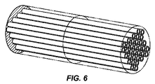
図面の図6は、中空ファイバで構成された吸着剤接触器を示している。複数本の中空管を多管式熱交換器の管束と同様な管束の状態に束にして組立体を形成することによって中空管構造体を形成することができる。注封材料、例えば中空ファイバ材料と適合性のあるエポキシによって中空管の各端部を終端させるのが良い。ガス流は、中空管の内部か外部かのいずれかに沿って流れるのが良いが、いずれの場合においても、組立体の長手方向軸線に平行である。中空管の壁を通るガス流が存在しないことが好ましい。 FIG. 6 of the drawings shows an adsorbent contactor composed of hollow fibers. A hollow tube structure can be formed by bundling a plurality of hollow tubes into a tube bundle similar to the tube bundle of a multi-tube heat exchanger to form an assembly. Each end of the hollow tube may be terminated with a potting material, for example an epoxy compatible with the hollow fiber material. The gas flow may flow along either the inside or the outside of the hollow tube, but in either case is parallel to the longitudinal axis of the assembly. Preferably there is no gas flow through the wall of the hollow tube.
中空ファイバ吸着剤構造体を形成する好ましい一方法は、先ず最初に、吸着剤、メソ細孔充填材及び熱質量体の混合マトリックスから中空ファイバを製作し、次に中空ファイバを束ね、次にファイバの外側周りの空間に注封材料を充填してガスがファイバの内部を通って流れることしかできないようにすることである。 One preferred method of forming a hollow fiber adsorbent structure is to first fabricate a hollow fiber from a mixed matrix of adsorbent, mesopore filler and thermal mass, then bundle the hollow fibers, and then fiber Is filled with potting material so that the gas can only flow through the interior of the fiber.
別の方法では、先ず最初に、中空ファイバを吸着剤、メソ細孔充填材及び熱質量体の混合マトリックスから製作し、次に中空ファイバを束ねてファイバの両端部を注封材料で終端させ、ガスがファイバの内側と外側の両方をこれに沿って流れることができるようにする。 In another method, the hollow fiber is first fabricated from a mixed matrix of adsorbent, mesopore filler, and thermal mass, then the hollow fiber is bundled and both ends of the fiber are terminated with a potting material, Allow gas to flow along both the inside and outside of the fiber.
中空ファイバ構造体を作る更に別の方法では、吸着剤とメソ細孔充填材の混合マトリックスを金属(例えば、皮下注射針)、セラミック、プラスチック等から成る郡から選択された非限定的な材料で構成された小径中空管の内側上に薄め塗布し、次にファイバの外側周りの空間に注封材料を充填してガスがファイバの内側しか通って流れることができないようにする。 In yet another method of making a hollow fiber structure, a mixed matrix of adsorbent and mesopore filler is made of a non-limiting material selected from a group consisting of metal (eg, hypodermic needle), ceramic, plastic, etc. Apply a thin coat on the inside of the constructed small diameter hollow tube and then fill the space around the outside of the fiber with potting material so that gas can only flow through the inside of the fiber.
構造体を作る更に別の方法では、金属、セラミック、プラスチック等から選択された材料で構成された小径の中空管の組立体を製作し、次に両端部を注封材料で又は溶接終端部で終端させ、次に管の内側に吸着剤及びメソ細孔充填材の混合マトリックスを薄め塗布する。 Yet another way to make the structure is to make a small diameter hollow tube assembly made of a material selected from metal, ceramic, plastic, etc., and then both ends with potting material or weld termination And then apply a thin layer of adsorbent and mesoporous filler mixed matrix to the inside of the tube.
さらに、別の方法では、吸着剤及びメソ細孔充填材の混合マトリックスを中空ファイバの内側と外側の両方に薄め塗布することを除き上述した方法と同一の方法で組立体を構成する。 In yet another method, the assembly is constructed in the same manner as described above, except that a mixed matrix of adsorbent and mesopore filler is applied thinly to both the inside and the outside of the hollow fiber.
これら構造化接触器は、RC‐PSAシステムのための単一の吸着剤床を種々の仕方で形成するために使用できる。一方法では、吸着剤床は、吸着剤床の長さに沿って作られた単一の構造化吸着剤接触器で構成される。別の方法では、吸着剤床は、吸着剤床の全長をもたらすよう互いに積み重ねられた構造化接触器の多数の短いセグメントで構成されるのが良い。この方法では、構造化接触器のセグメントを隣り合うセグメント相互間のギャップの有無にかかわらず設置することができる。隣り合うセグメント相互間に僅かなギャップ、例えば1000μm未満又は好ましくは500μm未満、更により好ましくは200μmのギャップを提供することにより、セグメント相互間のガスの再分布が可能になり、それにより構造化接触器のフローチャネル内の分布不良の影響を減少させることができる。 These structured contactors can be used to form a single adsorbent bed for the RC-PSA system in various ways. In one method, the adsorbent bed consists of a single structured adsorbent contactor made along the length of the adsorbent bed. Alternatively, the adsorbent bed may be composed of multiple short segments of structured contactors stacked together to provide the entire length of the adsorbent bed. In this way, structured contactor segments can be installed with or without gaps between adjacent segments. Providing a slight gap between adjacent segments, eg, less than 1000 μm or preferably less than 500 μm, and even more preferably 200 μm, allows gas redistribution between the segments, thereby providing structured contact The effects of maldistribution in the flow channel of the vessel can be reduced.
2種類以上の吸着性材料を利用した実施形態の場合、特徴B3として上述されている構造化吸着剤床内の種々の吸着性材料の配置は、RC‐PSAシステムの性能に影響を及ぼす場合がある。これらの実施形態では、2種類又は3種類以上の吸着剤を含む複合吸着剤床を使用することができ、各吸着剤は、供給物流からの互いに異なる汚染物質を優先的に吸着する。複合吸着剤床を数種類の互いに異なる仕方で、例えば、各々に互いに異なる吸着性材料が被着されたセグメント状構造化接触器を用いて構成できる。一例として、天然ガスからのCO2及びH2S除去の場合、吸着剤床の第1のセグメントがH2S除去のためのKIT‐6支持体上に被着されたアミン官能化吸着剤を含み、吸着剤床を構成する残りのセグメントがCO2除去のためのDDR吸着剤を含む複合吸着剤床を使用するのが良い。この実施形態では、H2Sは、供給物流が第1のセグメントを通過する際に供給物流から除去され、次に、供給物流が吸着剤床の残りのセグメントを通過しているときにCO2が供給物流から除去される。このように複合床を用いた場合の利点は、1つの吸着剤床セグメントから汚染物質を脱着することにより他方の吸着剤床セグメントのための分圧パージが得られ、それによりそれぞれの吸着剤床から他の汚染物質の除去が促進されるということにある。上述の実施例に関連して、説明すると、ブローダウンステップ中、DDRを含む床のセグメントから脱着されたCO2をアミン官能化吸着剤を含む第1のセグメントを通って向流方向に流すことができ、それにより実質的にH2Sのない分圧パージを提供し、それによりH2Sを複合吸着剤床の第1のセグメントから脱着させることができる。このように、複合床の第1のセグメントをH2Sの低いレベルまでクリーニングすることができ、その結果、ppmレベルのH2Sを含む高純度製品流を次の吸着ステップ中に生じさせることができる。複合床のH2S吸着セグメントのこの有効パージは、H2Sが吸着ステップ中に吸着剤床のDDRセグメント中に漏出しなくても有効であり、したがって、床のDDRセグメント中のCO2は、実質的にH2Sが含まれないようになる。 For embodiments utilizing more than one type of adsorbent material, the placement of the various adsorbent materials within the structured adsorbent bed described above as feature B3 may affect the performance of the RC-PSA system. is there. In these embodiments, a composite adsorbent bed comprising two or more adsorbents can be used, with each adsorbent preferentially adsorbing different contaminants from the feed stream. The composite adsorbent bed can be constructed in several different ways, for example using segmented structured contactors each having a different adsorbent material applied thereto. As an example, in the case of CO 2 and H 2 S removal from natural gas, an amine functionalized adsorbent in which the first segment of the adsorbent bed is deposited on a KIT-6 support for H 2 S removal. A composite adsorbent bed may be used in which the remaining segments comprising the adsorbent bed contain a DDR adsorbent for CO 2 removal. In this embodiment, H 2 S is removed from the feed stream as it passes through the first segment, and then CO 2 as it passes through the remaining segments of the adsorbent bed. Is removed from the supply stream. The advantage of using a composite bed in this way is that desorption of contaminants from one adsorbent bed segment results in a partial pressure purge for the other adsorbent bed segment, whereby each adsorbent bed segment The removal of other pollutants from is promoted. In connection with the above-described embodiment, to illustrate, during a blow down step, CO 2 desorbed from a segment of the bed containing DDR is flowed in a counter-current direction through a first segment containing an amine functionalized adsorbent. Thereby providing a partial pressure purge that is substantially free of H 2 S so that H 2 S can be desorbed from the first segment of the composite adsorbent bed. In this way, the first segment of the composite bed can be cleaned to a low level of H 2 S, resulting in a high purity product stream containing ppm levels of H 2 S during the next adsorption step. Can do. This effective purge of the H 2 S adsorption segment of the composite bed is effective even if H 2 S does not leak into the DDR segment of the adsorbent bed during the adsorption step, so the CO 2 in the bed DDR segment is , H 2 S is not substantially contained.
吸着剤床内の2種類の吸着性材料も又、一方の吸着性材料の量が他方の吸着性材料の量よりも実質的に多いことを条件として、吸着剤床全体にわたって材料を均一に分散させることによっても配置できる。例えば、上述したように天然ガスからのH2S及びCO2除去の場合、アミン官能化材料よりも約10倍のDDRが必要である。好ましい実施形態では、H2S選択性吸着剤の量は、CO2選択性吸着剤量の五分の一未満である。これら材料が吸着剤接触器に沿って一様に混合されると共に分布される場合、CO2が吸着剤床中に分布して設けられたアミン官能化材料の分圧パージを提供してH2Sを実質的にクリーニングし、それにより高純度メタンを次の吸着ステップで得ることができるという同じ結果が達成される。 The two adsorbent materials in the adsorbent bed also distribute the material evenly across the adsorbent bed, provided that the amount of one adsorbent material is substantially greater than the amount of the other adsorbent material. Can also be arranged. For example, as described above, removal of H 2 S and CO 2 from natural gas requires about 10 times more DDR than amine functionalized material. In a preferred embodiment, the amount of H 2 S selective adsorbent is less than one fifth of the CO 2 selective adsorbent amount. When these materials are uniformly mixed and distributed along the adsorbent contactor, CO 2 provides a partial pressure purge of the amine functionalized material provided distributed in the adsorbent bed to provide H 2. The same result is achieved in that S is substantially cleaned, whereby high purity methane can be obtained in the next adsorption step.
RC‐PSAシステムの製品回収率を特徴B4として上述したようにメソ細孔充填材の使用により高めることができ、この特徴B4は、接着剤床中のボイド空間を減少させるために利用できる。その結果、ボイド空間内に取り込まれた製品ガスの量が減少し、その結果、再生中に汚染物質と共に失われる製品ガスが少なくなり、それにより製品ガスの回収率が向上する。メソ細孔充填材の使用は、米国特許出願公開第2008/0282892号明細書、同第2008/0282885号明細書及び同第2008/028286号明細書に記載されており、これら米国特許出願公開の各々を参照により引用し、その記載内容全体を本明細書の一部とする。吸着剤チャネル壁内に存在する掃過できない(非掃過の)ボイド空間をメソ細孔及びマクロ細孔により占められる全容積によって定めることができる。メソ細孔は、IUPACによって20〜500オングストロームサイズ範囲のサイズを持つ細孔であると定められる。マクロ細孔は、本明細書においては、500オングストロームを超え且つ1ミクロン未満のサイズを持つ細孔であると定義される。フローチャネルのサイズが1ミクロンを超えているので、これらフローチャネルは、マクロ細孔容積の一部とは見なされない。非掃過ボイド空間は、本明細書においては、直径が20オングストローム〜10,000オングストローム(1ミクロン)の吸着剤中の細孔により占められる開放細孔容積を吸着剤構造体中の関連のメソ細孔及びマクロ細孔を含む吸着性材料により占められる接触器の全容積で除算して得られるものとして定義される。以下ひとまとめにメソ細孔と呼ぶ非掃過温度空間を減少させるには、粒子相互間のメソ細孔を充填して開放容積を減少させる一方で、吸着剤層中の迅速なガス輸送を可能にするのが良い。非掃過ボイド空間のこの充填は、迅速な脱着ステップ中に失われる所望の製品の量を許容レベルまで減少させると共に脱着後における高度の吸着剤床純度の達成を可能にする上で望ましい。このようなメソ細孔充填は、種々の仕方で達成できる。例えば、ポリマー充填材、例えばシリコンゴム又は固有の多孔度を有するポリマーをH2S及びCO2の迅速拡散と共に利用するのが良い。変形例として、メソ細孔度及び/又はマクロ細孔度を有する合成炭素を用いてもボイド空間を充填することができる。さらに別の方法では、ボイド空間を小さなサイズの不活性固体で充填し又はボイド空間を所望のガスが迅速に拡散する補充可能な液体(例えば、水、溶剤又は油)をボイド空間に充填することである。好ましくは、接着剤床内のボイド空間を開放細孔容積の約40容量%(vol.%)以下、好ましくは30vol.%未満、より好ましくは20vol.%未満、更により好ましくは10vol.%未満、最も好ましくは約5vol.%以下に減少させる。 The product recovery of the RC-PSA system can be enhanced by using mesopore filler as described above as feature B4, which feature B4 can be used to reduce void space in the adhesive bed. As a result, the amount of product gas taken into the void space is reduced, resulting in less product gas being lost along with contaminants during regeneration, thereby improving product gas recovery. The use of mesopore fillers is described in U.S. Patent Application Publication Nos. 2008/0282892, 2008/0282885, and 2008/028286. Each is cited by reference and the entire contents thereof are made a part of this specification. The non-swept (unswept) void space present in the adsorbent channel wall can be defined by the total volume occupied by mesopores and macropores. Mesopores are defined by IUPAC as pores having a size in the 20-500 Angstrom size range. Macropores are defined herein as pores having a size greater than 500 angstroms and less than 1 micron. These flow channels are not considered part of the macropore volume since the size of the flow channels exceeds 1 micron. The non-swept void space herein refers to the open pore volume occupied by pores in the adsorbent having a diameter of 20 Angstroms to 10,000 Angstroms (1 micron) and the associated meso in the adsorbent structure. Defined as obtained by dividing by the total volume of the contactor occupied by the adsorbent material including pores and macropores. To reduce the non-swept temperature space, collectively referred to below as mesopores, fill the mesopores between particles to reduce the open volume while allowing rapid gas transport in the adsorbent layer. Good to do. This filling of the non-swept void space is desirable to reduce the amount of desired product lost during the rapid desorption step to an acceptable level and to allow a high degree of adsorbent bed purity to be achieved after desorption. Such mesopore filling can be achieved in various ways. For example, polymer fillers such as silicon rubber or polymers with inherent porosity may be utilized with rapid diffusion of H 2 S and CO 2 . As a modification, the void space can also be filled using synthetic carbon having mesoporosity and / or macroporosity. In yet another method, the void space is filled with a small sized inert solid or the void space is filled with a replenishable liquid (eg, water, solvent or oil) that rapidly diffuses the desired gas. It is. Preferably, the void space in the adhesive bed is not greater than about 40 volume% (vol.%) Of the open pore volume, preferably 30 vol. %, More preferably 20 vol. %, Even more preferably 10 vol. %, Most preferably about 5 vol. Reduce to less than%.
吸着剤構造及び材料に関する特徴に加えて、種々の吸着システム構成又は構成上の特徴を他の特徴に加えて又はプロセスに対する別の改善策として利用することができる。このような一実施形態は、特徴C1として上述したRC‐PSAシステムからの回収率を向上させるためのRC‐PSAユニットの直列配置を含むのが良い。一例として、RC‐PSAユニットの直列配置を利用すると、非製品流を第1のRC‐PSAユニットから第2のRC‐PSAユニットに通して第1のRC‐PSAユニットの非製品流から製品を除くことによって標的ガス又は製品の回収率及び純度を高めることができる。一例として、酸性ガスを天然ガス流から除去してこのシステムの第1のRC‐PSAユニット中に高純度のメタン流を生じさせることができる。第1のRC‐PSAユニットからの酸性ガスは、所与のフラクションのメタンを含む場合があり、これは、第2のRC‐PSAユニットを用いて除去できる。第2のRC‐PSAユニットからのメタン製品を再循環させることができ又は施設内のどこか別の場所で利用することができ、酸性ガスを第2のRC‐PSAユニットから排出することができ又は処分のために運び出すことができる。第2のRC‐PSAユニットを用いてメタンを捕捉することによって、RC‐PSAシステム全体は、高圧天然ガスを得るための高い製品回収率及び高い製品純度さえも達成する。 In addition to features related to adsorbent structure and materials, various adsorption system configurations or structural features can be utilized in addition to other features or as another improvement to the process. One such embodiment may include a series arrangement of RC-PSA units to improve recovery from the RC-PSA system described above as feature C1. As an example, using a series arrangement of RC-PSA units, the non-product stream is passed from the first RC-PSA unit to the second RC-PSA unit, and the product is removed from the non-product stream of the first RC-PSA unit. By removing, the recovery rate and purity of the target gas or product can be increased. As an example, acid gas can be removed from the natural gas stream to produce a high purity methane stream in the first RC-PSA unit of the system. The acid gas from the first RC-PSA unit may contain a given fraction of methane, which can be removed using the second RC-PSA unit. Methane product from the second RC-PSA unit can be recycled or used elsewhere in the facility, and acid gases can be discharged from the second RC-PSA unit Or it can be carried out for disposal. By capturing methane using a second RC-PSA unit, the entire RC-PSA system achieves high product recovery and even high product purity to obtain high pressure natural gas.
また、別の特徴として、均圧化容器又はタンクを利用すると特徴C2として上述したRC‐PSAシステムの生産性を高めると共に必要なサイクル時間全体を短縮することができる。米国特許出願第61/594,824号明細書に記載されているように、1つ又は2つ以上の独立圧力容器をRC‐PSAシステム内の吸着剤床について各均圧化ステップのために提供するのが良く、このような米国特許出願を参照により引用し、その記載内容を本明細書の一部とする。即ち、均圧化容器又はタンクと呼ばれる専用圧力容器は、吸着剤床の1つに直接連結される。脱着ステップ中に吸着剤床から引き出されたガスは、均圧化タンク内に一時的に貯蔵され、次に、同一の吸着剤床の再加圧のためのサイクル中に後で用いられる。管類及び弁類に関する距離が専用均圧化容器の使用により短くなるので、吸着剤床と均圧化タンクとの間の均圧化ステップの時間間隔が代表的には、2つの吸着剤床相互間の均圧化に必要な時間よりも短く、したがってサイクル時間全体を短くすることができる。その結果、吸着剤床内で利用される吸着性材料の量が減少し、スイング吸着システムのサイズ及び重量全体を減少させることができ、他方、性能を高めることができる(低いパージ流量、低い再循環圧縮等)。さらに、RC‐PSAシステムのための管及び弁の量が減少する。と言うのは、床間連結が均圧化ステップに関して不要だからである。 As another feature, the use of a pressure equalizing vessel or tank can increase the productivity of the RC-PSA system described above as feature C2 and shorten the entire required cycle time. One or more independent pressure vessels are provided for each pressure equalization step for the adsorbent bed in the RC-PSA system, as described in US patent application Ser. No. 61 / 594,824. Such US patent applications are hereby incorporated by reference, the contents of which are hereby incorporated by reference. That is, a dedicated pressure vessel called a pressure equalization vessel or tank is directly connected to one of the adsorbent beds. The gas withdrawn from the adsorbent bed during the desorption step is temporarily stored in a pressure equalizing tank and then used later during a cycle for repressurization of the same adsorbent bed. Since the distance for tubing and valves is reduced by the use of a dedicated pressure equalization vessel, the time interval of the pressure equalization step between the adsorbent bed and the pressure equalization tank is typically two adsorbent beds. Shorter than the time required for pressure equalization between each other, and thus the overall cycle time can be shortened. As a result, the amount of adsorbent material utilized in the adsorbent bed can be reduced, reducing the overall size and weight of the swing adsorption system, while increasing performance (low purge flow, low recycle). Circulation compression, etc.). In addition, the amount of tubing and valves for the RC-PSA system is reduced. This is because the connection between floors is not necessary for the pressure equalization step.
上述の特徴をPSAシステム中に組み込むと高圧天然ガス処理のための性能を向上させることができ、それにより高い回収率、高い純度又は高い回収率と高い純度の両方が得られる分離が可能である。図7〜図9は、本明細書において説明した特徴を分離ためにどのように組み合わせれば良いかを示す例示のPSAシステムの略図である。図7では、高いメタン回収率は、PSAシステム700を回収パージ(特徴A2)を備えた迅速サイクル(特徴A1)で適当な中間圧力(特徴A5)において作動させると共に多数回のブローダウンステップ(特徴A6)を用いることによって提供される。CO2について反応速度論的選択性を示すゼオライト(特徴B1)で被覆された構造化接触器(特徴B2)が用いられ、ボイド空間は、メソ細孔充填材(特徴B4)の使用により減少する。RC‐PSAシステム700の例示の実施形態を97%超えるメタン回収率を達成するために30%酸性ガスを含む天然ガスを55barで処理するための実施例1及び実施例2において更に説明する。
Incorporating the features described above into a PSA system can improve performance for high pressure natural gas processing, thereby allowing separations that provide high recovery, high purity or both high recovery and high purity. . 7-9 are schematic diagrams of an exemplary PSA system showing how the features described herein may be combined for separation. In FIG. 7, the high methane recovery rate allows the
図8に示されている別の実施例では、システム800内の一連の2つのPSAユニットを用いて高いメタン回収率と高い製品純度の両方が達成される。PSAユニット801,821は、迅速サイクル(特徴A1)、回収パージ(特徴A2)、製品パージ(特徴A3)、パージ圧力の選択(特徴A5)、CO2の反応速度論的分離のための別々の材料を含む構造化吸着剤接触器(特徴B2)、2つの別々のセグメント(特徴B3)の状態で接触器内に配置されたH2S平衡吸着(特徴B1)、メソ細孔充填材を組み込んでボイド容積を減少させること(特徴B4)を含む上述した特徴を利用し、回収率を向上させる。メタン回収率を増大させるには、2つのPSAユニットを直列状態で利用し(特徴C1)、それにより第2のPSAユニット821を用いて第1のPSAユニット801からの酸性ガス流中に失われるメタンを捕捉する。PSAシステムは又、サイクル時間を短縮すると共に生産性を向上させるために均圧化タンク(特徴C2)を利用するのが良い。RC‐PSAシステム800の性能及び詳細は、12%CO2及び0.01〜0.1%H2Sを含む天然ガスを処理して1.5%未満のCO2及び4ppm未満のH2Sを含むメタンを生じさせる一方で99%を超える回収率を達成するために実施例3及び実施例4において説明されている。
In another embodiment shown in FIG. 8, both high methane recovery and high product purity are achieved using a series of two PSA units in
図9に示されている更に別の実施形態では、単一のPSAユニット900で高いメタン回収率と高い製品純度の両方が達成される。このPSAユニットは、適当な中間圧力(特徴A5)で回収パージ(特徴A2)を含む迅速サイクルモード(特徴A1)で作動させ、次に高い製品純度を達成するよう真空圧力(特徴A4)へのブローダウンを行う。構造化吸着剤接触器(特徴B2)をCO2の反応速度論的分離及び2つの別々のセグメント(特徴B3)の状態で接触器内に配置されたH2Sの平衡吸着(特徴B1)のための2つの特定の材料に用い、メソ細孔充填材を混入してボイド空間(特徴B4)を減少させると共に回収率を向上させる。均圧化タンク(特徴C2)も又、必要なサイクル時間を短縮し、それによりシステムの生産性を向上させるために利用できる。RC‐PSAシステム900の性能及び詳細は、12%CO2及び0.01〜0.1%H2Sを含む天然ガスを処理して1.5%未満のCO2及び4ppm未満のH2Sを含むメタンを生じさせる一方で99%を超える回収率を達成するために実施例5において説明されている。
In yet another embodiment shown in FIG. 9, both high methane recovery and high product purity are achieved with a
例示目的で提供され、本発明を限定するものとは見なされない以下の実施例を参照すると、本発明を良好に理解することができる。 The invention can be better understood with reference to the following examples, which are provided for purposes of illustration and are not to be considered as limiting the invention.
実施例1
この実施例は、図7のRC‐PSAシステム700を用いた高圧での天然ガスからのCO2及びH2Sの除去の仕方を示している。図7の単純化されたプロセス流れ図を参照すると、RC‐PSAユニット701は、供給物流から汚染物質を除去するよう種々の圧縮機710a〜710eと一緒に利用される。RC‐PSAユニット701は、以下に詳細に説明するように弁及び管を介して互いに連結された多数の吸着剤床を有している。作動させるため、供給物流を導管702,704によりRC‐PSAユニット701に流す。供給物流は、好ましくは、天然ガスを含み、天然ガスは、圧縮機710aと関連した回収パージ出口導管703からの再循環流と混ぜ合わされるのが良い。メタンに富んだ精製された製品流が吸着剤床、RC‐PSAユニット701の内部述弁及び管相互間の圧力降下に起因して僅かに減少した圧力で導管706を通ってRC‐PSAユニット701から出る。この実施例では、導管702を通って流入する供給物ガスは、30%酸性ガス(CO2+H2S)及び70%CH4を含んでいる。供給物流及び再循環流の圧力は、約55bar‐aである。導管706を通って出る製品流は、6%酸性ガス及び94%CH4を含み、圧力は、約54bar‐aである。
Example 1
This example illustrates how CO 2 and H 2 S are removed from natural gas at high pressure using the RC-
回収パージ流を導管708によりRC‐PSAユニット701に流すのが良い。このパージ流は、酸性ガス(CO2及び/又はH2S)に富んでおり、このようなパージ流は、以下に詳細に説明するRC‐PSAサイクル中のブローダウンステップから出る流出液で構成されるのが良い。回収パージ流の目的は、吸着剤接触器チャネル及び吸着剤層中のボイド空間からメタン及び他の炭化水素を掃過することにある。このパージからの出力は、圧縮機710a内で圧縮されて導管703を介してRC‐PSAユニットの供給部に再循環して戻される。このように、メタンは、酸性ガスと共に失われることなく捕捉され、したがって、RC‐PSAシステムの回収率が向上する。
The recovered purge stream may flow to RC-PSA unit 701 via conduit 708. This purge stream is rich in acid gases (CO 2 and / or H 2 S), such purge stream consisting of the effluent exiting the blow-down step during the RC-PSA cycle described in detail below. It is good to be done. The purpose of the recovery purge stream is to sweep methane and other hydrocarbons from the adsorbent contactor channel and void space in the adsorbent layer. The output from this purge is compressed in
RC‐PSAユニット701から脱着された酸性ガスは、3つの互いに異なる圧力レベルで出て処分のために酸性ガスを圧縮するために必要な電力消費量を最小限に抑える。最低圧力は、汚染物質の脱着を増大させて次の吸着ステップにおいて製品純度を高めるよう約1bar‐aに設定される。残りの2つのブローダウンステップに関する圧力レベルは、酸性ガス圧縮機との一体化を最適化して電力消費量を減少させるよう選択されている。代表的な酸性ガス圧縮機は、約3の圧力比で動作し、したがって、ブローダウン圧力レベルは、3bar‐a及び9bar‐aである。圧力比は、吐き出し圧力を吸い込み圧力で除算して得られる値である。図7に示されているように、1bar‐aでの低圧排出物は、圧縮機710b内で圧縮されて約3bar‐aで中間圧力排出物と混合されて圧縮機710c内で圧縮される。圧縮機710cからの排出物は、約9bar‐aで高圧排出物と混合されて圧縮機710d内で圧縮される。圧縮機710dの出力は、約19bar‐aであるのが良く、この出力は、パージ流として導管708に送られて圧縮機710eに送られて更に圧縮され、その後更に処理される一部分を含むのが良い(例えば、処分ウェル、パイプライン及び/又はその他に注入される酸性ガス)。
The acid gas desorbed from the RC-PSA unit 701 exits at three different pressure levels to minimize the power consumption required to compress the acid gas for disposal. The minimum pressure is set to about 1 bar-a to increase contaminant desorption and increase product purity in the next adsorption step. The pressure levels for the remaining two blowdown steps are selected to optimize integration with the acid gas compressor and reduce power consumption. A typical acid gas compressor operates at a pressure ratio of about 3, so the blowdown pressure levels are 3 bar-a and 9 bar-a. The pressure ratio is a value obtained by dividing the discharge pressure by the suction pressure. As shown in FIG. 7, the low pressure discharge at 1 bar-a is compressed in
各RC‐PSAユニット701は、14個の吸着剤床で構成され、これら吸着剤床の各々は、複数本のガスフローチャネルを備えた構造化接触器で構成されている。ガスフローチャネルの水力直径は、20〜1000ミクロン、好ましくは25〜400ミクロン、更により好ましくは40〜125ミクロンである。接触器を貫通して設けられたガスフローチャネルの全長は、0.2〜3メートル、好ましくは0.5〜1.5メートルであり、最も好ましくは、0.75〜1.25メートルである。構造化接触器は、各セグメントが複数本のフローチャネルを有し、ガスが一セグメント中のフローチャネルから別個のセグメント中のフローチャネルまで順次流れるようその長さに沿ってセグメント化されているのが良い。接触器の長さに沿って1〜10個のセグメントが設けられるのが良い。吸着剤床の入口側においてフローチャネルを通るガスの物理的流速は、1〜10メートル/秒であり、好ましくは2〜5メートル/秒である。フローチャネルを通るガスの流体抵抗により、吸着ステップ中、供給物圧力、供給物粘度、チャネル水力直径及びチャネル全長と入口供給物速度の組み合わせにより計算して8bar‐a未満、好ましくは4bar‐a未満、より好ましくは2bar‐a未満の圧力降下が生じる。 Each RC-PSA unit 701 is composed of 14 adsorbent beds, each of which is composed of a structured contactor with a plurality of gas flow channels. The hydraulic diameter of the gas flow channel is 20 to 1000 microns, preferably 25 to 400 microns, and even more preferably 40 to 125 microns. The total length of the gas flow channel provided through the contactor is 0.2 to 3 meters, preferably 0.5 to 1.5 meters, most preferably 0.75 to 1.25 meters. . The structured contactor is segmented along its length so that each segment has multiple flow channels and gas flows sequentially from the flow channel in one segment to the flow channel in a separate segment. Is good. 1 to 10 segments may be provided along the length of the contactor. The physical flow rate of the gas through the flow channel on the inlet side of the adsorbent bed is 1-10 meters / second, preferably 2-5 meters / second. Due to the fluid resistance of the gas through the flow channel, less than 8 bar-a, preferably less than 4 bar-a, calculated by the combination of feed pressure, feed viscosity, channel hydraulic diameter and total channel length and inlet feed rate during the adsorption step More preferably, a pressure drop of less than 2 bar-a occurs.
構造化吸着剤接触器内のガスフローチャネルは、CO2及びH2Sに対して選択性を示す吸着性材料を含む層で作られており、この層は、構造化接触器壁上に位置しても良く又はその少なくとも何分の一かの一部であっても良い。この層は、メソ細孔充填材料を更に含むのが良く、このようなメソ細孔充填材料は、層中のボイド空間を30容量%未満、より好ましくは20容量%未満、より好ましくは10容量%未満又は最も好ましくは4容量%未満で減少させる。層の平均厚さは、25〜450ミクロン、好ましくは30〜200ミクロン、最も好ましくは50〜125ミクロンであるのが良い。好ましい実施形態では、吸着性材料は、ゼオライトであり、CO2に関して50を超え、好ましくは100を超え、更により好ましくは200を超える反応速度論的選択性比を有する。反応速度論的選択性比は、汚染物質、例えばCO2の拡散速度を、製品、例えばメタンの拡散速度で除算した値である。吸着ステップ中、チャネルの長さに沿う吸着剤中へのCO2及びH2Sの平均装填量の変化は、1g当たり0.2ミリモル(m mol/g)を超え、より好ましくは0.5m mol/gを超え、最も好ましくは1m mol/gを超え、この場合、平均装填量は、吸着剤の1g当たり吸着される汚染物質のミリモルとして表される。 The gas flow channel in the structured adsorbent contactor is made of a layer containing an adsorbent material that is selective for CO 2 and H 2 S, and this layer is located on the structured contactor wall. Or it may be part of at least a fraction of it. The layer may further comprise a mesopore filling material, such mesopore filling material having less than 30 volume% void space in the layer, more preferably less than 20 volume%, more preferably 10 volume. %, Or most preferably less than 4% by volume. The average thickness of the layer should be 25 to 450 microns, preferably 30 to 200 microns, most preferably 50 to 125 microns. In a preferred embodiment, the adsorbent material is a zeolite, more than 50 with respect to CO 2, preferably greater than 100, even more preferably kinetic selectivity ratio greater than 200. Kinetic selectivity ratio contaminants, the diffusion rate of for example CO 2, the product, for example a value obtained by dividing the rate of diffusion of methane. During the adsorption step, the change in average charge of CO 2 and H 2 S into the adsorbent along the length of the channel is greater than 0.2 millimoles per gram (m mol / g), more preferably 0.5 m More than mol / g, most preferably more than 1 mmol / g, where the average loading is expressed as millimoles of contaminant adsorbed per gram of adsorbent.
RC‐PSAユニット701を作動させるには一連のステップを迅速に繰り返し、このような一連のステップは、吸着ステップ及び次のサイクルでの吸着ステップに先立って吸着剤床を再生する多数のステップを含む。同じ一連のステップを各吸着剤床によって連続的に実施し、各層に関するサイクルのタイミングを他の床と同期させて供給物流、製品流及びパージ流の連続した流れを生じさせるのが良い。正確なステップ及びサイクルタイミングの選択は、供給物流のガス組成、製品仕様、汚染物質処分及び全体的炭化水素回収率で決まる。この実施例では、RC‐PSAユニット701に関し、連続流れ作業を行うためにサイクルを完了するには14個の吸着剤床が必要である。
To operate the RC-PSA unit 701, a series of steps is rapidly repeated, and such a series of steps includes a number of steps to regenerate the adsorbent bed prior to the adsorption step and the adsorption step in the next cycle. . The same series of steps may be performed continuously by each adsorbent bed, and the cycle timing for each layer may be synchronized with the other beds to produce a continuous stream of feed stream, product stream and purge stream. The exact step and cycle timing selection depends on the gas composition of the feed stream, product specifications, pollutant disposal and overall hydrocarbon recovery. In this example, for the RC-
単一吸着剤床に関するサイクルステップが吸着剤床の圧力と時間との関係を表すグラフ図を用いて示されており、これは、図10に示されている。FD(供給物流に関する)として示された接着剤ステップ中、酸性ガスは、接着剤床中に吸着され、精製されたメタン製品が作られる。製品流中への酸性ガスのかなりの漏出が生じる前に供給物流の流れを停止させ、吸着剤床を符号E1及びE2で示されている2つの均圧化ステップによって減圧する。製品流中への酸性ガスのかなりの漏出は、吸着剤床が50%を超える装填状態にあるとき、好ましくは75%を超える装填状態にあるときに起こる。各ステップ後に短時間の保持が設けられ、これは、図示されていない。均圧化ステップ後、吸着剤層中のフローチャネル及びボイド空間内に残存しているメタンを回収するためにPとして示されている回収パージステップを実施する。次に、吸着剤床を3つのブローダウンステップによって減圧して圧力を減少させ、それにより酸性ガスを吸着剤床から脱着させ、これは、BDで示されている。酸性ガスを可能な程度まで脱着させた後、吸着剤床をR1,R2として示されている2つの再加圧ステップ及びFRとして示されている供給物再加圧ステップによって再加圧する。2つの再加圧ステップR1,R2のためのガス源は、再加圧ステップE1,E2を同時に受けている別の吸着剤床に由来する。供給物再加圧ステップのためのガスは、図7の導管704を介して供給物流からRC‐PSAユニット中に得られる。
The cycle steps for a single adsorbent bed are shown using a graphical representation of the relationship between adsorbent bed pressure and time, which is shown in FIG. During the adhesive step, designated as FD (for the feed stream), acid gas is adsorbed into the adhesive bed to produce a purified methane product. The feed stream flow is stopped before significant leakage of acid gas into the product stream occurs, and the adsorbent bed is depressurized by two pressure equalization steps, denoted E1 and E2. Significant leakage of acid gas into the product stream occurs when the adsorbent bed is in a loading state greater than 50%, and preferably in a loading state greater than 75%. A brief hold is provided after each step, which is not shown. After the pressure equalization step, a recovery purge step, indicated as P, is performed to recover the methane remaining in the flow channel and void space in the adsorbent layer. The adsorbent bed is then depressurized by three blow-down steps to reduce the pressure, thereby desorbing the acidic gas from the adsorbent bed, which is indicated by BD. After desorbing the acid gas to the extent possible, the adsorbent bed is repressurized by two repressurization steps, denoted as R1, R2, and a feed repressurization step, denoted as FR. The gas source for the two repressurization steps R1, R2 comes from a separate adsorbent bed that is undergoing the repressurization steps E1, E2 simultaneously. Gas for the feed repressurization step is obtained in the RC-PSA unit from the feed stream via
14個の吸着剤床の各々に関するタイミングは、供給物流、製品流及びパージ流が連続であるように同期する。全部で14個の吸着剤床のサイクルスケジュールが図11A及び図11Bに示されている。2つの群をなす吸着剤床1101,1102が示されており、第1群1101に属する吸着剤床は、シーケンスグラフの頂部に1〜7で示され、第2群1102に属する吸着剤床は、シーケンスグラフの底部に8〜14で示されている。図11Aは、参照符号Dで示されているように、図11Bと連続関係にあるシーケンスの一部分である。定常作動中、2つの吸着剤床は、吸着ステップを行っており、この場合、酸性ガスは、供給物流から除去されて精製されたメタン製品が得られる。各吸着剤床に関するサイクルのタイミングは、連続供給物及び製品流が達成されるようステージングされる。例えば、図11Aの床2は、床1が吸着ステップを停止した直後に吸着ステップ(FDで示されている)の開始等をする。同様に、パージステップ及びブローダウン流に関して連続した流れが酸性ガス圧縮機に提供される。吸着剤床相互間のサイクルのタイミングも又、1つの床に関する第1の均圧化ステップE1が別の床の再加圧ステップR1と一致して減圧ステップ中に取り出されたガスが別の床を再加圧するために用いられるよう同期される。例えば、図11Aの吸着剤床7は、吸着剤床2が再加圧ステップR1を行うのと同時に均圧化ステップE1を行う。
The timing for each of the 14 adsorbent beds is synchronized so that the feed stream, product stream and purge stream are continuous. A cycle schedule for a total of 14 adsorbent beds is shown in FIGS. 11A and 11B. Two groups of
サイクル中のステップの各々に関する圧力レベル、流れ方向及び持続時間について以下に更に説明する。以下のサイクルに関する説明では、「並流」という用語は、床の供給物側から製品側へのガスの流れを意味し、「向流」という用語は、その逆の方向の流れを意味している。以下は、好ましい一サイクルである。
FD:第1の吸着剤床からの55bar‐aでのCO2の吸着及び精製メタンの生産(並流)。
E1:第1の吸着剤床を約55bar‐aから約35.5bar‐aに減圧してガスを別の吸着剤床に送って約19bar‐aから約35.5bar‐aに加圧する(並流)。
E2:第1の吸着剤床を約35.5bar‐aから約19bar‐aに減圧してガスを別の吸着剤床に送って約1.2bar‐aから約19bar‐aに加圧する(並流)。
P:第1の吸着剤床を約19bar‐aで9bar‐aでのステップBD1からのガスの一部分でパージし、第1の吸着剤床は、パージ圧力に圧縮される。パージステップ中に吸着剤床から押し退けられたガスは、55bar‐aに圧縮され、そして供給物導管に再循環される(並流)。
BD1:第1の吸着剤床を約19bar‐aから約9bar‐aにブローダウンし又は減圧する。脱着したガスを酸性ガス圧縮機の第3段に排出する(向流)。
BD2:第1の吸着剤床を約9bar‐aから約3bar‐aにブローダウンし又は減圧する。脱着したガスを酸性ガス圧縮機の第2段に排出する(向流)。
BD3:第1の吸着剤床を約3bar‐aから約1.2bar‐aにブローダウンし又は減圧する。脱着したガスを酸性ガス圧縮機の第1段に排出する(向流)。
R2:ステップE2を行っている更に別の吸着剤床から引き出されたガスを用いて第1の吸着剤床を約1.2bar‐aから約19bar‐aに再加圧する(向流)。
R1:ステップE1を行っている更に別の吸着剤床から引き出されたガスを用いて第1の吸着剤床を約19bar‐aから約35.5bar‐aに再加圧する(向流)。
FR:供給物導管からのガスを用いて第1の吸着剤床を約35.5bar‐aから約55bar‐aに再加圧する(並流)。
The pressure level, flow direction and duration for each of the steps in the cycle are further described below. In the following description of the cycle, the term “cocurrent” means the flow of gas from the feed side to the product side of the bed, and the term “countercurrent” means the flow in the opposite direction. Yes. The following is a preferred cycle.
FD: Adsorption of CO 2 at 55 bar-a from the first adsorbent bed and production of purified methane (cocurrent).
E1: Depressurize the first adsorbent bed from about 55 bar-a to about 35.5 bar-a and send gas to another adsorbent bed to pressurize from about 19 bar-a to about 35.5 bar-a (normal Flow).
E2: Depressurize first adsorbent bed from about 35.5 bar-a to about 19 bar-a and send gas to another adsorbent bed to pressurize from about 1.2 bar-a to about 19 bar-a (normal Flow).
P: The first adsorbent bed is purged at about 19 bar-a with a portion of the gas from step BD1 at 9 bar-a, and the first adsorbent bed is compressed to the purge pressure. The gas displaced from the adsorbent bed during the purge step is compressed to 55 bar-a and recycled to the feed conduit (cocurrent).
BD1: Blow down or depressurize first adsorbent bed from about 19 bar-a to about 9 bar-a. The desorbed gas is discharged to the third stage of the acidic gas compressor (counterflow).
BD2: Blow down or depressurize the first adsorbent bed from about 9 bar-a to about 3 bar-a. The desorbed gas is discharged to the second stage of the acidic gas compressor (counterflow).
BD3: Blow down or depressurize first adsorbent bed from about 3 bar-a to about 1.2 bar-a. The desorbed gas is discharged to the first stage of the acid gas compressor (counterflow).
R2: Repressurize the first adsorbent bed from about 1.2 bar-a to about 19 bar-a (countercurrent) using gas drawn from yet another adsorbent bed performing step E2.
R1: Repressurize the first adsorbent bed from about 19 bar-a to about 35.5 bar-a (countercurrent) with the gas drawn from yet another adsorbent bed performing step E1.
FR: Repressurize the first adsorbent bed from about 35.5 bar-a to about 55 bar-a using gas from the feed conduit (cocurrent).
サイクル中の各ステップの持続時間は、次の通りである。
FD:1.5秒間の吸着
H1:0.25秒間の保持
E1:0.75秒間の減圧
E2:0.75秒間の減圧
P:0.75秒間のパージ
H2:0.25秒間の保持
BD1:0.75秒間のブローダウン
BD2:1.25秒間のブローダウン
BD3:2.0秒間のブローダウン
H3:0.25秒間の保持
R2:0.75秒間の再加圧
R1:0.75秒間の再加圧
FR:0.50秒間の再加圧
The duration of each step in the cycle is as follows:
FD: Adsorption for 1.5 seconds H1: Hold for 0.25 seconds E1: Reduce pressure for 0.75 seconds E2: Reduce pressure for 0.75 seconds P: Purge for 0.75 seconds H2: Hold for 0.25 seconds BD1: 0.75 second blowdown BD2: 1.25 second blowdown BD3: 2.0 second blowdown H3: 0.25 second hold R2: 0.75 second repressurization R1: 0.75 second Repressurization FR: 0.50 second repressurization
全部で10.5が上述のサイクルステップを完了させるのに必要である。この実施例では、吸着剤ステップ持続時間は、CO2及びメタンの拡散速度で設定され、この場合、吸着ステップの短い長さにより、迅速に拡散しているCO2分子が吸着性材料内の平衡吸着能力に達し、その後、ゆっくりと拡散するメタンが実質的に吸着性材料中に拡散することができる。吸着ステップ後に吸着剤床内の圧力をできるだけ迅速に減少させて吸着剤粒子中へのメタンのそれ以上の拡散を減少させ、その結果、メタンの損失を減少させるようにすることが好ましい。さらに、再生ステップに要する全時間は、吸着剤床の生産性を最大にするようできるだけ短いことが好ましい。均圧化ステップの全てに要する全時間間隔は、吸着ステップの10倍未満、好ましくは5倍未満であることが好ましい。最も好ましくは、均圧化ステップの全てに要する全時間は、吸着ステップの全時間よりも短い。また、再加圧ステップの全てに要する全時間は、吸着ステップの全時間の10倍未満、好ましくは5倍未満である。再加圧ステップの全てに要する全時間は、吸着ステップの全時間よりも短いことが最も好ましい。 A total of 10.5 is required to complete the above cycle steps. In this example, the adsorbent step duration is set by the diffusion rate of CO 2 and methane, where the short length of the adsorption step causes the rapidly diffusing CO 2 molecules to equilibrate within the adsorbent material. Methane that reaches adsorption capacity and then slowly diffuses can substantially diffuse into the adsorbent material. It is preferred to reduce the pressure in the adsorbent bed as quickly as possible after the adsorption step to reduce further diffusion of methane into the adsorbent particles, thereby reducing methane loss. Furthermore, the total time required for the regeneration step is preferably as short as possible to maximize the productivity of the adsorbent bed. The total time interval required for all pressure equalization steps is preferably less than 10 times, preferably less than 5 times that of the adsorption step. Most preferably, the total time required for all of the pressure equalization steps is shorter than the total time of the adsorption step. Further, the total time required for all the repressurization steps is less than 10 times, preferably less than 5 times the total time of the adsorption step. Most preferably, the total time required for all repressurization steps is shorter than the total time for the adsorption step.
この実施例において説明しているRC‐PSAシステムの結果としての性能は、上述のパラメータを用いてシミュレーションにより予測された。14個の吸着剤床を有する単一のRC‐PSAユニットは、30%酸性ガス及び70%メタンを含む150MSCFDの供給物ガスを処理して約5.4%酸性ガス及び残部メタンを含む108MSCFDの製品ガスを生じさせることができる。約98%のメタン回収率がRC‐PSAシステムで達成された。約94%酸性ガスを含む排出物流も又処分のために生じた。従来型PSAシステムは、この構成の天然ガスをこれらの条件で処理するこのRC‐PSAシステムで実証された高い回収率を提供することはない。また、このシステムは、従来型分離技術と比較して重炭化水素の損失分を減少させる。 The resulting performance of the RC-PSA system described in this example was predicted by simulation using the parameters described above. A single RC-PSA unit with 14 adsorbent beds treats a 150 MS CFD feed gas containing 30% acid gas and 70% methane to produce a 108 MS CFD containing about 5.4% acid gas and the balance methane. Product gas can be generated. About 98% methane recovery was achieved with the RC-PSA system. An exhaust stream containing about 94% acid gas also occurred for disposal. Conventional PSA systems do not provide the high recovery demonstrated in this RC-PSA system that processes this configuration of natural gas at these conditions. This system also reduces the loss of heavy hydrocarbons compared to conventional separation techniques.
実施例2
この実施例は、実施例1のRC‐PSAシステムの改造サイクルを説明する。この実施例では、図7のRC‐PSAシステム700が実施例1で説明した同一の供給物ガスを処理するために用いられている。各吸着剤床の構成は、実施例1と同一であり、フローチャネル寸法、吸着剤床長さ、吸着性材料、メソ細孔充填材等を含む。しかしながら、吸着剤床の数は、実施例1の場合の2つの均圧化ステップではなく、3つの均圧化ステップを利用した改造サイクルに対応するよう14個から16個に増大している。
この実施例に関する16個の吸着剤床のサイクルスケジュールが図12A及び図12Bに示されている。特定のステップについての表記は、実施例1で説明した図10及び図11の表記と同一である。図12A及び図12Bでは、2つの群をなす吸着剤床が示されており、第1の群に属する吸着剤床は、シーケンスグラフ図の頂部に符号1〜8で示され、第2の群に属する吸着剤床は、シーケンスグラフ図の底部に符号9〜16で示されている。図12Aは、参照符号Bで示されているように図12Bと連続関係をなすシーケンスの一部分である。実施例1の場合と同様、供給物流、製品流、パージ流及びブローダウン流について連続した流れが提供されている。また、各吸着剤床のサイクルのタイミングは、床相互間均圧化を実施例1の場合と同様に実施することができるよう同期される。
Example 2
This example illustrates a modification cycle of the RC-PSA system of Example 1. In this example, the RC-
The sixteen adsorbent bed cycle schedule for this example is shown in FIGS. 12A and 12B. The notation about a specific step is the same as the notation of FIG.10 and FIG.11 demonstrated in Example 1. FIG. In FIG. 12A and FIG. 12B, two groups of adsorbent beds are shown, and the adsorbent beds belonging to the first group are indicated by
サイクル中の3つの等圧化ステップでは、個々の吸着剤床は、2つだけの等圧化ステップで達成できる圧力パージ度よりも低い圧力パージ度まで減圧可能である。例えば、実施例1のパージステップは、2つの均圧化ステップ後、19bar‐aで実施されるが、これに対し、この実施例のパージステップは、3つの均圧化ステップ後、12.5bar‐aで実施される。その結果、パージステップに必要な全流量は、同じ速度が必要とされるので低いが、低い圧力に起因して必要とされる質量流量は低い。低い圧力と低い流量の両方により、パージ流に関する関連の圧縮機のサイズ及び電力消費量が減少する。 In the three pressure equalization steps in the cycle, the individual adsorbent beds can be depressurized to a pressure purge degree that is lower than the pressure purge degree that can be achieved with only two pressure equalization steps. For example, the purge step of Example 1 is performed at 19 bar-a after two pressure equalization steps, whereas the purge step of this example is 12.5 bar after three pressure equalization steps. -A. As a result, the total flow rate required for the purge step is low because the same speed is required, but the mass flow rate required due to the low pressure is low. Both low pressure and low flow reduce the associated compressor size and power consumption for the purge flow.
サイクル中のステップの各々に関する圧力及び流れ方向は、次の通りである。
FD:第1の吸着剤床からの55bar‐aでのCO2の吸着及び精製メタンの生産(並流)。
E1:第1の吸着剤床を約55bar‐aから約39bar‐aに減圧してガスを別の吸着剤床に送って約26bar‐aから約39bar‐aに加圧する(並流)。
E2:第1の吸着剤床を約39bar‐aから約26bar‐aに減圧してガスを別の吸着剤床に送って約12.5bar‐aから約26bar‐aに加圧する(並流)。
E3:第1の吸着剤床を約26bar‐aから約12.5bar‐aに減圧してガスを別の吸着剤床に送って約1bar‐aから約12.5bar‐aに加圧する(並流)。
P:第1の吸着剤床を約12.5bar‐aで9bar‐aでのステップBD1からのガスの一部分でパージし、第1の吸着剤床は、パージ圧力に圧縮される。パージステップ中に吸着剤床から押し退けられたガスは、55bar‐aに圧縮され、そして供給物導管に再循環される(並流)。
BD1:第1の吸着剤床を約12.5bar‐aから約9bar‐aにブローダウンし又は減圧する。脱着したガスを酸性ガス圧縮機の第3段に排出する(向流)。
BD2:第1の吸着剤床を約9bar‐aから約3bar‐aにブローダウンし又は減圧する。脱着したガスを酸性ガス圧縮機の第2段に排出する(向流)。
BD3:第1の吸着剤床を約3bar‐aから約1bar‐aにブローダウンし又は減圧する。脱着したガスを酸性ガス圧縮機の第1段に排出する(向流)。
R3:ステップE3を行っている更に別の吸着剤床から引き出されたガスを用いて第1の吸着剤床を約1bar‐aから約12.5bar‐aに再加圧する(向流)。
R2:ステップE2を行っている更に別の吸着剤床から引き出されたガスを用いて第1の吸着剤床を約12.5bar‐aから約26bar‐aに再加圧する(向流)。
R1:ステップE1を行っている更に別の吸着剤床から引き出されたガスを用いて第1の吸着剤床を約26bar‐aから約39bar‐aに再加圧する(向流)。
FR:供給物導管からのガスを用いて第1の吸着剤床を約39bar‐aから約55bar‐aに再加圧する(並流)。
The pressure and flow direction for each of the steps in the cycle is as follows.
FD: Adsorption of CO 2 at 55 bar-a from the first adsorbent bed and production of purified methane (cocurrent).
E1: Depressurize first adsorbent bed from about 55 bar-a to about 39 bar-a and send gas to another adsorbent bed to pressurize from about 26 bar-a to about 39 bar-a (cocurrent).
E2: Depressurize first adsorbent bed from about 39 bar-a to about 26 bar-a and send gas to another adsorbent bed to pressurize from about 12.5 bar-a to about 26 bar-a (cocurrent) .
E3: Depressurize first adsorbent bed from about 26 bar-a to about 12.5 bar-a and send gas to another adsorbent bed to pressurize from about 1 bar-a to about 12.5 bar-a (normal Flow).
P: Purge the first adsorbent bed with a portion of the gas from step BD1 at 9 bar-a at about 12.5 bar-a, and the first adsorbent bed is compressed to the purge pressure. The gas displaced from the adsorbent bed during the purge step is compressed to 55 bar-a and recycled to the feed conduit (cocurrent).
BD1: Blow down or depressurize the first adsorbent bed from about 12.5 bar-a to about 9 bar-a. The desorbed gas is discharged to the third stage of the acidic gas compressor (counterflow).
BD2: Blow down or depressurize the first adsorbent bed from about 9 bar-a to about 3 bar-a. The desorbed gas is discharged to the second stage of the acidic gas compressor (counterflow).
BD3: Blow down or depressurize the first adsorbent bed from about 3 bar-a to about 1 bar-a. The desorbed gas is discharged to the first stage of the acid gas compressor (counterflow).
R3: Repressurize the first adsorbent bed from about 1 bar-a to about 12.5 bar-a (countercurrent) with the gas drawn from yet another adsorbent bed performing step E3.
R2: Repressurize the first adsorbent bed from about 12.5 bar-a to about 26 bar-a (countercurrent) using gas drawn from another adsorbent bed performing step E2.
R1: Repressurize the first adsorbent bed from about 26 bar-a to about 39 bar-a (counterflow) using gas drawn from a further adsorbent bed performing step E1.
FR: Repressurize the first adsorbent bed from about 39 bar-a to about 55 bar-a using gas from the feed conduit (cocurrent).
サイクル中の各ステップの持続時間は、次の通りである。
FD:1.5秒間の吸着
H1:0.25秒間の保持
E1:0.5秒間の減圧
H2:0.25秒間の保持
E2:0.5秒間の減圧
H3:0.25秒間の保持
E3:0.5秒間の減圧
P:0.75秒間のパージ
H4:0.25秒間の保持
B1:0.75秒間のブローダウン
B2:1.5秒間のブローダウン
B3:2.0秒間のブローダウン
H5:0.25秒間の保持
R2:0.5秒間の再加圧
H6:0.25秒間の保持
R1:0.5秒間の再加圧
H7:0.25秒間の保持
R3:0.5秒間の再加圧
FR:0.75秒間の再加圧
The duration of each step in the cycle is as follows:
FD: Adsorption for 1.5 seconds H1: Hold for 0.25 seconds E1: Reduced pressure for 0.5 seconds H2: Hold for 0.25 seconds E2: Reduced pressure for 0.5 seconds H3: Hold for 0.25 seconds E3: Depressurization for 0.5 seconds P: Purge for 0.75 seconds H4: Hold for 0.25 seconds B1: Blowdown for 0.75 seconds B2: Blowdown for 1.5 seconds B3: Blowdown for 2.0 seconds H5 : Hold for 0.25 seconds R2: Repressurize for 0.5 seconds H6: Hold for 0.25 seconds R1: Repressurize for 0.5 seconds H7: Hold for 0.25 seconds R3: Hold for 0.5 seconds Repressurization FR: 0.75 second repressurization
関連の保持ステップと共に追加の均圧化及び再加圧ステップは、全サイクル時間を12秒に増大させる。吸着ステップ持続時間は、吸着性材料のキネティクスに基づいて実施例1の場合と同一のままである。このサイクルのための再生ステップは、追加の均圧化及び再加圧ステップに起因して僅かに長い持続時間を必要とする。実施例1の場合と同様、均圧化ステップの全てに要する全時間間隔は、吸着ステップの10倍未満、好ましくは5倍未満であることが好ましい。最も好ましくは、均圧化ステップの全てに要する全時間は、吸着ステップの全時間よりも短い。また、再加圧ステップの全てに要する全時間は、吸着ステップの全時間の10倍未満、好ましくは5倍未満である。再加圧ステップの全てに要する全時間は、吸着ステップの全時間よりも短いことが最も好ましい。 An additional pressure equalization and repressurization step with an associated holding step increases the total cycle time to 12 seconds. The adsorption step duration remains the same as in Example 1 based on the kinetics of the adsorbent material. The regeneration step for this cycle requires a slightly longer duration due to the additional pressure equalization and repressurization steps. As in Example 1, the total time interval required for all pressure equalization steps is preferably less than 10 times, preferably less than 5 times that of the adsorption step. Most preferably, the total time required for all of the pressure equalization steps is shorter than the total time of the adsorption step. Further, the total time required for all the repressurization steps is less than 10 times, preferably less than 5 times the total time of the adsorption step. Most preferably, the total time required for all repressurization steps is shorter than the total time for the adsorption step.
吸着剤床の数が14個からこの実施形態の場合の16個に増大したが、単一のRC‐PSAユニットの能力は、実施例1の場合の150MSCFDからこの実施例における約170MSCFDに比例的に増大した。約5.4%酸性ガスを含む約120MSCFDの精製メタン製品が生産され、メタン回収率は、この実施形態の場合約98.6%に向上している。この実施例において、3つの均圧化ステップを利用した場合の利点は、パージ流量に関して明白であり、パージ流量は、実施例1の場合の20.6MSCFDからこの実施例における14.3MSCFDに減少した。パージに関する圧力の減少と共に流量の減少の結果として、関連の圧縮機器の電力消費量及びサイズの著しい減少が得られた。 Although the number of adsorbent beds has increased from 14 to 16 in this embodiment, the capacity of a single RC-PSA unit is proportional to 150 MSCFD in Example 1 to about 170 MSCFD in this example. Increased. About 120 MS CFD of purified methane product containing about 5.4% acid gas is produced and the methane recovery is improved to about 98.6% for this embodiment. In this example, the advantage of using three pressure equalization steps is evident with respect to the purge flow rate, which was reduced from 20.6 MSCFD in Example 1 to 14.3 MSCFD in this example. . As a result of the flow rate reduction with the pressure reduction associated with the purge, a significant reduction in the power consumption and size of the associated compression equipment was obtained.
実施例3
この実施例は、図8のRC‐PSAシステム800を用いた高圧での天然ガスからのCO2及びH2Sの除去の仕方を示しており、この場合、99%を超えるメタン回収率が予測され、1.5%未満のCO2及び4ppmのH2Sを含む高純度製品流が生産される。図8の単純化されたプロセス流れ図を参照すると、2つのRC‐PSAユニット801,821が供給物流から汚染物質を除去するために種々の圧縮機808,814と共に利用されている。この実施例では、2つのRC‐PSAシステムが直列に配置され、第1のRC‐PSAユニット801は、所要の純度の製品ガスを生じさせ、第2のRC‐PSAユニット821は、RC‐PSAユニット801のブローダウン流からメタンを回収し、それによりシステム800に関する全体的製品回収率が向上する。2つのRC‐PSAユニット801,821の各々は、弁及び管により互いに連結された1つ又は2つ以上の吸着剤床を有する。
Example 3
This example shows how CO 2 and H 2 S can be removed from natural gas at high pressure using the RC-
CO2及びH2Sを含む天然ガス供給物流は、導管802を経て第1のRC‐PSAユニット801に入り、メタンが富化された精製製品流がRC‐PSAユニット801内の吸着剤床、弁及び管前後の圧力降下に起因して僅かに減少した圧力で導管803を経て出る。供給物流から除去された酸性ガスは、低圧で脱着され、排出ガスが導管807を経てユニットから出る。RC‐PSAユニット801で高い製品純度を提供するため、製品流の一部分を導管804を経て取り出して圧力を減少させ、それにより吸着剤床801内の製品パージとして用いる。製品流中の酸性ガスの低い分圧により、吸着剤床からの酸性ガスの脱着を助ける駆動力が生じ、それにより次の吸着ステップの際に製品純度が高められる。製品パージステップからの出力は、導管806を経て出て第2のRC‐PSAユニット821内での処理のために導管807中の排出物と合流させる。この実施例では、導管802中に入る供給物ガスは、12%CO2及び100ppmH2Sを含み、44bar‐aの圧力状態にある。導管803を経て出る製品ガスは、1.3%CO2及び約4ppmH2Sを含む。導管806,807内の酸性ガスは、約1.4bar‐aの圧力状態にある。
The natural gas feed stream comprising CO 2 and H 2 S enters the first RC-
RC‐PSAシステム800の製品回収率を高めるため、第1のRC‐PSAユニット801の排出物流中に含まれるメタン及び他の炭化水素を第2のRC‐PSAユニット821内で取り出す。第1のRC‐PSAユニット801から放出された酸性ガス及びメタンは、圧縮機808内での圧縮後に導管809を経て第2のRC‐PSAユニット821に流入する。酸性ガスは、RC‐PSAユニット821中の供給物流から吸着され、導管801を経て出るメタンが富化された製品流は、RC‐PSAユニット821内の吸着剤床、弁及び管前後の圧力降下に起因して僅かに低い圧力を有する。酸性ガスは、導管811を経て定圧で放出される。酸性ガスの一部分は、導管812を経て取り出されて圧縮機814内で圧縮され、それにより導管815を経てRC‐PSAユニット821に入る回収パージとして用いられる。この流れは、酸性ガスが富化されており、この流れは、吸着剤層中のフローチャネル及びボイド空間からメタンを掃過するために用いられ、それによりシステムの回収率が向上する。このパージステップからの出力は、導管816を経てRC‐PSAユニット821から出て導管810からの製品と合流し、導管817中の合流した流れは、燃料ガスのため又は施設内の他の目的のために用いられる回収炭化水素を含む。酸性ガスの残部は、ガス抜き又は圧縮及び再注入によって導管813を経て処分される。この実施例では、第2のRC‐PSAユニット821に入る供給物流は、45bar‐aの圧力を有し、このような供給物流は、約45%酸性ガス及び35%メタンを含む。製品ガスは、約92%メタン及び8%酸性ガスを含む。酸性ガス排出物は、約1.4bar‐aの圧力でユニットを出、回収パージステップは、約11bar‐aで実施される。
In order to increase the product recovery rate of the RC-
各RC‐PSAユニット801は、10個の吸着剤床で構成され、これら吸着剤床の各々は、複数本のガスフローチャネルを含む構造化接触器で構成されている。この実施例では、ガスフローチャネルは、図13Aに示されているように実質的に正方形であり、225μmの高さ1301及び225μmの幅を有している。ガスフローチャネルの全長は、1.1mであり、各吸着剤床の全直径は、1.2mである。構造化接触器は、各セグメントが複数本のフローチャネルを有し、ガスが一セグメント中のフローチャネルから別個のセグメント中のフローチャネルまで順次流れるようその長さに沿ってセグメント化されているのが良い。接触器の長さに沿って1〜10個のセグメントが設けられるのが良い。吸着ステップ中における吸着剤床の長さに沿う全圧力降下は、約1barである。
Each RC-
構造化吸着剤接触器中のガスフローチャネルは、構造化接触器壁の少なくとも何分の一かの外側部分上に位置するのが良い吸着性材料を含む層で形成されている。この層は、メソ細孔充填材料を更に含むのが良く、このメソ細孔充填材料は、層中のボイド空間を約20%以下まで減少させる。層の平均厚さは、図13Aでは150μmであり寸法1302で示されている。この実施例では、2つの互いに異なる吸着性材料が高純度メタン製品を生じさせるようH2Sのほぼ完全な除去を可能にするために複合床中に利用されている。長さ0.10mの吸着剤床の第1のセグメント内には、H2Sを選択的に吸着するアミン官能化吸着剤が利用されている。長さ1mの吸着剤床の残りのセグメント内には、CO2を吸着するために、ゼオライト、例えばDDRが利用されている。図13Bは、複合床1310の略図であり、官能化吸着剤を含む第1のセグメント1311及びDDRを含む第2のセグメント1312を示している。入口及び出口導管がそれぞれ概略的に符号1314,1316で示されている。
The gas flow channel in the structured adsorbent contactor is formed of a layer comprising an adsorbent material that may be located on at least a fraction of the outer portion of the structured contactor wall. The layer may further include a mesopore filling material, which reduces void space in the layer to about 20% or less. The average layer thickness is 150 μm in FIG. 13A and is indicated by
第2のRC‐PSAユニット821は、10個の吸着剤床で構成され、これら吸着剤床は、全直径が0.7mであることを除き上述の吸着剤床と同一である。他の全ての寸法及び材料は、RC‐PSAユニット801の吸着剤床と同一である。
しかしながら、変形実施形態では、吸着性材料を互いに混合しても良く又は同一容器内で2つの別々の吸着剤床の形態をしていても良い。
The second RC-
However, in alternative embodiments, the adsorbent materials may be mixed together or may be in the form of two separate adsorbent beds within the same container.
汚染物質の吸着及びその後の吸着剤床の再生は、迅速連続サイクルで一連のステップを介して達成される。正確なステップ及びサイクルタイミングの選択は、供給物の組成、製品仕様、汚染要因物の処分及び全体的炭化水素回収率を含む幾つかの要因で決まる。第1のRC‐PSAユニット801の場合、単一の吸着剤床のサイクルステップが図14Aに示された吸着剤床の圧力と時間の関係を表すグラフ図を用いて示されている。吸着ステップ(FD)に加えて、5つの均圧化ステップ(E1〜E5)が行われ、次に単一のブローダウンステップ(B)、製品パージステップ(P)及び5つの再加圧ステップ(R1〜R5)が供給物再加圧ステップ(FR)と共に行われる。図14Aの個々のサイクルステップについて次のように詳細に説明する。
FD:吸着ステップ、天然ガスを44bar‐aで供給し、第1の吸着剤床内で精製メタン(並流)を生じさせる。
E1:第1の吸着剤床を約44bar‐aから約35.9bar‐aに減圧してガスを別の吸着剤床に送って約28.7bar‐aから約35.9bar‐aに加圧する(並流)。
E2:第1の吸着剤床を約35.9bar‐aから約28.7bar‐aに減圧してガスを別の吸着剤床に送って約22bar‐aから約28.7bar‐aに加圧する(並流)。
E3:第1の吸着剤床を約28.7bar‐aから約22bar‐aに減圧してガスを別の吸着剤床に送って約15.24bar‐aから約22bar‐aに加圧する(並流)。
E4:第1の吸着剤床を約22bar‐aから約15.24bar‐aに減圧してガスを別の吸着剤床に送って約8.05bar‐aから約15.24bar‐aに加圧する(並流)。
E5:第1の吸着剤床を約15.24bar‐aから約8.05bar‐aに減圧してガスを別の吸着剤床に送って約1.4bar‐aから約8.05bar‐aに加圧する(向流)。
BD1:第1の吸着剤床を約8.05bar‐aから1.4bar‐aにブローダウンし又は減圧する。排出されるガスを圧縮機、例えば図9の圧縮機908に送り、この圧縮機は、第2のRC‐PSAユニットにガスを送る(向流)。
P:約1.4bar‐aの第1の吸着剤床を2.5bar‐aの製品ガスでパージする。パージからの出力をブローダウンステップからの排出ガスと合流させ、45bar‐aまで圧縮して第2のRC‐PSAユニットに送る。
R5:更に別の吸着剤床のE5ステップからのガスを用いて第1の吸着剤床を約1.4bar‐aから約8.1bar‐aに再加圧する(向流)。
R4:更に別の吸着剤床のE4ステップからのガスを用いて第1の吸着剤床を約8.1bar‐aから約15.2bar‐aに再加圧する(向流)。
R3:更に別の吸着剤床のE3ステップからのガスを用いて第1の吸着剤床を約15.2bar‐aから約22bar‐aに再加圧する(向流)。
R2:更に別の吸着剤床のE2ステップからのガスを用いて第1の吸着剤床を約22bar‐aから約28.7bar‐aに再加圧する(向流)。
R1:更に別の吸着剤床のE1ステップからのガスを用いて第1の吸着剤床を約28.7bar‐aから約35.9bar‐aに再加圧する(向流)。
FR:供給物ガスを用いて第1の吸着剤床を約35.9bar‐aから約44bar‐aに再加圧する(並流)。
Contaminant adsorption and subsequent regeneration of the adsorbent bed is accomplished through a series of steps in a rapid continuous cycle. The exact step and cycle timing selection will depend on several factors including feed composition, product specifications, disposal of contaminants and overall hydrocarbon recovery. In the case of the first RC-
FD: adsorption step, natural gas is fed at 44 bar-a to produce purified methane (cocurrent) in the first adsorbent bed.
E1: Depressurize first adsorbent bed from about 44 bar-a to about 35.9 bar-a and send gas to another adsorbent bed to pressurize from about 28.7 bar-a to about 35.9 bar-a (Cocurrent).
E2: Depressurize first adsorbent bed from about 35.9 bar-a to about 28.7 bar-a and send gas to another adsorbent bed to pressurize from about 22 bar-a to about 28.7 bar-a (Cocurrent).
E3: Depressurize first adsorbent bed from about 28.7 bar-a to about 22 bar-a and send gas to another adsorbent bed to pressurize from about 15.24 bar-a to about 22 bar-a (normal Flow).
E4: Depressurize first adsorbent bed from about 22 bar-a to about 15.24 bar-a and send gas to another adsorbent bed to pressurize from about 8.05 bar-a to about 15.24 bar-a (Cocurrent).
E5: Depressurize first adsorbent bed from about 15.24 bar-a to about 8.05 bar-a and send gas to another adsorbent bed to about 1.4 bar-a to about 8.05 bar-a Pressurize (counterflow).
BD1: Blow down or depressurize the first adsorbent bed from about 8.05 bar-a to 1.4 bar-a. The exhausted gas is sent to a compressor, for example the compressor 908 of FIG. 9, which sends the gas to the second RC-PSA unit (counterflow).
P: Purge about 1.4 bar-a first adsorbent bed with 2.5 bar-a product gas. The output from the purge is combined with the exhaust gas from the blowdown step, compressed to 45 bar-a and sent to the second RC-PSA unit.
R5: Repressurize the first adsorbent bed from about 1.4 bar-a to about 8.1 bar-a (countercurrent) using gas from the E5 step of another adsorbent bed.
R4: Repressurize the first adsorbent bed from about 8.1 bar-a to about 15.2 bar-a (counterflow) using gas from the E4 step of another adsorbent bed.
R3: Repressurize the first adsorbent bed from about 15.2 bar-a to about 22 bar-a (countercurrent) using gas from the E3 step of yet another adsorbent bed.
R2: Repressurize the first adsorbent bed from about 22 bar-a to about 28.7 bar-a (countercurrent) using gas from the E2 step of another adsorbent bed.
R1: Repressurize the first adsorbent bed from about 28.7 bar-a to about 35.9 bar-a (countercurrent) using gas from the E1 step of another adsorbent bed.
FR: Repressurize the first adsorbent bed from about 35.9 bar-a to about 44 bar-a using feed gas (cocurrent).
第1のRC‐PSAユニット801のサイクルに関する代表的なスケジュールは、次の通りである。
FD:3秒間の吸着
H1:0.25秒間の保持
E1:0.5秒間の減圧
H2:0.25秒間の保持
E2:0.5秒間の減圧
H3:0.25秒間の保持
E3:0.5秒間の減圧
H4:0.25秒間の保持
E4:0.5秒間の減圧
H5:0.25秒間の保持
E5:0.5秒間の減圧
H6:0.25秒間の保持
BD1:1.25秒間のブローダウン
H7:0.25秒間の保持
P:2秒間のパージ
H8:0.25秒間の保持
R5:0.5秒間の再加圧
H9:0.25秒間の保持
R4:0.5秒間の再加圧
H10:0.25秒間の保持
R3:0.5秒間の再加圧
H11:0.25秒間の保持
R2:0.5秒間の再加圧
H12:0.25秒間の保持
R1:0.5秒間の再加圧
H13:0.25秒間の保持
FR:0.5秒間の再加圧
A typical schedule for the cycle of the first RC-
FD: Adsorption for 3 seconds H1: Hold for 0.25 seconds E1: Reduced pressure for 0.5 seconds H2: Hold for 0.25 seconds E2: Reduced pressure for 0.5 seconds H3: Hold for 0.25 seconds E3: 0. Depressurization for 5 seconds H4: Hold for 0.25 seconds E4: Reduce for 0.5 seconds H5: Hold for 0.25 seconds E5: Reduce pressure for 0.5 seconds H6: Hold for 0.25 seconds BD1: 1.25 seconds H7: Hold for 0.25 seconds P: Purge for 2 seconds H8: Hold for 0.25 seconds R5: Repressurize for 0.5 seconds H9: Hold for 0.25 seconds R4: Hold for 0.5 seconds Repressurization H10: Hold for 0.25 seconds R3: Repressurize for 0.5 seconds H11: Hold for 0.25 seconds R2: Repressurize for 0.5 seconds H12: Hold for 0.25 seconds R1: 0 Re-pressurization for 5 seconds H13: Hold for 0.25 seconds FR: Re-pressurization for 0.5 seconds
上述したステップに関する全サイクル時間は、第1のRC‐PSAユニット801に関して15秒である。この実施形態における第1のRC‐PSAユニット801に関する吸着持続時間は、上述の実施例の場合の1.5秒と比較して、3秒まで延ばされている。と言うのは、この実施例では、大きな吸着剤結晶サイズ又は粒度が前提となっているからである。その結果、ゼオライト結晶中へのメタン及びCO2の拡散は低く、メタンよりもCO2に対する高い反応速度論的選択性が3秒以内に依然として達成される。
The total cycle time for the steps described above is 15 seconds for the first RC-
第2のRC‐PSAユニット821に関し、図14Bに示されているように異なるサイクルが用いられ、図14Bは、サイクル中の一吸着剤床に関する圧力と時間の関係のグラフ図である。このサイクルでは、吸着ステップ(FD)に続き2つの均圧化ステップ(E1,E2)、回収パージステップ(P)、単一ブローダウンステップ(B)、2つの減圧ステップ(R1,R2)及び供給物減圧ステップ(FR)が行われる。サイクルステップ及び図14Bのこれ以上の詳細を次のように説明する。
FD:吸着ステップ、第1のRC‐PSAシステムからの圧縮排出ガスを供給して(並流)
E1:第1の吸着剤床を約45bar‐aから約26.1bar‐aに減圧してガスを別の吸着剤床に送って約12.7bar‐aから約26.1bar‐aに加圧する(並流)。
E2:第1の吸着剤床を約26.1bar‐aから約12.7bar‐aに減圧してガスを別の吸着剤床に送って約1.4bar‐aから約12.7bar‐aに加圧する(並流)。
P:約11.7bar‐aの第1の吸着剤床を1.4bar‐aの別の吸着剤床からのステップBD1に由来するガスでパージし、これを12.7bar‐aまで圧縮する。
BD1:第1の吸着剤床を約11.7bar‐aから約1.4bar‐aにブローダウンし又は減圧する(向流)。脱着したガスを処分手段(ガス抜き又は注入のための圧縮)に差し向ける。
R2:更に別の吸着剤床のE2ステップからのガスを用いて第1の吸着剤床を約1.4bar‐aから約12.7bar‐aに再加圧する(向流)。
R1:更に別の吸着剤床のE1ステップからのガスを用いて第1の吸着剤床を約12.7bar‐aから約26.1bar‐aに再加圧する(向流)。
FR:供給物ガスを用いて第1の吸着剤床を約26.1bar‐aから約45bar‐aに再加圧する(並流)。
For the second RC-
FD: Adsorption step, supplying compressed exhaust gas from the first RC-PSA system (cocurrent flow)
E1: Depressurize first adsorbent bed from about 45 bar-a to about 26.1 bar-a and send gas to another adsorbent bed to pressurize from about 12.7 bar-a to about 26.1 bar-a (Cocurrent).
E2: Depressurize the first adsorbent bed from about 26.1 bar-a to about 12.7 bar-a and send gas to another adsorbent bed to about 1.4 bar-a to about 12.7 bar-a Pressurize (cocurrent flow).
P: The first adsorbent bed of about 11.7 bar-a is purged with the gas from step BD1 from another adsorbent bed of 1.4 bar-a, which is compressed to 12.7 bar-a.
BD1: Blow down or depressurize (countercurrent) the first adsorbent bed from about 11.7 bar-a to about 1.4 bar-a. The desorbed gas is directed to disposal means (degassing or compression for injection).
R2: Repressurize the first adsorbent bed from about 1.4 bar-a to about 12.7 bar-a (countercurrent) using gas from the E2 step of another adsorbent bed.
R1: Repressurize the first adsorbent bed from about 12.7 bar-a to about 26.1 bar-a (countercurrent) using gas from the El bed of another adsorbent bed.
FR: Repressurize the first adsorbent bed from about 26.1 bar-a to about 45 bar-a using feed gas (cocurrent).
第2のRC‐PSAユニット821のサイクルに関する代表的なスケジュールは、次の通りである。
FD:1.5秒間の吸着
H1:0.25秒間の保持
E1:0.5秒間の減圧
H2:0.25秒間の保持
E2:0.5秒間の減圧
H3:0.25秒間の保持
P:0.5秒間のパージ
H4:0.25秒間の保持
BD1:1.25秒間のブローダウン
H5:0.25秒間の保持
R2:0.5秒間の再加圧
H6:0.25秒間の保持
R1:0.5秒間の再加圧
H7:0.25秒間の保持
FR:0.5秒間の再加圧
A typical schedule for the cycle of the second RC-
FD: Adsorption for 1.5 seconds H1: Hold for 0.25 seconds E1: Reduced pressure for 0.5 seconds H2: Hold for 0.25 seconds E2: Reduced pressure for 0.5 seconds H3: Hold for 0.25 seconds P: Purge for 0.5 seconds H4: Hold for 0.25 seconds BD1: Blow down for 1.25 seconds H5: Hold for 0.25 seconds R2: Repressurize for 0.5 seconds H6: Hold for 0.25 seconds R1 : Repressurization for 0.5 seconds H7: Hold for 0.25 seconds FR: Repressurization for 0.5 seconds
上述のステップの全サイクル時間は、第2のRC‐PSAユニット821に関して7.5秒である。このユニットに関する吸着持続時間は、先の実施例の場合と同様1.5秒である。
The total cycle time of the above steps is 7.5 seconds for the second RC-
RC‐PSAユニット801,802の両方に関し、吸着剤床の各々のタイミングは、供給物流、製品流、ブローダウン流及びパージ流が連続しているように同期される。第1のRC‐PSAユニット801中の全部で10個の吸着剤床に関するサイクルスケジュールが図15A及び図15Bに示されている。特定のステップに関する表記は、図14Aの表記と同一であり、Hで示された保持ステップが追加されている。図15A及び図15Bでは、2つの群をなす吸着剤床が示されており、第1群に属する吸着剤床は、シーケンスグラフの頂部に1〜5で示され、第2群に属する吸着剤床は、シーケンスグラフの底部に6〜10で示されている。図15Aは、参照符号Cで示されているように、図15Bと連続関係にあるシーケンスの一部分である。任意所与の時点において、2つの吸着剤床は、吸着ステップを実施しており、この場合、酸性ガスが精製メタン製品を生じさせるよう供給物流から取り出される。各吸着剤床に関するサイクルのタイミングは、連続供給物及び製品流が達成されるようステージングされる。例えば、図15Aの床2は、床1が吸着ステップを停止した直後に吸着ステップ(FDで示されている)の開始等をする。同様に、パージステップ及びブローダウン流に関して連続した流れが酸性ガス圧縮機に提供される。吸着剤床相互間のサイクルのタイミングも又、1つの床に関する第1の均圧化ステップE1が別の床の再加圧ステップR1と一致して減圧ステップ中に取り出されたガスが別の床を再加圧するために用いられるよう同期される。例えば、図15Aの吸着剤床7は、吸着剤床2が再加圧ステップR1を行うのと同時に均圧化ステップE1を行う。
For both RC-
第2のRC‐PSAユニット821に関するサイクルスケジュールが図16に示されており、このサイクルスケジュールは、図15A及び図15Bにおいて上述した特徴と同一の特徴を有し、連続供給物流、製品流、ブローダウン流及びパージ流を含む。これらステップに関する表記は、図14Bに関して説明した表記と同一であり、図16ではHで示された保持ステップが追加されている。
A cycle schedule for the second RC-
上述したパラメータを用いてこの実施形態において説明したRC‐PSAシステムの性能をサイクルのシミュレーションにより予測した。結果は、以下の表1にまとめられている。この実施形態で説明した特徴、例えば直列PSA配置、メソ細孔充填材及び回収パージの組み合わせにより、99.4%という高い製品回収率が得られる。さらに、1.5%未満のCO2及び4ppm未満のH2Sを含む高純度製品が1つには、例えば選択的H2S吸着剤及び反応速度論的に選択性を示すCO2吸着剤を含む複合床及び製品パージステップを含む特徴の組み合わせに起因して得られる。 The performance of the RC-PSA system described in this embodiment was predicted by cycle simulation using the parameters described above. The results are summarized in Table 1 below. The combination of the features described in this embodiment, such as in-line PSA arrangement, mesopore filler, and recovery purge, provides a high product recovery rate of 99.4%. Furthermore, one high purity product containing less than 1.5% CO 2 and less than 4 ppm H 2 S includes, for example, selective H 2 S adsorbent and CO 2 adsorbent that is kinetically selective. Resulting from a combination of features including a composite bed and a product purge step.

このRC‐PSAシステムから結果として得られる純度は、CO2及びH2Sがこのプロセス中、2つの極めて異なる程度で除去されているので予想外であることに注目されるべきである。CO2は、12%から1.5%に除去され、これは、8倍の減少率である。H2Sは、100ppmから24ppmに減少し、これは、25倍の減少率である。この結果は、サイクルステップ及び流れ方向の適切な選択と共に複合床の使用により達成されている。供給物ガスからのH2Sは、複合床の第1のセグメント中に吸着され、CO2は、第1のセグメント中では無視できるほど吸着されるが、複合床の第2のセグメント中では強力に吸着される。脱着ステップ中、第2のセグメントからのCO2は、複合床の第1のセグメントを超えて向流方向に流れる。第2のセグメントから脱着されるCO2中にはH2Sが実質的に存在しないので、このガス流は、第1のセグメントの分圧パージを提供し、その結果吸着剤床の第1のセグメント中のH2Sの量が極めて少なくなり、それにより実質的にH2Sのない高純度製品ガスを次の吸着ステップで得ることができる。この結果は又、H2S選択性吸着剤が床の長さ全体に沿ってCO2吸着剤と均等に分布して配置される場合であっても達成できる。 It should be noted that the resulting purity from this RC-PSA system is unexpected because CO 2 and H 2 S have been removed to two very different degrees during the process. CO 2 is removed from 12% to 1.5%, which is an 8-fold reduction. H 2 S decreases from 100 ppm to 24 ppm, which is a 25-fold reduction. This result has been achieved through the use of a composite bed with proper selection of cycle steps and flow directions. H 2 S from the feed gas is adsorbed in the first segment of the composite bed, and CO 2 is adsorbed negligibly in the first segment, but strong in the second segment of the composite bed. To be adsorbed. During the desorption step, CO 2 from the second segment flows in the countercurrent direction beyond the first segment of the composite bed. This gas stream provides a partial pressure purge of the first segment as a result of the substantial absence of H 2 S in the CO 2 desorbed from the second segment, so that the first of the adsorbent bed. The amount of H 2 S in the segment is very low, so that a high purity product gas substantially free of H 2 S can be obtained in the next adsorption step. This result can also be achieved even when the H 2 S selective adsorbent is evenly distributed with the CO 2 adsorbent along the entire length of the bed.
実施例4
この実施例は、実施例3と同一のRC‐PSAシステムに関するが、2つの改造が施されており、即ち、1)床間均圧に代えて均圧化容器が利用されており、2)大径吸着剤床が用いられている。これら改造の結果として、RC‐PSAシステムの生産性及び性能が向上している。
Example 4
This example relates to the same RC-PSA system as in example 3, but with two modifications: 1) a pressure equalizing vessel is used instead of a bed pressure equalization 2) A large sorbent bed is used. As a result of these modifications, the productivity and performance of the RC-PSA system has improved.
均圧化容器の使用により、各均圧化ステップに要する時間が短縮され、それにより全サイクル時間が短縮される。システム中の各吸着剤床について5回の均圧化ステップの各々について1つの独立した圧力容器が提供されている。これら均圧化容器は、1つに又は吸着剤床に直接連結されている。減圧ステップ中に吸着剤床から取り出されるガスは、均圧化タンク内に一時的に貯蔵され、そして、同一の吸着剤床の再加圧のためのサイクルの際に後で用いられる。管及び弁に関する距離が専用均圧化タンクの使用により短くなるので、吸着剤床と均圧化タンクとの間の均圧化ステップに関する時間間隔が代表的には、2つの吸着剤床相互間の均圧化に必要な時間よりも短く、したがって全サイクル時間を短縮することができ、それにより生産性が向上する。RC‐PSAシステムのサイズ及び重量も又減少する。 The use of a pressure equalization vessel reduces the time required for each pressure equalization step, thereby reducing the total cycle time. One independent pressure vessel is provided for each of the five pressure equalization steps for each adsorbent bed in the system. These pressure equalization vessels are directly connected to one or to the adsorbent bed. The gas withdrawn from the adsorbent bed during the depressurization step is temporarily stored in a pressure equalization tank and later used in a cycle for repressurization of the same adsorbent bed. Since the distance for the pipes and valves is reduced by the use of a dedicated pressure equalization tank, the time interval for the pressure equalization step between the adsorbent bed and the pressure equalization tank is typically between the two adsorbent beds. Is less than the time required for pressure equalization, and thus the total cycle time can be reduced, thereby improving productivity. The size and weight of the RC-PSA system is also reduced.
この実施例における吸着剤床は、実施例3で説明した吸着剤床と同一であり、吸着剤床及びガスフローチャネル寸法、吸着剤材料及び複合床を含む。唯一の例外は、第2のRC‐PSAユニット821中の吸着剤床の直径が1.16mまで増大されていることである。
The adsorbent bed in this example is identical to the adsorbent bed described in Example 3 and includes the adsorbent bed and gas flow channel dimensions, adsorbent material and composite bed. The only exception is that the adsorbent bed diameter in the second RC-
同一の一連のサイクルステップが実施例3の場合と同様各RC‐PSAユニットについて利用されている。しかしながら、均圧化容器の使用に起因してサイクル時間が短いことに鑑みて、各RC‐PSAユニットについて異なる数の吸着剤床が用いられている。第1のRC‐PSAユニット801は、16個の吸着剤床を必要とし、第2のRC‐PSAユニット821は、5つの吸着剤床を必要としている。第1のRC‐PSAユニット801に関するサイクルスケジュールが図17に示され、第2のRC‐PSAユニット821に関するサイクルスケジュールが図18に示されている。先の実施例の場合と同様、連続した供給物と製品の流れが提供されている。しかしながら、吸着剤床相互間の同期に関する要件は、吸着剤容器相互間のガスの移動が均圧化タンクの使用によりなくなるので緩和されている。かくして、第1のRC‐PSAユニットを床について4つのバンクをなした状態で作動させることができ、各バンクは、図17に示されているのと同一のサイクルスケジュールを実行する。
The same series of cycle steps is used for each RC-PSA unit as in the third embodiment. However, in view of the short cycle time due to the use of pressure equalization vessels, a different number of adsorbent beds is used for each RC-PSA unit. The first RC-
第1のRC‐PSAユニット801に関するサイクルステップの時間間隔は、以下の表2に示されている。
The time interval of the cycle steps for the first RC-
第1のRC‐PSAユニット801に関する全サイクル時間は、10.3秒である。第2のRC‐PSAユニット821に関する全サイクル時間は、サイクルステップの時間間隔の表3において以下に示されているように6.7秒である。
The total cycle time for the first RC-
上述したパラメータを用いてこの実施形態において説明したRC‐PSAシステムの性能をサイクルのシミュレーションにより予測した。結果は、以下の表4にまとめられている。この実施形態で説明した特徴、例えば直列PSA配置、メソ細孔充填材及び回収パージの組み合わせにより、99.4%という高い製品回収率が得られる。さらに、1.5%未満のCO2及び4ppm未満のH2Sを含む高純度製品が1つには、例えば選択的H2S吸着剤及び反応速度論的に選択性を示すCO2吸着剤を含む複合床及び製品パージステップを含む特徴の組み合わせに起因して得られる。 The performance of the RC-PSA system described in this embodiment was predicted by cycle simulation using the parameters described above. The results are summarized in Table 4 below. The combination of the features described in this embodiment, such as in-line PSA arrangement, mesopore filler, and recovery purge, provides a high product recovery rate of 99.4%. Furthermore, one high purity product containing less than 1.5% CO 2 and less than 4 ppm H 2 S includes, for example, selective H 2 S adsorbent and CO 2 adsorbent that is kinetically selective. Resulting from a combination of features including a composite bed and a product purge step.
この実施例におけるRC‐PSAシステムの結果として得られる性能は、以下の表4にまとめられている。先の実施例の場合と同様、99%を超えるメタン回収率が達成されている一方で、1.5%CO2及び約1ppmH2Sを含む高純度製品ガスが得られた。この実施形態のRC‐PSAシステムの能力は、170MSCFDであり、これは、実施例3の同様なシステムの能力の2倍を超える。この実施例に関する生産性の向上は、均圧化タンクの使用に起因している。大規模ガス処理施設の場合、この実施例における向上の結果として、酸性ガス除去のための機器のコスト及びサイズの相当な減少が得られる。 The resulting performance of the RC-PSA system in this example is summarized in Table 4 below. As with the previous examples, methane recovery greater than 99% was achieved, while a high purity product gas containing 1.5% CO 2 and about 1 ppm H 2 S was obtained. The RC-PSA system capacity of this embodiment is 170 MSCFD, which is more than twice the capacity of the similar system of Example 3. The increase in productivity for this example is due to the use of a pressure equalizing tank. In the case of large scale gas processing facilities, the improvement in this embodiment results in a substantial reduction in the cost and size of the equipment for acid gas removal.
実施例5
本発明において説明している特徴の種々の組み合わせを利用して実施例3及び実施例4で説明した天然ガス供給物流をRC‐PSAシステムで処理することができる。考えられる一実施形態は、この実施例に記載されており、この場合、単一のRC‐PSAユニットは、高いメタン回収率を達成しながら1.5%未満のCO2及び4ppm未満のH2Sを含む高純度メタンを生じさせるために用いられる。高い製品純度及び高いメタン回収率は、他の特徴、例えば回収パージ、複合床、メソ細孔充填材及びデュアル吸着性材料と組み合わせて真空再生を用いて達成される。図9は、RC‐PSAシステム900の単純化されたプロセス流れ図であり、この場合、RC‐PSAユニット910は、種々の導管901〜905及び関連圧縮機906a,906bと流体連通状態にある。システム900は、以下において説明する種々のサイクルステップを実施するようシステムを通る流体の流れを管理するよう相互連結されている。
Example 5
The natural gas supply streams described in Example 3 and Example 4 can be processed in the RC-PSA system using various combinations of features described in the present invention. One possible embodiment is described in this example, where a single RC-PSA unit can achieve less than 1.5% CO 2 and less than 4 ppm H 2 while achieving high methane recovery. Used to produce high purity methane containing S. High product purity and high methane recovery are achieved using vacuum regeneration in combination with other features such as recovery purge, composite bed, mesopore filler and dual adsorbent material. FIG. 9 is a simplified process flow diagram of the RC-
この実施例では、導管902からの再循環流と合流されている場合がある導管901からの天然ガスを含む供給物流が導管903を介してRC‐PSAシステム910に提供される。メタン富化精製製品流は、RC‐PSAシステム910の内側に位置する吸着剤床、弁及び管前後の圧力降下に起因して僅かに減少した圧力で導管904を介してRC‐PSAシステム910を出る。入口導管901内の供給物ガスは、12%CO2及び100ppmH2Sを含み、このような供給物ガスは、約85barの圧力を有する。導管904内の製品流は、RC‐PSAユニット910内で1.5%CO2及び1ppm未満のH2Sまで精製される。酸性ガスが吸着剤床から脱着され、この酸性ガスは、圧縮機906aに連結された導管を通ってRC‐PSAユニット910を出て、圧縮機906aは、約0.5bar‐aの圧縮機吸引力で真空圧力を及ぼす。酸性ガスは、圧縮機906a内で約20bar‐aまで圧縮され、この流れの一部分は、RC‐PSAシステム910での回収パージに用いられるよう導管905を経て取り出される。この流れは、酸性ガスに富んでおり、この流れは、吸着剤床の吸着剤層中のフローパネル及びボイド空間からメタンを掃過するために用いられ、それによりRC‐PSAシステムの製品回収率が増大する。このパージの出力は、圧縮機906b内に集められて圧縮される。パージ出口流は、メタンに富んでおり、このようなパージ出口流は、種々の目的、例えば燃料ガスに使用可能である。この実施例では、少なくとも一部分は、再循環により導管902を経てRC‐PSAユニット910の出口に戻され、残部は、施設内のどこかほかの場所で用いられる。回収パージに用いられなかった酸性ガス流の部分は、更に圧縮され、再注入又は他の方法によって処分のために送られる。
In this example, a feed stream comprising natural gas from
各RC‐PSAユニット910は、12個の吸着剤床で構成され、これら吸着剤床の各々は、複数本のガスフローチャネルを含む構造化接触器で構成されている。この実施例では、ガスフローチャネルは、図13Aに示されているように正方形であり、225μmの高さ1301及び225μmの幅を有している。ガスフローチャネルの全長は、1.1mであり、各吸着剤床の全直径は、1.2mである。構造化接触器は、各セグメントが複数本のフローチャネルを有し、ガスが一セグメント中のフローチャネルから別個のセグメント中のフローチャネルまで順次流れるようその長さに沿ってセグメント化されているのが良い。接触器の長さに沿って1〜10個のセグメントが設けられるのが良い。吸着ステップ中における吸着剤床の長さに沿う全圧力降下は、約1barである。
Each RC-
構造化吸着剤接触器中のガスフローチャネルは、構造化接触器壁の少なくとも何分の一かの外側部分上に位置するのが良い吸着性材料を含む層で形成されている。この層は、メソ細孔充填材料を更に含むのが良く、このメソ細孔充填材料は、層中のボイド空間を約20%以下まで減少させる。層の平均厚さは、図13Aでは150μmであり寸法1302で示されている。この実施例では、2つの互いに異なる吸着性材料が高純度メタン製品を生じさせるようH2Sのほぼ完全な除去を可能にするために複合床中に利用されている。長さ0.10mの吸着剤床の第1のセグメント内には、H2Sを選択的に吸着するアミン官能化吸着剤が利用されている。長さ1mの吸着剤床の残りのセグメント内には、CO2を吸着するために、ゼオライト、例えばDDRが利用されている。図13Bは、複合床1310の略図であり、官能化吸着剤を含む第1のセグメント1311及びDDRを含む第2のセグメント1312を示している。入口及び出口導管がそれぞれ概略的に符号1314,1316で示されている。
The gas flow channel in the structured adsorbent contactor is formed of a layer comprising an adsorbent material that may be located on at least a fraction of the outer portion of the structured contactor wall. The layer may further include a mesopore filling material, which reduces void space in the layer to about 20% or less. The average layer thickness is 150 μm in FIG. 13A and is indicated by
汚染物質の吸着及びその後の吸着剤床の再生は、迅速連続サイクルで一連のステップを介して達成される。正確なステップ及びサイクルタイミングの選択は、供給物の組成、製品仕様、汚染要因物の処分及び全体的炭化水素回収率を含む幾つかの要因で決まる。第1のRC‐PSAユニット910の場合、単一の吸着剤床のサイクルステップが図19に示された吸着剤床の圧力と時間の関係を表すグラフ図を用いて示されている。吸着ステップ(FD)に加えて、5つの均圧化ステップ(E1〜E5)が行われ、次に回収パージステップ(P)、単一のブローダウンステップ(B)、5つの再加圧ステップ(R1〜R5)、供給物再加圧ステップ(FR)が行われる。図19の個々のサイクルステップについて次のように詳細に説明する。
FD:85bar‐aでの天然ガスからの酸性ガスの吸着及び吸着剤床からの精製メタン(並流)の生産。
E1:吸着剤床を85bar‐aから約73bar‐aまで減圧し、ガスを均圧化タンクM1に送る。
E2:吸着剤床を約73bar‐aから59bar‐aまで減圧し、ガスを均圧化タンクM2に送る。
E3:吸着剤床を約59bar‐aから約45bar‐aまで減圧し、ガスを均圧化タンクM3に送る。
E4:吸着剤床を約45bar‐aから約36bar‐aまで減圧し、ガスを均圧化タンクM4に送る。
E5:吸着剤床を約36bar‐aから約20bar‐aまで減圧し、ガスを均圧化タンクM5に送る。
P:21bar‐aまで圧縮された1.4bar‐aのステップBD1からのガスで吸着剤床を約20bar‐aでパージする。このステップにおいて吸着剤床から押し退けられたガスは、それにより燃料ガス又はRC‐PSAユニットの供給部への再循環を含む種々の使用のために集められて圧縮される。
BD1:吸着剤床を約20bar‐aから約0.5bar‐aにブローダウンし又は減圧する。排出されたガスは、圧縮機の第1段に導かれる。このような流れの一部分は、21bar‐aの圧縮後に所要のパージのために用いられる。
R5:第1の吸着剤床をM5からのガスで約0.5bar‐aから約20bar‐aまで再加圧する。
R4:第1の吸着剤床をM4からのガスで約20bar‐aから約36bar‐aまで再加圧する。
R3:第1の吸着剤床をM3からのガスで約36bar‐aから約45bar‐aまで再加圧する。
R2:第1の吸着剤床をM2からのガスで約45bar‐aから約59bar‐aまで再加圧する。
R1:第1の吸着剤床をM1からのガスで約73bar‐aから約85bar‐aまで再加圧する。
Contaminant adsorption and subsequent regeneration of the adsorbent bed is accomplished through a series of steps in a rapid continuous cycle. The exact step and cycle timing selection will depend on several factors including feed composition, product specifications, disposal of contaminants and overall hydrocarbon recovery. For the first RC-
FD: Adsorption of acid gas from natural gas at 85 bar-a and production of purified methane (cocurrent) from adsorbent bed.
E1: The adsorbent bed is depressurized from 85 bar-a to about 73 bar-a and the gas is sent to the pressure equalization tank M1.
E2: Depressurize adsorbent bed from about 73 bar-a to 59 bar-a and send gas to pressure equalization tank M2.
E3: Depressurize adsorbent bed from about 59 bar-a to about 45 bar-a and send gas to pressure equalization tank M3.
E4: Depressurize adsorbent bed from about 45 bar-a to about 36 bar-a and send gas to pressure equalization tank M4.
E5: Depressurize adsorbent bed from about 36 bar-a to about 20 bar-a and send gas to pressure equalizing tank M5.
P: Purge the adsorbent bed at about 20 bar-a with gas from 1.4 bar-a step BD1 compressed to 21 bar-a. The gas displaced from the adsorbent bed in this step is thereby collected and compressed for various uses, including recirculation to the fuel gas or RC-PSA unit supply.
BD1: Blow down or depressurize adsorbent bed from about 20 bar-a to about 0.5 bar-a. The exhausted gas is led to the first stage of the compressor. A portion of such a stream is used for the required purge after 21 bar-a compression.
R5: Repressurize the first adsorbent bed with gas from M5 from about 0.5 bar-a to about 20 bar-a.
R4: Repressurize the first adsorbent bed with gas from M4 from about 20 bar-a to about 36 bar-a.
R3: Repressurize the first adsorbent bed with gas from M3 from about 36 bar-a to about 45 bar-a.
R2: Repressurize the first adsorbent bed with gas from M2 from about 45 bar-a to about 59 bar-a.
R1: Repressurize the first adsorbent bed with gas from M1 from about 73 bar-a to about 85 bar-a.
この実施例におけるサイクルの代表的なスケジュールは、次の通りである。
FD:3秒間の吸着
H1:0.1秒間の保持
E1:0.2秒間の減圧
H2:0.1秒間の保持
E2:0.2秒間の減圧
H3:0.1秒間の保持
E3:0.2秒間の減圧
H4:0.1秒間の保持
E4:0.2秒間の減圧
H5:0.1秒間の保持
E5:0.2秒間の減圧
H6:0.1秒間の保持
P:1.3秒間のパージ
H7:0.1秒間の保持
BD1:1.2秒間のブローダウン
H8:0.1秒間の保持
R5:0.2秒間の再加圧
H9:0.1秒間の保持
R4:0.2秒間の再加圧
H10:0.1秒間の保持
R3:0.2秒間の再加圧
H11:0.1秒間の保持
R2:0.2秒間の再加圧
H12:0.1秒間の保持
R1:0.2秒間の再加圧
H13:0.1秒間の保持
FR:0.2秒間の再加圧
A typical schedule of cycles in this example is as follows.
FD: Adsorption for 3 seconds H1: Hold for 0.1 seconds E1: Reduced pressure for 0.2 seconds H2: Hold for 0.1 seconds E2: Reduced pressure for 0.2 seconds H3: Hold for 0.1 seconds E3: 0. Depressurization for 2 seconds H4: Hold for 0.1 seconds E4: Reduced pressure for 0.2 seconds H5: Hold for 0.1 seconds E5: Reduced pressure for 0.2 seconds H6: Hold for 0.1 seconds P: 1.3 seconds H7: Hold for 0.1 second BD1: Blow down for 1.2 second H8: Hold for 0.1 second R5: Repressurize for 0.2 second H9: Hold for 0.1 second R4: 0.2 Repressurization for seconds H10: Hold for 0.1 seconds R3: Repressurize for 0.2 seconds H11: Hold for 0.1 seconds R2: Repressurize for 0.2 seconds H12: Hold for 0.1 seconds R1 : Re-pressurization for 0.2 seconds H13: Hold for 0.1 seconds FR: Re-pressurization for 0.2 seconds
上述のステップに関する全サイクル時間は、9秒である。均圧化容器を用いると、均圧化ステップの持続時間は、種々の実施例と比較すると減少しており、したがって、全サイクル時間が減少している。その結果、吸着剤床の生産性が増大する。と言うのは、全サイクル時間の大部分が吸着に費やされるからである。したがって、連続供給物及び製品流に必要な吸着剤床が少ない。この実施例では、連続流のために必要な吸着剤床3つに過ぎない。と言うのは、各床は、時間の1/3の間吸着に費やされるからである。RC‐PSAユニット910全体を図20に示されている同一のサイクルスケジュールで動作する4つの組をなす3つの床で作動させることができる。これらステップに関する調停的操作は、図19について説明した調停的操作と同一であり、図16にHで示された保持ステップが追加されている。この形態では、任意所与の時点で4つの吸着剤床が吸着ステップで用いられる。均圧化容器が用いられているので、各吸着剤床は、別個独立に働き、互いに異なる吸着床に関するサイクルのタイミングは、吸着剤床相互間の均圧化を可能にするようには同期されない。吸着剤床の同期は、連続供給物及び製品流を提供する場合に必要であるに過ぎない。
The total cycle time for the above steps is 9 seconds. With a pressure equalization vessel, the duration of the pressure equalization step is reduced compared to the various examples, thus reducing the total cycle time. As a result, the productivity of the adsorbent bed is increased. This is because most of the total cycle time is spent on adsorption. Thus, less adsorbent bed is required for continuous feed and product streams. In this example, there are only three adsorbent beds required for continuous flow. This is because each floor is spent on adsorption for 1/3 of the time. The entire RC-
この実施例において説明したRC‐PSAシステムの性能は、上述のパラメータを用いてサイクルのシミュレーションにより予測される。結果は、以下の表5に示されている。この実施例における特徴の組み合わせの結果として、99%を超える高い製品回収率を達成しながら1.5%CO2及び1ppm未満のH2Sを含む高純度製品流が得られる。真空再生と他の特徴、例えば回収パージ、メソ細孔充填材料及び均圧化タンクを組み合わせることによって、この実施例において説明したRC‐PSAシステムは、実施例3及び実施例4で説明したRC‐PSAシステムとほぼ同じ純度及び回収率を達成するが、生産率は、193MSCFDまで増大し、吸着剤床の数は、大幅に減少している。その結果、酸性ガス除去施設のコスト及びサイズは、同一の製品純度が得られる従来型PSA又は他の技術のコスト及びサイズと比較して大幅に小さい。 The performance of the RC-PSA system described in this example is predicted by cycle simulation using the parameters described above. The results are shown in Table 5 below. The combination of features in this example results in a high purity product stream containing 1.5% CO 2 and less than 1 ppm H 2 S while achieving a high product recovery of over 99%. By combining vacuum regeneration with other features such as recovery purge, mesopore filling material and pressure equalization tank, the RC-PSA system described in this example is the same as that described in Examples 3 and 4. While achieving nearly the same purity and recovery as the PSA system, the production rate has increased to 193 MSCFD and the number of adsorbent beds has been greatly reduced. As a result, the cost and size of the acid gas removal facility is significantly lower than the cost and size of conventional PSA or other technologies that provide the same product purity.
この実施例における幾つかの特徴により、RC‐PSAシステムについて非自明な結果の達成が可能である。上述したように、CO2及びH2Sは、この方法で極めて異なる程度に減少している。CO2は、12%から1.5%に減少し、これは、8倍の減少率である。H2Sは、100ppmから1ppmに減少しており、これは100倍の減少率である。この結果は、サイクルステップ及び流れ方向の適切な選択と共に複合床の使用により達成されている。供給物ガスからのH2Sは、複合床の第1のセグメント中に吸着され、CO2は、第1のセグメント中では無視できるほど吸着されるが、複合床の第2のセグメント中では強力に吸着される。脱着ステップ中、第2のセグメントからのCO2は、複合床の第1のセグメントを超えて向流方向に流れる。第2のセグメントから脱着されるCO2中にはH2Sが実質的に存在しないので、このガス流は、第1のセグメントの分圧パージを提供し、その結果、吸着剤床の第1のセグメント中のH2Sの量が極めて少なくなり、それにより実質的にH2Sのない高純度製品ガスを次の吸着ステップで得ることができる。同じ結果は、CO2及びH2S選択性吸着剤の混合物を含む複合床で得ることができる。しかしながら、H2Sを同程度まで減少させるのにセグメント化複合床と比較して、H2S選択性吸着剤とCO2選択性吸着剤の大きな比が必要である。実施例5の場合、H2S選択性吸着剤とCO2選択性吸着剤の比は、セグメント化複合床について1:9であり、製品中のH2Sを1ppmまで減少させるためにH2S選択性吸着剤とCO2選択性吸着剤が互いに混ぜ合わされた複合床については、2:8である。供給物ガスからのH2Sは、実質的に、吸着剤床の自由端部の近くでH2S選択性吸着剤により吸着される。供給物ガスからのCO2は、実質的に、CO2選択性吸着剤によって吸着され、CO2フロントは、複合床中においてH2Sフロントを追い越す。脱着ステップ中、CO2は、向流方向で脱着し、それにより、吸着剤床の自由端部の近くでのH2Sの脱着のための分圧パージとなる。 Several features in this embodiment can achieve non-obvious results for the RC-PSA system. As mentioned above, CO 2 and H 2 S are reduced to a very different extent in this way. CO 2 decreases from 12% to 1.5%, which is a reduction of 8 times. H 2 S is reduced from 100 ppm to 1 ppm, which is a 100-fold reduction rate. This result has been achieved through the use of a composite bed with proper selection of cycle steps and flow directions. H 2 S from the feed gas is adsorbed in the first segment of the composite bed, and CO 2 is adsorbed negligibly in the first segment, but strong in the second segment of the composite bed. To be adsorbed. During the desorption step, CO 2 from the second segment flows in the countercurrent direction beyond the first segment of the composite bed. This gas stream provides a partial pressure purge of the first segment as a result of the substantial absence of H 2 S in the CO 2 desorbed from the second segment, so that the first of the adsorbent bed. The amount of H 2 S in this segment is very low, so that a high purity product gas substantially free of H 2 S can be obtained in the next adsorption step. The same results can be obtained with a composite bed containing a mixture of CO 2 and H 2 S selective adsorbents. However, a large ratio of H 2 S selective adsorbent and CO 2 selective adsorbent is required to reduce H 2 S to the same extent as compared to the segmented composite bed. For Example 5, the ratio of H 2 S selective adsorbent and CO 2 selective adsorbent, for segmenting the composite bed 1: 9, H 2 to reduce the H 2 S in the product up to 1ppm For a composite bed in which an S-selective adsorbent and a CO 2 selective adsorbent are mixed together, the ratio is 2: 8. H 2 S from the feed gas is substantially adsorbed by the H 2 S selective adsorbent near the free end of the adsorbent bed. CO 2 from the feed gas is substantially adsorbed by the CO 2 selective adsorbent and the CO 2 front overtakes the H 2 S front in the composite bed. During the desorption step, CO 2 desorbs in the countercurrent direction, thereby providing a partial pressure purge for desorption of H 2 S near the free end of the adsorbent bed.
また、複合吸着剤床の供給物側部と生産側部の両方からブローダウンを実施することができ、それによりブローダウン時間が短縮されると共に製品回収率及び純度が向上する。 Also, blowdown can be performed from both the feed side and the production side of the composite adsorbent bed, thereby reducing blowdown time and improving product recovery and purity.
RC‐PSAシステムの別の最適化が性能を向上させるために想定できる。例えば、均圧化容器の容積を増大させ又は均圧化ステップの数を増大させることにより回収パージ圧力を減少させることができる。パージ圧力を可能な限り最低のレベルまで減少させることができ、その後、汚染物質の相当な量の脱着が吸着剤床から起こる。パージ流の圧力を減少させると、所要の流量が減少する。と言うのは、パージ流の圧力を減少させると、一定の容積をパージステップで掃過しなければならないので、所要の流量が減少し、低い圧力の結果として、質量流量が少なくなる。低圧と低質量流量の組み合わせの結果として、関連の圧縮機器のコスト、サイズ及び電力消費量が大幅に減少する場合がある。 Another optimization of the RC-PSA system can be envisaged to improve performance. For example, the recovery purge pressure can be reduced by increasing the volume of the pressure equalization vessel or increasing the number of pressure equalization steps. The purge pressure can be reduced to the lowest possible level, after which a substantial amount of contaminant desorption occurs from the adsorbent bed. Reducing the purge flow pressure reduces the required flow rate. This is because reducing the pressure of the purge flow reduces the required flow rate because a constant volume must be swept through the purge step, resulting in a lower mass flow rate as a result of the lower pressure. As a result of the combination of low pressure and low mass flow, the cost, size and power consumption of the associated compression equipment may be significantly reduced.
別の最適化は、全体的な酸性ガス圧縮電力消費量を最小限に抑えるよう選択された圧力レベルでの多数回のブローダウンステップの利用である。実施例1及び実施例2で説明したように、各ブローダウンステップのための絶対圧力は、酸性ガス圧縮機のための動作圧力比に一致するよう酸の比の状態にある。真空再生が行われる多数回のブローダウンステップの使用は、これにより真空圧縮段のサイズが減少するので特に有用である。この実施例では、酸性ガスの一部分だけを0.5bar‐aで排出することができ、残部を1.5bar‐a及び4.5bar‐aで排出することができる。酸性ガス圧縮のための関連の電力消費量が減少し、真空圧縮機及び関連の管のサイズも又著しく減少する。 Another optimization is the use of multiple blowdown steps at pressure levels selected to minimize overall acid gas compression power consumption. As explained in Example 1 and Example 2, the absolute pressure for each blowdown step is in acid ratio to match the operating pressure ratio for the acid gas compressor. The use of multiple blow-down steps in which vacuum regeneration is performed is particularly useful because it reduces the size of the vacuum compression stage. In this embodiment, only part of the acid gas can be discharged at 0.5 bar-a and the remainder can be discharged at 1.5 bar-a and 4.5 bar-a. The associated power consumption for acid gas compression is reduced, and the size of the vacuum compressor and associated tube is also significantly reduced.
実施例3〜実施例5は、高い製品回収率で高純度ガスを生じさせるよう多様な条件について使用できる。 Examples 3 to 5 can be used for a variety of conditions to produce high purity gas with high product recovery.
1つ又は2つ以上の実施形態では、システムは、汚染物質が汚染物質しきい値を超えた場合、供給物流から酸性ガス(CO2及びH2S)の1つ又は2つ以上の成分を除去するよう利用できる。例えば、350psig(2413kPag)よりも高い圧力状態の供給物流、例えば天然ガスの場合、供給物流は、汚染物質しきい値を超えて汚染物質を含む場合がある。汚染物質の実施例は、1〜80mol%のCO2及び1mol%未満のH2S、好ましくは1mol%未満、好ましくは0.5mol%未満、更により好ましくは0.075mol%未満のH2Sを含む場合がある。4mol%未満のCO2及び10ppm未満のH2S、好ましくは4ppm未満のH2S、更により好ましくは1ppm未満のH2Sを含む高純度製品ガスが製造される。分離中、90%を超え、好ましくは95%を超え、更により好ましくは97%を超える高いメタン回収率が得られる。 In one or more embodiments, the system removes one or more components of acid gases (CO 2 and H 2 S) from the feed stream if the contaminant exceeds a contaminant threshold. Available to remove. For example, in the case of a feed stream at a pressure higher than 350 psig (2413 kPag), such as natural gas, the feed stream may contain contaminants above the contaminant threshold. Example of contaminants, 1~80mol% CO 2 and less than 1mol% H 2 S, preferably less than 1 mol%, preferably less than 0.5 mol%, even more preferably less than 0.075 mol% H 2 S May be included. A high purity product gas comprising less than 4 mol% CO 2 and less than 10 ppm H 2 S, preferably less than 4 ppm H 2 S, and even more preferably less than 1 ppm H 2 S is produced. During the separation, a high methane recovery rate of more than 90%, preferably more than 95%, even more preferably more than 97% is obtained.
1つ又は2つ以上の実施形態では、システムは、高圧での供給物流から酸性ガス(CO2及びH2S)の1つ又は2つ以上の成分を除去するために利用できる。例えば、供給物圧力は、350psig(2413kPag)を超え、500psig(3447kPag)を超え又は600psigを超える圧力であるのが良い。他の例示のとしての供給物圧力は、20bar‐aを超え、30bar‐aを超え又は40bar‐aを超える圧力を含む場合がある。 In one or more embodiments, the system can be utilized to remove one or more components of acid gases (CO 2 and H 2 S) from a high pressure feed stream. For example, the feed pressure may be a pressure greater than 350 psig (2413 kPag), greater than 500 psig (3447 kPag), or greater than 600 psig. Other exemplary feed pressures may include pressures greater than 20 bar-a, greater than 30 bar-a, or greater than 40 bar-a.
例示の炭化水素処理装置が図21及び図22に示されている。図21は、スイング吸着システム2100の平面図であり、図22は、スイング吸着システム2200の部分側面図であり、或る特定の吸着剤床組立体が分かりやすくするために省かれている。この装置は、14個の吸着剤床組立体を含むコンパクトなスイング吸着システム2100である。14個の吸着剤床組立体は、2つの層をなして積み重ねられており、頂部吸着剤床組立体2101〜2107が図21に示されている。回転弁組立体2108が回転弁を備えた円筒形ハウジング内に同心状に収納されており、回転弁は、隣接の吸着剤床組立体に対して等距離を置いて位置決めされている。円筒形ハウジングは、更に、複数個のこのような吸着剤床組立体、導管及び弁を多段レベル配列状態で支持する手段として働いている。ガス状流が容器ヘッド上に設けられた中央回転弁と1つ又は2つ以上の往復動弁の両方により所与の吸着剤床中に移送される。ガス状流は、一定の導管を介して往復動弁か回転弁かのいずれかのポート相互間の双方向移動性を有する。次のガス状流の移送持続時間は、所定の吸着サイクルによって制限されると共に定められる。
An exemplary hydrocarbon treatment apparatus is shown in FIGS. FIG. 21 is a plan view of
図21及び図22に示されている装置の別の特徴は、往復動弁の作動機構体を協調させて回転弁それ自体上の幾つかの所定の物理的場所で往復動弁が開くか閉じるかのいずれかをするようにする方法に関する。この実施形態では、吸着サイクルに関し、それぞれの弁の開放ポートと閉鎖ポートとの間の正確な作動可能な協調を再現する確実且つ繰り返し可能な手段が提供される。この実施形態は、受け入れ場所として割り当てられた固定磁石と整列する送り渡し場所として割り当てられた移動磁石を用いる。磁石相互間の発生磁束信号は、指定された期間の間、所与の往復動弁の専用機械化駆動装置を作動させる。磁束信号を発生させたりその変化を読み取ったりする技術は、科学的にはホール効果として認識されている。図21及び図22に示されている炭化水素処理装置は、多種多様な形態で具体化できる。 Another feature of the apparatus shown in FIGS. 21 and 22 is that the reciprocating valve opens or closes at several predetermined physical locations on the rotary valve itself by coordinating the reciprocating valve actuation mechanism. About how to do either. In this embodiment, for the adsorption cycle, a reliable and repeatable means is provided that reproduces the exact operable coordination between the open and closed ports of the respective valves. This embodiment uses moving magnets assigned as delivery locations that align with fixed magnets assigned as receiving locations. The generated magnetic flux signal between the magnets activates a dedicated mechanized drive for a given reciprocating valve for a specified period of time. The technique of generating magnetic flux signals and reading their changes is scientifically recognized as the Hall effect. The hydrocarbon treatment apparatus shown in FIGS. 21 and 22 can be embodied in a wide variety of forms.
考えられる別の一実施形態は、図23、図24A、図24B、図24C、図25、図26A、図26B及び図26Cに示されている。この実施形態では、14個の個々の吸着剤床組立体が2つのスキッド内に配置されるのが良く、スキッドの各々は、2つの列をなして配置された個々の吸着剤床組立体の7つを収容している。例示のスキッドの1つが図23に示されている。多数の往復動(又はポペット)面が各容器の頂部及び底部上に配置されていて、吸着剤床組立体の上下で管及びヘッダを介して互いに連結されている。 Another possible embodiment is shown in FIGS. 23, 24A, 24B, 24C, 25, 26A, 26B and 26C. In this embodiment, 14 individual adsorbent bed assemblies may be arranged in two skids, each of the skids being an individual adsorbent bed assembly arranged in two rows. 7 are accommodated. One exemplary skid is shown in FIG. A number of reciprocating (or poppet) surfaces are disposed on the top and bottom of each container and are connected to each other via tubes and headers above and below the adsorbent bed assembly.
個々の吸着剤床組立体が図24A〜図24Cに示されている。図24Bの側面図に示されているように、種々の供給物管がガス状供給物流を吸着剤床組立体2402に送ることができ、製品流を底部管を介して取り出すことができる。供給物ガスが流入し、そして排出ガスが、図24Aの平面図で示されているように容器の頂部に設けられている管及び弁を通って出る。製品ガスが図24Cの底面図で示されているように容器の底部に設けられた弁及び管系の1つを通って吸着剤容器から出る。図24A〜図24Cには他の均圧化及びパージ弁及び管も又記載されている。
Individual adsorbent bed assemblies are shown in FIGS. 24A-24C. As shown in the side view of FIG. 24B, various feed tubes can route the gaseous feed stream to the
先ず最初に、各吸着剤床組立体に所要の往復動弁を取り付け、次に図25に示されているスキッド2510に取り付けられた床支持構造体2501〜2507内に配置する。7つの床吸着剤組立体をこれらのそれぞれの支持構造体2501〜2507内にいったん配置すると、管及びヘッダを介して床組立体を相互に連結するのが良い。床支持構造体2501〜2507は、床組立体と関連した管系の熱膨張又は熱収縮を見込んだ運動を可能にするよう構成されているのが良い。個々の床支持構造体2501〜2507がスキッドベース2510に固定されているが、他の図で示されている吸着剤床組立体は、剛性的に取り付けられることなく又は固定的に取り付けられることなく床支持構造体2501〜2507中に収納されるのが良い。したがって、吸着剤床組立体全体は、管の熱膨張又は熱収縮を許容して管及び弁に加わる応力を最小限に抑えるよう床支持構造体内で自由に動くことができる。
First, the required reciprocating valves are attached to each adsorbent bed assembly, and then placed in the floor support structures 2501-2507 attached to the
図26A〜図26Cは、2つの床組立体の互いに異なる図を提供している。例えば、2つの相互に連結された床の平面図が図26Aに示され、2つの互いに連結された床組立体の底面図が図26Cに示され、支持構造体中の互いに連結された床組立体の側面図が図26Bに示されている。 26A-26C provide different views of the two floor assemblies. For example, a plan view of two interconnected floors is shown in FIG. 26A, and a bottom view of two interconnected floor assemblies is shown in FIG. 26C, showing the interconnected floor assemblies in the support structure. A solid side view is shown in FIG. 26B.
連結状態の完全なスキッドに関する管、弁及びヘッダが図27に示されており、但し、管網状構造を示すために吸着剤床組立体又は支持構造体が省かれている。頂部管及びヘッダ2701がこの実施形態では、底部管及びヘッダ2702に対して示されている。管は、自立型であるよう設計されているのが良く、或いは、管網状構造をスキッド内で支持するよう追加の構造体が提供されるのが良い。 The pipes, valves and headers for the complete skid in connection are shown in FIG. 27, except that the adsorbent bed assembly or support structure is omitted to show the pipe network. A top tube and header 2701 are shown for the bottom tube and header 2702 in this embodiment. The tube may be designed to be self-supporting, or additional structures may be provided to support the tube network within the skid.
技術的思想 Technical thought
上記において提供された方法は、スイング吸着分離技術において有用である。非限定的なスイング吸着方法としては、圧力スイング吸着(PSA)、真空圧力スイング吸着(VPSA)、温度吸着スイング(TSA)、分圧スイング吸着(PPSA)、迅速サイクル圧力スイング吸着(RCPSA)、迅速サイクル熱的スイング吸着(RCTSA)、迅速サイクル分圧スイング吸着(RCPPSA)並びにこれら方法、例えば圧力/温度スイング吸着の組み合わせが挙げられる。 The method provided above is useful in swing adsorption separation techniques. Non-limiting swing adsorption methods include pressure swing adsorption (PSA), vacuum pressure swing adsorption (VPSA), temperature adsorption swing (TSA), partial pressure swing adsorption (PPSA), rapid cycle pressure swing adsorption (RCPSA), rapid Examples include cycle thermal swing adsorption (RCTSA), rapid cycle partial pressure swing adsorption (RCPPSA), and combinations of these methods such as pressure / temperature swing adsorption.
PSA方法は、ガスが圧力下にあるときに吸着性材料の細孔構造又は自由体積内に容易に吸着されるガスの減少を利用しており、即ち、ガス圧力が高ければ高いほど、容易に吸着されるガスの吸着量がそれだけ一層多くなる。圧力を減少させると、吸着状態の成分が解除され又は脱着される。 The PSA method utilizes the pore structure of the adsorbent material or the reduction of gas that is easily adsorbed within the free volume when the gas is under pressure, i.e., the higher the gas pressure, the easier The amount of gas adsorbed is further increased accordingly. When the pressure is decreased, the adsorbed component is released or desorbed.
PSA方法は、ガス混合物のガスを互いに分離するために使用できる。と言うのは、互いに異なるガスは、吸着剤のマクロ細孔を互いに異なる程度まで充填する傾向があるからである。ガス混合物、例えば天然ガスがメタンよりも二酸化炭素に対してより選択性を示すポリマー又は微孔質吸着剤を収容した容器中に圧力下で通された場合、二酸化炭素の少なくとも一部分は、吸着剤によって選択的に吸着可能であり、容器を出たガスは、メタンが富化された状態になることができる。吸着剤が二酸化炭素を吸着するその能力の終わりに達すると、吸着剤は、圧力を減少させることによって再生され、それにより吸着状態の二酸化炭素が放出される。次に、典型的には、吸着剤をパージして加圧し、すると、次の吸着サイクルのための準備ができている。 The PSA method can be used to separate the gases of a gas mixture from each other. This is because different gases tend to fill the macropores of the adsorbent to different degrees. When a gas mixture, such as natural gas, is passed under pressure into a container containing a polymer or microporous adsorbent that is more selective for carbon dioxide than methane, at least a portion of the carbon dioxide is adsorbed. Can be selectively adsorbed and the gas exiting the container can be enriched in methane. When the adsorbent reaches the end of its ability to adsorb carbon dioxide, the adsorbent is regenerated by reducing the pressure, thereby releasing adsorbed carbon dioxide. The adsorbent is then typically purged and pressurized, and is then ready for the next adsorption cycle.
TSA方法は、高温と比較すると低温のガスが吸着性材料の細孔構造内又は自由体積内に吸着されやすいという事実を利用しており、即ち、吸着剤の温度を上昇させると、吸着状態のガスが放出され、即ち、脱着される。吸着剤床の温度を周期的にスイングさせることにより、TSA方法は、ガス混合物の成分の1つ又は2つ以上について選択的な吸着剤に用いられると、混合物中のガスを分離するために利用できる。 The TSA method takes advantage of the fact that low temperature gases are more likely to be adsorbed within the pore structure or free volume of the adsorbent material compared to high temperatures, i.e., increasing the temperature of the adsorbent results in an adsorption state. The gas is released, i.e. desorbed. By periodically swinging the temperature of the adsorbent bed, the TSA method is used to separate the gases in the mixture when used with an adsorbent selective for one or more of the components of the gas mixture. it can.
上述した吸着型反応速度論的分離方法、装置及びシステムは、炭化水素の開発及び製造、例えばガス及び油処理に有用である。特に、提供されている方法、装置及びシステムは、ガス混合物からの種々の標的ガスの迅速で大規模な且つ効率的な分離に有用である。 The adsorptive kinetic separation methods, apparatus and systems described above are useful for hydrocarbon development and production, such as gas and oil treatment. In particular, the provided methods, apparatus and systems are useful for rapid, large-scale and efficient separation of various target gases from a gas mixture.
提供されている方法、装置、システムは、汚染物質及び重炭化水素、即ち少なくとも2つの炭素原子を含む炭化水素を除去することによって天然ガス製品を調製するために使用できる。提供されている方法、装置及びシステムは、ユーティリティに用いるためのガス状供給物流を調製するので有用であり、このようなユーティリティとしては、分離用途、例えば露点管理、スイートニング/汚染除去又は解毒、腐食保護/制御、脱水、発熱量、状態調節又は温湿度調整及び浄化又は精製が挙げられる。1つ又は2つ以上の分離用途を利用したユーティリティの例としては、燃料ガス、シールガス、雑用水、ブランケットガス、インストラメント(instrument)及びコントロール(control)ガス、冷媒、不活性ガスの発生及び炭化水素回収が挙げられる。例示の「ノットツーイクスシード(not to exceed:NTE)」製品(又は「標的」)ガス仕様は、(a)2体積%CO2、4ppmH2S、(b)50ppmCO2、4ppmH2S又は(c)1.5体積%CO2、2ppmH2Sを含む。
The provided methods, devices, and systems can be used to prepare natural gas products by removing pollutants and heavy hydrocarbons, ie, hydrocarbons that contain at least two carbon atoms. The provided methods, apparatus and systems are useful for preparing gaseous feed streams for use in utilities, such utilities include separation applications such as dew point management, sweetening / decontamination or detoxification, Corrosion protection / control, dehydration, calorific value, conditioning or temperature / humidity regulation and purification or purification. Examples of utilities utilizing one or more separation applications include fuel gas, seal gas, miscellaneous water, blanket gas, instrument and control gas, refrigerant, generation of inert gas, and Examples include hydrocarbon recovery. Exemplary "knot-to-extensin seed (not to exceed: NTE)" products (or "target") gas specification, (a) 2 vol% CO 2, 4ppmH 2 S, (b)
提供されている方法、装置及びシステムは、炭化水素流から酸性ガスを除去するために使用可能である。酸性ガス除去技術は、残存するガス可採鉱量を考慮すると高い濃度の酸性、即ち、サワーガス資源が示されているのでますます重要になっている。炭化水素供給物流は、酸性ガスの量に大きな幅があり、例えば、数ppm酸性ガスから90体積%酸性ガスまで様々である。例示のガス可採鉱量からの酸性ガス濃度の非限定的な例としては、少なくとも(a)1体積%H2S、5体積%CO2、(b)1体積%H2S、15体積%CO2、(c)1体積%H2S、60体積%CO2、(d)15体積%H2S、15体積%CO2及び(e)15体積%H2S、30体積%CO2の濃度が挙げられる。 The provided methods, apparatus and systems can be used to remove acid gases from hydrocarbon streams. Acid gas removal technology is becoming increasingly important because of the high concentration of acidity, i.e. sour gas resources, given the amount of gas extractables remaining. Hydrocarbon feed streams vary widely in the amount of acid gas, for example, varying from a few ppm acid gas to 90% by volume acid gas. Non-limiting examples of acid gas concentration from exemplary gas Friendly mining amount is at least (a) 1 vol% H 2 S, 5 vol% CO 2, (b) 1% by volume of H 2 S, 15 vol% CO 2, (c) 1 vol% H 2 S, 60 vol% CO 2, (d) 15 vol% H 2 S, 15 vol% CO 2 and (e) 15 vol% H 2 S, 30 vol% CO 2 Concentration.
高い炭化水素回収率を維持しながら望ましい製品流を調製するために上記において提供された方法、装置及びシステムに以下の技術的思想A‐Oの1つ又は2つ以上を利用することができる。
〔技術的思想A〕:1種類又は2種類以上の反応速度論的スイング吸着方法、例えば圧力スイング吸着(PSA)、熱スイング吸着(TSA)、か焼及び分圧スイング又は押し退けパージ吸着(PPSA)及びこれらの方法の組み合わせを利用すること、各スイング吸着方法を、例えば1つ又は2つ以上の迅速サイクル圧力スイング吸着(RC‐PSA)ユニット、1つ又は2つ以上の迅速サイクル温度スイング吸着(RC‐TSA)ユニット又は1つ又は2つ以上の迅速サイクル分圧スイング吸着(RC‐PPSA)ユニットを用いて迅速サイクルに利用することができ、例示の反応速度論スイング吸着方法は、米国特許出願公開第2008/0282892号明細書、同第2008/0282887号明細書、同第2008/0282886号明細書、同第2008/0282885号明細書及び同第2008/0282884号明細書に記載されており、これら米国特許出願公開の各々を参照し、その記載内容を本明細書の一部とする。
〔技術的思想B〕:2011年3月1日に出願された米国特許出願第61/447848号明細書に記載されているような新型サイクル及びパージを利用したRC‐TSAを用いて酸性ガスを除去すること。この米国特許出願を参照により引用し、その記載内容を本明細書の一部とする。
〔技術的思想C〕:米国特許出願公開第2008/0282892号明細書、同第2008/0282885号明細書、同第2008/028286号明細書に記載されているように吸着剤中の捕捉メタンの量を減少させて全体的炭化水素回収率を増大させるためにメソ細孔充填材を使用すること。なお、これら米国特許出願公開の各々を参照により引用し、その記載内容全体を本明細書の一部とする。吸着剤チャネル壁内に存在する掃過できない(非掃過の)ボイド空間をメソ細孔及びマクロ細孔により占められる全容積によって定めることができる。メソ細孔は、IUPACによって20〜500オングストロームサイズ範囲のサイズを持つ細孔であると定められる。マクロ細孔は、本明細書においては、500オングストロームを超え且つ1ミクロン未満のサイズを持つ細孔であると定義される。フローチャネルのサイズが1ミクロンを超えているので、これらフローチャネルは、マクロ細孔容積の一部とは見なされない。非掃過ボイド空間は、本明細書においては、直径が20オングストローム〜10,000オングストローム(1ミクロン)の吸着剤中の細孔により占められる開放細孔容積を吸着剤構造体中の関連のメソ細孔及びマクロ細孔を含む吸着性材料により占められる接触器の全容積で除算して得られるものとして定義される。以下ひとまとめにメソ細孔と呼ぶ非掃過温度空間を減少させるには、粒子相互間のメソ細孔を充填して開放容積を減少させる一方で、吸着剤層中の迅速なガス輸送を可能にするのが良い。非掃過ボイド空間のこの充填は、迅速な脱着ステップ中に失われる所望の製品の量を許容レベルまで減少させると共に脱着後における高度の吸着剤床純度の達成を可能にする上で望ましい。このようなメソ細孔充填は、種々の仕方で達成できる。例えば、ポリマー充填材、例えばシリコンゴム又は固有の多孔度を有するポリマーをH2S及びCO2の迅速拡散と共に利用するのが良い。変形例として、メソ細孔度及び/又はマクロ細孔度を有する合成炭素を用いてもボイド空間を充填することができる。さらに別の方法では、ボイド空間を小さなサイズの不活性固体で充填し又はボイド空間を所望のガスが迅速に拡散する補充可能な液体(例えば、水、溶剤又は油)をボイド空間に充填することである。好ましくは、接着剤床内のボイド空間を開放細孔容積の約40容量%(vol.%)以下、好ましくは30vol.%未満、より好ましくは20vol.%未満、更により好ましくは10vol.%未満、最も好ましくは約5vol.%以下に減少させる。
〔技術的思想D〕:高い選択性を提供すると共にメタン及び他の炭化水素、例えば米国特許出願公開第2008/0282887号明細書及び同第2009/0211441号明細書に記載されているゼオライトの1種類又は2種類以上の吸着(及び損失)を最小限に抑えるのに適した吸着性材料を選択すること。なお、これら米国特許出願公開の各々を参照により引用し、その記載内容を本明細書の一部とする。
酸性ガスの除去に好ましい吸着剤は、酸性ガスとの化学反応のための官能性の有無とは無関係にメソ細孔又はマクロ細孔材料から成る群から選択される。官能性のない材料の例としては、陽イオン性ゼオライト及びスタノシリケートが挙げられる。H2S及びCO2と化学的に反応する官能化物質は、炭化水素と比較してH2S及びCO2について著しく増大した選択性を示す。さらに、これら官能化物質は、酸性ゼオライト上で生じる炭化水素との望ましくない反応を触媒しない。したがって、官能化メソ細孔吸着剤が望ましいと言え、この場合、炭化水素に対するこれらの親和性は、より小さな細孔の非官能化材料、例えばゼオライトと比較して一段と低下する。
変形例として、重炭化水素の吸着は、細孔の官能化吸着性材料を用いることによって反応速度論的に抑制でき、この場合、重炭化水素の拡散は、H2S及びCO2と比較して遅い。また、H2S及びCO2選択性吸着剤の外面上の約4以上の炭素含有量を含む炭化水素(即ち、C4+炭化水素)の凝縮を減少させる注意が払われなければならない。
本明細書において用いるのに適した官能基の非限定的な例としては、一次、二次、三次及び他の非プロトジェニック塩基性基、例えばアミジン、グアニジン及びビグアニドが挙げられる。さらに、これら材料は、2つ又は3つ以上のタイプの官能基で官能化されるのが良い。さらに、これら材料は、2つ又は3つ以上の形式の官能基を有するよう官能化可能である。天然ガス流からのH2S及びCO2の実質的に完全な除去を得るため、吸着性材料は、好ましくは、H2S及びCO2に対しては選択性であるが、メタンと重炭化水素(C2+)の両方については低い能力を有する。1つ又は2つ以上の実施形態では、シリカを主成分とする又は他の支持体上に支持されたアミンを用いることが好ましく、その理由は、アミンが酸性ガス種について強力な吸着等温線を有するからである。アミンは又、このような種について高い能力を有し、これらの高い吸着熱の結果として、アミンは、比較的強い温度応答を有する(即ち、十分に加熱されると、アミンは、H2S及びCO2を容易に脱着して、かくして、過度の温度スイングなしで使用することができる)。25℃〜70℃範囲で吸着を行い、90℃〜140℃範囲で脱着を行う吸着剤が好ましい。CO2及びH2S除去について互いに異なる吸着剤と必要とするシステムでは、標的種に適した吸着剤を含む層状床が望ましいと言える。
天然ガスからのCO2除去の場合、或る特定の実施形態では、メタンよりもCO2について反応速度論的選択性を示す8リング型ゼオライト材料の特定の等級を備えた吸着剤が処方される場合がある。この等級の8リング型ゼオライト材料の反応速度論的選択性により、メタンの輸送を阻止しながらCO2をゼオライト結晶中に迅速に透過(拡散)させることができ、その結果、CO2をCO2とメタンの混合物から選択的に分離することが可能である。天然ガスからのCO2の除去の場合、この特定等級の8リング型ゼオライト材料は、約2〜約1000、好ましくは約10〜500、より好ましくは約50〜約300のSi/Al比を有する。注目されるべきこととして、本明細書で用いられる“Si/Al”という用語は、ゼオライト構造のシリカとアルミナのモル比として定義される。本発明で用いるのに適した好ましい等級の8リング型ゼオライトにより、CO2は、8リング型窓を通って内部細孔構造に接近することができ、その結果、CO2とメタンの単一成分拡散係数の比(即ち、DCO2/DCH4)が10を超え、好ましくは約50以上、より好ましくは約100以上、更により好ましくは200を超えるようにする。
多くの場合、窒素も又、窒素含有ガスからの精製メタン製品の高い回収率を得るためには天然ガス又は油の産出と関連したガス(随伴ガス)から除去されなければならない。メタンからの窒素分離のための相当な平衡又は反応速度論的選択性を備えた極めて少ないモレキュラーシーブ溶剤が存在する。天然ガスからのN2分離のためには、反応速度論的選択性を示す等級の8リング型ゼオライト材料を備えた吸着剤が処方することも好ましい。この等級の8リング型ゼオライト材料の反応速度論的選択性により、メタンの輸送を阻止しながらN2をゼオライト結晶中に迅速に透過(拡散)させることができ、その結果、N2をN2とメタンの混合物から選択的に分離することが可能である。天然ガスからのN2の除去の場合、この特定等級の8リング型ゼオライト材料は、約2〜約1000、好ましくは約10〜500、より好ましくは約50〜約300のSi/Al比を有する。本発明で用いるのに適した好ましい等級の8リング型ゼオライトにより、N2は、8リング型窓を通って内部細孔構造に接近することができ、その結果、N2とメタンの単一成分拡散係数の比(即ち、DN2/DCH4)が5を超え、好ましくは約20以上、より好ましくは約50以上、更により好ましくは100を超えるようにする。天然ガスからのN2の除去中におけるスイング吸着プロセスにおける耐ファウリング性は、この等級の8リング型ゼオライト材料により提供される別の利点である。
好ましい実施形態では、H2Sは、マクロ細孔、メソ細孔又はミクロ細孔固体上に支持された塩基性非プロトジェニック窒素化合物を含む非水性溶剤と共に選択的に除去される。非プロトジェニック窒素化合物は、供給物ガス混合物中のH2Sの少なくも一部分と選択的に反応する。適切な多孔質固体支持体の例としては、活性炭又は固体酸化物(混合酸化物を含む)、例えば、アルミナ、シリカ‐アルミナ又は酸性若しくは非酸性ゼオライトが挙げられる。塩基性非プロトジェニック窒素化合物は、単に支持体材料上に物理的に収着される(例えば、塩基それ自体又は置換基が収着剤種を支持体上に固定するために支持体材料との反応のための部位を提供する前駆体若しくは誘導体との化学反応によって支持体材料との含浸又は結合若しくは支持体材料へのグラフティングによって)。しかしながら、結合は、効果的な固相収着材料には不要である。表面反応性基、例えばゼオライト及びM41Sシリカ酸化物上に見受けられるシラノール基を含む支持体材料は、化合物、例えばトリメトキシシリルプロピルジメチルアミン中のシロキサン基と反応することができる。非プロトジェニック窒素化合物は、水の不存在下ではCO2との化学吸着反応には至らない。ただし、このような非プロトジェニック窒素化合物は、H2Sとの反応を行う。この化学反応性の差を用いてH2SとCO2を分離する。多様な塩基性窒素含有化合物を基本的な収着剤として用いることができる。所望ならば、このような化合物の組み合わせを用いても良い。H2S吸着に対する所望の選択性の要件は、窒素性基が非プロトジェニックであり、即ち、プロトン供与体として作用することができないということにある。したがって、窒素性基は、第一アミン又は第二アミン中の酸性の解離可能な水素原子、例えば窒素を含まない。化合物全体が非プロトン性であることが必要ではなく、化合物中の窒素含有基が非プロトジェニックであることだけが必要である。非プロトジェニック窒素種は、H+(プロトン)を表すことができず、これは、水の存在下におけるCO2化学吸着反応のための道筋としてのカルバマートの生成のための要件であり、これら非プロトジェニック窒素種は、主要な反応条件下において非求核性である。適当な窒素化合物としては、第三アミン、例えばトリエチルアミン、トリエタノールアミン(TEA)、メチルジエタノールアミン(MDEA)、N‐メチルジエタノールアミン(CH3N(C2H4OH)2))、NNN′N′‐テトラキス(2‐ヒドロキシエチル)エチレンジアミン並びに環式、多環式及び非環式構造を持つ非プロトジェニック窒素性塩基、例えばイミン、ヘテロ複素環式、イミン及びアミン、アミジン(カルボックスアミジン)、例えばジメチルアミジン、グアニジン、トリアザビシクロデセン、イミダゾリン及びピリミジンが挙げられる。低級アルキルが好ましくはC1〜C6アルキル、N‐メチルテトラヒドロピリミジン(MTHP)、1,8‐ジアゾビシクロ[5.4.0]‐undece‐7‐ene(DBU)、1,5,7‐トリアゾビシクロ[4.4.0]dec‐5‐ene(TBD)、7‐メチル‐1,5,7‐トリアザビシクロ[4.4.0]dec‐5‐ene(MTBD)、1,5‐ジアザビシクロ[4.3.0]non‐5‐ene(DBN)、化学式(R1R2N)(R3R4N)C=N−R5の置換グアニジン(この式において、R1,R2,R3,R4は、好ましくは低級アルキル(C1〜C6)であり、R5は、好ましくはH又は低級アルキル(C1〜C6)、例えば1,1,3,3‐テトラメチルグアニジン及びビグアニドも又利用できる。これら化合物、例えば高級アルキル、シクロアルキル、アリル、アルケニリル及び置換アルキル及び他の構造上の他の置換基も又利用できる。
H2S及びCO2を天然ガス流から除去することができる別の等級の材料は、陽イオン性ゼオライトである。H2S及びCO2に関するこれら材料の選択性は、構成組織構造、陽イオンの選択及びSi/Al比で決まる。好ましい実施形態では、陽イオン物質のSi/Al比は、1〜50、より好ましくは1〜10である。陽イオン性ゼオライトの例としては、ゼオライトとは、4A、5A及びファウジャサイト(Y及びX)が挙げられる。供給物流を脱水した後にH2S及びCO2を選択的に除去するこれら材料を用いることが好ましい。
本明細書において説明する実施形態で用いられる好ましい選択的吸着性材料の他の非限定的な例としては、微孔質材料、例えばゼオライト、AlPO、SAPO、MOF(金属有機構成組織)、ZIF(ゼオライト系イミダゾレート構成組織、例えばZIF‐7、ZIF‐9、ZIF‐8、ZIF‐11等)及び炭素並びにメソ細孔材料、例えばアミン官能化MCM材料、SBA、KIT材料が挙げられる。天然ガス流中に一般的に見受けられる酸性ガス、例えばH2S及びCO2の場合、例えば陽イオン性ゼオライト、アミン官能化メソ細孔材料、スタノシリケート、炭素のような吸着剤も又好ましい。
〔技術的思想E〕:1つ又は2つ以上のRC‐PSAユニットを多数のステップで中間圧力まで減圧し、その結果、酸性ガス排出物を高い平均圧力で捕捉することができるようにし、それにより酸性ガス注入に必要な圧縮度が減少し、中間減圧段階に関する圧力レベルを酸性ガス圧縮機の段間圧力に一致させると、圧縮システム全体を最適化することができる。
〔技術的思想F〕:排出流又は再循環流を用いて処理及び炭化水素損失を最小限に抑えること、例えば、再注入又はガス抜きに代えて燃料ガスとして1つ又は2つ以上のRC‐PSAユニットからの排出流を用いること。
〔技術的思想G〕:単一の床内に多数の吸着性材料を用いて微量の第1の汚染物質、例えばH2Sを除去し、その後、第2の汚染物質、例えばCO2を除去し、このようなセグメント化床は、パージ流量が最小であるRC‐PSAユニットを用いてppmレベルまでの活発な酸性ガス除去をもたらすことができる。
〔技術的思想H〕:供給物圧縮を用い、その後1つ又は2つ以上のRC‐PSAユニットを用いて所望の製品純度を達成する。
〔技術的思想I〕:酸性ガス汚染物質、例えばメルカプタン、CO2及びBTEXを同時に除去し、これを達成するために選択プロセス及び材料を用いる。
〔技術的思想J〕:気‐固接触器用に構造化吸着剤を用いて従来型充填層と比較した場合に圧力降下を最小限に抑える。
〔技術的思想K〕:吸着性材料のキネティクスに基づいてサイクル時間及びサイクルステップを選択する。
〔技術的思想L〕:機器のうちでとりわけ直列の2つのRC‐PSAユニットを用いるプロセス及び装置を用い、この場合、第1のRC‐PSAユニットは、供給物流を所望の製品純度まで浄化し、第2のRC‐PSAユニットは、第1のユニットからの排出物を浄化してメタンを捕捉して高い炭化水素回収率を維持し、この直列設計の利用により、メソ細孔充填材の必要性を減少させることができる。
〔技術的思想M〕:平行チャネル接触器を用いる(この場合、気‐固接触は、比較的小径の吸着剤内張りチャネル内で起こる。接触器のこの構造により、ガス膜抵抗及び高い気‐固連絡を最小限にすることにより迅速な吸着キネティクスという利点をもたらす。
極めて迅速な気体‐吸着剤キネティクスを提供することが好ましく、即ち、標的種(例えば、標的ガス)が吸着剤壁に接触するよう拡散する距離は、短く、好ましくは1000ミクロン未満、より好ましくは200ミクロン未満、最も好ましくは100ミクロン未満に保たれる。望ましい吸着剤キネティクスは、床圧力降下を許容可能な値に制限しながら、平行チャネル接触器を利用することによって実現でき、この場合、供給物及びパージガスは、吸着性材料の有効厚さに合わせて内張りされた複数本の極めて細い(1000〜30ミクロン直径)の開放チャネルに閉じ込められる。
「有効の厚さ」という表現は、大抵の用途に関して約500ミクロン〜5ミクロンであることを意味する。層状ガス流の最も限定的な場合、極めて細いチャネルは、微量の種に関する最大拡散距離をチャネルの直径の半分(1/2)以下に制限する。所望の種の濃度が気相においてゼロに近い吸着フロントの前縁のところで所望の種を吸着する場合であっても、急峻な吸着フロントをこのような小径平行チャネル構造化吸着床形態の使用により維持することができる。このような形態は、多数の独立した平行チャネルの形態をしていても良く、螺旋巻き設計を用いることによって達成できる極めて幅が広く且つ極めて短いチャネルの形態をしていても良い。
〔技術的思想N〕:吸着が低い温度で起こり、脱着が高い温度で起こることができるよう空着剤床構造体を迅速に加熱したり冷却したりする手段。この場合、吸着ステップは、高圧で起こり、高温脱着ステップは、オプションとして、吸着スイング能力を高めるために減圧状態で起こる。吸着剤特性に応じて、外部温度制御方式か内部温度制御方式かのいずれかに適した床アーキテクチャを用いることが望ましい場合がある。
「内部温度制御」という表現は、ガス状供給物流に利用される同一の吸着剤内張りチャネルを通って循環させることができる気体又は液体の、好ましくは液体の加熱及び冷却用流体媒体の使用を意味している。内部温度制御では、吸着性材料が温度制御流体の悪影響を受けないことが必要であると共に温度制御流体が加熱ステップ後、先に吸着された種(H2S及びCO2)から容易に分離されることが必要である。さらに、内部温度制御に関し、ガス状供給物吸着ステップの実施中、構造化床中の平行チャネルの各々前後の圧力降下は、好ましくは、温度制御流体の各チャネル(又は螺旋巻き設計例の場合では単一のチャネル)を浄化するのに十分高い。加うるに、内部流体流れ温度設計は、好ましくは、温度制御流体を強力に吸着しない吸着剤を利用し、その結果、H2S及びCO2は、有益には、温度制御流体が存在している場合であっても吸着できるようになる。
このような吸着剤の非限定的な例としては、アミン官能化ミクロ細孔及びメソ細孔吸着剤が挙げられる。このような系の非限定的な例は、加熱及び冷却のための高温及び低温水(加圧液又は加熱のための水蒸気として用いられる)の使用により水安定化支持体上での支持アミンの使用である。液体としての水が吸着ステップ中、吸着剤壁内に残される場合があるが、吸着剤壁の厚さが小さく(1000ミクロン未満、好ましくは200ミクロン未満、最も好ましくは100ミクロン未満)に保たれる場合、H2S及びCO2は、1分未満、より好ましくは10秒未満のタイムスケールで液体としての水を通って拡散して支持アミンによって吸着なることが可能である。脱着ステップ後、上流又は当業者に知られている他の方法を用いてH2S及びCO2を容易に分離することができる。
「外部温度制御」という表現は、加熱及び冷却用の流体のガスを運ぶ吸着剤チャネルに接触しないよう保たれる吸着剤床構造体を意味する。このような構造体は、多管式(プレートアンドチューブ形)熱交換器、平板式(プレートアンドフレーム形)熱交換器若しくは外周部若しくは内周部に流体不透過性バリヤ層を備えた中空ファイバ又は任意他の適当な構造体に似ていると言える。迅速加熱及び冷却を得るためには、熱が温度制御流体から吸着剤層に拡散する距離は、最小限に、理想的には、10,000ミクロン未満、より好ましくは1000ミクロン未満、最も好ましくは200ミクロン未満に保たれるべきである。
このような外部温度制御床設計の非限定的な例は、外周部に流体不透過性バリヤ層を備えた中空ファイバの使用であり、この場合、中空ファイバは、ポリマー吸着剤と支持アミン吸着剤の混合マトリックス系で構成される。供給物ガスは、多孔質ファイバの内周部を通って流れて低温で吸着剤によって吸着され、他方、低温制御流体は、ファイバの外周部上をこれに沿って流れる。脱着は、高温制御流体を好ましくはファイバ外周部上でこれに沿って向流状態で流し、かくして吸着剤を加熱することによって達成される。サイクルは、高温制御流体と低温流体と交換して吸着剤を収容したファイバを所望の吸着温度に戻すことによって完了する。
好ましい実施形態では、システム中の熱流量は、温度制御流体中の急峻な温度勾配が加熱及び冷却中に形成されてシステムの顕熱を吸着剤床構造体内で回収することができるようにするようなものである。このような非限定的な中空ファイバの例に関し、有用なファイバ外径寸法は、20,000ミクロン未満、好ましくは2000ミクロン未満、最も好ましくは1000ミクロン未満である。有用な中空ファイバ内径(供給物ガスチャネル)は、適切には所望の吸着及び脱着サイクル時間、供給物吸着種濃度及びこれら種に関する吸着剤層スイング能力に基づき、10,000ミクロン未満、好ましくは1000ミクロン未満、最も好ましくは500ミクロン未満である。
1つ又は2つ以上の実施形態では、吸着剤床中の非吸着熱質量体と吸着剤の比をできるだけ低く保つことが有利である。この比は、好ましくは、20未満、より好ましくは10未満、最も好ましくは5未満である。このように、各サイクル中でスイングされるシステムの顕熱を最小限に保つことができる。
〔技術的思想O〕:実質的にH2S又はCO2のないクリーンガスの全供給量の約0.01〜5体積%の比較的低い流量がパージガスとして利用される。このようなガス(即ち、「クリーンガス」)の非限定的な例としては、プロセスの脱着ステップの少なくとも一部分中、供給物の方向とは逆の方向に平行なチャネル中を通って流れる状態で維持されるメタン及び窒素が挙げられる。このクリーンガスの流量は、脱着中のH2S及びCO2の自然な拡散に打ち勝って吸着チャネルの製品側端部を実質的にクリーンな状態に維持するのに十分であることが好ましい。即ち、パージ流は、脱着中のCO2及びH2Sをチャネル及び/又は細孔から掃過するのに十分な流量を有するべきである。次の各吸着サイクル時に製品流中への標的種、例えばH2S又はCO2の漏出が生じないようにするのは、脱着中におけるこの向流パージ流である。クリーンパージの別の利点又は目的は、吸着剤床のフローチャネル内の汚染物質の分圧を減少させることによって汚染物質の脱着を助けることにある。分圧のこの減少は、汚染物質を吸着剤床から駆動するのに利用できる。
本発明の実施のための好ましいサイクル及び床設計は、吸着剤チャネルの製品側端部(即ち、供給物ガスが流入する端部と反対側の端部)が吸着状態のH2S及びCO2の低い又は理想的には本質的にゼロの濃度を有することである。このように、上述した適当な構造化チャネルを用いると、H2S及びCO2は、供給物ガス流から熾烈に除去される。床の下流側端部は、サイクル中の脱着ステップ、より好ましくは全ての加熱及び冷却ステップ中、実質的にH2S及びCO2のない低い流量のクリーン流体を供給物方向に対して向流の方向に維持することによって上述したようにクリーンに維持できる。さらに、吸着ステップ中、サイクルの吸着部分は、H2S及びCO2が付いた吸着剤の前進吸着フロントがチャネルの端部に達しない時間に制限すること、即ち、吸着をH2S及び/又はCO2の漏出に先立って止めて吸着剤チャネルの実質的にクリーンな区分が実質的に標的種のないままであるようにすることが好ましい。ほどほどに急峻な吸着フロントを用いると、これにより吸着剤の50体積%以上、より好ましくは75体積%以上、最も好ましくは85体積%以上を利用することができる。
One or more of the following technical ideas AO can be utilized in the methods, apparatus and systems provided above to prepare the desired product stream while maintaining high hydrocarbon recovery.
[Technical Thought A]: One or more reaction kinetic swing adsorption methods such as pressure swing adsorption (PSA), thermal swing adsorption (TSA), calcination and partial pressure swing or displacement purge adsorption (PPSA) And utilizing a combination of these methods, each swing adsorption method can be combined with, for example, one or more rapid cycle pressure swing adsorption (RC-PSA) units, one or more rapid cycle temperature swing adsorption ( RC-TSA) units or one or more rapid cycle partial pressure swing adsorption (RC-PPSA) units can be utilized for rapid cycles, and exemplary kinetic swing adsorption methods are described in US patent applications. Publication No. 2008/0282892, No. 2008/0282887, No. 2008/02828 No. 6, 2008/0282885, and 2008/0282884, and each of these U.S. Patent Application Publications is referred to, and its description is incorporated as part of this specification. To do.
[Technical Thought B]: Acid gas is produced using RC-TSA using a new cycle and purge as described in US Patent Application No. 61/447848 filed on Mar. 1, 2011. To remove. This US patent application is incorporated by reference and is incorporated herein by reference.
[Technical Thought C]: As described in US Patent Application Publication Nos. 2008/0282892, 2008/0282885, and 2008/028286, the trapped methane in the adsorbent is described. Use mesoporous fillers to reduce volume and increase overall hydrocarbon recovery. In addition, each of these US patent application publications is cited by reference, and the entire description is made a part of this specification. The non-swept (unswept) void space present in the adsorbent channel wall can be defined by the total volume occupied by mesopores and macropores. Mesopores are defined by IUPAC as pores having a size in the 20-500 Angstrom size range. Macropores are defined herein as pores having a size greater than 500 angstroms and less than 1 micron. These flow channels are not considered part of the macropore volume since the size of the flow channels exceeds 1 micron. The non-swept void space herein refers to the open pore volume occupied by pores in the adsorbent having a diameter of 20 Angstroms to 10,000 Angstroms (1 micron) and the associated meso in the adsorbent structure. Defined as obtained by dividing by the total volume of the contactor occupied by the adsorbent material including pores and macropores. To reduce the non-swept temperature space, collectively referred to below as mesopores, fill the mesopores between particles to reduce the open volume while allowing rapid gas transport in the adsorbent layer. Good to do. This filling of the non-swept void space is desirable to reduce the amount of desired product lost during the rapid desorption step to an acceptable level and to allow a high degree of adsorbent bed purity to be achieved after desorption. Such mesopore filling can be achieved in various ways. For example, polymer fillers such as silicon rubber or polymers with inherent porosity may be utilized with rapid diffusion of H 2 S and CO 2 . As a modification, the void space can also be filled using synthetic carbon having mesoporosity and / or macroporosity. In yet another method, the void space is filled with a small sized inert solid or the void space is filled with a replenishable liquid (eg, water, solvent or oil) that rapidly diffuses the desired gas. It is. Preferably, the void space in the adhesive bed is not greater than about 40 volume% (vol.%) Of the open pore volume, preferably 30 vol. %, More preferably 20 vol. %, Even more preferably 10 vol. %, Most preferably about 5 vol. Reduce to less than%.
[Technical Thought D]: One of the zeolites that provides high selectivity and is described in methane and other hydrocarbons, such as those described in US Patent Application Publication Nos. 2008/0282887 and 2009/0211441. Choose an adsorbent material that is suitable for minimizing the type (or loss) of two or more types. In addition, each of these US patent application publications is cited by reference, and the description is made a part of this specification.
Preferred adsorbents for acid gas removal are selected from the group consisting of mesoporous or macroporous materials, with or without functionality for chemical reaction with the acid gas. Examples of non-functional materials include cationic zeolites and stanosilicates. Functionalized substance which reacts H 2 S and CO in two chemically exhibit significantly increased selectivity for H 2 S and CO 2 as compared to the hydrocarbon. Furthermore, these functionalized materials do not catalyze undesired reactions with hydrocarbons that occur on acidic zeolites. Thus, functionalized mesopore adsorbents may be desirable, in which case their affinity for hydrocarbons is further reduced compared to smaller pore non-functionalized materials such as zeolites.
As a variant, the adsorption of heavy hydrocarbons can be controlled kinetically by using a pore-functionalized adsorbent material, in which case the diffusion of heavy hydrocarbons is compared to H 2 S and CO 2. And slow. Care must also be taken to reduce condensation of hydrocarbons (ie, C 4 + hydrocarbons) containing a carbon content of about 4 or more on the outer surface of the H 2 S and CO 2 selective adsorbents.
Non-limiting examples of functional groups suitable for use herein include primary, secondary, tertiary and other non-protogenic basic groups such as amidine, guanidine and biguanides. Furthermore, these materials may be functionalized with two or more types of functional groups. In addition, these materials can be functionalized to have two or more types of functional groups. To obtain substantially complete removal of H 2 S and CO 2 from the natural gas stream, the adsorbent material is preferably selective for H 2 S and CO 2 , but methane and heavy carbonization. It has a low capacity for both hydrogen (C 2 +). In one or more embodiments, it is preferred to use an amine based on silica or supported on another support because the amine exhibits a strong adsorption isotherm for acid gas species. It is because it has. Amine also has a high capacity for such species, and as a result of these high heats of adsorption, the amine has a relatively strong temperature response (ie, when fully heated, the amine becomes H 2 S And CO 2 can be easily desorbed and thus used without undue temperature swing). An adsorbent that performs adsorption in the range of 25 ° C to 70 ° C and desorbs in the range of 90 ° C to 140 ° C is preferable. In systems that require different adsorbents for CO 2 and H 2 S removal, a layered bed containing an adsorbent suitable for the target species may be desirable.
In the case of CO 2 removal from natural gas, in certain embodiments, an adsorbent with a specific grade of 8-ring zeolitic material that exhibits kinetic selectivity for CO 2 over methane is formulated. There is a case. The kinetic selectivity of this grade of 8-ring zeolitic material allows CO 2 to permeate (diffuse) rapidly into the zeolite crystals while preventing methane transport, resulting in CO 2 being CO 2. It can be selectively separated from a mixture of methane and methane. For the removal of CO 2 from natural gas, this particular grade of 8-ring zeolitic material has a Si / Al ratio of about 2 to about 1000, preferably about 10 to 500, more preferably about 50 to about 300. . It should be noted that the term “Si / Al” as used herein is defined as the molar ratio of zeolite-structured silica to alumina. With a preferred grade of 8-ring zeolite suitable for use in the present invention, CO 2 can access the internal pore structure through an 8-ring window, resulting in a single component of CO 2 and methane. The ratio of diffusion coefficients (ie, DCO 2 / DCH 4 ) is greater than 10, preferably greater than about 50, more preferably greater than about 100, and even more preferably greater than 200.
In many cases, nitrogen must also be removed from the gas associated with the production of natural gas or oil (the associated gas) in order to obtain a high recovery of purified methane product from the nitrogen-containing gas. There are very few molecular sieve solvents with considerable equilibrium or kinetic selectivity for the separation of nitrogen from methane. For N 2 separation from natural gas, it is also preferred that an adsorbent with a grade of 8-ring zeolitic material exhibiting kinetic selectivity is formulated. The kinetic selectivity of this grade of 8-ring zeolitic material allows N 2 to permeate (diffuse) rapidly into the zeolite crystals while preventing methane transport, resulting in N 2 being N 2 It can be selectively separated from a mixture of methane and methane. For the removal of N 2 from natural gas, this particular grade of 8-ring zeolitic material has a Si / Al ratio of about 2 to about 1000, preferably about 10 to 500, more preferably about 50 to about 300. . With a preferred grade of 8-ring zeolite suitable for use in the present invention, N 2 can access the internal pore structure through an 8-ring window, resulting in a single component of N 2 and methane. The ratio of diffusion coefficients (ie, DN 2 / DCH 4 ) is greater than 5, preferably greater than about 20, more preferably greater than about 50, and even more preferably greater than 100. Fouling resistance in the swing adsorption process during the removal of N 2 from natural gas is another advantage provided by this grade of 8-ring zeolitic material.
In a preferred embodiment, H 2 S is selectively removed with a non-aqueous solvent comprising a basic non-protogenic nitrogen compound supported on a macroporous, mesoporous or microporous solid. Non-protogenic nitrogen compounds react selectively with at least a portion of H 2 S in the feed gas mixture. Examples of suitable porous solid supports include activated carbon or solid oxides (including mixed oxides) such as alumina, silica-alumina or acidic or non-acidic zeolites. The basic non-protogenic nitrogen compound is simply physically sorbed onto the support material (eg, the base itself or a substituent with the support material to immobilize the sorbent species on the support. By impregnation or bonding with the support material or by grafting to the support material by a chemical reaction with a precursor or derivative that provides a site for the reaction). However, binding is not necessary for an effective solid phase sorption material. Support materials that contain surface reactive groups such as zeolite and silanol groups found on M41S silica oxide can react with siloxane groups in compounds such as trimethoxysilylpropyldimethylamine. Non-protogenic nitrogen compounds do not lead to a chemisorption reaction with CO 2 in the absence of water. However, such non-protogenic nitrogen compounds react with H 2 S. The difference in chemical reactivity is used to separate H 2 S and CO 2 . A variety of basic nitrogen-containing compounds can be used as basic sorbents. Combinations of such compounds may be used if desired. The desired selectivity requirement for H 2 S adsorption is that the nitrogenous group is non-protogenic, ie cannot act as a proton donor. Thus, nitrogenous groups do not contain acidic dissociable hydrogen atoms, such as nitrogen, in primary or secondary amines. It is not necessary for the entire compound to be aprotic, only that the nitrogen-containing groups in the compound are non-protogenic. Non-protogenic nitrogen species cannot represent H + (protons), which is a requirement for the production of carbamates as a pathway for CO 2 chemisorption reactions in the presence of water. Protogenic nitrogen species are non-nucleophilic under the main reaction conditions. Suitable nitrogen compounds, tertiary amines, such as triethylamine, triethanolamine (TEA), methyldiethanolamine (MDEA), N-
Another grade of material that can remove H 2 S and CO 2 from a natural gas stream is a cationic zeolite. The selectivity of these materials with respect to H 2 S and CO 2 depends on the structural structure, the choice of cations and the Si / Al ratio. In a preferred embodiment, the Si / Al ratio of the cationic material is 1-50, more preferably 1-10. Examples of cationic zeolites include 4A, 5A and faujasite (Y and X). It is preferred to use those materials that selectively remove H 2 S and CO 2 after dewatering the feed stream.
Other non-limiting examples of preferred selectively adsorptive materials used in the embodiments described herein include microporous materials such as zeolites, AlPO, SAPO, MOF (metal organic constituents), ZIF ( Zeolitic imidazolate constituents such as ZIF-7, ZIF-9, ZIF-8, ZIF-11 etc.) and carbon and mesoporous materials such as amine functionalized MCM materials, SBA, KIT materials. In the case of acid gases commonly found in natural gas streams, such as H 2 S and CO 2 , adsorbents such as cationic zeolites, amine-functionalized mesoporous materials, stanosilicates, carbon are also preferred. .
[Technical idea E]: Reduce one or more RC-PSA units to intermediate pressure in a number of steps, so that acid gas emissions can be captured at high average pressure, This reduces the degree of compression required for acid gas injection and allows the overall compression system to be optimized if the pressure level for the intermediate decompression stage matches the interstage pressure of the acid gas compressor.
[Technical Idea F]: Minimizing treatment and hydrocarbon losses using exhaust or recirculation streams, eg one or more RC- as fuel gas instead of reinjection or degassing Use the exhaust stream from the PSA unit.
[Technical idea G]: Using a large number of adsorptive materials in a single bed, a small amount of the first pollutant such as H 2 S is removed, and then the second pollutant such as CO 2 is removed. However, such a segmented bed can provide active acid gas removal down to the ppm level using RC-PSA units with minimal purge flow.
[Technical Thought H]: Use feed compression and then use one or more RC-PSA units to achieve the desired product purity.
[Technical Idea I]: Acid gas pollutants such as mercaptans, CO 2 and BTEX are simultaneously removed and selective processes and materials are used to achieve this.
[Technical Thought J]: Uses structured adsorbent for gas-solid contactors to minimize pressure drop when compared to conventional packed beds.
[Technical Thought K]: The cycle time and cycle step are selected based on the kinetics of the adsorbent material.
[Technical thought L]: Among the equipment, in particular, using processes and equipment using two RC-PSA units in series, the first RC-PSA unit purifies the supply stream to the desired product purity. The second RC-PSA unit purifies the emissions from the first unit to capture methane and maintain a high hydrocarbon recovery rate, and by utilizing this series design, the need for mesoporous fillers Sex can be reduced.
[Technical Thought M]: Using parallel channel contactors (in this case, gas-solid contact occurs in a relatively small diameter adsorbent-lined channel. This structure of the contactor allows gas film resistance and high gas-solid contact. Minimizing communication provides the advantage of rapid adsorption kinetics.
It is preferable to provide very rapid gas-adsorbent kinetics, i.e. the distance that the target species (e.g. target gas) diffuses into contact with the adsorbent wall is short, preferably less than 1000 microns, more preferably 200. It is kept below micron, most preferably below 100 microns. Desirable adsorbent kinetics can be achieved by utilizing a parallel channel contactor while limiting the bed pressure drop to an acceptable value, where the feed and purge gas are tailored to the effective thickness of the adsorbent material. It is confined to a plurality of very thin (1000-30 micron diameter) open channels lined.
The expression “effective thickness” means about 500 microns to 5 microns for most applications. In the most restrictive case of laminar gas flow, the very narrow channel limits the maximum diffusion distance for trace species to no more than half (1/2) the channel diameter. Even if the desired species concentration is close to zero in the gas phase at the leading edge of the adsorption front, the steep adsorption front is made possible by using such a small diameter parallel channel structured adsorbent bed configuration. Can be maintained. Such a configuration may be in the form of a number of independent parallel channels, and may be in the form of a very wide and very short channel that can be achieved by using a spiral wound design.
[Technical Thought N]: A means for rapidly heating and cooling the adsorbent bed structure so that adsorption occurs at a low temperature and desorption can occur at a high temperature. In this case, the adsorption step occurs at high pressure, and the high temperature desorption step optionally occurs in a reduced pressure state to increase the adsorption swing capability. Depending on the adsorbent characteristics, it may be desirable to use a floor architecture suitable for either an external temperature control scheme or an internal temperature control scheme.
The expression “internal temperature control” means the use of a fluid medium for the heating and cooling of gases or liquids, preferably liquids, that can be circulated through the same adsorbent lining channel utilized for the gaseous feed stream. doing. Internal temperature control requires that the adsorbent material not be adversely affected by the temperature control fluid and that the temperature control fluid is easily separated from the previously adsorbed species (H 2 S and CO 2 ) after the heating step. It is necessary to Further, with respect to internal temperature control, during the implementation of the gaseous feed adsorption step, the pressure drop across each of the parallel channels in the structured bed is preferably such that each channel of temperature control fluid (or in the case of a spiral wound design example). High enough to purify a single channel). In addition, the internal fluid flow temperature design preferably utilizes an adsorbent that does not strongly adsorb the temperature control fluid, so that H 2 S and CO 2 are beneficially present in the presence of the temperature control fluid. Even if it is, it becomes possible to adsorb.
Non-limiting examples of such adsorbents include amine functionalized micropores and mesopore adsorbents. Non-limiting examples of such systems include the use of supported amines on water-stabilized supports by the use of hot and cold water (used as pressurized liquid or steam for heating) for heating and cooling. Is use. Water as a liquid may be left in the adsorbent wall during the adsorption step, but the adsorbent wall thickness is kept small (less than 1000 microns, preferably less than 200 microns, most preferably less than 100 microns). H 2 S and CO 2 can be adsorbed by the supported amine by diffusing through water as a liquid on a time scale of less than 1 minute, more preferably less than 10 seconds. After the desorption step, H 2 S and CO 2 can be easily separated upstream or using other methods known to those skilled in the art.
The expression “external temperature control” means an adsorbent bed structure that is kept out of contact with the adsorbent channels carrying the gas of the fluid for heating and cooling. Such a structure includes a multi-tube (plate and tube) heat exchanger, a flat plate (plate and frame) heat exchanger, or a hollow fiber having a fluid impermeable barrier layer on the outer periphery or inner periphery. Or any other suitable structure. In order to obtain rapid heating and cooling, the distance that heat diffuses from the temperature control fluid to the adsorbent layer is minimal, ideally less than 10,000 microns, more preferably less than 1000 microns, most preferably Should be kept below 200 microns.
A non-limiting example of such an external temperature control floor design is the use of a hollow fiber with a fluid impermeable barrier layer at the outer periphery, where the hollow fiber comprises a polymer adsorbent and a supported amine adsorbent. It is composed of a mixed matrix system. The feed gas flows through the inner periphery of the porous fiber and is adsorbed by the adsorbent at a low temperature, while the cryogenic control fluid flows along the outer periphery of the fiber. Desorption is accomplished by flowing a high temperature control fluid, preferably in a countercurrent flow along the fiber periphery, thus heating the adsorbent. The cycle is completed by replacing the hot control fluid and the cold fluid to return the fiber containing the adsorbent to the desired adsorption temperature.
In a preferred embodiment, the heat flow in the system is such that a steep temperature gradient in the temperature control fluid is formed during heating and cooling so that the sensible heat of the system can be recovered within the adsorbent bed structure. It is a thing. For such non-limiting hollow fiber examples, useful fiber outer diameter dimensions are less than 20,000 microns, preferably less than 2000 microns, and most preferably less than 1000 microns. Useful hollow fiber inner diameter (feed gas channel) is suitably less than 10,000 microns, preferably 1000 based on the desired adsorption and desorption cycle times, feed adsorbed species concentration and adsorbent layer swing capability for these species. Less than micron, most preferably less than 500 microns.
In one or more embodiments, it is advantageous to keep the ratio of non-adsorbed thermal mass to adsorbent in the adsorbent bed as low as possible. This ratio is preferably less than 20, more preferably less than 10 and most preferably less than 5. In this way, the sensible heat of the system that is swung in each cycle can be kept to a minimum.
[Technical Thought O]: A relatively low flow rate of about 0.01 to 5% by volume of the total supply amount of clean gas substantially free of H 2 S or CO 2 is used as the purge gas. Non-limiting examples of such gases (ie, “clean gases”) include flowing through a channel parallel to the direction opposite to the direction of the feed during at least a portion of the desorption step of the process. Methane and nitrogen maintained. The flow rate of this clean gas is preferably sufficient to overcome the natural diffusion of H 2 S and CO 2 during desorption and maintain the product end of the adsorption channel in a substantially clean state. That is, the purge stream should have a flow rate sufficient to sweep CO 2 and H 2 S being desorbed from the channels and / or pores. It is this countercurrent purge flow during desorption that prevents leakage of target species, such as H 2 S or CO 2 , into the product stream during each subsequent adsorption cycle. Another advantage or purpose of the clean purge is to aid in desorption of contaminants by reducing the partial pressure of the contaminants in the adsorbent bed flow channel. This reduction in partial pressure can be used to drive contaminants out of the adsorbent bed.
A preferred cycle and bed design for the practice of the present invention is that the product end of the adsorbent channel (i.e., the end opposite the end where the feed gas flows in) is H 2 S and CO 2 with adsorption. Of low or ideally have essentially zero concentration. Thus, using the appropriate structured channel described above, H 2 S and CO 2 are severely removed from the feed gas stream. The downstream end of the bed counter-flows low flow clean fluid, substantially free of H 2 S and CO 2 , toward the feed during the desorption step in the cycle, more preferably all heating and cooling steps. By maintaining in this direction, it can be kept clean as described above. Furthermore, during the adsorption step, the adsorption part of the cycle limits the time during which the adsorbent forward adsorption front with H 2 S and CO 2 does not reach the end of the channel, ie adsorption is H 2 S and / or Alternatively, it is preferred to stop prior to CO 2 leakage so that the substantially clean section of the adsorbent channel remains substantially free of target species. With reasonably steep adsorption fronts, this makes it possible to utilize 50% by volume or more of the adsorbent, more preferably 75% by volume or more, most preferably 85% by volume or more.
本明細書において提供されている方法、装置及びシステムは、大型ガス処理施設、例えば1日当たり500万標準立方フィート(1フィートは、0.3048m)(MSCFD)の天然ガス、15MSCFDを超える天然ガス、25MSCFDを超える天然ガス、50MSCFDを超える天然ガス、100MSCFDを超える天然ガス、500MSCFDを超える天然ガス又は1日当たり10億標準立方フィート(BSCFD)を超える天然ガス若しくは2BSCFDを超える天然ガスを処理する施設で有用である。 The methods, apparatus and systems provided herein are for large gas processing facilities such as 5 million standard cubic feet per day (MSFFD) natural gas, natural gas above 15 MSCFD, Useful in facilities that process natural gas above 25MSCFD, natural gas above 50MSCFD, natural gas above 100MSCFD, natural gas above 500MSCFD, natural gas above 1 billion standard cubic feet per day (BSCFD) or natural gas above 2BSCFD It is.
従来の技術と比較して、提供されている方法、装置及びシステムは、低い設備投資、低い経常費、低い物理的スペースしか必要とせず、それにより沖合及び遠隔場所、例えば北極圏での具体化が可能である。提供される方法、装置及びシステムは、従来技術と比較して高い炭化水素回収率を提供しながら以下の利点を提供する。 Compared to the prior art, the provided methods, devices and systems require low capital investment, low current costs, low physical space, thereby enabling implementation in offshore and remote locations such as Arctic Is possible. The provided method, apparatus and system provide the following advantages while providing high hydrocarbon recovery compared to the prior art.
追加の実施態様が以下の実施態様A〜Mに提供されている。
〔実施態様A〕:1種類又は2種類以上の汚染物質を天然ガス流から除去するスイング吸着方法であって、
a)メタン及びCO2を含む天然ガス流をCO2の吸着に選択性を示す吸着性材料で構成された吸着剤床の供給物入力端部中に導入することによって天然ガス流に吸着ステップを施すステップを含み、吸着剤床は、供給物入力端部及び製品出力端部を有し、吸着剤床は、第1の圧力及び第1の温度で稼働され、CO2の少なくとも一部分は、吸着剤床によって吸着され、メタンが富化されると共にCO2が減少したガス状製品が吸着剤床の製品出力端部から出る、方法。
〔実施態様B〕:汚染物質は、酸性ガスである、実施態様A記載の1種類又は2種類以上の汚染物質を天然ガス流から除去するスイング吸着方法。
〔実施態様C〕:汚染物質は、CO2である、実施態様A記載の1種類又は2種類以上の汚染物質を天然ガス流から除去するスイング吸着方法。
〔実施態様D〕:吸着性物質は、多孔質であり、有効量の非吸着剤メソ細孔充填材料を含む、実施態様A〜Dのうちいずれか一に記載の1種類又は2種類以上の汚染物質を天然ガス流から除去するスイング吸着方法。
〔実施態様E〕:吸着ステップは、約60秒以下、約50秒以下、約40秒以下、約30秒以下、約20秒以下、約10秒以下、約5秒以下の期間にわたって実施される、実施態様A〜Dのうちいずれか一に記載の1種類又は2種類以上の汚染物質を天然ガス流から除去するスイング吸着方法。
〔実施態様F〕:
b)吸着剤床への天然ガス流の導入を停止させ、その後吸着剤床の製品出力端部から標的種を漏出させるステップを更に含み、
c)吸着剤床に連続して1回〜10回の均圧化ステップを施すステップを更に含み、吸着剤床の圧力は、連続したステップの各々により所定量だけ減少し、
d)CO2が富化された高圧ガス状流を吸着剤床中に導いて吸着剤床から炭化水素を除去するステップを更に含み、
e)パージ後の吸着剤床に多数回の連続したブローダウンステップを施すステップを更に含み、吸着剤床の圧力は、連続したブローダウンステップの各々により所定量ずつ減少し、
f)吸着剤床に連続した1回〜10回の均圧化ステップを施すステップを更に含み、吸着剤床の圧力は、連続したステップの各々により所定量ずつ増大し、
g)供給物を用いて吸着剤床を供給物圧まで再加圧するステップを更に含む、実施態様A〜Eのうちいずれか一に記載の1種類又は2種類以上の汚染物質を天然ガス流から除去するスイング吸着方法。
〔実施態様G〕:ステップ(c)の1回又は2回以上の均圧化ステップは、2回〜20回のステップ、2回〜15回のステップ、2回〜10回のステップ又は2回〜5回のステップであり、圧力を連続した各ステップで所定の量ずつ減少させる、実施態様F記載の1種類又は2種類以上の汚染物質を天然ガス流から除去するスイング吸着方法。
〔実施態様H〕:1回又は2回以上のブローダウンステップは、2回〜20回のステップ、2回〜15回のステップ、2回〜10回のステップ又は2回〜5回のステップであり、圧力を連続した各ステップで所定の量ずつ減少させる、実施態様F又はG記載の1種類又は2種類以上の汚染物質を天然ガス流から除去するスイング吸着方法。
〔実施態様I〕:ステップ(f)の1回又は2回以上の均圧化ステップは、2回〜20回のステップ、2回〜15回のステップ、2回〜10回のステップ又は2回〜5回のステップであり、圧力を連続した各ステップで所定の量ずつ減少させる、実施態様F〜Hのうちいずれか一に記載の1種類又は2種類以上の汚染物質を天然ガス流から除去するスイング吸着方法。
〔実施態様J〕:少なくとも500万、少なくとも1500万、少なくとも2500万、少なくとも5000万、少なくとも1億、少なくとも5億、少なくとも10億又は少なくとも20億SCFD(1日当たりの標準立法フィート)の天然ガスを回収するステップを更に含む、実施態様A〜Iのうちいずれか一に記載の1種類又は2種類以上の汚染物質を天然ガス流から除去するスイング吸着方法。
〔実施態様K〕:1回又は2回以上の追加のステップは、圧力スイング吸着(PSA)、熱スイング吸着(TSA)、か焼及び分圧スイング又は押し退けパージ吸着(PPSA)及びこれらの方法の組み合わせから成る群から選択された反応速度論的スイング吸着方法を利用する利用する、実施態様A〜Jのうちいずれか一に記載の1種類又は2種類以上の汚染物質を天然ガス流から除去するスイング吸着方法。
〔実施態様L〕:1つ又は2つ以上のスイング吸着方法は、迅速サイクルを利用する、実施態様K記載の1種類又は2種類以上の汚染物質を天然ガス流から除去するスイング吸着方法。
〔実施態様M〕:ガス状供給物流は、(a)所望の露点、(b)所望の解毒レベル、(c)所望の腐食保護組成、(d)所望の脱水レベル、(e)所望のガス発熱量、(f)所望精製レベル又は(g)これらの組み合わせを達成するよう処理される、実施態様A〜Lのうちいずれか一に記載の1種類又は2種類以上の汚染物質を天然ガス流から除去するスイング吸着方法。
Additional embodiments are provided in the following embodiments AM.
Embodiment A: A swing adsorption method for removing one or more pollutants from a natural gas stream,
a) an adsorption step on the natural gas stream by introducing a natural gas stream comprising methane and CO 2 into the feed input end of an adsorbent bed composed of an adsorbent material that is selective for CO 2 adsorption; The adsorbent bed has a feed input end and a product output end, the adsorbent bed is operated at a first pressure and a first temperature, and at least a portion of the CO 2 is adsorbed. A process wherein a gaseous product that is adsorbed by the adsorbent bed, enriched with methane and reduced in CO 2 exits from the product output end of the adsorbent bed.
[Embodiment B]: A swing adsorption method of removing one or more contaminants described in embodiment A from a natural gas stream, wherein the contaminant is an acid gas.
[Embodiment C]: contaminant is CO 2, swing adsorption method of the one or more kinds of contaminants embodiment A wherein removing from natural gas streams.
[Embodiment D]: The adsorptive substance is porous and contains an effective amount of a non-adsorbent mesopore filling material. One or more kinds according to any one of embodiments AD Swing adsorption method to remove pollutants from natural gas streams.
[Embodiment E]: The adsorption step is performed over a period of about 60 seconds or less, about 50 seconds or less, about 40 seconds or less, about 30 seconds or less, about 20 seconds or less, about 10 seconds or less, about 5 seconds or less. A swing adsorption method of removing one or more pollutants according to any one of embodiments A to D from a natural gas stream.
[Embodiment F]
b) further stopping the introduction of the natural gas stream to the adsorbent bed and then leaking the target species from the product output end of the adsorbent bed;
c) further comprising the step of subjecting the adsorbent bed to 1 to 10 pressure equalization steps in succession, wherein the pressure in the adsorbent bed is decreased by a predetermined amount with each of the successive steps;
d) further comprising directing a high pressure gaseous stream enriched in CO 2 into the adsorbent bed to remove hydrocarbons from the adsorbent bed;
e) further comprising subjecting the adsorbent bed after purging to a number of successive blowdown steps, wherein the pressure in the adsorbent bed is decreased by a predetermined amount with each successive blowdown step;
f) further comprising the step of subjecting the adsorbent bed to 1 to 10 pressure equalizing steps in succession, wherein the pressure of the adsorbent bed is increased by a predetermined amount with each of the successive steps;
g) One or more contaminants according to any one of embodiments A to E, further comprising repressurizing the adsorbent bed to the feed pressure with the feed from the natural gas stream. Swing adsorption method to remove.
[Embodiment G]: One or more equalizing steps in step (c) are 2 to 20 steps, 2 to 15 steps, 2 to 10 steps, or 2 times. A swing adsorption method of removing one or more contaminants as described in embodiment F from a natural gas stream, wherein the step is ˜5 times and the pressure is decreased by a predetermined amount in each successive step.
[Embodiment H]: One or more blow-down steps are 2 to 20 steps, 2 to 15 steps, 2 to 10 steps, or 2 to 5 steps. A swing adsorption method of removing one or more contaminants as described in embodiments F or G from a natural gas stream, wherein the pressure is decreased by a predetermined amount at each successive step.
[Embodiment I]: One or more equalization steps in step (f) are performed in 2 to 20 steps, 2 to 15 steps, 2 to 10 steps, or 2 times. One or more contaminants according to any one of embodiments FH, wherein the pressure is reduced by a predetermined amount in each successive step, which is 5 steps, removed from the natural gas stream Swing adsorption method.
Embodiment J: natural gas of at least 5 million, at least 15 million, at least 25 million, at least 50 million, at least 100 million, at least 500 million, at least 1 billion or at least 2 billion SCFD (Standard Legal Feet per day) A swing adsorption method of removing one or more contaminants according to any one of embodiments A-I from a natural gas stream, further comprising a step of recovering.
Embodiment K: One or more additional steps include pressure swing adsorption (PSA), thermal swing adsorption (TSA), calcination and partial pressure swing or displacement purge adsorption (PPSA) and these methods. One or more contaminants according to any one of embodiments A-J, utilizing a kinetic swing adsorption method selected from the group consisting of combinations, is removed from the natural gas stream. Swing adsorption method.
[Embodiment L] A swing adsorption method for removing one or more contaminants from a natural gas stream according to embodiment K, wherein the one or more swing adsorption methods utilize a rapid cycle.
Embodiment M: The gaseous feed stream comprises (a) a desired dew point, (b) a desired detoxification level, (c) a desired corrosion protection composition, (d) a desired dehydration level, (e) a desired gas. One or more contaminants according to any one of embodiments A to L, which are treated to achieve a calorific value, (f) a desired purification level, or (g) a combination thereof, Swing adsorption method to remove from.
追加の実施態様は、以下の段落2〜54に記載されている。
2.ガス状供給物流から汚染物質を除去する周期的圧力吸着方法であって、この方法は、a)ガス状供給物流を供給物圧力で吸着剤床中に1秒を超え且つ60秒未満の吸着時間間隔にわたって通してガス状供給物流から1種類又は2種類以上の汚染物質を分離して製品流を形成するステップを含み、b)ガス状供給物流の流れを中断させるステップを含み、c)複数回の減圧ステップを実施するステップを含み、各減圧ステップは、吸着剤床内の圧力を減圧初期圧力から減圧最終圧力に減少させ、d)パージ流を吸着剤床中に通して吸着剤床から炭化水素を除去するステップを含み、e)パージされた吸着剤床に1回又は2回以上のブローダウンステップを施すステップを含み、各ブローダウンステップは、吸着剤床内の圧力をブローダウン初期圧力からブローダウン最終圧力に減少させ、f)複数回の再加圧ステップを実施するステップを含み、各再加圧ステップは、スイング吸着容器内の圧力を再加圧初期圧力から再加圧最終圧力に増大させ、g)少なくとも1回の追加のサイクルに関してステップa)〜ステップf)を繰り返し実施するステップを含む、周期的スイング吸着方法。
3.供給物流は、供給物流の全体積を基準として1体積パーセントを超える炭化水素を含む炭化水素含有流である、段落2記載の周期的スイング吸着方法。
4.供給物流は、炭化水素及びCO2を含み、CO2は、1〜80mol%であり、炭化水素は、20〜99mol%である、段落2又は3記載の周期的スイング吸着方法。
5.吸着剤床は、吸着剤粒子相互間の非掃過ボイド空間を直径が20オングストロームを超え且つ1ミクロン未満の細孔内において30容積%未満に減少させるメソ細孔充填材を含む吸着性材料を含む、段落2〜4のうちいずれか一に記載の周期的スイング吸着方法。
6.吸着剤床は、吸着剤粒子相互間の非掃過ボイド空間を直径が20オングストロームを超え且つ1ミクロン未満の細孔内において20容積%未満に減少させるメソ細孔充填材を含む吸着性材料を含む、段落2〜4のうちいずれか一に記載の周期的スイング吸着方法。
7.吸着剤床は、吸着剤粒子相互間の非掃過ボイド空間を直径が20オングストロームを超え且つ1ミクロン未満の細孔内において10容積%未満に減少させるメソ細孔充填材を含む吸着性材料を含む、段落2〜4のうちいずれか一に記載の周期的スイング吸着方法。
8.吸着剤床は、CO2に対して選択性を示す第1の吸着性材料及びH2Sに対して選択性を示す第2の吸着性材料を含む、段落2〜5のうちいずれか一に記載の周期的スイング吸着方法。
9.吸着時間間隔は、2秒を超え且つ50秒未満である、段落2〜8のうちいずれか一に記載の周期的スイング吸着方法。
10.吸着時間間隔は、2秒を超え且つ10秒未満である、段落2〜8のうちいずれか一に記載の周期的スイング吸着方法。
11.パージ流は、50molパーセント未満のメタンを含む、段落2〜10のうちいずれか一に記載の周期的スイング吸着方法。
12.吸着剤床は、CO2とメタンの単一成分拡散係数の比が10を超える吸着性材料を含む、段落2〜11のうちいずれか一に記載の周期的スイング吸着方法。
13.吸着剤床は、CO2とメタンの単一成分拡散係数の比が100を超える吸着性材料を含む、段落2〜11のうちいずれか一に記載の周期的スイング吸着方法。
14.吸着剤床は、複数本のチャネルが貫通して形成された構造化接触器を含む、段落2〜11のうちいずれか一に記載の周期的スイング吸着方法。
15.供給物圧力は、350psigを超える、段落2〜14のうちいずれか一に記載の周期的スイング吸着方法。
16.供給物圧力は、500psigを超える、段落2〜14のうちいずれか一に記載の周期的スイング吸着方法。
17.この方法は、製品流中の所望の製品の量をガス状供給物流中の所望の製品の量で除算して得られる比に基づいて所望の製品の90%を超える量を回収する、段落2〜16のうちいずれか一に記載の周期的スイング吸着方法。
18.この方法は、製品流中の所望の製品の量をガス状供給物流中の所望の製品の量で除算して得られる比に基づいて所望の製品の95%を超える量を回収する、段落2〜16のうちいずれか一に記載の周期的スイング吸着方法。
19.この方法は、製品流中の所望の製品の量をガス状供給物流中の所望の製品の量で除算して得られる比に基づいて所望の製品の97%を超える量を回収する、段落2〜16のうちいずれか一に記載の周期的スイング吸着方法。
20.減圧ステップの各々は、吸着剤床中の供給物流の一部分を均圧化タンクに移し、次に再加圧ステップの1つの実施中、一部分の少なくとも何分の一かを均圧化タンクから吸着剤床に移すステップを含む、段落2〜19のうちいずれか一に記載の周期的スイング吸着方法。
21.1回又は2回以上のブローダウンステップの実施後であってステップa)〜f)の繰り返しに先立って、第2のパージを吸着剤床中に通すステップを更に含む、段落2〜16のうちいずれか一に記載の周期的スイング吸着方法。
22.ガス状供給物流は、汚染物質しきい値を超える1種類又は2種類以上の汚染物質を含み、1種類又は2種類以上の汚染物質は、1〜80molパーセントCO2、1molパーセント未満のH2S及びこれらの任意の組み合わせの1つ又は2つを含み、汚染物質しきい値は、10ppm(100万当たりの部)未満のH2S、4molパーセント未満のCO2及びこれら任意の組み合わせの1つ又は2つを含み、製品流は、汚染物質しきい値未満の汚染物質を含む、段落2〜21のうちいずれか一に記載の周期的スイング吸着方法。
23.ガス状供給物流から汚染物質を除去する周期的圧力スイング吸着方法であって、方法は、
所望の製品及び汚染物質しきい値を超える1種類又は2種類以上の汚染物質を含むガス状供給物流を導入するステップを含み、1種類又は2種類以上の汚染物質は、1〜80molパーセントCO2、1molパーセント未満のH2S及びこれらの任意の組み合わせの1つ又は2つを含み、汚染物質しきい値は、10ppm(百万当たりの部)未満のH2S、4molパーセント未満のCO2及びこれら任意の組み合わせの1つ又は2つを含み、
ガス状供給物流に1秒超え且つ60秒未満の吸着時間間隔の間、吸着剤内で圧力スイング吸着方法を施してガス状供給物流から1種類又は2種類以上の汚染物質を分離して製品流を生じさせるステップを含み、圧力スイング吸着方法は、製品流中の所望の製品の量をガス状供給物流中の所望の製品の量で除算して得られる比に基づいて所望の製品の90%を超える量を回収し、
吸着剤床から汚染物質しきい値を下回る汚染物質を含む製品流を導き出すステップを含む、周期的圧力スイング吸着方法。
24.吸着剤床は、1種類又は2種類以上の吸着性材料を含み、各吸着性材料は、1種類又は2種類以上の汚染物質の互いに異なる各々をそれぞれ標的にするよう構成されている、段落23記載の周期的圧力スイング吸着方法。
25.圧力吸着方法は、
a)ガス状供給物流を供給物圧力で吸着剤床中に通すステップを含み、
b)ガス状供給物流の流れを中断させるステップを含み、
c)複数回の減圧ステップを実施するステップを含み、各減圧ステップは、スイング吸着容器内の圧力を減圧初期圧力から減圧最終圧力に減少させ、
d)複数回の再加圧ステップを実施するステップを含み、各再加圧ステップは、スイング吸着容器内の圧力を再加圧初期圧力から再加圧最終圧力に増大させ、
g)少なくとも1回の追加のサイクルに関してステップa)〜ステップd)を繰り返し実施するステップを含む、段落23又は24記載の周期的圧力スイング吸着方法。
26.スイング吸着方法は、ステップc)とステップd)との間に、パージ流を吸着剤床中に通して所望の製品を1種類又は2種類以上の汚染物質と一緒に吸着剤床からパージする別のステップを含む、段落25記載の周期的圧力スイング吸着方法。
27.追加のパージ流は、パージ流の全体積を基準として80体積%を超えるCO2を含む、段落26記載の周期的圧力スイング吸着方法。
28.追加のパージ流は、パージ流の全体積を基準として80体積%を超えるN2を含む、段落26記載の周期的圧力スイング吸着方法。
29.スイング吸着方法は、ステップc)とステップd)との間に、複数回のブローダウンステップを実施して排気物流を生じさせる別のステップを含み、各ブローダウンステップは、吸着剤床に作用する圧力をブローダウン初期圧力からブローダウン最終圧力に減少させる、段落24又は28記載の周期的圧力スイング吸着方法。
30.追加のパージ流は、追加のパージ流の全体積を基準として80体積%を超えるCO2を含む、段落29記載の周期的圧力スイング吸着方法。
31.追加のパージ流は、追加のパージ流の全体積を基準として80体積%を超えるN2を含む、段落29記載の周期的圧力スイング吸着方法。
32.複数回のブローダウンステップを実施するステップは、複数回のブローダウンステップの1つの実施中、排気物流を第1の方向に流すステップ及び複数回のブローダウンステップの別の1つの実施中、排気物流を第2の方向に流すステップを含む、段落29〜31のうちいずれか一に記載の周期的圧力スイング吸着方法。
33.複数回のブローダウンステップを実施するステップは、複数回のブローダウンステップの少なくとも1つの実施中、排気物流を第1の方向及び第2の方向に流すステップを含む、段落29〜31のうちいずれか一に記載の周期的圧力スイング吸着方法。
34.ステップa)〜ステップd)のサイクルは、約20秒未満の時間間隔で実施される、段落23〜33のうちいずれか一に記載の周期的圧力スイング吸着方法。
35.1種類又は2種類以上の汚染物質の吸着中における圧力は、350psig(2413kPag)を超える、段落23〜34のうちいずれか一に記載の周期的圧力スイング吸着方法。
36.1種類又は2種類以上の汚染物質の吸着中における圧力は、500psig(3447kPag)を超える、段落23〜34のうちいずれか一に記載の周期的圧力スイング吸着方法。
37.ガス状供給物流に圧力スイング吸着方法を施すステップは、ワンパスプロセスである、段落23〜36のうちいずれか一に記載の周期的圧力スイング吸着方法。
38.ガス状供給物流に圧力スイング吸着方法を施すステップは、圧力スイング吸着容器を通って1種類又は2種類以上の汚染物質を再循環させるステップを含む、段落23〜37のうちいずれか一に記載の周期的圧力スイング吸着方法。
39.圧力スイング吸着ユニットは、2種類又は3種類以上の吸着性材料を含み、各吸着性材料は、1種類又は2種類以上の汚染物質の互いに異なる各々をそれぞれ標的にするよう構成されている、段落23〜38のうちいずれか一に記載の周期的圧力スイング吸着方法。
40.サイクルについてステップd)に先立つ圧力は、0.25bar‐a〜10bar‐aである、段落23〜39のうちいずれか一に周期的圧力スイング吸着方法。
41.吸着剤床は、層の状態に形成された吸着性材料を含む、段落23〜40のうちいずれか一に記載の周期的圧力スイング吸着方法。
42.この方法は、製品流中の所望の製品の量をガス状供給物流中の所望の製品の量で除算して得られる比に基づいて所望の製品の95%を超える量を回収する、段落23〜41のうちいずれか一に記載の周期的スイング吸着方法。
43.この方法は、製品流中の所望の製品の量をガス状供給物流中の所望の製品の量で除算して得られる比に基づいて所望の製品の97%を超える量を回収する、段落23〜41のうちいずれか一に記載の周期的スイング吸着方法。
44.サイクル中のステップの全てを完了させるのに要する全サイクル時間は、30秒未満である、段落23〜43のうちいずれか一に記載の周期的スイング吸着方法。
45.サイクル中のステップの全てを完了させるのに要する全サイクル時間は、15秒未満である、段落23〜43のうちいずれか一に記載の周期的スイング吸着方法。
46.汚染物質しきい値は、4ppm未満のH2Sを含む、段落23〜45のうちいずれか一に記載の周期的スイング吸着方法。
47.汚染物質しきい値は、2molパーセント未満のCO2を含む、段落23〜45のうちいずれか一に記載の周期的スイング吸着方法。
48.吸着剤床は、CO2とメタンの単一成分拡散係数の比が10を超える吸着性材料を含む、段落23〜47のうちいずれか一に記載の周期的スイング吸着方法。
49.吸着剤床は、CO2とメタンの単一成分拡散係数の比が100を超える吸着性材料を含む、段落23〜47のうちいずれか一に記載の周期的スイング吸着方法。50.吸着剤床は、吸着剤粒子相互間の非掃過ボイド空間を直径が20オングストロームを超え且つ1ミクロン未満の細孔内において30容積%未満に減少させるメソ細孔充填材を含む吸着性材料を含む、段落23〜49のうちいずれか一に記載の周期的スイング吸着方法。
51.吸着剤床は、吸着剤粒子相互間の非掃過ボイド空間を直径が20オングストロームを超え且つ1ミクロン未満の細孔内において20容積%未満に減少させるメソ細孔充填材を含む吸着性材料を含む、段落23〜49のうちいずれか一に記載の周期的スイング吸着方法。
52.ガス状供給物流をブローダウンステップ及び減圧ステップの1つ又は2つ以上から第2のRC‐PSAシステムの吸着剤床中に通してガス状供給物流から炭化水素を除去するステップを更に含む、段落23〜51のうちいずれか一に記載の周期的スイング吸着方法。
53.吸着剤床は、複数本のチャネルが貫通して形成された構造化接触器を含む、段落23〜51のうちいずれか一に記載の周期的スイング吸着方法。
54.減圧ステップの各々は、吸着剤床中の供給物流の一部分を均圧化タンクに移し、次に再加圧ステップの1つの実施中、一部分の少なくとも何分の一かを均圧化タンクから吸着剤床に移すステップを含む、段落23〜53のうちいずれか一に記載の周期的スイング吸着方法。
Additional embodiments are described in paragraphs 2-54 below.
2. A cyclic pressure adsorption method for removing contaminants from a gaseous feed stream comprising: a) an adsorption time of greater than 1 second and less than 60 seconds of gaseous feed stream in the adsorbent bed at feed pressure Including the step of separating one or more contaminants from the gaseous feed stream through an interval to form a product stream, b) interrupting the flow of the gaseous feed stream, and c) multiple times Each step of reducing the pressure in the adsorbent bed from the initial reduced pressure to the final reduced pressure, and d) carbonizing from the adsorbent bed by passing a purge stream through the adsorbent bed. E) removing hydrogen, and e) subjecting the purged adsorbent bed to one or more blowdown steps, each blowdown step including the step of initializing the pressure in the adsorbent bed. F) reducing the pressure to a blowdown final pressure, and f) performing multiple repressurization steps, each repressurization step repressing the pressure in the swing adsorption vessel from the repressurization initial pressure to the final repressurization A periodic swing adsorption method comprising increasing to pressure and g) repeatedly performing steps a) to f) for at least one additional cycle.
3. The periodic swing adsorption method of
4). Feed stream comprising hydrocarbons and CO 2, CO 2 is 1~80Mol%, hydrocarbons are 20~99Mol%,
5. The adsorbent bed comprises an adsorbent material comprising a mesoporous filler that reduces the unswept void space between the adsorbent particles to less than 30% by volume in pores having a diameter greater than 20 angstroms and less than 1 micron. The periodic swing adsorption method according to any one of
6). The adsorbent bed comprises an adsorbent material comprising a mesoporous filler that reduces the unswept void space between the adsorbent particles to less than 20% by volume in pores having a diameter greater than 20 angstroms and less than 1 micron. The periodic swing adsorption method according to any one of
7). The adsorbent bed comprises an adsorbent material comprising a mesoporous filler that reduces the unswept void space between the adsorbent particles to less than 10% by volume in pores having a diameter greater than 20 angstroms and less than 1 micron. The periodic swing adsorption method according to any one of
8). Adsorbent bed comprises a second adsorbent material show selectivity for the first adsorption material and H 2 S which show selectivity for CO 2, in any of paragraphs 2-5 The described periodic swing adsorption method.
9. The periodic swing adsorption method according to any one of
10. The periodic swing adsorption method according to any one of
11. 11. The periodic swing adsorption method according to any one of paragraphs 2-10, wherein the purge stream comprises less than 50 mol percent methane.
12 Adsorbent bed comprises an adsorbent material ratio of single component diffusion coefficient of CO 2 and methane exceeding 10 periodically swing adsorption method according to any one of paragraphs 2-11.
13. Adsorbent bed comprises an adsorbent material ratio of single component diffusion coefficient of CO 2 and methane more than 100, periodic swing adsorption method according to any one of paragraphs 2-11.
14 The periodic swing adsorption method according to any one of
15. 15. A periodic swing adsorption method according to any one of paragraphs 2-14, wherein the feed pressure exceeds 350 psig.
16. 15. A periodic swing adsorption method according to any one of paragraphs 2-14, wherein the feed pressure exceeds 500 psig.
17. This method recovers more than 90% of the desired product based on the ratio obtained by dividing the amount of the desired product in the product stream by the amount of the desired product in the gaseous feed stream,
18. This method recovers greater than 95% of the desired product based on a ratio obtained by dividing the amount of desired product in the product stream by the amount of desired product in the gaseous feed stream,
19. This method recovers greater than 97% of the desired product based on the ratio obtained by dividing the amount of desired product in the product stream by the amount of desired product in the gaseous feed stream,
20. Each depressurization step transfers a portion of the feed stream in the adsorbent bed to a pressure equalization tank and then adsorbs at least a fraction of the portion from the pressure equalization tank during one of the repressurization steps. The periodic swing adsorption method according to any one of
Paragraphs 2-16, further comprising passing a second purge through the adsorbent bed after performing 21.1 or more blowdown steps and prior to repeating steps a) -f). The periodic swing adsorption method according to any one of the above.
22. The gaseous feed stream contains one or more pollutants that exceed the pollutant threshold, and the one or more pollutants are 1 to 80 mol percent CO 2 , less than 1 mol percent H 2 S. And one or two of any combination thereof, the pollutant threshold being less than 10 ppm (parts per million) H 2 S, less than 4 mol percent CO 2 and one of any combination thereof Or the cyclic swing adsorption method of any one of
23. A cyclic pressure swing adsorption method for removing contaminants from a gaseous feed stream, the method comprising:
Including introducing a gaseous feed stream comprising a desired product and one or more contaminants exceeding a contaminant threshold, wherein the one or more contaminants is 1 to 80 mole percent CO 2 Contain less than 1 mol percent H 2 S and one or two of any combination thereof, pollutant threshold is less than 10 ppm (parts per million) H 2 S, less than 4 mol percent CO 2 And any one or two of these combinations,
The gaseous feed stream is subjected to a pressure swing adsorption method in the adsorbent for an adsorption time interval of more than 1 second and less than 60 seconds to separate one or more pollutants from the gaseous feed stream to produce a product stream The pressure swing adsorption method comprises 90% of the desired product based on a ratio obtained by dividing the amount of the desired product in the product stream by the amount of the desired product in the gaseous feed stream. To collect more than
A cyclic pressure swing adsorption method comprising deriving a product stream containing contaminants below a contaminant threshold from an adsorbent bed.
24. The adsorbent bed includes one or more adsorbent materials, each adsorbent material configured to target each different one or more contaminants,
25. Pressure adsorption method is
a) passing a gaseous feed stream through the adsorbent bed at feed pressure;
b) interrupting the flow of the gaseous feed stream,
c) performing a plurality of decompression steps, each decompression step reducing the pressure in the swing adsorption vessel from the decompression initial pressure to the decompression final pressure;
d) performing multiple repressurization steps, each repressurization step increasing the pressure in the swing adsorption vessel from the repressurization initial pressure to the repressurization final pressure;
25. The cyclic pressure swing adsorption method of
26. In the swing adsorption method, a purge stream is passed through the adsorbent bed between steps c) and d) to purge the desired product from the adsorbent bed with one or more contaminants. The periodic pressure swing adsorption method of paragraph 25, comprising the steps of:
27. The periodic pressure swing adsorption method of paragraph 26, wherein the additional purge stream comprises greater than 80% by volume CO 2 based on the total volume of the purge stream.
28. The periodic pressure swing adsorption method of paragraph 26, wherein the additional purge stream comprises greater than 80% by volume N 2 based on the total volume of the purge stream.
29. The swing adsorption method includes another step between step c) and step d), in which multiple blowdown steps are performed to produce an exhaust stream, each blowdown step acting on the adsorbent bed. 29. The cyclic pressure swing adsorption method of
30. 30. The cyclic pressure swing adsorption method of paragraph 29, wherein the additional purge stream comprises greater than 80% by volume CO 2 based on the total volume of the additional purge stream.
31. 30. The cyclic pressure swing adsorption method of paragraph 29, wherein the additional purge stream comprises greater than 80% by volume N 2 based on the total volume of the additional purge stream.
32. The step of performing a plurality of blowdown steps includes the step of flowing the exhaust stream in a first direction during one implementation of the plurality of blowdown steps and another implementation of the plurality of blowdown steps. 32. The periodic pressure swing adsorption method according to any one of paragraphs 29-31, comprising the step of flowing a physical stream in a second direction.
33. Any of the paragraphs 29-31, wherein performing the multiple blowdown steps includes flowing the exhaust stream in a first direction and a second direction during at least one implementation of the multiple blowdown steps. The cyclic pressure swing adsorption method according to
34. 34. The cyclic pressure swing adsorption method according to any one of
35. The cyclic pressure swing adsorption method according to any one of
36. The cyclic pressure swing adsorption method according to any one of paragraphs 23-34, wherein the pressure during adsorption of one or more contaminants exceeds 500 psig (3447 kPag).
37. The periodic pressure swing adsorption method according to any one of
38. The step of applying a pressure swing adsorption method to the gaseous feed stream includes any one of paragraphs 23-37, including recirculating one or more contaminants through the pressure swing adsorption vessel. Periodic pressure swing adsorption method.
39. The pressure swing adsorption unit includes two or more adsorbent materials, each adsorbent material configured to target each different one or more contaminants, respectively, paragraph The periodic pressure swing adsorption method according to any one of 23 to 38.
40. The cyclic pressure swing adsorption method according to any one of
41. 41. A periodic pressure swing adsorption method according to any one of
42. This method recovers greater than 95% of the desired product based on a ratio obtained by dividing the amount of desired product in the product stream by the amount of desired product in the gaseous feed stream,
43. This method recovers greater than 97% of the desired product based on a ratio obtained by dividing the amount of desired product in the product stream by the amount of desired product in the gaseous feed stream,
44. 45. A periodic swing adsorption method according to any one of
45. 44. A periodic swing adsorption method according to any one of
46. 46. A periodic swing adsorption method according to any one of
47. Contaminants threshold comprises CO 2 less than 2mol%, and the periodic swing adsorption method according to any one of paragraphs 23-45.
48. Adsorbent bed comprises an adsorbent material ratio of single component diffusion coefficient of CO 2 and methane exceeding 10 periodically swing adsorption method according to any one of paragraphs 23-47.
49. Adsorbent bed comprises an adsorbent material ratio of single component diffusion coefficient of CO 2 and methane more than 100, periodic swing adsorption method according to any one of paragraphs 23-47. 50. The adsorbent bed comprises an adsorbent material comprising a mesoporous filler that reduces the unswept void space between the adsorbent particles to less than 30% by volume in pores having a diameter greater than 20 angstroms and less than 1 micron. The periodic swing adsorption method according to any one of
51. The adsorbent bed comprises an adsorbent material comprising a mesoporous filler that reduces the unswept void space between the adsorbent particles to less than 20% by volume in pores having a diameter greater than 20 angstroms and less than 1 micron. The periodic swing adsorption method according to any one of
52. Further comprising passing the gaseous feed stream from one or more of the blow down step and the depressurizing step through the adsorbent bed of the second RC-PSA system to remove hydrocarbons from the gaseous feed stream. The periodic swing adsorption method according to any one of 23 to 51.
53. 52. The periodic swing adsorption method according to any one of
54. Each depressurization step transfers a portion of the feed stream in the adsorbent bed to a pressure equalization tank and then adsorbs at least a fraction of the portion from the pressure equalization tank during one of the repressurization steps. 54. The periodic swing adsorption method according to any one of
開示した発明の原理を利用することができる多くの考えられる実施形態を考慮して、例示の実施形態は、本発明の好ましい実施例であるに過ぎず、本発明の範囲を限定するものと解されてはならないことは認識されるべきである。 In view of the many possible embodiments in which the disclosed principles of the invention may be utilized, the illustrated embodiments are merely preferred examples of the invention and are intended to limit the scope of the invention. It should be recognized that it must not be done.
Claims (26)
a)ガス状供給物流を供給物圧力で吸着剤床中に1秒を超え且つ60秒未満の吸着時間間隔にわたって通して前記ガス状供給物流から1種類又は2種類以上の汚染物質を分離して製品流を形成するステップと、
b)前記ガス状供給物流の流れを中断させるステップと、
c)複数回の減圧ステップを実施するステップであって、各減圧ステップが前記吸着剤床内の圧力を減圧初期圧力から減圧最終圧力に減少させるステップと、
d)パージ流を前記吸着剤床中に通して前記吸着剤床のボイド空間から炭化水素を除去するステップと、
e)パージされた前記吸着剤床に1回又は2回以上のブローダウンステップを施すステップであって、各ブローダウンステップは、前記吸着剤床内の圧力をブローダウン初期圧力からブローダウン最終圧力に減少させるステップと、
f)複数回の再加圧ステップを実施するステップであって、各再加圧ステップがスイング吸着容器内の圧力を再加圧初期圧力から再加圧最終圧力に増大させるステップと、
g)少なくとも1回の追加のサイクルに関して前記ステップa)ないし前記ステップf)を繰り返し実施するステップと、を備えている、
ことを特徴とする周期的スイング吸着方法。 A cyclic pressure adsorption method for removing contaminants from a gaseous feed stream,
a) Separating one or more pollutants from said gaseous feed stream by passing the gaseous feed stream through the adsorbent bed at a feed pressure over an adsorption time interval of greater than 1 second and less than 60 seconds. Forming a product stream;
b) interrupting the flow of the gaseous feed stream;
c) performing a plurality of depressurization steps, each depressurization step reducing the pressure in the adsorbent bed from a depressurized initial pressure to a depressurized final pressure;
d) passing a purge stream through the adsorbent bed to remove hydrocarbons from the void space of the adsorbent bed;
e) subjecting the purged adsorbent bed to one or more blowdown steps, wherein each blowdown step changes the pressure in the adsorbent bed from a blowdown initial pressure to a blowdown final pressure. Step to reduce to
f) performing a plurality of repressurization steps, each repressurization step increasing the pressure in the swing adsorption vessel from the repressurization initial pressure to the repressurization final pressure;
g) repeatedly performing steps a) through f) for at least one additional cycle;
The periodic swing adsorption method characterized by the above-mentioned.
請求項1に記載の周期的スイング吸着方法。 The feed stream is a hydrocarbon-containing stream comprising more than 1 volume percent hydrocarbons based on the total volume of the feed stream;
The periodic swing adsorption method according to claim 1.
請求項1又は2に記載の周期的スイング吸着方法。 The feed stream comprises hydrocarbons and CO 2 , the CO 2 is 1 to 80 mol%, and the hydrocarbon is 20 to 99 mol%.
The periodic swing adsorption method according to claim 1 or 2.
請求項1ないし3のいずれか1項に記載の周期的スイング吸着方法。 The adsorbent bed is adsorbing non-sweep void spaces between adsorbent particles each other, comprising mesopores filler to decrease little of less than 30 volume% in diameter the pores and less than 1 micron greater than 20 Angstroms Including sex materials,
The periodic swing adsorption method according to any one of claims 1 to 3.
請求項1ないし4のいずれか1項に記載の周期的スイング吸着方法。 The adsorbent bed comprises two or more adsorbent materials, each adsorbent material configured to target one or more contaminants;
The periodic swing adsorption method according to any one of claims 1 to 4.
請求項1ないし5のいずれか1項に記載の周期的スイング吸着方法。 The adsorbent bed includes a first adsorbent material that is selective to CO 2 and a second adsorbent material that is selective to H 2 S.
The periodic swing adsorption method according to any one of claims 1 to 5.
請求項1ないし6のいずれか1項に記載の周期的スイング吸着方法。 The adsorption time interval is a full and 50 Byohitsuji than 2 seconds,
The periodic swing adsorption method according to claim 1.
請求項1ないし7のいずれか1項に記載の周期的スイング吸着方法。 The purge stream comprises less than 40 mol percent methane;
The periodic swing adsorption method according to claim 1.
請求項1ないし8のいずれか1項に記載の周期的スイング吸着方法。 The adsorbent bed, the ratio of single component diffusion coefficient of CO 2 and methane contains super El adsorptive material 10,
The periodic swing adsorption method according to any one of claims 1 to 8.
請求項1ないし9のいずれか1項に記載の周期的スイング吸着方法。 The adsorbent bed includes a structured contactor formed with a plurality of channels therethrough,
The periodic swing adsorption method according to any one of claims 1 to 9.
請求項1ないし10のいずれか1項に記載の周期的スイング吸着方法。 The feed pressure is exceeded the 350 psig,
The periodic swing adsorption method according to claim 1.
請求項1ないし11のいずれか1項に記載の周期的スイング吸着方法。 The method recover the desired amount of the amount of based on the ratio obtained by dividing the amount of the desired product in said gaseous feed stream exceeds 90% of the desired product products in said product stream To
The periodic swing adsorption method according to claim 1.
請求項1ないし12のいずれか1項に記載の周期的スイング吸着方法。 Each of the depressurization steps transfers a portion of the feed stream in the adsorbent bed to a pressure equalization tank, and then performs at least a fraction of the portion during one of the repressurization steps. Transferring from a pressure equalizing tank to the adsorbent bed,
The periodic swing adsorption method according to any one of claims 1 to 12.
請求項1ないし13のいずれか1項に記載の周期的スイング吸着方法。 Further comprising passing a second purge through the adsorbent bed after performing the one or more blow-down steps and prior to repeating steps a) to f).
The periodic swing adsorption method according to any one of claims 1 to 13.
請求項1ないし14のいずれか1項に記載の周期的スイング吸着方法。 The gaseous feed stream includes one or more pollutants that exceed a pollutant threshold, the one or more pollutants being 1 to 80 mol percent CO 2 , or less than 1 mol percent. H 2 wherein S, or combinations thereof, wherein said pollution threshold comprises 10 ppm (100 per million parts) less than H 2 S, or CO 2 or a combination thereof than 4mol percent, said product stream Including contaminants below the contaminant threshold,
The periodic swing adsorption method according to claim 1.
請求項1ないし15のいずれか1項に記載の周期的圧力スイング吸着方法。 The purge stream comprises greater than 80% by volume CO 2 based on the total volume of the purge stream;
The periodic pressure swing adsorption method according to any one of claims 1 to 15.
請求項1ないし15のいずれか1項に記載の周期的圧力スイング吸着方法。 The purge stream comprises more than 80% by volume N 2 based on the total volume of the purge stream;
The periodic pressure swing adsorption method according to any one of claims 1 to 15.
請求項15に記載の周期的圧力スイング吸着方法。 The purge stream comprises more than 80% by volume desired product based on the total volume of the purge stream;
The periodic pressure swing adsorption method according to claim 15.
請求項1ないし18のいずれか1項に記載の周期的圧力スイング吸着方法。 The step of performing the plurality of blow-down steps comprises the step of flowing the exhaust stream in a first direction and another one of the plurality of blow-down steps during the execution of one of the plurality of blow-down steps. In one implementation, including flowing the exhaust stream in a second direction;
The periodic pressure swing adsorption method according to any one of claims 1 to 18.
請求項1ないし19のいずれか1項に記載の周期的圧力スイング吸着方法。 The adsorbent bed includes an adsorbent material formed in a layered state.
The periodic pressure swing adsorption method according to any one of claims 1 to 19.
請求項1ないし20のいずれか1項に記載の周期的スイング吸着方法。 Total cycle time required to complete all of the steps in the cycle is a 30 Byohitsuji full,
The periodic swing adsorption method according to any one of claims 1 to 20.
請求項15に記載の周期的スイング吸着方法。 The pollutant threshold is H 2 S less than 4 ppm,
The periodic swing adsorption method according to claim 15 .
請求項15に記載の周期的スイング吸着方法。 The pollutant threshold is CO 2 less than 2 mol percent,
The periodic swing adsorption method according to claim 15 .
請求項1ないし23のいずれか1項に記載の周期的スイング吸着方法。 The adsorbent bed, the ratio of single component diffusion coefficient of CO 2 and methane contains super El adsorptive material 10,
The periodic swing adsorption method according to any one of claims 1 to 23.
請求項1ないし24のいずれか1項に記載の周期的スイング吸着方法。 Passing the gaseous feed stream from one or more of the blow down step and depressurizing step through an adsorbent bed of a second RC-PSA system to further remove hydrocarbons from the gaseous feed stream. Including,
The periodic swing adsorption method according to any one of claims 1 to 24.
a)メタン及びCO2を含む天然ガス流をCO2の吸着に選択性を示す吸着性材料で構成された吸着剤床の供給物入力端部中に導入することによって前記天然ガス流に吸着ステップを施すステップであって、前記吸着剤床は前記供給物入力端部及び製品出力端部を有し、前記吸着剤床は第1の圧力及び第1の温度で稼働され、前記CO2の少なくとも一部分は吸着剤床によって吸着され、メタンが富化されると共にCO2が減少したガス状製品が前記吸着剤床の前記製品出力端部から出て、前記吸着性材料は多孔質であり、前記吸着性材料は、有効量の非吸着性メソ細孔充填材を含み、前記吸着ステップは10秒未満の期間にわたって実施されるステップと、
b)前記吸着剤床への前記天然ガス流の導入を停止させ、その後前記吸着剤床の前記製品出力端部から標的種を漏出させるステップと、
c)前記吸着剤床に連続して1回ないし10回の均圧化ステップを施すステップであって、前記吸着剤床の圧力は連続した前記ステップの各々により所定量だけ減少するステップと、
d)CO2が富化された高圧ガス状流を前記吸着剤床中に導いて前記吸着剤床から炭化水素を除去するステップと、
e)パージ後の前記吸着剤床に複数回の連続したブローダウンステップを施すステップであって、前記吸着剤床の圧力が連続した前記ブローダウンステップの各々により所定量ずつ減少するステップと、
f)前記吸着剤床に連続した1回ないし10回の均圧化ステップを施すステップであって、前記吸着剤床の圧力が連続した前記ステップの各々により所定量ずつ増大するステップと、
g)供給物を用いて前記吸着剤床を供給物圧まで再加圧するステップと、備えている、 ことを特徴とするスイング吸着方法。 A swing adsorption method for removing CO 2 from a natural gas stream,
a) an adsorption step to the natural gas stream by introducing a natural gas stream comprising methane and CO 2 into the feed input end of an adsorbent bed composed of an adsorbent material that is selective for CO 2 adsorption; The adsorbent bed has a feed input end and a product output end, the adsorbent bed is operated at a first pressure and a first temperature, and at least the CO 2 portion is adsorbed by the adsorbent bed, methane exits the product output end of the gaseous products the adsorbent bed CO 2 decreased with enriched, absorptive material is porous, the The adsorbent material comprises an effective amount of a non-adsorbable mesoporous filler, wherein the adsorption step is performed over a period of less than 10 seconds;
b) stopping the introduction of the natural gas stream to the adsorbent bed and then leaking the target species from the product output end of the adsorbent bed;
c) performing one to ten pressure equalization steps on the adsorbent bed continuously, wherein the pressure in the adsorbent bed is decreased by a predetermined amount in each of the successive steps;
d) directing a high pressure gaseous stream enriched in CO 2 into the adsorbent bed to remove hydrocarbons from the adsorbent bed;
e) performing a plurality of consecutive blowdown steps on the adsorbent bed after purging, wherein the adsorbent bed pressure is decreased by a predetermined amount by each of the continuous blowdown steps;
f) applying one to ten pressure equalizing steps in succession to the adsorbent bed, wherein the adsorbent bed pressure is increased by a predetermined amount by each of the successive steps;
g) repressurizing the adsorbent bed to the feed pressure using the feed, and a swing adsorption method comprising:
Applications Claiming Priority (3)
| Application Number | Priority Date | Filing Date | Title |
|---|---|---|---|
| US201161448121P | 2011-03-01 | 2011-03-01 | |
| US61/448,121 | 2011-03-01 | ||
| PCT/US2012/026801 WO2012118758A1 (en) | 2011-03-01 | 2012-02-27 | Methods of removing contaminants from a hydrocarbon stream by swing adsorption and related apparatus and systems |
Publications (3)
| Publication Number | Publication Date |
|---|---|
| JP2014509558A JP2014509558A (en) | 2014-04-21 |
| JP2014509558A5 JP2014509558A5 (en) | 2015-04-16 |
| JP6035553B2 true JP6035553B2 (en) | 2016-11-30 |
Family
ID=46758271
Family Applications (1)
| Application Number | Title | Priority Date | Filing Date |
|---|---|---|---|
| JP2013556781A Expired - Fee Related JP6035553B2 (en) | 2011-03-01 | 2012-02-27 | Method and related apparatus and system for removing contaminants from hydrocarbon streams by swing adsorption |
Country Status (12)
| Country | Link |
|---|---|
| US (1) | US9034079B2 (en) |
| EP (2) | EP2680949B1 (en) |
| JP (1) | JP6035553B2 (en) |
| CN (1) | CN103402606B (en) |
| AU (1) | AU2012223485B2 (en) |
| BR (1) | BR112013018276A2 (en) |
| CA (2) | CA2990793C (en) |
| EA (2) | EA201501140A1 (en) |
| MX (1) | MX2013008387A (en) |
| MY (1) | MY163007A (en) |
| SG (1) | SG192573A1 (en) |
| WO (1) | WO2012118758A1 (en) |
Cited By (1)
| Publication number | Priority date | Publication date | Assignee | Title |
|---|---|---|---|---|
| KR20190097236A (en) * | 2016-12-21 | 2019-08-20 | 엑손모빌 업스트림 리서치 캄파니 | Self-supporting structure with active material |
Families Citing this family (58)
| Publication number | Priority date | Publication date | Assignee | Title |
|---|---|---|---|---|
| US8159825B1 (en) | 2006-08-25 | 2012-04-17 | Hypres Inc. | Method for fabrication of electrical contacts to superconducting circuits |
| CA2702758C (en) | 2007-11-12 | 2016-08-30 | Exxonmobil Upstream Research Company | Methods of generating and utilizing utility gas |
| MY158840A (en) | 2008-04-30 | 2016-11-15 | Exxonmobil Upstream Res Co | Method and apparatus for removal of oil from utility gas stream |
| CN102917767B (en) | 2010-05-28 | 2015-11-25 | 埃克森美孚上游研究公司 | Integrate absorber head and the design of relative valve and change absorption method |
| TWI495501B (en) | 2010-11-15 | 2015-08-11 | Exxonmobil Upstream Res Co | Kinetic fractionators, and cycling processes for fractionation of gas mixtures |
| BR112013017837A2 (en) | 2011-03-01 | 2016-10-11 | Exxonmobil Upstream Res Co | apparatus and systems having multiple compact configuration oscillating adsorption beds and related methods |
| CA2842928A1 (en) | 2011-03-01 | 2012-11-29 | Exxonmobil Upstream Research Company | Apparatus and systems having a rotary valve assembly and swing adsorption processes related thereto |
| EP2680948A4 (en) | 2011-03-01 | 2015-05-06 | Exxonmobil Upstream Res Co | Apparatus and systems having a rotary valve assembly and swing adsorption processes related thereto |
| CA2824986C (en) | 2011-03-01 | 2017-05-09 | Exxonmobil Upstream Research Company | Apparatus and systems having an encased adsorbent contactor and swing adsorption processes related thereto |
| WO2012161826A1 (en) | 2011-03-01 | 2012-11-29 | Exxonmobil Upstream Research Company | Methods of removing contaminants from a hydrocarbon stream by swing adsorption and related apparatus and systems |
| CA2990793C (en) | 2011-03-01 | 2019-04-09 | Exxonmobil Upstream Research Company | Methods of removing contaminants from a hydrocarbon stream by swing adsorption and related apparatus and systems |
| WO2012118757A1 (en) | 2011-03-01 | 2012-09-07 | Exxonmobil Upstream Research Company | Apparatus and systems having a reciprocating valve head assembly and swing adsorption processes related thereto |
| US9034078B2 (en) * | 2012-09-05 | 2015-05-19 | Exxonmobil Upstream Research Company | Apparatus and systems having an adsorbent contactor and swing adsorption processes related thereto |
| RS59147B1 (en) * | 2012-11-14 | 2019-09-30 | Evonik Fibres Gmbh | Control of the gas composition of a gas separating plant with membranes |
| AU2015294518B2 (en) | 2014-07-25 | 2019-06-27 | Exxonmobil Upstream Research Company | Apparatus and system having a valve assembly and swing adsorption processes related thereto |
| US9518239B2 (en) * | 2014-07-29 | 2016-12-13 | Uop Llc | Process for removing sulfur compounds from natural gas streams |
| EP3218326B1 (en) | 2014-11-11 | 2020-03-04 | ExxonMobil Upstream Research Company | High capacity structures and monoliths via paste imprinting |
| US9713787B2 (en) | 2014-12-10 | 2017-07-25 | Exxonmobil Upstream Research Company | Adsorbent-incorporated polymer fibers in packed bed and fabric contactors, and methods and devices using same |
| WO2016094788A1 (en) | 2014-12-12 | 2016-06-16 | Exxonmobil Research And Engineering Company | Organosilica materials and uses thereof |
| US10183272B2 (en) | 2014-12-12 | 2019-01-22 | Exxonmobil Research And Engineering Company | Adsorbent for heteroatom species removal and uses thereof |
| US10351639B2 (en) | 2014-12-12 | 2019-07-16 | Exxonmobil Research And Engineering Company | Organosilica materials for use as adsorbents for oxygenate removal |
| JP2018503507A (en) | 2014-12-23 | 2018-02-08 | エクソンモービル アップストリーム リサーチ カンパニー | Structured adsorbent tower, process for its production and use thereof |
| AU2016265109B2 (en) | 2015-05-15 | 2019-03-07 | Exxonmobil Upstream Research Company | Apparatus and system for swing adsorption processes related thereto comprising mid-bed purge systems |
| AU2016265110B2 (en) | 2015-05-15 | 2019-01-24 | Exxonmobil Upstream Research Company | Apparatus and system for swing adsorption processes related thereto |
| US9821266B2 (en) | 2015-08-06 | 2017-11-21 | Exxonmobil Upstream Research Company | Rotating bed device for the separation by adsorption of at least one constituent of a gaseous mixture |
| US10124286B2 (en) | 2015-09-02 | 2018-11-13 | Exxonmobil Upstream Research Company | Apparatus and system for swing adsorption processes related thereto |
| WO2017039989A1 (en) * | 2015-09-02 | 2017-03-09 | Exxonmobil Upsteam Research Company | Process and system for swing adsorption using an overhead stream of a demethanizer as purge gas |
| US10220345B2 (en) | 2015-09-02 | 2019-03-05 | Exxonmobil Upstream Research Company | Apparatus and system for swing adsorption processes related thereto |
| US10040022B2 (en) | 2015-10-27 | 2018-08-07 | Exxonmobil Upstream Research Company | Apparatus and system for swing adsorption processes related thereto |
| SG11201802604TA (en) | 2015-10-27 | 2018-05-30 | Exxonmobil Upstream Res Co | Apparatus and system for swing adsorption processes related thereto having actively-controlled feed poppet valves and passively controlled product valves |
| CA3001336A1 (en) | 2015-10-27 | 2017-05-04 | Exxonmobil Upstream Research Company | Apparatus and system for swing adsorption processes related thereto having a plurality of valves |
| US10744449B2 (en) | 2015-11-16 | 2020-08-18 | Exxonmobil Upstream Research Company | Adsorbent materials and methods of adsorbing carbon dioxide |
| CA3017612C (en) | 2016-03-18 | 2021-06-22 | Exxonmobil Upstream Research Company | Apparatus and system for swing adsorption processes related thereto |
| CN109219476A (en) | 2016-05-31 | 2019-01-15 | 埃克森美孚上游研究公司 | For becoming the device and system of adsorption method |
| BR112018074420A2 (en) | 2016-05-31 | 2019-03-06 | Exxonmobil Upstream Research Company | apparatus and system for variation adsorption processes |
| US10434458B2 (en) | 2016-08-31 | 2019-10-08 | Exxonmobil Upstream Research Company | Apparatus and system for swing adsorption processes related thereto |
| EP3506992B1 (en) | 2016-09-01 | 2024-04-17 | ExxonMobil Technology and Engineering Company | Swing adsorption processes for removing water using 3a zeolite structures |
| US10328382B2 (en) | 2016-09-29 | 2019-06-25 | Exxonmobil Upstream Research Company | Apparatus and system for testing swing adsorption processes |
| US10179839B2 (en) | 2016-11-18 | 2019-01-15 | Exxonmobil Research And Engineering Company | Sulfur terminated organosilica materials and uses thereof |
| KR102260066B1 (en) | 2016-12-21 | 2021-06-04 | 엑손모빌 업스트림 리서치 캄파니 | Self-supporting structure with foamed geometry and active material |
| US10441915B2 (en) * | 2017-11-09 | 2019-10-15 | Apache Corporation | Natural gas liquids recovery from pressure swing adsorption and vacuum swing adsorption |
| US10646817B2 (en) | 2017-11-09 | 2020-05-12 | Apache Corporation | Porous materials for natural gas liquids separations |
| WO2019147516A1 (en) | 2018-01-24 | 2019-08-01 | Exxonmobil Upstream Research Company | Apparatus and system for temperature swing adsorption |
| US10632414B2 (en) * | 2018-01-25 | 2020-04-28 | Uop Llc | Integration of pressure swing adsorption and hydroprocessing for improved hydrogen utilization |
| WO2019167752A1 (en) * | 2018-02-28 | 2019-09-06 | 株式会社クラレ | Composition for removing sulfur-containing compound |
| WO2019168628A1 (en) * | 2018-02-28 | 2019-09-06 | Exxonmobil Upstream Research Company | Apparatus and system for swing adsorption processes |
| WO2020131496A1 (en) | 2018-12-21 | 2020-06-25 | Exxonmobil Upstream Research Company | Flow modulation systems, apparatus, and methods for cyclical swing adsorption |
| US11420869B2 (en) * | 2019-02-22 | 2022-08-23 | Uop Llc | Process for removing oxygen from a hydrogen stream |
| US11376545B2 (en) | 2019-04-30 | 2022-07-05 | Exxonmobil Upstream Research Company | Rapid cycle adsorbent bed |
| CN110396447B (en) * | 2019-09-04 | 2024-03-22 | 重庆科技学院 | Natural gas static desulfurization system and method |
| CN110643404B (en) * | 2019-09-23 | 2024-04-09 | 山东红枫环境能源有限公司 | Two-stage series pressure swing adsorption biogas purification system capable of improving methane recovery rate |
| US11655910B2 (en) | 2019-10-07 | 2023-05-23 | ExxonMobil Technology and Engineering Company | Adsorption processes and systems utilizing step lift control of hydraulically actuated poppet valves |
| US20240084917A1 (en) | 2019-10-07 | 2024-03-14 | Wartsila Services Switzerland Ltd. | Step lift control of hydraulically actuated popped valves |
| US11433346B2 (en) | 2019-10-16 | 2022-09-06 | Exxonmobil Upstream Research Company | Dehydration processes utilizing cationic zeolite RHO |
| CN114247395B (en) * | 2020-09-23 | 2023-04-25 | 中国科学院大连化学物理研究所 | Hollow fiber membrane type microchannel reactor and application thereof |
| CN112961711B (en) * | 2021-02-08 | 2021-11-26 | 赛鼎工程有限公司 | System and method for preparing LNG (liquefied Natural gas) and coproducing methanol, liquid ammonia and hydrogen through coke oven gas purification |
| US11577191B1 (en) | 2021-09-09 | 2023-02-14 | ColdStream Energy IP, LLC | Portable pressure swing adsorption method and system for fuel gas conditioning |
| DE102022117409A1 (en) | 2022-07-13 | 2024-01-18 | Man Energy Solutions Se | Process for separating carbon dioxide from the ambient air and system for carrying out such a process |
Family Cites Families (233)
| Publication number | Priority date | Publication date | Assignee | Title |
|---|---|---|---|---|
| US3124152A (en) | 1964-03-10 | Poppet-type valve construction | ||
| US1868138A (en) | 1930-04-10 | 1932-07-19 | Edwin J Fisk | Poppet valve |
| NL136032C (en) | 1961-12-18 | 1900-01-01 | ||
| CH464625A (en) | 1966-10-12 | 1968-10-31 | Sulzer Ag | Shaft seal for a fan, in particular for the circulation fan of a gas-cooled nuclear reactor plant |
| US3602247A (en) | 1969-11-10 | 1971-08-31 | Stuart E Bunn | Multiple-poppet valve structure |
| US3788036A (en) | 1972-07-26 | 1974-01-29 | D Stahl | Pressure equalization and purging system for heatless adsorption systems |
| US3967464A (en) | 1974-07-22 | 1976-07-06 | Air Products And Chemicals, Inc. | Air separation process and system utilizing pressure-swing driers |
| DE2935147A1 (en) | 1979-08-30 | 1981-03-26 | Linde Ag, 65189 Wiesbaden | METHOD FOR REMOVING LUBRICANT AGENTS AND LUBRICANT STEAMS FROM A GAS FLOW |
| US4261815A (en) | 1979-12-31 | 1981-04-14 | Massachusetts Institute Of Technology | Magnetic separator and method |
| US4325565A (en) | 1980-03-03 | 1982-04-20 | General Motors Corporation | Cambering vehicle |
| US4329162A (en) | 1980-07-03 | 1982-05-11 | Corning Glass Works | Diesel particulate trap |
| US4340398A (en) | 1981-05-20 | 1982-07-20 | Union Carbide Corporation | Pressure swing adsorption recovery |
| JPS59232174A (en) | 1983-06-16 | 1984-12-26 | Tokyo Gas Co Ltd | Method for purifying coke oven gas |
| US4689062A (en) * | 1986-02-24 | 1987-08-25 | The Boc Group, Inc. | Argon recovery from ammonia plant purge gas utilizing a combination of cryogenic and non-cryogenic separating means |
| US4816039A (en) | 1986-02-24 | 1989-03-28 | The Boc Group, Inc. | PSA multicomponent separation utilizing tank equalization |
| EP0257493A1 (en) | 1986-08-22 | 1988-03-02 | Air Products And Chemicals, Inc. | Adsorptive separation of gas mixtures |
| US4711968A (en) | 1986-10-03 | 1987-12-08 | Exxon Research & Engineering Co. | Process for the hydrofomylation of sulfur-containing thermally cracked petroleum residua |
| US4784672A (en) | 1987-10-08 | 1988-11-15 | Air Products And Chemicals, Inc. | Regeneration of adsorbents |
| US4790272A (en) | 1987-10-15 | 1988-12-13 | Woolenweber William E | Non-circular poppet valves for internal combustion engine cylinder assemblies |
| US5234472A (en) | 1987-11-16 | 1993-08-10 | The Boc Group Plc | Separation of gas mixtures including hydrogen |
| US5292990A (en) | 1988-12-07 | 1994-03-08 | Exxon Research & Engineering Co. | Zeolite composition for use in olefinic separations |
| US4877429A (en) | 1989-03-06 | 1989-10-31 | Hunter Donald W | Valve device for P.S.A. or R.P.S.A. systems |
| JPH02281096A (en) * | 1989-04-24 | 1990-11-16 | Seibu Gas Kk | Carbon dioxide and moisture remover for methane-enriched mixed gas |
| US5110328A (en) | 1989-06-07 | 1992-05-05 | Kabushiki Kaisha Kobe Seiko Sho | Solvent adsorber and solvent recovery system |
| JPH0724735B2 (en) | 1989-11-04 | 1995-03-22 | 西部瓦斯株式会社 | Over-adsorption recovery system in pressure swing adsorption |
| US5125934A (en) | 1990-09-28 | 1992-06-30 | The Boc Group, Inc. | Argon recovery from argon-oxygen-decarburization process waste gases |
| US5174796A (en) | 1991-10-09 | 1992-12-29 | Uop | Process for the purification of natural gas |
| US5169006A (en) | 1991-11-14 | 1992-12-08 | Ceil Stelzer | Continuous magnetic separator |
| US6136222A (en) | 1991-12-11 | 2000-10-24 | Bend Research, Inc. | Liquid absorbent solutions for separating nitrogen from natural gas |
| US5224350A (en) | 1992-05-11 | 1993-07-06 | Advanced Extraction Technologies, Inc. | Process for recovering helium from a gas stream |
| US5354346A (en) | 1992-10-01 | 1994-10-11 | Air Products And Chemicals, Inc. | Purge effluent repressurized adsorption process |
| JPH06126120A (en) * | 1992-10-13 | 1994-05-10 | Nippon Steel Corp | Method for increasing co concentration in cracking gas |
| US5306331A (en) | 1993-03-18 | 1994-04-26 | Permea, Inc. | Process for cooling the feed gas to gas separation systems |
| US5370728A (en) | 1993-09-07 | 1994-12-06 | Praxair Technology, Inc. | Single bed pressure swing adsorption system and process |
| FR2718056B1 (en) * | 1994-03-30 | 1996-05-03 | Air Liquide | Method for producing a gas by adsorption. |
| JPH07275630A (en) * | 1994-04-04 | 1995-10-24 | Nippon Steel Corp | Two component simultaneous recovery pressure swing adsorption apparatus |
| JPH0810551A (en) * | 1994-06-28 | 1996-01-16 | K N Lab Anarishisu:Kk | Method for removing carbon dioxide from raw gas |
| US5792239A (en) | 1994-10-21 | 1998-08-11 | Nitrotec Corporation | Separation of gases by pressure swing adsorption |
| EP0745416B1 (en) | 1995-06-02 | 2003-09-17 | Corning Incorporated | Device for removal of contaminants from fluid streams |
| US5811616A (en) | 1995-06-13 | 1998-09-22 | Amoco Corporation | BF3 gas recovery process |
| AU1192897A (en) | 1995-06-23 | 1997-01-22 | Revolve Technologies Inc. | Dry seal contamination prevention system |
| US5565018A (en) | 1995-07-12 | 1996-10-15 | Praxair Technology, Inc. | Optimal pressure swing adsorption refluxing |
| US5700310A (en) | 1995-12-29 | 1997-12-23 | Mg Generon, Inc. | Removal of oil from compressed gas with macroporous polymeric adsorbent |
| USRE38493E1 (en) | 1996-04-24 | 2004-04-13 | Questair Technologies Inc. | Flow regulated pressure swing adsorption system |
| US6063161A (en) | 1996-04-24 | 2000-05-16 | Sofinoy Societte Financiere D'innovation Inc. | Flow regulated pressure swing adsorption system |
| US5807423A (en) | 1996-09-27 | 1998-09-15 | The Boc Group, Inc. | Process and apparatus for gas separation |
| US5827358A (en) | 1996-11-08 | 1998-10-27 | Impact Mst, Incorporation | Rapid cycle pressure swing adsorption oxygen concentration method and apparatus |
| US5769928A (en) | 1996-12-12 | 1998-06-23 | Praxair Technology, Inc. | PSA gas purifier and purification process |
| US6176897B1 (en) | 1996-12-31 | 2001-01-23 | Questor Industries Inc. | High frequency pressure swing adsorption |
| US5735938A (en) * | 1997-01-15 | 1998-04-07 | Praxair Technology, Inc. | Method for production of nitrogen using oxygen selective adsorbents |
| US5912426A (en) | 1997-01-30 | 1999-06-15 | Praxair Technology, Inc. | System for energy recovery in a vacuum pressure swing adsorption apparatus |
| ES2230672T3 (en) | 1997-01-31 | 2005-05-01 | Ric Investments, Inc. | PRESSURE MODULATION ABSORPTION SYSTEM INCLUDING A VARIOUS CHAMBER CONTAINER. |
| WO1998041313A1 (en) | 1997-03-14 | 1998-09-24 | Exxon Research And Engineering Company | Membranes comprising aminoacid salts in polyamine polymers and blends |
| US6152991A (en) | 1997-04-17 | 2000-11-28 | Praxair Technology, Inc. | Multilayer adsorbent beds for PSA gas separation |
| US5882380A (en) | 1997-05-14 | 1999-03-16 | Air Products And Chemicals, Inc. | Pressure swing adsorption process with a single adsorbent bed |
| US5906673A (en) | 1997-05-15 | 1999-05-25 | Nitrotec Corporation | Pressure swing system with auxiliary adsorbent bed |
| US5924307A (en) | 1997-05-19 | 1999-07-20 | Praxair Technology, Inc. | Turbine/motor (generator) driven booster compressor |
| ES2135329B1 (en) | 1997-05-31 | 2000-05-16 | Univ Valencia Politecnica | ZEOLITE ITQ-3. |
| US6179900B1 (en) | 1997-10-09 | 2001-01-30 | Gkss Forschungszentrum Geesthacht Gmbh | Process for the separation/recovery of gases |
| US7094275B2 (en) | 1997-12-01 | 2006-08-22 | Questair Technologies, Inc. | Modular pressure swing adsorption apparatus |
| JP4708562B2 (en) * | 1997-12-01 | 2011-06-22 | ウエストエアー・テクノロジーズ・インコーポレイテッド | Module pressure swing absorber |
| US6007606A (en) | 1997-12-09 | 1999-12-28 | Praxair Technology, Inc. | PSA process and system |
| US6147126A (en) | 1998-02-10 | 2000-11-14 | Exxon Research And Engineering Company | Gas conversion using hydrogen from syngas gas and hydroconversion tail gas |
| FR2775198B1 (en) | 1998-02-26 | 2000-04-14 | Air Liquide | METHOD AND DEVICE FOR GAS PURIFICATION BY ADSORPTION WITH FIXED HORIZONTAL BEDS |
| CA2321552A1 (en) | 1998-02-27 | 1999-09-02 | Praxair Technology, Inc. | Vpsa process using improved adsorbent materials |
| CN1168524C (en) | 1998-02-27 | 2004-09-29 | 普莱克斯技术有限公司 | Pressure swing adsorption gas separation method, using adsorbents with high intrinsic diffusivity and low pressure ratios |
| FR2775618B1 (en) | 1998-03-03 | 2000-05-05 | Air Liquide | ADSORBENT WITH HETEROGENEOUS EXCHANGE RATE AND PSA METHOD USING SUCH AN ADSORBENT |
| FR2776941B1 (en) | 1998-04-07 | 2000-05-05 | Air Liquide | PROCESS AND UNIT FOR OXYGEN PRODUCTION BY ADSORPTION WITH SHORT CYCLE |
| US5968234A (en) | 1998-04-14 | 1999-10-19 | Air Products And Chemicals, Inc. | Temperature swing adsorption with regeneration by elevated pressure ASU nitrogen-enriched gas |
| EP0958884A1 (en) | 1998-05-19 | 1999-11-24 | Lastec Laserjob AG | Process for machining workpieces and machine tool |
| US6011192A (en) | 1998-05-22 | 2000-01-04 | Membrane Technology And Research, Inc. | Membrane-based conditioning for adsorption system feed gases |
| JP4519954B2 (en) | 1998-07-07 | 2010-08-04 | 大陽日酸株式会社 | Highly clean dry air and method and apparatus for producing dry air |
| JP2000026319A (en) * | 1998-07-07 | 2000-01-25 | Mitsui Eng & Shipbuild Co Ltd | Recovery of lower hydrocarbons from off-gas of polyolefin manufacturing equipment |
| EP1018359A3 (en) | 1998-11-25 | 2002-09-04 | Air Products And Chemicals, Inc. | Pressure swing adsorption process and system with product storage tank(s) |
| US6096115A (en) | 1998-11-25 | 2000-08-01 | Air Products And Chemicals, Inc. | Pressure swing adsorption process and system utilizing two product storage tanks |
| AU770022B2 (en) | 1998-12-16 | 2004-02-12 | Questair Technologies, Inc. | Gas separation with split stream centrifugal turbomachinery |
| US6183538B1 (en) | 1999-02-09 | 2001-02-06 | Air Products And Chemicals, Inc. | Pressure swing adsorption gas flow control method and system |
| US6156101A (en) | 1999-02-09 | 2000-12-05 | Air Products And Chemicals, Inc. | Single bed pressure swing adsorption process and system |
| US6245127B1 (en) | 1999-05-27 | 2001-06-12 | Praxair Technology, Inc. | Pressure swing adsorption process and apparatus |
| US6231302B1 (en) | 1999-06-08 | 2001-05-15 | G. Fonda Bonardi | Thermal control system for gas-bearing turbocompressors |
| US6406523B1 (en) | 1999-06-09 | 2002-06-18 | Questair Technologies, Inc. | Rotary pressure swing adsorption apparatus |
| ATE275435T1 (en) | 1999-06-10 | 2004-09-15 | Questair Technologies Inc | CHEMICAL REACTOR WITH PRESSURE SWING ADSORPTION |
| CA2274318A1 (en) | 1999-06-10 | 2000-12-10 | Questor Industries Inc. | Pressure swing adsorption with axial or centrifugal compression machinery |
| CA2274312A1 (en) | 1999-06-10 | 2000-12-10 | Kevin A. Kaupert | Modular pressure swing adsorption apparatus with clearance-type valve seals |
| US6733571B1 (en) | 1999-07-12 | 2004-05-11 | Saes Pure Gas, Inc. | Gas purification system with an integrated hydrogen sorption and filter assembly |
| FR2796307B1 (en) * | 1999-07-16 | 2001-09-14 | Air Liquide | PRESSURE MODULATION ADSORPTION UNIT |
| US6436171B1 (en) | 1999-07-22 | 2002-08-20 | The Boc Group, Inc. | Oxygen-selective adsorbents |
| US6210466B1 (en) * | 1999-08-10 | 2001-04-03 | Uop Llc | Very large-scale pressure swing adsorption processes |
| US6311719B1 (en) | 1999-08-10 | 2001-11-06 | Sequal Technologies, Inc. | Rotary valve assembly for pressure swing adsorption system |
| US6284021B1 (en) | 1999-09-02 | 2001-09-04 | The Boc Group, Inc. | Composite adsorbent beads for adsorption process |
| FR2800297B1 (en) | 1999-10-28 | 2001-12-28 | Air Liquide | CYCLIC FLUID TREATMENT SYSTEM BY ADSORPTION WITH IMPROVED SEALING VALVES |
| DE60123395T2 (en) | 2000-03-03 | 2007-08-09 | Shell Internationale Research Maatschappij B.V. | USE OF LOW PRESSURE DISTILLATE AS ABSORBER OIL IN AN FCC RECOVERY SECTION |
| JP2001279267A (en) * | 2000-03-29 | 2001-10-10 | Mitsubishi Kakoki Kaisha Ltd | Method for producing industrial gas by using pressure- varied adsorptive separation apparatus |
| US6835354B2 (en) | 2000-04-05 | 2004-12-28 | Hyradix, Inc. | Integrated reactor |
| US6579341B2 (en) | 2000-05-19 | 2003-06-17 | Membrane Technology And Research, Inc. | Nitrogen gas separation using organic-vapor-resistant membranes |
| US6506351B1 (en) | 2000-08-11 | 2003-01-14 | The Boc Group, Inc. | Removal of nitrogen oxides from gas streams |
| EP1180599A1 (en) | 2000-08-16 | 2002-02-20 | Siemens Building Technologies AG | Safeguarding device for a pump, which can be used in a fluid transmission |
| JP3581879B2 (en) | 2000-08-30 | 2004-10-27 | 独立行政法人産業技術総合研究所 | Alumina porous body and method for producing the same |
| US7122073B1 (en) | 2000-09-18 | 2006-10-17 | Praxair Technology, Inc. | Low void adsorption systems and uses thereof |
| CA2320551C (en) | 2000-09-25 | 2005-12-13 | Questair Technologies Inc. | Compact pressure swing adsorption apparatus |
| US6444012B1 (en) | 2000-10-30 | 2002-09-03 | Engelhard Corporation | Selective removal of nitrogen from natural gas by pressure swing adsorption |
| US6425938B1 (en) | 2000-11-01 | 2002-07-30 | Air Products And Chemicals, Inc. | Single bed pressure swing adsorption process |
| CA2329475A1 (en) | 2000-12-11 | 2002-06-11 | Andrea Gibbs | Fast cycle psa with adsorbents sensitive to atmospheric humidity |
| US6500241B2 (en) | 2000-12-19 | 2002-12-31 | Fluor Corporation | Hydrogen and carbon dioxide coproduction |
| US6497750B2 (en) | 2001-02-26 | 2002-12-24 | Engelhard Corporation | Pressure swing adsorption process |
| FR2822085B1 (en) | 2001-03-16 | 2003-05-09 | Air Liquide | ADSORBENT WITH IMPROVED MATERIAL TRANSFER FOR VSA OR PSA PROCESS |
| US6531516B2 (en) | 2001-03-27 | 2003-03-11 | Exxonmobil Research & Engineering Co. | Integrated bitumen production and gas conversion |
| TW490814B (en) | 2001-04-04 | 2002-06-11 | Macronix Int Co Ltd | Manufacturing method of memory device with floating gate |
| US6630012B2 (en) | 2001-04-30 | 2003-10-07 | Battelle Memorial Institute | Method for thermal swing adsorption and thermally-enhanced pressure swing adsorption |
| GB2375148A (en) | 2001-04-30 | 2002-11-06 | Corac Group Plc | A dry gas seal |
| US6746515B2 (en) | 2001-04-30 | 2004-06-08 | Battelle Memorial Institute | Method and apparatus for thermal swing adsorption and thermally-enhanced pressure swing adsorption |
| JP2002348651A (en) | 2001-05-22 | 2002-12-04 | Nisshin Steel Co Ltd | METHOD FOR MANUFACTURING HOT DIP Mg-CONTAINING ZINC PLATED STEEL SHEET, AND MANUFACTURING APPARATUS THEREFOR |
| US6471939B1 (en) | 2001-05-29 | 2002-10-29 | Exxonmobil Research And Engineering Company | Synthetic porous crystalline material ITQ-12, its synthesis and use |
| US6752852B1 (en) | 2001-07-17 | 2004-06-22 | American Air Liquide, Inc. | Apparatus for removing moisture from fluids comprising acid gases; methods of using same, and compositions |
| WO2003018189A1 (en) | 2001-08-29 | 2003-03-06 | Nippon Sanso Corporation | Adsorbent for separating nitrogen from mixed gas of oxygen and nitrogen |
| JP3891834B2 (en) | 2001-12-04 | 2007-03-14 | 大陽日酸株式会社 | Gas supply method and apparatus |
| CN1309454C (en) | 2001-12-20 | 2007-04-11 | 普莱克斯技术有限公司 | Method and apparatus for gas purification |
| US6572678B1 (en) | 2001-12-28 | 2003-06-03 | Membrane Technology And Research, Inc. | Natural gas separation using nitrogen-selective membranes of modest selectivity |
| EP1323468A1 (en) | 2001-12-31 | 2003-07-02 | Grace GmbH & Co. KG | Adsorbing material comprised of porous functional solid incorporated in a polymer matrix |
| US7067208B2 (en) | 2002-02-20 | 2006-06-27 | Ion America Corporation | Load matched power generation system including a solid oxide fuel cell and a heat pump and an optional turbine |
| US6565627B1 (en) | 2002-03-08 | 2003-05-20 | Air Products And Chemicals, Inc. | Self-supported structured adsorbent for gas separation |
| US6610124B1 (en) * | 2002-03-12 | 2003-08-26 | Engelhard Corporation | Heavy hydrocarbon recovery from pressure swing adsorption unit tail gas |
| US6770120B2 (en) | 2002-05-01 | 2004-08-03 | Praxair Technology, Inc. | Radial adsorption gas separation apparatus and method of use |
| US6660065B2 (en) | 2002-05-06 | 2003-12-09 | Litton Systems, Inc. | Pressure swing adsorption dryer for pneumatically driven pressure intensifiers |
| US6773225B2 (en) | 2002-05-30 | 2004-08-10 | Mitsubishi Heavy Industries, Ltd. | Gas turbine and method of bleeding gas therefrom |
| US6641645B1 (en) | 2002-06-13 | 2003-11-04 | Air Products And Chemicals, Inc. | Vacuum swing adsorption process with controlled waste gas withdrawal |
| FR2841152B1 (en) | 2002-06-19 | 2005-02-11 | Air Liquide | PROCESS FOR TREATING AT LEAST ONE PRESSURE MODULATION ADSORPTION LOAD GAS |
| FR2841153B1 (en) | 2002-06-21 | 2004-07-23 | Air Liquide | METHOD FOR REGULATING A TREATMENT UNIT, BY PRESSURE MODULATED ADSORPTION, OF AT LEAST ONE CHARGE GAS |
| US6605136B1 (en) | 2002-07-10 | 2003-08-12 | Air Products And Chemicals, Inc. | Pressure swing adsorption process operation and optimization |
| JP2004066125A (en) * | 2002-08-07 | 2004-03-04 | Sumitomo Seika Chem Co Ltd | Method of separating target gas |
| US7077891B2 (en) | 2002-08-13 | 2006-07-18 | Air Products And Chemicals, Inc. | Adsorbent sheet material for parallel passage contactors |
| US6802889B2 (en) | 2002-12-05 | 2004-10-12 | Air Products And Chemicals, Inc. | Pressure swing adsorption system for gas separation |
| EP1590080A2 (en) | 2002-12-18 | 2005-11-02 | University Of Ottawa | Amine modified adsorbent, its preparation and use for dry scrubbing of acid gases |
| CA2514233A1 (en) | 2003-02-03 | 2004-08-19 | Questair Technologies Inc. | Spacerless parallel passage contactor |
| GB2398522A (en) | 2003-02-18 | 2004-08-25 | Air Prod & Chem | Apparatus for the purification of gasses. |
| EP1468724A1 (en) | 2003-04-15 | 2004-10-20 | Board Of Regents, The University Of Texas System | Dithiolene functionalized polymer membrane for olefin/paraffin separation |
| US6918953B2 (en) | 2003-07-09 | 2005-07-19 | H2Gen Innovations, Inc. | Modular pressure swing adsorption process and apparatus |
| WO2005005017A1 (en) | 2003-07-14 | 2005-01-20 | Hitachi Metals, Ltd. | Ceramic honeycomb filter and method of manufacturing the same |
| CA2535842C (en) | 2003-08-29 | 2012-07-10 | Velocys Inc. | Process for separating nitrogen from methane using microchannel process technology |
| CA2540240A1 (en) | 2003-09-29 | 2005-04-14 | Questair Technologies Inc. | High density adsorbent structures |
| US7027929B2 (en) | 2003-11-21 | 2006-04-11 | Geo-X Systems Ltd. | Seismic data interpolation system |
| US7314503B2 (en) | 2003-12-08 | 2008-01-01 | Syntroleum Corporation | Process to remove nitrogen and/or carbon dioxide from methane-containing streams |
| US7276107B2 (en) | 2003-12-23 | 2007-10-02 | Praxair Technology, Inc. | Indexing rotary dual valve for pressure swing adsorption systems |
| US7637989B2 (en) | 2003-12-31 | 2009-12-29 | Merits Health Products Co., Ltd. | Rapid cycle pressure swing adsorption oxygen concentration method and mechanical valve for the same |
| US7166149B2 (en) | 2004-01-12 | 2007-01-23 | Uop Llc | Adsorption process for continuous purification of high value gas feeds |
| EP1577561A1 (en) | 2004-03-19 | 2005-09-21 | MAN Turbomaschinen AG Schweiz | Device for circulating and heating sealing gas in a centrifugal compressor |
| GB2413603A (en) | 2004-04-30 | 2005-11-02 | Corac Group Plc | A dry gas seal assembly |
| US7117669B2 (en) | 2004-05-05 | 2006-10-10 | Eaton Corporation | Temperature swing adsorption and selective catalytic reduction NOx removal system |
| US7128775B2 (en) | 2004-05-12 | 2006-10-31 | Praxair Technology, Inc. | Radial bed flow distributor for radial pressure adsorber vessel |
| US7179324B2 (en) * | 2004-05-19 | 2007-02-20 | Praxair Technology, Inc. | Continuous feed three-bed pressure swing adsorption system |
| US7189280B2 (en) | 2004-06-29 | 2007-03-13 | Questair Technologies Inc. | Adsorptive separation of gas streams |
| JP4534629B2 (en) | 2004-06-30 | 2010-09-01 | Jfeエンジニアリング株式会社 | Gas purification device and method for regenerating removal agent used in the gas purification device |
| JP2006036849A (en) | 2004-07-23 | 2006-02-09 | Kobelco Eco-Solutions Co Ltd | System for treating and utilizing biomass and method for treating and utilizing biomass gas |
| US20060048648A1 (en) | 2004-08-20 | 2006-03-09 | Questair Technologies Inc. | Parallel passage contactor structure |
| EP1798197B1 (en) | 2004-08-30 | 2014-11-26 | Kuraray Chemical Co., Ltd. | Method of separating nitrogen gas and molecular sieve carbon |
| US20060049102A1 (en) | 2004-09-03 | 2006-03-09 | Miller Jeffrey T | Ionic polymer membranes |
| US7645324B2 (en) | 2005-01-07 | 2010-01-12 | Xebec Adsorption Inc. | Engineered adsorbent structures for kinetic separation |
| KR101140541B1 (en) | 2005-01-12 | 2012-05-02 | 루머스 테크놀로지 인코포레이티드 | Method and apparatus for improved control of psa flow variations |
| AU2006206280B2 (en) * | 2005-01-21 | 2010-10-28 | Exxonmobil Research And Engineering Company | Two stage hydrotreating of distillates with improved hydrogen management |
| FR2882941B1 (en) | 2005-03-08 | 2007-12-21 | Inst Francais Du Petrole | PROCESS FOR PURIFYING NATURAL GAS BY ADSORPTING MERCAPTANS |
| US7311763B2 (en) | 2005-04-22 | 2007-12-25 | David Lloyd Neary | Gas separation vessel apparatus |
| US7404846B2 (en) * | 2005-04-26 | 2008-07-29 | Air Products And Chemicals, Inc. | Adsorbents for rapid cycle pressure swing adsorption processes |
| US7390350B2 (en) | 2005-04-26 | 2008-06-24 | Air Products And Chemicals, Inc. | Design and operation methods for pressure swing adsorption systems |
| CN101263216B (en) | 2005-08-09 | 2012-09-05 | 埃克森美孚研究工程公司 | Absorbent composition containing molecules with a hindered amine and a metal sulfonate, phosphonate or carboxylate structure for acid gas scrubbing process |
| US20070084241A1 (en) | 2005-10-07 | 2007-04-19 | Steven Kretchmer | Magnetic repulsion components for jewelry articles |
| JP4621575B2 (en) | 2005-10-17 | 2011-01-26 | メタウォーター株式会社 | Gas recovery method and apparatus |
| US7722700B2 (en) | 2006-09-18 | 2010-05-25 | Invacare Corporation | Apparatus and method of providing concentrated product gas |
| US7763098B2 (en) * | 2005-11-18 | 2010-07-27 | Xebec Adsorption Inc. | Rapid cycle syngas pressure swing adsorption system |
| CN101346183A (en) | 2005-12-21 | 2009-01-14 | 环球油品公司 | The use of MOFs in pressure swing adsorption |
| FR2896823B1 (en) | 2006-01-31 | 2008-03-14 | Saint Gobain Ct Recherches | CATALYTIC FILTER HAVING REDUCED STARTING TIME |
| CN101394912B (en) | 2006-03-06 | 2012-03-28 | 鲁姆斯技术公司 | Psa pressure measurement and control system |
| DE102006011031A1 (en) | 2006-03-09 | 2007-09-13 | Linde Ag | Separating crude gas by temperature swing adsorption, e.g. in recovery of carbon monoxide or ethylene, includes increasing cycle time for individual stage(s) if load value falls below theoretical figure |
| US7651549B2 (en) | 2006-06-13 | 2010-01-26 | Air Products And Chemicals, Inc. | Pressure swing adsorption process with improved recovery of high-purity product |
| US20080028286A1 (en) | 2006-07-27 | 2008-01-31 | Chick Walter F | Generation of hyperlinks to collaborative knowledge bases from terms in text |
| US7456131B2 (en) | 2006-08-28 | 2008-11-25 | Ut-Battelle, Llc | Increased thermal conductivity monolithic zeolite structures |
| US20080072822A1 (en) | 2006-09-22 | 2008-03-27 | White John M | System and method including a particle trap/filter for recirculating a dilution gas |
| US7713333B2 (en) | 2006-12-20 | 2010-05-11 | Praxair Technology, Inc. | Adsorbents for pressure swing adsorption systems and methods of use therefor |
| ES2654302T3 (en) | 2007-01-24 | 2018-02-13 | Air Products And Chemicals, Inc. | Sealing gasket assembly for gas separation device |
| US7763102B2 (en) * | 2007-02-05 | 2010-07-27 | Lummus Technology Inc. | Pressure swing adsorption modules with integrated features |
| US7740687B2 (en) | 2007-02-13 | 2010-06-22 | Iacx Energy Llc | Pressure swing adsorption method and system for separating gas components |
| JPWO2008120499A1 (en) | 2007-03-29 | 2010-07-15 | 日本碍子株式会社 | Honeycomb segment |
| US7947118B2 (en) | 2007-05-15 | 2011-05-24 | Air Products And Chemicals, Inc. | Containerized gas separation system |
| EP2164603B1 (en) | 2007-05-18 | 2016-10-05 | ExxonMobil Research and Engineering Company | Temperature swing adsorption of co2 from flue gas using a parallel channel contactor |
| US8529662B2 (en) | 2007-05-18 | 2013-09-10 | Exxonmobil Research And Engineering Company | Removal of heavy hydrocarbons from gas mixtures containing heavy hydrocarbons and methane |
| US8444750B2 (en) * | 2007-05-18 | 2013-05-21 | Exxonmobil Research And Engineering Company | Removal of CO2, N2, or H2S from gas mixtures by swing adsorption with low mesoporosity adsorbent contactors |
| US7959720B2 (en) * | 2007-05-18 | 2011-06-14 | Exxonmobil Research And Engineering Company | Low mesopore adsorbent contactors for use in swing adsorption processes |
| US8545602B2 (en) | 2007-05-18 | 2013-10-01 | Exxonmobil Research And Engineering Company | Removal of CO2, N2, and H2S from gas mixtures containing same |
| AU2008254512B2 (en) | 2007-05-18 | 2012-03-01 | Exxonmobil Upstream Research Company | Process for removing a target gas from a mixture of gases by thermal swing adsorption |
| US8529663B2 (en) * | 2007-05-18 | 2013-09-10 | Exxonmobil Research And Engineering Company | Process for removing a target gas from a mixture of gases by swing adsorption |
| US7744677B2 (en) | 2007-05-25 | 2010-06-29 | Prometheus Technologies, Llc | Systems and methods for processing methane and other gases |
| US7792983B2 (en) | 2007-07-31 | 2010-09-07 | International Business Machines Corporation | Method and apparatus for checkpoint and restart of pseudo terminals |
| JP2009080171A (en) | 2007-09-25 | 2009-04-16 | Nec Electronics Corp | Signal processing device |
| US7819948B2 (en) | 2007-10-29 | 2010-10-26 | Air Products And Chemicals, Inc. | Rotary valve |
| CA2609859C (en) | 2007-11-02 | 2011-08-23 | Imperial Oil Resources Limited | Recovery of high quality water from produced water arising from a thermal hydrocarbon recovery operation using vacuum technologies |
| US8377173B2 (en) | 2007-11-08 | 2013-02-19 | The University Of Akron | Amine absorber for carbon dioxide capture and processes for making and using the same |
| CA2702758C (en) | 2007-11-12 | 2016-08-30 | Exxonmobil Upstream Research Company | Methods of generating and utilizing utility gas |
| US20100252497A1 (en) | 2007-11-30 | 2010-10-07 | Ellison Adam J | Compositions for applying to honeycomb bodies |
| US7763099B2 (en) | 2007-12-14 | 2010-07-27 | Schlumberger Technology Corporation | Downhole separation of carbon dioxide from natural gas produced from natural gas reservoirs |
| US8142746B2 (en) | 2008-02-21 | 2012-03-27 | Exxonmobil Research And Engineering Company | Separation of carbon dioxide from methane utilizing zeolitic imidazolate framework materials |
| US8142745B2 (en) | 2008-02-21 | 2012-03-27 | Exxonmobil Research And Engineering Company | Separation of carbon dioxide from nitrogen utilizing zeolitic imidazolate framework materials |
| US8071063B2 (en) | 2008-02-21 | 2011-12-06 | Exxonmobile Research And Engineering Company | Separation of hydrogen from hydrocarbons utilizing zeolitic imidazolate framework materials |
| DE102008012735B4 (en) * | 2008-03-05 | 2013-05-08 | Thyssenkrupp Uhde Gmbh | Method and device for separating foreign gases from a reducing useful gas by steam-driven pressure swing adsorption |
| US7785405B2 (en) | 2008-03-27 | 2010-08-31 | Praxair Technology, Inc. | Systems and methods for gas separation using high-speed permanent magnet motors with centrifugal compressors |
| US8591627B2 (en) | 2009-04-07 | 2013-11-26 | Innosepra Llc | Carbon dioxide recovery |
| CN102016746A (en) | 2008-04-21 | 2011-04-13 | 埃克森美孚上游研究公司 | Stochastic programming-based decision support tool for reservoir development planning |
| MY158840A (en) | 2008-04-30 | 2016-11-15 | Exxonmobil Upstream Res Co | Method and apparatus for removal of oil from utility gas stream |
| US8272401B2 (en) | 2008-09-09 | 2012-09-25 | Air Products And Chemicals, Inc. | Compact pressure balanced rotary valve |
| US7867320B2 (en) | 2008-09-30 | 2011-01-11 | Praxair Technology, Inc. | Multi-port indexing drum valve for VPSA |
| EP2198946B8 (en) | 2008-12-22 | 2019-08-07 | Glatt Systemtechnik GmbH | Composite adsorbent bead, process for its production and gas separation process |
| TW201043327A (en) | 2009-03-30 | 2010-12-16 | Taiyo Nippon Sanso Corp | Pressure swing adsorbing type gas separating method and separation device |
| ES2346627B1 (en) | 2009-04-17 | 2011-08-08 | Universidad Politecnica De Valencia | USE OF A MICROPOROUS CRYSTALLINE MATERIAL OF ZEOLITIC NATURE RHO CONESTRUCTURE IN NATURAL GAS TREATMENT. |
| WO2010123598A1 (en) | 2009-04-20 | 2010-10-28 | Exxonmobil Upstream Research Company | Cryogenic system for removing acid gases from a hyrdrocarbon gas stream, and method of removing acid gases |
| US8221712B2 (en) | 2009-05-12 | 2012-07-17 | Basf Se | Absorption medium for the selective removal of hydrogen sulfide from fluid streams |
| US8361200B2 (en) | 2009-10-15 | 2013-01-29 | Abdelhamid Sayari | Materials, methods and systems for selective capture of CO2 at high pressure |
| US8268043B2 (en) | 2009-12-23 | 2012-09-18 | Praxair Technology, Inc. | Modular compact adsorption bed |
| US8361205B2 (en) | 2009-12-23 | 2013-01-29 | Praxair Technology, Inc. | Modular compact adsorption bed |
| US20110217218A1 (en) | 2010-03-02 | 2011-09-08 | Exxonmobil Research And Engineering Company | Systems and Methods for Acid Gas Removal |
| WO2011139894A1 (en) | 2010-05-05 | 2011-11-10 | Linde Aktiengesellschaft | Method and apparatus for making a high purity gas |
| US8529665B2 (en) | 2010-05-12 | 2013-09-10 | Praxair Technology, Inc. | Systems and methods for gas separation using high-speed induction motors with centrifugal compressors |
| CN102917767B (en) | 2010-05-28 | 2015-11-25 | 埃克森美孚上游研究公司 | Integrate absorber head and the design of relative valve and change absorption method |
| US8545603B2 (en) * | 2010-06-24 | 2013-10-01 | ADSORPTECH Inc. | Method to improve recovery and efficiency of adsorption processes using reversible blowers |
| CN101947430A (en) * | 2010-10-11 | 2011-01-19 | 孙玉坤 | Gas separation adsorbent for pressure swing adsorption process and preparation method and application thereof |
| TWI495501B (en) | 2010-11-15 | 2015-08-11 | Exxonmobil Upstream Res Co | Kinetic fractionators, and cycling processes for fractionation of gas mixtures |
| BR112013017837A2 (en) | 2011-03-01 | 2016-10-11 | Exxonmobil Upstream Res Co | apparatus and systems having multiple compact configuration oscillating adsorption beds and related methods |
| CA2824986C (en) | 2011-03-01 | 2017-05-09 | Exxonmobil Upstream Research Company | Apparatus and systems having an encased adsorbent contactor and swing adsorption processes related thereto |
| BR112013021234A2 (en) | 2011-03-01 | 2019-09-24 | Exxonmobil Res & Eng Co | Rapid temperature alternating adsorption contactors for gas separation |
| WO2012118757A1 (en) | 2011-03-01 | 2012-09-07 | Exxonmobil Upstream Research Company | Apparatus and systems having a reciprocating valve head assembly and swing adsorption processes related thereto |
| CA2842928A1 (en) | 2011-03-01 | 2012-11-29 | Exxonmobil Upstream Research Company | Apparatus and systems having a rotary valve assembly and swing adsorption processes related thereto |
| WO2012161826A1 (en) | 2011-03-01 | 2012-11-29 | Exxonmobil Upstream Research Company | Methods of removing contaminants from a hydrocarbon stream by swing adsorption and related apparatus and systems |
| EP2680948A4 (en) | 2011-03-01 | 2015-05-06 | Exxonmobil Upstream Res Co | Apparatus and systems having a rotary valve assembly and swing adsorption processes related thereto |
| CA2990793C (en) | 2011-03-01 | 2019-04-09 | Exxonmobil Upstream Research Company | Methods of removing contaminants from a hydrocarbon stream by swing adsorption and related apparatus and systems |
| WO2013101279A1 (en) | 2011-04-06 | 2013-07-04 | Exxonmobil Research And Engineering Company | Identification and use of an isomorphously substituted molecular sieve material for gas separation |
| US20140208797A1 (en) | 2011-08-09 | 2014-07-31 | Bruce T. Kelley | Natural Gas Liquefaction Process |
-
2012
- 2012-02-27 CA CA2990793A patent/CA2990793C/en active Active
- 2012-02-27 MX MX2013008387A patent/MX2013008387A/en active IP Right Grant
- 2012-02-27 AU AU2012223485A patent/AU2012223485B2/en active Active
- 2012-02-27 MY MYPI2013002786A patent/MY163007A/en unknown
- 2012-02-27 EP EP12752083.1A patent/EP2680949B1/en not_active Not-in-force
- 2012-02-27 JP JP2013556781A patent/JP6035553B2/en not_active Expired - Fee Related
- 2012-02-27 WO PCT/US2012/026801 patent/WO2012118758A1/en active Application Filing
- 2012-02-27 EP EP17187163.5A patent/EP3272408A1/en not_active Withdrawn
- 2012-02-27 EA EA201501140A patent/EA201501140A1/en unknown
- 2012-02-27 CN CN201280011280.5A patent/CN103402606B/en not_active Expired - Fee Related
- 2012-02-27 CA CA2824991A patent/CA2824991C/en active Active
- 2012-02-27 SG SG2013053145A patent/SG192573A1/en unknown
- 2012-02-27 EA EA201391250A patent/EA024199B1/en not_active IP Right Cessation
- 2012-02-27 US US13/984,911 patent/US9034079B2/en active Active
- 2012-02-27 BR BR112013018276A patent/BR112013018276A2/en not_active IP Right Cessation
Cited By (2)
| Publication number | Priority date | Publication date | Assignee | Title |
|---|---|---|---|---|
| KR20190097236A (en) * | 2016-12-21 | 2019-08-20 | 엑손모빌 업스트림 리서치 캄파니 | Self-supporting structure with active material |
| KR102262647B1 (en) * | 2016-12-21 | 2021-06-11 | 엑손모빌 업스트림 리서치 캄파니 | Self-supporting structure with active material |
Also Published As
| Publication number | Publication date |
|---|---|
| AU2012223485B2 (en) | 2016-06-23 |
| CA2990793C (en) | 2019-04-09 |
| MX2013008387A (en) | 2013-08-12 |
| EP2680949A1 (en) | 2014-01-08 |
| CA2824991A1 (en) | 2012-09-07 |
| AU2012223485A1 (en) | 2013-09-19 |
| MY163007A (en) | 2017-07-31 |
| EP3272408A1 (en) | 2018-01-24 |
| CA2990793A1 (en) | 2012-09-07 |
| EA024199B1 (en) | 2016-08-31 |
| EP2680949B1 (en) | 2017-09-27 |
| US9034079B2 (en) | 2015-05-19 |
| JP2014509558A (en) | 2014-04-21 |
| EA201391250A1 (en) | 2014-01-30 |
| CN103402606A (en) | 2013-11-20 |
| EP2680949A4 (en) | 2015-01-21 |
| EA201501140A1 (en) | 2016-04-29 |
| US20140033919A1 (en) | 2014-02-06 |
| BR112013018276A2 (en) | 2019-09-24 |
| CN103402606B (en) | 2016-04-13 |
| WO2012118758A1 (en) | 2012-09-07 |
| SG192573A1 (en) | 2013-09-30 |
| CA2824991C (en) | 2018-02-20 |
Similar Documents
| Publication | Publication Date | Title |
|---|---|---|
| JP6035553B2 (en) | Method and related apparatus and system for removing contaminants from hydrocarbon streams by swing adsorption | |
| EP2680954B1 (en) | Methods of removing contaminants from a hydrocarbon stream by pressure swing adsorption and related apparatus and systems | |
| US9162175B2 (en) | Apparatus and systems having compact configuration multiple swing adsorption beds and methods related thereto | |
| AU2008254512B2 (en) | Process for removing a target gas from a mixture of gases by thermal swing adsorption | |
| JP5401447B2 (en) | Removal of target gas from gas mixture by swing adsorption with turbo expander | |
| JP6143192B2 (en) | System including encapsulated adsorbent contactor device and associated swing adsorption method | |
| JP5433569B2 (en) | Low mesopore adsorbent contactor for swing adsorption process | |
| JP2014509555A (en) | Temperature swing adsorption method for separating target species from gas mixtures |
Legal Events
| Date | Code | Title | Description |
|---|---|---|---|
| A521 | Request for written amendment filed |
Free format text: JAPANESE INTERMEDIATE CODE: A523 Effective date: 20150223 |
|
| A621 | Written request for application examination |
Free format text: JAPANESE INTERMEDIATE CODE: A621 Effective date: 20150223 |
|
| A977 | Report on retrieval |
Free format text: JAPANESE INTERMEDIATE CODE: A971007 Effective date: 20160113 |
|
| A131 | Notification of reasons for refusal |
Free format text: JAPANESE INTERMEDIATE CODE: A131 Effective date: 20160229 |
|
| A521 | Request for written amendment filed |
Free format text: JAPANESE INTERMEDIATE CODE: A523 Effective date: 20160516 |
|
| TRDD | Decision of grant or rejection written | ||
| A01 | Written decision to grant a patent or to grant a registration (utility model) |
Free format text: JAPANESE INTERMEDIATE CODE: A01 Effective date: 20161003 |
|
| A61 | First payment of annual fees (during grant procedure) |
Free format text: JAPANESE INTERMEDIATE CODE: A61 Effective date: 20161005 |
|
| R150 | Certificate of patent or registration of utility model |
Ref document number: 6035553 Country of ref document: JP Free format text: JAPANESE INTERMEDIATE CODE: R150 |
|
| R250 | Receipt of annual fees |
Free format text: JAPANESE INTERMEDIATE CODE: R250 |
|
| LAPS | Cancellation because of no payment of annual fees |