JP6018295B2 - Medical instrument guide device - Google Patents
Medical instrument guide device Download PDFInfo
- Publication number
- JP6018295B2 JP6018295B2 JP2015508673A JP2015508673A JP6018295B2 JP 6018295 B2 JP6018295 B2 JP 6018295B2 JP 2015508673 A JP2015508673 A JP 2015508673A JP 2015508673 A JP2015508673 A JP 2015508673A JP 6018295 B2 JP6018295 B2 JP 6018295B2
- Authority
- JP
- Japan
- Prior art keywords
- treatment instrument
- endoscope
- treatment
- insertion hole
- insertion portion
- Prior art date
- Legal status (The legal status is an assumption and is not a legal conclusion. Google has not performed a legal analysis and makes no representation as to the accuracy of the status listed.)
- Active
Links
Images


Classifications
-
- A—HUMAN NECESSITIES
- A61—MEDICAL OR VETERINARY SCIENCE; HYGIENE
- A61B—DIAGNOSIS; SURGERY; IDENTIFICATION
- A61B1/00—Instruments for performing medical examinations of the interior of cavities or tubes of the body by visual or photographical inspection, e.g. endoscopes; Illuminating arrangements therefor
- A61B1/00147—Holding or positioning arrangements
- A61B1/00154—Holding or positioning arrangements using guiding arrangements for insertion
-
- A—HUMAN NECESSITIES
- A61—MEDICAL OR VETERINARY SCIENCE; HYGIENE
- A61B—DIAGNOSIS; SURGERY; IDENTIFICATION
- A61B1/00—Instruments for performing medical examinations of the interior of cavities or tubes of the body by visual or photographical inspection, e.g. endoscopes; Illuminating arrangements therefor
- A61B1/00064—Constructional details of the endoscope body
- A61B1/00071—Insertion part of the endoscope body
- A61B1/0008—Insertion part of the endoscope body characterised by distal tip features
- A61B1/00087—Tools
-
- A—HUMAN NECESSITIES
- A61—MEDICAL OR VETERINARY SCIENCE; HYGIENE
- A61B—DIAGNOSIS; SURGERY; IDENTIFICATION
- A61B1/00—Instruments for performing medical examinations of the interior of cavities or tubes of the body by visual or photographical inspection, e.g. endoscopes; Illuminating arrangements therefor
- A61B1/00131—Accessories for endoscopes
- A61B1/00133—Drive units for endoscopic tools inserted through or with the endoscope
-
- A—HUMAN NECESSITIES
- A61—MEDICAL OR VETERINARY SCIENCE; HYGIENE
- A61B—DIAGNOSIS; SURGERY; IDENTIFICATION
- A61B1/00—Instruments for performing medical examinations of the interior of cavities or tubes of the body by visual or photographical inspection, e.g. endoscopes; Illuminating arrangements therefor
- A61B1/00131—Accessories for endoscopes
- A61B1/00135—Oversleeves mounted on the endoscope prior to insertion
-
- A—HUMAN NECESSITIES
- A61—MEDICAL OR VETERINARY SCIENCE; HYGIENE
- A61B—DIAGNOSIS; SURGERY; IDENTIFICATION
- A61B1/00—Instruments for performing medical examinations of the interior of cavities or tubes of the body by visual or photographical inspection, e.g. endoscopes; Illuminating arrangements therefor
- A61B1/012—Instruments for performing medical examinations of the interior of cavities or tubes of the body by visual or photographical inspection, e.g. endoscopes; Illuminating arrangements therefor characterised by internal passages or accessories therefor
-
- A—HUMAN NECESSITIES
- A61—MEDICAL OR VETERINARY SCIENCE; HYGIENE
- A61B—DIAGNOSIS; SURGERY; IDENTIFICATION
- A61B1/00—Instruments for performing medical examinations of the interior of cavities or tubes of the body by visual or photographical inspection, e.g. endoscopes; Illuminating arrangements therefor
- A61B1/313—Instruments for performing medical examinations of the interior of cavities or tubes of the body by visual or photographical inspection, e.g. endoscopes; Illuminating arrangements therefor for introducing through surgical openings, e.g. laparoscopes
- A61B1/3132—Instruments for performing medical examinations of the interior of cavities or tubes of the body by visual or photographical inspection, e.g. endoscopes; Illuminating arrangements therefor for introducing through surgical openings, e.g. laparoscopes for laparoscopy
-
- A—HUMAN NECESSITIES
- A61—MEDICAL OR VETERINARY SCIENCE; HYGIENE
- A61B—DIAGNOSIS; SURGERY; IDENTIFICATION
- A61B17/00—Surgical instruments, devices or methods, e.g. tourniquets
- A61B17/00234—Surgical instruments, devices or methods, e.g. tourniquets for minimally invasive surgery
-
- A—HUMAN NECESSITIES
- A61—MEDICAL OR VETERINARY SCIENCE; HYGIENE
- A61B—DIAGNOSIS; SURGERY; IDENTIFICATION
- A61B17/00—Surgical instruments, devices or methods, e.g. tourniquets
- A61B17/34—Trocars; Puncturing needles
- A61B17/3417—Details of tips or shafts, e.g. grooves, expandable, bendable; Multiple coaxial sliding cannulas, e.g. for dilating
- A61B17/3421—Cannulas
- A61B17/3423—Access ports, e.g. toroid shape introducers for instruments or hands
-
- A—HUMAN NECESSITIES
- A61—MEDICAL OR VETERINARY SCIENCE; HYGIENE
- A61B—DIAGNOSIS; SURGERY; IDENTIFICATION
- A61B17/00—Surgical instruments, devices or methods, e.g. tourniquets
- A61B17/34—Trocars; Puncturing needles
- A61B17/3462—Trocars; Puncturing needles with means for changing the diameter or the orientation of the entrance port of the cannula, e.g. for use with different-sized instruments, reduction ports, adapter seals
-
- A—HUMAN NECESSITIES
- A61—MEDICAL OR VETERINARY SCIENCE; HYGIENE
- A61B—DIAGNOSIS; SURGERY; IDENTIFICATION
- A61B17/00—Surgical instruments, devices or methods, e.g. tourniquets
- A61B17/34—Trocars; Puncturing needles
- A61B17/3403—Needle locating or guiding means
- A61B2017/3405—Needle locating or guiding means using mechanical guide means
- A61B2017/3409—Needle locating or guiding means using mechanical guide means including needle or instrument drives
-
- A—HUMAN NECESSITIES
- A61—MEDICAL OR VETERINARY SCIENCE; HYGIENE
- A61B—DIAGNOSIS; SURGERY; IDENTIFICATION
- A61B17/00—Surgical instruments, devices or methods, e.g. tourniquets
- A61B17/34—Trocars; Puncturing needles
- A61B17/3417—Details of tips or shafts, e.g. grooves, expandable, bendable; Multiple coaxial sliding cannulas, e.g. for dilating
- A61B17/3421—Cannulas
- A61B17/3439—Cannulas with means for changing the inner diameter of the cannula, e.g. expandable
- A61B2017/3441—Cannulas with means for changing the inner diameter of the cannula, e.g. expandable with distal sealing means
-
- A—HUMAN NECESSITIES
- A61—MEDICAL OR VETERINARY SCIENCE; HYGIENE
- A61B—DIAGNOSIS; SURGERY; IDENTIFICATION
- A61B17/00—Surgical instruments, devices or methods, e.g. tourniquets
- A61B17/34—Trocars; Puncturing needles
- A61B17/3417—Details of tips or shafts, e.g. grooves, expandable, bendable; Multiple coaxial sliding cannulas, e.g. for dilating
- A61B17/3421—Cannulas
- A61B2017/3445—Cannulas used as instrument channel for multiple instruments
- A61B2017/3447—Linked multiple cannulas
-
- A—HUMAN NECESSITIES
- A61—MEDICAL OR VETERINARY SCIENCE; HYGIENE
- A61B—DIAGNOSIS; SURGERY; IDENTIFICATION
- A61B17/00—Surgical instruments, devices or methods, e.g. tourniquets
- A61B17/34—Trocars; Puncturing needles
- A61B17/3462—Trocars; Puncturing needles with means for changing the diameter or the orientation of the entrance port of the cannula, e.g. for use with different-sized instruments, reduction ports, adapter seals
- A61B2017/3466—Trocars; Puncturing needles with means for changing the diameter or the orientation of the entrance port of the cannula, e.g. for use with different-sized instruments, reduction ports, adapter seals for simultaneous sealing of multiple instruments
-
- A—HUMAN NECESSITIES
- A61—MEDICAL OR VETERINARY SCIENCE; HYGIENE
- A61B—DIAGNOSIS; SURGERY; IDENTIFICATION
- A61B90/00—Instruments, implements or accessories specially adapted for surgery or diagnosis and not covered by any of the groups A61B1/00 - A61B50/00, e.g. for luxation treatment or for protecting wound edges
- A61B90/08—Accessories or related features not otherwise provided for
- A61B2090/0807—Indication means
- A61B2090/0811—Indication means for the position of a particular part of an instrument with respect to the rest of the instrument, e.g. position of the anvil of a stapling instrument
-
- A—HUMAN NECESSITIES
- A61—MEDICAL OR VETERINARY SCIENCE; HYGIENE
- A61B—DIAGNOSIS; SURGERY; IDENTIFICATION
- A61B90/00—Instruments, implements or accessories specially adapted for surgery or diagnosis and not covered by any of the groups A61B1/00 - A61B50/00, e.g. for luxation treatment or for protecting wound edges
- A61B90/30—Devices for illuminating a surgical field, the devices having an interrelation with other surgical devices or with a surgical procedure
- A61B2090/306—Devices for illuminating a surgical field, the devices having an interrelation with other surgical devices or with a surgical procedure using optical fibres
-
- A—HUMAN NECESSITIES
- A61—MEDICAL OR VETERINARY SCIENCE; HYGIENE
- A61B—DIAGNOSIS; SURGERY; IDENTIFICATION
- A61B90/00—Instruments, implements or accessories specially adapted for surgery or diagnosis and not covered by any of the groups A61B1/00 - A61B50/00, e.g. for luxation treatment or for protecting wound edges
- A61B90/36—Image-producing devices or illumination devices not otherwise provided for
- A61B90/361—Image-producing devices, e.g. surgical cameras
Landscapes
- Health & Medical Sciences (AREA)
- Life Sciences & Earth Sciences (AREA)
- Surgery (AREA)
- General Health & Medical Sciences (AREA)
- Public Health (AREA)
- Veterinary Medicine (AREA)
- Nuclear Medicine, Radiotherapy & Molecular Imaging (AREA)
- Animal Behavior & Ethology (AREA)
- Molecular Biology (AREA)
- Engineering & Computer Science (AREA)
- Biomedical Technology (AREA)
- Heart & Thoracic Surgery (AREA)
- Medical Informatics (AREA)
- Pathology (AREA)
- Biophysics (AREA)
- Radiology & Medical Imaging (AREA)
- Physics & Mathematics (AREA)
- Optics & Photonics (AREA)
- Endoscopes (AREA)
- Surgical Instruments (AREA)
- Instruments For Viewing The Inside Of Hollow Bodies (AREA)
Description
本発明は医療器具案内装置に係り、特に内視鏡と処置具とを進退移動自在に体腔内に案内すると共に処置具の進退移動に連動させて内視鏡を進退移動させる医療器具案内装置に関する。 The present invention relates to a medical instrument guide device, and more particularly to a medical instrument guide apparatus that guides an endoscope and a treatment tool into a body cavity so that the endoscope and the treatment tool can move forward and backward, and moves the endoscope forward and backward in conjunction with the forward and backward movement of the treatment tool. .
体表皮膚より腹腔内に挿入する内視鏡器具として腹腔鏡が知られている。この腹腔鏡を用いた手術(腹腔鏡手術)は、手術創が開腹・開胸手術等に比べて小さく、術後の臥床期間を短縮することができることから、近年多くの手術で普及している。 A laparoscope is known as an endoscopic instrument that is inserted into the abdominal cavity from the body surface skin. Surgery using this laparoscope (laparoscopic surgery) has been widely used in many surgeries in recent years because the surgical wound is smaller than laparotomy and thoracotomy, and the postoperative period of bed rest can be shortened. .
一般に腹腔鏡手術(たとえば、腹腔鏡下胆嚢摘出手術など)では、処置を行う術者と、腹腔鏡の操作を行うスコピストとが存在し、処置と腹腔鏡の操作とが分かれて行われる。このため、手術中は、処置をするのに最適な画像が得られるように、術者がスコピストに対して逐次指示を与えながら処置が行われる。 In general, in laparoscopic surgery (for example, laparoscopic cholecystectomy, etc.), there are an operator who performs the procedure and a scopist who operates the laparoscope, and the procedure and the operation of the laparoscope are performed separately. For this reason, during the operation, the surgeon performs the treatment while sequentially giving instructions to the scopist so as to obtain an optimal image for the treatment.
しかしながら、術者がスコピストに指示を与える方式では、真に術者が望む画像を得るのが難しく、術者にストレスがかかるという問題がある。また、術者が指示を出してからスコピストが操作するため、操作に時間がかかるという問題もある。さらに、患者の腹壁上で術者の手とスコピストの手が干渉することがあるため、操作が煩雑となるという問題もある。 However, in the method in which the surgeon gives instructions to the scopist, there is a problem that it is difficult to obtain an image that the surgeon really wants, and the surgeon is stressed. In addition, since the scopist operates after the surgeon gives an instruction, there is also a problem that the operation takes time. Furthermore, since the operator's hand and the scoopist's hand may interfere with each other on the patient's abdominal wall, there is a problem that the operation becomes complicated.
特許文献1には、処置具と内視鏡とを連動させる構成として、処置具の挿入量及び傾きを検出して、内視鏡の光学ズームや電子ズームを制御し、内視鏡の撮影範囲を処置具の動きに追従させる技術が記載されている。
In
また、特許文献2、3には、処置具の先端部にマーカを設け、そのマーカの位置を検出により処置具の位置を検出し、内視鏡の撮影範囲を処置具の動きに追従させる技術が記載されている。
In
更に、特許文献4には、処置具に設けた磁気センサによって処置具の位置を検出し、内視鏡の撮影範囲を処置具の動きに追従させる技術が記載されている。
Furthermore,
しかしながら、従来のように、処置具の位置等を検出して、内視鏡の視野範囲を処置具の動きに追従させる方法は、システムが大掛かりになるという欠点がある。 However, the conventional method of detecting the position of the treatment tool and causing the scope of the endoscope to follow the movement of the treatment tool has a drawback that the system becomes large.
また、術者が処置具を使用して処置を施している際などには、処置具が内視鏡の視野範囲から外れない程度に微少に動く場合がある。そのような微少な動きに対しても、従来のシステムでは、処置具の動きに追従して内視鏡の撮影範囲が変動するため、術者にとっては施術を行い難い画像になるという欠点もある。 Further, when the surgeon is performing treatment using a treatment tool, the treatment tool may move slightly to such an extent that it does not deviate from the visual field range of the endoscope. Even with such slight movements, the conventional system has a drawback that the imaging range of the endoscope fluctuates following the movement of the treatment instrument, resulting in an image that is difficult for the operator to perform the procedure. .
本発明は、このような事情に鑑みてなされたもので、術者が望む画像を簡単な構成により得ることができる医療器具案内装置を提供することを目的とする。 The present invention has been made in view of such circumstances, and an object thereof is to provide a medical instrument guide device capable of obtaining an image desired by an operator with a simple configuration.
上記目的を達成するために本発明の一の態様に係る医療器具案内装置は、体壁を貫通して体腔内に挿入されるガイド部材と、ガイド部材の内部に設けられ、体腔内を観察する内視鏡を進退自在に挿通可能な内視鏡挿通孔と、ガイド部材の内部に設けられ、体腔内の患部を検査又は処置するための処置具を進退自在に挿通可能な処置具挿通孔と、処置具の進退移動を内視鏡に伝達する進退移動伝達機構であって、ガイド部材の内部に設けられ、且つ、処置具挿通孔の長手軸に対して立体的に交差する回転軸を有し処置具の進退移動に伴って回転する回転部材を有する進退移動伝達機構と、を備える。 In order to achieve the above object, a medical instrument guide device according to one aspect of the present invention includes a guide member that passes through a body wall and is inserted into a body cavity, and is provided inside the guide member to observe the inside of the body cavity. An endoscope insertion hole through which an endoscope can be removably inserted, and a treatment instrument insertion hole provided inside the guide member, through which a treatment instrument for inspecting or treating an affected part in a body cavity can be removably inserted An advance / retreat movement transmission mechanism that transmits the advance / retreat movement of the treatment instrument to the endoscope, and has a rotation axis provided inside the guide member and three-dimensionally intersecting with the longitudinal axis of the treatment instrument insertion hole. And a forward / backward movement transmission mechanism having a rotating member that rotates in accordance with the forward / backward movement of the treatment instrument.
本発明の一の態様によれば、1つのガイド部材を介して体腔内に内視鏡と処置具とを挿入することができるため、内視鏡と処置具とを個別に体腔内に案内するガイド部材を患者の体壁に穿刺する必要がなく、患者の体壁に加える侵襲を低減することができる。 According to one aspect of the present invention, since the endoscope and the treatment tool can be inserted into the body cavity via one guide member, the endoscope and the treatment tool are individually guided into the body cavity. It is not necessary to puncture the patient's body wall with the guide member, and the invasion applied to the patient's body wall can be reduced.
また、進退移動伝達機構の回転部材を介して処置具の進退移動に対して内視鏡が機械的に連動して進退移動する。そのため、処置具の操作とは別に内視鏡を進退移動させて、内視鏡により撮影される画像の視野範囲内に処置具の処置部が映り込むようにする作業が不要となる。したがって、1人の術者でも施術作業を行うことが可能となる。また、進退移動伝達機構は、処置具と内視鏡とを機械的に連動させる構成であるため、簡素で、かつ、安価に内視鏡を処置具に追尾させるシステムを構築することができる。 Further, the endoscope advances and retreats mechanically in conjunction with the advance and retreat movement of the treatment instrument via the rotation member of the advance and retreat movement transmission mechanism. Therefore, the operation of moving the endoscope forward and backward separately from the operation of the treatment tool so that the treatment portion of the treatment tool is reflected in the field of view of the image photographed by the endoscope becomes unnecessary. Therefore, even one surgeon can perform the surgical operation. In addition, since the forward / backward movement transmission mechanism is configured to mechanically link the treatment tool and the endoscope, it is possible to construct a simple and inexpensive system for tracking the endoscope to the treatment tool.
本発明の他の態様に係る医療器具案内装置において、進退移動伝達機構は、回転部材であって、処置具の進退移動に連動して回転する処置具側回転部材と、処置具側回転部材の回転に連動して回転するとともに、内視鏡を進退移動させる内視鏡側回転部材と、を備える態様とすることができる。 In the medical instrument guide apparatus according to another aspect of the present invention, the advance / retreat movement transmission mechanism is a rotation member, and includes a treatment instrument side rotation member that rotates in conjunction with the advance / retreat movement of the treatment instrument, and a treatment instrument side rotation member. An endoscope side rotation member that rotates in conjunction with the rotation and moves the endoscope forward and backward can be provided.
本態様によれば、処置具が進退移動すると処置具側回転部材が回転し、その回転に連動して内視鏡側回転部材が回転する。内視鏡側回転部材が回転すると、その回転に連動して内視鏡が進退移動する。従って、処置具の進退移動に連動して内視鏡が進退移動する。 According to this aspect, when the treatment instrument moves back and forth, the treatment instrument side rotation member rotates, and the endoscope side rotation member rotates in conjunction with the rotation. When the endoscope side rotating member rotates, the endoscope moves forward and backward in conjunction with the rotation. Therefore, the endoscope moves back and forth in conjunction with the advance / retreat movement of the treatment instrument.
本発明の他の態様に係る医療器具案内装置において、内視鏡側回転部材は処置具側回転部材に直接接触して連結され、処置具側回転部材の回転に連動して回転する態様とすることができる。 In the medical instrument guide apparatus according to another aspect of the present invention, the endoscope side rotation member is connected in direct contact with the treatment instrument side rotation member, and rotates in conjunction with the rotation of the treatment instrument side rotation member. be able to.
本態様によれば、処置具側回転部材と内視鏡側回転部材との連動は、任意の連動機構を介して行うことができるが、本態様のように処置具側回転部材と内視鏡側回転部材とを接触させて特別な連動機構を介さずにそれらを連動させることによって医療器具案内装置の小型化を図ることができ、医療器具案内装置の体壁に穿刺する部分の細径化を図ることができる。 According to this aspect, the treatment instrument-side rotation member and the endoscope-side rotation member can be linked via an arbitrary interlocking mechanism. However, as in this aspect, the treatment instrument-side rotation member and the endoscope are linked. It is possible to reduce the size of the medical instrument guide device by bringing the side rotation member into contact with each other without using a special interlocking mechanism, and reducing the diameter of the portion of the medical instrument guide device that punctures the body wall. Can be achieved.
本発明の更に他の態様に係る医療器具案内装置において、処置具側回転部材の回転軸及び内視鏡側回転部材の回転軸は、処置具挿通孔の軸及び内視鏡挿通孔の軸に平行な平面に直交する方向に配置される態様とすることができる。 In the medical instrument guide apparatus according to still another aspect of the present invention, the rotation axis of the treatment instrument side rotation member and the rotation axis of the endoscope side rotation member are set to the axis of the treatment instrument insertion hole and the axis of the endoscope insertion hole. It can be set as the aspect arrange | positioned in the direction orthogonal to a parallel plane.
本態様によれば、内視鏡挿通孔の軸と処置具挿通孔の軸とが平行な場合、又は、非平な(立体的に交差する)場合にかかわらず、それらの軸に平行な平面に直交する方向を処置具側回転部材の回転軸と内視鏡側回転部材の回転軸の方向として処置具側回転部材及び内視鏡側回転部材を配置することができる。 According to this aspect, regardless of whether the axis of the endoscope insertion hole and the axis of the treatment instrument insertion hole are parallel or non-flat (three-dimensionally intersecting), a plane parallel to these axes The treatment instrument-side rotation member and the endoscope-side rotation member can be arranged with the direction orthogonal to the directions of the rotation axis of the treatment instrument-side rotation member and the rotation axis of the endoscope-side rotation member.
本発明の更に他の態様に係る医療器具案内装置において、処置具側回転部材の回転軸と内視鏡側回転部材の回転軸とが立体的に交差する(ねじれの位置関係となる)態様とすることができる。 In the medical instrument guide apparatus according to yet another aspect of the present invention, the rotation axis of the treatment instrument side rotation member and the rotation axis of the endoscope side rotation member are three-dimensionally crossed (becomes a positional relationship of torsion). can do.
本態様のように、処置具側回転部材の回転軸と内視鏡側回転部材の回転軸の方向は必ずしも平行でなくても立体的に交差する方向にすることができる。 As in this aspect, the directions of the rotation axis of the treatment instrument side rotation member and the rotation axis of the endoscope side rotation member are not necessarily parallel but can be three-dimensionally intersecting.
本発明の更に他の態様に係る医療器具案内装置において、回転部材の回転軸は、処置具の外周面及び内視鏡の外周面に同じ方向から接する平面に対して平行に配置される態様とすることができる。 In the medical instrument guide apparatus according to still another aspect of the present invention, the rotation shaft of the rotating member is arranged in parallel to the outer surface of the treatment instrument and the plane that is in contact with the outer surface of the endoscope from the same direction. can do.
本態様によれば、1つの回転部材でも内視鏡と処置具とを連動させることができるため、部品点数を低減することができ、医療器具案内装置の小型化、細径化を図ることができる。 According to this aspect, since the endoscope and the treatment tool can be interlocked even with one rotating member, the number of parts can be reduced, and the medical instrument guide device can be reduced in size and diameter. it can.
本発明の更に他の態様に係る医療器具案内装置において、処置具挿通孔の軸と内視鏡挿通孔の軸とが非平行に配置され、回転部材の回転軸は、処置具挿通孔の軸及び内視鏡挿通孔の軸に平行な平面に直交する方向に配置される態様とすることができる。 In the medical instrument guide apparatus according to still another aspect of the present invention, the axis of the treatment instrument insertion hole and the axis of the endoscope insertion hole are arranged non-parallel, and the rotation axis of the rotating member is the axis of the treatment instrument insertion hole. And it can be set as the aspect arrange | positioned in the direction orthogonal to the plane parallel to the axis | shaft of an endoscope insertion hole.
本態様のように、処置具挿通孔の軸と内視鏡挿通孔の軸とが非平行の場合、例えば側視型内視鏡を体腔内に案内する医療器具案内装置の場合には、それらの処置具挿通孔の軸と内視鏡挿通孔の軸とに平行な平面に直交する方向を回転軸の方向として回転部材を配置することができる。 As in this aspect, when the axis of the treatment instrument insertion hole and the axis of the endoscope insertion hole are not parallel, for example, in the case of a medical instrument guide device that guides a side-view type endoscope into a body cavity, The rotating member can be arranged with the direction perpendicular to the plane parallel to the axis of the treatment instrument insertion hole and the axis of the endoscope insertion hole as the direction of the rotation axis.
本発明の更に他の態様に係る医療器具案内装置において、処置具は、操作部と挿入部と処置部を有し、挿入部は、第1の外径を有する太径部と第1の外径よりも小さい第2の外径を有する細径部とを有しており、回転部材は、太径部と接触して処置具の進退移動に伴って回転し、且つ、細径部と接触せずに処置具の進退移動に伴って回転しない態様とすることができる。 In the medical instrument guide apparatus according to still another aspect of the present invention, the treatment instrument has an operation part, an insertion part, and a treatment part, and the insertion part has a large-diameter part having a first outer diameter and a first outer part. A rotating member that contacts the large-diameter portion and rotates as the treatment instrument advances and retreats, and contacts the small-diameter portion. Without this, it is possible to adopt a mode in which the treatment tool does not rotate as the treatment tool advances and retreats.
本態様によれば、回転部材が処置具の進退移動と連動しない遊びを設けることができる。したがって、術者が処置具を使用して処置を施している際などに、処置具が内視鏡の視野範囲から外れない程度の微少な進退移動に対しては内視鏡が進退移動しないようにすることができる。そのため、処置具の微少な動きに追従して内視鏡の撮影範囲が変動するという、術者にとっては施術を行い難い画像になる不具合を防止することができる。 According to this aspect, it is possible to provide a play in which the rotating member does not interlock with the advance / retreat movement of the treatment instrument. Therefore, when the surgeon is performing treatment using the treatment tool, the endoscope does not move forward / backward for a slight advance / retreat movement that does not deviate from the scope of the endoscope. Can be. Therefore, it is possible to prevent a problem that an image that is difficult for a surgeon to perform an operation, in which the imaging range of the endoscope changes following the slight movement of the treatment tool.
本発明の更に他の態様に係る医療器具案内装置において、処置具挿通孔に遊び発生部材を有し、回転部材は遊び発生部材を介して処置具の進退移動を内視鏡に伝達する態様とすることができる。 In the medical instrument guide apparatus according to still another aspect of the present invention, the treatment tool insertion hole has a play generating member, and the rotating member transmits the advance / retreat movement of the treatment tool to the endoscope via the play generating member; can do.
本態様によっても、回転部材が処置具の進退移動と連動しない遊びを設けることができる。即ち、処置具の進退移動に対して内視鏡が連動しない進退移動伝達機構の遊びを設けることができる。 Also according to this aspect, it is possible to provide a play in which the rotating member does not interlock with the advance / retreat movement of the treatment instrument. That is, it is possible to provide play of the advance / retreat movement transmission mechanism in which the endoscope is not interlocked with the advance / retreat movement of the treatment instrument.
本発明の更に他の態様に係る医療器具案内装置において、内視鏡挿通孔に遊び発生部材を有し、回転部材は遊び発生部材を介して処置具の進退移動を内視鏡に伝達する態様とすることができる。 In the medical instrument guide apparatus according to still another aspect of the present invention, the endoscope insertion hole has a play generating member, and the rotating member transmits the advance / retreat movement of the treatment instrument to the endoscope via the play generating member. It can be.
本態様によっても、回転部材が処置具の進退移動と連動しない遊びを設けることができる。即ち、処置具の進退移動に対して内視鏡が連動しない進退移動伝達機構の遊びを設けることができる。 Also according to this aspect, it is possible to provide a play in which the rotating member does not interlock with the advance / retreat movement of the treatment instrument. That is, it is possible to provide play of the advance / retreat movement transmission mechanism in which the endoscope is not interlocked with the advance / retreat movement of the treatment instrument.
本発明の更に他の態様に係る医療器具案内装置において、処置具側回転部材と内視鏡側回転部材との間に設けられた遊び発生部材を有する態様とすることができる。 In the medical instrument guide device according to still another aspect of the present invention, it is possible to provide an aspect having a play generating member provided between the treatment instrument side rotating member and the endoscope side rotating member.
本態様によっても、回転部材が処置具の進退移動と連動しない遊びを設けることができる。即ち、処置具の進退移動に対して内視鏡が連動しない進退移動伝達機構の遊びを設けることができる。 Also according to this aspect, it is possible to provide a play in which the rotating member does not interlock with the advance / retreat movement of the treatment instrument. That is, it is possible to provide play of the advance / retreat movement transmission mechanism in which the endoscope is not interlocked with the advance / retreat movement of the treatment instrument.
本発明によれば、術者が望む画像を簡単な構成により得ることができる。 According to the present invention, an image desired by an operator can be obtained with a simple configuration.
以下、添付図面に従って本発明の好ましい実施の形態について詳説する。 Hereinafter, preferred embodiments of the present invention will be described in detail with reference to the accompanying drawings.
《内視鏡手術装置の構成》
図1は内視鏡手術装置の概略構成図である。<< Configuration of Endoscopic Surgery Device >>
FIG. 1 is a schematic configuration diagram of an endoscopic surgical apparatus.
内視鏡手術装置1は、患者の体腔内に挿入されて体腔内を観察するための内視鏡10と、患者の体腔内に挿入されて所要の処置を行うための処置具50と、内視鏡10及び処置具50を患者の体腔内に案内するための外套管100(医療器具案内装置)と、を備えて構成される。
An endoscopic
〈内視鏡〉
図2は、内視鏡システムの概略構成図である。<Endoscope>
FIG. 2 is a schematic configuration diagram of the endoscope system.
内視鏡10は、電子内視鏡であり、プロセッサ装置30、及び、モニタ32と共に内視鏡システムを構成する。
The
本実施の形態の内視鏡手術装置1で使用する内視鏡10は、腹腔鏡等の硬性内視鏡である。内視鏡10は、中空の丸棒状の挿入部12(内視鏡挿入部12)を有する。
The
内視鏡挿入部12は、先端に観察窓14を有する(図3参照)。内視鏡10は、この挿入部12の先端の観察窓14から体腔内を観察する。
The
図3は、内視鏡挿入部の先端部分の内部の概略構成を示す断面図である。 FIG. 3 is a cross-sectional view showing a schematic configuration inside the distal end portion of the endoscope insertion portion.
図3に示すように、内視鏡挿入部12は、先端部に撮像装置20を内蔵する。観察窓14から観察される画像は、この撮像装置20によって撮像される。
As illustrated in FIG. 3, the
撮像装置20は、レンズ群22、プリズム24、撮像素子26(CCD(Charge Coupled Device)、CMOS(Complementary Metal Oxide Semiconductor)等)等を備えて構成される。
The
観察窓14から入射した被写体光は、レンズ群22を通過した後、プリズム24で略直角に反射されて、撮像素子26の受光面に入射する。これにより、観察窓14から観察される画像が、撮像素子26により撮像される。
The subject light incident from the
撮像装置20に接続される各種の信号線28は、内視鏡挿入部12の内側に配設され、内視鏡挿入部12の後端部から引き出される。
図2におけるプロセッサ装置30は、内視鏡システムの全体を統括制御する装置である。プロセッサ装置30は、内視鏡挿入部12の後端から延びる内視鏡用ケーブル16を介して内視鏡10と接続される。また、モニタ用ケーブル34を介してモニタ32と接続される。
The
プロセッサ装置30から内視鏡10には、撮像装置20を動作させるための電力や制御信号が伝送される。一方、内視鏡10からプロセッサ装置30には、撮像装置20から出力される画像信号が伝送される。
Power and control signals for operating the
プロセッサ装置30は、内視鏡10から得られた画像信号を処理して、モニタ32に出力する。これにより、内視鏡10の観察窓14から観察される体腔内の画像がモニタ32に表示される。
The
なお、本例の内視鏡10には、照明手段が備えられていない。照明は別の手段、たとえば、ニードルライトで行われる。内視鏡に内蔵する照明手段を省くことにより、内視鏡挿入部の径を細径化できる。これにより、外套管100の径も細径化でき、患者の体壁に加わる侵襲を低減できる。ただし、内視鏡10として照明手段が具備されたものを用いてもよい。
Note that the
また、本例の内視鏡10は、内視鏡挿入部12の先端部に撮像装置20を備えた構成とされているが、内視鏡挿入部12の後端部に撮像装置20を備える構成とすることもできる。すなわち、観察窓14から観察される像をリレーレンズ等で伝達して、内視鏡挿入部12の後端部に配設した撮像装置で撮像する構成とすることもできる。
Further, the
〈ニードルライト〉
図4は、ニードルライトの一例を示す概略構成図である。<Needle light>
FIG. 4 is a schematic configuration diagram illustrating an example of a needle light.
ニードルライト40は、患者の体腔内に挿入されて体腔内を照明光で照射する。
The
ニードルライト40は、丸棒状の挿入部42を有する。挿入部42の先端には、照明窓(不図示)が備えられ、この照明窓から軸方向に照明光を照射する。挿入部42の内部には、照明窓から照射する照明光を伝達する光ファイバーバンドルが収容される。
The
ニードルライト40の後端には、接続部44が備えられる。接続部44には、可撓性を有するニードルライト用ケーブル46が接続され、このニードルライト用ケーブル46を介して光源装置48が接続される。照明窓から出射させる照明光は、この光源装置48から供給される。なお、光源装置48は、プロセッサ装置30にケーブルを介して接続され、光量等が制御される。
A connecting
ニードルライト40は、一例としてニードルライト用外套管41を介して体腔内に挿入される。
As an example, the
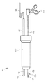
〈処置具〉
図5は、処置具の一例を示す概略構成図である。<Treatment tool>
FIG. 5 is a schematic configuration diagram illustrating an example of a treatment tool.
処置具50は、体腔内に挿入される直棒状の挿入部52(処置具挿入部52)と、処置具挿入部52の先端に配設される処置部54と、処置具挿入部52の後端に配設されるハンドル部(操作部)56とを備えている。図5に示す処置部54は、ハサミ構造とされており、ハンドル部56の開閉操作によって、処置部54が開閉動作される。
The
また、処置具挿入部52には、中心軸に沿った方向の一部の範囲にその前後よりも外径が縮径された縮径部(細径部)58が形成される。縮径部58の作用については後述する。
In addition, the treatment
なお、処置具50は、これに限らず、鉗子、レーザープローブ、縫合器、電気メス、持針器、超音波吸引器等を処置具として使用できる。
The
〈外套管〉
図1に示した外套管100は、患者の体腔壁に穿刺され、その内部に内視鏡10及び処置具50が挿通されて、内視鏡10及び処置具50を患者の体腔内に案内する。<Coat>
The
図6は、外套管100を後方から示した後方斜視図であり、図7は、外套管100を前方から示した前方斜視図である。これらの図及び図1に示すように外套管100は、体腔内への挿入方向(前後方向)となる長手軸100xを中心軸として円柱状に形成されており、体腔壁(体壁)及び体腔内に挿入可能な前側の挿入部110と、挿入部110よりも拡径されて体外に配置される後側のヘッド部112とから形成されている。
FIG. 6 is a rear perspective view showing the
また、ヘッド部112の後端には長手軸100xに直交する円形状の後端面102が形成され、その後端面102には、内視鏡10の挿入部12(内視鏡挿入部12)を外套管100内に挿入する内視鏡挿入口120aと、処置具50の挿入部52(処置具挿入部52)を外套管100内に挿入する処置具挿入口122aとが設けられている。
In addition, a circular
一方、挿入部110の前端には長手軸100xに直交する円形状の前端面104が形成され、その前端面104には、内視鏡挿入口120aから挿入された内視鏡挿入部12を外套管100外に繰り出す内視鏡繰出口120bと、処置具挿入口122aから挿入された処置具挿入部52を外套管100外に繰り出す処置具繰出口122bとが設けられている。
On the other hand, a circular
図8は、外套管100の側面断面図である。同図に示すように、外套管100は、外套管100の略全体を形成するガイド部材としての外套管本体130と、外套管100の後端側(ヘッド部112の後端)に設けられる弁部材132と、外套管100の内部(挿入部110の内部)に設けられる連動機構134等を備えて構成されている。
FIG. 8 is a side sectional view of the
外套管本体130は、外套管100の内部に所要の空間を形成し保持するための外套管100の主部材であり、例えば、ステンレス、アルミニウム等の金属、又は、硬質プラスチック等の剛性を有する素材によって外套管100の内部の非空間部を形成している。なお、外套管本体130は一体形成されたものではなく、複数の部材を接合して構成されたものであってもよい。
The outer tube
外套管本体130の後端には、円柱状の凹部140が形成されており、その凹部140に円柱状の弁部材132が嵌合されて固定されている。これによって、外套管100の後端側に弁部材132が配置される。外套管100の後端面102は、弁部材132とその周囲を囲む外套管本体130の端面によって形成されている。
A
外套管本体130の内部には、図8における9−9矢視断面を示した図9にも示すように、長手軸100xと平行な内視鏡挿通軸120xを中心軸とする内視鏡挿通孔120と、長手軸100x及び内視鏡挿通軸120xと平行な処置具挿通軸122xを中心軸とする処置具挿通孔122とが形成されている。
Inside the outer tube
内視鏡挿通孔120は、外套管100により体腔内に案内する内視鏡挿入部12の外径(直径)よりも僅かに大きい直径を有する断面円形の管腔(管路)を形成している。その前端側は、外套管100の前端面104まで延在して前端面104に上述の内視鏡繰出口120bを形成している。
The
一方、内視鏡挿通孔120の後端側は、外套管本体130の後端面(凹部140の底面)まで形成されている。そして、内視鏡挿通孔120は、外套管本体130から連通して弁部材132に延設され、外套管100の後端面102に上述の内視鏡挿入口120aを形成している。
On the other hand, the rear end side of the
これによって、外套管に100に内視鏡10(内視鏡挿入部12)を進退自在に挿通可能な内視鏡挿通孔120が設けられる。外套管100の後端面102の内視鏡挿入口120aから内視鏡挿入部12を挿入すると、内視鏡挿入部12の中心軸が内視鏡挿通孔120の中心軸である内視鏡挿通軸120xと略重なる位置を通過しながら内視鏡挿通孔120に案内されて、外套管100の前端面104の内視鏡繰出口120bから繰り出される。
Accordingly, an
同様に、処置具挿通孔122は、外套管100により体腔内に案内する処置具挿入部52の外径(直径)よりも僅かに大きい直径を有する断面円形の管腔を形成している。その前端側は、外套管100の前端面104まで延在して前端面104に上述の処置具繰出口122bを形成している。
Similarly, the treatment
一方、処置具挿通孔122の後端側は、外套管本体130の後端面(凹部140の底面)まで形成されている。そして、処置具挿通孔122は、外套管本体130から連通して弁部材132に延設され、外套管100の後端面102に上述の処置具挿入口122aを形成している。
On the other hand, the rear end side of the treatment
これによって、外套管に100に処置具50(処置具挿入部52)を進退自在に挿通可能な処置具挿通孔122が設けられる。外套管100の後端面102の処置具挿入口122aから処置具挿入部52を挿入すると、処置具挿入部52の中心軸が処置具挿通孔122の処置具挿通軸122xと略重なる位置を通過しながら処置具挿通孔に案内されて、外套管100の前端面104の処置具繰出口122bから繰り出される。
Thus, a treatment
なお、図8、図9では、内視鏡挿通孔120と処置具挿通孔122とが略同一の直径であるものとして、また、内視鏡挿通軸120xと処置具挿通軸122xとが長手軸100xに対して略同一距離となる位置に配置されているものとして示されているが、必ずしもこれに限らない。
8 and 9, it is assumed that the
図8において外套管本体130の後端の凹部140に固定された弁部材132は、例えば気腹装置により体腔内に送り込まれた体腔内を膨らませるための気腹ガス(炭酸ガス等)が内視鏡挿通孔120や処置具挿通孔122を通じて体外に漏れ出すのを防ぐために設けられている。
In FIG. 8, the
図10は、図8における弁部材132の周辺部を拡大した拡大図であり、図11は、弁部材132の概略構成を示す分解斜視図である。
FIG. 10 is an enlarged view of the peripheral portion of the
これらの図に示すように弁部材132は、長手軸100xに沿って後端側から前端側に向かって順に、後側保持部材150と、第1の弁体152と、中間部材154と、第2の弁体156と、前側保持部材158とを備えて構成されている。
As shown in these drawings, the
これらの部材150〜158は、同じ外径を有する円形の板状の部材(円盤状の部材)であり、同軸上に重ねて配置されることにより一体化されて弁部材132を構成し、その軸が長手軸100xと重なるように外套管本体130に取り付けられる。
These
後側保持部材150、中間部材154、及び前側保持部材158は、ステンレス、アルミニウム等の金属、又は、硬質プラスチック等の剛性を有する素材で構成され、各々の間に挟み込まれる第1の弁体152と第2の弁体156とを補強する役割を果たす。
The
また、後側保持部材150、中間部材154、及び前側保持部材158には、上述の内視鏡挿通孔120と処置具挿通孔122とを形成する孔120c〜120e、122c〜122e(図11参照)が形成され、孔120c〜120eの中心軸は内視鏡挿通軸120xと重なる位置に配置され、孔122c〜122eの中心軸は処置具挿通軸122xと重なる位置に配置される。なお、後側保持部材150の後面が外套管100の後端面102を形成し、後側保持部材150の孔120c、122cの後端の開口が上述の内視鏡挿入口120aと処置具挿入口122aとを形成している。
Further, the
第1の弁体152と第2の弁体156は、ともに天然ゴム、合成ゴム、シリコーンゴム等の弾性を有する素材により弾性変形可能に形成されている。
Both the
第1の弁体152には、内視鏡用開口型気密弁部152aと、処置具用スリット型気密弁部152b(図11参照)とが形成されている。
The
内視鏡用開口型気密弁部152aは、その内径が内視鏡挿入部12の外径よりも若干小さい円形の開口であり、その開口の中心が内視鏡挿通軸120x上に配置される。したがって、内視鏡挿入部12が内視鏡用開口型気密弁部152aに嵌入されると、その開口の周縁が内視鏡挿入部12の外周面に密着する。これにより、内視鏡挿入部12が内視鏡挿通孔120に挿入されたとき、内視鏡挿入部12と内視鏡挿通孔120との間に形成される隙間がシールされる。
The endoscope opening-type
処置具用スリット型気密弁部152bは、所定長さを有する一本の直線状のスリットとして形成され、そのスリットの中心が処置具挿通軸122x上に配置される。この処置具用スリット型気密弁部152bは、処置具挿入部52が処置具挿通孔122から抜去されているときに、処置具挿通孔122を閉塞する。
The treatment instrument slit type
第2の弁体156には、処置具用開口型気密弁部156aと内視鏡用スリット型気密弁部156b(図11参照)とが形成されている。
The
処置具用開口型気密弁部156aは、その内径が処置具挿入部52の外径よりも若干小さく形成された円形の開口であり、その開口の中心が処置具挿通軸122x上に配置される。したがって、処置具挿入部52が処置具用開口型気密弁部156aに嵌入されると、その開口の周縁が処置具挿入部52の外周面に密着する。これにより、処置具挿入部52が処置具挿通孔122に挿入されたとき、処置具挿入部52と処置具挿通孔122との間に形成される隙間がシールされる。
The treatment instrument opening type
内視鏡用スリット型気密弁部156bは、所定長さを有する一本の直線状のスリットとして形成され、そのスリットの中心が内視鏡挿通軸120x上に配置される。この内視鏡用スリット型気密弁部156bは、内視鏡挿入部12が内視鏡挿通孔120から抜去されているときに、内視鏡挿通孔120を閉塞する。
The endoscopic slit-type
以上のように構成される弁部材132によれば、内視鏡10(内視鏡挿入部12)と処置具50(処置具挿入部52)とが外套管100に挿入されているときは、内視鏡用開口型気密弁部152aと処置具用開口型気密弁部156aとによって、外套管100の気密性が確保される。また、内視鏡挿入部12と処置具挿入部52とが外套管100に挿入されていないときは、内視鏡用スリット型気密弁部156bと処置具用スリット型気密弁部152bとによって、外套管100の気密性が確保される。
According to the
図8において、外套管本体130の前後方向の範囲の中央付近に設けられている連動機構134は、処置具挿通孔122に挿通された処置具挿入部52を術者が進退移動(前後移動)させた際に、これと連動して回転する回転部材を介して、内視鏡挿通孔120に挿通された内視鏡挿入部12を進退移動(前後移動)させるようにした進退移動伝達機構である。構成については後述するが、この連動機構134によれば、処置具50の先端に設けられた処置部54の前後方向の位置に応じて、内視鏡10の撮影画像内における処置部54の位置及び大きさを一定に維持するように内視鏡10の視野範囲(視点の前後方向の位置)が変更される。そのため、処置具50を操作しながら内視鏡10の視野範囲を調整する操作を必ずしも行う必要がなく、スコピストがいなくても、1人の術者が内視鏡10の撮影画像を見ながら処置具50の操作だけを行って施術を行うことができる。
In FIG. 8, the
ここで、図34は、このような連動機構134を備えた外套管100を用いた内視鏡手術装置1の使用形態を示す概略図である。同図に示すように内視鏡10と処置具50とは、患者の体腔壁(体壁)2に穿刺された外套管100を介して体腔3に挿入される。術者が、処置具50を進退移動(前後移動)させると、連動機構134によって内視鏡10が前後移動し、処置具50を傾動させると、外套管100と共に内視鏡10が傾動する。したがって、内視鏡10の視野範囲を処置部54に追従させることができ、常に処置部分(処置部54)の映像がモニタ32に表示される。
Here, FIG. 34 is a schematic view showing a usage pattern of the endoscopic
また、内視鏡10は、照明手段が備えられていないので、照明手段として、ニードルライト40が使用される。ニードルライト40は、ニードルライト用外套管41を介して体腔3に挿入される。体腔3は、ニードルライト40の先端から照射される照明光によって照らされる。なお、本例では1本のニードルライト40を使用する場合を例示したが、必要に応じて複数本のニードルライト40を使用してもよい。また、内視鏡10が照明手段を有しており、ニードルライト40を使用しない場合であってもよい。
Further, since the
このように、本実施の形態の内視鏡手術装置1によれば、処置具50の操作によって内視鏡10も操作されるので、一人の術者で処置を行うことができる。すなわち、スコピストが不要となる。また、外套管100を介して内視鏡10と処置具50とが体腔3に挿入されるため、内視鏡10と処置具50とを体腔に挿入するための穿刺箇所が1カ所で済む。これにより、低侵襲な手術を行うことができる。
Thus, according to the
また、外套管100の連動機構134には、処置具挿入部52の微少な進退移動に対して内視鏡挿入部12が進退移動しない遊びが設けられるようになっている。術者が処置具50の処置部54を操作して処置を施している際などにおいて、意図的又は非意図的に処置具挿入部52(処置部54)に微少な進退移動(前後方向の位置の変動)が生じる場合がある。そのような微少な進退移動に対しても連動機構134によって内視鏡挿入部12が連動すると、内視鏡10の撮影画像(視野範囲)が全体的に動いて施術が行い難くなる。例えば、処置部54が内視鏡10の視野範囲から外れない程度の進退移動であれば、内視鏡10の連動させずに停止させておく方が施術が行い易い場合がある。そのため、連動機構134には遊びが設けられており、内視鏡挿入部12の不要な追従が行われないようになっている。
Further, the
以下において、連動機構134の具体的な形態として第1〜第3の実施の形態を適用した連動機構134について順に説明する。
Hereinafter, the
<第1の実施の形態の連動機構>
まず、第1の実施の形態の連動機構134について説明すると、図8には、第1の実施の形態の連動機構134の構成が示されており、図12は、図8における連動機構134の周辺部を拡大した拡大図、図13は、図12における13−13矢視断面図である。また、図14は、図13の断面を斜めから示した斜視図である。<Interlocking mechanism of the first embodiment>
First, the
これらの図に示すように、外套管本体130の内部には、連動機構134を配置するための空洞部170が形成されている。
As shown in these drawings, a
空洞部170は、内視鏡挿通孔120の内周面120sから処置具挿通孔122の内周面122sまでを貫通するように形成されており、例えば、内視鏡挿通軸120xと処置具挿通軸122xとを対辺とする長方形の平面に対して直交方向の所定距離の範囲に含まれる外套管本体130の隔壁部130aを切り欠いたような形状を有している。
The
ここで、内視鏡挿通軸120x、処置具挿通軸122xとは上述のように平行に配置されており、それらの含む平面を水平基準面(内視鏡挿通軸120xを含み、かつ、処置具挿通軸122xに平行な平面)というものとすると、長手軸100xを前後方向とするのに対して、水平基準面に直交する方向を上下方向とし、水平基準面に水平な方向で、かつ、長手軸100xと直交する方向を左右方向とする。なお、本実施の形態では、長手軸100xも水平基準面と同一平面上に配置されているが、水平基準面と長手軸100xとの関係はこれに限らない。
Here, the
一方、第1の実施の形態の連動機構134は、図12〜図14に示すように、空洞部170において左右方向に並べて配置された内視鏡側ローラ200(内視鏡側回転部材)と処置具側ローラ202(処置具側回転部材)とを備え、内視鏡側ローラ200は、内視鏡挿通孔120側に配置され、処置具側ローラ202は、処置具挿通孔122側に配置されている。
On the other hand, as shown in FIGS. 12 to 14, the
これらの内視鏡側ローラ200と処置具側ローラ202とは、同一径の円筒面(外周面200s、202s)を有する円柱状部材であり、それらの中心軸(回転軸)が水平基準面と直交するように配置される。即ち、内視鏡側ローラ200と処置具側ローラ202の各々の中心軸が内視鏡挿通軸120xと処置具挿通軸122xの両方に平行な平面に直交する方向に配置されている。
The
内視鏡側ローラ200と処置具側ローラ202の上下両側の端面の各々には、内視鏡側ローラ200と処置具側ローラ202(外周面200s、202s)の中心軸(回転軸)に沿って延びる軸ピン200a、200b、202a、202bが設けられている(図13、図14参照)。
The end surfaces on both the upper and lower sides of the
一方、空洞部170内の上下の壁面には、対向位置に配置された一対の係合穴172a、172bと、一対の係合穴174a、174bとが形成されている(図13参照)。そして、内視鏡側ローラ200の軸ピン200a、200bが、各々、係合穴172a、172bに嵌入され、処置具側ローラ202の軸ピン202a、202bが、各々、係合穴174a、174bに嵌入されている。
On the other hand, a pair of engagement holes 172a and 172b and a pair of engagement holes 174a and 174b arranged at opposite positions are formed on the upper and lower wall surfaces in the cavity 170 (see FIG. 13). The shaft pins 200a and 200b of the
これによって、空洞部170内において、内視鏡側ローラ200が軸ピン200a、200bを介してその中心軸周りに回動可能に支持され、処置具側ローラ202が軸ピン202a、202bを介してその中心軸周りに回動可能に支持されている。
As a result, the
なお、内視鏡側ローラ200と処置具側ローラ202を空洞部170に回動可能に支持する手段はどのような形態であってもよい。
Note that the means for rotatably supporting the
また、内視鏡側ローラ200と処置具側ローラ202は、回転可能に支持されている形態であれば、上記のように軸ピンと共に回転する形態でなくてもよい。例えば、内視鏡側ローラ200と処置具側ローラ202の中心軸の位置を挿通する軸部材の周りに回動可能に支持されていてもよい。
In addition, the
更に、外套管本体130の内部に空洞部170を形成するため、また、空洞部170内に内視鏡側ローラ200及び処置具側ローラ202を設置するために、外套管本体130の一部の領域の部材を残りの領域の部材から分離可能な別体の部材として構成すればよい。たとえば、図8は外套管本体130を水平基準面で切断した断面として示されているが、外套管本体13を水平基準面で上下の2つの領域に分離された2つの部材で構成する形態としてもよい。その場合に、各々の部材に空洞部170を形成する凹部を形成し、一方の凹部に内視鏡側ローラ200及び処置具側ローラ202を配置してから、それらの2つの部材の水平基準面となる面同士を当接させて固定すればよい。
Further, in order to form the
また、外套管本体130の局所的な領域のみを残りの領域から分離可能な部材として構成してもよい。この場合、外套管本体130の外部から空洞部170内に内視鏡側ローラ200及び処置具側ローラ202を挿入、設置する通路を設け、空洞部170内に内視鏡側ローラ200及び処置具側ローラ202を設置した後に、その通路を塞ぐように分離された部材を固定するようにしてもよい。
Moreover, you may comprise as a member which can isolate | separate only the local area | region of the outer tube | pipe
分離された複数の部材を固定する手段は、接着剤による接着や、ネジ止め等の任意の手段を用いることができる。 As a means for fixing the plurality of separated members, any means such as adhesion with an adhesive or screwing can be used.
このようにして空洞部170に配置された内視鏡側ローラ200と処置具側ローラ202とは、それらの外周面200sと外周面202sとが互いに接触する位置に配置されている。これによって、内視鏡側ローラ200と処置具側ローラ202とが摩擦力により連結され、一方のローラの回転によって他方のローラが連動して回転するようになっている。このとき、内視鏡側ローラ200と処置具側ローラ202とは反対方向に回転する。
Thus, the
また、内視鏡側ローラ200は、その外周面200sの周方向の一部の範囲が内視鏡挿通孔120の内周面120sに沿う面位置よりも内視鏡挿通孔120内に突出するように配置されている。これによって、図15に示すように内視鏡挿通孔120に挿通された内視鏡挿入部12の外周面12sに内視鏡側ローラ200の外周面200sが接触して連結されるようになっている。図15は、図12の拡大図において内視鏡挿通孔120及び処置具挿通孔122の各々に内視鏡挿入部12及び処置具挿入部52が挿通された状態を示す。
Further, the
したがって、内視鏡側ローラ200の回転と連動して内視鏡挿入部12が進退移動(前後移動)し、また、内視鏡挿入部12の進退移動と連動して内視鏡側ローラ200が回転する。
Therefore, the
なお、内視鏡側ローラ200の外周面200sから内視鏡挿入部12の外周面12sが離間しないようにすることが望ましい。そのために、内視鏡挿通孔120の直径、内視鏡挿通軸120xの位置、又は、内視鏡側ローラ200の外周面200sの内視鏡挿通孔120への突出量等の設計条件によって、内視鏡挿入部12の外周面12sと内視鏡挿通孔120の内視鏡側ローラ200に対向する位置の内周面120sとの間に隙間が生じないようにすることができる。また、図19のように例えば、内視鏡挿通孔120の内周面120sの内視鏡側ローラ200に対向する位置又はその周辺部等、内視鏡挿通孔120の内周面120sのいずれかの位置に、内視鏡挿入部12が内視鏡側ローラ200から離間するのを防止する突起210や、内視鏡挿入部12を内視鏡側ローラ200に当接する方向に付勢する板バネのような付勢部材212を設けてもよい。
It is desirable that the outer
一方、処置具側ローラ202は、その外周面202sの周方向の一部の範囲が処置具挿通孔122の内周面122sに沿う面位置よりも処置具挿通孔122内に突出するように配置されている。これによって、図15に示すように、処置具挿通孔122に挿通された処置具挿入部52の外周面52s(縮径部58の範囲を除く非縮径部の外周面52s)に処置具側ローラ202の外周面202sが接触するようになっている。
On the other hand, the treatment
したがって、処置具挿入部52の進退移動と連動して処置具側ローラ202が回転し、また、処置具側ローラ202の回転と連動して処置具挿入部52が進退移動するようになっている。
Accordingly, the treatment
なお、処置具側ローラ202の外周面202sから処置具挿入部52の外周面52sが離間しないようにすることが望ましい。そのために、処置具挿通孔122の直径、処置具挿通軸122xの位置、又は、処置具側ローラ202の外周面202sの処置具挿通孔122への突出量等の設計条件によって、処置具挿入部52の外周面52sと処置具挿通孔122の処置具側ローラ202に対向する位置の内周面122sとの間に隙間が生じないようにすることができる。また、図19に示した内視鏡挿通孔120の突起210や付勢部材212と同様のものを、例えば、処置具挿通孔122の内周面122sの処置具側ローラ202に対向する位置又はその周辺部等、処置具挿通孔122の内周面122sのいずれかの位置に設けてもよい。
It is desirable that the outer
また、内視鏡側ローラ200と処置具側ローラ202とは、全体が単にプラスチック(合成樹脂)等により一体形成されたものであってもよいし、それらの外周面200s、202sと接触物との間のすべりを軽減するために、外周面200s、202sにゴム材料等の摩擦係数の大きい材料でコーティングを施したものや外周面200s、202sに滑り止め用の細かい凹凸を形成したものであってもよい。
Further, the
また、内視鏡側ローラ200、処置具側ローラ202の外周部に、摩擦係数の大きい材料で形成された帯状部材を巻回して外周面200s、202sを形成(摩擦係数の大きいリング状部材を外周部に嵌合したもの)したものでもよいし、内視鏡側ローラ200と処置具側ローラ202の全体を摩擦係数の大きい材料で形成したものでもよい。
Further, a belt-like member made of a material having a large friction coefficient is wound around the outer peripheral portions of the
さらに、内視鏡側ローラ200と処置具側ローラ202の外周面に歯車(ギヤ)を形成して歯車とし、それらを噛合させることによって内視鏡側ローラ200と処置具側ローラ202とを連動させるようにしてもよい。
Furthermore, gears (gears) are formed on the outer peripheral surfaces of the
また、処置具側ローラ202の上下いずれかの端面(円板状の回転部材の板面)と処置具挿入部52の外周面52sとを接触させて、処置具挿入部52の進退移動に対して処置具側ローラ202を回転させるようにしてもよい。内視鏡側ローラ200と内視鏡挿入部12との連動も同様である。
Further, either the upper or lower end face of the treatment instrument side roller 202 (the plate surface of the disk-shaped rotating member) and the outer
以上のように構成された第1の実施の形態の連動機構134によれば、外套管100の処置具挿通孔122に挿通された処置具挿入部52を進退移動させると、これと連動して、連動機構134の処置具側ローラ202が回転する。例えば、処置具挿入部52を前進させた場合には、処置具側ローラ202の外周面202sと処置具挿入部52の外周面52sとの接触位置において外周面202sが前向きに移動するような回転方向(図15において時計回り方向)に処置具側ローラ202が回転する。
According to the
処置具側ローラ202が回転すると、これと連動して、内視鏡側ローラ200が処置具側ローラ202と反対方向に回転する。例えば、処置具挿入部52を前進させた場合には、内視鏡側ローラ200の外周面200sと処置具側ローラ202の外周面202sとの接触位置において外周面200sが後向きに移動するような回転方向(図15において反時計回り方向)に内視鏡側ローラ200が回転する。
When the treatment
そして、内視鏡側ローラ200が回転すると、これと連動して、内視鏡挿通孔120に挿通された内視鏡挿入部12が進退移動する。例えば、処置具挿入部52を前進させた場合には、内視鏡挿入部12の外周面12sと内視鏡側ローラ200の外周面200sとの接触位置において外周面12sが前向きに移動するように内視鏡挿入部12が前進する。
Then, when the
このようにして、処置具挿入部52の進退移動と連動して内視鏡挿入部12も進退移動し、処置具挿入部52を前進させた場合には、その移動量と同じ移動量分だけ内視鏡挿入部12も前進し、処置具挿入部52を後退させた場合には、その移動量と同じ移動量分だけ内視鏡挿入部12も後退する。なお、術者が内視鏡挿入部12を進退移動させた場合も同様にこれと連動して処置具挿入部52が進退移動する。
In this way, when the
ところで、図5に示したように処置具挿入部52には、中心軸に沿った前後方向の一部の範囲にその前後よりも外径が縮径された縮径部(細径部)58が形成される。なお、処置具挿入部52の縮径部58以外の範囲を非縮径部(太径部)というものとすると、非縮径部の外径(第1の外径)よりも縮径部58の外径(第2の外径)は小さい。
Incidentally, as shown in FIG. 5, the treatment
図8の側面断面図において内視鏡挿通孔120及び処置具挿通孔122の各々に内視鏡挿入部12及び処置具挿入部52を挿通させた状態を示した図16の側面断面図に示すように、処置具挿入部52の縮径部58は、処置具挿入部52を外套管100の処置具繰出口122bから所定量繰り出した状態において、処置具側ローラ202に対向する位置に配置されるようになっている。
In the side sectional view of FIG. 8, the
このとき、処置具側ローラ202の外周面202sと処置具挿入部52の外周面52sとは接触しないため、処置具挿入部52の進退移動に対して処置具側ローラ202が回転せず、内視鏡挿入部12が連動して進退移動しないようになっている。即ち、処置具挿入部52の進退移動に対して内視鏡挿入部12が進退移動しない(連動しない)遊びを設けるための縮径部58が連動機構134の構成要素として処置具挿入部52に設けられる。
At this time, since the outer
たとえば、処置具挿入部52の前後方向の縮径部58の長さをLとし、その中央点が処置具側ローラ202の中心軸に対して左右方向に対向する位置(前後方向の同一位置)に配置されている状態であるとすると、処置具挿入部52をその状態の位置から前後にL/2以下の移動量となる範囲で移動させている間は、処置具挿入部52の外周面52sに処置具側ローラ202の外周面202sに接触しない。したがって、その移動量の範囲では内視鏡挿入部12は連動せず、連動機構134の遊びの範囲となる。
For example, the length of the diameter-reduced
図17、図18は、その連動機構134の遊びの範囲を説明した図である。
FIGS. 17 and 18 are diagrams illustrating the range of play of the
図17の(A)部は、上記のように処置具挿入部52の縮径部58の中央点が処置具側ローラ202の中心軸に対して前後方向の同一位置に配置されている状態を示しており、外套管100の前端面104(処置具繰出口122b)からの処置部54の繰出量がMとなっている。
17A shows a state in which the central point of the reduced
内視鏡挿通孔120に挿通された内視鏡10の先端の外套管100の前端面104(内視鏡繰出口120b)からの繰出量は、術者が望む視野範囲の画像が得られるように調整されており、適宜調整可能である(詳細は後述する)。
The amount of feeding from the front end surface 104 (
この状態から処置具挿入部52をL/2の移動量となる位置まで前進させ、処置部54を移動量L/2だけ前進させると、その間では、処置具挿入部52の外周面52sが処置具側ローラ202の外周面202sに接触しない。そのため、連動機構134の処置具側ローラ202が回転せず、図17の(B)部に示すように、内視鏡挿入部12の先端の位置は変化しない。また、処置具挿入部52をL/2の移動量となる位置まで前進させた時点で、処置具挿入部52の縮径部58の後端、即ち、縮径部58よりも後側の非縮径部の前端が処置具側ローラ202の外周面202sに接触する。
From this state, when the treatment
続いて処置具挿入部52を前進させて処置部54を前進させると、即ち、L/2の移動量となる位置よりも更に処置部54を前進させると、処置具挿入部52の非縮径部の外周面52sが処置具側ローラ202の外周面202sに接触して処置具側ローラ202が図中時計回り方向に回転する。
Subsequently, when the treatment
これによって、内視鏡側ローラ200が図中反時計回り方向に回転し、図17の(C)部に示すように処置具挿入部52の前進と連動して内視鏡挿入部12が前進する。このとき、処置具挿入部52を前進させた移動量をxとすると、内視鏡挿入部12の先端も移動量xだけ前進する。
As a result, the endoscope-
処置具挿入部52を後退させた場合もこれと同様の動作となる。図18の(A)部は、図17の(A)部と同様に処置具挿入部52の縮径部58の中央点が処置具側ローラ202の中心軸に対して前後方向の同一位置に配置されている状態を示している。この状態から処置具挿入部52をL/2の移動量となる位置まで後退させ、処置部54を移動量L/2だけ後退させると、その間では、処置具挿入部52の外周面52sが処置具側ローラ202の外周面202sに接触しない。そのため、連動機構134の処置具側ローラ202が回転せず、図18の(B)部に示すように、内視鏡挿入部12の先端の位置は変化しない。また、処置具挿入部52をL/2の移動量となる位置まで後退させた時点で、処置具挿入部52の縮径部58の前端、即ち、縮径部58よりも前側の非縮径部の後端が処置具側ローラ202の外周面202sに接触する。
The same operation is performed when the treatment
続いて処置具挿入部52を後退させて処置部54を後退させると、即ち、L/2の移動量となる位置よりも更に処置部54を後退させると、処置具挿入部52の非縮径部の外周面52sが処置具側ローラ202の外周面202sに接触して処置具側ローラ202が図中反時計回り方向に回転する。
Subsequently, when the treatment
これによって、内視鏡側ローラ200が図中時計回り方向に回転し、図18の(C)部に示すように処置具挿入部52の後退と連動して内視鏡挿入部12が後退する。このとき、処置具挿入部52を後退させた移動量をxとすると、内視鏡挿入部12の先端も移動量xだけ後退する。
As a result, the
以上のように処置具挿入部52の進退移動に対する連動機構134の遊びを設けることによって、例えば、術者が処置具50の処置部54を操作して処置を施している際などにおいて、意図的又は非意図的に処置具挿入部52に少量の進退移動(進退位置の変動)が生じた場合であっても、内視鏡10の視野範囲が変動せず、施術を行い易い撮影画像が得られる。
By providing play of the
なお、このような遊びの大きさは、処置具挿入部52の縮径部58の長さLによって変更可能である。
In addition, the magnitude | size of such a play can be changed with the length L of the
また、遊びは、外套管100(処置具繰出口122b)から処置具挿入部52の処置部54を一定の繰出量Mで繰り出している状態に限られているが、術者が遊びを設けることを望む体腔内への処置部54の挿入位置において、そのような繰出量Mとなるように、外套管100の体腔内(体腔壁)への挿入量を調整すればよい。または、同種の処置具50に関して、処置部54から処置具挿入部52の縮径部58までの距離(縮径部58の位置)が異なるものを複数用意しておき、それらの中から、遊びを有するときの処置部54の繰出量Mが最適となるものを選択して使用するようにしてもよい(遊びの大きさを変更する場合の縮径部58の長さLについても同様に選択可能にすることができる)。
In addition, play is limited to a state where the
また、上述のように処置具50が遊びを有するときの内視鏡10の先端の繰出量は、術者が適宜調整することができる。たとえば、内視鏡挿入部12を処置具挿入部52と同時に外套管100に挿入する場合、又は、処置具挿入部52を先に外套管100に挿通させる場合には、処置具50が遊びを有する状態となったとき、即ち、内視鏡挿入部12が処置具挿入部52と連動しない状態となったときに、内視鏡挿入部12のみを内視鏡挿通孔120内で進退移動させて内視鏡挿入部12の先端を所望の繰出量に調整することができる。一方、内視鏡挿入部12を先に外套管100に挿通させる場合には、内視鏡挿入部12を所望の繰出量に調整した後、処置具挿入部52を処置具挿通孔122に挿通させる際に、処置具挿入部52が遊びを有する状態となるまで、内視鏡挿入部12の後端側を手で把持するなどして、処置具挿入部52と連動して内視鏡挿入部12が進退移動しないようにすればよい。
In addition, the operator can appropriately adjust the amount of extension of the distal end of the
<第1の実施の形態の連動機構の変形例>
上記の第1の実施の形態の連動機構134では、処置具挿入部52に縮径部58を形成することによって、処置具側ローラ202の外周面202sに接触しない範囲を設ける。これにより、処置具50(処置具挿入部52)と処置具側ローラ202とを非連動にする非連動部を設けるようにしている。しかしながら、非連動部の構成はこれに限らない。例えば、処置具挿入部52に非連動部として縮径部58を形成する代わりに、縮径部58に相当する範囲の外周面をその前後の範囲(非縮径部に相当する範囲)よりも滑り易い材質で形成し、縮径部58に相当する範囲では、処置具挿入部52を進退移動させても処置具側ローラ202が回転しないようにしてもよい。<Modification of interlocking mechanism of the first embodiment>
In the
また、処置具挿入部52に縮径部58のように、処置具50と処置具側ローラ202とを非連動にする非連動部を設けるのではなく、処置具挿入部52を円筒状のパイプ状部材の中空部に進退自在に挿通させ、そのパイプ状部材と共に処置具挿入部52を処置具挿通孔122に挿入するようにして遊びを設けるようにしてもよい。
In addition, the treatment
図20は、そのようなパイプ状部材により遊びを設けるようにした場合の形態を第1の実施の形態の連動機構134の変形例として示した外套管100の側面断面図である。なお、同図において、図8、図16等に示した第1の実施の形態の連動機構134を備えた外套管100の構成要素と同一又は類似作用の構成要素には同一符号を付して説明を省略する。
FIG. 20 is a side cross-sectional view of the
図20に示すように、処置具挿通孔122には処置具挿入部52が挿通して配置されるとともに円筒状のパイプ状部材250が配置されている。
As shown in FIG. 20, a treatment
パイプ状部材250は、長筒状に形成されており、その外径が処置具挿通孔122の内径と略一致している。したがって、パイプ状部材250の外周面250sが処置具側ローラ202の外周面202sに接触しており、パイプ状部材250が前後方向に移動すると、これと連動して処置具側ローラ202が回転するようになっている。なお、同図では、図16と比較してパイプ状部材250を配置する分、処置具挿入部52の外径が小さくなっているが、必ずしも処置具挿入部52の外径を小さくする必要はなく、処置具挿通孔122の内径を大きくしてもよい。
The pipe-shaped
一方、パイプ状部材250には、その中心軸に沿って貫通孔252が貫通形成されており、その貫通孔252に処置具挿入部52が挿通されている。
On the other hand, a through-
貫通孔252の内径は、処置具挿入部52の外径よりも僅かに大きく、処置具挿入部52は、パイプ状部材250に対して進退移動可能に挿入されている。
The inner diameter of the through
また、処置具挿入部52には、図5に示したような縮径部58が設けられておらず、パイプ状部材250が外嵌される領域よりも前側と後側にパイプ状部材250と係合する前側係合部254Aと、後側係合部254Bが形成されている。
Further, the treatment
前側係合部254Aと後側係合部254Bとは、例えば、処置具挿入部52の外周面52sに対して径方向に突出しており、周方向に沿って全周に渡って、又は、周方向の一部の範囲に形成されている。
The
そして、これらの前側係合部254Aと後側係合部254Bとは、それらの前後方向の間隔がパイプ状部材250の前後方向の長さよりも広くなる位置に形成されている。これにより、パイプ状部材250は、係合部254Aと254Bとの間で前後方向に移動可能になっている。
And these front
したがって、パイプ状部材250は、処置具挿入部52に対して遊びを持って外嵌されている。
Therefore, the pipe-shaped
なお、パイプ状部材250に前端から後端まで連続する前後方向の切込みを形成し、処置具挿入部52の前側係合部254Aと後側係合部254Bとの間を、その切込みを介してパイプ状部材250の貫通孔252に挿入することによって、処置具挿入部52にパイプ状部材250を外嵌させるようにしてもよいし、他の方法で外嵌させるようにしてもよい。
In addition, a notch in the front-rear direction that is continuous from the front end to the rear end is formed in the pipe-shaped
このようなパイプ状部材250によれば、処置具挿入部52を前進させた場合に、パイプ状部材250の後端に処置具挿入部52の後側係合部254Bが当接するまではパイプ状部材250が進退移動せず、処置具側ローラ202も回転しない。即ち、内視鏡挿通孔120に挿通された内視鏡挿入部12が処置具挿入部52の進退移動に対して連動しない遊びが存在する。
According to such a pipe-shaped
一方、パイプ状部材250の後端に処置具挿入部52の後側係合部254Bが当接した後、更に、処置具挿入部52を前進させると、処置具挿入部52と共にパイプ状部材250が前進し、これと連動して処置具側ローラ202が回転する。したがって、処置具挿入部52と連動して内視鏡挿入部12も前進する。
On the other hand, when the treatment
処置具挿入部52を後退させた場合も同様に、パイプ状部材250の前端に処置具挿入部52の前側係合部254Aが当接するまではパイプ状部材250が進退移動せず、処置具側ローラ202も回転しない。即ち、内視鏡挿入部12が処置具挿入部52の進退移動に対して連動しない遊びが存在する。
Similarly, when the treatment
一方、パイプ状部材250の前端に処置具挿入部52の前側係合部254Aが当接した後、更に、処置具挿入部52を後退させると、処置具挿入部52と共にパイプ状部材250が後退し、これと連動して処置具側ローラ202が回転する。したがって、処置具挿入部52と連動して内視鏡挿入部12も後退する。
On the other hand, after the front
以上のパイプ状部材250のような遊び発生部材を介して処置具挿入部52(処置具50)の進退移動を、内視鏡挿入部12(内視鏡10)に伝達するように構成することで、処置具挿入部52の進退移動に対して内視鏡挿入部12が連動しない連動機構134の遊びを設けることができる。
The advance / retreat movement of the treatment instrument insertion section 52 (treatment instrument 50) is transmitted to the endoscope insertion section 12 (endoscope 10) via a play generating member such as the pipe-shaped
なお、前側係合部254Aと後側係合部254Bとを処置具挿入部52に対して着脱可能な部材として、その装着位置を自由に変更できるようにして遊びの大きさ等を調整できるようにしてもよい。
It should be noted that the
また、パイプ状部材250を処置具挿入部52に遊びをもって外嵌するための構成は、任意の構成を採用することができる。
Moreover, the structure for externally fitting the pipe-shaped
例えば、処置具挿入部52の中心軸に沿った前後方向の一部の領域であって、パイプ状部材250よりも前後方向に長い領域を、その前後よりも縮径化し、その縮径化した領域内にパイプ状部材250を進退移動可能に外嵌させるようにしてもよい。この場合に、パイプ状部材250の外径を処置具挿入部52の縮径化した領域以外の外径と略一致するように形成することで、処置具挿通孔122の内径をパイプ状部材250の外径に合わせて拡径することを不要にすることができる。
For example, a partial region in the front-rear direction along the central axis of the treatment
また、遊び発生部材は、処置具挿通孔122に配置するのではなく、内視鏡挿通孔120に配置してもよく、その場合の構成を図21に示す。同図では、図20と同一又は類似作用の構成要素に同一符号を付しており、パイプ状部材250は、内視鏡挿通孔120に挿通された内視鏡挿入部12に進退移動可能に外嵌され、内視鏡挿入部12には、パイプ状部材250と係合する前側係合部254Aと後側係合部254Bとが設けられている。
Further, the play generating member may be disposed in the
これによれば、処置具挿入部52を前進させた場合に、これと連動して処置具側ローラ202が回転して内視鏡側ローラ200が回転し、パイプ状部材250が前進する。そして、パイプ状部材250の前端が、内視鏡挿入部12の前側係合部254Aに当接するまでは内視鏡挿入部12が進退移動しない。即ち、内視鏡挿入部12が処置具挿入部52の進退移動に対して連動しない遊びが存在する。
According to this, when the treatment
一方、パイプ状部材250の前端が、内視鏡挿入部12の前側係合部254Aに当接した後、更に、処置具挿入部52を前進させると、パイプ状部材250と共に内視鏡挿入部12が前進する。したがって、処置具挿入部52と連動して内視鏡挿入部12も前進する。
On the other hand, after the front end of the pipe-shaped
処置具挿入部52を後退させた場合も同様に、これと連動してパイプ状部材250が後退する。そして、パイプ状部材250の後端が、内視鏡挿入部12の後側係合部254Bに当接するまでは内視鏡挿入部12が進退移動しない。即ち、内視鏡挿入部12が処置具挿入部52の進退移動に対して連動しない遊びが存在する。
Similarly, when the treatment
一方、パイプ状部材250の後端が、内視鏡挿入部12の後側係合部254Bに当接した後、更に、処置具挿入部52を後退させると、パイプ状部材250と共に内視鏡挿入部12が後退する。したがって、処置具挿入部52と連動して内視鏡挿入部12も後退する。
On the other hand, after the rear end of the pipe-shaped
以上の処置具挿入部52の縮径部58の代りにパイプ状部材250のような遊び発生部材を用いて連動機構134の遊びを設けることは、次に説明する第1の実施の形態の連動機構134の変形例や第2の実施の形態の連動機構134に対しても同様に適用できる。
Providing the play of the
また、第1の実施の形態の連動機構134では、内視鏡側ローラ200と処置具側ローラ202が、外套管100の長手軸100xに沿った方向(前後方向)に関して同一となる位置に左右方向に並べて配置されている形態を示したが、必ずしも、内視鏡側ローラ200と処置具側ローラ202が、外套管100の前後方向の同一位置に配置されていなくてもよい。
Further, in the
図22は、その場合の形態を第1の実施の形態の連動機構134の変形例として示した外套管100の側面断面図である。同図において図8、図16等に示した第1の実施の形態の連動機構134を備えた外套管100の構成要素と同一又は類似作用の構成要素には同一符号を付して説明を省略する。
FIG. 22 is a side cross-sectional view of the
図22に示すように、外套管100の空洞部170において、内視鏡側ローラ200は、処置具側ローラ202よりも前側に配置され、内視鏡側ローラ200の中心と処置具側ローラ202の中心とを結ぶ線分上において、内視鏡側ローラ200の外周面200sと処置具側ローラ202の外周面202sとが接触している。これによって、内視鏡側ローラ200と処置具側ローラ202が連動して回転するようになっている。
As shown in FIG. 22, the
また、内視鏡側ローラ200は、外周面200sの周方向の一部の範囲が内視鏡挿通孔120内に突出し、内視鏡挿通孔120に挿通された内視鏡挿入部12の外周面12sに接触するように配置されている。
The endoscope-
処置具側ローラ202は、外周面202sの周方向の一部の範囲が処置具挿通孔122内に突出し、処置具挿通孔122に挿通された処置具挿入部52の非縮径部の外周面52sに接触するように配置されている。
The treatment
これによって、第1の実施の形態と同様に処置具挿入部52の進退移動と連動して内視鏡挿入部12が進退移動すると共に、処置具挿入部52の縮径部58が処置具側ローラ202に対向している状態ではそれらが連動しない連動機構134の遊びが設けられるようになっている。
As a result, as in the first embodiment, the
この変形例によれば、外套管100(挿入部110)の細径化を図ることができる。即ち、図8、図16等のような第1の実施の形態の連動機構134を備えた外套管100と、図22のような変形例の連動機構134を備えた外套管100とを、内視鏡側ローラ200、処置具側ローラ202が同一のもの(外周面の直径が一致したもの)として比較した場合に、図22の変形例の連動機構134を備えた外套管100の方が、内視鏡挿通軸120xと処置具挿通軸122xとを互いに近づけることができるため、その分、外套管本体130(外套管100の挿入部110)の外径を小さくすることができる。
According to this modification, the diameter of the outer tube 100 (insertion portion 110) can be reduced. That is, the
なお、内視鏡側ローラ200を処置具側ローラ202よりも後側に配置してもよい。
Note that the
以上、上述の第1の実施の形態(変形例も含む)の連動機構134は、内視鏡挿通軸120xと処置具挿通軸122xの両方に直交する回転軸(内視鏡挿通軸120xと処置具挿通軸122xの両方に平行な平面に直交する方向の回転軸)を有し、かつ、連動して反対方向に回転する2つのローラの各々を、内視鏡挿入部12と処置具挿入部52の各々に接触(又は遊び発生部材を介して連結)させた形態であるが、連動機構134の構成はこれに限らない。
As described above, the
たとえば、必ずしも2つのローラの回転軸が内視鏡挿通軸120xと処置具挿通軸122xの両方に直交していなくてもよく、立体的に交差していてもよい。また、2つのローラはそれらの外周面を直接接触させて連動させるのではなく、ギヤやベルト、又は、他のローラなどからなる動力伝達機構を介して連動させることも可能である。さらに、動力伝達機構を介して2つのローラを連動させる形態の場合には、2つのローラをどのような位置に配置してもよく、また、回転軸の方向も特定の方向に限定されない。
For example, the rotational axes of the two rollers do not necessarily have to be orthogonal to both the
なお、以下において説明する第2、第3の実施の形態の連動機構134においても以上の第1の実施の形態の連動機構134に関して適用可能な変形的、付加的な構成を適宜採用できる。
In addition, in the
<第2の実施の形態の連動機構>
次に、第2の実施の形態の連動機構134について説明する。<Interlocking mechanism of the second embodiment>
Next, the
第2の実施の形態の連動機構134は、内視鏡挿通軸120xと処置具挿通軸122xの両方に直交する回転軸を有する1つのローラ(1つの回転軸の周りを回転するローラ)を内視鏡挿入部12と処置具挿入部52の両方に接触(又は遊び発生部材を介して連結)させた形態である。即ち、内視鏡挿入部12の外周面12sと処置具挿入部52の外周面52sに同じ方向から接する平面に対して平行な回転軸を有するローラによって処置具50の進退移動に対して内視鏡10を連動させるようにした形態である。
The
図23及び図24は各々、第2の実施の形態の連動機構134を備えた外套管100を側面側と後面側から示した概略図である。なお、連動機構134の構成以外は図8等に示した第1の実施の形態の連動機構134を備えた外套管100と同様に構成されているため、図8等に示した外套管100と同一又は類似作用の構成要素を同一符号を用いて示すものとしてその説明を省略し、第2の実施の形態の連動機構134の特徴的な構成部分のみを説明する。また、図23、図24では、内視鏡挿通孔120よりも処置具挿通孔122の直径の方が小さいものとして示されている。
23 and 24 are schematic views showing the
これらの図に示すように、第2の実施の形態の連動機構134は、外套管100(外套管本体130)の内部に形成された空洞部170に配置された1つのローラ300を備えている。
As shown in these drawings, the
ローラ300は、円筒面(外周面300s)を有する円柱状部材であり、その中心軸(回転軸)は、内視鏡挿通軸120xと処置具挿通軸122xの両方に直交する方向であって、内視鏡挿通孔120の内周面120sと処置具挿通孔122の内周面122sとに接する平面に平行な方向に配置されている。
The
ローラ300の両側の端面の各々には、中心軸に沿って延びる軸ピン300a、300bが設けられている。それらの軸ピン300a、300bが空洞部170の壁面に設けられた不図示の一対の係合穴に嵌入されてローラ300がその中心軸周りに回動可能に支持されている。なお、ローラ300は、ローラ300の中心軸の位置を挿通する軸部材の周りに回動可能に支持されていてもよい。
Axis pins 300a and 300b extending along the central axis are provided on both end faces of the
また、ローラ300は、その中心軸方向の一方の端部側の一部の範囲が内視鏡挿通孔120内に突出し、他方の端部側の一部の範囲が処置具挿通孔122内に突出するように配置されている。これによって、内視鏡挿通孔120に挿通された内視鏡挿入部12の外周面12sと、処置具挿通孔122に挿通された処置具挿入部52の外周面52s(縮径部58の範囲を除く)にローラ300の外周面300sが接触するようになっている。
In addition, the
したがって、処置具挿入部52の進退移動によってローラ300が回転し、そのローラ300の回転と連動して内視鏡挿入部12が進退移動する。また、処置具挿入部52の縮径部58がローラ300の外周面300sに対向するときには、処置具挿入部52の外周面52sがローラ300の外周面300sに接触しないため、処置具挿入部52の進退移動に対して連動機構134の遊びが設けられる。
Accordingly, the
なお、図20、図21に示したような遊び発生部材(パイプ状部材250)によって連動機構134の遊びを設けるようにしてもよい。
In addition, you may make it provide the play of the
<第3の実施の形態の連動機構>
次に、第3の実施の形態の連動機構134について説明する。<Interlocking mechanism of the third embodiment>
Next, the
第1及び第2の実施の形態の連動機構134では、処置具挿入部52に縮径部58のような加工を施すことにより、または、図20、図21のパイプ状部材250のように処置具挿通孔122や内視鏡挿通孔120に配置される遊び発生部材により、処置具挿入部52の進退移動に対する連動機構134の遊びを設けるようにした。一方、第3の実施の形態の連動機構134では、処置具挿入部52に加工を施すことなく、また、処置具挿通孔122や内視鏡挿通孔120に配置される遊び発生部材を用いることなく、連動機構134の遊びを設けるようにした形態である。
In the
図25は、第3の実施の形態の連動機構134を備えた外套管100を側面側から示した概略図である。なお、連動機構134の構成以外は図8等に示した第1の実施の形態の連動機構134を備えた外套管100と同様に構成されているため、図8等に示した外套管100と同一又は類似作用の構成要素を同一符号を用いて示すものとしてその説明を省略し、第3の実施の形態の連動機構134の特徴的な構成部分のみを説明する。
FIG. 25 is a schematic view showing the
同図に示すように、第3の実施の形態の連動機構134は、外套管本体130内に第1の実施の形態と同様の位置に形成された空洞部170に配置された2つの内視鏡側ローラ200−1、200−2と処置具側ローラ202とを備えている。内視鏡側ローラ200−1と内視鏡側ローラ200−2とは、長手軸100xに沿った前後方向の2箇所の位置に所定間隔をあけて配置されている。
As shown in the figure, the
内視鏡側ローラ200−1、200−2と処置具側ローラ202は、円筒面(外周面200s−1、200s−2、202s)を有する円柱状部材であり、それらの中心軸(回転軸)が、第1の実施の形態と同様に、水平基準面(内視鏡挿通軸120xを含み、かつ、処置具挿通軸122xに平行な平面)と直交するように配置される。即ち、内視鏡側ローラ200−1、200−2と処置具側ローラ202の各々の中心軸が内視鏡挿通軸120xと処置具挿通軸122xの両方に直交する方向に配置されている。
The endoscope side rollers 200-1 and 200-2 and the treatment
内視鏡側ローラ200−1、200−2の上下両側の端面の各々には、第1の実施の形態と内視鏡側ローラ200と同様に、それらの中心軸に沿って軸ピンが設けられており、空洞部170の壁面の前後方向の異なる位置に形成された2対の係合穴に嵌入されて回動可能に支持されている。
Like the first embodiment and the endoscope-
また、内視鏡側ローラ200−1、200−2の外周面が内視鏡挿通孔120内に突出して配置され、内視鏡側ローラ200−1、200−2の回転と連動して内視鏡挿通孔120内の内視鏡挿入部12が進退移動し、また、内視鏡挿通孔120内の内視鏡挿入部12の進退移動と連動して内視鏡側ローラ200−1、200−2が回転するようになっている。
In addition, the outer peripheral surfaces of the endoscope side rollers 200-1 and 200-2 are disposed so as to protrude into the
一方、処置具側ローラ202の上下両側の端面にも、第1の実施の形態と全く同様にして、その中心軸に沿って軸ピン202a、202bを備えているが、それら軸ピン202a、202bは、空洞部170の上下の壁面において、長手軸100x(処置具挿通軸122x)に沿った前後方向に延設された一対の係合溝350a、350bに嵌入されている。これによって、処置具側ローラ202は、中心軸周りに回動可能に支持されると共に、長手軸100xに沿った方向に前後移動可能に支持されている。
On the other hand, the end surfaces on both the upper and lower sides of the treatment
また、処置具側ローラ202の外周面は、処置具挿通孔122内に突出して配置され、処置具挿通孔122内の処置具挿入部52の進退移動と連動して回動し、また、前後移動するようになっている。
Further, the outer peripheral surface of the treatment
更に、処置具側ローラ202は、係合溝350a、350bに案内されて前側に移動したときの所定位置(前側規制位置)において、外周面が内視鏡側ローラ200−1の外周面に当接して前側への移動が規制され、後側に移動したときの所定位置(後側規制位置)において、外周面が内視鏡側ローラ200−2の外周面に当接して後側への移動が規制されるようになっている。前側規制位置及び後側規制位置のいずれでもない位置では、処置具側ローラ202の外周面は、内視鏡側ローラ200−1、200−2のいずれの外周面とも離間している。
Furthermore, the treatment
以上のように構成された第3の実施の形態の連動機構134によれば、第1の実施の形態の連動機構134と同様に処置具挿入部52の進退移動に対する連動機構134の遊びを設けることができる。たとえば、内視鏡挿通孔120に内視鏡挿入部12が挿通され、処置具挿通孔122に処置具挿入部52が挿通されている状態で、かつ、処置具側ローラ202が、前側規制位置と後側規制位置との間の中間点に配置されている状態であるとする。
According to the
その状態から処置具挿入部52を前側規制位置まで前進させ、処置部54を前進させると、その間では、処置具側ローラ202が図中時計回り方向に回転しながら処置具挿入部52と共に前進するが、処置具側ローラ202の外周面が内視鏡側ローラ200−1、200−2のいずれの外周面にも接触しない。そのため、内視鏡挿入部12の先端の位置は変化しない。処置具挿入部52を前側規制位置まで前進させた時点で、処置具側ローラ202の外周面が内視鏡側ローラ200−1の外周面に接触する。
In this state, when the treatment
続いて処置具挿入部52を前進させて処置部54を前進させると、処置具側ローラ202が前側規制位置で回転し、これと連動して内視鏡側ローラ200−1が図中反時計回り方向に回転する。これによって、処置具挿入部52の前進と連動して内視鏡挿入部12が前進する。
Subsequently, when the treatment
処置具挿入部52を後退させた場合もこれと同様の動作となる。
The same operation is performed when the treatment
以上のように第3の実施の形態の連動機構134では、処置具側ローラ202が処置具側ローラ202と内視鏡側ローラ200−1、200−2との間の遊び発生部材として作用して、処置具挿入部52の進退移動に対する連動機構134の遊びが設けられる。
As described above, in the
また、処置具挿入部52の進退移動の方向を変更した際には処置具挿入部52の進退移動に対して内視鏡挿入部12が連動しない遊びが設けられることになる。
Further, when the direction of the advancement / retraction movement of the treatment
<側視型内視鏡用の外套管>
以上の第1〜第3の実施の形態の連動機構134は、内視鏡挿通孔120の内視鏡挿通軸120xと処置具挿通孔122の処置具挿通軸122xとが平行に設けられた外套管100に連動機構134を設けた場合の構成を示しているが、内視鏡挿通孔120の内視鏡挿通軸120xと処置具挿通孔122の処置具挿通軸122xとが非平行の外套管においても同様の形態の連動機構134を設けることができる。<Sheath tube for side-view type endoscope>
The
たとえば、上述の第1〜第3の実施の形態の連動機構134を備えた外套管100は、主として内視鏡挿入部12の中心軸に沿った方向(前方)を視方向として撮影する直視型内視鏡を用いた内視鏡手術装置1(図1参照)の外套管として使用される。
For example, the
一方、内視鏡挿入部の中心軸に対して平行でない方向(例えば直交する方向)を視方向として撮影する側視型内視鏡を用いた内視鏡手術装置の外套管のような場合には、内視鏡挿通孔の軸と処置具挿通孔の軸とが平行ではない場合がある。そのような外套管においても上述の形態の連動機構134と同様の連動機構を設けることができる。
On the other hand, in the case of an outer tube of an endoscopic surgical apparatus using a side-view type endoscope that captures a direction that is not parallel to the central axis of the endoscope insertion portion (for example, a direction that is orthogonal) as a viewing direction. In some cases, the axis of the endoscope insertion hole and the axis of the treatment instrument insertion hole are not parallel. In such a mantle tube, an interlocking mechanism similar to the
以下、側視型内視鏡を用いた内視鏡手術装置の外套管を例に、内視鏡挿通孔の内視鏡挿通軸と処置具挿通孔の処置具挿通軸とが非平行である(ねじれの位置関係となる)外套管における連動機構について説明する。 Hereinafter, the endoscope insertion shaft of the endoscope insertion hole and the treatment instrument insertion axis of the treatment instrument insertion hole are non-parallel, taking the outer tube of the endoscopic surgical apparatus using the side-view type endoscope as an example. The interlocking mechanism in the outer tube (which is a positional relationship of torsion) will be described.
まず、側視型内視鏡を用いた内視鏡手術装置を側面側から示した図26の概略図に示す。 First, an endoscopic surgical apparatus using a side-view type endoscope is shown in a schematic view of FIG. 26 showing the side view.
同図に示す内視鏡手術装置400は、患者の体腔内に挿入されて体腔内を観察するための側視型内視鏡410と、患者の体腔内に挿入されて所要の処置を行うための上述の処置具50と、側視型内視鏡410及び処置具50を患者の体腔内に案内するための外套管430と、を備えて構成される。
An endoscopic
側視型内視鏡410(以下、単に内視鏡410という)は、図1の内視鏡10と同様に観察窓から観察される画像を撮像する撮像装置を先端部に備えているが、観察窓が挿入部(内視鏡挿入部)412の前方ではなく、側方に向けて配置され、側方を観察する点で内視鏡10と相違している。なお、他の点においては内視鏡10と略同様の構成を有し、また、側視型内視鏡の構成のうち周知であるものについては説明を省略する。
The side-view type endoscope 410 (hereinafter simply referred to as the endoscope 410) includes an image pickup device that picks up an image observed from the observation window at the distal end portion in the same manner as the
処置具50は、図1、図5を用いて説明したものと同じである。なお、同図では縮径部58は省略している。
The
外套管430は、体腔内への挿入方向となる長手軸430xを中心軸として円柱状に形成され、体腔壁及び体腔内に挿入可能な前側の挿入部432と、体外に配置される後側の2つのヘッド部434、436と、挿入部432と2つのヘッド部434、436とが結合される中間部438とを備えている。図27は、外套管430を後方から示した後方斜視図であり、図28は、外套管430を前方から示した前方斜視図である。
The
図26〜図28に示すように、ヘッド部434は、長手軸430xを中心軸として円柱状に形成され、前端側が中間部438を介して挿入部432に結合されている。ヘッド部434の円形状の後端面440には、内視鏡410の内視鏡挿入部412を外套管430内に挿入する内視鏡挿入口450aが設けられている。
As shown in FIGS. 26 to 28, the
ヘッド部436は、長手軸430xの方向に対して所定角度(例えば30度程度)に傾斜した軸を中心軸として円柱状に形成され、前端側が外套管430の中間部438を介して挿入部432に結合されている。ヘッド部436の円形状の後端面442には、処置具50の処置具挿入部52を外套管430内に挿入する処置具挿入口452aが設けられている。
The
一方、挿入部432の円形状の前端面444には、ヘッド部434の内視鏡挿入口450aから挿入されて外套管430内の内視鏡挿通孔450を挿通した内視鏡挿入部412を外套管430外に繰り出す内視鏡繰出口450bが設けられている。
On the other hand, an
また、挿入部432の側面(外周面)446には、ヘッド部436の処置具挿入口452aから挿入されて外套管430内の処置具挿通孔452を挿通した処置具挿入部52を外套管430外に繰り出す処置具繰出口452bが設けられている。
Further, on the side surface (outer peripheral surface) 446 of the
図26に示すように、外套管430の内部には、長手軸430xと平行な内視鏡挿通軸450xを中心軸とする内視鏡挿通孔450が設けられ、その後端はヘッド部434の後端面440の内視鏡挿入口450aを形成し、前端は挿入部432の前端面444の内視鏡繰出口450bを形成している。
As shown in FIG. 26, the
また、外套管430の内部には、長手軸430x及び内視鏡挿通軸450xと非平行(ねじれの位置関係を有する)な処置具挿通軸452xを中心軸とする処置具挿通孔452が設けられ、その後端はヘッド部436の後端面442の処置具挿入口452aを形成し、前端は挿入部432の側面446の処置具繰出口452bを形成している。
Further, a treatment
なお、外套管430は、図8等に示した外套管100の外套管本体130に相当する外套管本体と、外套管100の弁部材132に相当する弁部材とを備え、弁部材は、ヘッド部434、436の後端に設置されるが、説明は省略する。
The
以上のように内視鏡挿通孔450と処置具挿通孔452とが非平行な(立体的に交差する)外套管430において、処置具挿入部52の進退移動に対して内視鏡挿入部412を連動させて進退移動させる連動機構(連動機構500とする)も、上述の外套管100の連動機構134と同様の構成により設けることができる。
As described above, in the
<側視型内視鏡用の外套管への第1の実施の形態の連動機構の適用例>
図29は、外套管430の連動機構500として、図8等に示した上述の第1の実施の形態の連動機構134と同様の構成の連動機構500を有する外套管430を側面側から示した概略図である。なお、第1の実施の形態の連動機構134と同一の構成要素には同一符号を付し、ここでは連動機構500の概略のみを説明する。<Application example of interlocking mechanism of first embodiment to mantle tube for side-view type endoscope>
FIG. 29 shows the
同図に示すように第1の実施の形態の連動機構134と同様に構成された連動機構500は、内視鏡挿通孔450と処置具挿通孔452とが図中で交差する位置に対して、内視鏡挿通孔450の後端側の部分と処置具挿通孔452の後端側の部分とで挟まれた領域の空洞部に配置されている。
As shown in the figure, the
連動機構500は、内視鏡側ローラ200と処置具側ローラ202とを備え、それらの中心軸(回転軸)が水平基準面(内視鏡挿通軸450xを含み、かつ、処置具挿通軸452xに平行な平面)と直交するように配置される。即ち、内視鏡側ローラ200と処置具側ローラ202の各々の中心軸が内視鏡挿通軸450xと処置具挿通軸452xの両方に平行な平面に直交する方向に配置されている。
The
そして、内視鏡側ローラ200の外周面と処置具側ローラ202の外周面とが接触している。これによって、内視鏡側ローラ200と処置具側ローラ202が連動して回転するようになっている。
The outer peripheral surface of the
内視鏡側ローラ200の外周面は、内視鏡挿通孔450内に突出し、内視鏡挿通孔450に挿通された内視鏡挿入部412の外周面に接触するように配置されている。
The outer peripheral surface of the
一方、処置具側ローラ202の外周面は、処置具挿通孔452内に突出し、処置具挿通孔452に挿通された処置具挿入部52の非縮径部の外周面に接触するように配置されている。
On the other hand, the outer peripheral surface of the treatment
これによって、処置具挿入部52の進退移動と連動して連動機構500を介して内視鏡挿入部12が進退移動すると共に、処置具挿入部52の縮径部58が処置具側ローラ202に対向している状態では、処置具挿入部52と内視鏡挿入部12が連動しない連動機構500の遊びが設けられる。
As a result, the
なお、この形態の連動機構500は、図30に示すように内視鏡挿通孔450と処置具挿通孔452とが図中で交差する位置に対して、内視鏡挿通孔450の前端側の部分と処置具挿通孔452の前端側の部分とで挟まれた領域に形成された不図示の空洞部に配置してもよい。
Note that the
また、処置具挿入部52の縮径部58ではなく、図20、図21に示したような遊び発生部材(パイプ状部材250)によって連動機構500の遊びを設けるようにしてもよい。
Moreover, you may make it provide the play of the
<側視型内視鏡用の外套管への第2の実施の形態の連動機構の適用例>
図31は、図23等に示した上述の第2の実施の形態の連動機構134と同様の構成の連動機構500を有する外套管430を側面側から示した概略図である。なお、第2の実施の形態の連動機構134と同一の構成要素には同一符号を付し、その詳細な説明を省略し、ここでは連動機構500の概略のみを説明する。<Application example of interlocking mechanism of second embodiment to mantle tube for side-view type endoscope>
FIG. 31 is a schematic view showing the
同図に示すように第2の実施の形態の連動機構134と同様に構成された連動機構500は、内視鏡挿通孔450と処置具挿通孔452とが図中で交差する位置に対して、内視鏡挿通孔450の後端側の部分と処置具挿通孔452の前端側の部分とで挟まれた領域の空洞部に配置されている。
As shown in the figure, the
連動機構500は、1つのローラ300を備え、それらの中心軸(回転軸)が水平基準面と直交するように配置される。即ち、ローラ300の中心軸が内視鏡挿通軸450xと処置具挿通軸452xの両方に平行な平面に直交する方向に配置されている。
The
そして、ローラ300の外周面は、内視鏡挿通孔450内に突出し、かつ、処置具挿通孔452内に突出する。そして、ローラ300の外周面が、内視鏡挿通孔450に挿通された内視鏡挿入部412の外周面と、処置具挿通孔452に挿通された処置具挿入部52の非縮径部の外周面とに接触するように、ローラ300は配置されている。
The outer peripheral surface of the
これによって、処置具挿入部52の進退移動と連動して連動機構500を介して内視鏡挿入部12が進退移動すると共に、処置具挿入部52の縮径部58が処置具側ローラ202に対向している状態ではそれらが連動しない連動機構500の遊びが設けられるようになっている。
As a result, the
なお、第2の実施の形態の連動機構500は、図32に示すように内視鏡挿通孔450と処置具挿通孔452とが図中で交差する位置に対して、内視鏡挿通孔450の前端側の部分と処置具挿通孔452の後端側の部分とで挟まれた領域に配置してもよい。
In the
また、処置具挿入部52の縮径部58ではなく、図20、図21に示したような遊び発生部材(パイプ状部材250)によって連動機構500の遊びを設けるようにしてもよい。
Moreover, you may make it provide the play of the
<側視型内視鏡用の外套管への第3の実施の形態の連動機構の適用例>
図33は、図25に示した上述の第3の実施の形態の連動機構134を応用した構成の連動機構500を有する外套管430を側面側から示した概略図である。なお、第3の実施の形態の連動機構134と同一又は類似作用の構成要素には同一符号を付し、ここでは連動機構500の概略のみを説明する。<Application example of interlocking mechanism of third embodiment to mantle tube for side-view type endoscope>
FIG. 33 is a schematic view showing the
同図に示すように第3の実施の形態の連動機構134を応用した構成の連動機構500は、内視鏡挿通孔450と処置具挿通孔452とが図中で交差する位置に対して、内視鏡挿通孔450の前端側の部分と処置具挿通孔452の前端側の部分とで挟まれた領域の空洞部、及び、内視鏡挿通孔450の後端側の部分と処置具挿通孔452の後端側の部分とで挟まれた領域の空洞部に配置されている。
As shown in the figure, the
連動機構500は、内視鏡側ローラ200−1、200−2と処置具側ローラ202−1、202−2とを備え、それらの中心軸(回転軸)が水平基準面と直交するように配置される。即ち、内視鏡側ローラ200−1、200−2と処置具側ローラ202−1、202−2の各々の中心軸が内視鏡挿通軸450xと処置具挿通軸452xの両方に平行な平面に直交する方向に配置されている。
The
そして、処置具側ローラ202−1の中心軸(回転軸)は、処置具挿通軸452xに沿った前後方向に延設された一対の係合溝350a−1、350b−1に嵌入される。そのため、処置具側ローラ202−1は、その中心軸の周りに回転可能に支持されると共に処置具挿通軸452xに沿った方向に移動可能に支持されている。これによって、処置具側ローラ202−1は、その外周面が内視鏡側ローラ200−1の外周面と接触する位置と、離間する位置との間で移動可能に支持されている。
The central axis (rotating shaft) of the treatment instrument side roller 202-1 is fitted into a pair of
処置具側ローラ202−2の中心軸(回転軸)は、処置具挿通軸452xに沿った前後方向に延設された一対の係合溝350a−2、350b−2に嵌入される。そのため、処置具側ローラ202−2は、その中心軸の周りに回転可能に支持されると共に処置具挿通軸452xに沿った方向に移動可能に支持されている。これによって、処置具側ローラ202−2は、その外周面が内視鏡側ローラ200−2の外周面と接触する位置と、離間する位置との間で移動可能に支持されている。
The central axis (rotating shaft) of the treatment instrument side roller 202-2 is fitted into a pair of
また、内視鏡側ローラ200−1、200−2は図25の内視鏡側ローラ200−1、200−2と同様にその中心軸周りに回動可能に支持され、内視鏡側ローラ200−1、200−2の外周面の各々は、内視鏡挿通孔450内に突出し、内視鏡挿通孔450に挿通された内視鏡挿入部412の外周面に接触するように配置されている。
In addition, the endoscope side rollers 200-1 and 200-2 are supported so as to be rotatable around the central axis in the same manner as the endoscope side rollers 200-1 and 200-2 in FIG. Each of the outer peripheral surfaces of 200-1 and 200-2 protrudes into the
一方、処置具側ローラ202−1、202−2の外周面は、処置具挿通孔452内に突出し、処置具挿通孔452に挿通された処置具挿入部52の外周面に接触するように配置されている。なお、処置具挿入部52には上述の縮径部58のような加工は施されていない。
On the other hand, the outer peripheral surfaces of the treatment instrument side rollers 202-1 and 202-2 are disposed so as to protrude into the treatment
これによれば、処置具挿入部52を前進させると、これと連動して処置具側ローラ202−2が内視鏡側ローラ200−2と接触する方向に移動し、処置具側ローラ202−1が内視鏡側ローラ200−1と離間する方向に移動する。そして、処置具側ローラ202−2と内視鏡側ローラ200−2とが接触すると、処置具挿入部52の前進と連動して、それらが回転し内視鏡挿入部412が前進する。
According to this, when the treatment
反対に、処置具挿入部52を後退させると、これと連動して処置具側ローラ202−1が内視鏡側ローラ200−1と接触する方向に移動し、処置具側ローラ202−2が内視鏡側ローラ200−2と離間する方向に移動する。そして、処置具側ローラ202−1と内視鏡側ローラ200−1とが接触すると、処置具挿入部52の後退と連動して、それらが回転し内視鏡挿入部412が後退する。また、処置具挿入部52を前進させた際、又は後退させた際に、処置具側ローラ202−2と内視鏡側ローラ200−2とが接触するまでの間、又は、処置具側ローラ202−1と内視鏡側ローラ200−1とが接触するまでの間に、処置具側ローラ202−1が内視鏡側ローラ200−1と接触せず、かつ、処置具側ローラ202−2が内視鏡側ローラ200−2とも接触しない状態が存在し、その状態が連動機構500の遊びとして設けられる。
On the contrary, when the treatment
1、400…内視鏡手術装置、2…体腔壁、3…体腔、10…内視鏡、12…内視鏡挿入部、14…観察窓、16…内視鏡用ケーブル、20…撮像装置、22…レンズ群、24…プリズム、26…撮像素子、28…信号線、30…プロセッサ装置、32…モニタ、34…モニタ用ケーブル、40…ニードルライト、41…ニードルライト用外套管、42…ニードルライトの挿入部、44…接続部、46…ニードルライト用ケーブル、48…光源装置、50…処置具、52…処置具挿入部、54…処置具の処置部、56…処置具のハンドル部、58…縮径部、100…外套管、102…後端面、104…前端面、110…挿入部、112…ヘッド部、120…内視鏡挿通孔、120a…内視鏡挿入口、120b…内視鏡繰出口、122…処置具挿通孔、122a…処置具挿入口、122b…処置具繰出口、130…外套管本体、132…弁部材、134…連動機構、140…凹部、170…空洞部、172a、172b、174a、174b…係合穴、200…内視鏡側ローラ、202…処置具側ローラ、200a、200b、202a、202b…軸ピン、210…突起、212…付勢部材、410…側視型内視鏡、412…内視鏡挿入部、430…外套管、450…内視鏡挿通孔、452…処置具挿通孔 DESCRIPTION OF SYMBOLS 1,400 ... Endoscopic surgery apparatus, 2 ... Body cavity wall, 3 ... Body cavity, 10 ... Endoscope, 12 ... Endoscope insertion part, 14 ... Observation window, 16 ... Endoscope cable, 20 ... Imaging device , 22 ... lens group, 24 ... prism, 26 ... imaging device, 28 ... signal line, 30 ... processor device, 32 ... monitor, 34 ... monitor cable, 40 ... needle light, 41 ... outer tube for needle light, 42 ... Needle light insertion part, 44 ... connection part, 46 ... needle light cable, 48 ... light source device, 50 ... treatment instrument, 52 ... treatment instrument insertion part, 54 ... treatment part of treatment instrument, 56 ... handle part of treatment instrument , 58 ... reduced diameter part, 100 ... outer tube, 102 ... rear end face, 104 ... front end face, 110 ... insertion part, 112 ... head part, 120 ... endoscope insertion hole, 120a ... endoscope insertion port, 120b ... Endoscope outlet, 122 ... treatment tool Through hole, 122a ... treatment instrument insertion port, 122b ... treatment instrument feed-out port, 130 ... outer tube main body, 132 ... valve member, 134 ... interlocking mechanism, 140 ... recess, 170 ... hollow part, 172a, 172b, 174a, 174b ... Engagement hole, 200 ... endoscope side roller, 202 ... treatment instrument side roller, 200a, 200b, 202a, 202b ... shaft pin, 210 ... projection, 212 ... biasing member, 410 ... side view type endoscope, 412 ... endoscope insertion part, 430 ... outer tube, 450 ... endoscope insertion hole, 452 ... treatment instrument insertion hole
Claims (11)
前記ガイド部材の内部に設けられ、体腔内を観察する内視鏡を進退自在に挿通可能な内視鏡挿通孔と、
前記ガイド部材の内部に設けられ、体腔内の患部を検査又は処置するための処置具を進退自在に挿通可能な処置具挿通孔と、
前記処置具の進退移動を前記内視鏡に伝達する進退移動伝達機構であって、前記ガイド部材の内部に設けられ、前記処置具挿通孔の長手軸に対して立体的に交差する回転軸を有し前記処置具の進退移動に伴って回転する回転部材を有する進退移動伝達機構と、
を備える医療器具案内装置。A guide member that penetrates the body wall and is inserted into the body cavity;
An endoscope insertion hole provided inside the guide member, through which an endoscope for observing the inside of a body cavity can be inserted so as to freely advance and retract;
A treatment instrument insertion hole provided inside the guide member, through which a treatment instrument for inspecting or treating an affected part in a body cavity can be inserted and retracted;
An advancing / retreating movement transmitting mechanism for transmitting the advancing / retreating movement of the treatment instrument to the endoscope, wherein a rotation axis provided inside the guide member and three-dimensionally intersecting with a longitudinal axis of the treatment instrument insertion hole An advancing / retreating movement transmission mechanism having a rotating member that rotates with the advancing / retreating movement of the treatment instrument
A medical instrument guide device comprising:
前記回転部材であって、前記処置具の進退移動に連動して回転する処置具側回転部材と、
前記処置具側回転部材の回転に連動して回転するとともに、前記内視鏡を進退移動させる内視鏡側回転部材と、
を備える請求項1に記載の医療器具案内装置。The forward / backward movement transmission mechanism is:
The rotating member, a treatment instrument side rotating member that rotates in conjunction with the advance and retreat movement of the treatment instrument,
An endoscope-side rotating member that rotates in conjunction with the rotation of the treatment instrument-side rotating member and moves the endoscope forward and backward; and
A medical instrument guide apparatus according to claim 1.
前記回転部材の回転軸は、前記処置具挿通孔の軸及び前記内視鏡挿通孔の軸に平行な平面に直交する方向に配置される請求項1に記載の医療器具案内装置。The axis of the treatment instrument insertion hole and the axis of the endoscope insertion hole are arranged non-parallel,
The medical instrument guide device according to claim 1, wherein a rotation axis of the rotation member is arranged in a direction orthogonal to a plane parallel to the axis of the treatment instrument insertion hole and the axis of the endoscope insertion hole.
前記挿入部は、第1の外径を有する太径部と前記第1の外径よりも小さい第2の外径を有する細径部とを有しており、
前記回転部材は、前記太径部と接触して前記処置具の進退移動に伴って回転し、且つ、前記細径部と接触せずに前記処置具の進退移動に伴って回転しない請求項1から7のうちのいずれか1項に記載の医療器具案内装置。The treatment instrument has an operation part, an insertion part, and a treatment part,
The insertion portion has a large diameter portion having a first outer diameter and a small diameter portion having a second outer diameter smaller than the first outer diameter,
2. The rotating member contacts with the large diameter portion and rotates as the treatment instrument advances and retreats, and does not contact the thin diameter portion and does not rotate as the treatment instrument advances and retracts. The medical instrument guide apparatus of any one of 1-7.
Applications Claiming Priority (3)
| Application Number | Priority Date | Filing Date | Title |
|---|---|---|---|
| JP2013074015 | 2013-03-29 | ||
| JP2013074015 | 2013-03-29 | ||
| PCT/JP2014/058779 WO2014157478A1 (en) | 2013-03-29 | 2014-03-27 | Medical instrument guiding device |
Publications (2)
| Publication Number | Publication Date |
|---|---|
| JP6018295B2 true JP6018295B2 (en) | 2016-11-02 |
| JPWO2014157478A1 JPWO2014157478A1 (en) | 2017-02-16 |
Family
ID=51624440
Family Applications (1)
| Application Number | Title | Priority Date | Filing Date |
|---|---|---|---|
| JP2015508673A Active JP6018295B2 (en) | 2013-03-29 | 2014-03-27 | Medical instrument guide device |
Country Status (3)
| Country | Link |
|---|---|
| US (1) | US10470646B2 (en) |
| JP (1) | JP6018295B2 (en) |
| WO (1) | WO2014157478A1 (en) |
Families Citing this family (5)
| Publication number | Priority date | Publication date | Assignee | Title |
|---|---|---|---|---|
| CN105188506B (en) * | 2013-03-29 | 2017-04-12 | 富士胶片株式会社 | Device for endoscopic surgery |
| EP2979619B1 (en) * | 2013-03-29 | 2018-10-31 | FUJIFILM Corporation | Device for endoscopic surgery |
| CN105072974B (en) * | 2013-03-29 | 2017-08-08 | 富士胶片株式会社 | Endoscopic surgical device |
| EP3257465A4 (en) * | 2015-02-13 | 2018-10-24 | Olympus Corporation | Manipulator |
| WO2016152626A1 (en) | 2015-03-23 | 2016-09-29 | 富士フイルム株式会社 | Endoscopic surgical device, and mantle tube |
Citations (7)
| Publication number | Priority date | Publication date | Assignee | Title |
|---|---|---|---|---|
| JPH10179512A (en) * | 1996-12-19 | 1998-07-07 | Olympus Optical Co Ltd | Endoscope device |
| JP2002017752A (en) * | 2000-07-11 | 2002-01-22 | Olympus Optical Co Ltd | Endoscopic surgery system |
| JP2002209835A (en) * | 2001-01-15 | 2002-07-30 | Fuji Photo Optical Co Ltd | Intercelom diagnostic device |
| JP2004141486A (en) * | 2002-10-25 | 2004-05-20 | Olympus Corp | Endoscopic surgery system |
| JP2004180858A (en) * | 2002-12-02 | 2004-07-02 | Olympus Corp | Surgery apparatus |
| JP2005095634A (en) * | 2004-10-18 | 2005-04-14 | Toshiba Corp | Endoscope device |
| JP2007301378A (en) * | 2006-05-11 | 2007-11-22 | Olympus Medical Systems Corp | Treatment system, trocar, and control method for treatment system |
Family Cites Families (8)
| Publication number | Priority date | Publication date | Assignee | Title |
|---|---|---|---|---|
| JPH08164148A (en) | 1994-12-13 | 1996-06-25 | Olympus Optical Co Ltd | Surgical operation device under endoscope |
| US5836869A (en) | 1994-12-13 | 1998-11-17 | Olympus Optical Co., Ltd. | Image tracking endoscope system |
| JPH10118076A (en) | 1996-10-24 | 1998-05-12 | Olympus Optical Co Ltd | Device for surgical operation under endoscope |
| EP2422829B1 (en) * | 2001-08-14 | 2013-03-06 | Applied Medical Resources Corporation | Surgical access sealing apparatus |
| JP4980625B2 (en) | 2006-02-21 | 2012-07-18 | 富士フイルム株式会社 | Body cavity observation device |
| US9179933B2 (en) * | 2011-03-29 | 2015-11-10 | Covidien Lp | Gear driven triangulation |
| CN104349734B (en) | 2012-05-25 | 2016-09-28 | 富士胶片株式会社 | Endoscopic operation device and trocar sheath |
| US8905973B2 (en) * | 2013-01-23 | 2014-12-09 | St. Jude Medical, Atrial Fibrillation Division, Inc. | Hemostasis valve with roller seal |
-
2014
- 2014-03-27 WO PCT/JP2014/058779 patent/WO2014157478A1/en active Application Filing
- 2014-03-27 JP JP2015508673A patent/JP6018295B2/en active Active
-
2015
- 2015-09-29 US US14/868,407 patent/US10470646B2/en active Active
Patent Citations (7)
| Publication number | Priority date | Publication date | Assignee | Title |
|---|---|---|---|---|
| JPH10179512A (en) * | 1996-12-19 | 1998-07-07 | Olympus Optical Co Ltd | Endoscope device |
| JP2002017752A (en) * | 2000-07-11 | 2002-01-22 | Olympus Optical Co Ltd | Endoscopic surgery system |
| JP2002209835A (en) * | 2001-01-15 | 2002-07-30 | Fuji Photo Optical Co Ltd | Intercelom diagnostic device |
| JP2004141486A (en) * | 2002-10-25 | 2004-05-20 | Olympus Corp | Endoscopic surgery system |
| JP2004180858A (en) * | 2002-12-02 | 2004-07-02 | Olympus Corp | Surgery apparatus |
| JP2005095634A (en) * | 2004-10-18 | 2005-04-14 | Toshiba Corp | Endoscope device |
| JP2007301378A (en) * | 2006-05-11 | 2007-11-22 | Olympus Medical Systems Corp | Treatment system, trocar, and control method for treatment system |
Also Published As
| Publication number | Publication date |
|---|---|
| WO2014157478A1 (en) | 2014-10-02 |
| JPWO2014157478A1 (en) | 2017-02-16 |
| US10470646B2 (en) | 2019-11-12 |
| US20160015256A1 (en) | 2016-01-21 |
Similar Documents
| Publication | Publication Date | Title |
|---|---|---|
| JP6105052B2 (en) | Surgical device and mantle | |
| JP6110935B2 (en) | Surgical device and mantle | |
| JP6018295B2 (en) | Medical instrument guide device | |
| JP5976924B2 (en) | Endoscopic surgical device | |
| JP6580755B2 (en) | Endoscopic surgical apparatus and mantle tube | |
| US10918264B2 (en) | Surgery system | |
| WO2015147158A1 (en) | Endoscope surgical device, surgical tool and guide member | |
| WO2014157475A1 (en) | Surgical device, trocar, endoscope, and treatment tool | |
| US10456165B2 (en) | Endoscopic surgical device and overtube | |
| WO2016052544A1 (en) | Endoscopic surgical device | |
| US10993740B2 (en) | Surgery system and endoscope | |
| WO2016052543A1 (en) | Endoscopic surgical device | |
| JP6396595B2 (en) | Endoscopic surgical device and guide device | |
| US10448810B2 (en) | Surgical apparatus for endoscope and outer tube | |
| WO2017018139A1 (en) | Endoscopic surgical device, and guidance device |
Legal Events
| Date | Code | Title | Description |
|---|---|---|---|
| TRDD | Decision of grant or rejection written | ||
| A01 | Written decision to grant a patent or to grant a registration (utility model) |
Free format text: JAPANESE INTERMEDIATE CODE: A01 Effective date: 20160914 |
|
| A61 | First payment of annual fees (during grant procedure) |
Free format text: JAPANESE INTERMEDIATE CODE: A61 Effective date: 20160929 |
|
| R150 | Certificate of patent or registration of utility model |
Ref document number: 6018295 Country of ref document: JP Free format text: JAPANESE INTERMEDIATE CODE: R150 |
|
| R250 | Receipt of annual fees |
Free format text: JAPANESE INTERMEDIATE CODE: R250 |
|
| R250 | Receipt of annual fees |
Free format text: JAPANESE INTERMEDIATE CODE: R250 |
|
| R250 | Receipt of annual fees |
Free format text: JAPANESE INTERMEDIATE CODE: R250 |
|
| R250 | Receipt of annual fees |
Free format text: JAPANESE INTERMEDIATE CODE: R250 |
|
| R250 | Receipt of annual fees |
Free format text: JAPANESE INTERMEDIATE CODE: R250 |