JP6017682B2 - Inner ear noise reduction earphone - Google Patents
Inner ear noise reduction earphone Download PDFInfo
- Publication number
- JP6017682B2 JP6017682B2 JP2015514153A JP2015514153A JP6017682B2 JP 6017682 B2 JP6017682 B2 JP 6017682B2 JP 2015514153 A JP2015514153 A JP 2015514153A JP 2015514153 A JP2015514153 A JP 2015514153A JP 6017682 B2 JP6017682 B2 JP 6017682B2
- Authority
- JP
- Japan
- Prior art keywords
- earphone
- nozzle
- acoustic
- ear
- feedback
- Prior art date
- Legal status (The legal status is an assumption and is not a legal conclusion. Google has not performed a legal analysis and makes no representation as to the accuracy of the status listed.)
- Active
Links
Images


Classifications
-
- G—PHYSICS
- G10—MUSICAL INSTRUMENTS; ACOUSTICS
- G10K—SOUND-PRODUCING DEVICES; METHODS OR DEVICES FOR PROTECTING AGAINST, OR FOR DAMPING, NOISE OR OTHER ACOUSTIC WAVES IN GENERAL; ACOUSTICS NOT OTHERWISE PROVIDED FOR
- G10K11/00—Methods or devices for transmitting, conducting or directing sound in general; Methods or devices for protecting against, or for damping, noise or other acoustic waves in general
- G10K11/16—Methods or devices for protecting against, or for damping, noise or other acoustic waves in general
- G10K11/175—Methods or devices for protecting against, or for damping, noise or other acoustic waves in general using interference effects; Masking sound
- G10K11/178—Methods or devices for protecting against, or for damping, noise or other acoustic waves in general using interference effects; Masking sound by electro-acoustically regenerating the original acoustic waves in anti-phase
- G10K11/1787—General system configurations
- G10K11/17879—General system configurations using both a reference signal and an error signal
- G10K11/17881—General system configurations using both a reference signal and an error signal the reference signal being an acoustic signal, e.g. recorded with a microphone
-
- G—PHYSICS
- G10—MUSICAL INSTRUMENTS; ACOUSTICS
- G10K—SOUND-PRODUCING DEVICES; METHODS OR DEVICES FOR PROTECTING AGAINST, OR FOR DAMPING, NOISE OR OTHER ACOUSTIC WAVES IN GENERAL; ACOUSTICS NOT OTHERWISE PROVIDED FOR
- G10K11/00—Methods or devices for transmitting, conducting or directing sound in general; Methods or devices for protecting against, or for damping, noise or other acoustic waves in general
- G10K11/16—Methods or devices for protecting against, or for damping, noise or other acoustic waves in general
- G10K11/175—Methods or devices for protecting against, or for damping, noise or other acoustic waves in general using interference effects; Masking sound
- G10K11/178—Methods or devices for protecting against, or for damping, noise or other acoustic waves in general using interference effects; Masking sound by electro-acoustically regenerating the original acoustic waves in anti-phase
- G10K11/1781—Methods or devices for protecting against, or for damping, noise or other acoustic waves in general using interference effects; Masking sound by electro-acoustically regenerating the original acoustic waves in anti-phase characterised by the analysis of input or output signals, e.g. frequency range, modes, transfer functions
- G10K11/17813—Methods or devices for protecting against, or for damping, noise or other acoustic waves in general using interference effects; Masking sound by electro-acoustically regenerating the original acoustic waves in anti-phase characterised by the analysis of input or output signals, e.g. frequency range, modes, transfer functions characterised by the analysis of the acoustic paths, e.g. estimating, calibrating or testing of transfer functions or cross-terms
- G10K11/17817—Methods or devices for protecting against, or for damping, noise or other acoustic waves in general using interference effects; Masking sound by electro-acoustically regenerating the original acoustic waves in anti-phase characterised by the analysis of input or output signals, e.g. frequency range, modes, transfer functions characterised by the analysis of the acoustic paths, e.g. estimating, calibrating or testing of transfer functions or cross-terms between the output signals and the error signals, i.e. secondary path
-
- G—PHYSICS
- G10—MUSICAL INSTRUMENTS; ACOUSTICS
- G10K—SOUND-PRODUCING DEVICES; METHODS OR DEVICES FOR PROTECTING AGAINST, OR FOR DAMPING, NOISE OR OTHER ACOUSTIC WAVES IN GENERAL; ACOUSTICS NOT OTHERWISE PROVIDED FOR
- G10K11/00—Methods or devices for transmitting, conducting or directing sound in general; Methods or devices for protecting against, or for damping, noise or other acoustic waves in general
- G10K11/16—Methods or devices for protecting against, or for damping, noise or other acoustic waves in general
- G10K11/175—Methods or devices for protecting against, or for damping, noise or other acoustic waves in general using interference effects; Masking sound
- G10K11/178—Methods or devices for protecting against, or for damping, noise or other acoustic waves in general using interference effects; Masking sound by electro-acoustically regenerating the original acoustic waves in anti-phase
- G10K11/1785—Methods, e.g. algorithms; Devices
- G10K11/17853—Methods, e.g. algorithms; Devices of the filter
- G10K11/17854—Methods, e.g. algorithms; Devices of the filter the filter being an adaptive filter
-
- G—PHYSICS
- G10—MUSICAL INSTRUMENTS; ACOUSTICS
- G10K—SOUND-PRODUCING DEVICES; METHODS OR DEVICES FOR PROTECTING AGAINST, OR FOR DAMPING, NOISE OR OTHER ACOUSTIC WAVES IN GENERAL; ACOUSTICS NOT OTHERWISE PROVIDED FOR
- G10K11/00—Methods or devices for transmitting, conducting or directing sound in general; Methods or devices for protecting against, or for damping, noise or other acoustic waves in general
- G10K11/16—Methods or devices for protecting against, or for damping, noise or other acoustic waves in general
- G10K11/175—Methods or devices for protecting against, or for damping, noise or other acoustic waves in general using interference effects; Masking sound
- G10K11/178—Methods or devices for protecting against, or for damping, noise or other acoustic waves in general using interference effects; Masking sound by electro-acoustically regenerating the original acoustic waves in anti-phase
- G10K11/1785—Methods, e.g. algorithms; Devices
- G10K11/17857—Geometric disposition, e.g. placement of microphones
-
- H—ELECTRICITY
- H04—ELECTRIC COMMUNICATION TECHNIQUE
- H04R—LOUDSPEAKERS, MICROPHONES, GRAMOPHONE PICK-UPS OR LIKE ACOUSTIC ELECTROMECHANICAL TRANSDUCERS; DEAF-AID SETS; PUBLIC ADDRESS SYSTEMS
- H04R1/00—Details of transducers, loudspeakers or microphones
- H04R1/10—Earpieces; Attachments therefor ; Earphones; Monophonic headphones
- H04R1/1083—Reduction of ambient noise
-
- H—ELECTRICITY
- H04—ELECTRIC COMMUNICATION TECHNIQUE
- H04R—LOUDSPEAKERS, MICROPHONES, GRAMOPHONE PICK-UPS OR LIKE ACOUSTIC ELECTROMECHANICAL TRANSDUCERS; DEAF-AID SETS; PUBLIC ADDRESS SYSTEMS
- H04R1/00—Details of transducers, loudspeakers or microphones
- H04R1/10—Earpieces; Attachments therefor ; Earphones; Monophonic headphones
- H04R1/1091—Details not provided for in groups H04R1/1008 - H04R1/1083
-
- H—ELECTRICITY
- H04—ELECTRIC COMMUNICATION TECHNIQUE
- H04R—LOUDSPEAKERS, MICROPHONES, GRAMOPHONE PICK-UPS OR LIKE ACOUSTIC ELECTROMECHANICAL TRANSDUCERS; DEAF-AID SETS; PUBLIC ADDRESS SYSTEMS
- H04R3/00—Circuits for transducers, loudspeakers or microphones
- H04R3/002—Damping circuit arrangements for transducers, e.g. motional feedback circuits
Landscapes
- Physics & Mathematics (AREA)
- Engineering & Computer Science (AREA)
- Acoustics & Sound (AREA)
- Multimedia (AREA)
- Signal Processing (AREA)
- Soundproofing, Sound Blocking, And Sound Damping (AREA)
- Headphones And Earphones (AREA)
- Circuit For Audible Band Transducer (AREA)
Description
本明細書は、インナーイヤー式能動雑音低減(ANR)イヤホンを説明する。 This specification describes an inner ear active noise reduction (ANR) earphone.
能動雑音低減イヤホンは、特許文献1で説明されている。インナーイヤー式イヤホンは、イヤホンの全体または特定の部分をユーザの耳の中に入れて使用するように設計されている。インナーイヤー式イヤホンは、主として、イヤホンが所定位置にあるときにユーザの外耳道内にある部分を有する。 An active noise reduction earphone is described in US Pat. The inner ear type earphone is designed to be used by putting the entire earphone or a specific part in the ear of the user. The inner ear type earphone mainly has a portion in the user's ear canal when the earphone is in a predetermined position.
一態様において、装置は、イヤホンを有する。イヤホンは、外耳道への入口で封止してキャビティを形成するノズルを有し、キャビティは、外耳道の封止された部分と、ノズル内にある経路と、を有する。イヤホンは、キャビティ内の雑音を検出するためのフィードマイクロホンと、フィードバック雑音除去音声信号を供給するためにフィードバックマイクロホンに応答するフィードバック回路と、を有する。イヤホンは、フィードバック雑音除去音声信号を有する出力雑音除去音声信号を雑音を減衰させる音響エネルギーに変換するための音響駆動器と、キャビティを環境に連結する開口部と、開口部内にあるインピーダンス提供構造体と、をさらに有する。インピーダンス提供構造体は、開口部内にある音響抵抗材料を有する。音響抵抗材料は、ワイヤメッシュである。インピーダンス提供構造体は、開口部と環境とを音響的に連結する管体を有する。管体には、発泡体が充填されている。キャビティとユーザの鼓膜とは、インピーダンスzによって特徴付けられており、インピーダンス提供構造体のインピーダンスの絶対値は、所定周波数未満の周波数においてzの絶対値未満であり、所定周波数よりも高い周波数においてzの絶対値よりも大きい。装置は、外耳に係合させるための構造体をさらに有し、そのため、イヤホンは、ヘッドバンドを用いることなく、ユーザの耳内に位置付けられ保持される。経路は、13mm2より大きい開口横断面積を有する。音響駆動器は、音響駆動器の軸と平行でありまたは一致してノズルの中心線と交差する線がノズルの中心線と角度θ>±30°(角度θの絶対値|θ|>30°)で交差するように方向付けられている。ノズルは、1000[m/m2]以下の比率l/Aを有し、ここで、Aは経路の開口横断面積であり、lは経路の長さである。ノズルは、1200[kg/m4]以下の音響質量を有し、ここで、M=ρl/Aであり、Aは経路の開口横断面積であり、lは経路の長さである。経路の質量インピーダンスの絶対値|z|は、1kHzにおいて8.0x106[kg/(m4×sec)]以下であり、ここで、|z|=Mfであり、M=ρl/Aであり、ρが空気の密度であり、Aが当該経路の開口横断面積であり、lが前記経路の長さである。装置は、イヤホンの外側における雑音を検出するためのフィードフォワードマイクロホンと、フィードフォワード雑音低減音声信号を供給するために、フィードフォワードマイクロホンに応答するフィードフォワード回路と、フィードバック雑音低減音声信号とフィードフォワード雑音低減音声信号とを結合し、出力雑音低減音声信号を供給するための回路と、をさらに有する。 In one aspect, the device has an earphone. The earphone has a nozzle that seals at the entrance to the ear canal to form a cavity, the cavity having a sealed portion of the ear canal and a path in the nozzle. The earphone has a feed microphone for detecting noise in the cavity and a feedback circuit responsive to the feedback microphone to provide a feedback denoising audio signal. The earphone includes an acoustic driver for converting an output noise-removed audio signal having a feedback noise-removed audio signal into acoustic energy that attenuates noise, an opening that connects the cavity to the environment, and an impedance providing structure within the opening. And. The impedance providing structure has an acoustic resistance material in the opening. The acoustic resistance material is a wire mesh. The impedance providing structure has a tube body that acoustically connects the opening and the environment. The tube is filled with a foam. The cavity and the user's eardrum are characterized by an impedance z, and the absolute value of the impedance of the impedance-providing structure is less than the absolute value of z at a frequency below the predetermined frequency and z at a frequency higher than the predetermined frequency. Is greater than the absolute value of. The device further includes a structure for engaging the outer ear so that the earphone is positioned and held within the user's ear without the use of a headband. Path has a 13 mm 2 larger than the opening cross-sectional area. In the acoustic driver, a line parallel to or coincident with the axis of the acoustic driver and intersecting the nozzle center line is at an angle θ> ± 30 ° with respect to the nozzle center line (absolute value of angle θ | θ |> 30 °). ). The nozzle has a ratio l / A of 1000 [m / m 2 ] or less, where A is the opening cross-sectional area of the path and l is the length of the path. The nozzle has an acoustic mass of 1200 [kg / m 4 ] or less, where M = ρl / A, A is the open cross-sectional area of the path, and l is the length of the path. The absolute value | z | of the mass impedance of the path is 8.0 × 10 6 [kg / (m 4 × sec)] or less at 1 kHz, where | z | = Mf and M = ρl / A. , Ρ is the density of air, A is the opening cross-sectional area of the path, and l is the length of the path. The apparatus includes a feedforward microphone for detecting noise outside the earphone, a feedforward circuit responsive to the feedforward microphone to provide a feedforward noise reduced audio signal, a feedback noise reduced audio signal and feedforward noise. And a circuit for combining the reduced audio signal and providing an output noise reduced audio signal.
別の態様において、装置は、イヤホンを有する。イヤホンは、ユーザの外耳道を含むキャビティを有する。イヤホンは、キャビティ内の雑音を検出するためのフィードバックマイクロホンと、フィードバック雑音除去音声信号を供給するために、フィードバックマイクロホンに応答するフィードバック回路と、をさらに有する。イヤホンは、フィードバック雑音低減音声信号を有する出力雑音低減音声信号を音響エネルギーに変換し、音響エネルギーをキャビティ内に放射して雑音を減衰させるための音響駆動器をさらに有する。イヤホンは、キャビティと環境とを連結する開口部と、開口部内にあるインピーダンス提供構造体と、をさらに有する。インピーダンス提供構造体は、開口部内にある音響抵抗材料を有する。インピーダンス提供構造体は、開口部と環境とを音響的に連結する管体をさらに有する。管体には、発泡体が充填されている。キャビティとユーザの鼓膜とは、インピーダンスzを規定し、インピーダンス提供構造体のインピーダンスの絶対値は、所定周波数未満の周波数においてzの絶対値未満であり、所定周波数より高い周波数においてzの絶対値より大きい。キャビティは、キャビティを環境から音響的に封止するために、外耳道と封止構造体とを音響的に連結する経路をさらに有する。装置は、イヤホンの外側の雑音を検出するためのフィードフォワードマイクロホンと、フィードフォワード雑音除去音声信号を供給するために、フィードフォワードマイクロホンに応答するフィードフォワード回路と、フィードフォワード雑音除去音声信号とフィードバック雑音除去音声信号とを結合し、出力雑音除去音声信号を供給するための回路と、をさらに有する。 In another aspect, the device has an earphone. The earphone has a cavity that contains the user's ear canal. The earphone further includes a feedback microphone for detecting noise in the cavity and a feedback circuit responsive to the feedback microphone to provide a feedback denoising audio signal. The earphone further includes an acoustic driver for converting the output noise reduced audio signal having the feedback noise reduced audio signal into acoustic energy and radiating the acoustic energy into the cavity to attenuate the noise. The earphone further includes an opening that connects the cavity and the environment, and an impedance providing structure in the opening. The impedance providing structure has an acoustic resistance material in the opening. The impedance providing structure further includes a tube that acoustically connects the opening and the environment. The tube is filled with a foam. The cavity and the user's eardrum define an impedance z, and the absolute value of the impedance of the impedance providing structure is less than the absolute value of z at a frequency less than a predetermined frequency and greater than the absolute value of z at a frequency higher than the predetermined frequency large. The cavity further includes a path that acoustically couples the ear canal and the sealing structure to acoustically seal the cavity from the environment. The apparatus includes a feedforward microphone for detecting noise outside the earphone, a feedforward circuit responsive to the feedforward microphone to provide a feedforward noise-removed audio signal, a feedforward noise-removed audio signal, and feedback noise. And a circuit for combining the removed speech signal and providing an output noise-removed speech signal.
別の態様において、装置は、ユーザの外耳道を含むキャビティと、キャビティ内の雑音を検出するためのフィードバックマイクロホンと、フィードバック雑音除去音声信号を供給するために、フィードバックマイクロホンに応答するフィードバック回路と、フィードバック雑音除去音声信号を有する出力雑音除去音声信号を音響エネルギーに変換し、音響信号をキャビティ内へ放射して検出した雑音を減衰させるための音響駆動器と、キャビティと環境とを連結し、キャビティと環境との間に音響インピーダンスを形成する音響シャントと、を有する。シャントは、キャビティと環境との間にある開口部と、開口部内にある音響抵抗メッシュと、を有する。シャントは、イヤホンの外殻にある孔部の1つを含む。シャントは、インサートであって孔部がインサート内に形成されたインサートを有する。装置は、イヤホンの外側の雑音を検出するためのフィードフォワードマイクロホンと、フィードフォワード雑音除去音声信号を供給するために、フィードフォワードマイクロホンに応答するフィードフォワード回路と、フィードバック雑音除去音声信号とフィードフォワード雑音除去音声信号とを結合して出力雑音除去音声信号を供給するための回路と、をさらに有する。 In another aspect, an apparatus includes a cavity including a user's ear canal, a feedback microphone for detecting noise in the cavity, a feedback circuit responsive to the feedback microphone to provide a feedback denoising audio signal, and feedback. An acoustic driver for converting an output noise-removed speech signal having a noise-removed speech signal into acoustic energy, radiating the acoustic signal into the cavity and attenuating the detected noise, and connecting the cavity and the environment; An acoustic shunt that forms an acoustic impedance with the environment. The shunt has an opening between the cavity and the environment, and an acoustic resistance mesh within the opening. The shunt includes one of the holes in the outer shell of the earphone. The shunt has an insert with a hole formed in the insert. The apparatus includes a feedforward microphone for detecting noise outside the earphone, a feedforward circuit responsive to the feedforward microphone to provide a feedforward noise-removed audio signal, a feedback noise-removed audio signal, and feedforward noise. And a circuit for combining the removed speech signal to provide an output noise-removed speech signal.
別の態様において、装置は、能動雑音低減(ANR)イヤホンを有する。ANRイヤホンは、雑音を検出するために、ユーザの外耳道に音響的に連結されたフィードバックマイクロホンを備えるANR回路と、フィードバック雑音除去音声信号を供給するために、フィードバックマイクロホンに応答するフィードバック回路と、フィードバック雑音低減音声信号を備える出力雑音除去音声信号を変換するための音響駆動器と、を備える。イヤホンは、音響駆動器とユーザの外耳道とを音響的に連結する経路をさらに有する。音響駆動器は、音響駆動器と平行でありまたは一致して経路の中心線と交差する線が経路の中心線と交差する線が経路の中心線と角度θ>±30°で交差するように方向付けられている。マイクロホンは、音響駆動器薄膜へのボイスコイルの取付点と音響駆動器薄膜の縁部との間に径方向に位置する。経路は、1000[m/m2]以下の比率l/Aを有し、ここで、Aは経路の開口横断面積であり、lは経路の長さである。経路は、甲介のボウル部と外耳道への入口との間の移行部において外耳道で音響的に封止しており、キャビティを形成する。経路は、1200[kg/m4]以下の音響質量を有し、ここで、M=ρl/Aであり、Aは経路の開口横断面積であり、lは経路の長さである。経路の質量インピーダンスの絶対値|z|は、100Hzにおいて800x103[kg/(m4×sec)]以下であり、1kHzにおいて8.0x106[kg/(m4×sec)]以下であり、ここで、|z|は、Mfであり、M=ρl/Aであり、ρが空気の密度であり、Aが当該経路の開口横断面積であり、lが前記経路の長さである。装置は、イヤホンを耳内に位置付けて保持するために外耳に係合する構造体をさらに有する。角度θは、±45°より大きい。装置は、キャビティを環境に連結する開口部と、開口部内にあるインピーダンス提供構造体と、をさらに有する。インピーダンス提供構造体は、開口部内にある音響抵抗材料を有する。音響抵抗材料は、ワイヤメッシュである。音響抵抗材料は、そこを貫通する孔部を有するプラスチック部材を有する。インピーダンス提供構造体は、開口部と環境とを音響的に連結する管体を有する。管体には、発泡体が充填されている。音響駆動器は、10mmより大きい公称直径を有する。音響駆動器は、14mmより大きい公称直径を有してもよい。イヤホンは、イヤホンが所定位置にあるときに、音響駆動器の一部がユーザの甲介内にありかつ音響駆動器の別の部分がユーザの甲介の外側にあるように、構成されている。装置は、イヤホンの外側の雑音を検出するために、フィードフォワードマイクロホンと、フィードフォワード雑音除去音声信号を供給するために、フィードフォワードマイクロホンに応答するフィードフォワード回路と、フィードバック雑音除去音声信号とフィードフォワード雑音除去音声信号とを結合して出力雑音除去音声信号を供給するための回路と、をさらに有する。空気の密度ρは、1.2[kg/m3]と推測されてもよい。 In another aspect, the device has an active noise reduction (ANR) earphone. The ANR earphone includes an ANR circuit comprising a feedback microphone acoustically coupled to the user's ear canal to detect noise, a feedback circuit responsive to the feedback microphone to provide a feedback denoising audio signal, and feedback. An acoustic driver for converting the output noise-removed speech signal comprising the noise-reduced speech signal. The earphone further includes a path that acoustically connects the acoustic driver and the user's ear canal. The acoustic driver is parallel to or coincident with the acoustic driver such that a line intersecting the center line of the path intersects the center line of the path intersects the center line of the path at an angle θ> ± 30 °. Oriented. The microphone is positioned radially between the attachment point of the voice coil to the acoustic driver membrane and the edge of the acoustic driver membrane. The path has a ratio l / A of 1000 [m / m 2 ] or less, where A is the opening cross-sectional area of the path and l is the length of the path. The pathway is acoustically sealed at the ear canal at the transition between the concha bowl and the entrance to the ear canal, forming a cavity. The path has an acoustic mass of 1200 [kg / m 4 ] or less, where M = ρl / A, A is the open cross-sectional area of the path, and l is the length of the path. The absolute value | z | of the mass impedance of the path is 800 × 10 3 [kg / (m 4 × sec)] or less at 100 Hz, and 8.0 × 10 6 [kg / (m 4 × sec)] or less at 1 kHz. Here, | z | is Mf, M = ρl / A, ρ is the density of air, A is the opening cross-sectional area of the route, and l is the length of the route. The device further includes a structure that engages the outer ear to position and hold the earphone within the ear. The angle θ is greater than ± 45 °. The apparatus further includes an opening connecting the cavity to the environment and an impedance providing structure within the opening. The impedance providing structure has an acoustic resistance material in the opening. The acoustic resistance material is a wire mesh. The acoustic resistance material has a plastic member having a hole therethrough. The impedance providing structure has a tube body that acoustically connects the opening and the environment. The tube is filled with a foam. The acoustic driver has a nominal diameter greater than 10 mm. The acoustic driver may have a nominal diameter greater than 14 mm. The earphone is configured such that when the earphone is in place, a portion of the acoustic driver is in the user's concha and another portion of the acoustic driver is outside the user's concha. . The apparatus includes a feedforward microphone to detect noise outside the earphone, a feedforward circuit responsive to the feedforward microphone to provide a feedforward denoising audio signal, a feedback denoising audio signal, and a feedforward. And a circuit for combining the noise-removed audio signal to provide an output noise-removed audio signal. The density ρ of air may be estimated as 1.2 [kg / m 3 ].
別の態様において、装置は、能動雑音低減(ANR)イヤホンを有する。ANRイヤホンは、イヤホンをユーザの耳内に位置付けて保持するように外耳に係合させるための構造体と、雑音を検出するためにユーザの外耳道に音響的に連結されたフィードバックマイクロホンを備える能動雑音低減回路と、雑音を検出するために、フィードバック雑音除去音声信号を供給するために、フィードバックマイクロホンに応答するフィードバック回路と、フィードバック雑音除去音声信号を備える出力雑音除去音声信号を変換して雑音を減衰させるために、10mmより大きい公称直径を有する音響駆動器と、を有する。装置は、甲介のボウル部と外耳道への入口との間の移行部においてユーザの外耳道で音響駆動器を外耳道と音響的に連結させる経路をさらに有する。イヤホンは、イヤホンが所定位置にあると、音響駆動器の一部がユーザの甲介内にありかつ音響駆動器の別の部分がユーザの甲介の外側にあるように、構成されている。音響駆動器は、音響駆動器の軸と平行でありまたは一致してノズルの中心線と交差する線がノズルの中心線と角度θ>±30°で交差するように方向付けられている。 In another aspect, the device has an active noise reduction (ANR) earphone. The ANR earphone is an active noise comprising a structure for engaging the earphone to position and hold the earphone in the user's ear and a feedback microphone acoustically coupled to the user's ear canal to detect noise. Attenuating noise by converting a reduction circuit and an output denoising audio signal comprising a feedback circuit responsive to a feedback microphone and a feedback denoising audio signal to provide a feedback denoising audio signal to detect noise And an acoustic driver having a nominal diameter greater than 10 mm. The device further includes a path that acoustically couples the acoustic driver to the ear canal at the user's ear canal at the transition between the concha bowl and the entrance to the ear canal. The earphone is configured such that when the earphone is in place, a portion of the acoustic driver is in the user's concha and another portion of the acoustic driver is outside the user's concha. The acoustic driver is oriented such that a line that is parallel or coincident with the axis of the acoustic driver and intersects the nozzle centerline intersects the nozzle centerline at an angle θ> ± 30 °.
別の態様において、装置は、装置は、能動雑音低減(ANR)イヤホンを有する。ANRイヤホンは、イヤホンをユーザの耳内で位置付けて保持するように外耳に係合させるための構造体と、甲介のボウル部と外耳道への入口との間の移行部において外耳道でイヤホンを封止するための構造体と、イヤホンの内側における雑音を検出するために、ユーザの外耳道に音響的に連結されたフィードバックマイクロホンを備える能動雑音低減回路と、フィードバック雑音除去音声信号を供給するために、フィードバックマイクロホンに応答するフィードバック回路と、フィードバック雑音除去音声信号を備える出力雑音除去音声信号を雑音除去音響エネルギーに変換するための音響駆動器と、を有する。装置は、音響駆動器とユーザの外耳道とを音響的に連結する経路をさらに有する。経路は、所定長さl及び所定開口横断面積Aを有し、比率l/Aは、1000[m/m2]以下である。比率l/Aは、900[m/m2]以下であってもよい。ノズルは、10mm2より大きい開口横断面積及び14mm未満の長さを有してもよい。ノズルは、硬質部分と弾性部分とを有する。ノズルは、外耳道と甲介のボウル部との間の移行領域に係合し、ノズルを外耳道で音響的に封止するための円錐台状の構造体を有する。
In another aspect, the apparatus has active noise reduction (ANR) earphones. An ANR earphone seals the earphone at the outer ear canal at a transition between the structure for engaging the outer ear to position and hold the earphone in the user's ear and the bowl portion of the concha and the entrance to the ear canal. To provide a structure for stopping, an active noise reduction circuit comprising a feedback microphone acoustically coupled to the user's ear canal to detect noise inside the earphone, and to provide a feedback denoising audio signal A feedback circuit responsive to the feedback microphone; and an acoustic driver for converting the output noise-removed speech signal comprising the feedback noise-removed speech signal into noise-removed acoustic energy. The apparatus further includes a path that acoustically couples the acoustic driver and the user's ear canal. The path has a predetermined length l and a predetermined opening cross-sectional area A, and the
別の態様において、装置は、能動雑音低減(ANR)イヤホンのためのイヤホンを有する。能動雑音低減イヤホンは、イヤホンをユーザの耳内に位置付けて保持するように外耳に係合するための構造体と、イヤホンをユーザの外耳道で封止するための構造体と、イヤホン内の雑音を検出するために、外耳道に音響的に連結されたフィードバックマイクロホンを備える能動雑音低減回路と、フィードバック雑音除去音声信号を供給するために、フィードバックマイクロホンに応答するフィードバック回路と、フィードバック雑音除去音声信号を備える出力雑音除去音声信号を雑音除去音響エネルギーに変換するための音響駆動器と、を有する。装置は、音響駆動器とユーザの外耳道とを音響的に連結する経路をさらに有する。経路は、少なくとも10mm2の開口横断面積を有する。装置のノズルは、1000[m/m2]以下の比率l/Aを有し、ここで、Aは経路の開口横断面積であり、lは経路の長さである。経路は、甲介のボウル部と外耳道への入口との間の移行部において外耳道で音響的に封止しており、キャビティを形成する。音響駆動器は、音響駆動器の軸と平行でありまたは一致して経路の中心線と交差する線が経路の中心線と角度θ>±30°で交差するように方向付けられている。音響駆動器は、10mmより大きい公称直径を有する。経路の質量インピーダンスの絶対値|z|は、100Hzにおいて800x103以下であり、1kHzにおいて8.0x106以下である。経路は、1200[kg/m4]以下の音響質量を有し、ここで、M=ρl/Aであり、Aは経路の開口横断面積であり、lは経路の長さである。空気の密度ρは、1.2[kg/m3]と推測されてもよい。 In another aspect, an apparatus has an earphone for an active noise reduction (ANR) earphone. The active noise reduction earphone is a structure for engaging the outer ear to position and hold the earphone in the user's ear, a structure for sealing the earphone in the user's ear canal, and noise in the earphone. An active noise reduction circuit comprising a feedback microphone acoustically coupled to the ear canal for detection, a feedback circuit responsive to the feedback microphone for providing a feedback noise removal voice signal, and a feedback noise removal voice signal An acoustic driver for converting the output noise-removed speech signal into noise-removed acoustic energy. The apparatus further includes a path that acoustically couples the acoustic driver and the user's ear canal. Pathway has an opening cross-sectional area of at least 10 mm 2. The nozzle of the device has a ratio l / A of 1000 [m / m 2 ] or less, where A is the opening cross-sectional area of the path and l is the length of the path. The pathway is acoustically sealed at the ear canal at the transition between the concha bowl and the entrance to the ear canal, forming a cavity. The acoustic driver is oriented so that a line that is parallel or coincident with the axis of the acoustic driver and intersects the center line of the path intersects the center line of the path at an angle θ> ± 30 °. The acoustic driver has a nominal diameter greater than 10 mm. The absolute value | z | of the mass impedance of the path is 800 × 10 3 or less at 100 Hz and 8.0 × 10 6 or less at 1 kHz. The path has an acoustic mass of 1200 [kg / m 4 ] or less, where M = ρl / A, A is the open cross-sectional area of the path, and l is the length of the path. The density ρ of air may be estimated as 1.2 [kg / m 3 ].
別の態様において、装置は、能動雑音低減(ANR)イヤホンを有する。ANRイヤホンは、ヘッドバンドを使用することなくイヤホンをユーザの耳内で位置付けて保持するように外耳に係合させるための構造体と、公称直径が10mmより大きい音響駆動器を備える能動雑音低減回路と、イヤホン内の雑音を検出するために、ユーザの外耳に音響的に連結されたフィードバックマイクロホンと、フィードバック雑音除去音声信号を供給するために、フィードバックマイクロホンに応答するフィードバック回路と、フィードバック雑音除去音声信号を備える出力雑音除去音声信号を雑音除去音響エネルギーに変換するための音響駆動器と、を有する。装置は、音響駆動器をユーザの外耳道に音響的に連結する経路をさらに有する。音響駆動器は、音響駆動器の軸と平行でありまたは一致して経路の中心線と交差する線が経路の中心線と角度θ>±30°で交差するように方向付けられている。音響駆動器は、音響駆動器の軸と平行でありまたは一致して経路の中心線と交差する線が経路の中心線と角度θ>±45°で交差するように方向付けられてもよい。マイクロホンは、音響駆動器の薄膜を音響駆動器のボイスコイルに取り付ける点と薄膜の縁部との中間に径方向で位置付けられている。マイクロホンは、音響駆動器モジュールと経路との交差部に位置付けられている。音響駆動器の一部は、イヤホンが所定位置にあると、甲介の外側にある。 In another aspect, the device has an active noise reduction (ANR) earphone. An ANR earphone is an active noise reduction circuit comprising a structure for engaging an outer ear to position and hold the earphone in a user's ear without using a headband, and an acoustic driver having a nominal diameter greater than 10 mm A feedback microphone acoustically coupled to the user's outer ear to detect noise in the earphone, a feedback circuit responsive to the feedback microphone to provide a feedback noise-removed sound signal, and feedback noise-removed sound An acoustic driver for converting the output noise-removed speech signal comprising the signal into noise-removed acoustic energy. The apparatus further includes a path that acoustically couples the acoustic driver to the user's ear canal. The acoustic driver is oriented so that a line that is parallel or coincident with the axis of the acoustic driver and intersects the center line of the path intersects the center line of the path at an angle θ> ± 30 °. The acoustic driver may be oriented such that a line that is parallel to or coincides with the axis of the acoustic driver and intersects the path center line intersects the path center line at an angle θ> ± 45 °. The microphone is positioned in the radial direction between the point where the thin film of the acoustic driver is attached to the voice coil of the acoustic driver and the edge of the thin film. The microphone is positioned at the intersection of the acoustic driver module and the path. A portion of the acoustic driver is outside the concha when the earphone is in place.
別の態様において、能動雑音低減(ANR)イヤホンは、イヤホンをユーザの耳内で位置付けて保持するように外耳に係合させるための構造体と、公称直径が10mmより大きい音響駆動器を備える能動雑音低減回路と、イヤホン内の雑音を検出するために、ユーザの外耳道に音響的に連結されたフィードバックマイクロホンと、フィードバック雑音除去音声信号を供給するためにフィードバックマイクロホンに応答するフィードバック回路と、出力雑音除去音声信号を変換するための音響駆動器と、を有する。雑音除去音声信号は、フィードバック雑音除去音声信号から雑音除去音響エネルギーを有する。装置は、音響駆動器をユーザの外耳道に音響的に連結する経路をさらに有する。1kHzにおいて8.0×10⁶[kg/(m4×sec)]以下の質量インピーダンス|z|を有してもよく、ここで、|z|は、Mfであり、M=ρl/Aであり、ρが空気の密度であり、Aが当該経路の開口横断面積であり、lが前記経路の長さである。経路の質量インピーダンスの絶対値|z|は、1kHzにおいて800×103[kg/(m4×sec)]以下である。空気の密度ρは、1.2[kg/m3]と推測されてもよい。 In another aspect, an active noise reduction (ANR) earphone is an active comprising a structure for engaging an outer ear to position and hold the earphone in a user's ear and an acoustic driver having a nominal diameter greater than 10 mm. A noise reduction circuit, a feedback microphone acoustically coupled to the user's ear canal to detect noise in the earphone, a feedback circuit responsive to the feedback microphone to provide a feedback noise-removed audio signal, and output noise And an acoustic driver for converting the removed audio signal. The denoising audio signal has denoising acoustic energy from the feedback denoising audio signal. The apparatus further includes a path that acoustically couples the acoustic driver to the user's ear canal. It may have a mass impedance | z | of 8.0 × 10 6 [kg / (m 4 × sec)] or less at 1 kHz, where | z | is Mf and M = ρl / A Ρ is the density of air, A is the opening cross-sectional area of the path, and l is the length of the path. The absolute value | z | of the mass impedance of the path is 800 × 10 3 [kg / (m 4 × sec)] or less at 1 kHz. The density ρ of air may be estimated as 1.2 [kg / m 3 ].
別の態様において、装置は、能動雑音低減(ANR)イヤホンを有する。ANRイヤホンは、イヤホンがユーザの耳内で位置付けられて保持されるように外耳に係合させるための構造体と、公称直径が10mmより大きい音響駆動器を備える能動雑音低減回路と、イヤホン内の雑音を検出するために、ユーザの外耳道に音響的に連結されたフィードバックマイクロホンと、フィードバック雑音除去音声信号を供給するためにフィードバックマイクロホンに応答するフィードバック回路と、フィードバック雑音除去音声信号を有する出力雑音除去音声信号を雑音除去音響エネルギーに変換するための音響駆動器と、を有する。装置は、音響駆動器をユーザの外耳道に音響的に連結するための経路をさらに有する。経路は、1200[kg/m4]以下の音響質量Mを有し、ここで、M=ρl/Aであり、ρは空気の密度であり、Aは経路の開口横断面積であり、lは経路の長さである。空気の密度ρは、1.2[kg/m3]と推測されてもよい。経路は、1100[kg/m4]以下の音響質量を有してもよく、ここで、M=ρl/Aであり、Aは経路の開口横断面積であり、lは経路の長さである。 In another aspect, the device has an active noise reduction (ANR) earphone. The ANR earphone includes a structure for engaging the outer ear such that the earphone is positioned and held in the user's ear, an active noise reduction circuit comprising an acoustic driver having a nominal diameter greater than 10 mm, A feedback microphone acoustically coupled to the user's ear canal to detect noise, a feedback circuit responsive to the feedback microphone to provide a feedback denoising audio signal, and an output denoising with a feedback denoising audio signal An acoustic driver for converting the audio signal into denoising acoustic energy. The apparatus further includes a path for acoustically coupling the acoustic driver to the user's ear canal. The path has an acoustic mass M of 1200 [kg / m 4 ] or less, where M = ρl / A, ρ is the density of air, A is the open cross-sectional area of the path, and l is The length of the path. The density ρ of air may be estimated as 1.2 [kg / m 3 ]. The path may have an acoustic mass of 1100 [kg / m 4 ] or less, where M = ρl / A, A is the aperture cross-sectional area of the path, and l is the path length. .
別の態様において、装置は、能動雑音低減(ANR)イヤホンを有する。ANRイヤホンは、ヘッドバンドなくイヤホンを耳内の所定位置で保持するための構造体と、能動雑音低減回路と、を有する。能動雑音低減回路は、イヤホン内の雑音を検出するために、ユーザの外耳道に音響的に連結されたフィードバックマイクロホンと、フィードバック雑音除去音声信号を供給するために、フィードバックマイクロホンに応答するフィードバック回路と、イヤホンの外側の雑音を検出するためのフィードフォワードマイクロホンと、フィードフォワード雑音除去音声信号を供給するために、フィードフォワードマイクロホンに応答するフィードフォワード回路と、フィードバック雑音除去音声信号とフィードフォワード雑音除去音声信号とを結合して出力雑音除去音声信号を供給するための回路と、フィードバック雑音低減音声信号を備える出力雑音除去音声信号を変換するための音響駆動器と、を有する。イヤホンは、音響駆動器とユーザの外耳道とを音響的に連結する経路を有する。経路は、7.5mm2以上の開口横断面積を有する。経路は、10mm2以上の開口横断面積を有してもよい。 In another aspect, the device has an active noise reduction (ANR) earphone. The ANR earphone includes a structure for holding the earphone at a predetermined position in the ear without a headband, and an active noise reduction circuit. An active noise reduction circuit includes a feedback microphone acoustically coupled to the user's ear canal to detect noise in the earphone, and a feedback circuit responsive to the feedback microphone to provide a feedback denoising audio signal; A feedforward microphone for detecting noise outside the earphone, a feedforward circuit responsive to the feedforward microphone to provide a feedforward noise-removed sound signal, a feedback noise-removed sound signal, and a feed-forward noise-removed sound signal And a circuit for supplying an output noise-removed sound signal, and an acoustic driver for converting the output noise-removed sound signal comprising the feedback noise-reduced sound signal. The earphone has a path that acoustically connects the acoustic driver and the user's ear canal. The path has an open cross-sectional area of 7.5 mm 2 or more. The path may have an opening cross-sectional area of 10 mm 2 or more.
他の特徴、目的及び利点は、以下の図面に関連して読むと、以下の詳細な説明から明らかになる。 Other features, objects and advantages will become apparent from the following detailed description when read in conjunction with the following drawings.
図面におけるいくつかの図の要素をブロックダイアグラムにおいて別個の要素として示しかつ説明しており、「回路」として称するが、意図しない限り、要素は、アナログ回路、デジタル回路もしくはソフトウエアの指示を実行する1以上のマイクロプロセッサのうちの1つまたはこれらの組み合わせとして実行されてもよい。ソフトウエアの指示は、デジタル信号処理(DSP)指示を含んでもよい。操作は、アナログ回路によってまたはアナログ操作と数学的にもしくは論理的に同等のものを実行するソフトウエアを実行するマイクロプロセッサによって、実行されてもよい。意図しない限り、信号線は、音声信号の個別の流れを処理するための適切な信号処理を有する単一の別個のデジタル信号線としてまたは無線通信システムの要素として、別個のアナログまたはデジタル信号線として実施されてもよい。一部の処理をブロックダイアグラムで説明する。各ブロックで実行される動作は、1つの要素によってまたは複数の要素によって実行されてもよく、時間で分離されてもよい。ブロックの動作を実行する要素は、物理的に分離されてもよい。意図しない限り、音声信号もしくは映像信号または双方は、デジタルまたはアナログの形態でコード化され伝送されてもよく、従来のデジタル−アナログまたはアナログ―デジタル変換器を図面で示さない。 Several diagram elements in the figures are shown and described as separate elements in the block diagram, referred to as “circuits”, unless otherwise intended, the elements may perform analog, digital, or software instructions. It may be implemented as one or a combination of one or more microprocessors. The software instructions may include digital signal processing (DSP) instructions. The operation may be performed by analog circuitry or by a microprocessor executing software that performs the mathematical or logical equivalent of analog operation. Unless intended, the signal lines are as separate analog or digital signal lines, as a single separate digital signal line with appropriate signal processing for processing separate streams of audio signals, or as an element of a wireless communication system May be implemented. Part of the process is explained on the block diagram. The operations performed in each block may be performed by one element or by multiple elements and may be separated in time. Elements that perform the operations of the block may be physically separated. Unless intended, audio signals and / or video signals may be encoded and transmitted in digital or analog form, and conventional digital-to-analog or analog-to-digital converters are not shown in the drawings.
本明細書で使用する「イヤホン」は、耳の周囲に、耳にまたは耳内に適合し、外耳道内に音響エネルギーを放射するデバイスを称する。イヤホンは、音響駆動器を有し、音声信号を音響エネルギーに変換する。図面及び以下の説明が単一のイヤホンを使用しているが、イヤホンは、単一の独立型ユニットまたは各耳に1つずつある一対のイヤホンのうちの一方であってもよい。イヤホンは、音声信号を音響駆動器に伝達させる例えばヘッドバンドによってまたはリードによって別のイヤホンに機械的に接続されてもよい。イヤホンは、音声信号を無線受信するための構成部材を有してもよい。特定しない限り、イヤホンは、能動雑音低減(ANR)システムの構成部材を有しており、このシステムを後述する。 As used herein, “earphone” refers to a device that fits in, around or within the ear and emits acoustic energy into the ear canal. The earphone has an acoustic driver and converts an audio signal into acoustic energy. Although the drawings and the following description use a single earphone, the earphone may be one of a single stand-alone unit or a pair of earphones, one for each ear. An earphone may be mechanically connected to another earphone, for example by a headband or by a lead that transmits an audio signal to an acoustic driver. The earphone may have a component for wirelessly receiving an audio signal. Unless specified, the earphone has components of an active noise reduction (ANR) system, which will be described later.
寸法に関して本明細書で使用する「公称」は、例えば製品仕様書にある製造者によって指定されたような寸法を称する。実際の寸法は、公称寸法とは若干異なっていてもよい。 “Nominal” as used herein with respect to dimensions refers to dimensions as specified, for example, by the manufacturer in the product specification. Actual dimensions may differ slightly from nominal dimensions.
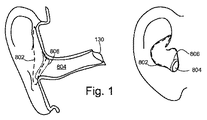
図1は、本願で使用するいくつかの専門用語を説明する目的で、耳の前方横断面図及び側面図を示す。明確にするため、耳毛、外耳道への入口の側面図において多くの人の間で部分的にまたは完全に目立たない特徴を省略する。甲介は、破線802によって全体的に囲まれる耳の歪なボウル状領域である。外耳道804は、甲介を鼓膜130に連結する非直線的な中心線を有する歪な形状のシリンダである。具体的な耳の構造が個人ごとに大きく変化するので、かつ、耳の解剖的部位間の正確な境界が良好に画定されていないので、いくつかの耳要素を正確に説明することは困難である。したがって、本明細書は、線806で全体的に囲まれたボウル状の甲介と外耳道との間の移行領域に言及する。移行領域は、外耳道の一部もしくはボウル状の甲介の一部または双方を含んでもよい。
FIG. 1 shows a front cross-sectional view and a side view of the ear for the purpose of illustrating some terminology used in the present application. For clarity, features that are partially or completely inconspicuous among many people in the side view of the ear hair, the entrance to the ear canal are omitted. The concha is a distorted bowl-shaped region of the ear that is entirely surrounded by a
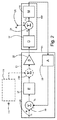
図2を参照すると、例えば特許文献1で説明したような能動雑音低減ANRイヤホンにあるフィードバックループの論理的配置を示すブロックダイアグラムが示されている。信号結合器30は、入力音声信号V1のための端子24に、及びフィードバックプリアンプ35に、動作可能に連結され、いくつかの実施形態において信号結合器30を介して電力増幅器32に順に連結された補償器37に連結されている。電力増幅器32は、外耳道に音響的に連結された音響駆動器17に連結されている。音響駆動器17及び(外耳道に入る雑音P1を示す)端子25は、結合器36によって連結されており、雑音P1及び音響駆動器の出力を示す。結合器36の音響出力P0は、出力プリアンプ35に連結されたマイクロホン11に付与され、この出力プリアンプは、順に信号結合器30に個別に連結されている。端子24、信号結合器30、電力増幅器32、フィードバックプリアンプ35及び補償器37を本明細書では説明せず、以下の図面においてフィードバック回路71として集約的に称する。
Referring to FIG. 2, there is shown a block diagram showing a logical arrangement of feedback loops in an active noise reduction ANR earphone as described in
集約的に、マイクロホン11、音響駆動器17及び結合器36は、ANRイヤホンの前方キャビティ102、すなわち音響駆動器及び鼓膜を音響的に連結する音響空間にある能動フィードバックループの要素を示す。いくつかのANRイヤホンは、同様に、後方キャビティ、すなわち音響駆動器及び環境間にあるキャビティを有しており、この後方キャビティは、主として音響駆動器に取り付けられたバッフルによって前方キャビティから分離されている。存在する場合、後方キャビティは、音響的にまたは圧力的に解放する目的で環境への開口部を有してもよいカバーによって環境から離間されてもよい。
Collectively, the
動作時において、マイクロホン11は、前方キャビティ102から雑音を検出する。フィードバック回路71は、増幅器32へ供給されるフィードバック雑音低減信号を作り出し、この増幅器は、フィードバック雑音低減信号を増幅し、増幅した出力雑音低減信号を音響駆動器17に供給する。音響駆動器17は、出力雑音低減音声信号を音響エネルギーに変換し、この音響エネルギーは、前方キャビティ内へ放射される。
In operation, the
いくつかの実施形態において、フィードバックループは、任意的な(破線で示すような)フィードフォワード雑音低減回路171によって補完される。フィードフォワード回路171は、主としてイヤホンの外側に位置するフィードフォワードマイクロホン111から雑音信号を受け取り、フィードフォワード雑音低減信号を導出し、このフィードフォワード雑音低減信号は、信号結合器230においてフィードバック雑音低減信号とまとめられ、出力雑音低減音声信号を供給する。増幅器は、出力雑音低減音声信号を増幅させ、増幅した出力雑音音声信号を音響駆動器へ供給する。フィードフォワード回路は、主として、適応可能なフィルタを有してもよいフィルタ構造を有する。フィードフォワード雑音低減に適切ないくつかの例にかかる回路は、米国特許第8,144,890号明細書で説明されており、そのすべてを参考として本明細書に組み込む。
In some embodiments, the feedback loop is supplemented by an optional feedforward noise reduction circuit 171 (as shown by the dashed line). The
前方キャビティが大きくなるとより受動的な減衰を可能とするので、前方キャビティは、雑音低減イヤホンの動作に重要であり、この受動的な減衰は、全体的な減衰をより大きくすることもしくは能動雑音低減に関する要件をより低くすることまたは双方を可能とする。ANRイヤホンにおいて、より受動的な減衰を可能とすることに加えて、前方キャビティは、能動雑音低減イヤホンの動作に大きな影響を有する。寸法または幾何形状のような特性は、音響駆動器と鼓膜との間の、マイクロホンと音響駆動器との間の、及び、マイクロホンと鼓膜との間の、移送機能に影響を与える。予想できないかつ一貫性のない移送機能は、結果として、フィードバックループの不安定性を招き、この不安定性は、「スクイール(squeal)」によってあらわされ、この「スクイール」は、スクイールが外耳道内へ直接放射されることがあり、鼻腔を通ってまたはユーザの骨構造を通って内耳へ伝達されることがあるので、イヤホンにとって迷惑である。スクイールを防止することは、例えば、フィードバックループの利得を制限することによって、または、ANR回路が動作する周波数範囲を制限することによって、ANR回路のANR能力を制限することを意味する。 The front cavity is important for the operation of noise reduction earphones, as larger front cavities allow for more passive attenuation, and this passive attenuation can increase overall attenuation or reduce active noise. Enabling lower requirements or both. In addition to allowing more passive attenuation in ANR earphones, the front cavity has a significant impact on the operation of active noise reduction earphones. Properties such as dimensions or geometry affect the transfer function between the acoustic driver and the eardrum, between the microphone and the acoustic driver, and between the microphone and the eardrum. Unpredictable and inconsistent transport functions result in feedback loop instability that is represented by a “squeal” that radiates directly into the ear canal. Can be transmitted through the nasal cavity or through the user's bone structure to the inner ear, which is annoying for the earphones. Preventing squealing means limiting the ANR capability of the ANR circuit, for example, by limiting the gain of the feedback loop or by limiting the frequency range in which the ANR circuit operates.
様々な種類のイヤホンの例を図3A及び図3Bに示す。図3Aは、耳覆い型イヤホンである。耳覆い型イヤホンにおいて、前方キャビティ102は、主として、頭の側部に当接して封止するクッションによって画成される。したがって、例えば米国特許第6,597,792号明細書にあるように、特にクッションによって占有される容積を使用する場合には、大型の前方キャビティを形成できる。耳覆い型イヤホンの前方キャビティの典型的な容積は、114ccである。図3Bは、耳載せ型イヤホンである。耳載せ型イヤホンにおいて、前方キャビティは、外耳に当接して封止するクッションによって画成される。耳覆い型イヤホンのようには前方キャビティを大きく形成することはより困難であるが、前方キャビティは、例えば米国特許第8,111,858号明細書にあるように、前方キャビティの一部としてクッションにより占有される容積を使用することによって、例えば20ccなど依然として比較的大きく形成されることが可能である。
Examples of various types of earphones are shown in FIGS. 3A and 3B. FIG. 3A is an ear covering type earphone. In the ear covering type earphone, the
従来のインナーイヤー式ANRイヤホンの概略図を図4に示す。図4のイヤホンは、音響駆動器217と位置付け及び保持構造体220とを有する。位置付け及び保持構造体は、少なくとも4つの機能を有する。この構造体は、イヤホンを挿入したときに耳にイヤホンを位置合わせし;この構造体は、外耳道で封止を形成して環境騒音が外耳道に入ることを防止し;この構造体は、イヤホンを所定位置で保持し、そのため、ユーザの頭が動いても、イヤホンは所定位置のままであり;この構造体は、音響駆動器から外耳道への通路を形成する。外耳道のサイズ及び幾何形状が個人ごとに大きく異なるので、かつ、外耳道の壁が痛みに敏感でありかつイヤホンのうち耳内へ突出する部分によって損傷されることがあるので、位置付け及び位置合わせ構造は、主として、軟質の適合可能な材料で形成されており、そのため、位置付け及び保持構造体は、外耳のサイズ及び幾何形状に適合でき、ユーザの外耳に痛みや損傷を引き起こさない。主として、適合可能な材料は、シリコーンなど発泡性または中実のエラストマからなるいくつかのタイプである。イヤホンを耳内で保持するため、かつ、有効的な封止を形成するため、位置付け及び保持構造体220は、外耳道内に突出する。しかしながら、図4に示すように、位置付け及び保持構造体は、外耳道内に位置し、これにより、外耳道の有効容積を低減する。このため、設計のトレードオフがある、すなわち、位置付け及び保持構造体の壁部が厚すぎる場合には、壁部は、前方キャビティの容積を低減し、音響駆動器と鼓膜との間の経路の横断面積は、望ましいことにとどまらない;しかし、壁部が薄すぎる場合には、位置付け及び保持構造体は、外耳道を適切に封止しないことがあり、雑音が外耳道の中に入ることを適切に防止できないことがあり、イヤホンを所定位置で保持するための十分な構造的強度または安定性を有しないことがある。
A schematic diagram of a conventional inner-ear ANR earphone is shown in FIG. The earphone of FIG. 4 includes an
あるいは、適合可能な材料は、連続気泡発泡体であってもよく、この発泡体は、発泡体の容積を前方キャビティの一部として使用することを可能とするが、連続気泡発泡体は、音響的に半透過性を有しており、そのため、受動減衰を損なわせる。同様に、位置付け及び保持構造体が外耳道内へ突出しすぎる場合、前方キャビティの容積は、望ましいことにとどまらない;しかし、位置付け及び保持構造体が外耳道内へ十分には突出していない場合、適切には封止しないことがあり、イヤホンを所定位置で保持しないことがある。 Alternatively, the adaptable material may be an open cell foam that allows the foam volume to be used as part of the front cavity, but the open cell foam is acoustic Semi-transparent, and thus impairs passive attenuation. Similarly, if the positioning and holding structure protrudes too far into the ear canal, the volume of the anterior cavity is not desirable; however, if the positioning and holding structure does not protrude sufficiently into the ear canal, It may not be sealed and the earphone may not be held in place.
図4に示すタイプのイヤホンの音響駆動器は、主として、音響駆動器が通路に結合する位置において、音響駆動器217の軸230が音響駆動器から外耳道への通路の中心線232とほぼ平行であるまたは(この例において)一致する。この配置により、音響駆動器の直径は、甲介のボウル状の外耳道への入口の直径に、または外耳の他の特徴に制限される。例えば音響駆動器217’のような大型の駆動器を用いることが望ましい場合、音響駆動器は、機械的に完全に支持されていない必要がある。大型の音響駆動器がイヤホンの他の部分に対して大きな質量を有するので、支持されていない質量は、イヤホンを耳の中で機械的に不安定にさせる。素子132及び134を後述する。マイクロホンのような主としてインナーイヤー式ANRイヤホンのいくつかの素子をこの図面では示さない。
The acoustic driver of the earphone of the type shown in FIG. 4 is such that the
外耳道に係合する位置付け及び保持構造体の代替物は、米国特許第6,683,965号明細書に示すようなヘッドバンドである。ヘッドバンドは、インナーイヤー式イヤホンの一部のユーザによって望ましくないと考えられる。 An alternative to a positioning and holding structure that engages the ear canal is a headband as shown in US Pat. No. 6,683,965. Headbands are considered undesirable by some users of inner-ear earphones.
イヤホンを位置付けて保持することの機械的な困難性に加え、小型の前方キャビティのインナーイヤー式ANRイヤホンは、ANRイヤホンのフィードバックループの設計にさらなる困難を形成する。前方キャビティは、外耳道を含む。外耳道の容積及び幾何形状は、個人ごとに著しく異なる。耳覆い型及び耳載せ型イヤホンにおいて、耳の寸法及び構造におけるバラツキは、ANRシステムの動作に小さな影響しか与えない。しかしながら、インナーイヤー式イヤホンを用いると、外耳道は、前方キャビティのうちのかなりの部分である。したがって、外耳道の寸法及び幾何形状のバラツキは、ANRシステムに大きな影響を与え、また、外耳道に係合するイヤホンの部分の閉塞、捻れまたは狭窄は、ANRシステムの動作に大きな影響を与える。しかしながら、閉塞、捻れ及び狭窄を防止することを試みることは、外耳道内へ突出するイヤホンの部分の適合性及び快適性の目的とは矛盾する。 In addition to the mechanical difficulties of positioning and holding the earphones, the small front cavity inner-ear ANR earphones create additional difficulties in the design of the feedback loop of the ANR earphones. The anterior cavity includes the ear canal. The volume and geometry of the ear canal varies significantly from individual to individual. In ear-covered and ear-mounted earphones, variations in ear dimensions and structure have only a minor effect on the operation of the ANR system. However, with inner ear earphones, the ear canal is a significant portion of the anterior cavity. Thus, variations in the dimensions and geometry of the ear canal have a significant impact on the ANR system, and occlusion, twisting or stenosis of the portion of the earphone that engages the ear canal has a significant impact on the operation of the ANR system. However, attempting to prevent occlusion, twisting and stenosis is inconsistent with the purpose of compatibility and comfort of the portion of the earphone that protrudes into the ear canal.
図5は、ANRシステムで使用するのに適したインナーイヤー式イヤホン110を示す。イヤホン110は、ケーブル配線などを位置付けるためのステム152と、音響駆動器モジュール114と、チップ160と、を有する。いくつかのイヤホンは、ステム152を有さないが、外部デバイスとの無線通信のための電子モジュール(図示略)を有してもよい。他のイヤホンは、ステム及び音響駆動器モジュールを有さず、受動イヤプラグとして機能する。チップ160は、位置付け及び保持構造体120を有し、この構造体は、この例において、外側脚部122及び内側脚部124を有する。チップは、同様に、封止構造体48を有し、外耳道への開口部に当接して封止し、前方キャビティを形成する。
FIG. 5 shows an inner-
外側脚部122及び内側脚部124は、音響駆動器モジュール114から延在する。2つの脚部それぞれは、一端部において本体部に接続されている。外側脚部は、甲介の後方において対輪壁の湾曲をほぼ辿るように湾曲されている。各脚部の第2端部は、結合されている。結合した内側及び外側脚部は、取付点を超えて先端の位置付け及び保持構造体まで延在する。適切な位置付け及び保持構造体は、米国特許出願第12/860,531号で説明されており、そのすべてを参照として本明細書に組み込む。一実施形態において、封止構造体48は、適合可能な円錐台状の構造体であり、この構造体は、イヤホンを外耳道へ押し込むと、内側に反る。構造体は、甲介のボウル部と外耳道との間の移行領域において外耳の外観と一致し、外耳道を封止して環境騒音が外耳道へ入ることを阻止する。1つのこのような封止構造体は、米国特許出願第13/193,288号で説明されており、そのすべてを参照として本明細書に組み込む。位置付け及び保持構造体と封止構造体48との組み合わせにより、機械的安定性を提供する。内側への圧力をかけてイヤホンを所定位置で保持するためのヘッドバンドまたは他のデバイスを必要としない。イヤホンは、従来の位置付け及び保持構造体に関する限りでは、外耳道内へ突出する必要はない。いくつかの場合において、封止構造体48自体は、イヤホンを耳内へ位置付けて保持するのに十分である。位置付け及び保持構造体は、さらなる機械的安定性を提供し、頭のさらなる急激な運動を可能とする。
図6は、ユーザの耳内にある図5のイヤホンの一部を示す。詳細を示すため、いくつかの実施形態において、音響駆動器モジュール114、封止構造体48及びステム152のようなものを省略し、チップ160を部分的に切除する。位置付け及び保持構造体120は、外耳の外観と係合し、そのため、音響駆動器モジュール(音響駆動器を含む)は、イヤホンを使用するときにイヤホンの大部分が耳の甲介の外側にあるにもかかわらず、ユーザの耳に対して機械的に安定する。音響駆動器モジュールを耳の甲介のほぼ外側に位置付けすることにより、音響駆動器を甲介内に(または部分的にもしくは完全に外耳道内に)嵌め込まなければならないイヤホンで使用するよりも、ヘッドバンドを使用することなくかつイヤホンを外耳道内へ深く延在させる必要なく、十分に大型の音響駆動器を使用することが可能となる。大型の音響駆動器を用いることにより、特にうるさい環境において、低周波数におけるより良好な雑音除去性能を可能とする。一実施形態において、直径が公称14.8mmである音響駆動器を使用する。主として、音響駆動器は、甲介内に嵌め込むために、直径で10mm未満でなければならない。
FIG. 6 shows a portion of the earphone of FIG. 5 in the user's ear. To show details, in some embodiments, such as
図7Aは、横断平面で破断して下方から見た、ユーザの右耳内の所定位置にある図5及び図6のイヤホンの実際の実施を示す横断面図である。音響駆動器17は、ノズル70、すなわち音響駆動器17と外耳道とを音響的に結合する経路によって外耳道75へ音響的に結合されている。外耳道の封止された部分77と鼓膜の前方の空間73とノズル70とは、イヤホンの前方キャビティを形成する。図4の構造を有するイヤホンにおいて、ノズルは、位置付け及び保持構造体の一部またはすべてを含んでもよい。ノズルは、硬質セクション72と弾性セクション67とを有してもよく、ノズルの全長は、約10mmから12mmである。ノズルは、例えば約5.3mmの主軸及び約3.6mmの副軸を有する楕円開口部を有し、横断面積は、約15mm2から16mm2であり、容積は、約150mm3から190mm3である。
FIG. 7A is a cross-sectional view showing the actual implementation of the earphones of FIGS. 5 and 6 in a predetermined position in the user's right ear, as viewed from below, broken at the transverse plane. The
ANRイヤホンによってもたらされる能動減衰量は、前方キャビティのインピーダンスによって制限される。一般的に、インピーダンスを低減することによって前方キャビティが小さくなっても、低いインピーダンスは好ましい。一般的に、インピーダンスを低減することに起因した能動雑音低減における改善は、前方キャビティを小さくすることに起因した受動低減における低減を相殺するにとどまらない。インピーダンスは、いくつかは関連するさまざまな方法によって低減されてもよい。インピーダンスは、周波数依存性を有しており、広い範囲の周波数にわたって、または少なくともANRシステムが動作する範囲の周波数にわたって、インピーダンスを低減することは、望ましい。例えば双方とも絶対項において音響駆動器と鼓膜との間の音響経路の横断面積を増大させることによって、音響駆動器と鼓膜との間の音響経路の横断面積に対する音響経路の長さとの間の比率を低減することによって、及び、前方キャビティの音響質量を低減することによって、インピーダンスを広範囲の周波数にわたって低減してもよい。前方キャビティの構成部材において、音響駆動器の前方の空間(図7Aの符号73)の寸法を変更することによってインピーダンスを十分に低減することを実現することは困難であり、外耳道の横断面積を増大させるまたは外耳道の音響質量を増大させることは不可能でありまたは少なくとも非常に実行不可能であり、そのため、広範囲の周波数にわたって前方キャビティのインピーダンスを低減させる最も有効な方法は、ノズル70の横断面積(ノズルの全長にわたって均一な横断面積を有していないノズルに関してノズルの平均横断面積に、または、特定すればノズルの最小横断面積に、言及する)を増大させることによって、ノズル横断面積に対するノズル長さの比率を低減することによって、及び、ノズルの音響質量を低減することによって、ノズル70のインピーダンスを低減することである。一般的に、100Hzにおいて8×105[kg/(m4×sec)]未満、好ましくは7×105[kg/(m4×sec)]未満の絶対値|z|を有しかつ1kHzにおいて8×106[kg/(m4×sec)]未満、好ましくは7×106[kg/(m4×sec)]未満の絶対値|z|を有するインピーダンスは、受動減衰を著しく低減させることなく能動雑音減衰における著しい改善をもたらす。インピーダンスは、2つの成分、抵抗成分(直流流れ抵抗R)と無効成分または質量成分jωMとを有しており、ここで、Mは、後述する音響質量である。これら2つの成分において、jωM項は、R項よりもかなり大きい。例えば、1つの実施において、100Hzにおける全インピーダンスの絶対値または強度は、6.47×105[kg/(m4×sec)]であり、質量インピーダンスは、6.46×105[kg/(m4×sec)]である。したがって、以降、質量インピーダンスのみを考慮する。上述した値未満の質量インピーダンスは、これを通って音響エネルギー伝播できる横断面積Aが少なくとも7.5mm2であり好ましくは10mm2であるノズルの組み合わせを提供することによって、得られ、比率l/A(ここでlはノズル長)は、1000[m/m2]未満であり好ましくは900[m/m2]未満であり、音響質量Mは、1200[kg/m4]未満であり好ましくは1100[kg/m4]未満であり、ここで、M=ρl/Aであり、ρは空気の密度(実測が困難であるまたは不可能である場合、1.2[kg/m3]と推測される)。図7における一実施形態にかかるイヤホンにおいて、横断面積ANRは、約1.4×10−5m2から1.6×10−5m2(14mm2から16m2、比率l/Aは625[m/m2]と857[m/m2]の間)であり、音響質量は、750[kg/m4]及び1029[kg/m4]の間であり、質量インピーダンスの絶対値は、100Hzにおいて4.7×105[kg/(m4×sec)]及び6.5×105[kg/(m4×sec)]の間、1kHzにおいて4.7×106[kg/(m4×sec)]及び6.5×106[kg/(m4×sec)]である。
The active attenuation provided by ANR earphones is limited by the impedance of the front cavity. In general, a low impedance is preferred even if the front cavity becomes smaller by reducing the impedance. In general, the improvement in active noise reduction due to reducing impedance goes far beyond the reduction in passive reduction due to smaller front cavities. Impedance may be reduced by various related methods. The impedance is frequency dependent and it is desirable to reduce the impedance over a wide range of frequencies, or at least over the range of frequencies where the ANR system operates. The ratio between the length of the acoustic path to the cross-sectional area of the acoustic path between the acoustic driver and the eardrum, for example by increasing the cross-sectional area of the acoustic path between the acoustic driver and the eardrum, both in absolute terms The impedance may be reduced over a wide range of frequencies by reducing and by reducing the acoustic mass of the front cavity. It is difficult to realize a sufficient reduction in impedance by changing the size of the space in front of the acoustic driver (reference numeral 73 in FIG. 7A) in the component of the front cavity, which increases the cross-sectional area of the ear canal It is impossible or at least very impractical to increase or increase the acoustic mass of the ear canal, so the most effective way to reduce the impedance of the anterior cavity over a wide range of frequencies is the cross-sectional area of the nozzle 70 ( The nozzle length relative to the nozzle cross-sectional area by increasing the average cross-sectional area of the nozzle for nozzles that do not have a uniform cross-sectional area over the entire length of the nozzle, or, in particular, the minimum cross-sectional area of the nozzle, And reducing the acoustic mass of the nozzle by reducing the ratio of Therefore, it is possible to reduce the impedance of the
イヤホンが位置付け及び保持構造体120を有するので、ノズルは、ユーザの耳内でイヤホンを位置付けて保持することを実行する必要がなく、外耳道を適切に封止するのに必要なものを超えて耳に接触する必要がない。したがって、ノズルの構造、寸法及び材料は、機械的要件よりもむしろ音響及び快適性を考慮して選択されてもよい。例えば、ノズルは、少なくとも部分的に外耳道の最も幅広の部分の横断面積と同じ大きさの横断面積を有してもよく、これにより、インピーダンスを低減する。
Since the earphone has a positioning and holding
イヤホンは、ノズルを阻害するまたは閉塞する可能性を減少させるために様々な機能を有する。ノズルが従来のイヤホンのようには外耳道内へ遠くまで延在しないので、耳の幾何形状及びサイズにおけるユーザのバラツキに対してユーザによって引き起こされる阻害または閉塞の影響を受けにくい。硬質セクション72は、弾性セクションの過剰な変形に抗し、一方、弾性セクションは、不快を発生させることなくイヤホンがユーザの耳のサイズ及び幾何形状に適合することを可能とする。一実施において、硬質セクションは、アクリロニトリル・ブタジエン・スチレン(またはABS)で形成されており、弾性セクションは、シリコーンで形成されている。素子81及び83を後述する。
Earphones have various functions to reduce the possibility of blocking or blocking the nozzle. Since the nozzle does not extend as far into the ear canal as conventional earphones, it is less susceptible to blockage or blockage caused by the user to user variations in ear geometry and size. The rigid section 72 resists excessive deformation of the elastic section, while the elastic section allows the earphone to fit the size and geometry of the user's ear without causing discomfort. In one implementation, the rigid section is made of acrylonitrile butadiene styrene (or ABS) and the elastic section is made of silicone. The
再び図7Aを参照すると、硬質セクションの端部においてメッシュスクリーン79があり、このメッシュスクリーンは、破片が音響駆動器モジュール14に入ることを防止する。メッシュは、例えば約6レイリーなど30レイリー未満の低音響抵抗を有する。
Referring again to FIG. 7A, there is a
図7Bは、ユーザの耳の外観のない図7Aの一実施を示す。ノズルの一端部は、音響駆動器薄膜78の縁部76に近接して位置する。音響駆動器の軸330は、軸330に平行または一致する線がノズルの中心線332と角度θ>30°、好ましくはθ>45°で交差するように方向付けられている。一実施において、θ≒78°である。
FIG. 7B shows one implementation of FIG. 7A without the appearance of the user's ear. One end of the nozzle is located close to the
図8Aから図8Eは、図7の角度θを示す概略図である。図8A及び図8Bは、「フェイスファイア(facefire)」配置を示し、θ=0°である。図8Aにおいて、音響駆動器の軸330及びノズルの中心線332は、一致し、図8Bにおいて、音響駆動器の軸330とノズルの中心線とは、平行である。図8Cは、「エッジファイア(edgefire)」配置であり、θ=90°である。図8D及び図8Eは、「フェイスファイア」配置と「エッジファイア」配置との間の配置を示す。図8Dにおいて、θ=30°であり、図8Eにおいて、θ=45°である。
8A to 8E are schematic diagrams showing the angle θ of FIG. 8A and 8B show a “facefire” arrangement, where θ = 0 °. In FIG. 8A, the
図9を参照すると、望ましいことは、米国特許第8,077,874号明細書で説明するように、薄膜78を音響駆動器のボイスコイルに取り付ける点311に径方向で近接する点511Aにおいてマイクロホンを配置し、薄膜78からの音響エネルギーの放射とマイクロホン11による音響エネルギーの測定との間の時間遅延を最小化することである。一般的に、マイクロホンが薄膜からさらに離間するようにマイクロホンの位置を変更することは、マイクロホンを薄膜に対して異なる径方向位置になるようにマイクロホンを変更するよりも時間遅延に関して大きな悪影響を有する。マイクロホンを鼓膜に近接して、例えばノズルに配置することにより、より緩やかな圧力勾配をもたらし、この圧力勾配は、より大きな能動雑音低減を可能とする。「フェイスファイア」方位とした従来の能動雑音低減設定において、マイクロホンを鼓膜に近接するように移動させて圧力勾配を改善することは、マイクロホンを薄膜から離間するように移動させ、これは、時間遅延に悪影響を及ぼす。したがって、マイクロホンの配置を変更して圧力勾配を改善することは、時間遅延を悪化させ、マイクロホンの配置を変更して時間遅延を改善することは、圧力勾配を悪化させる。
Referring to FIG. 9, it is desirable to have a microphone at
図9は、マイクロホンの場所を点511A(ボイスコイルと薄膜との取付点311の上方にある)から点511B(鼓膜により近く、ノズルに近接するまたはノズル内にある)に変更した例を示す。矢印512で示す場所の変更は、矢印523で示す薄膜から離間する成分と、矢印524で示す薄膜を横断する成分と、を有する。薄膜から離間するように場所を変更すること(cosθに比例する)は、時間遅延に悪影響を与える。薄膜を横断するように場所を変更すること(sinθに比例する)は、時間遅延に悪影響を与えない、すなわち、薄膜から離間するように場所を変更することのようには悪影響を与えない。「フェイスファイア」方位において、θ=0°であり、そのため、cosθ=1かつsinθ=0であり、それにより、鼓膜に向かうようにかつノズルに向かうようにもしくはノズル内になるように場所を変更することは、薄膜から離間するように場所を変更することに等しい結果になる。「エッジファイア」方位において、θ=90°であり、そのため、cosθ=0°かつsinθ=1であり、それにより、薄膜から離間するようには場所を変更しない結果になる。θ=30°に関して、図5Eに示すように、薄膜を横断するように場所を変更する量は、薄膜から離間するように場所を変更する量の0.5倍であり、θ=45°に関して、ノズル内になるように場所を変更することは、薄膜を横断するように場所を変更する量と薄膜から離間するように場所を変更する量とが等しい結果となる。θ=78°である実際の実施に関して、鼓膜に向けてノズル内へ5単位だけ場所を変更することは、約1単位薄膜を横断するように場所を変更する結果となる。
FIG. 9 shows an example in which the location of the microphone is changed from
図7Aを再び参照すると、(線81によって全体的に示される)音響駆動器17の実質的な部分は、ユーザの甲介の外側に位置する。位置付け及び保持構造体120は、外耳の外観83に係合し、ヘッドバンドの必要なくイヤホンを所定位置で保持する。
Referring again to FIG. 7A, a substantial portion of the acoustic driver 17 (shown generally by line 81) is located outside the user's concha. The positioning and holding
ノズルを閉塞する可能性を減少させる機能に加えて、イヤホンは、阻害または閉塞からの悪影響を低減するための他の機能を有してもよい。機能の1つを後述する。 In addition to the ability to reduce the likelihood of clogging the nozzle, the earphone may have other functions to reduce the negative effects from inhibition or clogging. One of the functions will be described later.
図10A及び図10Bは、イヤホンの別の機能を示す。図10Aは、図5及び図7のANRイヤホンにおいて実施されているような図2のフィードバックループを示す。フィードバックループを採用するANRイヤホンの前方キャビティ102は、音響容積vを含み、この音響容積vは、図5のノズル70の容積vnozzlleにユーザの外耳道の容積vearcanalを加えたものを有する。前方キャビティは、同様に、鼓膜の音響抵抗reardrumを示す音響抵抗によって特徴付けられる。reardrum及び容積vは、共にインピーダンス zinternalを形成する。図10Bに示すように、前方キャビティの幾何形状及び寸法と鼓膜の抵抗とは、伝達関数Gds、すなわち音響駆動器17からマイクロホン11までの伝達関数を決定する要素の中にある。
10A and 10B show another function of the earphone. FIG. 10A shows the feedback loop of FIG. 2 as implemented in the ANR earphones of FIGS.
幾何形状、寸法、音響抵抗またはインピーダンスが設計しているフィードバックループで使用した幾何形状、寸法、音響抵抗またはインピーダンスとは異なる(例えば、図11Aのように、ノズルをv≠vearpiece+vearcanal例えばv=vearpieceとなるように閉塞している)場合、伝達関数は、いくつかの別の関数、例えば図11のG’dsであってもよく、この伝達関数は、フィードバックを不安定にさせるまたは実行を低迷させる。例えば、図12A及び図12Bそれぞれは、ノズルを閉塞している状態の伝達関数の強度(97B)及び(位相98B)と比較した伝達関数Gdsの強度(97A)及び(位相98A)を示す。2つの曲線は、1kHzにおいて約20dBだけ、1kHzから3kHzの間で45°から90°だけ、分岐している。
The geometry, dimensions, acoustic resistance or impedance is different from the geometry, dimensions, acoustic resistance or impedance used in the designed feedback loop (for example, as shown in FIG. 11A, the nozzle is v ≠ v earpiece + v earcanal, eg, v = V earpiece ), the transfer function may be some other function, eg G ′ ds in FIG. 11, which makes the feedback unstable or Slow execution. For example, FIGS. 12A and 12B show the transfer function strength (97A) and (
図13A及び図13Bは、ノズルの阻害及び閉塞がフィードバックループを不正確にさせるのに十分なほど伝達関数を変化させる可能性を減少させる構成を示す。図13Aの構成において、前方キャビティ102は、インピーダンスzexternalのシャント80によって環境に連結されている。シャント80は、ノズルの阻害及び閉塞がフィードバックループを不正確にさせる可能性を減少させる。インピーダンスzexternalは、低周波数において低く、かつ高周波数においてzinternalよりも多きいべきである。シャントは、開口部にあるインピーダンス提供構造体を有する環境への開口部であってもよい。インピーダンス提供構造体は、図13Aに示すような抵抗性スクリーン82であってもよい。あるいは、シャントは、イヤホンの外殻に音響的抵抗穴部を形成することによって、または、インサートであって穴部がこのインサートに形成されているインサートによって、形成されてもよい。シャントにより、音響駆動器は、インピーダンスzexternalによって環境に、及び、図13Bに示す伝達関数Gdsによってフィードバック回路71に、音響的に連結される。
FIGS. 13A and 13B show a configuration that reduces the likelihood of nozzle transfer and blockage changing the transfer function enough to cause the feedback loop to be inaccurate. In the configuration of FIG. 13A, the
図14において、シャント80は、図12の開口部及びスクリーン82を有する。あるいは、開口部80及びスクリーン82は、発泡体86を充填した管体84によって環境に連結されてもよい。管体は、インピーダンスzexternalを判断することをより正確にすることをもたらし、発泡体は、管体内で発生することがある共鳴を減衰させる。他の構成は可能であり、例えば、管体84の外端部88に抵抗性スクリーンがあってもよく、または、管体84の開口部80及び外端部88に抵抗性スクリーンがあってもよい。
In FIG. 14, a
図15A及び図15Bそれぞれは、ノズルが閉塞されていない(曲線97B)及び閉塞されている(曲線98B)図9にかかるイヤホンの伝達関数Gdsの強度及び位相を示す。曲線は、図8の曲線よりも分岐していない。
15A and 15B respectively show the intensity and phase of the transfer function G ds of the earphone according to FIG. 9 in which the nozzle is not blocked (
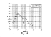
図16は、シャントがある及びシャントがない前の図のシステムマイクロホン11における全能動除去を示す。曲線83で示すシャントがない場合、約300Hzと800Hzとの間には、0dB未満への顕著な落ち込みがある。曲線85で示すシャントがある場合、落ち込みがなく、そのため、約700Hzと1kHzとの間には、2つの構成間で10dB以上の差がある。
FIG. 16 shows full active removal in the
図17は、シャント80の作用の一例を示す。図17は、周波数の関数としての強度|z|を示す。曲線90は、前方キャビティのインピーダンスの強度を示す。低周波数において、例えば約100Hz未満において、前方キャビティのインピーダンスは、非常に高く、インピーダンスは、約1kHzにおいて最大に達し、高周波数において増大する。曲線91は、シャントのインピーダンスの強度|zexternal|を示す。低周波数において、約1kHz未満において、シャントのインピーダンスは、非常に低い。1kHz以降、インピーダンスは、前方キャビティの及び鼓膜のインピーダンスよりも急速に増大する。このため、1kHz未満の周波数において、シャントのインピーダンスは、優位であり、約1kHzを超える周波数において、前方キャビティのインピーダンスは、優位である。
FIG. 17 shows an example of the action of the
シャント80を採用することは、受動雑音減衰と能動雑音減衰との間にトレードオフを必要とする。トレードオフを図18に示し、この図は、周波数に対するdBにおける減衰の点である(垂直軸において正の値が大きくなると、より大きい減衰を示す)。図18において、曲線92は、シャントを有するイヤホンによってもたらされる受動減衰を示し、曲線93は、シャントを有さないイヤホンによってもたらされる受動減衰を示す。受動減衰が優位である約1kHzを超える周波数範囲において、例えばf1などの任意の既知の周波数では、シャントを有さないイヤホンによってもたらされる受動減衰は、シャントを有する受動減衰よりも大きい。曲線94は、シャントを有するイヤホンによってもたらされる能動減衰を示し、曲線95は、シャントを有さないイヤホンによってもたらされる能動減衰を示す。能動減衰が優位である約1kHz未満の周波数範囲において、例えばf2などの任意の既知の周波数では、シャントを有するイヤホンによってもたらされる減衰は、シャントを有さないイヤホンによってもたらされる減衰よりも大きい。
Employing
全減衰の観点から見ると、シャントを有さないイヤホンは、低周波数において減衰が小さく、高周波数において減衰が大きくなる一方、シャントを有するイヤホンについてはその逆が当てはまり、そのため、もたらされる全減衰において著しい差異はない。しかしながら、ノズルを閉塞するまたは阻害する場合に、もたらされる減衰及び良好な安定性に加え、図13及び図14の構造が有利である別の理由がある。例えば、シャントは、周囲の音に関して及びユーザに起因する音(例えば、ユーザが、外耳道を通して、骨構造を通して及び鼻道を通して、伝達された自身の声を聴く)に関してより自然な音を提供する。シャントがないと、イヤホンは、耳栓のように機能し、そのため、鼓膜に達する周囲の音は、「低音が大きすぎ(boomy)」、「籠った(stuffy)」音を有する。シャントがあると、周囲の音及びユーザに起因する音は、より自然な音を有する。 From the point of view of total attenuation, an earphone without a shunt has low attenuation at low frequencies and high attenuation at high frequencies, while the opposite is true for earphones with a shunt, so There is no significant difference. However, in addition to the damping and good stability provided when blocking or obstructing the nozzle, there are other reasons why the structures of FIGS. 13 and 14 are advantageous. For example, the shunt provides a more natural sound with respect to ambient sounds and sounds that originate from the user (eg, the user listens to his / her voice transmitted through the ear canal, through the bone structure and through the nasal passage). Without a shunt, the earphone functions like an earplug, so the ambient sound that reaches the eardrum has a “boomy” and “stuffy” sound. With a shunt, ambient sounds and user-generated sounds have a more natural sound.
本明細書で開示した具体的な器具及び技術のさまざまな用途及び具体的な器具及び技術からの逸脱は、本発明のコンセプトから逸脱することなくなされてもよい。したがって、本発明は、本明細書で開示した新規な特徴及び新規な特徴の組合せそれぞれ及びすべてを包括しており、添付の特許請求の範囲の精神及び範囲によってのみ限定されると解される。 Various uses of the specific devices and techniques disclosed herein and departures from the specific devices and techniques may be made without departing from the inventive concept. Accordingly, it is to be understood that the invention encompasses each and every novel feature and combination of novel features disclosed herein and is limited only by the spirit and scope of the appended claims.
11 システムマイクロホン,マイクロホン、17 音響駆動器、30 信号結合器、32 電力増幅器,増幅器、48 封止構造体、70 ノズル、71 フィードバック回路、75 外耳道、78 音響駆動器薄膜,薄膜、79 メッシュスクリーン、80 シャント,開口部、82 抵抗性スクリーン,スクリーン、102 前方キャビティ、110 インナーイヤー式イヤホン,イヤホン、111 フィードフォワードマイクロホン、120 保持構造体、130 鼓膜、171 フィードフォワード回路、217,217’ 音響駆動器、220 位置付け及び保持構造体 11 system microphone, microphone, 17 acoustic driver, 30 signal coupler, 32 power amplifier, amplifier, 48 sealing structure, 70 nozzle, 71 feedback circuit, 75 ear canal, 78 acoustic driver thin film, thin film, 79 mesh screen, 80 shunts, openings, 82 resistive screens, screens, 102 front cavities, 110 inner ear earphones, earphones, 111 feed forward microphones, 120 holding structures, 130 tympanic membranes, 171 feed forward circuits, 217, 217 ′ acoustic drivers, 220 Positioning and holding structure
Claims (15)
能動雑音低減(ANR)イヤホンのためのイヤホンであって、
− 当該イヤホンをユーザの耳内で位置付けて保持するように外耳に係合するための構造体と、
− ユーザの外耳道で当該イヤホンを封止するための構造体であって、当該イヤホンの内側にある第1容積の空間とユーザの外耳道の内側にある第2容積の空間とを有する前方キャビティを形成し、封止するための当該構造体が、前記第1容積の空間と前記第2容積の空間とを連結するノズルの少なくとも一部を含む、構造体と、
− 能動雑音低減回路であって、
・ 前記前方キャビティ内の雑音を検出するために、前記第1容積の空間に音響的に連結されたフィードバックマイクロホンと、
・ フィードバック雑音除去音声信号を供給するために前記フィードバックマイクロホンに応答するフィードバック回路と、
・ フィードバック雑音除去音声信号を備える出力雑音除去音声信号を雑音除去音響エネルギーに変換し、前記雑音除去音響エネルギーを前記前方キャビティ内へ送達させる音響駆動器と、
を備える能動雑音低減回路と、
を備えるイヤホンを備え、
前記ノズルが、少なくとも10mm2の開口横断面積を有し、100Hzにおいて、800×10 3 [kg/(m 4 ×sec)]未満でありかつ1kHzにおいて8×10 6 [kg/(m 4 ×sec)]未満である音響インピーダンス強度|z|を有し、
ここで、|z|=Mfであり、M=ρl/Aであり、ρが空気の密度であり、Aが当該ノズルの開口横断面積であり、lが前記ノズルの長さであることを特徴とする装置。 A device,
An earphone for an active noise reduction (ANR) earphone,
-A structure for engaging the outer ear to position and hold the earphone in the user's ear;
A structure for sealing the earphone in the user's ear canal, forming a front cavity having a first volume space inside the earphone and a second volume space inside the user's ear canal; And the structure for sealing includes at least a part of a nozzle connecting the space of the first volume and the space of the second volume ; and
An active noise reduction circuit comprising:
A feedback microphone acoustically coupled to the space of the first volume for detecting noise in the front cavity ;
A feedback circuit responsive to the feedback microphone to provide a feedback denoising audio signal;
· Converting the output noise cancellation sound signal comprising feedback noise cancellation sound signal to the noise removal acoustic energy, and acoustic driver to the noise removing acoustic energy Ru is delivered into the forward cavity,
An active noise reduction circuit comprising:
Bei example an earphone with a,
Before SL nozzle, have a opening cross-sectional area of at least 10 mm 2, at 100Hz, 800 × 10 3 [kg / (m 4 × sec)] less than a is and 8 × 10 6 [kg / ( m 4 × at 1kHz sec)] having an acoustic impedance strength | z |
Here, | z | a = Mf, is M = ρl / A, ρ is the density of air, A is an opening cross-sectional area of the nozzle, l the length der Rukoto of the nozzle Features device.
前記ノズルが、甲介のボウル部と外耳道への入口との間の移行部において外耳道で音響的に封止し、キャビティを形成することを特徴とする請求項1に記載の装置。 The nozzle, have a 1000 [m / m 2] following ratios l / A,
Before SL nozzles, acoustically sealed by the ear canal at the transition between the entrance to concha of the bowl portion and the ear canal, device according to claim 1, characterized in that to form a cavity.
前記開口部内にあるインピーダンス提供構造体と、
をさらに備えることを特徴とする請求項1に記載の装置。 An opening connecting the front cavity to the environment;
An impedance providing structure in the opening;
The apparatus of claim 1 , further comprising:
フィードフォワード雑音除去音声信号を供給するために、前記フィードフォワードマイクロホンに応答するフィードフォワード回路と、
前記フィードバック雑音除去音声信号と前記フィードフォワード雑音除去音声信号とを結合し、出力雑音除去音声信号を供給するための回路と、
をさらに備えることを特徴とする請求項1に記載の装置。 A feedforward microphone for detecting noise outside the earphone;
A feedforward circuit responsive to the feedforward microphone to provide a feedforward denoising audio signal;
A circuit for combining the feedback denoising audio signal and the feedforward denoising audio signal to provide an output denoising audio signal;
The apparatus of claim 1 , further comprising:
Applications Claiming Priority (3)
| Application Number | Priority Date | Filing Date | Title |
|---|---|---|---|
| US13/480,766 | 2012-05-25 | ||
| US13/480,766 US9082388B2 (en) | 2012-05-25 | 2012-05-25 | In-ear active noise reduction earphone |
| PCT/US2013/042231 WO2013177285A1 (en) | 2012-05-25 | 2013-05-22 | In-ear active noise reduction earphone |
Related Child Applications (1)
| Application Number | Title | Priority Date | Filing Date |
|---|---|---|---|
| JP2016187934A Division JP6215428B2 (en) | 2012-05-25 | 2016-09-27 | Inner ear noise reduction earphone |
Publications (2)
| Publication Number | Publication Date |
|---|---|
| JP2015521008A JP2015521008A (en) | 2015-07-23 |
| JP6017682B2 true JP6017682B2 (en) | 2016-11-02 |
Family
ID=48538082
Family Applications (3)
| Application Number | Title | Priority Date | Filing Date |
|---|---|---|---|
| JP2015514153A Active JP6017682B2 (en) | 2012-05-25 | 2013-05-22 | Inner ear noise reduction earphone |
| JP2016187934A Active JP6215428B2 (en) | 2012-05-25 | 2016-09-27 | Inner ear noise reduction earphone |
| JP2017179952A Active JP6556795B2 (en) | 2012-05-25 | 2017-09-20 | Inner ear noise reduction earphone |
Family Applications After (2)
| Application Number | Title | Priority Date | Filing Date |
|---|---|---|---|
| JP2016187934A Active JP6215428B2 (en) | 2012-05-25 | 2016-09-27 | Inner ear noise reduction earphone |
| JP2017179952A Active JP6556795B2 (en) | 2012-05-25 | 2017-09-20 | Inner ear noise reduction earphone |
Country Status (7)
| Country | Link |
|---|---|
| US (3) | US9082388B2 (en) |
| EP (2) | EP2856771B1 (en) |
| JP (3) | JP6017682B2 (en) |
| CN (2) | CN104429097B (en) |
| HK (1) | HK1207232A1 (en) |
| MY (1) | MY168899A (en) |
| WO (1) | WO2013177285A1 (en) |
Families Citing this family (73)
| Publication number | Priority date | Publication date | Assignee | Title |
|---|---|---|---|---|
| US8588880B2 (en) | 2009-02-16 | 2013-11-19 | Masimo Corporation | Ear sensor |
| US20140294193A1 (en) * | 2011-02-25 | 2014-10-02 | Nokia Corporation | Transducer apparatus with in-ear microphone |
| SE537587C2 (en) * | 2012-11-28 | 2015-07-07 | Bo Franzén | Headset and ear unit |
| US9881601B2 (en) | 2013-06-11 | 2018-01-30 | Bose Corporation | Controlling stability in ANR devices |
| US9301040B2 (en) * | 2014-03-14 | 2016-03-29 | Bose Corporation | Pressure equalization in earphones |
| US10110984B2 (en) * | 2014-04-21 | 2018-10-23 | Apple Inc. | Wireless earphone |
| KR20170012487A (en) | 2014-05-30 | 2017-02-02 | 레볼 테크놀로지스 인코포레이티드 | A customizable ear insert |
| US9615158B2 (en) | 2015-03-08 | 2017-04-04 | Bose Corporation | Earpiece |
| US9905216B2 (en) | 2015-03-13 | 2018-02-27 | Bose Corporation | Voice sensing using multiple microphones |
| JP2016181741A (en) | 2015-03-23 | 2016-10-13 | ソニー株式会社 | Wearable device |
| US9613615B2 (en) * | 2015-06-22 | 2017-04-04 | Sony Corporation | Noise cancellation system, headset and electronic device |
| US10057675B2 (en) | 2015-07-29 | 2018-08-21 | Bose Corporation | Integration of sensors into earphones |
| US9401158B1 (en) | 2015-09-14 | 2016-07-26 | Knowles Electronics, Llc | Microphone signal fusion |
| US9949017B2 (en) | 2015-11-24 | 2018-04-17 | Bose Corporation | Controlling ambient sound volume |
| JP6816862B2 (en) | 2015-12-15 | 2021-01-20 | ウェストン ラボラトリーズ、インコーポレイテッド | Ambient acoustic low pressure equalization processing |
| US9779716B2 (en) | 2015-12-30 | 2017-10-03 | Knowles Electronics, Llc | Occlusion reduction and active noise reduction based on seal quality |
| US9830930B2 (en) | 2015-12-30 | 2017-11-28 | Knowles Electronics, Llc | Voice-enhanced awareness mode |
| US9747887B2 (en) | 2016-01-12 | 2017-08-29 | Bose Corporation | Systems and methods of active noise reduction in headphones |
| US9774941B2 (en) | 2016-01-19 | 2017-09-26 | Apple Inc. | In-ear speaker hybrid audio transparency system |
| US10051357B2 (en) * | 2016-01-28 | 2018-08-14 | Bose Corporation | Pressure equalization in earphones |
| US9812149B2 (en) | 2016-01-28 | 2017-11-07 | Knowles Electronics, Llc | Methods and systems for providing consistency in noise reduction during speech and non-speech periods |
| GB201602781D0 (en) | 2016-02-17 | 2016-03-30 | Soundchip Sa | In-ear earphone |
| WO2017147545A1 (en) * | 2016-02-24 | 2017-08-31 | Avnera Corporation | In-the-ear automatic-noise-reduction devices, assemblies, components, and methods |
| TWI596952B (en) * | 2016-03-21 | 2017-08-21 | 固昌通訊股份有限公司 | In-ear earphone |
| KR102451114B1 (en) | 2016-04-29 | 2022-10-05 | 삼성전자주식회사 | Wearable acoustic device with microphone |
| US10015581B2 (en) | 2016-06-14 | 2018-07-03 | Bose Corporation | Feedback microphone adaptor for noise canceling headphone |
| CN111107464B (en) | 2016-06-22 | 2022-03-04 | 杜比实验室特许公司 | Earphone system |
| US9792893B1 (en) * | 2016-09-20 | 2017-10-17 | Bose Corporation | In-ear active noise reduction earphone |
| TWI683580B (en) * | 2016-12-09 | 2020-01-21 | 美律實業股份有限公司 | Earphone |
| CN107124675B (en) * | 2016-12-09 | 2019-09-13 | 美律电子(深圳)有限公司 | Earphone set |
| EP3565273B1 (en) * | 2016-12-29 | 2021-10-06 | Sony Group Corporation | Sound pickup device |
| JP6809929B2 (en) | 2017-02-10 | 2021-01-06 | 株式会社三井ハイテック | Ring core piece and ring core |
| USD860172S1 (en) | 2017-02-14 | 2019-09-17 | Spigen Korea Co., Ltd. | Earhook for earpieces |
| US10595111B2 (en) * | 2017-03-20 | 2020-03-17 | Bose Corporation | Earbud frame for acoustic driver and complimentary ear tip |
| US10580398B2 (en) | 2017-03-30 | 2020-03-03 | Bose Corporation | Parallel compensation in active noise reduction devices |
| US10614790B2 (en) | 2017-03-30 | 2020-04-07 | Bose Corporation | Automatic gain control in an active noise reduction (ANR) signal flow path |
| EP3602538A2 (en) | 2017-03-30 | 2020-02-05 | Bose Corporation | Compensation and automatic gain control in active noise reduction devices |
| US10553195B2 (en) | 2017-03-30 | 2020-02-04 | Bose Corporation | Dynamic compensation in active noise reduction devices |
| US10362384B2 (en) | 2017-04-19 | 2019-07-23 | Spigen Korea Co., Ltd. | Earphone cover |
| US10250964B2 (en) * | 2017-05-10 | 2019-04-02 | Logitech Europe S.A. | Apparatus and method of forming a custom earpiece |
| USD870079S1 (en) | 2017-05-12 | 2019-12-17 | Spigen Korea Co., Ltd. | Earhook for earpieces |
| US10986432B2 (en) * | 2017-06-30 | 2021-04-20 | Bose Corporation | Customized ear tips |
| US10595114B2 (en) | 2017-07-31 | 2020-03-17 | Bose Corporation | Adaptive headphone system |
| JP7070576B2 (en) * | 2017-09-13 | 2022-05-18 | ソニーグループ株式会社 | Sound processing equipment and sound processing method |
| US10096313B1 (en) | 2017-09-20 | 2018-10-09 | Bose Corporation | Parallel active noise reduction (ANR) and hear-through signal flow paths in acoustic devices |
| US11049362B2 (en) | 2017-09-21 | 2021-06-29 | Angel Playing Cards Co., Ltd. | Fraudulence monitoring system of table game and fraudulence monitoring program of table game |
| US11087776B2 (en) | 2017-10-30 | 2021-08-10 | Bose Corporation | Compressive hear-through in personal acoustic devices |
| US10645478B2 (en) | 2017-12-08 | 2020-05-05 | Skullcandy, Inc. | In-ear headphone for improved fit and function, and related methods |
| EP3503572B1 (en) | 2017-12-20 | 2023-02-08 | ams AG | Noise cancellation enabled audio device and noise cancellation system |
| CN114938482A (en) | 2018-01-03 | 2022-08-23 | 罗技欧洲公司 | Apparatus and method for forming customized earphone |
| US10411185B1 (en) | 2018-05-30 | 2019-09-10 | Spin Memory, Inc. | Process for creating a high density magnetic tunnel junction array test platform |
| EP3644620A1 (en) | 2018-09-07 | 2020-04-29 | Austrian Audio GmbH | In-ear anc earphone |
| EP3624112A1 (en) | 2018-09-07 | 2020-03-18 | Austrian Audio GmbH | In-ear anc earphone |
| US10820088B2 (en) | 2018-10-16 | 2020-10-27 | Bose Corporation | Active noise reduction earphone |
| WO2020089956A1 (en) * | 2018-10-28 | 2020-05-07 | 株式会社メイ | Earphone |
| EP3664466B1 (en) * | 2018-12-07 | 2022-03-30 | GN Audio A/S | An earphone with an active noise cancelling feedback microphone arranged at the rear-side of a speaker diaphragm |
| EP3672279B1 (en) | 2018-12-19 | 2023-06-07 | Sonova AG | Hearing device with active feedback control |
| US11062687B2 (en) | 2019-01-04 | 2021-07-13 | Bose Corporation | Compensation for microphone roll-off variation in acoustic devices |
| KR102651750B1 (en) * | 2019-02-05 | 2024-03-28 | 소니그룹주식회사 | sound device |
| US11062688B2 (en) | 2019-03-05 | 2021-07-13 | Bose Corporation | Placement of multiple feedforward microphones in an active noise reduction (ANR) system |
| US10665220B1 (en) | 2019-03-05 | 2020-05-26 | Bose Corporation | Active noise reduction (ANR) system with multiple feedforward microphones and multiple controllers |
| KR102607566B1 (en) * | 2019-04-01 | 2023-11-30 | 삼성전자주식회사 | Method for wearing detection of acoustic device and acoustic device supporting the same |
| GB2584535B (en) * | 2019-04-02 | 2021-12-01 | Tymphany Acoustic Tech Huizhou Co Ltd | In-ear headphone device with active noise control |
| US10873809B2 (en) | 2019-05-24 | 2020-12-22 | Bose Corporation | Dynamic control of multiple feedforward microphones in active noise reduction devices |
| US10764699B1 (en) | 2019-08-09 | 2020-09-01 | Bose Corporation | Managing characteristics of earpieces using controlled calibration |
| US11164554B2 (en) | 2020-03-06 | 2021-11-02 | Bose Corporation | Wearable active noise reduction (ANR) device having low frequency feedback loop modulation |
| US10937410B1 (en) * | 2020-04-24 | 2021-03-02 | Bose Corporation | Managing characteristics of active noise reduction |
| US11523230B2 (en) * | 2020-12-14 | 2022-12-06 | Bose Corporation | Earpiece with moving coil transducer and acoustic back volume |
| US11483655B1 (en) | 2021-03-31 | 2022-10-25 | Bose Corporation | Gain-adaptive active noise reduction (ANR) device |
| USD962204S1 (en) * | 2021-09-10 | 2022-08-30 | Class and Culture LLC | Pair of tapered earbud covers |
| CN114584912A (en) * | 2022-03-04 | 2022-06-03 | 上海诚听音优医疗器械有限公司 | Method for manufacturing front cavity sound guide tube of customized wireless earphone |
| US20240078994A1 (en) | 2022-09-02 | 2024-03-07 | Bose Corporation | Active damping of resonant canal modes |
| US20240078995A1 (en) | 2022-09-06 | 2024-03-07 | Bose Corporation | Active noise reduction with impulse detection and suppression |
Family Cites Families (37)
| Publication number | Priority date | Publication date | Assignee | Title |
|---|---|---|---|---|
| US4455675A (en) | 1982-04-28 | 1984-06-19 | Bose Corporation | Headphoning |
| JPS6040187U (en) * | 1983-08-29 | 1985-03-20 | 藤木電器株式会社 | earphones |
| FR2604551B1 (en) | 1986-09-26 | 1988-12-30 | Saint Louis Inst | NOISE PROTECTION DEVICE |
| US4985925A (en) | 1988-06-24 | 1991-01-15 | Sensor Electronics, Inc. | Active noise reduction system |
| JPH02101697U (en) * | 1989-01-31 | 1990-08-13 | ||
| US5305387A (en) * | 1989-10-27 | 1994-04-19 | Bose Corporation | Earphoning |
| US6567525B1 (en) | 1994-06-17 | 2003-05-20 | Bose Corporation | Supra aural active noise reduction headphones |
| US6683965B1 (en) * | 1995-10-20 | 2004-01-27 | Bose Corporation | In-the-ear noise reduction headphones |
| US6597792B1 (en) | 1999-07-15 | 2003-07-22 | Bose Corporation | Headset noise reducing |
| US6567524B1 (en) | 2000-09-01 | 2003-05-20 | Nacre As | Noise protection verification device |
| US7039195B1 (en) | 2000-09-01 | 2006-05-02 | Nacre As | Ear terminal |
| US7477754B2 (en) | 2002-09-02 | 2009-01-13 | Oticon A/S | Method for counteracting the occlusion effects |
| US7024010B2 (en) | 2003-05-19 | 2006-04-04 | Adaptive Technologies, Inc. | Electronic earplug for monitoring and reducing wideband noise at the tympanic membrane |
| US20060269090A1 (en) | 2005-05-27 | 2006-11-30 | Roman Sapiejewski | Supra-aural headphone noise reducing |
| JP5265373B2 (en) * | 2005-11-11 | 2013-08-14 | フィテック システムズ リミテッド | Noise elimination earphone |
| WO2007054807A2 (en) * | 2005-11-11 | 2007-05-18 | Phitek Systems Limited | Noise cancellation earphone |
| JP4709017B2 (en) | 2006-01-12 | 2011-06-22 | ソニー株式会社 | Earphone device |
| US8077874B2 (en) | 2006-04-24 | 2011-12-13 | Bose Corporation | Active noise reduction microphone placing |
| US7916888B2 (en) | 2006-06-30 | 2011-03-29 | Bose Corporation | In-ear headphones |
| TWI310177B (en) | 2006-12-29 | 2009-05-21 | Ind Tech Res Inst | Noise canceling device and method thereof |
| GB2446982B (en) * | 2007-02-16 | 2009-04-29 | Wolfson Microelectronics Plc | Ear-worn speaker-carrying devices |
| US8180090B2 (en) * | 2007-05-11 | 2012-05-15 | Sony Ericsson Mobile Communications Ab | Headset with exchangeable speaker |
| JP2009055248A (en) * | 2007-08-24 | 2009-03-12 | Sony Corp | Earphone |
| ES2522316T3 (en) | 2007-09-24 | 2014-11-14 | Sound Innovations, Llc | Electronic digital intraauricular device for noise cancellation and communication |
| JP5114611B2 (en) * | 2007-09-28 | 2013-01-09 | 株式会社DiMAGIC Corporation | Noise control system |
| US8666085B2 (en) | 2007-10-02 | 2014-03-04 | Phitek Systems Limited | Component for noise reducing earphone |
| JP4469898B2 (en) * | 2008-02-15 | 2010-06-02 | 株式会社東芝 | Ear canal resonance correction device |
| WO2010004624A1 (en) * | 2008-07-09 | 2010-01-14 | パイオニア株式会社 | Earphone |
| US8467539B2 (en) * | 2008-11-26 | 2013-06-18 | Bose Corporation | High transmission loss cushion |
| US8238570B2 (en) * | 2009-03-30 | 2012-08-07 | Bose Corporation | Personal acoustic device position determination |
| US8144890B2 (en) | 2009-04-28 | 2012-03-27 | Bose Corporation | ANR settings boot loading |
| US8472637B2 (en) * | 2010-03-30 | 2013-06-25 | Bose Corporation | Variable ANR transform compression |
| US8737636B2 (en) * | 2009-07-10 | 2014-05-27 | Qualcomm Incorporated | Systems, methods, apparatus, and computer-readable media for adaptive active noise cancellation |
| US8416960B2 (en) | 2009-08-18 | 2013-04-09 | Bose Corporation | Feedforward ANR device cover |
| JP2012023637A (en) * | 2010-07-15 | 2012-02-02 | Audio Technica Corp | Noise cancel headphone |
| US9037458B2 (en) | 2011-02-23 | 2015-05-19 | Qualcomm Incorporated | Systems, methods, apparatus, and computer-readable media for spatially selective audio augmentation |
| WO2012165976A1 (en) | 2011-06-01 | 2012-12-06 | Phitek Systems Limited | In-ear device incorporating active noise reduction |
-
2012
- 2012-05-25 US US13/480,766 patent/US9082388B2/en active Active
-
2013
- 2013-04-17 US US13/864,865 patent/US8682001B2/en active Active
- 2013-05-22 CN CN201380036568.2A patent/CN104429097B/en active Active
- 2013-05-22 JP JP2015514153A patent/JP6017682B2/en active Active
- 2013-05-22 EP EP13726084.0A patent/EP2856771B1/en active Active
- 2013-05-22 CN CN201710943694.6A patent/CN107864418B/en active Active
- 2013-05-22 WO PCT/US2013/042231 patent/WO2013177285A1/en active Application Filing
- 2013-05-22 EP EP16172087.5A patent/EP3086567B1/en active Active
- 2013-05-22 MY MYPI2014003237A patent/MY168899A/en unknown
-
2015
- 2015-06-08 US US14/733,315 patent/US10206033B2/en active Active
- 2015-08-08 HK HK15107661.6A patent/HK1207232A1/en unknown
-
2016
- 2016-09-27 JP JP2016187934A patent/JP6215428B2/en active Active
-
2017
- 2017-09-20 JP JP2017179952A patent/JP6556795B2/en active Active
Also Published As
| Publication number | Publication date |
|---|---|
| JP2018038043A (en) | 2018-03-08 |
| JP2017022766A (en) | 2017-01-26 |
| JP6215428B2 (en) | 2017-10-18 |
| CN107864418A (en) | 2018-03-30 |
| US10206033B2 (en) | 2019-02-12 |
| US20130315411A1 (en) | 2013-11-28 |
| JP6556795B2 (en) | 2019-08-07 |
| JP2015521008A (en) | 2015-07-23 |
| US8682001B2 (en) | 2014-03-25 |
| EP3086567B1 (en) | 2018-07-18 |
| US9082388B2 (en) | 2015-07-14 |
| CN107864418B (en) | 2020-08-07 |
| WO2013177285A1 (en) | 2013-11-28 |
| CN104429097A (en) | 2015-03-18 |
| CN104429097B (en) | 2017-10-31 |
| US20150304771A1 (en) | 2015-10-22 |
| EP2856771A1 (en) | 2015-04-08 |
| EP2856771B1 (en) | 2016-07-13 |
| EP3086567A1 (en) | 2016-10-26 |
| MY168899A (en) | 2018-12-04 |
| HK1207232A1 (en) | 2016-01-22 |
| US20130315412A1 (en) | 2013-11-28 |
Similar Documents
| Publication | Publication Date | Title |
|---|---|---|
| JP6556795B2 (en) | Inner ear noise reduction earphone | |
| US9269342B2 (en) | In-ear active noise reduction earphone | |
| US10021478B2 (en) | In-the-ear automatic-noise-reduction devices, assemblies, components, and methods | |
| US9813794B2 (en) | Noise reduction with in-ear headphone | |
| US9301040B2 (en) | Pressure equalization in earphones | |
| DK2510708T3 (en) | Individually customized in-ear headset | |
| TW201532450A (en) | Adaptive frequency response, adaptive automatic level control and handling radio communications for a hearing protector | |
| WO2017024855A1 (en) | Method for enhancing noise-cancelling amount of feedback active noise-cancelling headphones, and active noise-cancelling headphones | |
| US11234085B2 (en) | Earpieces and related articles and devices | |
| JP6495448B2 (en) | Self-voice blockage reduction in headset | |
| ITMI20130192A1 (en) | HEADSET FOR ACTIVE PROTECTION AGAINST NOISE |
Legal Events
| Date | Code | Title | Description |
|---|---|---|---|
| A977 | Report on retrieval |
Free format text: JAPANESE INTERMEDIATE CODE: A971007 Effective date: 20151119 |
|
| A131 | Notification of reasons for refusal |
Free format text: JAPANESE INTERMEDIATE CODE: A131 Effective date: 20151207 |
|
| TRDD | Decision of grant or rejection written | ||
| A01 | Written decision to grant a patent or to grant a registration (utility model) |
Free format text: JAPANESE INTERMEDIATE CODE: A01 Effective date: 20160829 |
|
| A61 | First payment of annual fees (during grant procedure) |
Free format text: JAPANESE INTERMEDIATE CODE: A61 Effective date: 20160928 |
|
| R150 | Certificate of patent or registration of utility model |
Ref document number: 6017682 Country of ref document: JP Free format text: JAPANESE INTERMEDIATE CODE: R150 |
|
| R250 | Receipt of annual fees |
Free format text: JAPANESE INTERMEDIATE CODE: R250 |
|
| R250 | Receipt of annual fees |
Free format text: JAPANESE INTERMEDIATE CODE: R250 |
|
| R250 | Receipt of annual fees |
Free format text: JAPANESE INTERMEDIATE CODE: R250 |
|
| R250 | Receipt of annual fees |
Free format text: JAPANESE INTERMEDIATE CODE: R250 |
|
| R250 | Receipt of annual fees |
Free format text: JAPANESE INTERMEDIATE CODE: R250 |