JP6009193B2 - Vacuum exhaust device - Google Patents
Vacuum exhaust device Download PDFInfo
- Publication number
- JP6009193B2 JP6009193B2 JP2012080559A JP2012080559A JP6009193B2 JP 6009193 B2 JP6009193 B2 JP 6009193B2 JP 2012080559 A JP2012080559 A JP 2012080559A JP 2012080559 A JP2012080559 A JP 2012080559A JP 6009193 B2 JP6009193 B2 JP 6009193B2
- Authority
- JP
- Japan
- Prior art keywords
- vacuum pump
- vacuum
- pump
- exhaust
- vibration
- Prior art date
- Legal status (The legal status is an assumption and is not a legal conclusion. Google has not performed a legal analysis and makes no representation as to the accuracy of the status listed.)
- Active
Links
- 239000000463 material Substances 0.000 claims description 32
- 230000007246 mechanism Effects 0.000 claims description 20
- 238000006073 displacement reaction Methods 0.000 claims description 11
- 238000002955 isolation Methods 0.000 claims description 11
- 238000004804 winding Methods 0.000 claims description 9
- 230000002265 prevention Effects 0.000 claims description 8
- XEEYBQQBJWHFJM-UHFFFAOYSA-N Iron Chemical group [Fe] XEEYBQQBJWHFJM-UHFFFAOYSA-N 0.000 claims description 5
- 230000008878 coupling Effects 0.000 claims description 4
- 238000010168 coupling process Methods 0.000 claims description 4
- 238000005859 coupling reaction Methods 0.000 claims description 4
- 239000000314 lubricant Substances 0.000 claims description 4
- 239000007787 solid Substances 0.000 claims description 4
- 238000001816 cooling Methods 0.000 description 13
- 238000000034 method Methods 0.000 description 13
- 238000010586 diagram Methods 0.000 description 11
- 229920001971 elastomer Polymers 0.000 description 11
- 230000002093 peripheral effect Effects 0.000 description 11
- 238000012546 transfer Methods 0.000 description 10
- 230000008859 change Effects 0.000 description 9
- 239000000498 cooling water Substances 0.000 description 8
- 238000009434 installation Methods 0.000 description 8
- 230000006835 compression Effects 0.000 description 7
- 238000007906 compression Methods 0.000 description 7
- 239000010687 lubricating oil Substances 0.000 description 6
- 239000003921 oil Substances 0.000 description 6
- 238000005086 pumping Methods 0.000 description 6
- 230000009467 reduction Effects 0.000 description 6
- 244000043261 Hevea brasiliensis Species 0.000 description 5
- 229920000459 Nitrile rubber Polymers 0.000 description 5
- 229920003052 natural elastomer Polymers 0.000 description 5
- 229920001194 natural rubber Polymers 0.000 description 5
- 229920002379 silicone rubber Polymers 0.000 description 5
- 125000006850 spacer group Chemical group 0.000 description 5
- YCKRFDGAMUMZLT-UHFFFAOYSA-N Fluorine atom Chemical compound [F] YCKRFDGAMUMZLT-UHFFFAOYSA-N 0.000 description 4
- 239000011737 fluorine Substances 0.000 description 4
- 229910052731 fluorine Inorganic materials 0.000 description 4
- 239000004519 grease Substances 0.000 description 4
- 230000017525 heat dissipation Effects 0.000 description 4
- 239000002480 mineral oil Substances 0.000 description 4
- 235000010446 mineral oil Nutrition 0.000 description 4
- 101000579490 Solanum lycopersicum Suberization-associated anionic peroxidase 1 Proteins 0.000 description 3
- 101001073211 Solanum lycopersicum Suberization-associated anionic peroxidase 2 Proteins 0.000 description 3
- 230000001808 coupling effect Effects 0.000 description 3
- 230000000694 effects Effects 0.000 description 3
- MCMNRKCIXSYSNV-UHFFFAOYSA-N Zirconium dioxide Chemical compound O=[Zr]=O MCMNRKCIXSYSNV-UHFFFAOYSA-N 0.000 description 2
- 230000005856 abnormality Effects 0.000 description 2
- 230000009471 action Effects 0.000 description 2
- 238000011038 discontinuous diafiltration by volume reduction Methods 0.000 description 2
- 238000000465 moulding Methods 0.000 description 2
- 230000001902 propagating effect Effects 0.000 description 2
- 238000005096 rolling process Methods 0.000 description 2
- 230000001629 suppression Effects 0.000 description 2
- 230000001360 synchronised effect Effects 0.000 description 2
- 239000004696 Poly ether ether ketone Substances 0.000 description 1
- 239000000853 adhesive Substances 0.000 description 1
- 230000001070 adhesive effect Effects 0.000 description 1
- 239000000956 alloy Substances 0.000 description 1
- 229910045601 alloy Inorganic materials 0.000 description 1
- PNEYBMLMFCGWSK-UHFFFAOYSA-N aluminium oxide Inorganic materials [O-2].[O-2].[O-2].[Al+3].[Al+3] PNEYBMLMFCGWSK-UHFFFAOYSA-N 0.000 description 1
- 238000005452 bending Methods 0.000 description 1
- 230000008901 benefit Effects 0.000 description 1
- JUPQTSLXMOCDHR-UHFFFAOYSA-N benzene-1,4-diol;bis(4-fluorophenyl)methanone Chemical compound OC1=CC=C(O)C=C1.C1=CC(F)=CC=C1C(=O)C1=CC=C(F)C=C1 JUPQTSLXMOCDHR-UHFFFAOYSA-N 0.000 description 1
- 230000033228 biological regulation Effects 0.000 description 1
- 239000000919 ceramic Substances 0.000 description 1
- 238000007796 conventional method Methods 0.000 description 1
- 238000012937 correction Methods 0.000 description 1
- 238000013461 design Methods 0.000 description 1
- 229920001973 fluoroelastomer Polymers 0.000 description 1
- 230000005484 gravity Effects 0.000 description 1
- 230000020169 heat generation Effects 0.000 description 1
- 239000000696 magnetic material Substances 0.000 description 1
- 238000004519 manufacturing process Methods 0.000 description 1
- 239000002184 metal Substances 0.000 description 1
- 229910052751 metal Inorganic materials 0.000 description 1
- 239000004033 plastic Substances 0.000 description 1
- 229920002530 polyetherether ketone Polymers 0.000 description 1
- 239000004810 polytetrafluoroethylene Substances 0.000 description 1
- 229920001343 polytetrafluoroethylene Polymers 0.000 description 1
- 230000005855 radiation Effects 0.000 description 1
- 239000004065 semiconductor Substances 0.000 description 1
- 238000003860 storage Methods 0.000 description 1
- 239000010409 thin film Substances 0.000 description 1
- 238000011144 upstream manufacturing Methods 0.000 description 1
- RUDFQVOCFDJEEF-UHFFFAOYSA-N yttrium(III) oxide Inorganic materials [O-2].[O-2].[O-2].[Y+3].[Y+3] RUDFQVOCFDJEEF-UHFFFAOYSA-N 0.000 description 1
Images


Classifications
-
- F—MECHANICAL ENGINEERING; LIGHTING; HEATING; WEAPONS; BLASTING
- F04—POSITIVE - DISPLACEMENT MACHINES FOR LIQUIDS; PUMPS FOR LIQUIDS OR ELASTIC FLUIDS
- F04B—POSITIVE-DISPLACEMENT MACHINES FOR LIQUIDS; PUMPS
- F04B25/00—Multi-stage pumps
-
- F—MECHANICAL ENGINEERING; LIGHTING; HEATING; WEAPONS; BLASTING
- F04—POSITIVE - DISPLACEMENT MACHINES FOR LIQUIDS; PUMPS FOR LIQUIDS OR ELASTIC FLUIDS
- F04C—ROTARY-PISTON, OR OSCILLATING-PISTON, POSITIVE-DISPLACEMENT MACHINES FOR LIQUIDS; ROTARY-PISTON, OR OSCILLATING-PISTON, POSITIVE-DISPLACEMENT PUMPS
- F04C23/00—Combinations of two or more pumps, each being of rotary-piston or oscillating-piston type, specially adapted for elastic fluids; Pumping installations specially adapted for elastic fluids; Multi-stage pumps specially adapted for elastic fluids
-
- F—MECHANICAL ENGINEERING; LIGHTING; HEATING; WEAPONS; BLASTING
- F04—POSITIVE - DISPLACEMENT MACHINES FOR LIQUIDS; PUMPS FOR LIQUIDS OR ELASTIC FLUIDS
- F04D—NON-POSITIVE-DISPLACEMENT PUMPS
- F04D19/00—Axial-flow pumps
- F04D19/02—Multi-stage pumps
- F04D19/04—Multi-stage pumps specially adapted to the production of a high vacuum, e.g. molecular pumps
- F04D19/042—Turbomolecular vacuum pumps
-
- F—MECHANICAL ENGINEERING; LIGHTING; HEATING; WEAPONS; BLASTING
- F04—POSITIVE - DISPLACEMENT MACHINES FOR LIQUIDS; PUMPS FOR LIQUIDS OR ELASTIC FLUIDS
- F04D—NON-POSITIVE-DISPLACEMENT PUMPS
- F04D19/00—Axial-flow pumps
- F04D19/02—Multi-stage pumps
- F04D19/04—Multi-stage pumps specially adapted to the production of a high vacuum, e.g. molecular pumps
- F04D19/046—Combinations of two or more different types of pumps
-
- F—MECHANICAL ENGINEERING; LIGHTING; HEATING; WEAPONS; BLASTING
- F04—POSITIVE - DISPLACEMENT MACHINES FOR LIQUIDS; PUMPS FOR LIQUIDS OR ELASTIC FLUIDS
- F04D—NON-POSITIVE-DISPLACEMENT PUMPS
- F04D25/00—Pumping installations or systems
- F04D25/16—Combinations of two or more pumps ; Producing two or more separate gas flows
Landscapes
- Engineering & Computer Science (AREA)
- Mechanical Engineering (AREA)
- General Engineering & Computer Science (AREA)
- Compressors, Vaccum Pumps And Other Relevant Systems (AREA)
- Non-Positive Displacement Air Blowers (AREA)
Description
本発明は、気体を超高真空から大気圧まで圧縮できる真空排気装置に係り、特に取付姿勢を自由に選択できる真空排気装置に関する。 The present invention relates to an evacuation apparatus that can compress a gas from an ultrahigh vacuum to an atmospheric pressure, and more particularly to an evacuation apparatus that can freely select a mounting posture.
従来から半導体製造装置等において、チャンバ内の気体を排気して清浄な超高真空を得るのにターボ分子ポンプとドライ真空ポンプの組合せが用いられている。この場合、超高真空領域を排気するターボ分子ポンプと、大気圧領域から中真空領域にいたるドライ真空ポンプは、個別の電源装置で駆動され、個別に運転制御されている。
真空ポンプとして、排気(真空)領域で使用領域が分けられているターボ分子ポンプとドライ真空ポンプではあるが、ターボ分子ポンプを使用する場合、ターボ分子ポンプが排気可能な領域、すなわち中真空領域まではドライ真空ポンプで粗挽き作業が必要であり、ターボ分子ポンプを使用するためにはドライ真空ポンプ(粗挽きポンプ)の設置が必須であった。
Conventionally, in a semiconductor manufacturing apparatus or the like, a combination of a turbo molecular pump and a dry vacuum pump has been used to exhaust a gas in a chamber to obtain a clean ultra-high vacuum. In this case, the turbo molecular pump for exhausting the ultra-high vacuum region and the dry vacuum pump from the atmospheric pressure region to the medium vacuum region are driven by individual power supply devices and individually controlled.
As the vacuum pump, the turbo molecular pump and the dry vacuum pump, which are used in the exhaust (vacuum) area, are divided, but when using the turbo molecular pump, the turbo molecular pump can be evacuated to the medium vacuum area. Requires a rough grinding operation with a dry vacuum pump, and the installation of a dry vacuum pump (coarse grinding pump) was essential in order to use a turbo molecular pump.
また、ターボ分子ポンプの発展形として、大気領域から排気することを目的とした大気引きターボ分子ポンプも考案されているが、超高速回転を要求される回転体の機械的強度への要求、大気領域から超高真空領域まで排気時に発生するガス圧縮熱の放熱性、排気に必要な大トルク且つ超高速モータの構造および駆動動力供給源などに多くの課題があり、未だ現実的な商品には至っていない。 In addition, an air-evacuated turbo molecular pump designed to exhaust from the atmospheric region has been devised as an advanced form of the turbo molecular pump, but there is a need for the mechanical strength of a rotating body that requires ultra-high speed rotation. There are many issues in the heat dissipation of gas compression heat generated during exhaust from the region to the ultra-high vacuum region, the structure of the large torque and ultra-high speed motor required for exhaust and the drive power supply source, etc. Not reached.
従来、超高真空を作り出す場合、数Torrから10−2Torr程度の真空を作り出すことのできる真空ポンプである容積式真空ポンプ(油回転ポンプ、ルーツ型ドライポンプ、スクリュー型ドライポンプ)を用い、更にその上流に超高真空を作り出せる運動量移送式真空ポンプ(ターボ分子ポンプ)や気体溜め込み式真空ポンプ(クライオポンプ)などを用いるのが一般的である(特許文献1、2、3参照)。すなわち、2台の真空ポンプを直列接続し超高真空を作り出している。容積式真空ポンプは地面等の設置面上に設置される(置かれる)ものが多く、また運動量移送式真空ポンプおよび気体溜め込み式真空ポンプは、超高真空にしたい真空容器(真空チャンバ)の近傍に設置されるか、もしくは真空容器に直接に接続される。真空容器の近傍に設置されるか又は真空容器に直接に接続される真空ポンプを第一の真空ポンプ、地面等の設置面上に設置される容積式真空ポンプを第二の真空ポンプと称すると、第二の真空ポンプは、その振動、騒音、場合によってはオイルを使用しているなどの理由から真空容器の近傍には設置されず、離れた場所、例えば、階下などに設置される。したがって、第二の真空ポンプは第一の真空ポンプと長い真空配管で接続されている。このため、第二の真空ポンプの排気容量は、真空配管のコンダクタンス分を考慮した容量にする必要があり、配管コンダクタンス分、大容量化しておく必要がある。
Conventionally, when creating an ultra-high vacuum, a positive displacement vacuum pump (oil rotary pump, roots type dry pump, screw type dry pump) that is a vacuum pump capable of creating a vacuum of several torr to 10 −2 Torr, Further, it is common to use a momentum transfer vacuum pump (turbo molecular pump) or a gas reservoir vacuum pump (cryo pump) that can create an ultra-high vacuum upstream (see
これに対し、回転軸1本で、超高真空から大気圧までの圧縮を実現する真空ポンプが以下の文献に開示されている。
1)特開昭60−204997号公報(特許文献4)
らせん溝ポンプ部と遠心式ポンプ部とを備え、1台で超高真空から大気圧まで圧縮できる運動量移送式の真空ポンプである。タービン翼、遠心翼が同一回転軸に直列に配置されているため、大気圧側に配置されている遠心翼の大気圧領域での排気効率が悪く、運転動力が大きい。
2)特許第2680156号公報(特許文献5)
遠心圧縮ポンプ段と円周流圧縮ポンプ段とを備え、1台で超高真空から大気圧まで圧縮できる運動量移送式の真空ポンプである。遠心翼と渦流翼が同一回転軸に直列に配置されているため、大気圧側に配置されている渦流翼の大気圧領域での排気効率が悪く、運転動力が大きい。
On the other hand, a vacuum pump that realizes compression from an ultrahigh vacuum to an atmospheric pressure with a single rotating shaft is disclosed in the following documents.
1) Japanese Patent Laid-Open No. 60-204997 (Patent Document 4)
It is a momentum transfer type vacuum pump that includes a spiral groove pump part and a centrifugal pump part and can be compressed from ultrahigh vacuum to atmospheric pressure by a single unit. Since the turbine blade and the centrifugal blade are arranged in series on the same rotating shaft, the exhaust efficiency in the atmospheric pressure region of the centrifugal blade arranged on the atmospheric pressure side is poor and the driving power is large.
2) Japanese Patent No. 2680156 (Patent Document 5)
It is a momentum transfer type vacuum pump that includes a centrifugal compression pump stage and a circumferential flow compression pump stage and can be compressed from ultrahigh vacuum to atmospheric pressure by a single unit. Since the centrifugal blade and the vortex blade are arranged in series on the same rotation axis, the exhaust efficiency in the atmospheric pressure region of the vortex blade arranged on the atmospheric pressure side is poor, and the driving power is large.
1台の真空ポンプで超高真空から大気圧まで圧縮できる従来技術の課題を纏めると、異なる排気原理の翼を同一の回転軸に設けたことによる排気性能の制約の問題、また大気圧領域で排気効率の悪い運動量移送式ポンプ部を用いたことによる運転動力の増大の問題がある。 Summarizing the problems of the prior art that can compress from ultra-high vacuum to atmospheric pressure with a single vacuum pump, the problem of exhaust performance limitations due to the provision of blades with different exhaust principles on the same rotating shaft, and in the atmospheric pressure region There is a problem of increase in driving power due to the use of a momentum transfer type pump unit with poor exhaust efficiency.
上述したように、容積式真空ポンプと運動量移送式真空ポンプからなる2台の真空ポンプを直列接続することにより気体を超高真空から大気圧まで圧縮できるようにした真空排気装置においては、容積式真空ポンプは大気圧領域で排気効率が良いので、高効率の排気系を実現できるが、振動の発生や大気圧までの圧縮に伴う発熱などのため、真空容器(真空チャンバ)の近傍に設置されていない。
また、1台の真空ポンプで超高真空から大気圧まで圧縮できる真空ポンプにあっては、排気性能の制約の問題や運転動力の増大の問題がある。
As described above, in a vacuum exhaust apparatus in which a gas can be compressed from an ultrahigh vacuum to an atmospheric pressure by connecting two vacuum pumps composed of a positive displacement vacuum pump and a momentum transfer vacuum pump in series, the positive displacement type Since the vacuum pump has high exhaust efficiency in the atmospheric pressure region, a high-efficiency exhaust system can be realized, but it is installed near the vacuum container (vacuum chamber) due to the generation of vibrations and heat generation due to compression to atmospheric pressure. Not.
Further, in a vacuum pump that can compress from ultrahigh vacuum to atmospheric pressure with a single vacuum pump, there are problems of restriction of exhaust performance and increase of driving power.
本発明は、上述の点に鑑みてなされたもので、気体を超高真空から大気圧まで圧縮できる真空排気装置であり、排気系のシンプル化および運転動力が小さく高効率化を図ることができるとともに、真空容器近傍もしくは真空容器に直接に任意の方向に取り付けることができる真空排気装置を提供することを目的とするものである。 The present invention has been made in view of the above points, and is an evacuation apparatus capable of compressing a gas from an ultrahigh vacuum to an atmospheric pressure. The evacuation system can be simplified, the operation power can be reduced, and the efficiency can be improved. In addition, an object of the present invention is to provide a vacuum exhaust apparatus that can be attached in an arbitrary direction in the vicinity of the vacuum vessel or directly to the vacuum vessel.
上述の目的を達成するため、本発明の真空排気装置は、高真空以下まで真空排気できる第一の真空ポンプと、大気圧から中真空又は低真空まで真空排気できる第二の真空ポンプを備え、大気圧から高真空以下まで排気する真空排気装置であって、前記第一の真空ポンプと前記第二の真空ポンプとを連結して一体化し、前記第一の真空ポンプと前記第二の真空ポンプの連結部に防振機構を設け、前記連結部とは別に、前記第一の真空ポンプの排気口と前記第二の真空ポンプの吸気口を接続する防振材料からなる排気通路部品を設けたことを特徴とする。
ここで、高真空とは、0.1〜10−5Paの圧力の状態を云い、中真空とは、100〜0.1Paの圧力の状態を云い、低真空とは、大気圧未満〜100Paの圧力の状態を云う。また、超高真空とは、10−5〜10−8Paの圧力の状態を云い、極高真空とは、10−8Pa以下の圧力の状態を云う(地球上で作ることができる真空状態としては現在のところ、10−10Pa程度である)。
In order to achieve the above object, the vacuum evacuation apparatus of the present invention includes a first vacuum pump that can be evacuated to a high vacuum or lower, and a second vacuum pump that can be evacuated from atmospheric pressure to medium vacuum or low vacuum, An evacuation apparatus for evacuating from an atmospheric pressure to a high vacuum or lower, wherein the first vacuum pump and the second vacuum pump are connected and integrated, and the first vacuum pump and the second vacuum pump An anti-vibration mechanism is provided in the connecting portion, and separately from the connecting portion, an exhaust passage component made of an anti-vibration material that connects the exhaust port of the first vacuum pump and the intake port of the second vacuum pump is provided . It is characterized by that.
Here, high vacuum refers to a state of pressure of 0.1 to 10-5 Pa, medium vacuum refers to a state of pressure of 100 to 0.1 Pa, and low vacuum refers to a pressure of less than atmospheric pressure to 100 Pa. The state of pressure. In addition, the ultrahigh vacuum means a pressure state of 10-5 to 10-8 Pa, and the ultrahigh vacuum means a pressure state of 10-8 Pa or less (as a vacuum state that can be created on the earth) At present, it is about 10-10 Pa).
本発明によれば、第一の真空ポンプと第二の真空ポンプとを連結して一体化することで、ユーザは容器内の超高真空排気を1台のポンプシステムで構築・実施することが可能となり、且つ高真空以下まで真空排気できる第一の真空ポンプと大気圧から中真空又は低真空まで真空排気できる第二の真空ポンプの組合せという構成を持つことで、中真空領域および超高真空領域でそれぞれのポンプが適切な消費動力を持って排気することが可能となる。したがって、1つのポンプ方式、たとえば容積式真空ポンプで超高真空領域の排気、或いは運動量移送式ポンプで大気領域の排気をするといったポンプとして排気効率が悪い運転状態に本質的にならないポンプを提供することが可能である。 According to the present invention, by connecting and integrating the first vacuum pump and the second vacuum pump, the user can construct and implement ultra-high vacuum exhaust in the container with one pump system. A combination of a first vacuum pump that can be evacuated to a high vacuum or lower and a second vacuum pump that can be evacuated from atmospheric pressure to a medium vacuum or a low vacuum, enables a medium vacuum region and an ultra-high vacuum. In the region, each pump can exhaust with appropriate power consumption. Accordingly, there is provided a pump that does not essentially become an operation state with low exhaust efficiency as one pump system, for example, a pump that exhausts in the ultra-high vacuum region with a positive displacement vacuum pump or exhausts in the atmospheric region with a momentum transfer pump. It is possible.
上記「第一の真空ポンプと第二の真空ポンプを連結して一体化する」とは、第一の真空ポンプと第二の真空ポンプとを連結して一体化することにより、物理的に一つのポンプユニットとすることである。この場合、真空排気装置のポンプ全体を一括して運転制御する制御装置を前記ポンプユニットに取り付けて一体化してもよいし、前記ポンプユニットの近傍に設置してもよい。第一の真空ポンプと第二の真空ポンプとを連結して一体化する場合、第一の真空ポンプと第二の真空ポンプとを直接に連結してもよいし、第一の真空ポンプと第二の真空ポンプとの間に連結用部材を設けてもよい。
大気圧まで圧縮排気している第二の真空ポンプの振動は、第一の真空ポンプに比べて非常に大きい。第一の真空ポンプと第二の真空ポンプとを一体化した本発明の真空排気装置の振動が大きいと、真空容器の近傍への設置が出来なくなる恐れがある。そのため、第二の真空ポンプからの振動を防振する防振機構を2台のポンプの連結部に設けることにより、第一の真空ポンプへ伝わる振動レベルが低減する。防振機構としては、ヤング率が1000KPa以下(1000〜10KPa)、アスカーC硬度が50以下(50〜4)の防振ゴム(天然ゴム、二トリルゴム、シリコンゴム、フッ素ゴムなど)、バネなどが考えられる。
排気通路部品が剛性の高い材料、構造の場合、その部品より振動が伝導してしまう。本発明によれば、排気通路部品を防振作用のある材料で成形することにより、第二の真空ポンプから第一の真空ポンプへ伝播してくる振動を抑えることができる。防振材料としては、ヤング率が1000KPa以下(1000〜10KPa)、アスカーC硬度が50以下(50〜4)の天然ゴム、二トリルゴム、シリコンゴム、フッ素ゴムなどのゴム材を用い、チューブ状、もしくはブロック状に成形してもよい。
The above-mentioned "connecting and integrating the first vacuum pump and the second vacuum pump" means that the first vacuum pump and the second vacuum pump are physically integrated by connecting and integrating the first vacuum pump and the second vacuum pump. One pump unit. In this case, a control device that collectively controls the operation of the entire pump of the vacuum evacuation device may be attached to the pump unit and integrated, or may be installed in the vicinity of the pump unit. When connecting and integrating the first vacuum pump and the second vacuum pump, the first vacuum pump and the second vacuum pump may be directly connected, or the first vacuum pump and the second vacuum pump may be connected together. A connecting member may be provided between the two vacuum pumps.
The vibration of the second vacuum pump that compresses and exhausts to atmospheric pressure is much greater than that of the first vacuum pump. If the vacuum evacuation apparatus of the present invention in which the first vacuum pump and the second vacuum pump are integrated is vibrated, there is a possibility that it cannot be installed near the vacuum vessel. Therefore, the vibration level transmitted to the first vacuum pump is reduced by providing an anti-vibration mechanism for preventing vibration from the second vacuum pump at the connecting portion of the two pumps. Anti-vibration mechanisms include anti-vibration rubber (natural rubber, nitrile rubber, silicon rubber, fluoro rubber, etc.), springs, etc. with Young's modulus of 1000 KPa or less (1000 to 10 KPa), Asker C hardness of 50 or less (50 to 4). Conceivable.
When the exhaust passage part is made of a material or structure having high rigidity, vibration is conducted from the part. According to the present invention, the vibration propagating from the second vacuum pump to the first vacuum pump can be suppressed by molding the exhaust passage part with a material having an anti-vibration effect. As a vibration-proof material, a rubber material such as natural rubber, nitrile rubber, silicon rubber, fluorine rubber, etc. having a Young's modulus of 1000 KPa or less (1000 to 10 KPa) and an Asker C hardness of 50 or less (50 to 4) is used. Alternatively, it may be formed into a block shape.
本発明の好ましい態様によれば、前記第一の真空ポンプの回転軸の軸心と前記第二の真空ポンプの回転軸の軸心とは、互いに直交して配置されていることを特徴とする。
第一の真空ポンプと第二の真空ポンプでは、それぞれで運転中に発生する振動の方向性の傾向には、すなわち振動エネルギーの大きい方向には、大きな差異はなく、それぞれ回転軸のラジアル方向に回転体のアンバランスに起因する振動が発生する。もし、本発明のユニット化された真空排気装置において、第一の真空ポンプと第二の真空ポンプの回転軸を平行(直列)に配置した場合、回転軸の軸心と直交する方向(ラジアル方向)に発生する回転振動が、第一の真空ポンプと第二の真空ポンプで同時に発生し、共振振動などの発生によりポンプ機械部品の損傷などの可能性がある。また、ラジアル方向の振動が重ね合わされ、過大な振動として真空容器側へ伝わってしまう。このため、本発明では、第一の真空ポンプの回転軸の軸心と第二の真空ポンプの回転軸の軸心とは、互いに直交方向に配置することで、真空容器側へ取り付けられる第一の真空ポンプの回転軸のラジアル方向振動成分を抑える構造としている。
According to a preferred aspect of the present invention, the axis of the rotary shaft of the first vacuum pump and the axis of the rotary shaft of the second vacuum pump are arranged orthogonal to each other. .
In the first vacuum pump and the second vacuum pump, there is no significant difference in the directionality of vibration generated during operation, that is, in the direction where the vibration energy is large. Vibration caused by unbalance of the rotating body is generated. If the rotary shafts of the first vacuum pump and the second vacuum pump are arranged in parallel (in series) in the unitized vacuum exhaust apparatus of the present invention, the direction perpendicular to the axis of the rotary shaft (radial direction) ) Occurs at the same time in the first vacuum pump and the second vacuum pump, and there is a possibility of damage to pump machine parts due to the occurrence of resonance vibration. Moreover, radial vibrations are superimposed and transmitted to the vacuum container as excessive vibrations. For this reason, in the present invention, the axis of the rotary shaft of the first vacuum pump and the axis of the rotary shaft of the second vacuum pump are arranged in a direction orthogonal to each other, so that the first is attached to the vacuum vessel side. In this structure, the radial vibration component of the rotary shaft of the vacuum pump is suppressed.
本発明の好ましい態様によれば、前記第一の真空ポンプの回転軸および前記第二の真空ポンプの回転軸を支持する軸受は、自己潤滑性がある軸受、半固体潤滑剤または固体潤滑剤を内包した軸受、気体軸受、および磁気軸受のいずれかであり、前記第一の真空ポンプおよび前記第二の真空ポンプの設置方向がいずれの方向であっても前記回転軸の回転を維持することが可能なことを特徴とする。
本発明によれば、第一の真空ポンプの回転軸を支持する軸受及び第二の真空ポンプの回転軸を支持する軸受は、自己潤滑性がある材料或は軌道内にグリスなどを内包した転がり軸受、或は自己潤滑性のあるジャーナル軸受、或は気体軸受もしくは磁気軸受などの非接触軸受の何れかを使用しており、設置方向がいずれの方向であっても回転軸が健全な状態で回転維持することが可能になっている。本発明の真空排気装置は、外観上は1つにまとめられたポンプユニットであるため、内部に第一の真空ポンプと第二の真空ポンプとが組み合わされていることをユーザが意識することはない。一般的に第二の真空ポンプとして用いられるドライ真空ポンプは、鉱物油などの粘度が低い潤滑油を軸受部に使用するため、ポンプ自体の取付方向にある程度の制約がある。これに対して、第一の真空ポンプとして用いられるターボ分子ポンプはグリスを主体とした潤滑油を使ったボールベアリング或いは非接触軸受を使って回転体を支えているため、取付方向には特段の制約がない。本発明のドライ真空ポンプは、鉱物油など粘度が低い潤滑油を軸受部に使用することなく、回転体を支えることが可能な軸受を使用することで、ポンプユニットとして取付方向に特段の制約が発生しない構造としている。
According to a preferred aspect of the present invention, the bearings supporting the rotary shaft of the first vacuum pump and the rotary shaft of the second vacuum pump are self-lubricating bearings, semi-solid lubricants or solid lubricants. It is any of an enclosed bearing, a gas bearing, and a magnetic bearing, and the rotation of the rotary shaft can be maintained regardless of the installation direction of the first vacuum pump and the second vacuum pump. It is possible.
According to the present invention, the bearing that supports the rotating shaft of the first vacuum pump and the bearing that supports the rotating shaft of the second vacuum pump are rolling materials that contain self-lubricating material or grease in the raceway. Either a bearing, a self-lubricating journal bearing, or a non-contact bearing such as a gas bearing or a magnetic bearing is used, and the rotating shaft is in a healthy state regardless of the installation direction. The rotation can be maintained. Since the vacuum evacuation device of the present invention is a pump unit integrated into one in appearance, the user is conscious that the first vacuum pump and the second vacuum pump are combined inside. Absent. In general, a dry vacuum pump used as the second vacuum pump uses a lubricating oil having a low viscosity such as mineral oil for a bearing portion, and therefore has a certain degree of restriction in the mounting direction of the pump itself. On the other hand, the turbo molecular pump used as the first vacuum pump supports the rotating body using a ball bearing or non-contact bearing using a lubricating oil mainly composed of grease. There are no restrictions. The dry vacuum pump of the present invention uses a bearing that can support a rotating body without using low-viscosity lubricating oil such as mineral oil in the bearing portion, so that there is a particular restriction in the mounting direction as a pump unit. The structure does not occur.
本発明の好ましい態様によれば、前記第一の真空ポンプの底面部品と、前記第二の真空ポンプのケーシングとを一体化することにより、前記第一の真空ポンプと前記第二の真空ポンプとを一体化したことを特徴とする。
本発明によれば、第一の真空ポンプの底面部品と第二の真空ポンプのポンプケーシングとを一体化部品として構成し、さらにこの一体化部品に第一の真空ポンプと第二の真空ポンプとを連通させる排気通路を取り込むようにしている。このように、底面部品とポンプケーシングとを共通化することにより、部品点数削減(低コスト化)およびユニット全体の省容積化を図ることができる。また、一体化部品に2台のポンプの排気通路を取り込んでしまうことにより、排気通路を短くできるのでコンダクタンスが大きくなり、第二の真空ポンプの低容量化に繋がる。そうすると、ポンプユニット全体での更なる低コスト化、小容積化を図ることができる。また、底面部品とポンプケーシングとを一体化したことにより2台のポンプの熱伝導性が向上する。大気圧までの圧縮を行う第二の真空ポンプは、超高真空側の第一の真空ポンプに比べて消費電力が大きく発熱量も多い。第二の真空ポンプが冷却水を用いる仕様の場合は、2台のポンプ間の熱伝導性を高めておけば、第二の真空ポンプに設置されている冷却機構のみで、効率よく2台のポンプの冷却(放熱)を行うことができる。
According to a preferred aspect of the present invention, the first vacuum pump and the second vacuum pump are integrated by integrating the bottom part of the first vacuum pump and the casing of the second vacuum pump. It is characterized by integrating.
According to the present invention, the bottom part of the first vacuum pump and the pump casing of the second vacuum pump are configured as an integrated part, and further, the first vacuum pump and the second vacuum pump are included in the integrated part. An exhaust passage that communicates with each other is taken in. Thus, by sharing the bottom part and the pump casing, the number of parts can be reduced (cost reduction) and the volume of the entire unit can be reduced. Further, by incorporating the exhaust passages of the two pumps into the integrated part, the exhaust passage can be shortened, so that conductance is increased and the capacity of the second vacuum pump is reduced. If it does so, the further cost reduction and volume reduction in the whole pump unit can be achieved. Moreover, the heat conductivity of the two pumps is improved by integrating the bottom part and the pump casing. The second vacuum pump that compresses to atmospheric pressure consumes more power and generates more heat than the first vacuum pump on the ultra-high vacuum side. When the second vacuum pump uses cooling water, if the thermal conductivity between the two pumps is increased, only the cooling mechanism installed in the second vacuum pump can be used to efficiently Pump cooling (heat dissipation) can be performed.
本発明の好ましい態様によれば、前記第一の真空ポンプと前記第二の真空ポンプの連結部に断熱部材を設けるか、前記連結部の接触面積を小さくしたことを特徴とする。
第二の真空ポンプの冷却に冷却水を用いない場合には、第一の真空ポンプと第二の真空ポンプの連結部の熱伝導性を悪くするために、前記連結部に断熱部材を設ける、もしくは連結部接触面積を小さくする、もしくはその両方を実施することが有効である。第二の真空ポンプに冷却水の使用が認められない用途の場合、放熱方法は強制空冷となる。大気圧までの圧縮を行う第二の真空ポンプは、超高真空側の第一の真空ポンプに比べ消費電力が大きく発熱量も多い。冷却水にて効率よく排熱できる仕様に比べ、強制空冷での排熱性能は劣り、その分、2台のポンプ間の熱伝導性が良い場合、第二の真空ポンプからの発熱量が第一の真空ポンプ側へある程度伝導することが考えられ、場合によっては第一の真空ポンプの運転に支障を来たす可能性が考えられる。そこで、2台のポンプの連結部に断熱部材を設けるか、又は連結部の接触面積を小さくすることにより熱伝導を悪くし、第二の真空ポンプから第一の真空ポンプへの熱伝導を極力抑える。
According to a preferred aspect of the present invention, a heat insulating member is provided at a connecting portion between the first vacuum pump and the second vacuum pump, or a contact area of the connecting portion is reduced.
When cooling water is not used for cooling the second vacuum pump, in order to deteriorate the thermal conductivity of the connecting portion of the first vacuum pump and the second vacuum pump, a heat insulating member is provided in the connecting portion. Alternatively, it is effective to reduce the contact area of the connecting portion, or both. When the second vacuum pump is not allowed to use cooling water, the heat dissipation method is forced air cooling. The second vacuum pump that compresses to atmospheric pressure consumes more power and generates more heat than the first vacuum pump on the ultra-high vacuum side. Compared to specifications that can efficiently exhaust heat with cooling water, the exhaust heat performance with forced air cooling is inferior, and if the thermal conductivity between the two pumps is good, the amount of heat generated from the second vacuum pump is the first. It is conceivable that some conductivity is transmitted to the one vacuum pump side, and in some cases, the operation of the first vacuum pump may be hindered. Therefore, by providing a heat insulating member at the connecting part of the two pumps or reducing the contact area of the connecting part, the heat conduction is deteriorated, and the heat conduction from the second vacuum pump to the first vacuum pump is minimized. suppress.
本発明の好ましい態様によれば、前記防振機構は、防振材料からなることを特徴とする。 According to a preferred embodiment of the present invention, the anti-vibration mechanism, characterized in that it consists of anti-vibration material.
本発明の好ましい態様によれば、前記第一の真空ポンプと前記第二の真空ポンプは、複数の連結部によって連結されることを特徴とする。 According to a preferred embodiment of the present invention, wherein a first vacuum pump second vacuum pump, it characterized Rukoto connected by a plurality of connecting portions.
本発明の好ましい態様によれば、前記第一の真空ポンプの吸気口と前記第二の真空ポンプの吸気口とを接続して前記第一の真空ポンプをバイパスさせるバイパス流路を設けたことを特徴とする。
本発明では、第一の真空ポンプの吸気口と第二の真空ポンプの吸気口とを接続するバイパス流路を設けることにより、第一の真空ポンプの吸気口から第二の真空ポンプの吸気口へ直接排気を行うことで、第一の真空ポンプをバイパスさせることが可能であり、真空容器の真空破壊が発生した場合でも第一の真空ポンプへの急激な負荷増加による回転体の破損を防止することができる。
According to a preferred aspect of the present invention, there is provided a bypass flow path that connects the intake port of the first vacuum pump and the intake port of the second vacuum pump to bypass the first vacuum pump. Features.
In the present invention, by providing a bypass flow path that connects the intake port of the first vacuum pump and the intake port of the second vacuum pump, the intake port of the second vacuum pump is changed from the intake port of the first vacuum pump. It is possible to bypass the first vacuum pump by directly evacuating to the rotor, preventing damage to the rotating body due to a sudden increase in load on the first vacuum pump even when a vacuum break of the vacuum vessel occurs can do.
本発明の好ましい態様によれば、前記第一の真空ポンプの排気口と前記第二の真空ポンプの吸気口を接続する排気通路部品に、前記第一の真空ポンプ運転中に前記第二の真空ポンプから前記第一の真空ポンプへの逆流を防止するための逆流防止弁を設けたことを特徴とする。
本発明は、第一の真空ポンプと第二の真空ポンプ間の排気流路も含めて第一の真空ポンプと第二の真空ポンプとを一体化したポンプ構成であるため、流路の圧力条件が既知であり、各ポンプの運転状態に異常が発生したとき、たとえば第二の真空ポンプの故障により第一の真空ポンプの背圧が急上昇した場合に、配管内部の所定の圧力差でそれ自身が自動的に閉止する構造を持った逆流防止弁を設置することで第一の真空ポンプの排気側の圧力急上昇を防止することが可能となる。
According to a preferred aspect of the present invention, an exhaust passage part connecting the exhaust port of the first vacuum pump and the intake port of the second vacuum pump is connected to the second vacuum during the first vacuum pump operation. A backflow prevention valve for preventing backflow from the pump to the first vacuum pump is provided.
Since the present invention has a pump configuration in which the first vacuum pump and the second vacuum pump are integrated, including the exhaust flow path between the first vacuum pump and the second vacuum pump, the pressure condition of the flow path Is known, and when an abnormality occurs in the operating state of each pump, for example, when the back pressure of the first vacuum pump suddenly rises due to a failure of the second vacuum pump, the pressure difference inside the pipe itself By installing a backflow prevention valve having a structure that automatically closes, it is possible to prevent a sudden rise in pressure on the exhaust side of the first vacuum pump.
本発明の好ましい態様によれば、前記第一の真空ポンプおよび前記第二の真空ポンプを制御する制御装置を前記第一の真空ポンプに連結して一体化するか又は別置することを特徴とする。 According to a preferred aspect of the present invention, the control device for controlling the first vacuum pump and the second vacuum pump is connected to the first vacuum pump so as to be integrated or separately provided. To do.
本発明の好ましい態様によれば、前記制御装置は、前記第一の真空ポンプおよび第二の真空ポンプのそれぞれが定格回転速度に達し、排気対象の真空容器に外部からのガス導入が無い場合、少なくとも一方の真空ポンプのモータ印加電圧を低下させ、モータ最大効率点で運転継続するよう制御することが可能であることを特徴とする。
本発明の好ましい態様によれば、前記制御装置は、前記第一の真空ポンプおよび前記第二の真空ポンプのそれぞれについて、排気ガス流量によってポンプ回転速度を個別に変化させつつ、排気対象のチャンバ内圧力を目標とした圧力条件に維持するように制御することが可能であることを特徴とする。
According to a preferred aspect of the present invention, the control device, when each of the first vacuum pump and the second vacuum pump reaches a rated rotational speed, and there is no gas introduction from the outside to the vacuum vessel to be exhausted, It is possible to control so that the motor applied voltage of at least one vacuum pump is lowered and the operation is continued at the maximum motor efficiency point.
According to a preferred aspect of the present invention, the control device controls the inside of the chamber to be exhausted while individually changing the pump rotation speed according to the exhaust gas flow rate for each of the first vacuum pump and the second vacuum pump. It is possible to control so that the pressure is maintained at a target pressure condition.
ユニット化された第一の真空ポンプと第二の真空ポンプにおいては、所定の口径・長さに設定された流路配管は一定であり、第一の真空ポンプと第二の真空ポンプのそれぞれの回転速度が変動した場合における流量・圧力変化には規則性がある。
通常、ポンプの排気速度制御を行う場合は、吸気側開口部面積をバルブなどを使って調整することにより行う。これに対して、本発明では、真空容器内圧力の制御を真空容器とポンプ間に備えられたバルブの開度調整で行うのではなく、第一の真空ポンプと第二の真空ポンプのいずれか或いはその両方のポンプ回転速度を制御することで、真空ポンプそれぞれの排気速度を調整し、ポンプシステム全体の排気速度を調整することが可能である。すなわち、制御用バルブなどを使用することなく、当該ポンプシステム1台で真空容器内圧力を調整することが可能である。
In the first vacuum pump and the second vacuum pump that are unitized, the flow path piping set to a predetermined diameter and length is constant, and each of the first vacuum pump and the second vacuum pump There is regularity in changes in flow rate and pressure when the rotation speed fluctuates.
Normally, when the pump exhaust speed control is performed, the intake side opening area is adjusted by using a valve or the like. On the other hand, in the present invention, the pressure in the vacuum vessel is not controlled by adjusting the opening of the valve provided between the vacuum vessel and the pump, but either the first vacuum pump or the second vacuum pump. Alternatively, by controlling the rotational speeds of both pumps, the exhaust speed of each vacuum pump can be adjusted, and the exhaust speed of the entire pump system can be adjusted. That is, it is possible to adjust the pressure in the vacuum vessel with one pump system without using a control valve or the like.
本発明の好ましい態様によれば、前記第一の真空ポンプはターボ分子ポンプであり、前記第二の真空ポンプはドライ真空ポンプであることを特徴とする。 According to a preferred aspect of the present invention, the first vacuum pump is a turbo molecular pump, and the second vacuum pump is a dry vacuum pump.
本発明の好ましい態様によれば、前記第二の真空ポンプはドライ真空ポンプからなり、前記ドライ真空ポンプにおける一対のポンプロータの回転軸に一対のマグネットロータを取り付け、前記マグネットロータの磁極数は互いに同一であり、前記マグネットロータを異磁極同士が引き合うように配置し、前記マグネットロータの少なくとも1つの径方向外側に配置した鉄心と巻線とからなる複数相の電機子への通電の切り替えにより前記マグネットロータの少なくとも1つを駆動し、前記一対のポンプロータを同期反転させることを特徴とする。 According to a preferred aspect of the present invention, the second vacuum pump is a dry vacuum pump, a pair of magnet rotors are attached to the rotation shafts of the pair of pump rotors in the dry vacuum pump, and the number of magnetic poles of the magnet rotor is mutually The magnet rotor is arranged so that different magnetic poles are attracted to each other, and switching of energization to a multi-phase armature composed of an iron core and a winding arranged at least one radially outer side of the magnet rotor is performed as described above. At least one of the magnet rotors is driven to synchronously invert the pair of pump rotors.
本発明によれば、永久磁石と、永久磁石を回転させる巻線を備えた簡単な構成のモータで2軸のポンプロータを反対方向に同期して回転させることができる。そのため、2軸のポンプロータを同期させるタイミングギヤが不要で、オイルフリー、低振動・騒音を実現できるポンプである。軸受やタイミングギヤなどにオイルを用いていると、ポンプを傾けるとオイルが漏れてしまうため、ポンプの取付姿勢は限定されてしまうが、オイルフリーのためポンプの取付姿勢を自由に選択できる。また、タイミングギヤの接触に伴う振動・騒音が発生しない。
本発明は上記構成のドライポンプを第二の真空ポンプとして用いることによって、第二の真空ポンプから第一の真空ポンプに伝わる振動を抑制することができ、第二の真空ポンプを第一の真空ポンプに連結して一体化することができる。第一の真空ポンプと第二の真空ポンプとを一体化する際に、第二の真空ポンプの取付姿勢を自由に選択することができる。そして、第一の真空ポンプと第二の真空ポンプとを一体化したユニットを真空容器(真空チャンバ)等の排気対象に取り付ける際に、一体化したユニットの取付姿勢を自由に選択することができる。
ADVANTAGE OF THE INVENTION According to this invention, a biaxial pump rotor can be rotated synchronously with an opposite direction with the motor of a simple structure provided with the winding which rotates a permanent magnet and a permanent magnet. Therefore, a timing gear that synchronizes the two-shaft pump rotors is unnecessary, and the pump can realize oil-free, low vibration and noise. If oil is used for bearings, timing gears, etc., if the pump is tilted, the oil leaks, so the mounting posture of the pump is limited, but the mounting posture of the pump can be freely selected because it is oil-free. In addition, there is no vibration or noise associated with timing gear contact.
The present invention can suppress vibration transmitted from the second vacuum pump to the first vacuum pump by using the dry pump having the above configuration as the second vacuum pump. It can be connected to the pump and integrated. When integrating the first vacuum pump and the second vacuum pump, the mounting posture of the second vacuum pump can be freely selected. And when attaching the unit which integrated the 1st vacuum pump and the 2nd vacuum pump to evacuation objects, such as a vacuum vessel (vacuum chamber), the attachment posture of an integrated unit can be chosen freely. .
本発明の好ましい態様によれば、前記第一の真空ポンプと前記第二の真空ポンプとは、それぞれ1台ずつの組合せまたは1台に対して複数台の組合せで構成されていることを特徴とする。
本発明の好ましい態様によれば、前記第一の真空ポンプと前記第二の真空ポンプとは、吸排気経路で連結され一体化していることを特徴とする。
本発明によれば、1台の第一の真空ポンプに対して複数台の第二の真空ポンプを一体化することにより、第一の真空ポンプの排気容量に適合した排気容量を持った粗挽きポンプを構築することが可能となる。また、真空容器内の圧力制御を行う際に複数台の第二の真空ポンプを並列して制御できるため、より適切な圧力制御が可能となる。さらに、仮に第二の真空ポンプのうちの1台が停止しても残りの第二の真空ポンプで第一の真空ポンプをバックアップすることができるため、第二の真空ポンプのうちの1台が停止しても、第一のポンプが停止し真空容器の圧力が急上昇するような事態を防ぐことができる。
1台の第二の真空ポンプに対して複数台の第一の真空ポンプを一体化することにより、第一の真空ポンプのロータを小型化することができる。また、2台の真空ポンプまたは3台の真空ポンプを一体化することにより、1つの制御装置による制御が可能となる。
According to a preferred aspect of the present invention, the first vacuum pump and the second vacuum pump are each composed of a combination of one unit or a combination of a plurality of units with respect to one unit. To do.
According to a preferred aspect of the present invention, the first vacuum pump and the second vacuum pump are connected and integrated by an intake / exhaust path.
According to the present invention, by integrating a plurality of second vacuum pumps with one first vacuum pump, coarse grinding with an exhaust capacity suitable for the exhaust capacity of the first vacuum pump. A pump can be constructed. In addition, since the plurality of second vacuum pumps can be controlled in parallel when performing pressure control in the vacuum vessel, more appropriate pressure control is possible. Furthermore, even if one of the second vacuum pumps is stopped, the remaining second vacuum pump can back up the first vacuum pump, so that one of the second vacuum pumps Even if stopped, it is possible to prevent a situation in which the first pump stops and the pressure in the vacuum vessel rapidly rises.
By integrating a plurality of first vacuum pumps with one second vacuum pump, the rotor of the first vacuum pump can be reduced in size. Further, by integrating two vacuum pumps or three vacuum pumps, control by one control device becomes possible.
本発明の好ましい態様によれば、前記第一の真空ポンプと前記第二の真空ポンプとは、第一の真空ポンプを1とした場合の第二の真空ポンプの軸方向寸法比が1〜0.6であり、第一の真空ポンプを1とした場合の第二の真空ポンプの容積比が0.3〜0.5であることを特徴とする。
第一の真空ポンプに対して第二の真空ポンプを小さくできるため、第二の真空ポンプを第一の真空ポンプに取り付けるに際して取付姿勢に制約を受けることがない。
また、第一の真空ポンプと第二の真空ポンプとに上記寸法比および容積比の組合せを採用することにより、第二の真空ポンプの数倍の排気容量がある1台の第一の真空ポンプに対して複数台の第二の真空ポンプを一体化することも可能である。
本発明の好ましい態様によれば、前記複数の連結部は、それぞれ防振材料を備え、該複数の防振材料は空間を隔てて互いに離間していることを特徴とする。
本発明の好ましい態様によれば、前記防振材料は、前記第一の真空ポンプと前記第二の真空ポンプとを締結する締結部品に取り付けられ、前記防振材料に固定用ボルトを挿通して該固定用ボルトを前記第一の真空ポンプに螺合することにより、前記締結部品は前記防振材料を介して前記第一の真空ポンプに固定されていることを特徴とする。
本発明の好ましい態様によれば、前記第二の真空ポンプは一対のロータを有する容積式真空ポンプであり、前記一対のロータはマグネットカップリングにより互いに反対方向に同期して回転することを特徴とする。
本発明の好ましい態様によれば、前記第一の真空ポンプの回転軸の軸心と前記第二の真空ポンプの回転軸の軸心とは、互いに直交して配置され、前記第一の真空ポンプの底面部品と、前記第二の真空ポンプのケーシングとを一体化することにより、前記第一の真空ポンプと前記第二の真空ポンプとを一体化したことを特徴とする。
According to a preferred aspect of the present invention, the first vacuum pump and the second vacuum pump have an axial dimension ratio of 1 to 0 when the first vacuum pump is 1. .6, and the volume ratio of the second vacuum pump when the first vacuum pump is 1 is 0.3 to 0.5.
Since the second vacuum pump can be made smaller than the first vacuum pump, the mounting posture is not restricted when the second vacuum pump is attached to the first vacuum pump.
Further, by adopting a combination of the above dimensional ratio and volume ratio in the first vacuum pump and the second vacuum pump, one first vacuum pump having an exhaust capacity several times that of the second vacuum pump It is also possible to integrate a plurality of second vacuum pumps.
According to a preferred aspect of the present invention, each of the plurality of connecting portions includes an anti-vibration material, and the plural anti-vibration materials are spaced apart from each other.
According to a preferred aspect of the present invention, the vibration-proof material is attached to a fastening part that fastens the first vacuum pump and the second vacuum pump, and a fixing bolt is inserted through the vibration-proof material. By screwing the fixing bolt into the first vacuum pump, the fastening component is fixed to the first vacuum pump via the vibration isolating material.
According to a preferred aspect of the present invention, the second vacuum pump is a positive displacement vacuum pump having a pair of rotors, and the pair of rotors are rotated in synchronization with each other in opposite directions by a magnet coupling. To do.
According to a preferred aspect of the present invention, the axis of the rotary shaft of the first vacuum pump and the axis of the rotary shaft of the second vacuum pump are arranged orthogonal to each other, and the first vacuum pump and bottom parts, by integrating the casing of the second vacuum pump, characterized in that it is integrated with the second vacuum pump and said first vacuum pump.
本発明は、以下に列挙する効果を奏する。
(1)高真空以下まで真空排気できる第一の真空ポンプと大気圧から中真空又は低真空まで真空排気できる第二の真空ポンプとを一体化することで、超高真空排気を1台のポンプシステムで構築することが可能となる。また、高真空以下まで真空排気できる第一の真空ポンプと大気圧から中真空又は低真空まで真空排気できる第二の真空ポンプの組合せという構成を持つことで、中真空領域および超高真空領域でそれぞれポンプが高効率の運転状態で排気することが可能となり、システム全体の消費動力を低減できる。
(2)補助ポンプとしての第二の真空ポンプを第一の真空ポンプに一体化することができるため、補助ポンプの設置スペース(フットプリント)の削減を図ることができる。
(3)第一の真空ポンプと第二の真空ポンプとを一体化する際に、第二の真空ポンプの取付姿勢を自由に選択することができる。そして、第一の真空ポンプと第二の真空ポンプとを一体化したポンプユニットを真空容器(真空チャンバ)等の排気対象に取り付ける際に、一体化したポンプユニットの取付姿勢を自由に選択することができる。
(4)真空容器内圧力の制御を真空容器とポンプ間に備えられたバルブの開度調整で行うのではなく、第一の真空ポンプと第二の真空ポンプのいずれか或いはその両方のポンプ回転速度を制御することで、真空ポンプそれぞれの排気速度を調整し、ポンプシステム全体の排気速度を調整することが可能である。すなわち、制御用バルブなどを使用することなく、当該ポンプシステム1台で真空容器内圧力を調整することが可能である。
The present invention has the following effects.
(1) By integrating a first vacuum pump that can be evacuated to a high vacuum or lower and a second vacuum pump that can be evacuated from atmospheric pressure to medium vacuum or low vacuum, ultra-high vacuum evacuation can be performed by a single pump. It becomes possible to build with the system. In addition, it has a configuration of a combination of a first vacuum pump that can be evacuated to a high vacuum or lower and a second vacuum pump that can be evacuated from atmospheric pressure to medium vacuum or low vacuum, so that it can be used in medium and ultra high vacuum regions. Each pump can be exhausted in a highly efficient operating state, and the power consumption of the entire system can be reduced.
(2) Since the second vacuum pump as the auxiliary pump can be integrated with the first vacuum pump, the installation space (footprint) of the auxiliary pump can be reduced.
(3) When integrating the first vacuum pump and the second vacuum pump, the mounting posture of the second vacuum pump can be freely selected. And when mounting a pump unit in which the first vacuum pump and the second vacuum pump are integrated to an exhaust target such as a vacuum vessel (vacuum chamber), the mounting posture of the integrated pump unit can be freely selected. Can do.
(4) The internal pressure of the vacuum vessel is not controlled by adjusting the opening of a valve provided between the vacuum vessel and the pump, but the rotation of either the first vacuum pump or the second vacuum pump or both of them. By controlling the speed, it is possible to adjust the exhaust speed of each vacuum pump and to adjust the exhaust speed of the entire pump system. That is, it is possible to adjust the pressure in the vacuum vessel with one pump system without using a control valve or the like.
以下、本発明に係る真空排気装置の実施形態を図1乃至図25を参照して説明する。図1乃至図25において、同一または相当する構成要素には、同一の符号を付して重複した説明を省略する。
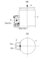
図1(a),(b),(c)は、本発明に係る真空排気装置の第1の態様を示す図であり、図1(a)は真空排気装置の部分断面正面図、図1(b)は真空排気装置の部分断面側面図、図1(c)は真空排気装置の部分断面底面図である。
図1(a),(b),(c)に示すように、本発明の真空排気装置は、高真空以下まで真空排気できる第一の真空ポンプ1と、大気圧から中真空又は低真空まで真空排気できる第二の真空ポンプ2とを備え大気圧力から超高真空領域まで排気する装置であって、第一の真空ポンプ1と第二の真空ポンプ2がユニット化されて一体の装置として構成されている。すなわち、第一の真空ポンプ1と第二の真空ポンプ2とは連結されて一体化されている。第一の真空ポンプ1はターボ分子ポンプからなり、第二の真空ポンプ2はドライ真空ポンプからなっている。第一の真空ポンプ1の排気口と第二の真空ポンプ2の吸気口は排気通路部品3によって接続されている。
Hereinafter, an embodiment of an evacuation apparatus according to the present invention will be described with reference to FIGS. 1 to 25, the same or corresponding components are denoted by the same reference numerals, and redundant description is omitted.
1 (a), (b), and (c) are views showing a first embodiment of the vacuum exhaust apparatus according to the present invention, and FIG. 1 (a) is a partial sectional front view of the vacuum exhaust apparatus, FIG. FIG. 1B is a partial cross-sectional side view of the vacuum exhaust apparatus, and FIG. 1C is a partial cross-sectional bottom view of the vacuum exhaust apparatus.
As shown in FIGS. 1 (a), (b), and (c), the vacuum evacuation device of the present invention includes a
通常、所定の容器内のガスを大気圧領域から超高真空領域まで排気する場合、始めに第二の真空ポンプとして容積式ポンプ(ドライポンプ)を使って中真空圧力まで排気した後に、第一の真空ポンプとしてターボ分子ポンプを起動して超高真空領域まで排気と言う段階を追って、排気動作が行われる。従来の方法では、中真空圧力までを担う第二の真空ポンプ(例えばドライポンプ)と、超高真空領域を担う第一の真空ポンプ(例えばターボ分子ポンプ)をそれぞれ用意し、一連の排気が可能なように配管で接続して排気システムを構築していた。しかしながら、このような方法ではドライポンプとターボ分子ポンプをつなぐ排気管の長さ・口径によって、同一の容器を排気する場合であっても、排気時間や排気に必要な動力の変動、或いはそれぞれポンプ自体の選定を変える必要がある等、設備計画の上で専門の知識が必要とされる場合がある。 Normally, when the gas in a given container is evacuated from the atmospheric pressure region to the ultra-high vacuum region, first, after evacuating to a medium vacuum pressure using a positive displacement pump (dry pump) as the second vacuum pump, The exhaust operation is performed following the stage of starting the turbo molecular pump as the vacuum pump and exhausting to the ultra-high vacuum region. In the conventional method, a second vacuum pump (for example, a dry pump) that handles medium vacuum pressure and a first vacuum pump (for example, a turbo molecular pump) that handles an ultra-high vacuum range are prepared, and a series of exhaust is possible. The exhaust system was constructed by connecting with piping. However, in such a method, even if the same container is exhausted depending on the length and diameter of the exhaust pipe connecting the dry pump and the turbo molecular pump, fluctuations in the exhaust time and power required for exhausting, Special knowledge may be required in equipment planning, such as the need to change the selection of itself.
本発明では、ターボ分子ポンプからなる第一の真空ポンプ1とドライ真空ポンプからなる第二の真空ポンプ2とを一体化してユニット化することで、ユーザは容器内の超高真空排気を1台のポンプシステムで構築・実施することが可能となり、且つターボ分子ポンプとドライ真空ポンプの組合せという構成を持つことで、中真空領域および超高真空領域でそれぞれのポンプが適切な消費動力を持って排気することが可能となる。したがって、本発明は、1つのポンプ方式、たとえば容積式真空ポンプで超高真空領域の排気、或いは運動量移送ポンプで大気領域の排気をするといったポンプとして排気効率が悪い運転状態に本質的にならないポンプを提供することが可能である。
In the present invention, the
上記「第一の真空ポンプ1と第二の真空ポンプ2を連結して一体化する」とは、第一の真空ポンプ1と第二の真空ポンプ2とを連結して一体化することにより、図1(a)に示すように物理的に一つのポンプユニットとすることである。この場合、真空排気装置のポンプ全体を一括して運転制御する制御装置を前記ユニットに取り付けて一体化してもよいし、前記ユニットの近傍に設置してもよい。
The above "connecting and integrating the
図1(a),(b),(c)に示すように、第二の真空ポンプ2は、スクリュー型ドライ真空ポンプから構成されており、ポンプケーシング内に一対のスクリューロータ52a,52bを備えている(後述する)。
As shown in FIGS. 1 (a), (b), and (c), the
図2は、図1に示す第一の真空ポンプ1の詳細構造を示す模式的断面図である。
図2に示すように、第一の真空ポンプ1を構成するターボ分子ポンプは、ポンプケーシング9内に吸気口側から排気口側に向かってタービン翼排気部10とねじ溝排気部20とを順次配置して構成されている。タービン翼排気部10は、多段の回転翼としてのタービン翼11と、タービン翼11の直後流に配置された多段の固定翼14とから構成されている。多段のタービン翼11は、概略円筒状のロータ12に一体に形成されており、ロータ12は回転軸13に固定されている。一方、多段の固定翼14は、ポンプケーシング9内に積層されたスペーサ15によって挟持されることによりポンプケーシング9に固定されている。これにより、タービン翼排気部10において、回転翼としてのタービン翼11と、固定翼14とが交互に配置される構成になっている。
FIG. 2 is a schematic cross-sectional view showing a detailed structure of the
As shown in FIG. 2, the turbo molecular pump constituting the
また、ねじ溝排気部20は、円筒状のロータ12の外周面に形成された円筒ねじ溝21と、円筒ねじ溝21の外周側に対向して配置された円筒状のねじ溝スペーサ22とから構成されている。ねじ溝スペーサ22はポンプケーシング9に固定されている。
前記ロータ12の内側にはステータ25が配置されており、ステータ25はポンプケーシング9の下部フランジ9lfに固定されている基部26と、基部26より上方に延びるスリーブ部27とを備えている。ステータ25のスリーブ部27には、回転軸13に回転駆動力を与えるモータと回転軸13を回転自在に支承する軸受とを有した軸受モータ部30が配置されている。
The thread
A
前記軸受モータ部30は、回転軸13に回転駆動力を与えるモータ31と、回転軸13をラジアル方向に支承する上ラジアル磁気軸受32,下ラジアル磁気軸受33と、排気部の排気作用による排気側と吸気側の差圧により生ずるスラスト力を打ち消す方向に作用するスラスト磁気軸受34を備えている。モータ31は高周波モータから構成されている。上ラジアル磁気軸受32,下ラジアル磁気軸受33,スラスト磁気軸受34は、いずれも能動型磁気軸受である。
The bearing
前記ポンプケーシング9の上端部には上部フランジ9ufが形成されており、上部フランジ9ufの内側が吸気口SPになっており、上部フランジ9ufに排気すべき真空容器(真空チャンバ)が接続される。また、ステータ25の基部26にはフランジ26fが形成されており、フランジ26fの内側が排気口DPになっている。フランジ26fに排気通路部品3(図1参照)が接続され、この排気通路部品3によってターボ分子ポンプからなる第一の真空ポンプ1は第二の真空ポンプ2に連通されるようになっている。
An upper flange 9uf is formed at the upper end of the
図3は、図1に示す第二の真空ポンプ2の詳細構造を示す模式的断面図である。図3に示すように、第二の真空ポンプ2はスクリュー型ドライ真空ポンプから構成されている。真空ポンプのポンプケーシング50内に2本の回転軸51a,51bが平行に並んで配置され、それぞれの回転軸51a,51bは軸受53により回転自在に支承されている。回転軸51aには右ねじ状の歯を有するスクリューロータ52aが固定され、回転軸51bには左ねじ状の歯を有するスクリューロータ52bが固定されている。スクリューロータ52a,52bは、回転軸51a,51bを支承する軸受53間に位置を合わせて並んで配置されている。
FIG. 3 is a schematic cross-sectional view showing a detailed structure of the
図3に示すように、スクリューロータ52a,52bの外周部とポンプケーシング50の内周面との間には微小なクリアランスが形成され、スクリューロータ52a,52bがポンプケーシング50内で非接触で回転可能となっている。また、スクリューロータ52a,52bの対向部には右ねじ状の歯と左ねじ状の歯が形成されており、スクリューロータ52a,52b同士は非接触で回転するようになっている。回転軸51a,51bの端部には一対のマグネットロータ54,54が固定されている。また、ポンプケーシング50の側面(図3の紙面と平行な面)には吸気口SPが設けられるとともに、排気口DPが設けられている。第二の真空ポンプ2の吸気口SPは排気通路部品3(図1参照)によって第一の真空ポンプ1の排気口DPに接続されている。一方の軸受53はポンプケーシング50に固定され、他方の軸受53は軸受ハウジング55及び軸受押さえ56に固定されている。軸受ハウジング55はポンプケーシング50に固定されており、軸受押さえ56は軸受ハウジング55に固定されている。
As shown in FIG. 3, a minute clearance is formed between the outer peripheral portions of the
図4は、図3のIV−IV線断面図である。図4に示すように、一対のマグネットロータ54,54は同一の構成を有し、平行に並んで配置されている。各マグネットロータ54は、磁性材のヨーク54bと、その外周面に取り付けられたリング形状のマグネット54aとを備えている。マグネット54aは8極に着磁しており、これにより、各マグネットロータ54の外周面には8極の磁極が形成されている。なお、マグネットロータ54の磁極数を8極としたが、この磁極数は偶数(2n:n=1,2,・・・)であれば良い。一対のマグネットロータ54,54は異磁極が引き合うように対向し、かつクリアランスCを保って配置されている。一対のスクリューロータ52a,52bは、一対のマグネットロータ54,54のマグネットカップリング作用により滑らかに反対方向に同期して回転することが可能になっている。また、一対のスクリューロータ52a,52bの同期して回転する力をさらに強めたい場合には、マグネットロータを一組のみならず複数組を回転軸51a,51bに取り付けてもよい。
4 is a cross-sectional view taken along line IV-IV in FIG. As shown in FIG. 4, the pair of
スクリュー型ドライ真空ポンプは、各マグネットロータ54の外周面の一部に近接して配置された鉄心57aと巻線57bとから成る三相(U,V,W)の電機子57による駆動方法を採用している。三相の電機子57はマグネットロータ54同士が対向する側とは反対側に2セット配置されている。このことはマグネットロータ54同士が互いに引き合う力をマグネットロータ54と鉄心57aとの間に作用する引力でキャンセルする狙いがある。なお、回転軸51a,51bを中心に配置された電機子57の各相の開角は60度となっている。
The screw-type dry vacuum pump has a driving method by a three-phase (U, V, W) armature 57 composed of an
三相の巻線57b(U1,V1,W1,U1′,V1′,W1′)は、一対のマグネットロータ54,54と一対の電機子57,57とにより2軸同期ブラシレス直流モータを構成する。巻線U1′,V1′,W1′は、それぞれ巻線U1,V1,W1と逆方向に巻かれている。マグネットロータ54の磁極位置に応じてiUV、iVW、iWU、iVU、iWV、iUWの6通りの通電を切り替えてマグネットロータ54を駆動する。
Three-phase winding 57b (U 1, V 1, W 1, U 1 ', V 1', W 1 ') is biaxially synchronized by a pair of
図3および図4に示すスクリュー型ドライ真空ポンプによれば、永久磁石と、永久磁石を回転させる巻線を備えた簡単な構成のモータで2軸のスクリューロータ52a,52bを反対方向に同期して回転させることができる。そのため、2軸のスクリューロータ52a,52bを同期させるタイミングギヤが不要で、オイルフリー、低振動・騒音を実現できるポンプである。軸受やタイミングギヤなどにオイルを用いていると、ポンプを傾けるとオイルが漏れてしまうため、ポンプの取付姿勢は限定されてしまうが、オイルフリーのためポンプの取付姿勢を自由に選択できる。また、タイミングギヤの接触に伴う振動・騒音が発生しない。
According to the screw-type dry vacuum pump shown in FIGS. 3 and 4, the two-
このような構造のドライポンプを第二の真空ポンプ2として用いることによって、第二の真空ポンプ2から第一の真空ポンプ1に伝わる振動を抑制することができ、第二の真空ポンプ2を第一の真空ポンプ1に連結して一体化することができる。第一の真空ポンプ1と第二の真空ポンプ2とを一体化する際に、第二の真空ポンプ2の取付姿勢を自由に選択することができる。そして、第一の真空ポンプ1と第二の真空ポンプ2とを一体化したユニットを真空容器(真空チャンバ)等の排気対象に取り付ける際に、一体化したユニットの取付姿勢を自由に選択することができる。
By using the dry pump having such a structure as the
次に、図3および図4に示すように構成された第二の真空ポンプ2を第一の真空ポンプ1に取り付ける際の取付姿勢について図1(a),(b),(c)を参照して説明する。図1(a),(b),(c)に示すように、第二の真空ポンプ2は、一対のスクリューロータ52a,52bが第一の真空ポンプ1の下面と平行な方向に並列するように取り付けられている。すなわち、第二の真空ポンプ2における一対のスクリューロータ52a,52bは、スクリューロータ52a,52bの軸心52ax,52bxが第一の真空ポンプ1の回転軸の軸心1xと直交し且つ第一の真空ポンプ1の下面から同一距離だけ離間して並列するように設定されている。
Next, refer to FIGS. 1A, 1B, and 1C for the mounting posture when mounting the
図5(a),(b),(c)は、第二の真空ポンプ2を第一の真空ポンプ1に取り付ける際の取付姿勢の他の例を示す図であり、図5(a)は真空排気装置の部分断面正面図、図5(b)は真空排気装置の部分断面側面図、図5(c)は真空排気装置の部分断面底面図である。
図5(a),(b),(c)に示すように、第二の真空ポンプ2は、一対のスクリューロータ52a,52bが第一の真空ポンプ1の下面に上下に並列するように取り付けられている。第二の真空ポンプ2における一対のスクリューロータ52a,52bは、スクリューロータ52a,52bの軸心2ax,2bxが第一の真空ポンプ1の回転軸の軸心1xと直交し且つ第一の真空ポンプ1の下面から上下に間隔をおいて並列するように設定されている。
FIGS. 5A, 5 </ b> B, and 5 </ b> C are diagrams illustrating another example of the mounting posture when the
As shown in FIGS. 5A, 5 </ b> B, and 5 </ b> C, the
図1および図5に示す真空排気装置は、ターボ分子ポンプからなる第一の真空ポンプ1とドライ真空ポンプからなる第二の真空ポンプ2とを一体化してユニット化する際、第二の真空ポンプ2の回転軸の軸心と第一の真空ポンプ1の回転軸の軸心とを直交する方向に配置した真空排気装置である。
When the vacuum pumping apparatus shown in FIG. 1 and FIG. 5 integrates the
ドライ真空ポンプとターボ分子ポンプでは、それぞれで運転中に発生する振動の方向性の傾向には、すなわち振動エネルギーの大きい方向には、大きな差異はなく、それぞれ回転軸のラジアル方向に回転体のアンバランスに起因する振動が発生する。もし、本発明のユニット化された真空排気装置において、ターボ分子ポンプの回転軸とドライ真空ポンプの回転軸を平行(直列)に配置した場合、極めて少ない確率ではあるが、回転軸の軸心と直交する方向(ラジアル方向)に発生する回転振動が、ドライポンプとターボ分子ポンプで同時に発生し、共振振動などの発生する可能性がある。また、ラジアル方向の振動が重ね合わされ、過大な振動として真空容器側へ伝わってしまう。このため、本発明では、ドライ真空ポンプの回転軸の軸心とターボ分子ポンプの回転軸の軸心とは、互いに直交方向に配置することで、真空容器側へ取り付けられる第一の真空ポンプ1の回転軸のラジアル方向振動成分を抑える構造としている。
In the dry vacuum pump and the turbo molecular pump, there is no significant difference in the directionality of vibration generated during operation, that is, in the direction where the vibration energy is large, and the rotating body unwinds in the radial direction of the rotating shaft. Vibration due to balance occurs. If the rotating shaft of the turbo molecular pump and the rotating shaft of the dry vacuum pump are arranged in parallel (in series) in the unitized vacuum exhaust apparatus of the present invention, the shaft center of the rotating shaft is Rotational vibration generated in the orthogonal direction (radial direction) may occur simultaneously in the dry pump and the turbo molecular pump, and resonance vibration may occur. Moreover, radial vibrations are superimposed and transmitted to the vacuum container as excessive vibrations. For this reason, in the present invention, the
第一の真空ポンプで一般的に用いられるターボ分子ポンプは、上述したように取り付け姿勢が自由であり、真空容器の周辺に任意の方向で取り付けることができるため、真空容器周りの設計の自由度に大きく寄与している。本発明の真空排気装置は、その特徴を維持できるものとなるが、2台のポンプをユニット化する際、真空容器に直接取り付けられる側の第一の真空ポンプ1の軸心1xと、ユニット化された真空排気装置の重心位置が合うようにしている。これによって、例えば、真空排気装置を横置きに設置する場合など、第一の真空ポンプ1の軸心1xに対しねじりモーメントが発生せず、真空排気装置を取り付ける真空容器側の変形が単純化する、もしくは設置方法が簡易化する。また、発生する振動もねじり方向の振動などは発生せず、振動抑制を図り易い。真空排気装置は、真空容器の近傍に設置もしくは真空容器に直接接続するので、振動の抑制は重要である。
The turbo molecular pump generally used in the first vacuum pump has a free mounting posture as described above, and can be mounted in any direction around the vacuum container. It contributes greatly to. The vacuum evacuation device of the present invention can maintain the characteristics, but when the two pumps are unitized, the
前記第一の真空ポンプ1の回転軸を支持する軸受及び第二の真空ポンプ2の回転軸を支持する軸受は、自己潤滑性がある材料或は軌道内にグリスなどを内包した転がり軸受、或は自己潤滑性のあるジャーナル軸受、或は気体軸受もしくは磁気軸受などの非接触軸受の何れかを使用しており、設置方向がいずれの方向であっても回転軸が健全な状態で回転維持することが可能になっている。本発明の真空排気装置は、外観上は1つにまとめられたポンプユニットであるため、内部にドライ真空ポンプとターボ分子ポンプとが組み合わされていることをユーザが意識することはない。一般的なドライ真空ポンプは、鉱物油などの粘度が低い潤滑油を軸受部に使用するため、ポンプ自体の取付方向にある程度の制約がある。これに対して、ターボ分子ポンプはグリスを主体とした潤滑油を使ったボールベアリング或いは非接触軸受を使って回転体を支えているため、取付方向には特段の制約がない。本発明のドライ真空ポンプは、鉱物油など粘度が低い潤滑油を軸受部に使用することなく、回転体を支えることが可能な軸受を使用することで、ポンプユニットとして取付方向に特段の制約が発生しない構造としている。
The bearing that supports the rotating shaft of the
次に、ポンプ全体を一括して運転制御する制御装置について説明する。第一の真空ポンプ1と第二の真空ポンプ2の2つのポンプは別々の駆動系(モータ)を有しているが、例えばモータ駆動電源仕様を統一し、一つの箱内に収めることにより部品の共通化が図られ、制御装置を別々に分けるよりも小容積化、および低コスト化が図れる。制御装置は第一の真空ポンプ側に設置した方が望ましい。ターボ分子ポンプに比べてドライポンプは、大気圧までの圧縮に伴う圧縮熱の発生により、高温となっている。また、ターボ分子ポンプの振動レベルは容積式のドライポンプに比べて非常に小さい。そのため、精密電子部品を多数搭載している制御装置はドライポンプではなく、ターボ分子ポンプ側に設置した方が、熱・振動影響を受け難く、ユニット全体の信頼性が向上する。
Next, a description will be given of a control device that collectively controls the operation of the entire pump. The two pumps, the
図6(a),(b)は、第一の真空ポンプ1に制御装置4を設置した真空排気装置を示す正面図である。
図6(a)に示す例においては、制御装置4は第一の真空ポンプ1の外周面に取り付けられている。
図6(b)に示す例においては、制御装置4は第一の真空ポンプ1の下面に取り付けられている。なお、制御装置4を第一の真空ポンプ1に取り付ける取付部に防振機構を設けてもよい。防振機構としては、防振ゴム(天然ゴム、二トリルゴム、シリコンゴム、フッ素ゴムなど)、バネなどが考えられる。
図6(a),(b)に示す実施形態においては、制御装置4が第一の真空ポンプ(ターボ分子ポンプ)側に設置された例を挙げたが、制御装置をポンプ側から離して設置する方がよい場合は、その選択は任意である。
FIGS. 6A and 6B are front views showing a vacuum exhaust apparatus in which the
In the example shown in FIG. 6A, the
In the example shown in FIG. 6B, the
In the embodiment shown in FIGS. 6A and 6B, an example in which the
図7(a),(b)は、第一の真空ポンプ1の底面部品と第二の真空ポンプ2のポンプケーシングとを一体化した態様を示す模式的断面図である。
図7(a)に示す例においては、第一の真空ポンプ1の底面部品40と第二の真空ポンプ2のポンプケーシング50とを一体化部品60として構成している。
図7(b)に示す例においては、第一の真空ポンプ1の底面部品40と第二の真空ポンプ2のポンプケーシング50とを一体化部品60として構成し、さらにこの一体化部品60に第一の真空ポンプ1と第二の真空ポンプ2とを連通させる排気通路3aを取り込むようにしている。
7A and 7B are schematic cross-sectional views showing an aspect in which the bottom part of the
In the example shown in FIG. 7A, the
In the example shown in FIG. 7 (b), the
図7(a),(b)に示すように、底面部品40とポンプケーシング50とを共通化することにより、部品点数削減(低コスト化)およびユニット全体の省容積化を図ることができる。また、図7(b)に示すように、一体化部品60に2台のポンプの排気通路3aを取り込んでしまうこともできる。2台のポンプの排気経路を短くできれば、コンダクタンスが大きくなり、第二の真空ポンプ2の低容量化に繋がる。そうすると、ユニット全体での更なる低コスト化、小容積化を図ることができる。また、底面部品40とポンプケーシング50とを一体化したことにより2台のポンプの熱伝導性が向上する。大気圧までの圧縮を行う第二の真空ポンプ2は、超高真空側の第一の真空ポンプ1に比べて消費電力が大きく発熱量も多い。第二の真空ポンプ2が冷却水を用いる仕様の場合は、2台のポンプ間の熱伝導性を高めておけば、第二の真空ポンプ2に設置されている冷却機構のみで、効率よく2台のポンプの冷却(放熱)を行うことができる。
As shown in FIGS. 7A and 7B, by sharing the
第二の真空ポンプ2の冷却に冷却水を用いない場合には、第一の真空ポンプ1と第二の真空ポンプ2の締結面間の熱伝導性を悪くするために、前記締結部に断熱部材を設ける、もしくは締結部接触断面積を小さくする、もしくはその両方を実施することも有効である。第二の真空ポンプの冷却に冷却水を用いない場合、放熱方法は強制空冷となる。先にも述べたが、大気圧までの圧縮を行う第二の真空ポンプは、超高真空側の第一の真空ポンプに比べ消費電力が大きく発熱量も多い。冷却水にて効率よく排熱できる仕様に比べ、強制空冷での排熱性能は劣り、その分、2台のポンプ間の熱伝導性が良い場合、第二の真空ポンプからの発熱量が第一の真空ポンプ側へある程度伝導することが考えられ、場合によっては第一の真空ポンプの運転に支障を来たす可能性が考えられる。そこで、2台のポンプ間の熱伝導を悪くし、第二の真空ポンプ2から第一の真空ポンプ1への熱伝導を極力抑える。そして、第二の真空ポンプの断面積に合わせた空冷ファンなどを用い、局所的に排熱する。第二の真空ポンプからの発熱が第一の真空ポンプへ伝導し、第一の真空ポンプ、第二の真空ポンプ両方を空冷しなければならない場合、空気の流れが効率よく2台のポンプに行き渡るようにファンの設置、空気の流れを導くダクト(カバー)などの設計・設置が必要となる。しかし、第二の真空ポンプのみの局所空冷の場合、それらが簡便化する。断熱部材として、セラミックス(アルミナ、イットリア、ジルコニア)、ステンレス合金、プラスチック(PEEK,PTFE)などが考えられる。
When cooling water is not used for cooling the
図8は、第一の真空ポンプ1と第二の真空ポンプ2の締結面間に防振機構61を設けた態様を示す模式図である。本発明においては、第二の真空ポンプ2は一対のスクリューロータがマグネットカップリング作用により同期回転するように構成しているため、2軸のスクリューロータを同期させるタイミングギヤが不要であり、第二の真空ポンプ2の振動を飛躍的に低減できる。それでも、大気圧まで圧縮排気している第二の真空ポンプ2の振動は、ターボ分子ポンプからなる第一の真空ポンプ1に比べて大きい。そのため、図8に示すように、第二の真空ポンプ2からの振動を防振する防振機構61を2台のポンプの締結部に設けることにより、第一の真空ポンプ1へ伝わる振動レベルをさらに低減することができる。防振機構61としては、防振ゴム(天然ゴム、二トリルゴム、シリコンゴム、フッ素ゴムなど)、バネなどが考えられる。
FIG. 8 is a schematic view showing an aspect in which a
また、図8に示す真空排気装置においては、第一の真空ポンプ1の排気口と第二の真空ポンプ2の吸気口とを接続する排気通路部品3は、防振材料で構成されている。排気通路部品3が剛性の高い材料、構造の場合、その部品より振動が伝導してしまう恐れもある。排気通路部品3を防振作用のある材料で成形することにより、第二の真空ポンプ2から第一の真空ポンプ1へ伝播してくる振動を抑えることができる。防振材料としては、天然ゴム、二トリルゴム、シリコンゴム、フッ素ゴムなどのゴム材を用い、チューブ状、もしくはブロック状に成形してもよい。排気通路部品3がゴム等の防振材料部品で構成されている場合、その内部が真空になったときに大気との差圧力により変形してしまう。変形具合は、部品の材質、形状により差はあるが、変形抑制として、内部に金属製のコイルバネを入れてもよい。バネであれば、真空接続している防振材料部品として、曲げたりすることを妨げない。また防振材料部品の長さに対し、どのくらいの長さのコイルバネを入れるかも任意で決めてよい。
Further, in the vacuum exhaust apparatus shown in FIG. 8, the
図9は、第一の真空ポンプ1と第二の真空ポンプ2とを締結する締結部品に防振機構を設けた態様を示す概略図である。図9に示すように、第一の真空ポンプ1と第二の真空ポンプ2との間には、締結部品62が設置されている。締結部品62には複数の防振ブッシュ63が取り付けられており、防振ブッシュ63に固定用ボルト64を挿通して固定用ボルト64を第一の真空ポンプ1に螺合することにより、締結部品62は防振ブッシュ63を介して第一の真空ポンプ1に固定されている。
また、締結部品62には、第二の真空ポンプ2の吸気口SPと連通する排気通路62aが形成されるとともに第二の真空ポンプ2の排気口DPと連通する排気通路62bが形成されている。締結部品62の排気通路62aは排気通路部品3により第一の真空ポンプ1の排気口DP(図2参照)に接続されている。締結部品62の排気通路62bは真空ポンプ2の排気口DPを大気に連通させるようになっている。排気通路部品3はゴム材等からなる防振材料部品により構成されている。
FIG. 9 is a schematic view showing an aspect in which a vibration isolation mechanism is provided in a fastening part that fastens the
Further, the
図10(a),(b),(c)は、図9に示す締結部品62および防振ブッシュ63からなる締結部の詳細構造を示す図であり、図10(a)は締結部の断面図、図10(b)は締結部の底面図、図10(c)は防振ブッシュ63の分解斜視図である。
図10(a),(b)に示すように、締結部品62には複数の貫通孔62hが設けられており、これら貫通孔62hの内周壁には半径方向内方に突出するフランジ部62f(図10(a))が形成されている。図10(c)に示すように、防振ブッシュ63は、大径のリング状部と小径のリング状部とからなる上部部材63aとリング状部材からなる下部部材63bとから構成されている。図10(a)に示すように、上部部材63aは、小径のリング状部が締結部品62のフランジ部62fの内周面に嵌合されるとともに大径のリング状部の下面がフランジ部62fの上面に当接することにより、締結部品62に装着される。下部部材63bは、上部部材63aの小径のリング状部の外周面に嵌合されるとともにフランジ部62fの下面に当接している。上部部材63aと下部部材63bの嵌合部は接着剤等により一体化することにより、上部部材63aと下部部材63bとにより締結部品62のフランジ部62fを挟持する。これにより、防振ブッシュ63は締結部品62に取り付けられる。その後、防振ブッシュ63に固定用ボルト64を挿通するとともにボルト頭部と防振ブッシュ63との間に座金65を介装して固定用ボルト64を第一の真空ポンプ1に締め込むことにより、締結部品62は防振ブッシュ63を介して第一の真空ポンプ1に固定される。また、締結部品62と第二の真空ポンプ2とはボルト等によって固定される。
FIGS. 10A, 10B, and 10C are views showing a detailed structure of a fastening portion including the
As shown in FIGS. 10 (a) and 10 (b), the
本発明によれば、図10(a),(b),(c)に示すように、複数の防振ブッシュ63からなる防振機構を用いて第一の真空ポンプ1と第二の真空ポンプ2とを締結することにより、第二の真空ポンプ2から第一の真空ポンプ1へ伝わる振動レベルを低減することができる。
According to the present invention, as shown in FIGS. 10A, 10 </ b> B, and 10 </ b> C, the
図11(a),(b)は、真空容器(真空チャンバ)5に第一の真空ポンプ1と第二の真空ポンプ2とを一体化したポンプユニット(真空排気装置)を取り付ける場合の実施例を示す正面図である。図11(a),(b)に示す実施例においては、図1に示すユニット(真空排気装置)の真空容器への取り付け例を示す。
図11(a)に示す実施例においては、第一の真空ポンプ1と第二の真空ポンプ2とを一体化したポンプユニットは、真空容器5の下方に取り付けられており、第一の真空ポンプ1の軸心が垂直方向になるように配置されている。第二の真空ポンプ2のスクリューロータ52a,52bの軸心と第一の真空ポンプ1の軸心とは直交している。
図11(b)に示す実施例においては、第一の真空ポンプ1と第二の真空ポンプ2とを一体化したポンプユニットは、真空容器5の側方に取り付けられており、第一の真空ポンプ1の軸心が水平方向になるように配置されている。第二の真空ポンプ2のスクリューロータ52a,52bの軸心と第一の真空ポンプ1の軸心とは直交している。
なお、第一の真空ポンプ1と第二の真空ポンプ2とを一体化したユニットを真空容器5の上方に取り付けてもよい。また、図5に示すように第一の真空ポンプ1と第二の真空ポンプ2とを一体化したポンプユニットも図11(a),(b)と同様の取付姿勢で真空容器5に取り付けることができる。
FIGS. 11A and 11B show an embodiment in which a pump unit (evacuation device) in which a
In the embodiment shown in FIG. 11A, the pump unit in which the
In the embodiment shown in FIG. 11B, the pump unit in which the
A unit in which the
次に、第二の真空ポンプ2を第一の真空ポンプ1に取り付ける際の取付姿勢についてさらに説明する。
図12(a),(b)は、第二の真空ポンプ2を第一の真空ポンプ1の側面に取り付けた取付姿勢を示す図であり、図12(a)は部分断面正面図、図12(b)は底面図である。
図12(a),(b)に示すように、第二の真空ポンプ2は第一の真空ポンプ1の側面に取り付けられている。すなわち、第一の真空ポンプ1の円筒状のポンプケーシングの外側面を平坦に切り欠いて、平坦面に第二の真空ポンプ2が固定されている。図12(a),(b)に示す例においては、第一の真空ポンプ1の軸心1xと第二の真空ポンプ2のスクリューロータ52a,52bの軸心52ax,52bxとが平行に配置されている。図1および図5に示す例においては、第一の真空ポンプ1の回転軸と第二の真空ポンプ2の回転軸とを直交させてラジアル方向の共振振動を避けるようにしたが、本発明においては、第二の真空ポンプ2は一対のスクリューロータがマグネットカップリング作用により同期回転するように構成しているため、2軸のスクリューロータを同期させるタイミングギヤが不要であり、第二の真空ポンプ2の振動を飛躍的に低減できる。そのため、第一の真空ポンプ1の回転軸と第二の真空ポンプ2の回転軸とを平行に配置しても、ラジアル方向の共振振動が発生する恐れはない。
Next, the attachment posture when attaching the
12 (a) and 12 (b) are views showing a mounting posture in which the
As shown in FIGS. 12A and 12B, the
図13(a),(b),(c)は、第二の真空ポンプ2を第一の真空ポンプ1の側面に取り付け、第一の真空ポンプ1と第二の真空ポンプ2とを締結する締結部品に防振機構を設けた例を示す図であり、図13(a)は部分断面正面図、図13(b)は部分断面底面図、図13(c)は締結部の詳細構造を示す断面図である。
図13(a),(b)に示すように、第二の真空ポンプ2は第一の真空ポンプ1の側面に取り付けられ、第一の真空ポンプ1と第二の真空ポンプ2との間には、締結部品62が設置されている。締結部品62には複数の防振ブッシュ63が取り付けられており、防振ブッシュ63に固定用ボルト64を挿通して固定用ボルト64を第一の真空ポンプ1に螺合することにより、締結部品62は防振ブッシュ63を介して第一の真空ポンプ1に固定されている。
図13(c)に示すように、締結部品62,防振ブッシュ63,固定用ボルト64および座金65は、図10(a),(b),(c)に示すものと同様の構成であり、取付方法も同様である。
13A, 13B, and 13C, the
As shown in FIGS. 13 (a) and 13 (b), the
As shown in FIG. 13 (c), the
図14は、第一の真空ポンプ1の排気口と第二の真空ポンプ2の吸気口とを接続する排気通路部品3に逆流防止弁を設けた態様を示す模式図である。図14に示すように、第一の真空ポンプ1と第二の真空ポンプ2とを一体化したポンプユニットは真空容器5に取り付けられている。第一の真空ポンプ1の排気口と第二の真空ポンプ2の吸気口とを接続する排気通路部品3には逆流防止弁6が設置されている。
本発明は、ターボ分子ポンプからなる第一の真空ポンプ1とドライポンプからなる第二の真空ポンプ2間の排気流路も含めて第一の真空ポンプ1と第二の真空ポンプ2とを一体化したポンプ構成であるため、流路の圧力条件が既知であり、各ポンプの運転状態に異常が発生したとき、たとえば排気側ドライポンプの故障によりターボ分子ポンプの背圧が急上昇した場合に、排気通路部品3の内部の所定の圧力差でそれ自身が自動的に閉止する構造を持った逆流防止弁6を設置することでターボ分子ポンプの排気側の圧力急上昇を防止することが可能となる。
FIG. 14 is a schematic view showing a mode in which a backflow prevention valve is provided in the
In the present invention, the
図15は、第一の真空ポンプ1の吸気口と第二の真空ポンプ2の吸気口とを接続して第一の真空ポンプ1をバイパスさせるバイパス配管を設けた態様を示す模式図である。図15に示すように、第一の真空ポンプ1の吸気口と第二の真空ポンプ2の吸気口とを接続するバイパス配管7が設置されている。バイパス配管7を設けることにより、第一の真空ポンプの吸気口から第二の真空ポンプの吸気口へ直接排気を行うことで、第一の真空ポンプをバイパスさせることが可能であり、真空容器5の真空破壊が発生した場合でも第一の真空ポンプ1への急激な負荷増加による回転体の破損を防止することができる。
FIG. 15 is a schematic view showing an aspect in which a bypass pipe is provided to connect the intake port of the
また、バイパス配管7には、真空容器側の圧力が急上昇した場合に、第二の真空ポンプ2へ直接流路をあけるバイパスバルブ8を設けている。バイパスバルブ8は、配管の圧力条件で、それ自身が自動的に開閉する構造を持ったバイパスバルブである。この条件は、ターボ分子ポンプからなる第一の真空ポンプ1とドライポンプからなる第二の真空ポンプ2を一体化してユニット化した本発明において、両ポンプ間の流路配管も最適な条件で構成することができるために、実現可能である。
Further, the
上述した実施形態においては、第二の真空ポンプとしてスクリュー型ドライポンプを例に挙げて説明したが、第二の真空ポンプとしてはルーツ型ドライポンプ、ダイヤフラムポンプ、スクロール式ポンプなどを用いてもよい。ただし、ダイヤフラムポンプは薄膜の上下運動による容積変化により気体を移送する排気原理のポンプであるため、第二の真空ポンプがダイヤフラムポンプの場合、真空排気装置全体での振動低減を考えると、ダイヤフラムポンプの上下移動方向(振動方向)と第一の真空ポンプの軸方向が平行であることが望ましい。 In the above-described embodiment, the screw type dry pump has been described as an example of the second vacuum pump. However, a roots type dry pump, a diaphragm pump, a scroll pump, or the like may be used as the second vacuum pump. . However, since the diaphragm pump is a pump based on the exhaust principle that transfers gas by volume change due to the vertical movement of the thin film, when the second vacuum pump is a diaphragm pump, considering the vibration reduction in the entire vacuum exhaust device, the diaphragm pump The vertical movement direction (vibration direction) of the first vacuum pump and the axial direction of the first vacuum pump are preferably parallel.
次に、第一の真空ポンプ1および第二の真空ポンプ2を制御する制御装置の制御方法について説明する。
(1)通常、ポンプの排気速度調整を行なう場合は、吸気側開口面積を、バルブなどを使って調整することにより行なう。それに対し、本発明では真空容器内圧力の制御を、真空容器とポンプ間に備えられたバルブの開度調整(開口面積調整)で行うのではなく、第一の真空ポンプ1もしくは第二の真空ポンプ2のいずれか或いはその両方のポンプ回転数(ポンプ回転速度)を制御することで、真空ポンプそれぞれの排気速度を調整し、ポンプシステム全体の排気速度を調整することを可能としている。すなわち、ポンプ以外の制御用バルブなどの機器を使用することなく、真空容器内圧力を調整することが、当該ポンプシステム1台で実現することが可能である。
Next, a control method of a control device that controls the
(1) Normally, when adjusting the pumping speed of the pump, the suction side opening area is adjusted by using a valve or the like. On the other hand, in the present invention, the pressure in the vacuum vessel is not controlled by adjusting the opening of the valve provided between the vacuum vessel and the pump (opening area adjustment), but the
(2)図16は、第一の真空ポンプをターボ分子ポンプ、第二の真空ポンプをドライポンプで構成しながら、容器内の圧力調整を調整する方法として、各ポンプの回転速度制御を行った場合の回転速度(回転数)と圧力の変化について本発明の真空排気装置と従来の真空排気装置とを比較したグラフである。
本発明の真空排気装置のように、第一の真空ポンプ(ターボ分子ポンプ)と第二の真空ポンプ(ドライポンプ)間の配管が非常に短い距離で設置されている場合、圧力調整を開始してから第一の真空ポンプの回転数を下げ、真空容器の圧力が所定の条件に至った時点(第二の真空ポンプ減速開始点)で第二の真空ポンプの減速を開始させる。両ポンプを繋ぐ配管長が短いため、第二の真空ポンプの減速に対する真空容器の圧力変化が速く、その結果、目標の真空容器圧力(圧力調整完了点)に最短の時間で到達することができる。しかしながら、従来の真空排気装置のように、第一の真空ポンプと第二の真空ポンプ間の配管が長い場合、第二の真空ポンプの減速に対する真空容器の圧力変化に遅れが生じるため、目標の真空容器圧力(圧力調整完了点)に到達するのに時間を要することとなる。
(2) In FIG. 16, the rotational speed of each pump was controlled as a method of adjusting the pressure adjustment in the container while the first vacuum pump was a turbo molecular pump and the second vacuum pump was a dry pump. It is the graph which compared the vacuum evacuation device of this invention with the conventional vacuum evacuation device about the rotation speed (rotation speed) and pressure change in the case.
When the piping between the first vacuum pump (turbo molecular pump) and the second vacuum pump (dry pump) is installed at a very short distance as in the vacuum exhaust apparatus of the present invention, pressure adjustment is started. After that, the number of rotations of the first vacuum pump is lowered, and the second vacuum pump is started to decelerate when the pressure in the vacuum vessel reaches a predetermined condition (second vacuum pump deceleration start point). Since the length of the pipe connecting the two pumps is short, the pressure change of the vacuum vessel with respect to the deceleration of the second vacuum pump is fast, and as a result, the target vacuum vessel pressure (pressure adjustment completion point) can be reached in the shortest time. . However, when the piping between the first vacuum pump and the second vacuum pump is long as in the conventional vacuum evacuation device, a delay occurs in the pressure change of the vacuum vessel with respect to the deceleration of the second vacuum pump. It takes time to reach the vacuum vessel pressure (pressure adjustment completion point).
第一の真空ポンプ1と第二の真空ポンプ2とを連結して一体化して一つのポンプシステムを構築する際に、第一の真空ポンプ1に第二の真空ポンプ2を取り付けることが望ましい。そのため、第二の真空ポンプ2の外形寸法は、第一の真空ポンプ1の外形寸法より小さいことが望ましい。
次に、第一の真空ポンプ1および第二の真空ポンプ2の外形寸法について具体的数値を挙げて説明する。以下に記す寸法には、電装系(ドライバ,コントローラ,空冷ファンなど)は含まず、ポンプ排気部と駆動部(モータ)のみを含むものである。
(1)本発明の第二の真空ポンプに、2軸容積移送式ポンプ(スクリュー型ロータ)でマグネットカップリングモータを使用した場合、第二真空ポンプ到達性能:400Pa以下

第一真空ポンプを1とした場合の第二真空ポンプの概略軸方向寸法比:1〜0.7
第一真空ポンプを1とした場合の第二真空ポンプの概略容積比:0.4
第一真空ポンプを1とした場合の第二真空ポンプの概略軸方向寸法比:0.8〜0.6
第一真空ポンプを1とした場合の第二真空ポンプの概略容積比:0.4
(2)上記組合せで使用できる第二の真空ポンプで、ダイヤフラム型ポンプの場合の例
第二真空ポンプ到達性能:400Pa以下
第一真空ポンプを1とした場合の第二真空ポンプの概略軸方向寸法比:1.8〜1.3
第一真空ポンプを1とした場合の第二真空ポンプの概略容積比:1
第一真空ポンプを1とした場合の第二真空ポンプの概略軸方向寸法比:1.7〜1.4
第一真空ポンプを1とした場合の第二真空ポンプの概略容積比:2.6
When the
Next, the external dimensions of the
(1) When a magnetic coupling motor is used for the second vacuum pump of the present invention with a biaxial displacement pump (screw type rotor), the second vacuum pump performance: 400 Pa or less
Schematic axial dimension ratio of the second vacuum pump when the first vacuum pump is 1: 1 to 0.7
Approximate volume ratio of the second vacuum pump when the first vacuum pump is 1: 0.4
Schematic axial dimension ratio of the second vacuum pump when the first vacuum pump is 1: 0.8 to 0.6
Approximate volume ratio of the second vacuum pump when the first vacuum pump is 1: 0.4
(2) Example of diaphragm pump with the second vacuum pump that can be used in the above combination Second vacuum pump reachability: 400 Pa or less
Schematic axial dimension ratio of the second vacuum pump when the first vacuum pump is 1: 1.8 to 1.3
When the first vacuum pump is 1, the approximate volume ratio of the second vacuum pump is 1
Schematic axial dimension ratio of the second vacuum pump when the first vacuum pump is 1: 1.7 to 1.4
Approximate volume ratio of the second vacuum pump when the first vacuum pump is 1: 2.6
上記比較結果から分かるように、本発明の第一の真空ポンプにターボ分子ポンプを使用し、本発明の第二の真空ポンプに2軸容積移送式ポンプ(スクリュー型ロータ)で、マグネットカップリングモータを使用した場合、第一の真空ポンプの容積に対して第二の真空ポンプの容積を小さくできるため、第二の真空ポンプを第一の真空ポンプに取り付けるに際して取付姿勢に制約を受けることがない。
また、第一の真空ポンプと第二の真空ポンプとに上記組合せを採用することにより、第二の真空ポンプの数倍の排気容量がある1台の第一の真空ポンプに対して複数台の第二の真空ポンプを一体化することも可能である。
As can be seen from the above comparison results, a turbo molecular pump is used for the first vacuum pump of the present invention, a biaxial volume transfer pump (screw type rotor) is used for the second vacuum pump of the present invention, and a magnet coupling motor. Since the volume of the second vacuum pump can be made smaller than the volume of the first vacuum pump, the mounting posture is not restricted when the second vacuum pump is attached to the first vacuum pump. .
Further, by adopting the above combination for the first vacuum pump and the second vacuum pump, a plurality of units can be provided for one first vacuum pump having an exhaust capacity several times that of the second vacuum pump. It is also possible to integrate the second vacuum pump.
図17は、1台の第一の真空ポンプ1に対して複数台の第二の真空ポンプ2を一体化した真空排気装置の実施形態を示す概略図である。図17に示すように、1台の第一の真空ポンプ1に2台の第二の真空ポンプ2が連結されて一体化されている。第一の真空ポンプ1の排気口と2台の第二の真空ポンプ2の吸気口とは、個別に排気通路部品3により接続されている。このように、1台の第一の真空ポンプ1に対して複数台の第二の真空ポンプ2を一体化することにより、第一の真空ポンプ1の排気容量に適合した排気容量を持った粗挽きポンプを構築することが可能となる。
FIG. 17 is a schematic view showing an embodiment of a vacuum exhaust apparatus in which a plurality of
図18は、1台の第一の真空ポンプ1に対して複数台の第二の真空ポンプ2を吸排気経路で連結し一体化した真空排気装置の実施形態を示す概略図である。図18に示すように、1台の第一の真空ポンプ1に2台の第二の真空ポンプ2が連結されて一体化されている。一体化されたポンプユニットは、真空容器5の下方に取り付けられている。1台の第一の真空ポンプ1の排気口と2台の第二の真空ポンプ2の吸気口とは、排気通路部品3により接続されている。このように、1台の第一の真空ポンプ1に対して複数台の第二の真空ポンプ2を一体化することにより、第一の真空ポンプ1の排気容量に適合した排気容量を持った粗挽きポンプを構築することが可能となる。
1台の第一の真空ポンプ1に対し、第二の真空ポンプ2を2台並列に接続することで、第二の真空ポンプ全体としては排気性能を2倍にすることが可能であるとともに、真空容器内の圧力制御を行う際、1台の第二の真空ポンプで行うべき調圧制御を2台の並列した第二の真空ポンプで制御することで圧力制御をより細かく制御することができる。また短時間での制御が可能になる。
さらに、第二の真空ポンプが1台の場合には、第二の真空ポンプが停止すると第一の真空ポンプも運転を継続することができなくなり停止し、その結果、真空容器内圧力が急上昇してしまう。しかし、第二の真空ポンプが2台の場合には、仮に第二の真空ポンプのうち1台のポンプが停止しても、もう一方の第二の真空ポンプにより、第一の真空ポンプの排気口圧力を許容圧力以下にすることができる。したがって第一の真空ポンプが停止して真空容器内の圧力が急上昇するような事態を回避することができる。
FIG. 18 is a schematic view showing an embodiment of a vacuum exhaust apparatus in which a plurality of
By connecting two
Furthermore, when there is one second vacuum pump, when the second vacuum pump is stopped, the first vacuum pump cannot be continued to operate, and as a result, the pressure in the vacuum vessel rapidly rises. End up. However, if there are two second vacuum pumps, even if one of the second vacuum pumps stops, the other second vacuum pump causes the first vacuum pump to evacuate. The mouth pressure can be made lower than the allowable pressure. Therefore, it is possible to avoid a situation in which the first vacuum pump is stopped and the pressure in the vacuum vessel rapidly increases.
図19は、複数台の第一の真空ポンプ1と1台の第二の真空ポンプ2とを吸排気経路で連結し一体化した真空排気装置の実施形態を示す概略図である。図19に示すように、2台の第一の真空ポンプ1と1台の第二の真空ポンプ2とが連結されて一体化されている。一体化されたポンプユニットは、真空容器5の下方に取り付けられている。2台の第一の真空ポンプ1の排気口と1台の第二の真空ポンプ2の吸気口とは、排気通路部品3により接続されている。このように、複数台の第一の真空ポンプ1と1台の第二の真空ポンプ2とを一体化することにより、第一の真空ポンプ1を小型化することができる。
図19に示すように第一の真空ポンプを2台並列に接続し、第二の真空ポンプを1台として一体に構成する場合には、第一の真空ポンプの排気性能を大きくするために高速回転するポンプロータを大型化することなく、安全な真空排気システムを構成することができる。
FIG. 19 is a schematic view showing an embodiment of a vacuum exhaust apparatus in which a plurality of
When two first vacuum pumps are connected in parallel as shown in FIG. 19 and the second vacuum pump is integrated as a single unit, a high speed is used to increase the exhaust performance of the first vacuum pump. A safe evacuation system can be configured without increasing the size of the rotating pump rotor.
図20は、2台の第一の真空ポンプと1台の第二の真空ポンプとを連結し一体化した真空排気装置の制御回路図である。図20に示すように、2台の第一の真空ポンプ用のモータおよびインバータは、TMP1用モータ,TMP2用モータおよびTMP1用INV,TMP2用INVで示され、1台の第二の真空ポンプ用のモータおよびインバータは、DRY用モータおよびDDY用INVで示されている。この回路図に示されるように1つの制御装置(CPU)で3台のインバータTMP1用INV,TMP2用INV,DRY用INVを一体的に制御することが可能となる。すなわち、各真空ポンプの吸排気配管内に圧力検出器などを設置することなく、所定の回転数制御レートで各真空ポンプのモータ回転数を制御することにより真空容器内の圧力を最適に制御することが可能となる。図20においてPFCは力率改善回路、DC/DCはDC/DCコンバータである。 FIG. 20 is a control circuit diagram of a vacuum exhaust apparatus in which two first vacuum pumps and one second vacuum pump are connected and integrated. As shown in FIG. 20, the motors and inverters for the two first vacuum pumps are indicated by the motor for TMP1, the motor for TMP2, the INV for TMP1, and the INV for TMP2, for one second vacuum pump. These motors and inverters are indicated by a DRY motor and a DDY INV. As shown in this circuit diagram, the three inverters TMP1 INV, TMP2 INV, and DRY INV can be integrally controlled by one controller (CPU). That is, the pressure in the vacuum vessel is optimally controlled by controlling the motor rotation speed of each vacuum pump at a predetermined rotation speed control rate without installing a pressure detector or the like in the intake / exhaust piping of each vacuum pump. Is possible. In FIG. 20, PFC is a power factor correction circuit, and DC / DC is a DC / DC converter.
図21は、1台の第一の真空ポンプをターボ分子ポンプ、2台の第二の真空ポンプをドライポンプで構成し、容器内の圧力調整を調整する方法として、各ポンプの回転速度制御を行った場合の回転速度(回転数)と圧力の変化を示したグラフである。
1台の第一の真空ポンプ(ターボ分子ポンプ)と2台の第二の真空ポンプ(ドライポンプ)とを吸排気経路で連結して一体化している場合、図21に示すように、圧力調整を開始してから第一の真空ポンプの回転速度を下げ、真空容器の圧力が上昇した時点で2台の第二の真空ポンプのうち1台の第二の真空ポンプの減速を開始する。この時点では第一の真空ポンプの減速を持続している。第一の真空ポンプの減速を停止した後にもう一方の第二の真空ポンプの減速を開始する。次に、先に減速を開始した第二の真空ポンプの減速を停止する。もう一方の第二の真空ポンプの減速を継続し、真空容器の圧力が所望の圧力になった時点でもう一方の第二の真空ポンプの減速を停止する。この時点で圧力調整が完了する。
3つのポンプは連結されているため、第二の真空ポンプの減速に対する真空容器の圧力変化が速く、目標の真空容器圧力(圧力調整完了点)に最短の時間で到達することができる。さらに、2台の第二の真空ポンプを使用し時間差を設けて減速の開始及び停止を行うことができるため、真空容器内の圧力の細かな制御が可能になる。
FIG. 21 shows a method in which one first vacuum pump is constituted by a turbo molecular pump and two second vacuum pumps are constituted by dry pumps, and the rotational speed control of each pump is performed as a method for adjusting the pressure adjustment in the container. It is the graph which showed the change of the rotation speed (rotation speed) and pressure when it performed.
When one first vacuum pump (turbo molecular pump) and two second vacuum pumps (dry pump) are connected and integrated through an intake / exhaust path, pressure adjustment is performed as shown in FIG. Is started, the rotation speed of the first vacuum pump is lowered, and when the pressure in the vacuum vessel rises, the deceleration of one of the two second vacuum pumps is started. At this point, the first vacuum pump continues to decelerate. After stopping the deceleration of the first vacuum pump, the deceleration of the other second vacuum pump is started. Next, the deceleration of the second vacuum pump that has started the deceleration is stopped. The deceleration of the other second vacuum pump is continued, and when the pressure in the vacuum vessel reaches a desired pressure, the deceleration of the other second vacuum pump is stopped. At this point, the pressure adjustment is completed.
Since the three pumps are connected, the pressure change of the vacuum vessel with respect to the deceleration of the second vacuum pump is fast, and the target vacuum vessel pressure (pressure adjustment completion point) can be reached in the shortest time. Furthermore, since the two second vacuum pumps can be used to start and stop the deceleration with a time difference, fine control of the pressure in the vacuum vessel is possible.
図22乃至25は、本発明に係る真空排気装置においてターボ分子ポンプの別の態様を示す図である。
図22に示すように、第一の真空ポンプ1を構成するターボ分子ポンプは、ポンプケーシング109の中央部の吸気口側から左右両側に回転軸113に沿って回転翼111と固定翼114とが交互に配置されている。多段の回転翼111は、回転軸113に一体に形成されており、多段の固定翼114は、ポンプケーシング109に固定されている。
第二の真空ポンプ2は、図3に示されるスクリュー型ドライ真空ポンプと同様に構成されている。
22 to 25 are diagrams showing another embodiment of the turbo molecular pump in the vacuum exhaust apparatus according to the present invention.
As shown in FIG. 22, the turbo molecular pump constituting the
The
図22に示すように、第二の真空ポンプ2は、一対のスクリューロータが第一の真空ポンプ1の下面と平行な方向に並列するように取り付けられている。すなわち、第二の真空ポンプ2における一対のスクリューロータは、スクリューロータの軸心と第一の真空ポンプ1の回転軸の軸心とが平行に配置されている。
As shown in FIG. 22, the
次に、図22に示す第一の真空ポンプ1に第二の真空ポンプ2を取り付ける際の取付姿勢が異なる例を図23に示す。
図23に示すように、第二の真空ポンプ2における一対のスクリューロータは、スクリューロータの軸心が第一の真空ポンプ1の回転軸113の軸心と直交し且つ第一の真空ポンプ1の下面から同一距離だけ離間して並列するように配置されている。
Next, FIG. 23 shows an example in which the mounting posture when the
As shown in FIG. 23, the pair of screw rotors in the
図24は、図22に示す第一の真空ポンプ1と第二の真空ポンプ2との間に、図9および図10に示すような締結部品62および防振ブッシュ63を設けた真空排気装置を示す図である。
図25は、図23に示す第一の真空ポンプ1と第二の真空ポンプ2との間に、図9および図10に示すような締結部品62および防振ブッシュ63を設けた真空排気装置を示す図である。図24および図25に示すように、複数の防振ブッシュ63からなる防振機構を用いて第一の真空ポンプ1と第二の真空ポンプ2とを締結することにより、第二の真空ポンプ2から第一の真空ポンプ1へ伝わる振動レベルを低減することができる。
FIG. 24 shows a vacuum exhaust apparatus in which a
25 shows a vacuum exhaust apparatus in which a
これまで本発明の実施形態について説明したが、本発明は上述の実施形態に限定されず、その技術思想の範囲内において、種々の異なる形態で実施されてよいことは勿論である。 Although the embodiment of the present invention has been described so far, the present invention is not limited to the above-described embodiment, and it is needless to say that the present invention may be implemented in various different forms within the scope of the technical idea.
1 第一の真空ポンプ
2 第二の真空ポンプ
3 排気通路部品
3a 排気通路
4 制御装置
5 真空容器
6 逆流防止弁
7 バイパス配管
8 バイパスバルブ
9,109 ポンプケーシング
10 タービン翼排気部
11,111 タービン翼
12 ロータ
13,113 回転軸
14,114 固定翼
15 スペーサ
20 ねじ溝排気部
21 ねじ溝スペーサ
25 ステータ
26 基部
27 スリーブ部
30 軸受モータ部
31 モータ
32 上ラジアル磁気軸受
33 下ラジアル磁気軸受
34 スラスト磁気軸受
40 底面部品
50 ポンプケーシング
51a,51b 回転軸
52a,52b スクリューロータ
53 軸受
54 マグネットロータ
54a マグネット
54b ヨーク
55 軸受ハウジング
56 軸受押さえ
57 電機子
57a 鉄心
57b 巻線
60 一体化部品
61 防振機構
62 締結部品
63 防振ブッシュ
64 固定用ボルト
DESCRIPTION OF
Claims (21)
前記第一の真空ポンプと前記第二の真空ポンプの連結部に防振機構を設け、
前記連結部とは別に、前記第一の真空ポンプの排気口と前記第二の真空ポンプの吸気口を接続する防振材料からなる排気通路部品を設けたことを特徴とする真空排気装置。 A first vacuum pump that can be evacuated to a high vacuum or lower and a second vacuum pump that can be evacuated from an atmospheric pressure to a medium vacuum or a low vacuum, and a vacuum exhaust device that exhausts from atmospheric pressure to a high vacuum or lower, Connecting and integrating the first vacuum pump and the second vacuum pump;
An anti-vibration mechanism is provided at the connection between the first vacuum pump and the second vacuum pump,
A vacuum exhaust apparatus comprising an exhaust passage component made of a vibration-proof material that connects the exhaust port of the first vacuum pump and the intake port of the second vacuum pump separately from the connecting portion.
前記防振材料に固定用ボルトを挿通して該固定用ボルトを前記第一の真空ポンプに螺合することにより、前記締結部品は前記防振材料を介して前記第一の真空ポンプに固定されていることを特徴とする請求項6または18に記載の真空排気装置。 The vibration-proof material is attached to a fastening part that fastens the first vacuum pump and the second vacuum pump,
The fastening component is fixed to the first vacuum pump via the vibration isolating material by inserting a fixing bolt through the vibration isolating material and screwing the fixing bolt into the first vacuum pump. The evacuation apparatus according to claim 6 or 18, wherein the evacuation apparatus is provided.
前記第一の真空ポンプの底面部品と、前記第二の真空ポンプのケーシングとを一体化することにより、前記第一の真空ポンプと前記第二の真空ポンプとを一体化したことを特徴とする請求項1記載の真空排気装置。 The axis of the rotating shaft of the first vacuum pump and the axis of the rotating shaft of the second vacuum pump are arranged orthogonal to each other,
The first vacuum pump and the second vacuum pump are integrated by integrating the bottom part of the first vacuum pump and the casing of the second vacuum pump. The vacuum exhaust apparatus according to claim 1.
Priority Applications (4)
| Application Number | Priority Date | Filing Date | Title |
|---|---|---|---|
| JP2012080559A JP6009193B2 (en) | 2012-03-30 | 2012-03-30 | Vacuum exhaust device |
| US13/849,719 US20130259712A1 (en) | 2012-03-30 | 2013-03-25 | Vacuum evacuation apparatus |
| EP13001550.6A EP2644893A3 (en) | 2012-03-30 | 2013-03-26 | Vacuum evacuation apparatus |
| JP2016179496A JP6333908B2 (en) | 2012-03-30 | 2016-09-14 | Vacuum exhaust device |
Applications Claiming Priority (1)
| Application Number | Priority Date | Filing Date | Title |
|---|---|---|---|
| JP2012080559A JP6009193B2 (en) | 2012-03-30 | 2012-03-30 | Vacuum exhaust device |
Related Child Applications (1)
| Application Number | Title | Priority Date | Filing Date |
|---|---|---|---|
| JP2016179496A Division JP6333908B2 (en) | 2012-03-30 | 2016-09-14 | Vacuum exhaust device |
Publications (3)
| Publication Number | Publication Date |
|---|---|
| JP2013209928A JP2013209928A (en) | 2013-10-10 |
| JP2013209928A5 JP2013209928A5 (en) | 2014-11-27 |
| JP6009193B2 true JP6009193B2 (en) | 2016-10-19 |
Family
ID=48039974
Family Applications (2)
| Application Number | Title | Priority Date | Filing Date |
|---|---|---|---|
| JP2012080559A Active JP6009193B2 (en) | 2012-03-30 | 2012-03-30 | Vacuum exhaust device |
| JP2016179496A Active JP6333908B2 (en) | 2012-03-30 | 2016-09-14 | Vacuum exhaust device |
Family Applications After (1)
| Application Number | Title | Priority Date | Filing Date |
|---|---|---|---|
| JP2016179496A Active JP6333908B2 (en) | 2012-03-30 | 2016-09-14 | Vacuum exhaust device |
Country Status (3)
| Country | Link |
|---|---|
| US (1) | US20130259712A1 (en) |
| EP (1) | EP2644893A3 (en) |
| JP (2) | JP6009193B2 (en) |
Families Citing this family (14)
| Publication number | Priority date | Publication date | Assignee | Title |
|---|---|---|---|---|
| DE102013219464A1 (en) * | 2013-09-26 | 2015-03-26 | Inficon Gmbh | Evacuation of a foil chamber |
| KR101630827B1 (en) * | 2014-06-27 | 2016-06-15 | (주) 씨엠테크 | A vacuum exhaust system of sterilizing apparatus |
| EP3067567A1 (en) * | 2015-03-11 | 2016-09-14 | Pfeiffer Vacuum GmbH | Vacuum pump |
| JP6616611B2 (en) * | 2015-07-23 | 2019-12-04 | エドワーズ株式会社 | Exhaust system |
| FR3042325B1 (en) * | 2015-10-13 | 2017-11-17 | Ifp Energies Now | THERMAL INSULATION DEVICE BETWEEN A TURBINE WHOSE WHEEL IS DRIVEN IN ROTATION BY A HOT FLUID AND AN ELECTRIC GENERATOR WITH A ROTOR FITTED TO THIS WHEEL, IN PARTICULAR FOR A TURBOGENERATOR. |
| EP3267040B1 (en) * | 2016-07-04 | 2023-12-20 | Pfeiffer Vacuum Gmbh | Turbomolecular pump |
| JP6776971B2 (en) * | 2017-03-27 | 2020-10-28 | 株式会社島津製作所 | Vacuum pump and pump-integrated power supply |
| GB201715151D0 (en) * | 2017-09-20 | 2017-11-01 | Edwards Ltd | A drag pump and a set of vacuum pumps including a drag pump |
| FR3076582B1 (en) * | 2018-01-09 | 2020-01-24 | Pfeiffer Vacuum | DRY TYPE VACUUM PUMP AND METHOD FOR CONTROLLING A SYNCHRONOUS VACUUM PUMP MOTOR |
| CN108194353B (en) * | 2018-02-02 | 2019-12-13 | 中山市天元真空设备技术有限公司 | Multistage roots dry vacuum pump with independent paired rotor rotating shafts and capable of directly discharging air |
| GB2577876B (en) * | 2018-10-05 | 2022-02-16 | Edwards Ltd | Portable vacuum pump assembly and mass spectrometer |
| JP2021161917A (en) * | 2020-03-31 | 2021-10-11 | エドワーズ株式会社 | Vacuum pump and piping structure part for vacuum pump |
| KR102479328B1 (en) * | 2020-12-11 | 2022-12-19 | 주식회사 듀얼드론텍 | A propulsion apparatus and Doron using the same |
| CN113847244A (en) * | 2021-10-14 | 2021-12-28 | 四川莱斯特真空科技有限公司 | Integrated turbine and screw combined pump |
Family Cites Families (31)
| Publication number | Priority date | Publication date | Assignee | Title |
|---|---|---|---|---|
| JPS5752396A (en) * | 1980-09-16 | 1982-03-27 | Toshiba Corp | Speed control device of induction motor |
| JPS6022496A (en) * | 1983-07-15 | 1985-02-04 | Mayekawa Mfg Co Ltd | High efficiency operating speed control system for ac motor |
| JPS6028298U (en) * | 1983-07-30 | 1985-02-26 | 株式会社島津製作所 | turbo molecular pump |
| JPS60204997A (en) | 1984-03-28 | 1985-10-16 | Osaka Shinku Kiki Seisakusho:Kk | Composite vacuum pump |
| JPS60247075A (en) * | 1984-05-21 | 1985-12-06 | Hitachi Ltd | Vacuum pump |
| JPH01277698A (en) * | 1988-04-30 | 1989-11-08 | Nippon Ferrofluidics Kk | Compound vacuum pump |
| US5221179A (en) * | 1988-07-13 | 1993-06-22 | Osaka Vacuum, Ltd. | Vacuum pump |
| JPH0725632Y2 (en) * | 1988-09-20 | 1995-06-07 | 日本フェローフルイディクス株式会社 | Vacuum exhaust system flow rate detector |
| JP2680156B2 (en) | 1990-02-15 | 1997-11-19 | 株式会社日立製作所 | Vacuum pump |
| JPH0596580U (en) * | 1992-05-29 | 1993-12-27 | 三菱重工業株式会社 | Anti-vibration device |
| JP3776467B2 (en) * | 1994-06-28 | 2006-05-17 | 株式会社日立製作所 | Exhaust network |
| JPH1140094A (en) | 1997-07-18 | 1999-02-12 | Hitachi Ltd | Exhaust system and exhaust method of vacuum device |
| IT1297347B1 (en) * | 1997-12-24 | 1999-09-01 | Varian Spa | VACUUM PUMP. |
| JP3856576B2 (en) | 1998-10-27 | 2006-12-13 | 独立行政法人 日本原子力研究開発機構 | Fusion reactor exhaust system |
| JP2000220467A (en) * | 1999-01-28 | 2000-08-08 | Tokai Rubber Ind Ltd | Low water absorptive and low oil absorptive sound insulating material |
| JP2002147386A (en) | 2000-11-16 | 2002-05-22 | Shimadzu Corp | Exhaust device using turbo-molecular pump |
| JP2002168192A (en) * | 2000-12-01 | 2002-06-14 | Seiko Instruments Inc | Vacuum pump |
| JP4147042B2 (en) * | 2002-03-12 | 2008-09-10 | エドワーズ株式会社 | Vacuum pump |
| JP2004100594A (en) * | 2002-09-10 | 2004-04-02 | Toyota Industries Corp | Vacuum pump device |
| JP2005114083A (en) * | 2003-10-09 | 2005-04-28 | Ebara Corp | Vibration removing system of vacuum chamber |
| JP4218756B2 (en) * | 2003-10-17 | 2009-02-04 | 株式会社荏原製作所 | Vacuum exhaust device |
| DE60304870T2 (en) * | 2003-11-18 | 2006-11-30 | Varian S.P.A., Leini | Vacuum pump with vibration damper |
| JP4703279B2 (en) * | 2004-06-25 | 2011-06-15 | 株式会社大阪真空機器製作所 | Thermal insulation structure of composite molecular pump |
| US7140847B2 (en) * | 2004-08-11 | 2006-11-28 | The Boc Group, Inc. | Integrated high vacuum pumping system |
| JP4543920B2 (en) * | 2004-12-22 | 2010-09-15 | 株式会社デンソー | Waste heat utilization equipment for heat engines |
| US20070020115A1 (en) * | 2005-07-01 | 2007-01-25 | The Boc Group, Inc. | Integrated pump apparatus for semiconductor processing |
| JP4782788B2 (en) * | 2005-07-28 | 2011-09-28 | 京セラ株式会社 | Sample holder, sample adsorption device using the same, and sample processing method using the same |
| JP5009634B2 (en) * | 2006-01-31 | 2012-08-22 | 株式会社荏原製作所 | Vacuum pump unit |
| CN101375063B (en) * | 2006-01-31 | 2011-04-27 | 株式会社荏原制作所 | Vacuum pump unit |
| JP2007231938A (en) * | 2006-02-06 | 2007-09-13 | Boc Edwards Kk | Vacuum device, method of quickly reducing water vapor partial pressure in vacuum device, method of preventing rise of water vapor partial pressure in load lock chamber, and vacuum pump for vacuum device |
| DE102009037010A1 (en) * | 2009-08-11 | 2011-02-17 | Oerlikon Leybold Vacuum Gmbh | vacuum pump system |
-
2012
- 2012-03-30 JP JP2012080559A patent/JP6009193B2/en active Active
-
2013
- 2013-03-25 US US13/849,719 patent/US20130259712A1/en not_active Abandoned
- 2013-03-26 EP EP13001550.6A patent/EP2644893A3/en not_active Withdrawn
-
2016
- 2016-09-14 JP JP2016179496A patent/JP6333908B2/en active Active
Also Published As
| Publication number | Publication date |
|---|---|
| JP2013209928A (en) | 2013-10-10 |
| EP2644893A2 (en) | 2013-10-02 |
| EP2644893A3 (en) | 2017-08-23 |
| US20130259712A1 (en) | 2013-10-03 |
| JP6333908B2 (en) | 2018-05-30 |
| JP2016205405A (en) | 2016-12-08 |
Similar Documents
| Publication | Publication Date | Title |
|---|---|---|
| JP6333908B2 (en) | Vacuum exhaust device | |
| KR100485919B1 (en) | Volumetric vacuum pump | |
| US6155802A (en) | Turbo compressor | |
| JP6645570B2 (en) | Electric device and electric supercharger | |
| KR101303173B1 (en) | Vacuum pump unit | |
| US9279474B2 (en) | Flywheel assembly | |
| US9657744B2 (en) | Midspan active magnetic bearing | |
| JP5009634B2 (en) | Vacuum pump unit | |
| KR20160100987A (en) | Compact low noise rotary compressor | |
| JP2013177826A (en) | Electric compressor | |
| JP2019090370A (en) | Electric compressor | |
| JP5634202B2 (en) | Electric compressor and control device thereof | |
| JP2015220905A (en) | Pump including electric motor and control method of the same | |
| WO2010061939A1 (en) | Dry vacuum pump unit | |
| JP5133224B2 (en) | Vacuum pump unit | |
| JP5303249B2 (en) | Dry vacuum pump unit | |
| EP3754821A1 (en) | Motor driving device for reducing load on rotating shaft | |
| JP2010127157A5 (en) | ||
| JP5114533B2 (en) | Oil-free screw compressor | |
| JP5961092B2 (en) | Vacuum pump | |
| TW201840938A (en) | Pressure dam bearing | |
| JP5142960B2 (en) | Vacuum pump unit and starting method thereof | |
| JP2008261599A (en) | Air conditioner | |
| JP6445785B2 (en) | Electric motor and pump equipped with the same | |
| WO2019146030A1 (en) | Permanent magnet dynamo-electric machine, and compressor using same |
Legal Events
| Date | Code | Title | Description |
|---|---|---|---|
| A521 | Request for written amendment filed |
Free format text: JAPANESE INTERMEDIATE CODE: A523 Effective date: 20141008 |
|
| A621 | Written request for application examination |
Free format text: JAPANESE INTERMEDIATE CODE: A621 Effective date: 20141008 |
|
| A977 | Report on retrieval |
Free format text: JAPANESE INTERMEDIATE CODE: A971007 Effective date: 20150818 |
|
| A131 | Notification of reasons for refusal |
Free format text: JAPANESE INTERMEDIATE CODE: A131 Effective date: 20150908 |
|
| A521 | Request for written amendment filed |
Free format text: JAPANESE INTERMEDIATE CODE: A523 Effective date: 20151106 |
|
| A131 | Notification of reasons for refusal |
Free format text: JAPANESE INTERMEDIATE CODE: A131 Effective date: 20160315 |
|
| A521 | Request for written amendment filed |
Free format text: JAPANESE INTERMEDIATE CODE: A523 Effective date: 20160330 |
|
| TRDD | Decision of grant or rejection written | ||
| A01 | Written decision to grant a patent or to grant a registration (utility model) |
Free format text: JAPANESE INTERMEDIATE CODE: A01 Effective date: 20160816 |
|
| A61 | First payment of annual fees (during grant procedure) |
Free format text: JAPANESE INTERMEDIATE CODE: A61 Effective date: 20160914 |
|
| R150 | Certificate of patent or registration of utility model |
Ref document number: 6009193 Country of ref document: JP Free format text: JAPANESE INTERMEDIATE CODE: R150 |
|
| R250 | Receipt of annual fees |
Free format text: JAPANESE INTERMEDIATE CODE: R250 |
|
| R250 | Receipt of annual fees |
Free format text: JAPANESE INTERMEDIATE CODE: R250 |
|
| R250 | Receipt of annual fees |
Free format text: JAPANESE INTERMEDIATE CODE: R250 |
|
| R250 | Receipt of annual fees |
Free format text: JAPANESE INTERMEDIATE CODE: R250 |
|
| R250 | Receipt of annual fees |
Free format text: JAPANESE INTERMEDIATE CODE: R250 |