JP6003226B2 - Vehicle surrounding image display control apparatus and vehicle surrounding image display control program - Google Patents
Vehicle surrounding image display control apparatus and vehicle surrounding image display control program Download PDFInfo
- Publication number
- JP6003226B2 JP6003226B2 JP2012117762A JP2012117762A JP6003226B2 JP 6003226 B2 JP6003226 B2 JP 6003226B2 JP 2012117762 A JP2012117762 A JP 2012117762A JP 2012117762 A JP2012117762 A JP 2012117762A JP 6003226 B2 JP6003226 B2 JP 6003226B2
- Authority
- JP
- Japan
- Prior art keywords
- bird
- image
- vehicle
- history
- area
- Prior art date
- Legal status (The legal status is an assumption and is not a legal conclusion. Google has not performed a legal analysis and makes no representation as to the accuracy of the status listed.)
- Active
Links
- 235000004522 Pentaglottis sempervirens Nutrition 0.000 claims description 356
- 240000004050 Pentaglottis sempervirens Species 0.000 claims description 348
- 238000006243 chemical reaction Methods 0.000 claims description 23
- 230000006870 function Effects 0.000 claims description 20
- 230000006399 behavior Effects 0.000 claims description 6
- 238000010276 construction Methods 0.000 claims description 3
- 238000000034 method Methods 0.000 description 27
- 230000015572 biosynthetic process Effects 0.000 description 10
- 238000003786 synthesis reaction Methods 0.000 description 10
- 241000905137 Veronica schmidtiana Species 0.000 description 6
- 239000002131 composite material Substances 0.000 description 4
- 239000000203 mixture Substances 0.000 description 4
- 206010034719 Personality change Diseases 0.000 description 2
- 238000001514 detection method Methods 0.000 description 2
- 230000000694 effects Effects 0.000 description 2
- 230000002194 synthesizing effect Effects 0.000 description 2
- 238000000605 extraction Methods 0.000 description 1
Images


Classifications
-
- G—PHYSICS
- G06—COMPUTING; CALCULATING OR COUNTING
- G06T—IMAGE DATA PROCESSING OR GENERATION, IN GENERAL
- G06T5/00—Image enhancement or restoration
- G06T5/90—Dynamic range modification of images or parts thereof
- G06T5/94—Dynamic range modification of images or parts thereof based on local image properties, e.g. for local contrast enhancement
-
- G—PHYSICS
- G06—COMPUTING; CALCULATING OR COUNTING
- G06T—IMAGE DATA PROCESSING OR GENERATION, IN GENERAL
- G06T3/00—Geometric image transformations in the plane of the image
- G06T3/04—Context-preserving transformations, e.g. by using an importance map
- G06T3/047—Fisheye or wide-angle transformations
-
- G—PHYSICS
- G06—COMPUTING; CALCULATING OR COUNTING
- G06T—IMAGE DATA PROCESSING OR GENERATION, IN GENERAL
- G06T5/00—Image enhancement or restoration
- G06T5/50—Image enhancement or restoration using two or more images, e.g. averaging or subtraction
-
- G—PHYSICS
- G08—SIGNALLING
- G08G—TRAFFIC CONTROL SYSTEMS
- G08G1/00—Traffic control systems for road vehicles
- G08G1/16—Anti-collision systems
- G08G1/168—Driving aids for parking, e.g. acoustic or visual feedback on parking space
-
- G—PHYSICS
- G06—COMPUTING; CALCULATING OR COUNTING
- G06T—IMAGE DATA PROCESSING OR GENERATION, IN GENERAL
- G06T2207/00—Indexing scheme for image analysis or image enhancement
- G06T2207/10—Image acquisition modality
- G06T2207/10016—Video; Image sequence
-
- G—PHYSICS
- G06—COMPUTING; CALCULATING OR COUNTING
- G06T—IMAGE DATA PROCESSING OR GENERATION, IN GENERAL
- G06T2207/00—Indexing scheme for image analysis or image enhancement
- G06T2207/10—Image acquisition modality
- G06T2207/10024—Color image
-
- G—PHYSICS
- G06—COMPUTING; CALCULATING OR COUNTING
- G06T—IMAGE DATA PROCESSING OR GENERATION, IN GENERAL
- G06T2207/00—Indexing scheme for image analysis or image enhancement
- G06T2207/20—Special algorithmic details
- G06T2207/20212—Image combination
-
- G—PHYSICS
- G06—COMPUTING; CALCULATING OR COUNTING
- G06T—IMAGE DATA PROCESSING OR GENERATION, IN GENERAL
- G06T2207/00—Indexing scheme for image analysis or image enhancement
- G06T2207/30—Subject of image; Context of image processing
- G06T2207/30248—Vehicle exterior or interior
- G06T2207/30252—Vehicle exterior; Vicinity of vehicle
- G06T2207/30264—Parking
-
- G—PHYSICS
- G06—COMPUTING; CALCULATING OR COUNTING
- G06T—IMAGE DATA PROCESSING OR GENERATION, IN GENERAL
- G06T2215/00—Indexing scheme for image rendering
- G06T2215/12—Shadow map, environment map
Landscapes
- Physics & Mathematics (AREA)
- General Physics & Mathematics (AREA)
- Engineering & Computer Science (AREA)
- Theoretical Computer Science (AREA)
- Closed-Circuit Television Systems (AREA)
- Image Processing (AREA)
- Traffic Control Systems (AREA)
- Image Analysis (AREA)
- Controls And Circuits For Display Device (AREA)
Description
本発明は、車両周囲画像表示制御装置および車両周囲画像表示制御プログラムに関するものである。 The present invention relates to a vehicle surrounding image display control device and a vehicle surrounding image display control program.
従来、車両に取り付けられたカメラで車両の周囲を繰り返し撮影し、撮影画像を車両の上方から見下ろす視点の画像に鳥瞰変換し、その鳥瞰変換後の鳥瞰画像を画像表示装置に表示させる技術が知られている。 Conventionally, a technique is known in which a camera attached to a vehicle repeatedly captures the surroundings of the vehicle, converts the captured image into a bird's-eye view image looking down from above the vehicle, and displays the bird's-eye image after the bird's-eye conversion on an image display device. It has been.
このような技術において、最新の撮影画像の鳥瞰画像と過去の撮影画像の鳥瞰画像を合成した合成鳥瞰画像を画像表示装置に表示することで、車両の周囲の画像表示範囲を広げる技術(履歴合成技術という)が知られている(特許文献1参照)
例えば、カメラが車両の後方を撮影するリアカメラである場合、図5に示すように、車両の後方を除く周囲の鳥瞰画像を保存するための履歴領域91と、車両の後方の鳥瞰画像を保存するためのリアルタイム領域92とをメモリ上に設ける。そして、最新の撮影画像の鳥瞰画像をメモリ上のリアルタイム領域92に上書きし、履歴領域91およびリアルタイム領域92の合成鳥瞰画像を画像表示装置に表示させ、車両情報(ステアリング角、車速等)を利用して車両の動きを計算し、計算した車両の動きと逆の動きをするよう、履歴領域91およびリアルタイム領域92において画像を移動させる。
In such a technique, a technique (history synthesis) that expands an image display range around a vehicle by displaying a synthesized bird's-eye image obtained by synthesizing the bird's-eye image of the latest photographed image and the bird's-eye image of the past photographed image on the image display device. Is known) (refer to Patent Document 1)
For example, when the camera is a rear camera that captures the rear of the vehicle, as shown in FIG. 5, a
このような処理を繰り返すことで、例えば車両が後退するときに画像表示装置に表示される画像は、図6A〜図6Fの順に車両の後退が進むと共に、リアルタイム領域92にあった画像が履歴領域91に順次移動していく。したがって、履歴領域91に含まれる鳥瞰画像の範囲が順次拡大していき、車両の周囲の表示範囲が拡大していく。
By repeating such processing, for example, the image displayed on the image display device when the vehicle moves backward, the vehicle moves backward in the order of FIGS. 6A to 6F, and the image in the real-
しかし、上記のような技術では、図7A〜図7Fに例示するように、カメラの撮影画像中に自車両の影がある場合は、自車両の移動と共にその影が履歴領域91に移動し続ける。したがって、画像表示装置に表示される合成鳥瞰画像中において、影の画像が拡大してしまい、車両の周囲が見づらい合成鳥瞰画像となってしまう。
However, in the technique as described above, as illustrated in FIGS. 7A to 7F, when there is a shadow of the host vehicle in the captured image of the camera, the shadow continues to move to the
本発明は上記点に鑑み、最新の撮影画像の鳥瞰画像と過去の撮影画像の鳥瞰画像を合成した合成鳥瞰画像を画像表示装置に表示する履歴合成技術において、車両の移動と共に合成鳥瞰画像中において自車両の影が拡大してしまう可能性を低減することを目的とする。 In view of the above points, the present invention provides a history synthesis technique for displaying a synthesized bird's-eye image obtained by synthesizing a bird's-eye image of a latest photographed image and a bird's-eye image of a past photographed image on an image display device. The object is to reduce the possibility that the shadow of the host vehicle is enlarged.
上記目的を達成するための請求項1に記載の発明は、車両に搭載された車載カメラ(1)から前記車両の周囲の撮影画像を繰り返し取得する取得手段(110)と、前記取得手段(110)が繰り返し取得した撮影画像に鳥瞰変換を逐次施して鳥瞰画像を作成する鳥瞰変換手段(115)と、作成された最新の前記鳥瞰画像をメモリに保存する際、前記鳥瞰画像を前記車両の前後方向に分割したうちの、前記車両からより離れた方の所定の範囲の画像を、リアルA領域(51a)に保存し、前記車両により近い方の所定の範囲の画像を、リアルB領域(51b)に保存する分割保存手段(120)と、前記リアルB領域(51b)の一部または全部を含む所定の領域に保存された鳥瞰画像内に影があるか否かを判定する影判定手段(125)と、前記車両から入力された車両挙動情報に基づいて、前記車両の動き量を算出する動き算出手段(135、155)と、前記影判定手段(125)によって影がないと判定された場合、前記車載カメラ(1)の撮影範囲外の鳥瞰画像を保存するための履歴C領域(52)内の鳥瞰画像が前記車両の現在の周囲の配置を反映するよう、前記車両の前記動き量に基づいて、前記リアルB領域(51b)内に保存された鳥瞰画像を用いて前記履歴C領域(52)内に鳥瞰画像を構成すると共に、前記リアルB領域(51b)と同じ範囲の鳥瞰画像を保存するための履歴B領域(53)内の鳥瞰画像が前記車両の現在の周囲の配置を反映するよう、前記車両の前記動き量に基づいて、前記リアルA領域(51a)内に保存された鳥瞰画像を用いて前記履歴B領域(53)内に鳥瞰画像を構成する第1履歴画像構成手段(140)と、前記影判定手段(125)によって影があると判定された場合、前記車載カメラ(1)の撮影範囲外の鳥瞰画像を保存するための履歴C領域(52)内の鳥瞰画像が前記車両の現在の周囲の配置を反映するよう、前記車両の前記動き量に基づいて、前記履歴B領域(53)内に保存された鳥瞰画像を用いて前記履歴C領域(52)内に鳥瞰画像を構成すると共に、前記履歴B領域(53)内の鳥瞰画像が前記車両の現在の周囲の配置を反映するよう、前記車両の前記動き量に基づいて、前記リアルA領域(51a)内に保存された鳥瞰画像を用いて前記履歴B領域(53)内に鳥瞰画像を構成する第2履歴画像構成手段(160)と、前記リアルA領域(51a)内の鳥瞰画像、前記履歴C領域(52)内の鳥瞰画像、および、前記リアルB領域(51b)内または前記履歴B領域(53)内の鳥瞰画像を、画像表示装置(3)に表示させる表示制御手段(130、150)と、を備えた車両周囲画像表示制御装置である。
In order to achieve the above object, the invention according to
このように、リアルB領域(51b)と同じ範囲の鳥瞰画像を保存するための履歴B領域(53)を設け、この履歴B領域(53)内の鳥瞰画像が車両の現在の周囲の配置を反映するよう、リアルA領域(51a)内に保存された鳥瞰画像を用いて履歴B領域(53)内に鳥瞰画像を構成する。 As described above, the history B area (53) for storing the bird's-eye image in the same range as the real B area (51b) is provided, and the bird's-eye image in the history B area (53) indicates the current surrounding arrangement of the vehicle. A bird's-eye view image is configured in the history B region (53) using the bird's-eye view image stored in the real A region (51a) so as to be reflected.
そして、リアルB領域(51b)の一部または全部を含む所定の領域に保存された鳥瞰画像内に影があるかないか判定し、車載カメラ(1)の撮影範囲外の鳥瞰画像を保存するための履歴C領域(52)内の鳥瞰画像が車両の現在の周囲の配置を反映するよう、影がない場合は、リアルB領域(51b)内に保存された鳥瞰画像を用いて履歴C領域(52)内に鳥瞰画像を構成し、影がある場合は、履歴B領域(53)内に保存された鳥瞰画像を用いて履歴C領域(52)内に鳥瞰画像を構成する。 Then, it is determined whether or not there is a shadow in the bird's-eye view image stored in a predetermined region including part or all of the real B region (51b), and the bird's-eye image outside the shooting range of the in-vehicle camera (1) is stored. If there is no shadow so that the bird's-eye view image in the history C region (52) reflects the current surrounding arrangement of the vehicle, the history C region ( 52) A bird's-eye view image is formed in the history C region (52) using a bird's-eye view image stored in the history B region (53).
このように、履歴合成(履歴C領域内の鳥瞰画像を構成することをいう)の元画像としてリアルB領域(51b)の鳥瞰画像を用いるか履歴B領域(53)の鳥瞰画像を用いるかを、影の有無に応じて選択できるようにする。 Thus, whether to use the bird's-eye view image of the real B area (51b) or the bird's-eye view image of the history B area (53) as the original image for the history synthesis (referring to constructing a bird's-eye view image in the history C area). , To be able to select according to the presence or absence of shadows.
これにより、影のある場合は、リアルA領域51aの鳥瞰画像(影のない可能性が高い画像)に基づいて構成された履歴B領域(53)の鳥瞰画像を用いて履歴合成を行うので、履歴C領域(52)内にて自車両の影が拡大してしまう可能性を低減することができる。
As a result, when there is a shadow, history synthesis is performed using the bird's-eye image of the history B area (53) configured based on the bird's-eye image of the
また、影のない場合は、リアルB領域(51b)の鳥瞰画像を用いて履歴合成を行うので、履歴C領域(52)内の鳥瞰画像の撮影時期が比較的新しくなる。
また、請求項6に記載の発明は、車両に搭載された車載カメラ(1)から前記車両の周囲の撮影画像を繰り返し取得する取得装置(110)と、撮影画像に鳥瞰変換を逐次施して、鳥瞰画像を作成する鳥瞰変換装置(115)と、前記車両から入力された車両挙動情報に基づいて、前記車両の動き量を算出する動き算出装置(135、155)と、前記車両の周囲の所定のB範囲のB鳥瞰画像を記憶するリアルB領域と、前記B範囲よりも前記車両からより離れた所定のA範囲のA鳥瞰画像を記憶するリアルA領域と、前記リアルA領域が記憶していた前記A鳥瞰画像を前記動き算出装置が算出した前記車両の動き量に基づいて前記車両との相対位置を移動させて履歴B鳥瞰画像として記憶する履歴B領域と、前記履歴B領域が記憶していた前記履歴B鳥瞰画像または前記リアルB領域が記憶していた前記B鳥瞰画像を、前記動き算出装置が算出した前記車両の動き量に基づいて前記車両との相対位置を移動させてC鳥瞰画像として記憶する履歴C領域と、を有するメモリと、前記鳥瞰画像を前記車両の前後方向に分割することで、前記A鳥瞰画像と前記B鳥瞰画像を作成し、前記A鳥瞰画像を前記リアルA領域(51a)に保存し、前記B鳥瞰画像を前記リアルB領域(51b)に保存する分割保存装置(120)と、前記リアルB領域(51b)の一部または全部に保存されたB鳥瞰画像に影があるか否かを判定する影判定装置(125)と、前記影判定装置(125)が、B鳥瞰画像に影がないと判定した場合、前記リアルB領域(51b)に保存されていたB鳥瞰画像を用いて前記履歴C領域(52)内に前記C鳥瞰画像を構成する第1履歴画像構成装置(140)と、前記影判定装置(125)が、B鳥瞰画像に影があると判定した場合、前記履歴B領域(53)内に保存されていた履歴B鳥瞰画像を用いて前記履歴C領域(52)内に前記C鳥瞰画像を構成する第2履歴画像構成装置(160)と、前記リアルA領域(51a)内の前記A鳥瞰画像、前記履歴C領域(52)内の前記C鳥瞰画像、および、前記リアルB領域(51b)内の前記B鳥瞰画像または前記履歴B領域(53)内の前記履歴B鳥瞰画像を、画像表示装置(3)に表示させる表示制御装置(130、150)と、を備えた車両周囲画像表示制御装置である。
When there is no shadow, history synthesis is performed using the bird's-eye view image of the real B area (51b), so that the shooting time of the bird's-eye image in the history C area (52) becomes relatively new .
The invention according to claim 6 is an acquisition device (110) for repeatedly acquiring captured images around the vehicle from an in-vehicle camera (1) mounted on the vehicle, and sequentially performing bird's-eye conversion on the captured images, A bird's-eye conversion device (115) that creates a bird's-eye view image, a motion calculation device (135, 155) that calculates the amount of movement of the vehicle based on vehicle behavior information input from the vehicle, and a predetermined area around the vehicle The real B area for storing the B bird's-eye image of the B range, the real A area for storing the A bird's-eye image of the predetermined A range farther from the vehicle than the B range, and the real A area are stored. The history B area for storing the history A bird's-eye image as a history B bird's-eye image by moving the relative position of the A bird's-eye image based on the amount of movement of the vehicle calculated by the motion calculation device, and the history B area. Had The history B bird's-eye image or the B bird's-eye image stored in the real B area is moved as a C bird's-eye image by moving the relative position of the vehicle based on the amount of movement of the vehicle calculated by the motion calculation device. The memory having a history C area to be stored, and the bird's-eye view image are divided in the front-rear direction of the vehicle to create the A bird's-eye view image and the B bird's-eye view image. 51a), the divided storage device (120) that stores the B bird's-eye image in the real B area (51b), and the B bird's-eye image stored in a part or all of the real B area (51b). When the shadow determination device (125) that determines whether or not there is a shadow and the shadow determination device (125) determines that there is no shadow in the B bird's-eye view image, the B stored in the real B area (51b) Using bird's-eye view images When the first history image construction device (140) constituting the C bird's-eye view image and the shadow determination device (125) in the history C region (52) determine that the B bird's-eye image has a shadow, the history A second history image composing device (160) for constructing the C bird's-eye image in the history C region (52) using the history B bird's-eye image stored in the B region (53), and the real A region ( 51a) The A bird's-eye view image in the A, the C bird's-eye view image in the history C region (52), and the B bird's-eye view image in the real B region (51b) or the history in the history B region (53). A vehicle surrounding image display control device including a display control device (130, 150) for displaying a B bird's-eye view image on the image display device (3).
なお、上記および特許請求の範囲における括弧内の符号は、特許請求の範囲に記載された用語と後述の実施形態に記載される当該用語を例示する具体物等との対応関係を示すものである。 In addition, the code | symbol in the bracket | parenthesis in the said and the claim shows the correspondence of the term described in the claim, and the concrete thing etc. which illustrate the said term described in embodiment mentioned later. .
以下、本発明の一実施形態について説明する。図1に、本実施形態に係る車両周囲画像表示システムの構成を示す。この車両周囲画像表示システムは、車両に搭載され、車載カメラ1、制御装置2(車両周囲画像表示制御装置の一例に相当する)、画像表示装置3を備えている。
Hereinafter, an embodiment of the present invention will be described. FIG. 1 shows a configuration of a vehicle surrounding image display system according to the present embodiment. This vehicle surrounding image display system is mounted on a vehicle and includes an in-
車載カメラ1は、車両の後端付近に固定して搭載され、車両の周囲を、具体的には、車両の後方の所定範囲を繰り返し(例えば、1/30秒周期で)撮影し、撮影の結果得た撮影画像のデータを制御装置2に逐次出力する。
The in-
制御装置2は、車載カメラ1から上記撮影画像が繰り返し入力されると共に、自車両からシフトレンジの情報、車速の情報、およびステアリング角(またはヨーレート)の情報が繰り返し入力されるようになっている。
The
そして制御装置2は、あらかじめ定められた処理を実行することで、鳥瞰変換部21、画像合成部22、車両運動計算部23、影判断部24として機能する。
The
鳥瞰変換部21は、車載カメラ1から入力された撮影画像に対して周知の鳥瞰変換を施すことで、当該撮影画像を、自車両の上方から(真下にまたは斜め下に)見下ろす視点の鳥瞰画像に、変換する。
The bird's-
画像合成部22は、後述するように、最新の撮影画像の鳥瞰画像と、過去の撮影画像の鳥瞰画像を合成し、合成の結果得た合成鳥瞰画像を画像表示装置3に出力する。
As will be described later, the
車両運動計算部23は、自車両から入力されたシフトレンジの情報、車速の情報、およびステアリング角(またはヨーレート)の情報に基づいて、周知のAckermanモデルに従った自車両の動き(移動量および姿勢変化量)を算出する。影判断部24は、最新の撮影画像の鳥瞰画像中に影が存在するか否か判定する。
The vehicle
なお、このような構成の制御装置2としては、周知のマイクロコンピュータを用いてもよい。
Note that a known microcomputer may be used as the
画像表示装置3は、制御装置2から入力された合成鳥瞰画像を表示する装置であり、表示された合成鳥瞰画像を車内のドライバーが見ることができるような位置に配置される。
The image display device 3 is a device that displays the composite bird's-eye view image input from the
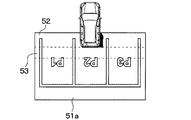
以下、このような構成の車両周囲画像表示システムの作動について説明する。制御装置2に搭載された書き込み可能なメモリ(例えばRAM)には、図2に示すように、リアルA領域51a、リアルB領域51b、履歴C領域52、および履歴B領域53があらかじめ確保されている。
Hereinafter, the operation of the vehicle surrounding image display system having such a configuration will be described. As shown in FIG. 2, a
リアルA領域51aおよびリアルB領域51bは、自車両の周囲のうち自車両の後方の鳥瞰画像を保存するための領域であり、後述するように、最新の撮影画像が鳥瞰変換された鳥瞰画像が保存されるようになっている。
The
また、リアルA領域51aは、車両の後方を車両の前後方向に2分割したうちの、車両からより離れた方の所定の範囲の鳥瞰画像を保存するための領域である。また、リアルB領域51bは、同様に2分割したうちの、車両により近い方の所定の範囲の鳥瞰画像を保存するための領域である。
In addition, the
履歴C領域52は、自車両の周囲のうち自車両の後方以外(すなわち、車載カメラ1の撮影範囲外)の鳥瞰画像を保存するための領域であり、後述するように、過去の撮影画像が鳥瞰変換された鳥瞰画像が保存されるようになっている。
The
履歴B領域53は、車両の周囲のうち上記リアルB領域51bと同じ範囲の鳥瞰画像を保存するための領域である。ただし、後述するように、リアルB領域51bと異なり、最新の撮影画像ではなく、過去の撮影画像が鳥瞰変換された鳥瞰画像が保存されるようになっている。
The
制御装置2は、このようなリアルA領域51a、リアルB領域51b、履歴C領域52、履歴B領域53を用いて、図3にフローチャートで示す処理を実行するようになっている。制御装置2は、この図3の処理を実行することで、上記鳥瞰変換部21、画像合成部22、車両運動計算部23、影判断部24として機能する。
The
この図3の処理について、1つの事例に沿って説明する。なお、この事例においては、車載カメラ1の撮影画像中に自車両の影以外の影は写らないものとする。
The process of FIG. 3 will be described along one example. In this case, it is assumed that no shadow other than the shadow of the host vehicle is captured in the captured image of the in-
まず、制御装置2が図3の処理を開始する際は、リアルA領域51a、リアルB領域51b、履歴C領域52、履歴B領域53のそれぞれの領域内は、鳥瞰画像のデータが全く含まれていない空の状態、換言すれば、空を示すデータのみが含まれている状態となっている。
First, when the
制御装置2は、まずステップ105で、入力された最新のシフトレンジ情報に基づいて、自車両のシフト位置がリバース(後退位置)であるか否か判定し、リバースでなければ再度ステップ105の判定を実行する。
First, at
ドライバーが、駐車場の駐車マス(図4A〜図4FのP2)に自車両を駐車させようとするとき、シフトレンジをR(リバース)に入れたとする。すると制御装置2は、ステップ105で、シフト位置がリバースであると判定し、ステップ110に進む。
It is assumed that the driver puts the shift range into R (reverse) when trying to park the host vehicle in the parking space (P2 in FIGS. 4A to 4F) of the parking lot. Then, the
ステップ110では、車載カメラ1から最新の撮影画像の入力を1枚受け付けて取得する。続いてステップ115では、直前のステップ110で取得した最新の撮影画像に対して周知の鳥瞰変換を施す。この鳥瞰変換によって、撮影画像は、自車両の情報から(真下にまたは斜め下に)見下ろす視点の鳥瞰画像に、変換される。
In
なお、この鳥瞰変換の際には、周知の通り、撮影画像中の物体は高さゼロの位置(すなわち、路面)に存在すると仮定されている。鳥瞰変換に用いられる変換式は、あらかじめ制御装置2のメモリ(例えばROM)に記録されている。制御装置2は、このステップ115の処理を実行することで、鳥瞰変換部21として機能する。
In this bird's-eye view conversion, as is well known, it is assumed that the object in the captured image exists at a position of zero height (that is, the road surface). The conversion formula used for the bird's eye conversion is recorded in advance in a memory (for example, ROM) of the
続いてステップ120では、直前のステップ115において作成した鳥瞰画像を、メモリ中のリアルA領域51aおよびリアルB領域51bに保存する。
Subsequently, in
具体的には、当該鳥瞰画像を車両の前後方向に2分割したうちの、車両からより離れた方の所定の範囲の画像を、リアルA領域51aに保存し、当該鳥瞰画像を同様に2分割したうちの、車両により近い方の所定の範囲の画像を、リアルB領域51bに保存する。
Specifically, an image in a predetermined range farther from the vehicle out of the bird's-eye view image divided in two in the front-rear direction of the vehicle is stored in the
続いてステップ125では、直前のステップ115において作成した鳥瞰画像のうち、リアルB領域51b内に保存された鳥瞰画像中に、影が存在するか否か判定する。
Subsequently, in
当該鳥瞰画像中に影が存在するか否かは、周知の方法(例えば、特許文献2、非特許文献1に記載の方法)で判定すればよい。例えば特許文献2に記載の影検出技術を用いて判定可能である。
Whether or not a shadow is present in the bird's-eye view image may be determined by a known method (for example, the method described in
具体的には、リアルB領域51b内の鳥瞰画像の一部領域に対して、色相と輝度に基づいて領域分割を行い、分割された複数の領域のうち、色相の差が所定の閾値以下でありかつ輝度の差が所定値異常となっている2つの領域を抽出する。
Specifically, the partial area of the bird's-eye view image in the
そして、抽出した2つのうち輝度の高い方を非陰影領域とし、輝度の低い方を陰影領域とする。そして、色情報の空間(特許文献2の図14(b)を参照)における当該陰影領域から非陰影領域へのベクトルを、光源の色情報として特定する。 Then, of the extracted two, the higher luminance is set as a non-shadow region, and the lower luminance is set as a shadow region. Then, a vector from the shadow area to the non-shadow area in the color information space (see FIG. 14B of Patent Document 2) is specified as the color information of the light source.
そして、リアルB領域51b内の鳥瞰画像の全領域について、色相と輝度に基づいて領域分割を行い、隣接する領域間の色相の差が光源の色相と所定の範囲内で一致する場合に、それら隣接する領域のうち、輝度の低い方を、影であると特定する。制御装置2は、このステップ125の処理を実行することで、影判断部24として機能する。
Then, the entire area of the bird's-eye view image in the
本事例では、図3の処理を開始した時点で、図4Aに示すように、自車両の後方(進行方向)の、リアルB領域51bに対応する範囲内に自車両の影が存在するとする。この場合、ステップ125では影があると判定してステップ145に進む。
In this case, when the process of FIG. 3 is started, as shown in FIG. 4A, it is assumed that the shadow of the own vehicle exists within the range corresponding to the
ステップ145では、履歴B領域53中に鳥瞰画像のデータが所定量以上あるか否か判定する。例えば、履歴B領域53のすべてを、鳥瞰画像のデータが満たしたときに、履歴B領域53中に鳥瞰画像のデータが所定量以上あると判定し、それ以外の場合は、履歴B領域53中に鳥瞰画像のデータが所定量未満であると判定してもよい。
In
本事例では、図3の処理が始まったばかりなので、履歴B領域53中に鳥瞰画像のデータが全くないので、所定量未満であると判定してステップ130に進む。
In this example, since the process of FIG. 3 has just started, there is no bird's-eye image data in the
ステップ130では、図2の左側に示すような配置で、リアルA領域51a、リアルB領域51b、および履歴C領域52の画像を繋ぎ合わせて合成し、合成後の合成鳥瞰画像を、制御装置2中の所定の出力用メモリに保存する。
In
なお、合成鳥瞰画像には、図2に示すように、自車両の形状を示す画像54を重畳してもよい。その際、合成鳥瞰画像と車両形状画像54とが重なる部分で合成鳥瞰画像と車両形状画像54の両方が視認可能なように、車両形状画像54を透過的に重畳するようになっていてもよい。
In addition, as shown in FIG. 2, you may superimpose the
制御装置2は、このステップ130の処理を実行することで、画像合成部22として機能する。この出力用メモリに保存された合成鳥瞰画像は、制御装置2から画像表示装置3に入力され、その結果、画像表示装置3は当該合成鳥瞰画像をドライバーに表示する。
The
続いてステップ135では、自車両から入力された各種車両挙動情報、すなわち、シフトレンジの情報、車速の情報、およびステアリング角(またはヨーレート)の最新の情報(過去の情報を追加で用いて)に基づいて、周知のAckermanモデルに従った自車両の動き量(移動ベクトルおよび姿勢変化角度)を算出する。なお、ここでいう動き量とは、前回の撮影画像の取得タイミングから今回の撮影画像の取得タイミングまでの期間における車両の動き(すなわち、撮影画像の取得間隔における動き量)を示す動き量である。制御装置2は、このステップ135の処理を実行することで、車両運動計算部23として機能する。
Subsequently, in
続いてステップ140では、直前のステップ135で算出した自車両の動き量に基づいて、自車両の周囲(路面に固定されていると仮定する)が相対的に自車両に対してどのように移動するかを表す相対移動量を算出する。
Subsequently, in
具体的には、直前のステップ135で算出した自車両の動き量と逆の動きを算出する。例えば、自車両の移動ベクトルが(α、β)で、姿勢変化角度がθであるとき、自車両に対する周囲の相対移動量としては、移動ベクトルが(−α、−β)で、姿勢変化角度が−θであるとする。
Specifically, a movement opposite to the movement amount of the own vehicle calculated in the immediately preceding
そして、リアルA領域51a、リアルB領域51b、および履歴C領域52cを図2の左側のような配置で繋ぎ合わせた結合領域内で、上記のようにして算出された周囲の相対移動量に従って、当該結合領域内の鳥瞰画像が車両の現在の周囲の配置を反映するよう、当該結合領域内に保存されたすべての鳥瞰画像を移動させる。
Then, in the combined area where the
これにより、当該相対移動量に応じて、リアルB領域51bと履歴C領域52の境界で、リアルB領域51bから履歴C領域52に、または、履歴C領域52からリアルB領域51bに、鳥瞰画像の一部が移動する。本事例では、自車両が後退しているので、前者となる。また、リアルB領域51b中にある自車両の影の画像が、履歴C領域52に移動する。
Thereby, according to the relative movement amount, a bird's-eye view image at the boundary between the
それと共にステップ140では、リアルA領域51aおよび履歴B領域53を図2の右側のような配置で繋ぎ合わせた領域内(履歴C領域52は繋ぎ合わせられていないことに注意)で、上記のようにして算出された周囲の相対移動量に従って、鳥瞰画像を移動させる。したがって、車両の後退と共に、図3の処理の開始当初は空だった履歴C領域52内で鳥瞰画像が増加する。
At the same time, in
これにより、当該相対移動量に応じて、リアルA領域51aと履歴B領域53の境界で、リアルA領域51aから履歴B領域53に、または、履歴B領域53からリアルA領域51aに、鳥瞰画像の一部が移動する。本事例では、自車両が後退しているので、前者となる。したがって、車両の後退と共に、図3の処理の開始当初は空だった履歴B領域53内で鳥瞰画像が増加する。
Thereby, according to the relative movement amount, a bird's-eye view image from the
ステップ140の後、処理はステップ105に戻る。その後、車両が後退を続け、自車両の影が最新の撮影画像内(リアルB領域51bに対応する位置内)にあり続けたとする。この場合、履歴B領域53中の鳥瞰画像のデータが所定量に満たない間は、制御装置2は、ステップ105でシフト位置がリバースであると判定し、ステップ125で影があると判定し、ステップ145で履歴B領域53内で鳥瞰画像のデータは所定量未満であると判定する。
After
したがって、制御装置2は、ステップ105、110、115、120、125、145、130、135、140をこの順で繰り返し実行する。各ステップの処理内容は既に説明したものと同様である。
Therefore, the
その結果、図4A、図4B、図4Cに示すように、車両の後退(直進後退でも曲がって後退でもよい)に合わせて、リアルB領域51b内の鳥瞰画像が次第に履歴C領域52内に蓄積されていく。この間、すでに説明した通り、ステップ130において、リアルA領域51a、リアルB領域51b、および履歴C領域52内の鳥瞰画像を繋ぎ合わせた合成鳥瞰画像(および車両の画像54)が、画像表示装置3に表示され続ける。
As a result, as shown in FIG. 4A, FIG. 4B, and FIG. 4C, the bird's-eye view image in the
またこの間、リアルB領域51b中の鳥瞰画像には自車両の影が存在し続けるので、履歴C領域52には影のある鳥瞰画像が直積され続ける。したがって、図4A、図4B、図4Cのように、実際には存在しない影が履歴C領域52内で画像として拡大していく。
During this time, since the shadow of the host vehicle continues to exist in the bird's-eye view image in the
また、上記のように制御装置2がステップ105、110、115、120、125、145、130、135、140をこの順に繰り返し実行することで、車両の後退(直進後退でも曲がって後退でもよい)に合わせて、リアルA領域51a内の鳥瞰画像が次第に履歴B領域53内に蓄積されていく。ただしこの間、履歴B領域53は画像表示装置3における表示には用いられない。
In addition, as described above, the
リアルA領域51aは、リアルB領域51bと比べて、車両の後端からより離れた後方位置(例えば、自車両後端よりも3メートル以上離れた後方)の鳥瞰画像を保存する。したがって、リアルA領域51a中の鳥瞰画像に自車両の影が写っている可能性は比較的低い。本事例では、リアルA領域51a中の鳥瞰画像に自車両の影が写っていないとする。したがって、リアルA領域51aから移動して履歴B領域53に蓄積されていく鳥瞰画像にも、自車両の影が写っていない。
The
その後、自車両の影が最新の撮影画像内(リアルB領域51bに対応する位置内)にあり続ける状態のまま、自車両が後退を続けた結果、履歴B領域53中の鳥瞰画像のデータが所定量以上となったとする。
After that, as a result of the own vehicle continuing to retreat while the shadow of the own vehicle continues to be in the latest photographed image (in the position corresponding to the
この場合、制御装置2は、ステップ105でシフト位置がリバースであると判定し、ステップ125で影があると判定し、ステップ145に進むが、ステップ145では、履歴B領域53内で鳥瞰画像のデータが所定量以上であると判定するので、ステップ150に進む。
In this case, the
ステップ150では、図2の右側に示すような配置で、リアルA領域51a、履歴B領域53、および履歴C領域52の画像を繋ぎ合わせて合成し、合成後の合成鳥瞰画像を、制御装置2中の所定の出力用メモリに保存する。
In
ステップ150の処理がステップ130と違うのは、リアルB領域51b(影がある)に代えて履歴B領域53(影がない)を用いている点である。なお、合成鳥瞰画像には、ステップ130と同様に、自車両の形状を示す画像54を重畳してもよい。
The processing of
このように、リアルB領域51b(影がある)に代えて履歴B領域53(影がない)を用いて表示することで、図4Dに示すように、自車両の後方において、鳥瞰画像中に今まであった影が消滅する。ただし、既に履歴C領域52に移動した影については、引き続き表示される。
In this way, by displaying using the history B area 53 (without shadow) instead of the
制御装置2は、このステップ150の処理を実行することで、画像合成部22として機能する。この出力用メモリに保存された合成鳥瞰画像は、制御装置2から画像表示装置3に入力され、その結果、画像表示装置3は当該合成鳥瞰画像をドライバーに表示する。
The
続いてステップ155では、ステップ130と同じ方法で、周知のAckermanモデルに従った自車両の動き量(移動ベクトルおよび姿勢変化角度)を算出する。制御装置2は、このステップ155の処理を実行することで、車両運動計算部23として機能する。
Subsequently, in
続いてステップ160では、直前のステップ155で算出した自車両の動き量に基づいて、自車両の周囲(路面に固定されていると仮定する)が相対的に自車両に対してどのように移動するかを表す相対移動量を、ステップ140と同様の方法で算出する。
Subsequently, in
そして、リアルA領域51a、履歴B領域53、および履歴C領域52cを図2の右側のような配置で繋ぎ合わせた結合領域内で、上記のようにして算出された周囲の相対移動量に従って、当該結合領域内の鳥瞰画像が車両の現在の周囲の配置を反映するよう、当該結合領域に保存されているすべての鳥瞰画像を移動させる。
Then, in the combined area where the
これにより、当該相対移動量に応じて、リアルA領域51aと履歴B領域53の境界で、リアルA領域51aから履歴B領域53に、または、履歴B領域53からリアルA領域51aに、鳥瞰画像の一部が移動する。本事例では、自車両が後退しているので、前者となる。したがって、車両の後退と共に、図3の処理の開始当初は空だった履歴B領域53内で鳥瞰画像が増加する。
Thereby, according to the relative movement amount, a bird's-eye view image from the
これにより、当該相対移動量に応じて、履歴B領域53と履歴C領域52の境界で、履歴B領域53から履歴C領域52に、または、履歴C領域52から履歴B領域53に、鳥瞰画像の一部が移動する。本事例では、自車両が後退しているので、前者となる。このとき、リアルB領域51b中に自車両の影が無いので、履歴C領域52にも自車両の影の画像が移動することはない。
Thereby, according to the relative movement amount, the bird's-eye view image from the
ステップ160の後、処理はステップ105に戻る。その後、車両が後退を続け、自車両の影が最新の撮影画像内(リアルB領域51bに対応する位置内)にあり続けたとする。この場合、制御装置2は、ステップ105でシフト位置がリバースであると判定し、ステップ125で影があると判定し、ステップ145で履歴B領域53内で鳥瞰画像のデータは所定量以上であると判定する。
After
したがって、制御装置2は、ステップ105、110、115、120、125、145、150、155、160をこの順で繰り返し実行する。各ステップの処理内容は既に説明したものと同様である。
Therefore, the
その結果、図4D、図4E、図4Fに示すように、車両の後退(直進後退でも曲がって後退でもよい)に合わせて、リアルA領域51a内の鳥瞰画像が次第に履歴B領域53内に蓄積されていくと共に、履歴B領域53内の鳥瞰画像が次第に履歴C領域52内に蓄積されていく。
As a result, as shown in FIG. 4D, FIG. 4E, and FIG. 4F, the bird's-eye view image in the
この間、すでに説明した通り、ステップ150において、リアルA領域51a、履歴B領域53、および履歴C領域52内の鳥瞰画像を繋ぎ合わせた合成鳥瞰画像(および車両の画像54)が、画像表示装置3に表示され続ける。
During this time, as already described, in
またこの間、履歴B領域53中の鳥瞰画像には自車両の影が存在しないので、履歴C領域52には影のない鳥瞰画像が直積され続ける。したがって、図4D、図4E、図4Fのように、既に移動してしまった影は履歴C領域52中に残って移動するものの、実際には存在しない影が履歴C領域52内で画像として更に拡大していくのを防ぐことができる。
During this time, since the shadow of the host vehicle does not exist in the bird's-eye view image in the
その後、車両の向きが変化する等の理由で、自車両の影がリアルB領域51b中の鳥瞰画像から消えたとする。この場合、制御装置2は、ステップ125で、直前のステップ115において作成した鳥瞰画像中に影が存在しないと判定し、ステップ130に進む。ただし、ステップ130、135、140の処理内容は、既に説明した通りである。ただし今回は、リアルB領域51b内の鳥瞰画像中に自車両の影が存在しないので、ステップ140では、リアルB領域51bから履歴C領域52に影の画像が移動しない。
Thereafter, it is assumed that the shadow of the host vehicle disappears from the bird's-eye view image in the
その後、自車両の影がリアルB領域51b中の鳥瞰画像に入っていないまま車両が後退している間、制御装置2は、ステップ125で影が無いと判定するので、ステップ105、110、120、125、130、135、140の処理を繰り返す。この場合も、リアルB領域51b内の鳥瞰画像に影がないので、リアルB領域51bから履歴C領域52に影の画像が移動することがない。
After that, while the vehicle is moving backward without the shadow of the own vehicle being included in the bird's-eye view image in the
このように、リアルB領域51b内の鳥瞰画像に影がない場合は、履歴B領域53ではなくリアルB領域51b内の鳥瞰画像を表示に用いることで、最新の撮影画像を用いて表示する範囲が広がる。
Thus, when there is no shadow in the bird's-eye view image in the
なお、上記事例では、図3の処理が始まった時点で既に、自車両の影が撮影画像に入っていた。しかしながら、図3の処理が始まった時点では自車両の影が撮影画像に入っておらず、後に車両の向きが変化する等の理由で、自車両の影が撮影画像内に現れる事例も考えられる。 In the case described above, the shadow of the host vehicle was already in the captured image when the processing of FIG. 3 started. However, there may be a case where the shadow of the own vehicle appears in the photographed image because the shadow of the own vehicle is not included in the photographed image when the processing of FIG. .
このような場合、自車両の影がリアルB領域51b中の鳥瞰画像に入っていないまま車両が後退している間、制御装置2は、ステップ125で影が無いと判定するので、ステップ105、110、120、125、130、135、140の処理を繰り返す。この場合、リアルB領域51b内の鳥瞰画像に影がないので、リアルB領域51bから履歴C領域52に影の画像が移動することがない。また、この場合、ステップ140で、車両の後退移動に伴ってリアルA領域51aから履歴B領域53に鳥瞰画像が次第に蓄積されていく。
In such a case, since the
その後、履歴B領域53に鳥瞰画像のデータが所定量以上蓄積され、さらにその後、車両の向きが変化する等の理由で、自車両の影がリアルB領域51b中の鳥瞰画像内に現れたとする。この場合、制御装置2は、ステップ125で影があると判定し、ステップ145で履歴B領域53内に鳥瞰画像のデータが所定量以上であると判定してステップ150に進み、ステップ150、155、160の処理を、既に説明したのと同様に実行する。
Thereafter, it is assumed that a predetermined amount or more of bird's-eye image data is accumulated in the
ただし、本事例では、履歴C領域52に全く影の画像が移動していないので、リアルA領域51a、履歴B領域53、履歴C領域52内の鳥瞰画像を繋げた合成画像には影がまったくない。
However, in this example, since no shadow image has moved to the
そしてその後も、撮影画像中(具体的にはリアルB領域51bに該当する範囲の撮影画像中)に影があったとしても、制御装置2は、その後、ステップ105、110、115、120、125、145、150、155、160をこの順で繰り返し実行することで、リアルB領域51b内の最新の撮影画像を用いず、履歴B領域53内の撮影画像を用いるので、リアルA領域51a、履歴B領域53、履歴C領域52内の鳥瞰画像を繋げた合成画像には影がまったくない。
Even after that, even if there is a shadow in the captured image (specifically, in the captured image in the range corresponding to the
なお、本実施形態では、ステップ125では、直前のステップ115で作成したリアルB領域51b内の鳥瞰画像に影が存在するか否かを判定している。しかし、その影が自車両の影であるか他の物体の影であるかについては判定していない。
In this embodiment, in
したがって、一時例として、自車両の影は鳥瞰画像中に無いにもかかわらず、他の物体の影が最新のリアルB領域51b内の鳥瞰画像内にある場合でも、制御装置2は、自車両の影が最新のリアルB領域51b内の鳥瞰画像にある場合と同じ作動を行う。
Therefore, as a temporary example, even when the shadow of the own vehicle is not in the bird's-eye view image, the
すなわち、ステップ125で影があると判定し、履歴B領域53に所定量以上の鳥瞰画像のデータが蓄積されていれば、リアルB領域51bに代えて履歴B領域53を用いることで、図2の右側の配置で組み合わせた合成鳥瞰画像の表示を行い、車両の移動に合わせて、この合成鳥瞰画像をリアルA領域51a、履歴B領域53、履歴C領域52内で移動させる。
That is, if it is determined in
このようになっていても、表示する鳥瞰画像の一部がリアルB領域51b内の最新の鳥瞰画像から履歴B領域53内の少し古い鳥瞰画像に置き換わるだけなので、大きな問題は発生しない。また、仮に影でないものを影であると誤って判定してしまった場合でも、同様に、大きな問題は発生しない。
Even in this case, since a part of the bird's-eye view image to be displayed is simply replaced with the newest bird's-eye view image in the
以上説明した通り、本実施形態では、ステップ150〜160を実行することで、自車両の影が車載カメラ1で撮影されてしまったときにも、画像表示装置3で表示する合成鳥瞰画像の品質の低下を抑えることができる。
As described above, in the present embodiment, the quality of the synthesized bird's-eye image displayed on the image display device 3 even when the shadow of the host vehicle is photographed by the in-
具体的には、履歴B領域53を設け、この履歴B領域53内の鳥瞰画像が車両の現在の周囲の配置を反映するよう、リアルA領域51a内に保存された鳥瞰画像を用いて履歴B領域53内に鳥瞰画像を構成する。
Specifically, a
そして、リアルB領域51bの一部または全部を含む所定の領域に保存された鳥瞰画像内に影があるかないか判定し、履歴C領域52内の鳥瞰画像が車両の現在の周囲の配置を反映するよう、影がない場合は、リアルB領域51b内に保存された鳥瞰画像を用いて履歴C領域52内に鳥瞰画像を構成し、影がある場合は、履歴B領域53内に保存された鳥瞰画像を用いて履歴C領域52内に鳥瞰画像を構成する。
Then, it is determined whether or not there is a shadow in the bird's-eye view image stored in a predetermined region including part or all of the
このように、履歴合成(ここでは、履歴C領域52内の鳥瞰画像を構成することをいう)の元画像としてリアルB領域51bの鳥瞰画像を用いるか履歴B領域53の鳥瞰画像を用いるかを、影の有無に応じて選択できるようにする。
In this way, whether to use the bird's-eye image of the
これにより、影のある場合は、リアルA領域51aの鳥瞰画像(影のない可能性が高い画像)に基づいて構成された履歴B領域53の鳥瞰画像を用いて履歴合成を行うので、履歴C領域52内にて自車両の影が拡大してしまう可能性を低減することができる。
As a result, when there is a shadow, history synthesis is performed using the bird's-eye image of the
また、影のない場合は、リアルB領域51bの鳥瞰画像を用いて履歴合成を行うので、履歴C領域52内の鳥瞰画像の撮影時期が比較的新しくなる。
When there is no shadow, history synthesis is performed using the bird's-eye image of the
なお、本実施形態において、ステップ125で影があると判定した場合でも、ステップ145で履歴B領域53中に所定量以上データがないと判定した場合は、ステップ150〜160で履歴B領域53を表示および履歴C領域52への鳥瞰画像移動に使用するのではなく、ステップ130〜140でリアルB領域51bを表示および履歴C領域52への鳥瞰画像移動に使用する。
In this embodiment, even if it is determined in
このようにするのは、リアルB領域51bの鳥瞰画像中に影があるからといっても、履歴B領域53に充分な量の鳥瞰画像が蓄積されていない段階で履歴B領域53を表示に使用してしまえば、画像表示装置3で表示する合成鳥瞰画像中に空白ができてしまい、更に、その空白が履歴C領域52に移動してしまうからである。
This is because the
なお、上記実施形態において、制御装置2が、ステップ110を実行することで取得手段の一例として機能し、ステップ115を実行することで鳥瞰変換手段の一例として機能し、ステップ120を実行することで分割保存手段の一例として機能し、ステップ125を実行することで影判定手段の一例として機能し、ステップ135、155を実行することで動き算出手段の一例として機能し、ステップ130、150を実行することで表示制御手段の一例として機能し、ステップ130を実行することで第1表示制御手段の一例として機能し、ステップ140を実行することで第1履歴画像構成手段の一例として機能し、ステップ150を実行することで第2表示制御手段の一例として機能し、ステップ160を実行することで第2履歴画像構成手段の一例として機能し、ステップ145を実行することでデータ量判定手段の一例として機能する。
In the above embodiment, the
(他の実施形態)
以上、本発明の実施形態について説明したが、本発明の範囲は、上記実施形態のみに限定されるものではなく、本発明の各発明特定事項の機能を実現し得る種々の形態を包含するものである。例えば、以下のような形態も許容される。
(Other embodiments)
As mentioned above, although embodiment of this invention was described, the scope of the present invention is not limited only to the said embodiment, The various form which can implement | achieve the function of each invention specific matter of this invention is included. It is. For example, the following forms are also acceptable.
(1)ステップ145では、車両が所定距離以上後退移動したか否か(または所定時間以上後退移動したか否か)という判定に置き換えてもよい。これは、車両が十分な距離後退すれば、履歴B領域53に充分な量だけ鳥瞰変換のデータが含まれるはずだという考えに基づいた作動である。
(1) In
(2)上記実施形態のステップ125では、自車両の影から否かは判断せず、リアルB領域51b中に影があれば、それが自車両以外の物体のする影であっても、リアルB領域51b内にあれば影があると判定する。
(2) In
しかし、必ずしもこのようになっておらずともよく、リアルB領域51b内に影があり、その影が自車両の影である場合に限り、影があると判定し、それ以外の場合には影がないと判定するようになっていてもよい。
However, this need not necessarily be the case, and it is determined that there is a shadow only in the
(3)また、上記実施形態では、影があるか否かを判定する範囲として、リアルB領域51b全部の内部の鳥瞰画像のみを対象としていたが、リアルA領域51aの全部およびリアルB領域51bの総和の領域内の鳥瞰画像のみを対象としてもよい。あるいは、リアルA領域51aの一部およびリアルB領域51bの一部の総和の領域内の鳥瞰画像のみを対象としてもよい。あるいは、車載カメラ1の撮影画像全体を対象としてもよい。
(3) In the embodiment described above, only the bird's-eye view image inside the
つまり、リアルB領域51bの一部を含む所定の領域に保存された鳥瞰画像において、影があるか否かを判定すればよい。なぜなら、そのようにしていれば、少なくともリアルB領域51bの当該一部に影がある場合は、ステップ150〜160を実行することで影が表示される量を低減できるからである。また仮に、判定対象のうち、リアルB領域51bに影がなく、他の部分に影があった場合もステップ150〜160を実行する場合があるが、その場合でも、表示される画像が最新でなくなるだけなので、大きな問題はない。
That is, it is only necessary to determine whether or not there is a shadow in the bird's-eye view image stored in a predetermined area including a part of the
(4)上記各実施形態では、車載カメラ1は、車両の後方の所定範囲を繰り返し撮影するようになっていたが、車載カメラ1は、車両の前方の所定範囲を繰り返し撮影するようになっていてもよい。その場合、上記明細書では、車両の前後を入れ替えるように読み替える。
(4) In each of the above embodiments, the in-
(5)また、上記実施形態では、ステップ140において、車両の動き量に基づいて、リアルA領域51a、リアルB領域51b、および履歴C領域52cを繋ぎ合わせた結合領域内で鳥瞰画像を移動させ、それと共に、履歴B領域53およびリアルA領域51aを繋ぎ合わせた結合領域内で鳥瞰画像を移動させるようになっている。
(5) Further, in the above embodiment, in
このようにすると、履歴C領域52内の各位置の鳥瞰画像は、その位置が車載カメラ1の撮影範囲から外れる直前(リアルB領域51bから外れる直前)の鳥瞰画像となっている。しかしながら、必ずしもこのようになっておらずともよい。
In this way, the bird's-eye view image at each position in the
例えば、履歴C領域52内の各位置の鳥瞰画像は、その位置が車載カメラ1の撮影範囲から外れる直前よりも更に前の鳥瞰画像となっていてもよい。
For example, the bird's-eye view image at each position in the
つまり、ステップ140では、履歴C領域52は、履歴C領域52内の鳥瞰画像が車両の現在の周囲の配置を反映するよう、車両の動き量に基づいて、リアルB領域51b内に保存された鳥瞰画像を用いて構成されていれば充分である。
That is, in
(6)また、上記実施形態では、ステップ160において、車両の動き量に基づいて、リアルA領域51a、履歴B領域53、および履歴C領域52cを繋ぎ合わせた結合領域内で鳥瞰画像を移動させるようになっている。
(6) Also, in the above embodiment, in
このようにすると、履歴C領域52内の各位置の鳥瞰画像は、その位置が履歴B領域53から外れる直前の鳥瞰画像となっている。しかしながら、必ずしもこのようになっておらずともよい。
In this way, the bird's-eye view image at each position in the
例えば、履歴C領域52内の各位置の鳥瞰画像は、その位置が履歴B領域53から外れる直前よりも更に前の鳥瞰画像となっていてもよい。
For example, the bird's-eye view image at each position in the
つまり、ステップ160では、履歴C領域52は、履歴C領域52内の鳥瞰画像が車両の現在の周囲の配置を反映するよう、車両の前記動き量に基づいて、履歴B領域53内に保存された鳥瞰画像を用いて構成されていれば充分である。
That is, in
(7)また、上記実施形態では、ステップ140において、車両の動き量に基づいて、リアルA領域51aおよび履歴B領域53を繋ぎ合わせた結合領域内で鳥瞰画像を移動させるようになっている。
(7) Further, in the above embodiment, in
またステップ160において、車両の動き量に基づいて、リアルA領域51a、履歴B領域53、および履歴C領域52cを繋ぎ合わせた結合領域内で鳥瞰画像を移動させるようになっている。
In
これらのようにすると、履歴B領域53内の各位置の鳥瞰画像は、その位置がリアルA領域51aから外れる直前の鳥瞰画像となっている。しかしながら、必ずしもこのようになっておらずともよい。例えば、履歴B領域53内の各位置の鳥瞰画像は、その位置がリアルA領域51aから外れる直前よりも更に前の鳥瞰画像となっていてもよい。
In this way, the bird's-eye view image at each position in the
つまり、履歴B領域53内の鳥瞰画像は、履歴B領域53内の鳥瞰画像が車両の現在の周囲の配置を反映するよう、車両の動き量に基づいて、リアルA領域51a内に保存された鳥瞰画像を用いて構成されていれば充分である。
That is, the bird's-eye view image in the
(8)また、上記実施形態では、履歴B領域53を設けることで、下記(a)、(b)2つの効果を得ることができる。(a)履歴B領域53を用いて表示するので、自車両の移動時に自車両の後方に影がつきまとう可能性が低減される。(b)履歴C領域52には履歴B領域53から画像を移動させるので、自車両の影が履歴C領域52において拡大してしまう可能性が低減される。
(8) Moreover, in the said embodiment, the following (a) and (b) two effects can be acquired by providing the log | history B area |
しかしながら、(a)の効果は必須ではない。すなわち、図3の処理において、ステップ150では、ステップ130と同様、リアルA領域51a、リアルB領域51b、および履歴C領域52内の鳥瞰画像の合成画像を出力用メモリに保存するようになっていてもよい。
However, the effect of (a) is not essential. That is, in the processing of FIG. 3, in
1 車載カメラ
2 制御装置(車両周囲画像表示制御装置)
3 画像表示装置
51a リアルA領域
51b リアルB領域
52 履歴C領域
53 履歴B領域
1 In-
3
Claims (6)
前記取得手段(110)が繰り返し取得した撮影画像に鳥瞰変換を逐次施して鳥瞰画像を作成する鳥瞰変換手段(115)と、
作成された最新の前記鳥瞰画像をメモリに保存する際、前記鳥瞰画像を前記車両の前後方向に分割したうちの、前記車両からより離れた方の所定の範囲の画像を、リアルA領域(51a)に保存し、前記車両により近い方の所定の範囲の画像を、リアルB領域(51b)に保存する分割保存手段(120)と、
前記リアルB領域(51b)の一部または全部を含む所定の領域に保存された鳥瞰画像内に影があるか否かを判定する影判定手段(125)と、
前記車両から入力された車両挙動情報に基づいて、前記車両の動き量を算出する動き算出手段(135、155)と、
前記影判定手段(125)によって影がないと判定された場合、前記車載カメラ(1)の撮影範囲外の鳥瞰画像を保存するための履歴C領域(52)内の鳥瞰画像が前記車両の現在の周囲の配置を反映するよう、前記車両の前記動き量に基づいて、前記リアルB領域(51b)内に保存された鳥瞰画像を用いて前記履歴C領域(52)内に鳥瞰画像を構成すると共に、前記リアルB領域(51b)と同じ範囲の鳥瞰画像を保存するための履歴B領域(53)内の鳥瞰画像が前記車両の現在の周囲の配置を反映するよう、前記車両の前記動き量に基づいて、前記リアルA領域(51a)内に保存された鳥瞰画像を用いて前記履歴B領域(53)内に鳥瞰画像を構成する第1履歴画像構成手段(140)と、
前記影判定手段(125)によって影があると判定された場合、前記車載カメラ(1)の撮影範囲外の鳥瞰画像を保存するための履歴C領域(52)内の鳥瞰画像が前記車両の現在の周囲の配置を反映するよう、前記車両の前記動き量に基づいて、前記履歴B領域(53)内に保存された鳥瞰画像を用いて前記履歴C領域(52)内に鳥瞰画像を構成すると共に、前記履歴B領域(53)内の鳥瞰画像が前記車両の現在の周囲の配置を反映するよう、前記車両の前記動き量に基づいて、前記リアルA領域(51a)内に保存された鳥瞰画像を用いて前記履歴B領域(53)内に鳥瞰画像を構成する第2履歴画像構成手段(160)と、
前記リアルA領域(51a)内の鳥瞰画像、前記履歴C領域(52)内の鳥瞰画像、および、前記リアルB領域(51b)内または前記履歴B領域(53)内の鳥瞰画像を、画像表示装置(3)に表示させる表示制御手段(130、150)と、を備えた車両周囲画像表示制御装置。 Acquisition means (110) for repeatedly acquiring captured images around the vehicle from an in-vehicle camera (1) mounted on the vehicle;
Bird's-eye conversion means (115) for sequentially performing bird's-eye conversion on the captured images repeatedly acquired by the acquisition means (110) to create a bird's-eye view image;
When storing the created latest bird's-eye view image in a memory, an image in a predetermined range farther from the vehicle out of the bird's-eye view image divided in the front-rear direction of the vehicle is displayed in the real A area (51a ) And a storage unit (120) for storing an image in a predetermined range closer to the vehicle in the real B area (51b);
A shadow determination means (125) for determining whether or not there is a shadow in the bird's-eye view image stored in a predetermined area including a part or all of the real B area (51b);
Movement calculating means (135, 155) for calculating the amount of movement of the vehicle based on vehicle behavior information input from the vehicle;
When it is determined by the shadow determining means (125) that there is no shadow, the bird's-eye view image in the history C area (52) for storing the bird's-eye image outside the shooting range of the in-vehicle camera (1) is the current vehicle state. Based on the amount of movement of the vehicle, a bird's-eye view image is configured in the history C region (52) using the bird's-eye image stored in the real B region (51b) so as to reflect the arrangement around the vehicle. In addition, the amount of movement of the vehicle so that the bird's-eye view image in the history B region (53) for storing the bird's-eye image in the same range as the real B region (51b) reflects the current surrounding arrangement of the vehicle. First history image constructing means (140) for constructing a bird's-eye image in the history B region (53) using the bird's-eye image stored in the real A region (51a),
When it is determined by the shadow determining means (125) that there is a shadow, the bird's-eye view image in the history C area (52) for storing the bird's-eye image outside the shooting range of the in-vehicle camera (1) is the current vehicle state. Based on the amount of movement of the vehicle, a bird's-eye view image is configured in the history C region (52) using a bird's-eye image stored in the history B region (53) based on the amount of movement of the vehicle. At the same time, the bird's-eye view stored in the real A region (51a) based on the amount of movement of the vehicle so that the bird's-eye view image in the history B region (53) reflects the current surrounding arrangement of the vehicle. Second history image constructing means (160) for constructing a bird's-eye view image in the history B area (53) using an image;
Image display of the bird's-eye view image in the real A area (51a), the bird's-eye view image in the history C area (52), and the bird's-eye view image in the real B area (51b) or the history B area (53) A vehicle surrounding image display control device comprising display control means (130, 150) for display on the device (3).
前記影判定手段(125)によって影がないと判定されたことに基づいて、前記リアルA領域(51a)内の鳥瞰画像、前記リアルB領域(51b)内の鳥瞰画像、および前記履歴C領域(52)内の鳥瞰画像を、前記画像表示装置(3)に表示させる第1表示制御手段(130)と、
前記影判定手段(125)によって影があると判定されたことに基づいて、前記リアルA領域(51a)内の鳥瞰画像、前記履歴B領域(53)内の鳥瞰画像、および前記履歴C領域(52)内の鳥瞰画像を、前記画像表示装置(3)に表示させる第2表示制御手段(150)と、を有することを特徴とする請求項1に記載の車両周囲画像表示制御装置。 The display control means includes
Based on the fact that the shadow determining means (125) determines that there is no shadow, the bird's-eye image in the real A area (51a), the bird's-eye image in the real B area (51b), and the history C area ( 52) first display control means (130) for causing the image display device (3) to display the bird's-eye view image in the image display device (3);
Based on the determination by the shadow determining means (125) that there is a shadow, the bird's-eye image in the real A area (51a), the bird's-eye image in the history B area (53), and the history C area ( 52) The vehicle surrounding image display control device according to claim 1, further comprising second display control means (150) for displaying the bird's-eye view image in the image display device (3).
前記第1履歴画像構成手段(140)は、前記影判定手段(125)によって影がないと判定された場合、および、前記影判定手段(125)によって影があると判定され且つ前記データ量判定手段(145)によって所定量以上ないと判定された場合のそれぞれにおいて、前記履歴C領域(52)内の鳥瞰画像が前記車両の現在の周囲の配置を反映するよう、前記車両の前記動き量に基づいて、前記リアルB領域(51b)内に保存された鳥瞰画像を用いて前記履歴C領域(52)内に鳥瞰画像を構成すると共に、前記履歴B領域(53)内の鳥瞰画像が前記車両の現在の周囲の配置を反映するよう、前記車両の前記動き量に基づいて、前記リアルA領域(51a)内に保存された鳥瞰画像を用いて前記履歴B領域(53)内に鳥瞰画像を構成し、
前記第2履歴画像構成手段(160)は、前記影判定手段(125)によって影があると判定され且つ前記データ量判定手段(145)によって所定量以上あると判定された場合、前記履歴C領域(52)内の鳥瞰画像が前記車両の現在の周囲の配置を反映するよう、前記車両の前記動き量に基づいて、前記履歴B領域(53)内に保存された鳥瞰画像を用いて前記履歴C領域(52)内に鳥瞰画像を構成すると共に、前記履歴B領域(53)内の鳥瞰画像が前記車両の現在の周囲の配置を反映するよう、前記車両の前記動き量に基づいて、前記リアルA領域(51a)内に保存された鳥瞰画像を用いて前記履歴B領域(53)内に鳥瞰画像を構成することを特徴とする請求項1または2に記載の車両周囲画像表示制御装置。 A data amount judging means (145) for judging whether or not there is a predetermined amount or more of bird's-eye image data in the history B region (53);
The first history image construction unit (140) determines that there is no shadow by the shadow determination unit (125), and determines that there is a shadow by the shadow determination unit (125) and determines the data amount. In each of the cases where the means (145) determines that the predetermined amount is not exceeded, the movement amount of the vehicle is adjusted so that the bird's-eye view image in the history C region (52) reflects the current surrounding arrangement of the vehicle. Based on the above, the bird's-eye view image stored in the real B region (51b) is used to form a bird's-eye view image in the history C region (52), and the bird's-eye view image in the history B region (53) is the vehicle. Based on the amount of movement of the vehicle, the bird's-eye view image is stored in the history B region (53) using the bird's-eye image stored in the real A region (51a) based on the amount of movement of the vehicle. None,
When the second history image constituting unit (160) determines that there is a shadow by the shadow determining unit (125) and the data amount determining unit (145) determines that there is a predetermined amount or more, the history C region The history using the bird's-eye image stored in the history B area (53) based on the amount of movement of the vehicle so that the bird's-eye image in (52) reflects the current surrounding arrangement of the vehicle. Based on the amount of movement of the vehicle, the bird's-eye view image in the history B region (53) reflects the current surrounding arrangement of the vehicle while configuring the bird's-eye view image in the region C (52). 3. The vehicle surrounding image display control device according to claim 1, wherein a bird's-eye view image is configured in the history B region (53) using a bird's-eye view image stored in the real A region (51 a).
第1履歴画像構成手段(160)は、前記影判定手段(125)によって影があると判定されたことに基づいて、前記車両の前記動き量に基づいて、前記リアルA領域(51a)、前記履歴B領域(53)、および前記履歴C領域(52c)を繋ぎ合わせた結合領域内で鳥瞰画像を移動させる第2移動手段(160)と、を備えた請求項1ないし3のいずれか1つに車両周囲画像表示制御装置。 Based on the fact that the shadow determination means (125) determines that there is no shadow, the first history image composing means (140) is configured to determine the real A area (51a), the A bird's-eye view image is moved within a combined region obtained by joining the real B region (51b) and the history C region (52c), and at the same time, a bird's-eye image in the same range as the real B region (51b) is stored. The bird's-eye view image is moved within a combined area obtained by connecting the history B area (53) and the real A area (51a),
The first history image composing means (160), based on the fact that the shadow determining means (125) determines that there is a shadow, based on the amount of movement of the vehicle, the real A area (51a), the A history B area (53) and a second moving means (160) for moving a bird's-eye view image within a combined area obtained by joining the history C areas (52c). Vehicle surrounding image display control device.
前記取得手段(110)が繰り返し取得した撮影画像に鳥瞰変換を逐次施して鳥瞰画像を作成する鳥瞰変換手段(115)と、
作成された最新の前記鳥瞰画像をメモリに保存する際、前記鳥瞰画像を前記車両の前後方向に分割したうちの、前記車両からより離れた方の所定の範囲の画像を、リアルA領域(51a)に保存し、前記車両により近い方の所定の範囲の画像を、リアルB領域(51b)に保存する分割保存手段(120)と、
前記リアルB領域(51b)の一部または全部を含む所定の領域に保存された鳥瞰画像内に影があるか否かを判定する影判定手段(125)と、
前記車両から入力された車両挙動情報に基づいて、前記車両の動き量を算出する動き算出手段(135、155)と、
前記影判定手段(125)によって影がないと判定された場合、前記車載カメラ(1)の撮影範囲外の鳥瞰画像を保存するための履歴C領域(52)内の鳥瞰画像が前記車両の現在の周囲の配置を反映するよう、前記車両の前記動き量に基づいて、前記リアルB領域(51b)内に保存された鳥瞰画像を用いて前記履歴C領域(52)内に鳥瞰画像を構成すると共に、前記リアルB領域(51b)と同じ範囲の鳥瞰画像を保存するための履歴B領域(53)内の鳥瞰画像が前記車両の現在の周囲の配置を反映するよう、前記車両の前記動き量に基づいて、前記リアルA領域(51a)内に保存された鳥瞰画像を用いて前記履歴B領域(53)内に鳥瞰画像を構成する第1履歴画像構成手段(140)と、
前記影判定手段(125)によって影があると判定された場合、前記車載カメラ(1)の撮影範囲外の鳥瞰画像を保存するための履歴C領域(52)内の鳥瞰画像が前記車両の現在の周囲の配置を反映するよう、前記車両の前記動き量に基づいて、前記履歴B領域(53)内に保存された鳥瞰画像を用いて前記履歴C領域(52)内に鳥瞰画像を構成すると共に、前記履歴B領域(53)内の鳥瞰画像が前記車両の現在の周囲の配置を反映するよう、前記車両の前記動き量に基づいて、前記リアルA領域(51a)内に保存された鳥瞰画像を用いて前記履歴B領域(53)内に鳥瞰画像を構成する第2履歴画像構成手段(160)と、
前記リアルA領域(51a)内の鳥瞰画像、前記履歴C領域(52)内の鳥瞰画像、および、前記リアルB領域(51b)内または前記履歴B領域(53)内の鳥瞰画像を、画像表示装置(3)に表示させる表示制御手段(130、150)と、として、前記車両に搭載される制御装置(2)を機能させるプログラム。 Acquisition means (110) for repeatedly acquiring captured images around the vehicle from an in-vehicle camera (1) mounted on the vehicle;
Bird's-eye conversion means (115) for sequentially performing bird's-eye conversion on the captured images repeatedly acquired by the acquisition means (110) to create a bird's-eye view image;
When storing the created latest bird's-eye view image in a memory, an image in a predetermined range farther from the vehicle out of the bird's-eye view image divided in the front-rear direction of the vehicle is displayed in the real A area (51a ) And a storage unit (120) for storing an image in a predetermined range closer to the vehicle in the real B area (51b);
A shadow determination means (125) for determining whether or not there is a shadow in the bird's-eye view image stored in a predetermined area including a part or all of the real B area (51b);
Movement calculating means (135, 155) for calculating the amount of movement of the vehicle based on vehicle behavior information input from the vehicle;
When it is determined by the shadow determining means (125) that there is no shadow, the bird's-eye view image in the history C area (52) for storing the bird's-eye image outside the shooting range of the in-vehicle camera (1) is the current vehicle state. Based on the amount of movement of the vehicle, a bird's-eye view image is configured in the history C region (52) using the bird's-eye image stored in the real B region (51b) so as to reflect the arrangement around the vehicle. In addition, the amount of movement of the vehicle so that the bird's-eye view image in the history B region (53) for storing the bird's-eye image in the same range as the real B region (51b) reflects the current surrounding arrangement of the vehicle. First history image constructing means (140) for constructing a bird's-eye image in the history B region (53) using the bird's-eye image stored in the real A region (51a),
When it is determined by the shadow determining means (125) that there is a shadow, the bird's-eye view image in the history C area (52) for storing the bird's-eye image outside the shooting range of the in-vehicle camera (1) is the current vehicle state. Based on the amount of movement of the vehicle, a bird's-eye view image is configured in the history C region (52) using a bird's-eye image stored in the history B region (53) based on the amount of movement of the vehicle. At the same time, the bird's-eye view stored in the real A region (51a) based on the amount of movement of the vehicle so that the bird's-eye view image in the history B region (53) reflects the current surrounding arrangement of the vehicle. Second history image constructing means (160) for constructing a bird's-eye view image in the history B area (53) using an image;
Image display of the bird's-eye view image in the real A area (51a), the bird's-eye view image in the history C area (52), and the bird's-eye view image in the real B area (51b) or the history B area (53) A program that causes the control device (2) mounted on the vehicle to function as display control means (130, 150) to be displayed on the device (3).
撮影画像に鳥瞰変換を逐次施して、鳥瞰画像を作成する鳥瞰変換装置(115)と、A bird's-eye conversion device (115) for sequentially performing bird's-eye conversion on a captured image to create a bird's-eye image;
前記車両から入力された車両挙動情報に基づいて、前記車両の動き量を算出する動き算出装置(135、155)と、A motion calculation device (135, 155) for calculating the amount of motion of the vehicle based on vehicle behavior information input from the vehicle;
前記車両の周囲の所定のB範囲のB鳥瞰画像を記憶するリアルB領域と、前記B範囲よりも前記車両からより離れた所定のA範囲のA鳥瞰画像を記憶するリアルA領域と、前記リアルA領域が記憶していた前記A鳥瞰画像を前記動き算出装置が算出した前記車両の動き量に基づいて前記車両との相対位置を移動させて履歴B鳥瞰画像として記憶する履歴B領域と、前記履歴B領域が記憶していた前記履歴B鳥瞰画像または前記リアルB領域が記憶していた前記B鳥瞰画像を、前記動き算出装置が算出した前記車両の動き量に基づいて前記車両との相対位置を移動させてC鳥瞰画像として記憶する履歴C領域と、を有するメモリと、A real B area for storing a B bird's-eye image of a predetermined B range around the vehicle; a real A area for storing an A bird's-eye image of a predetermined A range farther from the vehicle than the B range; A history B area for storing the A bird's-eye image stored in the A area as a history B bird's-eye image by moving a relative position of the vehicle based on the amount of movement of the vehicle calculated by the motion calculation device; Relative position of the history B bird's-eye image stored in the history B region or the B bird's-eye image stored in the real B region based on the amount of movement of the vehicle calculated by the motion calculation device A memory having a history C region that is moved and stored as a C bird's-eye image,
前記鳥瞰画像を前記車両の前後方向に分割することで、前記A鳥瞰画像と前記B鳥瞰画像を作成し、前記A鳥瞰画像を前記リアルA領域(51a)に保存し、前記B鳥瞰画像を前記リアルB領域(51b)に保存する分割保存装置(120)と、The A bird's-eye view image and the B bird's-eye view image are created by dividing the bird's-eye view image in the longitudinal direction of the vehicle, the A bird's-eye view image is stored in the real A area (51a), and the B bird's-eye view image is A split storage device (120) for storing in the real B area (51b);
前記リアルB領域(51b)の一部または全部に保存されたB鳥瞰画像に影があるか否かを判定する影判定装置(125)と、A shadow determination device (125) for determining whether or not the B bird's-eye view image stored in a part or all of the real B region (51b) has a shadow;
前記影判定装置(125)が、B鳥瞰画像に影がないと判定した場合、前記リアルB領域(51b)に保存されていたB鳥瞰画像を用いて前記履歴C領域(52)内に前記C鳥瞰画像を構成する第1履歴画像構成装置(140)と、When the shadow determination device (125) determines that there is no shadow in the B bird's-eye view image, the C bird's-eye image stored in the real B region (51b) is used to store the C in the history C region (52). A first history image constructing device (140) for constructing a bird's-eye view image;
前記影判定装置(125)が、B鳥瞰画像に影があると判定した場合、前記履歴B領域(53)内に保存されていた履歴B鳥瞰画像を用いて前記履歴C領域(52)内に前記C鳥瞰画像を構成する第2履歴画像構成装置(160)と、When the shadow determination device (125) determines that there is a shadow in the B bird's-eye view image, the history C region (52) uses the history B bird's-eye image stored in the history B region (53). A second history image construction device (160) constituting the C bird's-eye view image;
前記リアルA領域(51a)内の前記A鳥瞰画像、前記履歴C領域(52)内の前記C鳥瞰画像、および、前記リアルB領域(51b)内の前記B鳥瞰画像または前記履歴B領域(53)内の前記履歴B鳥瞰画像を、画像表示装置(3)に表示させる表示制御装置(130、150)と、を備えた車両周囲画像表示制御装置。The A bird's-eye view image in the real A area (51a), the C bird's-eye view image in the history C area (52), and the B bird's-eye view image or the history B area (53 in the real B area (51b)) And a display control device (130, 150) that causes the image display device (3) to display the history B bird's-eye view image.
Priority Applications (5)
| Application Number | Priority Date | Filing Date | Title |
|---|---|---|---|
| JP2012117762A JP6003226B2 (en) | 2012-05-23 | 2012-05-23 | Vehicle surrounding image display control apparatus and vehicle surrounding image display control program |
| EP13793824.7A EP2854098B1 (en) | 2012-05-23 | 2013-03-08 | Vehicle surroundings image display control device, vehicle surroundings image display control method, non-transitory tangible computer-read medium comprising command containing said method, and image processing method effecting top-view conversion and display of image of vehicle surroundings |
| PCT/JP2013/001489 WO2013175684A1 (en) | 2012-05-23 | 2013-03-08 | Vehicle surroundings image display control device, vehicle surroundings image display control method, non-transitory tangible computer-read medium comprising command containing said method, and image processing method effecting top-view conversion and display of image of vehicle surroundings |
| CN201380026870.XA CN104335241B (en) | 2012-05-23 | 2013-03-08 | Vehicle surroundings image display control device, display method and image processing method |
| US14/395,514 US20150070394A1 (en) | 2012-05-23 | 2013-03-08 | Vehicle surrounding image display control device, vehicle surrounding image display control method, non-transitory tangible computer-readable medium comprising command including the method, and image processing method executing top view conversion and display of image of vehicle surroundings |
Applications Claiming Priority (1)
| Application Number | Priority Date | Filing Date | Title |
|---|---|---|---|
| JP2012117762A JP6003226B2 (en) | 2012-05-23 | 2012-05-23 | Vehicle surrounding image display control apparatus and vehicle surrounding image display control program |
Publications (3)
| Publication Number | Publication Date |
|---|---|
| JP2013246493A JP2013246493A (en) | 2013-12-09 |
| JP2013246493A5 JP2013246493A5 (en) | 2014-09-18 |
| JP6003226B2 true JP6003226B2 (en) | 2016-10-05 |
Family
ID=49623400
Family Applications (1)
| Application Number | Title | Priority Date | Filing Date |
|---|---|---|---|
| JP2012117762A Active JP6003226B2 (en) | 2012-05-23 | 2012-05-23 | Vehicle surrounding image display control apparatus and vehicle surrounding image display control program |
Country Status (5)
| Country | Link |
|---|---|
| US (1) | US20150070394A1 (en) |
| EP (1) | EP2854098B1 (en) |
| JP (1) | JP6003226B2 (en) |
| CN (1) | CN104335241B (en) |
| WO (1) | WO2013175684A1 (en) |
Cited By (1)
| Publication number | Priority date | Publication date | Assignee | Title |
|---|---|---|---|---|
| KR20190114283A (en) * | 2018-03-29 | 2019-10-10 | 주식회사평화발레오 | Clutch assembly having fulcrum ring centering function |
Families Citing this family (21)
| Publication number | Priority date | Publication date | Assignee | Title |
|---|---|---|---|---|
| JP5994437B2 (en) * | 2012-07-04 | 2016-09-21 | 株式会社デンソー | Vehicle surrounding image display control apparatus and vehicle surrounding image display control program |
| JP6327115B2 (en) * | 2014-11-04 | 2018-05-23 | 株式会社デンソー | Vehicle periphery image display device and vehicle periphery image display method |
| KR102426631B1 (en) * | 2015-03-16 | 2022-07-28 | 현대두산인프라코어 주식회사 | Method of displaying a dead zone of a construction machine and apparatus for performing the same |
| JP6464846B2 (en) | 2015-03-17 | 2019-02-06 | 株式会社デンソー | Vehicle surrounding image display control device and vehicle surrounding image display control program |
| JP6464952B2 (en) | 2015-08-04 | 2019-02-06 | 株式会社デンソー | Display control apparatus, display control program, and display control method |
| JP6910629B2 (en) * | 2015-08-12 | 2021-07-28 | 有限会社ヴェルク・ジャパン | How to combine historical images and current images and express audio guides. |
| JP6519409B2 (en) * | 2015-08-27 | 2019-05-29 | 株式会社デンソー | Vehicle peripheral image display control device and vehicle peripheral image display control program |
| JP6493143B2 (en) * | 2015-10-15 | 2019-04-03 | 株式会社デンソー | Display control apparatus and display control program |
| JP6477444B2 (en) | 2015-11-25 | 2019-03-06 | 株式会社デンソー | Display control apparatus and display control program |
| JP2017117315A (en) * | 2015-12-25 | 2017-06-29 | 株式会社デンソー | Display control device |
| JP6565693B2 (en) * | 2016-01-12 | 2019-08-28 | 株式会社デンソー | In-vehicle camera lens abnormality detection device |
| CN105774657B (en) * | 2016-04-14 | 2020-03-17 | 广州市晶华精密光学股份有限公司 | Single-camera panoramic reverse image system |
| CN105763854B (en) * | 2016-04-18 | 2019-01-08 | 扬州航盛科技有限公司 | A kind of omnidirectional imaging system and its imaging method based on monocular cam |
| JP6572862B2 (en) * | 2016-10-14 | 2019-09-11 | 株式会社デンソー | Display control device |
| US10325163B2 (en) * | 2016-11-22 | 2019-06-18 | Ford Global Technologies, Llc | Vehicle vision |
| JP6720931B2 (en) * | 2017-07-14 | 2020-07-08 | 株式会社デンソー | Vehicle surrounding recognition device |
| US10579067B2 (en) * | 2017-07-20 | 2020-03-03 | Huawei Technologies Co., Ltd. | Method and system for vehicle localization |
| GB2573792B (en) * | 2018-05-17 | 2022-11-09 | Denso Corp | Surround monitoring system for vehicles |
| DE102021212154A1 (en) | 2021-10-27 | 2023-04-27 | Robert Bosch Gesellschaft mit beschränkter Haftung | Method for generating an obscured area representation of an environment of a mobile platform |
| WO2023202844A1 (en) | 2022-04-19 | 2023-10-26 | Continental Autonomous Mobility Germany GmbH | Method for a camera system, and camera system |
| DE102022206328B3 (en) | 2022-04-19 | 2023-02-09 | Continental Autonomous Mobility Germany GmbH | Method for a camera system and camera system |
Family Cites Families (13)
| Publication number | Priority date | Publication date | Assignee | Title |
|---|---|---|---|---|
| US6515597B1 (en) * | 2000-01-31 | 2003-02-04 | Matsushita Electric Industrial Co. Ltd. | Vicinity display for car |
| JP3300337B2 (en) * | 2000-04-28 | 2002-07-08 | 松下電器産業株式会社 | Image processing device and monitoring system |
| US6734896B2 (en) * | 2000-04-28 | 2004-05-11 | Matsushita Electric Industrial Co., Ltd. | Image processor and monitoring system |
| JP4156214B2 (en) * | 2001-06-13 | 2008-09-24 | 株式会社デンソー | Vehicle periphery image processing apparatus and recording medium |
| JP4321543B2 (en) * | 2006-04-12 | 2009-08-26 | トヨタ自動車株式会社 | Vehicle periphery monitoring device |
| JP2007300559A (en) * | 2006-05-02 | 2007-11-15 | Alpine Electronics Inc | Vehicle peripheral image providing device and shadow correcting method in vehicle peripheral image |
| JP4309920B2 (en) * | 2007-01-29 | 2009-08-05 | 株式会社東芝 | Car navigation system, road marking identification program, and road marking identification method |
| JP4770755B2 (en) * | 2007-02-26 | 2011-09-14 | 株式会社デンソー | Road sign recognition device |
| JP2008219063A (en) * | 2007-02-28 | 2008-09-18 | Sanyo Electric Co Ltd | Apparatus and method for monitoring vehicle's surrounding |
| JP5206687B2 (en) * | 2007-10-30 | 2013-06-12 | 日本電気株式会社 | Road marking image processing apparatus, road marking image processing method and program |
| JP5222597B2 (en) * | 2008-03-19 | 2013-06-26 | 三洋電機株式会社 | Image processing apparatus and method, driving support system, and vehicle |
| JP2010237976A (en) | 2009-03-31 | 2010-10-21 | Kyushu Institute Of Technology | Light source information obtaining device, shading detection device, shading removal device, and those methods and programs |
| JP5872764B2 (en) * | 2010-12-06 | 2016-03-01 | 富士通テン株式会社 | Image display system |
-
2012
- 2012-05-23 JP JP2012117762A patent/JP6003226B2/en active Active
-
2013
- 2013-03-08 EP EP13793824.7A patent/EP2854098B1/en not_active Not-in-force
- 2013-03-08 WO PCT/JP2013/001489 patent/WO2013175684A1/en active Application Filing
- 2013-03-08 US US14/395,514 patent/US20150070394A1/en not_active Abandoned
- 2013-03-08 CN CN201380026870.XA patent/CN104335241B/en not_active Expired - Fee Related
Cited By (1)
| Publication number | Priority date | Publication date | Assignee | Title |
|---|---|---|---|---|
| KR20190114283A (en) * | 2018-03-29 | 2019-10-10 | 주식회사평화발레오 | Clutch assembly having fulcrum ring centering function |
Also Published As
| Publication number | Publication date |
|---|---|
| EP2854098A1 (en) | 2015-04-01 |
| US20150070394A1 (en) | 2015-03-12 |
| CN104335241B (en) | 2017-04-12 |
| EP2854098B1 (en) | 2018-09-19 |
| EP2854098A4 (en) | 2016-03-09 |
| JP2013246493A (en) | 2013-12-09 |
| WO2013175684A1 (en) | 2013-11-28 |
| CN104335241A (en) | 2015-02-04 |
Similar Documents
| Publication | Publication Date | Title |
|---|---|---|
| JP6003226B2 (en) | Vehicle surrounding image display control apparatus and vehicle surrounding image display control program | |
| JP5994437B2 (en) | Vehicle surrounding image display control apparatus and vehicle surrounding image display control program | |
| US9633266B2 (en) | Image processing apparatus and method that synthesizes an all-round image of a vehicle's surroundings | |
| JP5299296B2 (en) | Vehicle periphery image display device and vehicle periphery image display method | |
| JP2007274377A (en) | Periphery monitoring apparatus, and program | |
| JP2013246493A5 (en) | ||
| CN109572686A (en) | Parking assist apparatus | |
| JP5790335B2 (en) | Vehicle peripheral image display control device | |
| WO2015133072A1 (en) | Vehicle peripheral image display device and method for displaying vehicle peripheral image | |
| JP7000383B2 (en) | Image processing device and image processing method | |
| JP6477444B2 (en) | Display control apparatus and display control program | |
| CN107077715B (en) | Vehicle surrounding image display device and vehicle surrounding image display method | |
| US10873725B2 (en) | Display control device | |
| CN108431866B (en) | Display control device and display control method | |
| JP4814752B2 (en) | Display control device | |
| JP6519409B2 (en) | Vehicle peripheral image display control device and vehicle peripheral image display control program | |
| KR102659382B1 (en) | Method and device for displaying vehicle surroundings | |
| JP7203205B2 (en) | Vehicle Periphery Image Generation Device, Vehicle Periphery Display System, and Vehicle Periphery Display Method | |
| JP6464846B2 (en) | Vehicle surrounding image display control device and vehicle surrounding image display control program | |
| JP4846627B2 (en) | Display control device | |
| JP6700222B2 (en) | Image creation device | |
| JP6464952B2 (en) | Display control apparatus, display control program, and display control method | |
| JP6809495B2 (en) | Image creation device | |
| CN108353147B (en) | Display control device and non-transitory computer-readable storage medium storing display control program |
Legal Events
| Date | Code | Title | Description |
|---|---|---|---|
| A521 | Request for written amendment filed |
Free format text: JAPANESE INTERMEDIATE CODE: A523 Effective date: 20140801 |
|
| A621 | Written request for application examination |
Free format text: JAPANESE INTERMEDIATE CODE: A621 Effective date: 20141117 |
|
| A131 | Notification of reasons for refusal |
Free format text: JAPANESE INTERMEDIATE CODE: A131 Effective date: 20160216 |
|
| TRDD | Decision of grant or rejection written | ||
| A01 | Written decision to grant a patent or to grant a registration (utility model) |
Free format text: JAPANESE INTERMEDIATE CODE: A01 Effective date: 20160809 |
|
| A61 | First payment of annual fees (during grant procedure) |
Free format text: JAPANESE INTERMEDIATE CODE: A61 Effective date: 20160822 |
|
| R151 | Written notification of patent or utility model registration |
Ref document number: 6003226 Country of ref document: JP Free format text: JAPANESE INTERMEDIATE CODE: R151 |
|
| R250 | Receipt of annual fees |
Free format text: JAPANESE INTERMEDIATE CODE: R250 |
|
| R250 | Receipt of annual fees |
Free format text: JAPANESE INTERMEDIATE CODE: R250 |
|
| R250 | Receipt of annual fees |
Free format text: JAPANESE INTERMEDIATE CODE: R250 |
|
| R250 | Receipt of annual fees |
Free format text: JAPANESE INTERMEDIATE CODE: R250 |
|
| R250 | Receipt of annual fees |
Free format text: JAPANESE INTERMEDIATE CODE: R250 |