JP6002532B2 - Vacuum processing apparatus and vacuum processing method - Google Patents
Vacuum processing apparatus and vacuum processing method Download PDFInfo
- Publication number
- JP6002532B2 JP6002532B2 JP2012224685A JP2012224685A JP6002532B2 JP 6002532 B2 JP6002532 B2 JP 6002532B2 JP 2012224685 A JP2012224685 A JP 2012224685A JP 2012224685 A JP2012224685 A JP 2012224685A JP 6002532 B2 JP6002532 B2 JP 6002532B2
- Authority
- JP
- Japan
- Prior art keywords
- processed
- processing
- chamber
- transfer
- vacuum
- Prior art date
- Legal status (The legal status is an assumption and is not a legal conclusion. Google has not performed a legal analysis and makes no representation as to the accuracy of the status listed.)
- Active
Links
Images


Classifications
-
- H—ELECTRICITY
- H01—ELECTRIC ELEMENTS
- H01L—SEMICONDUCTOR DEVICES NOT COVERED BY CLASS H10
- H01L21/00—Processes or apparatus adapted for the manufacture or treatment of semiconductor or solid state devices or of parts thereof
- H01L21/67—Apparatus specially adapted for handling semiconductor or electric solid state devices during manufacture or treatment thereof; Apparatus specially adapted for handling wafers during manufacture or treatment of semiconductor or electric solid state devices or components ; Apparatus not specifically provided for elsewhere
- H01L21/677—Apparatus specially adapted for handling semiconductor or electric solid state devices during manufacture or treatment thereof; Apparatus specially adapted for handling wafers during manufacture or treatment of semiconductor or electric solid state devices or components ; Apparatus not specifically provided for elsewhere for conveying, e.g. between different workstations
-
- H—ELECTRICITY
- H01—ELECTRIC ELEMENTS
- H01L—SEMICONDUCTOR DEVICES NOT COVERED BY CLASS H10
- H01L21/00—Processes or apparatus adapted for the manufacture or treatment of semiconductor or solid state devices or of parts thereof
- H01L21/67—Apparatus specially adapted for handling semiconductor or electric solid state devices during manufacture or treatment thereof; Apparatus specially adapted for handling wafers during manufacture or treatment of semiconductor or electric solid state devices or components ; Apparatus not specifically provided for elsewhere
- H01L21/67005—Apparatus not specifically provided for elsewhere
- H01L21/67242—Apparatus for monitoring, sorting or marking
- H01L21/67276—Production flow monitoring, e.g. for increasing throughput
-
- G—PHYSICS
- G05—CONTROLLING; REGULATING
- G05B—CONTROL OR REGULATING SYSTEMS IN GENERAL; FUNCTIONAL ELEMENTS OF SUCH SYSTEMS; MONITORING OR TESTING ARRANGEMENTS FOR SUCH SYSTEMS OR ELEMENTS
- G05B19/00—Programme-control systems
-
- G—PHYSICS
- G05—CONTROLLING; REGULATING
- G05B—CONTROL OR REGULATING SYSTEMS IN GENERAL; FUNCTIONAL ELEMENTS OF SUCH SYSTEMS; MONITORING OR TESTING ARRANGEMENTS FOR SUCH SYSTEMS OR ELEMENTS
- G05B19/00—Programme-control systems
- G05B19/02—Programme-control systems electric
- G05B19/18—Numerical control [NC], i.e. automatically operating machines, in particular machine tools, e.g. in a manufacturing environment, so as to execute positioning, movement or co-ordinated operations by means of programme data in numerical form
-
- H—ELECTRICITY
- H01—ELECTRIC ELEMENTS
- H01L—SEMICONDUCTOR DEVICES NOT COVERED BY CLASS H10
- H01L21/00—Processes or apparatus adapted for the manufacture or treatment of semiconductor or solid state devices or of parts thereof
- H01L21/67—Apparatus specially adapted for handling semiconductor or electric solid state devices during manufacture or treatment thereof; Apparatus specially adapted for handling wafers during manufacture or treatment of semiconductor or electric solid state devices or components ; Apparatus not specifically provided for elsewhere
- H01L21/677—Apparatus specially adapted for handling semiconductor or electric solid state devices during manufacture or treatment thereof; Apparatus specially adapted for handling wafers during manufacture or treatment of semiconductor or electric solid state devices or components ; Apparatus not specifically provided for elsewhere for conveying, e.g. between different workstations
- H01L21/67703—Apparatus specially adapted for handling semiconductor or electric solid state devices during manufacture or treatment thereof; Apparatus specially adapted for handling wafers during manufacture or treatment of semiconductor or electric solid state devices or components ; Apparatus not specifically provided for elsewhere for conveying, e.g. between different workstations between different workstations
-
- H—ELECTRICITY
- H01—ELECTRIC ELEMENTS
- H01L—SEMICONDUCTOR DEVICES NOT COVERED BY CLASS H10
- H01L21/00—Processes or apparatus adapted for the manufacture or treatment of semiconductor or solid state devices or of parts thereof
- H01L21/67—Apparatus specially adapted for handling semiconductor or electric solid state devices during manufacture or treatment thereof; Apparatus specially adapted for handling wafers during manufacture or treatment of semiconductor or electric solid state devices or components ; Apparatus not specifically provided for elsewhere
- H01L21/677—Apparatus specially adapted for handling semiconductor or electric solid state devices during manufacture or treatment thereof; Apparatus specially adapted for handling wafers during manufacture or treatment of semiconductor or electric solid state devices or components ; Apparatus not specifically provided for elsewhere for conveying, e.g. between different workstations
- H01L21/67739—Apparatus specially adapted for handling semiconductor or electric solid state devices during manufacture or treatment thereof; Apparatus specially adapted for handling wafers during manufacture or treatment of semiconductor or electric solid state devices or components ; Apparatus not specifically provided for elsewhere for conveying, e.g. between different workstations into and out of processing chamber
- H01L21/67745—Apparatus specially adapted for handling semiconductor or electric solid state devices during manufacture or treatment thereof; Apparatus specially adapted for handling wafers during manufacture or treatment of semiconductor or electric solid state devices or components ; Apparatus not specifically provided for elsewhere for conveying, e.g. between different workstations into and out of processing chamber characterized by movements or sequence of movements of transfer devices
Landscapes
- Engineering & Computer Science (AREA)
- Physics & Mathematics (AREA)
- General Physics & Mathematics (AREA)
- Manufacturing & Machinery (AREA)
- Condensed Matter Physics & Semiconductors (AREA)
- Computer Hardware Design (AREA)
- Microelectronics & Electronic Packaging (AREA)
- Power Engineering (AREA)
- Automation & Control Theory (AREA)
- Human Computer Interaction (AREA)
- Container, Conveyance, Adherence, Positioning, Of Wafer (AREA)
Description
本発明は、真空処理装置に係り、特に半導体処理装置の処理室等の間で、半導体被処理体(以下、「ウェハ」という。)を搬送する方法に関する。 The present invention relates to a vacuum processing apparatus, and more particularly to a method for transporting a semiconductor object to be processed (hereinafter referred to as “wafer”) between processing chambers of a semiconductor processing apparatus.
半導体処理装置、特に、減圧された装置内において処理対象を処理する装置においては、処理の微細化、精密化とともに、処理対象であるウェハの処理の効率の向上が求められてきた。このために、近年では、一つの装置に複数の処理室が接続されて備えられたマルチチャンバ装置が開発され、クリーンルームの設置面積あたりの生産性の効率を向上させることが行われてきた。このような複数の処理室を備えて処理を行う装置では、それぞれの処理室が、内部のガスやその圧力が減圧可能に調節され、且つ、ウェハを搬送するためのロボット等が備えられた搬送室に接続されている。 2. Description of the Related Art In a semiconductor processing apparatus, particularly an apparatus for processing an object to be processed in a decompressed apparatus, there has been a demand for improvement in processing efficiency of a wafer to be processed along with miniaturization and refinement of the process. For this reason, in recent years, a multi-chamber apparatus in which a plurality of processing chambers are connected to one apparatus has been developed, and the efficiency of productivity per installation area of a clean room has been improved. In such an apparatus that includes a plurality of processing chambers and performs processing, each processing chamber is controlled so that the internal gas and its pressure can be depressurized, and the transport is provided with a robot or the like for transporting the wafer. Connected to the room.
このようなマルチチャンバ装置においては、搬送室の周囲に放射状に処理室が接続されたクラスタツールと呼ばれる構造の装置が広く普及している。しかし、このクラスタツールの装置は、大きな設置面積を必要とし、特に、近年のウェハの大口径化に伴い、ますます設置面積が大きくなる問題を抱えている。そこで、この問題を解決するために、線形ツールと呼ばれる構造の装置が登場した(例えば、特許文献1を参照)。線形ツールの特徴は、複数の搬送室を有し、それぞれの搬送室に処理室が接続され、且つ、搬送室同士も直接接続、若しくは、中間に受渡しのスペース(以下、「中間室」)を挟んで接続される構造である。 In such a multi-chamber apparatus, an apparatus having a structure called a cluster tool in which processing chambers are radially connected around the transfer chamber is widely used. However, this cluster tool apparatus requires a large installation area, and particularly has a problem that the installation area becomes larger as the diameter of the wafer increases in recent years. Therefore, in order to solve this problem, an apparatus having a structure called a linear tool has appeared (for example, see Patent Document 1). The linear tool has a plurality of transfer chambers, processing chambers are connected to each transfer chamber, and transfer chambers are directly connected to each other, or a delivery space (hereinafter referred to as “intermediate chamber”) is provided in the middle. It is the structure connected by pinching.
このように設置面積を小さくするために線形ツールという構造が提案されているが、一方、生産性の向上についてもいくつもの提案がなされている。生産性の向上には、処理時間の短縮や搬送の効率化が重要であるが、特に、効率的な搬送方法に関して、いくつもの提案がなされている。代表的な方法として、スケジューリングによる方法が知られている。スケジューリングによる方法とは、事前に搬送動作を決めておき、それに基づいて搬送を行うもので、搬送動作の決め方の例えば、各処理室の搬送順序ごとに例えばスループットといった生産性を計算し、最も生産性の高い搬送順序を選択する方法(特許文献2を参照)や、処理室の配置に応じて搬送回数を変更する搬送動作制御ルールに基づいて搬送動作を決定する方法(特許文献3を参照)がある。 In order to reduce the installation area as described above, a structure called a linear tool has been proposed. On the other hand, several proposals have been made for improving productivity. In order to improve productivity, it is important to shorten the processing time and improve the efficiency of conveyance, but in particular, several proposals have been made regarding an efficient conveyance method. As a typical method, a scheduling method is known. In the scheduling method, the transfer operation is determined in advance and the transfer is performed based on the transfer operation. For example, the productivity such as throughput is calculated for each transfer order of each processing chamber to determine the transfer operation. A method for selecting a highly reliable transport order (see Patent Document 2) and a method for determining a transport operation based on a transport operation control rule that changes the number of transports according to the arrangement of processing chambers (see Patent Document 3) There is.
一般にエッチングや成膜などの処理時間は、製品によって異なり、処理室の配置に応じて搬送時間も異なるため、上記の方法は処理時間や搬送時間が異なる場合にも、高い生産性を実現する方法である。しかし、ウェハは搬送ロボットにより搬送されており、あるウェハが搬送ロボットを占有しているために、他のウェハは搬送ロボットが利用可能になるのを待つといった事例が実際にはしばしば起こり得る。このような状況では、搬送ロボットが占有されているために、ある処理室で処理が終了した後、処理後処理室内で長時間待たされることがあり、処理時に発生した塵がウェハ上に落ち、ウェハが汚染される可能性が高くなる。上記従来技術では、次のような点について課題があった。 In general, the processing time for etching and film formation varies depending on the product, and the transport time varies depending on the arrangement of the processing chambers. Therefore, the above method is a method for realizing high productivity even when the processing time and the transport time are different. It is. However, there are often cases where a wafer is being transferred by a transfer robot, and one wafer occupies the transfer robot, so that another wafer waits for the transfer robot to become available. In such a situation, since the transfer robot is occupied, after processing is completed in a certain processing chamber, it may be waited for a long time in the processing chamber after processing, dust generated during processing falls on the wafer, There is a high possibility that the wafer will be contaminated. The prior art has problems with respect to the following points.
生産性の低下を軽減するために、各ウェハの搬送先と搬送順序を決定するための搬送スケジュールを組み直しても、搬送ロボットによる搬送方法によっては、あるウェハが搬送ロボットを占有する時間が長くなり、ウェハを汚染する可能性が高くなる。 Even if the transfer schedule for determining the transfer destination and transfer order of each wafer is reconfigured to reduce the decrease in productivity, depending on the transfer method using the transfer robot, the time for a wafer to occupy the transfer robot may become longer. The possibility of contaminating the wafer is increased.
そこで、本発明の目的は、線形ツールにおいて、ある処理室で処理を完了したウェハが、処理終了後に他のウェハが搬送ロボットを占有することによって、処理室内で待つ時間が長期化することにより、処理室内で汚染されることを防止する半導体処理装置を提供することである。 Therefore, the object of the present invention is that in a linear tool, a wafer that has been processed in a certain processing chamber has a longer waiting time in the processing chamber because another wafer occupies the transfer robot after the processing ends. It is an object of the present invention to provide a semiconductor processing apparatus that prevents contamination in a processing chamber.
大気側に置かれた被処理体を真空側に取り込むロードロックと、
真空側に配置され、前記被処理体の受け渡し及び搬送を行う真空ロボットを具備してなる複数の搬送機構部と、前記搬送機構部に接続された前記被処理体に所定の処理を施す複数の処理室と、 前記搬送機構部間を連結して前記被処理体を中継載置する中間室と、前記ロードロックと前記中間室に設けられた複数の前記被処理体を保持する保持機構部と、前記被処理体の受け渡しおよび搬送を制御する制御部と、を備えた真空処理装置であって、前記制御部は、前記被処理体が処理終了後に前記処理室内に待機できる時間に基づいて、前記被処理体を搬送する搬送室及び、前記搬送機構部の動作順序を決定する構成とする。また、前記被処理体が処理終了後に前記処理室内に待機できる時間の許容値を入力することができる入力部を備え、該入力部から前記被処理体の前記処理室内における待機時間の許容値に基づいて、前記制御部は、前記被処理体の搬送動作を決定する。
A load lock that takes the workpiece placed on the atmosphere side into the vacuum side,
A plurality of transfer mechanism units arranged on the vacuum side and provided with a vacuum robot that delivers and transfers the object to be processed, and a plurality of objects that perform predetermined processing on the object to be processed connected to the transfer mechanism part A processing chamber; an intermediate chamber that connects between the transfer mechanism units and relays the object to be processed; and a holding mechanism that holds the load lock and the plurality of objects to be processed provided in the intermediate chamber; A vacuum processing apparatus comprising: a control unit that controls delivery and conveyance of the object to be processed, wherein the control unit is based on a time during which the object to be processed can stand by in the processing chamber after completion of processing. The operation order of the transfer chamber for transferring the object to be processed and the transfer mechanism is determined. In addition, an input unit that can input an allowable value of a time during which the object to be processed can stand by in the processing chamber after the processing is completed is set, and an allowable value of the waiting time of the object to be processed in the processing chamber from the input unit. Based on this, the control unit determines the transfer operation of the object to be processed.
また、前記制御部は、シミュレーションにより、前記被処理体を処理するスループットを算出し、該スループットに基づいて、前記被処理体を搬送する搬送室及び前記搬送機構部の動作順序を決定する。 Further, the control unit calculates a throughput for processing the object to be processed by simulation, and determines an operation order of the transfer chamber and the transfer mechanism unit for transferring the object to be processed based on the throughput.
また、前記制御部は、前記被処理体が処理終了後に前記処理室内に待機できる時間よりも早く、前記被処理体を搬出することができる場合には、前記被処理体のうち、前記処理室内に処理済の被処理体があり、該処理室と接続された前記搬送機構部において、該搬送機構部と接続された前記中間室内に次搬送先が該処理室である未処理の被処理体がある状況では、未処理の被処理体を、前記処理室内にある処理済の被処理体に優先して搬出する。
また、前記制御部は、前記処理室までの搬送時間を推定し、推定された搬送時間が、処理済である前記被処理体の待機時間の許容値を超過した場合に、前記被処理体の次搬送先である室が前記被処理体を受け入れ可能な状態である範囲内で、前記搬送機構が処理済である前記被処理体の搬出を、未処理である前記被処理体の搬出に優先する。
In addition, when the object to be processed can be carried out earlier than the time during which the object to be processed can stand by in the processing chamber after the processing is completed, In the transfer mechanism unit connected to the processing chamber, an unprocessed target object whose next transfer destination is the processing chamber in the intermediate chamber connected to the transfer mechanism unit In a certain situation, the unprocessed object to be processed is carried out in preference to the processed object to be processed in the processing chamber.
Further, the control unit estimates a transfer time to the processing chamber, and when the estimated transfer time exceeds an allowable value of the waiting time of the processed object that has been processed, Priority is given to unloading the object to be processed that has been processed by the transfer mechanism over unloading the object to be processed within a range in which the next transfer destination can accept the object to be processed. To do.
また、前記制御部は、複数の搬送機構部の動作順序について、該被処理体が処理終了後に前記処理室内に待機する時間を算出し、算出された時間が前記被処理体が処理終了後に前記処理室内に待機できる時間を超えないような前記搬送機構部の動作順序を選択する。 In addition, the control unit calculates a time during which the object to be processed waits in the processing chamber after the processing is completed with respect to an operation order of the plurality of transport mechanism units, and the calculated time is determined after the object is processed. The operation order of the transport mechanism is selected so as not to exceed the time that can be waited in the processing chamber.
本発明によれば、処理を完了したウェハが、処理室内で待つ時間が長期化することにより、処理室内で汚染されることを防止する半導体処理装置を提供することができる。 ADVANTAGE OF THE INVENTION According to this invention, the semiconductor processing apparatus which prevents that the wafer which completed the process waits in a process chamber for a long time prevents contamination in a process chamber can be provided.
以下に、本発明の実施形態について、図面を用いて説明する。 Embodiments of the present invention will be described below with reference to the drawings.
本発明の半導体処理装置の全体構成の概略について、図1を用いて説明する。半導体処理装置は、大きく分けると、処理室や搬送機構を含む機械部101と動作制御部102とコンソール端末103から成っている。機械部101は、ウェハに対してエッチングや成膜などの処理を施すことができる処理室とウェハの搬送を行うロボットなどを備えた搬送機構で構成されている。動作制御部102は、処理室や搬送機構の動作を制御するコントローラであり、演算処理を行う演算部104と各種情報を記憶する記憶部105から成っている。演算部104には、利用者が指定した「手動」若しくは「自動」の制御モードによって、制御システムの内部処理を切り替える制御モード設定部106と、処理室や搬送機構を実際に動作させるための演算を行う動作指示計算部107と、新たに投入するウェハの搬送先の候補となる処理室を計算する割当対象処理室計算部108と、新たに投入するウェハの搬送先処理室を計算する搬送先計算部109と、各処理室に対して、次処理予定ウェハが搬送完了するまでの搬送時間を推定する搬送時間推定計算部110と、がある。又、記憶部105には、装置状態情報111、処理対象情報112、処理室情報113、搬送先情報114、動作指示情報115、動作指示ルール情報116、動作シーケンス情報117、割当対象処理室情報118、推定搬送時間情報119、待機時間許容値情報120の情報が記憶されている。コンソール端末103は、利用者が制御方法を入力したり、装置の状態を確認したりするためのもので、キーボードやマウスやタッチペンなどの入力機器と情報を出力する画面が備わっている。又、半導体処理装置は、ネットワーク122を介して、ホストコンピュータ121と接続されており、処理に利用するガスの種類や濃度等のレシピや処理に要する標準的な時間など、必要な情報を必要な時に、ホストコンピュータ121よりダウンロードすることができる。
An outline of the overall configuration of the semiconductor processing apparatus of the present invention will be described with reference to FIG. The semiconductor processing apparatus is roughly divided into a
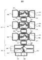
次に、処理室及び搬送機構を含む機械部の構成について、図2を用いて説明する。図2は、機械部を上面から俯瞰した図である。機械部は、大きく分けて、大気側機械部232と真空側機械部233に分けられる。大気側機械部232は、大気圧下で、ウェハが収納されているカセットから、ウェハを取り出したり収納したりといったウェハの搬送等を行う部分である。真空側機械部233は、大気圧から減圧された圧力下でウェハを搬送し、処理室内において処理を行う部分である。そして、大気側機械部232と真空側機械部233との間に、ウェハを内部に有した状態で圧力を大気圧と真空圧との間で上下させる部分であるロードロック211を備えている。
Next, the structure of the machine part including the processing chamber and the transport mechanism will be described with reference to FIG. FIG. 2 is an overhead view of the mechanical unit. The machine part is roughly divided into an atmosphere
大気側機械部232には、ロードポート201、202と、アライナー234と、大気ロボット203と、大気ロボットの可動エリアを覆う筐体204がある。このロードポート201、202に処理対象のウェハを収納したカセットが置かれる。そして、ウェハを保持することのできるハンドを有する大気ロボット203が、カセットの中に収納されているウェハを取り出して、ロードロック211の中へ搬送したり、逆に、ロードロック211の中からウェハを取り出し、カセットの中に収納したりする。この大気ロボット203は、ロボットアームを伸縮させたり、上下移動したり、旋回することができ、更に、筐体204の内部を水平移動することもできる。又、アライナー234とは、ウェハの向きを合わせるための機械である。但し、大気側機械部232は、一例であり、本発明の装置が、二つのロードポートを有する装置に限定されるものではなく、ロードポートの数が二つより少なくても、多くてもよい。加えて、本発明の装置が、一つの大気ロボットを有する装置に限定されるものではなく、複数の大気ロボットを有していてもよい。加えて、本発明の装置が、一つのアライナーを有する装置に限定されるものではなく、複数のアライナーを有していても良いし、アライナーが無くても良い。
The atmosphere
真空側機械部233には、処理室205、206、207、208、209、210と搬送室214、215、216と中間室212、213がある。処理室205、206、207、208、209、210は、ウェハに対してエッチングや成膜などの処理を行う部位である。これらは、ゲートバルブ222、223、226、227、230、231を介して、それぞれ搬送室214、215、216と接続されている。ゲートバルブ222、223、226、227、230、231は、開閉するバルブを有しており、処理室内部の空間と搬送室内部の空間を区切ったり、空間を繋げたりすることができる。
The vacuum
搬送室214、215、216には、真空ロボット217、218、219がそれぞれ備わっている。この真空ロボット217、218、219は、ウェハを保持することのできるハンドを備えており、ロボットアームが伸縮や旋回や上下移動することが出来、ウェハをロードロックに搬送したり、処理室に搬送したり、中間室に搬送したりする。
The
中間室212、213は、搬送室214、215、216の間に接続されており、ウェハを保持する機構を備えている。真空ロボット217、218、219が、この中間室212、213にウェハを置いたり、取り出したりすることで、搬送室間でウェハを受渡しすることができる。この中間室212、213は、ゲートバルブ224、225、228、229を介して、それぞれ搬送室214、215、216と接続している。このゲートバルブ224、225、228、229は、開閉するバルブを有しており、搬送室内部の空間と中間室内部の空間を区切ったり、空間を繋げたりすることができる。但し、真空側機械部233は、一例であり、本発明の装置が、六つの処理室を有する装置に限定されるものではなく、処理室数が六つより少なくても、多くてもよい。又、本実施例では、一つの搬送室に二つの処理室が接続される装置として説明するが、本発明の装置が、一つの搬送室に二つの処理室が接続された装置に限定されるものではなく、一つの搬送室に一つの処理室や三つ以上の処理室が接続された装置であってもよい。加えて、本発明の装置が、三つの搬送室を有する装置に限定されるものではなく、搬送室が三つより少なくても、多くてもよい。又、本実施例では搬送室と中間室の間にゲートバルブを備えた装置として説明するが、このゲートバルブはなくてもよい。
The
ロードロック211は、ゲートバルブ220、221を介して、それぞれ大気側機械部232と真空側機械部233に接続しており、ウェハを内部に有した状態で圧力を大気圧と真空圧との間で上下させることができる。
The
次に、機械部を側面から俯瞰した図3を用いて、ウェハを保持する構造について説明する。ウェハは、ロードロック305や、中間室310、315に保持することができる。これらロードロック305や中間室310、315は、複数のウェハをそれぞれ別々の保持できる構造(以降、保持段と呼ぶ)に保持する。物理的には、任意のウェハをどの保持段に置くことも可能であるが、運用として、一部の保持段には未処理ウェハのみ、又、別の一部の保持段には処理済ウェハのみを置くという運用が一般的である。これは、処理済ウェハには、処理に利用した腐食性ガスなどが付着しており、保持段にガスを残すことがある。このガスに未処理ウェハが触れると、ウェハに変質が起き、ウェハの品質を落としてしまうことがあるためである。よって、例えば、図3に示すようにロードロックに4段の保持段があったとした場合、2段を未処理ウェハ用の保持段、残り2段を処理済ウェハ用の保持段とする、というような運用が行われる。
なお、番号301はロードポートに置かれたカセットを、番号302は大気ロボットの可動エリアを覆う筐体を、番号303は大気ロボットを、番号307、312、318は搬送室を、番号308、313、317は真空ロボットを、番号304、306、309、311、314、316はゲートバルブを、番号319、320、321、322、323、324、325はウェハを、それぞれ意味する。
Next, a structure for holding a wafer will be described with reference to FIG. Wafers can be held in the
The
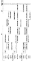
次に、本発明の半導体処理装置の動作制御システムの全体フローについて、図4を用いて説明する。なお、各ウェハが搬送ロボットを占有する時間は、処理工程に応じて異なる。処理室にて一回の処理を行って処理を完了する処理工程もあれば、複数回の処理を行って処理を完了する処理工程もある。更に、運用条件によっても異なることがある。ウェハの処理予定の処理室をいつでも自由に変える事が出来る運用条件もあれば、初期位置からウェハの搬送が開始されたら、処理予定の処理室を変えられない運用条件もある。ウェハの処理予定の処理室をいつでも自由に変えられる運用条件とは、処理に用いるガスの種類など処理条件が複数の処理室で同じであり、どの処理室で処理しても処理後のウェハの品質に違いが無い場合である。又、初期位置からウェハの搬送が開始されたら、処理予定の処理室を変えられない運用条件とは、処理に用いるガスの種類など処理条件が複数の処理室で同じだが、あるウェハに対して、一度処理予定の処理室が決定されたら、膜厚などそのウェハ特有の状態に応じて処理条件を微調整する運用が行われる場合や、処理に用いるガスの種類など処理条件が処理室によって異なる場合である。以下の説明にあたって、本実施例では、線形ツールにおいて、処理室にて一回の処理を行って処理を完了する一工程処理のみを扱うものとし、初期位置からウェハの搬送が開始されたら、処理予定の処理室を変えられない運用条件の下で搬送を行うものとする。 Next, the entire flow of the operation control system of the semiconductor processing apparatus of the present invention will be described with reference to FIG. The time for each wafer to occupy the transfer robot varies depending on the processing process. Some process steps complete a process by performing one process in the process chamber, and some process steps complete a process by performing a plurality of processes. Furthermore, it may differ depending on the operating conditions. There are operating conditions in which the processing chamber scheduled for wafer processing can be freely changed at any time, and there are operating conditions in which the processing chamber scheduled for processing cannot be changed once wafer transfer is started from the initial position. The operating conditions that allow the processing chamber to be processed for wafers to be freely changed at any time are the same in multiple processing chambers, such as the type of gas used for processing. This is the case when there is no difference in quality. In addition, once the wafer transfer is started from the initial position, the operating conditions in which the processing chamber to be processed cannot be changed are the same processing conditions such as the type of gas used for processing in a plurality of processing chambers. Once the processing chamber to be processed is determined, the processing conditions such as the type of gas used for processing differ depending on the processing chamber when the operation is performed to finely adjust the processing conditions according to the wafer-specific state such as the film thickness. Is the case. In the following description, in this embodiment, in the linear tool, it is assumed that only one-step processing is performed in which processing is performed once in the processing chamber and the processing is completed. It shall be transported under operating conditions where the planned processing chamber cannot be changed.
コンソール画面401から、利用者が制御モードの「手動」か「自動」を選択することができる。ここで、更に、各処理室において、ウェハが処理終了後に処理室内に待機する時間の許容値を設定することができる。選択された制御モードや処理室内に待機する時間の許容値によって、制御の計算処理が異なる。特に制御モードに関しては、制御モード設定部402が、指定された制御モードに応じて、制御の計算処理を切り替える。例えば、制御モードで「手動」が指定されれば、手動搬送先設定403が実行される。一方、制御モードが「自動」あれば、搬送先決定計算404が実行される。
From the
この演算処理403、404のいずれも、これから投入するウェハの搬送先処理室を決める処理であり、出力として搬送先情報405を出力する。この搬送先情報405と装置状態情報406をもとにして、動作命令計算407にて、動作命令408が算出され、機械部409がその動作命令408に基づいて、動作を行う。そして、動作を行う事で、装置内の状態が変化し、装置状態情報406が更新される。そして、再び、搬送先情報405と装置状態情報406をもとに動作命令計算407にて、動作命令408が算出され、機械部409は次の動作を行うことになる。
Both of the calculation processes 403 and 404 are processes for determining a transfer destination processing chamber of a wafer to be loaded from now on, and output
又、搬送先処理室を自動で決定する演算処理404は、新たな処理対象の搬送先を決定する時に、都度実行され、搬送先情報405を更新する。例えば、大気ロボットがあるウェハの搬送を終了し、新たなウェハに対する動作を行える状態になった時に、その新たなウェハの搬送先を計算する、といった具合である。
The
本発明は、制御モード「自動」の場合の効率的な制御方法に関するものであるので、以降、制御モード「自動」の場合の制御方法について説明する。よって以降、搬送先決定計算とは、搬送先計算404を指すものとする。
Since the present invention relates to an efficient control method in the case of the control mode “automatic”, hereinafter, the control method in the case of the control mode “automatic” will be described. Therefore, hereinafter, the transport destination determination calculation refers to the
まず、図4で示した動作命令計算407について、図5を用いて詳細に説明する。図5は、動作命令計算407の処理と入出力情報の関係を詳細に示した図である。動作命令計算407は、動作指示計算507と推定時間計算509と動作順序計算511と動作命令生成513の4つの演算処理から構成される。
First, the
動作指示計算507とは、装置状態情報501と搬送先情報502と動作指示ルール情報503を入力とし、動作指示情報508を出力するものである。装置状態情報501は、図12に例示するような情報であり、各部位の状態やそこにあるウェハの番号や処理の状態を表した情報である。例えば、「部位:ロードロック221_段1、状態:真空、ウェハ番号:W11、ウェハ状態:未処理」というデータは、ロードロック221の保持段の1段目の状態を示しており、ロードロックの状態は真空状態、ウェハ番号W11のウェハが保持されており、そのW11は未処理ウェハであるということを意味している。搬送先情報502は、図13に例示するような情報であり、各ウェハの搬送先処理室を表した情報である。動作指示ルール情報503は、図14に例示するような情報であり、動作指示と、その動作指示を行う条件を記述した情報である。例えば、「ロードロック211から中間室212へ搬送」という動作指示は、「ロードロック211に搬送先が処理室205、206以外の未処理ウェハがあり、かつ、ロードロック211が真空状態である」「中間室212に空きの保持段がある」「真空ロボット217の少なくとも片方のハンドが待機状態である」という条件が揃ったときに指示が行われるということを意味する。動作指示情報508は、図15に例示するような情報であり、搬送の動作指示と搬送対象のウェハ番号と動作順序番号と各動作指示の順序を持つ情報である。動作指示計算507では、装置状態情報501、搬送先情報502を参照し、動作指示ルール情報503の動作指示条件が全て満たされた動作指示を抽出し、その動作指示を動作指示情報508として出力する。
The
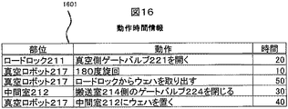
推定時間計算509とは、装置状態情報501と搬送先情報502と動作時間情報504と動作指示情報508を用いて、推定時間情報510を出力する処理である。動作時間情報504は、図16に例示するような情報であり、搬送ロボットやロードロックといった装置内の部位が動作する際に必要な時間を表した情報である。推定時間情報510とは、図17に例示するような情報であり、動作順序ごとに、各処理室における処理終了後の処理室待機推定時間とスループットを表す情報である。
ここで、図5で示した推定時間計算を図6のフローチャートを用いて説明する。まず処理ステップ601で次処理予定ウェハの現在位置を取得する。次に処理ステップ602で、次処理予定ウェハの現在位置から処理室までの搬送経路を抽出する。ステップ603で搬送経路上にある任意の部位に対して、動作時間情報を用いて搬送時間を推定する。推定した搬送時間により、処理終了後のウェハ待機時間を推定する。本実施例では、搬送時間を計算する一例としてシミュレーションを用いている。図17で示した情報は、シミュレーションにより計算された結果である。複数の動作順序を想定して、それぞれの処理室への搬送時間及びウエハの処理が終了してから取り出されるまでの処理室待機時間、スループットを推定したものである。図7は各動作順序1〜3により動作指示をした場合のガントチャートを表した図である。ガントチャートとは、横軸に時間をとり、各部位が動作している時間帯をブロックで表現したものである。図7は、シミュレーションにより計算された3通りの動作順序を示している。処理室207,208でのウェハの処理及び処理済ウェハの搬出、搬入を真空ロボット218の動作、中間室212,213との関係で示している。実際には、シミュレーションで計算されるのは3通りに限らず、多数の動作の組み合わせについてシミュレーションを行うことができる。
装置のスループットは単位時間当たりの処理枚数により計算される。図7から分かるように、各動作の終了時間と処理した枚数からスループットが計算される。図7のガントチャートで処理した枚数は2枚であるため、各動作順序のスループットは、処理枚数を動作終了までの時間で割ることにより、動作順序1が0.0036、動作順序2が0.0032、動作順序3が0.003と計算できる。
Here, the estimation time calculation shown in FIG. 5 will be described with reference to the flowchart of FIG. First, in processing
The throughput of the apparatus is calculated based on the number of processed sheets per unit time. As can be seen from FIG. 7, the throughput is calculated from the end time of each operation and the number of processed sheets. Since the number of sheets processed in the Gantt chart of FIG. 7 is two, the throughput of each operation order is 0.0036 for the
シミュレーション以外に搬送時間を計算する例として、各動作時間の合計値を用いてもよい。また、搬送時間を計算する場合に、既に他のウェハに占有されている部位がある場合、その動作が完了するまでの時間を追加することにより、搬送時間としても良い。 As an example of calculating the conveyance time other than the simulation, the total value of each operation time may be used. Further, when calculating the transfer time, if there is a part already occupied by another wafer, the transfer time may be set by adding the time until the operation is completed.
動作順序計算511とは、推定時間情報510と許容値情報505とを用いて、動作順序情報512を計算する処理である。許容値情報505は図18に例示されるような情報であり、ウェハが処理後に処理室内で待機することを許容される時間を処理室ごとに表した情報である。動作順序情報は図19に例示されるような情報であり、動作順序と動作指示と搬送対象を表す情報である。
The operation order calculation 511 is a process for calculating the
推定時間情報から、処理室待機時間が許容値内となる動作順序の内、最もスループットが高くなる動作順序を図17と図18に例示した情報においては、動作順序1を出力する。
From the estimated time information, the
尚、シミュレーションの結果を考慮するとスループット向上のために、下記のような動作を行わせても良い。すなわち、ウエハを許容値内で処理室より搬出することができる場合には、理室内に処理済のウェハがあり、処理室と接続された搬送機構部において、該搬送機構部と接続された中間室内に次搬送先が該処理室である未処理のウェハがある状況では、未処理のウェハを、処理室内にある処理済のウエハに優先して搬出することでスループット向上が図られる。 In consideration of the simulation result, the following operation may be performed in order to improve the throughput. That is, when the wafer can be unloaded from the processing chamber within the allowable value, there is a processed wafer in the processing chamber, and in the transfer mechanism connected to the processing chamber, an intermediate connected to the transfer mechanism. In a situation where there is an unprocessed wafer whose next transfer destination is the processing chamber in the chamber, throughput can be improved by unloading the unprocessed wafer in preference to the processed wafer in the processing chamber.
また、処理室までの搬送時間を推定し、推定された搬送時間が、処理済であるウェハの待機時間の許容値を超過した場合に、ウェハの次搬送先である室が受け入れ可能な状態である範囲内で、処理済であるウェハの搬出を、未処理であるウエハの搬出に優先することで、ウェハの待機時間の許容値を超過を回避してもよい。また、実際の動作においては、ウェハの待機時間の許容値を超えてしまうような場合は、動作を止めず(デッドロックとせず)に、多少の許容時間超過しても可能な限り処理済であるウェハの搬出を、未処理であるウエハの搬出に優先するしてもよい。 In addition, the transfer time to the processing chamber is estimated, and when the estimated transfer time exceeds the allowable value of the waiting time of a processed wafer, the next transfer destination chamber of the wafer is in an acceptable state. Within a certain range, priority may be given to unloading processed wafers over unprocessed wafers to avoid exceeding the allowable value of the wafer standby time. In actual operation, if the allowable value of the waiting time of the wafer is exceeded, the operation is not stopped (not deadlocked) and the processing is completed as much as possible even if some allowable time is exceeded. You may give priority to unloading a certain wafer over unprocessed wafers.
次に、動作命令生成513とは、動作指示情報508と動作順序情報512と動作シーケンス情報506を入力とし、動作命令514を出力し、機械部へ動作命令を伝達するものである。動作シーケンス情報506は、図20に例示するような情報である。これは、動作指示について、大気ロボットや真空ロボットの動作や、ロードロックや中間室や処理室のゲートバルブの開閉動作や、ロードロックの真空引きを行うポンプの動作等、各部位の具体的な動作内容を記述したものであり、動作順序情報に記された番号の若い順より動作を実行するという事を意味している。この動作シーケンス情報506は、各動作指示について、各々定義されるものである。又、動作を開始できる状態であれば、若い番号の動作が完了していなくとも、動作を開始しても良い。
Next, the
動作命令生成513では、動作指示情報508にある動作指示について、動作シーケンス情報506から該当する動作指示の動作シーケンスデータを動作順序情報512の番号の若い順に抽出し、動作シーケンスデータの番号の若い順より、動作命令として機械部へ伝達する。
In the
次に、図4で示した搬送先決定計算404における一実施例として、図8を用いて説明する。搬送先決定計算404は、割当対象処理室情報計算804、搬送先計算806の2つの演算処理からなる。
Next, an example of the transport
割当対象処理室計算804とは、処理室情報801と装置状態情報802とを入力とし、割当対象処理室情報805を出力するものである。処理室情報801とは、図21に例示するような情報であり、各処理室の稼働状況を表す情報である。状態が「稼働」であれば、処理を行う事が出来る状態を意味し、状態が「停止」であれば、処理を行う事ができない状態を意味する。割当対象処理室計算804は、搬送が可能な処理室を抽出する処理である。割当対象処理室情報805とは、図22に例示するような情報であり、ウェハの搬送先を計算する際に、搬送先の割当候補となる処理室をリストアップした情報である。一つの例としては、状態が「稼動」である任意の処理室を割当対象処理室とする手法がある。この抽出は一例であり、他の抽出方法で割当対象処理室を抽出しても良い。
The allocation target
搬送先計算806とは、処理対象情報803と搬送先情報801と割り当て対象処理室情報805を入力とし、搬送先情報807を更新する。処理対象情報803とは、図23に例示するような情報であり、処理対象のウェハを識別するウェハ番号が記述された情報である。
The transport destination calculation 806 receives the
次に、図8で示した搬送先計算806の詳細な計算処理を図9のフローチャートを用いて説明する。搬送先計算806は、これから装置内へ投入されるウェハに対し、搬送先の処理室を決める処理である。まず、処理ステップ901で、これから装置内へ投入されるウェハのウェハ番号を取得する。具体的な処理としては、処理対象情報から、搬送先情報にないウェハ番号のデータを抽出し、その中から最もウェハ番号の小さいものを取得し、これをこれから装置内へ投入するウェハとする。次に、処理ステップ902で、搬送先情報から最もウェハ番号の大きいデータを抽出し、そのデータの搬送先の処理室を取得する。そして、次に、処理ステップ903で、割り当て対象処理室情報にある全ての処理室番号を抽出し、その中から処理ステップ902で取得した処理室番号より大きい処理室番号があれば、その処理ステップ902で取得した処理室番号より大きい処理室番号の中で最も小さい処理室番号の処理室を、搬送先処理室とする。もし、処理ステップ902で取得した処理室番号より大きい処理室番号がなければ、割り当て対象処理室情報にある全ての処理室番号のうち、最も小さい処理室番号の処理室を、搬送先処理室とする。最後に、処理ステップ904で、処理ステップ901で取得したウェハの搬送先処理室として、処理ステップ903で取得した搬送先処理室を割り当て、搬送先情報に追加する。但し、本実施例で説明した搬送先を決定するアルゴリズムは一例であって、本発明がこのアルゴリズムに限定されるものではない。未処理ウェハ枚数情報をもとに計算された割り当て対象処理室情報を入力として、ウェハの搬送先を計算するアルゴリズムであれば、他のアルゴリズムでも良い。
Next, detailed calculation processing of the transport destination calculation 806 shown in FIG. 8 will be described using the flowchart of FIG. The transfer destination calculation 806 is a process for determining a transfer destination processing chamber for a wafer to be loaded into the apparatus. First, in
たとえば、図4で示した搬送先計算404におけるもう一つの実施例について、図10のフローを用いて説明する。まず、処理ステップ1001で、これから装置内へ投入されるウェハのウェハ番号を取得する。具体的な処理としては、処理対象情報から、搬送先情報にないウェハ番号のデータを抽出し、その中から最もウェハ番号の小さいものを取得し、これをこれから装置内へ投入するウェハとする。次に、処理ステップ1002で、搬送先情報から最もウェハ番号の大きいデータを抽出し、そのデータの搬送先の処理室を取得する。そして、次に、処理ステップ1003で、割り当て対象処理室情報にある全ての処理室番号を抽出し、各処理室を搬送先として割り当てた場合のシミュレーションを実施する。図7と同様にシミュレーションの結果として、各搬送先ごとに処理終了後の処理室内のウェハ待機時間とスループットを計算し、待機時間が許容値以内の搬送先の内、最もスループットが高い処理室を取得する。最後に、処理ステップ1004で、処理ステップ1001で取得したウェハの搬送先処理室として、処理ステップ1003で取得した搬送先処理室を割り当て、搬送先情報に追加する。すなわち、搬送先を決定する際に、処理室での待機時間を推定し、許容値以内に収まる搬送先を出力するように計算する方法である。
For example, another embodiment of the
ここで、図6で説明した装置状態情報501や、図8で説明した処理室情報801は、機械部をモニターした情報であり、次々刻々と更新され、又、処理対象情報803は、処理対象のウェハが入ったカセットがロードポートに到着した時に、ホストコンピュータよりダウンロードされるものである。
Here, the
最後に、図1に示したコンソール端末103の画面について、図11を用いて説明する。コンソール端末103は、入力部と出力部があり、入力部としてキーボードやマウス、タッチペン等が備わっている。又、出力部として画面が備わっている。その画面には、制御方法を選択するエリア1101と装置状態の概要を表示するエリア1102と装置状態の詳細データを表示するエリア1103とがある。制御方法を選択するエリア1101には、制御方法として「手動」「自動」を選択できるようになっている。更に、制御方法として「自動」を選択すると、処理室不確実対応の有無を選択出来るようになる。また、処理済みウェハの待機時間許容値も処理室ごとに入力することが可能である。装置状態の概要を表示するエリア1102には、どのウェハがどこにあるのか、簡便に把握できるよう、装置とウェハの位置をビジュアルに表示する。ウェハが移動すると、ウェハの表示位置がそれに応じて、変更される。図中のエリア1102内の円形で記載したものがウェハ1104を表すものである。又、装置状態の詳細データを表示するエリア1103には、装置内にあるウェハの詳細な状態や処理室や搬送機構の詳細な状態を表示する。
Finally, the screen of the
101:機械部、
102:動作制御部、
103:コンソール端末、
104:演算部、
105:記憶部、
106:制御モード設定部、
107:動作指示計算部、
108:割当対象処理室計算部、
109:搬送先計算部、
110:搬送時間推定計算部、
111:装置状態情報、
112:処理対象情報、
113:処理室情報、
114:搬送先情報、
115:動作指示情報、
116:動作指示ルール情報、
117:動作シーケンス情報、
118:割当対象処理室情報、
119:推定時間情報、
120:待機時間許容値情報、
121:ホストコンピュータ、
122:ネットワーク、
201、202:ロードポート、
203:大気ロボット、
204:筐体、
205、206、207、208、209、210:処理室、
211:ロードロック、
212、213:中間室、
214、215、216:搬送室、
217、218、219:真空ロボット、
220、221、222、223、224、225、226、227、228、229、230、231:ゲートバルブ、
232:大気側機械部、
233:真空側機械部、
224:アライナー、
301:カセット、
302:筐体、
303:大気ロボット、
307、312、318:搬送室、
308、313、317:真空ロボット、
304、306、309、311、314、316:ゲートバルブ、
319、320、321、322、323、324、325:ウェハ、
402:制御モード設定部処理、
403:手動搬送先設定、
404:搬送先決定計算、
407:動作命令計算、
408:動作命令、
507:動作指示計算、
509:推定時間計算、
511:動作順序計算、
513:動作命令生成、
804:割り当て対象処理室情報計算、
806:搬送先計算、
601、602、603、901、902、903、904、1001、1002、1003、1004:処理ステップ、
1101:制御方法選択エリア、
1102:装置状態概要表示エリア、
1103:装置状態詳細データ表示エリア、
1104:ウェハ。
101: Machine part
102: Operation control unit,
103: Console terminal,
104: arithmetic unit,
105: Storage unit,
106: Control mode setting unit,
107: Operation instruction calculation unit,
108: Assignment target processing room calculation unit,
109: Transport destination calculation unit,
110: Transport time estimation calculation unit,
111: Device status information
112: processing target information,
113: Processing chamber information,
114: transport destination information,
115: operation instruction information,
116: Operation instruction rule information,
117: Operation sequence information,
118: Allocation target processing room information,
119: Estimated time information,
120: Waiting time tolerance information,
121: Host computer
122: Network
201, 202: load port,
203: atmospheric robot,
204: housing,
205, 206, 207, 208, 209, 210: processing chamber,
211: Load lock,
212, 213: Intermediate room,
214, 215, 216: transfer chamber,
217, 218, 219: vacuum robot,
220, 221, 222, 223, 224, 225, 226, 227, 228, 229, 230, 231: gate valve,
232: Atmosphere side machine part,
233: Vacuum side machine part,
224: Aligner
301: cassette
302: Case,
303: atmospheric robot,
307, 312, 318: transfer chamber,
308, 313, 317: Vacuum robot,
304, 306, 309, 311, 314, 316: gate valve,
319, 320, 321, 322, 323, 324, 325: wafer,
402: Control mode setting unit processing,
403: Manual transport destination setting,
404: transport destination determination calculation,
407: Operation command calculation,
408: Operation command,
507: Operation instruction calculation,
509: Estimated time calculation,
511: operation order calculation,
513: Operation command generation,
804: Allocation target processing room information calculation,
806: Transport destination calculation,
601, 602, 603, 901, 902, 903, 904, 1001, 1002, 1003, 1004: processing steps,
1101: Control method selection area,
1102: Device status summary display area,
1103: Device status detailed data display area,
1104: Wafer.
Claims (11)
真空側に配置され、前記被処理体の受け渡し及び搬送を行う真空ロボットを具備してなる複数の搬送機構部と、
前記搬送機構部に接続された前記被処理体に所定の処理を施す複数の処理室と、
前記搬送機構部間を連結して前記被処理体を中継載置する中間室と、
前記ロードロックと前記中間室に設けられた複数の前記被処理体を保持する保持機構部と、
前記被処理体の受け渡しおよび搬送を制御する制御部と、を備えた真空処理装置であって、
前記制御部は、前記被処理体が処理終了後に前記処理室内に待機できる時間に基づいて、前記被処理体を搬送する搬送室及び、前記搬送機構部の動作順序を決定することを特徴とする真空処理装置。 A load lock that takes the workpiece placed on the atmosphere side into the vacuum side,
A plurality of transfer mechanism units provided on a vacuum side and provided with a vacuum robot for delivering and transferring the object to be processed;
A plurality of processing chambers for performing a predetermined process on the object to be processed connected to the transport mechanism;
An intermediate chamber that connects between the transfer mechanisms and relays the object to be processed;
A holding mechanism for holding the load lock and the plurality of objects to be processed provided in the intermediate chamber;
A vacuum processing apparatus comprising: a control unit that controls delivery and conveyance of the object to be processed;
The control unit determines an operation order of a transfer chamber for transferring the object to be processed and a transfer mechanism unit based on a time during which the object to be processed can stand by in the processing chamber after the processing is completed. Vacuum processing equipment.
前記被処理体が処理終了後に前記処理室内に待機できる時間の許容値を入力することができる入力部を備え、該入力部から前記被処理体の前記処理室内における待機時間の許容値に基づいて、前記制御部は、前記被処理体の搬送動作を決定することを特徴とする真空処理装置。 The vacuum processing apparatus according to claim 1,
An input unit capable of inputting an allowable value of a time during which the object to be processed can wait in the processing chamber after completion of processing, and based on an allowable value of the waiting time of the object to be processed in the processing chamber from the input unit; The vacuum processing apparatus, wherein the control unit determines a transfer operation of the object to be processed.
前記制御部は、シミュレーションにより、前記被処理体を処理するスループットを算出し、該スループットに基づいて、前記被処理体を搬送する搬送室及び前記搬送機構部の動作順序を決定することを特徴とする真空処理装置。 The vacuum processing apparatus according to claim 1,
The control unit calculates a throughput for processing the object to be processed by simulation, and determines an operation order of the transfer chamber and the transfer mechanism unit for transferring the object to be processed based on the throughput. Vacuum processing equipment.
前記制御部は、前記被処理体が処理終了後に前記処理室内に待機できる時間よりも早く、前記被処理体を搬出することができる場合には、前記被処理体のうち、前記処理室内に処理済の被処理体があり、該処理室と接続された前記搬送機構部において、該搬送機構部と接続された前記中間室内に次搬送先が該処理室である未処理の被処理体がある状況では、未処理の被処理体を、前記処理室内にある処理済の被処理体に優先して搬出することを特徴とする真空処理装置。 The vacuum processing apparatus according to claim 1,
When the object to be processed can be carried out earlier than the time when the object to be processed can stand by in the processing chamber after the processing is completed, the control unit performs processing in the processing chamber among the objects to be processed. In the transfer mechanism unit connected to the processing chamber, there is an unprocessed target object whose next transfer destination is the processing chamber in the intermediate chamber connected to the transfer mechanism unit. In a situation, the vacuum processing apparatus is characterized in that an unprocessed object to be processed is carried out in preference to a processed object in the processing chamber.
前記制御部は、前記処理室までの搬送時間を推定し、推定された搬送時間が、処理済である前記被処理体の待機時間の許容値を超過した場合に、前記被処理体の次搬送先である室が前記被処理体を受け入れ可能な状態である範囲内で、前記搬送機構が処理済である前記被処理体の搬出を、未処理である前記被処理体の搬出に優先することを特徴とする真空処理装置。 The vacuum processing apparatus according to claim 2,
The control unit estimates a transfer time to the processing chamber, and when the estimated transfer time exceeds an allowable value of a waiting time of the processed object that has been processed, the next transfer of the processed object Priority is given to unloading the object to be processed that has been processed by the transport mechanism over unloading the object to be processed within a range in which the previous chamber can receive the object to be processed. A vacuum processing apparatus.
前記制御部は、複数の搬送機構部の動作順序について、該被処理体が処理終了後に前記処理室内に待機する時間を算出し、算出された時間が前記被処理体が処理終了後に前記処理室内に待機できる時間を超えないような前記搬送機構部の動作順序を選択することを特徴とする真空処理装置。 The vacuum processing apparatus according to claim 1,
The control unit calculates a time during which the object to be processed waits in the processing chamber after the processing is completed with respect to an operation order of the plurality of transport mechanism units, and the calculated time is calculated in the processing chamber after the object is processed. The vacuum processing apparatus is characterized in that the operation order of the transport mechanism unit is selected so as not to exceed the time that can be waited.
前記被処理体が処理終了後に前記処理室内に待機できる時間を設定するステップと、
設定された時間に基づいて、前記被処理体を搬送する搬送室及び前記搬送機構部の動作順序を決定するステップと、を備えることを特徴とする真空処理方法。 A plurality of transfer mechanism units including a load lock that takes in an object to be processed placed on the atmosphere side into the vacuum side, a vacuum robot that is disposed on the vacuum side and delivers and conveys the object to be processed, and the transfer A plurality of processing chambers for performing a predetermined process on the object to be processed connected to a mechanism part; an intermediate chamber for connecting the transfer mechanism part and placing the object to be relayed; the load lock; A vacuum processing method for processing the object to be processed in a vacuum processing apparatus including a plurality of the object to be processed provided in a chamber,
Setting a time during which the object to be processed can wait in the processing chamber after the processing is completed;
And a step of determining an operation order of a transfer chamber for transferring the object to be processed and the transfer mechanism unit based on a set time.
シミュレーションにより前記被処理体を処理するスループットを算出するステップと
該スループットに基づいて、前記被処理体を搬送する搬送室及び前記搬送機構部の動作順序を決定するステップとを備えることを特徴とする真空処理方法。 In the vacuum processing method of Claim 7,
A step of calculating a throughput for processing the object to be processed by simulation, and a step of determining an operation order of the transfer chamber and the transfer mechanism unit for transferring the object to be processed based on the throughput. Vacuum processing method.
前記前記被処理体を搬送する搬送室及び前記搬送機構部の動作順序を決定するステップは、前記被処理体が処理終了後に前記処理室内に待機できる時間よりも早く、前記被処理体を搬出することができる場合には、前記被処理体のうち、前記処理室内に処理済の被処理体があり、該処理室と接続された前記搬送機構部において、該搬送機構部と接続された前記中間室内に次搬送先が該処理室である未処理の被処理体がある状況では、未処理の被処理体を、前記処理室内にある処理済の被処理体に優先して搬出する真空処理方法。 In the vacuum processing method of Claim 7,
The step of determining the operation order of the transfer chamber for transferring the object to be processed and the transfer mechanism unit unloads the object to be processed earlier than the time when the object to be processed can stand by in the process chamber after the processing is completed. If it is possible, there is a processed object in the processing chamber among the objects to be processed, and the intermediate mechanism connected to the transfer mechanism unit in the transfer mechanism unit connected to the process chamber. In a situation where there is an unprocessed target object whose next transfer destination is the processing chamber in the room, a vacuum processing method for unloading the unprocessed target object in preference to the processed target object in the process chamber .
前記被処理体を搬送する搬送室及び前記搬送機構部の動作順序を決定するステップは、前記処理室までの搬送時間を推定し、推定された搬送時間が、処理済である前記被処理体の待機時間の許容値を超過した場合に、前記被処理体の次搬送先である室が前記被処理体を受け入れ可能な状態である範囲内で、前記搬送機構が既処理済である前記被処理体の搬出を、未処理である前記被処理体の搬出に優先することを特徴とする真空処理方法。 In the vacuum processing method of Claim 7,
The step of determining the operation order of the transfer chamber for transferring the object to be processed and the transfer mechanism unit estimates the transfer time to the process chamber, and the estimated transfer time of the object to be processed is processed. The processing target that has already been processed within the range in which the chamber that is the next transfer destination of the target object can receive the target object when the allowable value of the waiting time is exceeded A vacuum processing method characterized in that unloading of the body is given priority over unloading of the object to be processed.
前記被処理体を搬送する搬送室及び前記搬送機構部の動作順序を決定するステップは、複数の搬送機構部の動作順序について、該被処理体が処理終了後に前記処理室内に待機する時間を算出し、算出された時間が前記被処理体が処理終了後に前記処理室内に待機できる時間を超えないような前記搬送機構部の動作順序を選択することを特徴とする真空処理方法。 In the vacuum processing method of Claim 7,
The step of determining the operation order of the transfer chamber for transferring the object to be processed and the transfer mechanism unit calculates the time during which the object to be processed waits in the process chamber after the processing is completed for the operation order of the plurality of transfer mechanism units. And selecting an operation order of the transport mechanism so that the calculated time does not exceed a time during which the object to be processed can wait in the processing chamber after the processing is completed.
Priority Applications (4)
| Application Number | Priority Date | Filing Date | Title |
|---|---|---|---|
| JP2012224685A JP6002532B2 (en) | 2012-10-10 | 2012-10-10 | Vacuum processing apparatus and vacuum processing method |
| US14/023,874 US20140099176A1 (en) | 2012-10-10 | 2013-09-11 | Vacuum processing apparatus and vacuum processing method |
| KR1020130110440A KR101531985B1 (en) | 2012-10-10 | 2013-09-13 | Vacuum processing appartus and vacuum processing method |
| TW102133693A TWI518833B (en) | 2012-10-10 | 2013-09-17 | Vacuum processing apparatus and vacuum processing method |
Applications Claiming Priority (1)
| Application Number | Priority Date | Filing Date | Title |
|---|---|---|---|
| JP2012224685A JP6002532B2 (en) | 2012-10-10 | 2012-10-10 | Vacuum processing apparatus and vacuum processing method |
Publications (2)
| Publication Number | Publication Date |
|---|---|
| JP2014078576A JP2014078576A (en) | 2014-05-01 |
| JP6002532B2 true JP6002532B2 (en) | 2016-10-05 |
Family
ID=50432787
Family Applications (1)
| Application Number | Title | Priority Date | Filing Date |
|---|---|---|---|
| JP2012224685A Active JP6002532B2 (en) | 2012-10-10 | 2012-10-10 | Vacuum processing apparatus and vacuum processing method |
Country Status (4)
| Country | Link |
|---|---|
| US (1) | US20140099176A1 (en) |
| JP (1) | JP6002532B2 (en) |
| KR (1) | KR101531985B1 (en) |
| TW (1) | TWI518833B (en) |
Families Citing this family (14)
| Publication number | Priority date | Publication date | Assignee | Title |
|---|---|---|---|---|
| WO2014025918A1 (en) * | 2012-08-08 | 2014-02-13 | Applied Materials, Inc | Linked vacuum processing tools and methods of using the same |
| JP6298318B2 (en) * | 2014-02-25 | 2018-03-20 | 株式会社Screenホールディングス | Substrate processing method and substrate processing apparatus |
| JP6297001B2 (en) * | 2014-03-19 | 2018-03-20 | キヤノン株式会社 | Lithographic apparatus, lithography method, lithography system, program, and article manufacturing method |
| US10520932B2 (en) * | 2014-07-03 | 2019-12-31 | Taiwan Semiconductor Manufacturing Co., Ltd | Transport system and method |
| AU2015100138A4 (en) * | 2015-01-12 | 2015-03-05 | Macau University Of Science And Technology | Method for Scheduling Single-arm Cluster Tools with Wafer Revisiting and Residency Time Constraints |
| US9618930B1 (en) * | 2015-09-20 | 2017-04-11 | Macau University Of Science And Technology | Scheduling start-up process for time-constrained single-arm cluster tools |
| US11482434B2 (en) | 2016-10-18 | 2022-10-25 | Belting E-Town Semiconductor Technology Co., Ltd | Systems and methods for workpiece processing |
| US10580672B2 (en) * | 2016-10-18 | 2020-03-03 | Mattson Technology, Inc. | Systems and methods for workpiece processing |
| US10043693B1 (en) * | 2017-06-06 | 2018-08-07 | Applied Materials, Inc. | Method and apparatus for handling substrates in a processing system having a buffer chamber |
| KR20200072060A (en) * | 2018-12-12 | 2020-06-22 | 세메스 주식회사 | Apparatus and method for treating substrate |
| KR102315878B1 (en) * | 2018-12-26 | 2021-10-21 | 세메스 주식회사 | A transfer unit controller and a substrate processing apparatus |
| WO2020161873A1 (en) * | 2019-02-07 | 2020-08-13 | 株式会社日立ハイテクノロジーズ | Method for operating vacuum processing device |
| CN111446186B (en) * | 2020-03-27 | 2023-02-14 | 北京北方华创微电子装备有限公司 | Material classification scheduling method for preventing scheduling deadlock |
| CN112582320B (en) * | 2020-12-08 | 2024-02-09 | 北京晶亦精微科技股份有限公司 | Method and device for alternately dispatching wafers and wafer cleaning and conveying system |
Family Cites Families (39)
| Publication number | Priority date | Publication date | Assignee | Title |
|---|---|---|---|---|
| JP3654597B2 (en) * | 1993-07-15 | 2005-06-02 | 株式会社ルネサステクノロジ | Manufacturing system and manufacturing method |
| US6201999B1 (en) * | 1997-06-09 | 2001-03-13 | Applied Materials, Inc. | Method and apparatus for automatically generating schedules for wafer processing within a multichamber semiconductor wafer processing tool |
| US6480756B1 (en) * | 1999-10-12 | 2002-11-12 | Taiwan Semiconductor Manufacturing Co., Ltd. | Real-time monitor mechanism for heterogeneous production lines |
| US6889105B2 (en) * | 2001-05-16 | 2005-05-03 | Dainippon Screen Mfg. Co., Ltd. | Scheduling method and program for a substrate processing apparatus |
| JP3758992B2 (en) * | 2001-05-16 | 2006-03-22 | 大日本スクリーン製造株式会社 | Substrate processing apparatus schedule creation method and program thereof |
| JP4657528B2 (en) * | 2001-09-05 | 2011-03-23 | 東京エレクトロン株式会社 | Processing system and processing method |
| JP3916473B2 (en) * | 2002-01-31 | 2007-05-16 | 東京エレクトロン株式会社 | Substrate processing apparatus and substrate processing method |
| JP2003241818A (en) * | 2002-02-19 | 2003-08-29 | Dainippon Screen Mfg Co Ltd | Schedule creation method for substrate treatment system and its program |
| JP4283559B2 (en) * | 2003-02-24 | 2009-06-24 | 東京エレクトロン株式会社 | Conveying apparatus, vacuum processing apparatus, and atmospheric pressure conveying apparatus |
| BRPI0418164A (en) * | 2003-12-24 | 2007-06-19 | Nippon Steel Corp | production scheduling creation device and method, production process control device and method, computer program and computer readable recording medium |
| US20050233477A1 (en) * | 2004-03-05 | 2005-10-20 | Tokyo Electron Limited | Substrate processing apparatus, substrate processing method, and program for implementing the method |
| US7246985B2 (en) * | 2004-04-16 | 2007-07-24 | Axcelis Technologies, Inc. | Work-piece processing system |
| JP4557986B2 (en) * | 2004-11-24 | 2010-10-06 | 株式会社日立国際電気 | Substrate processing apparatus and semiconductor device manufacturing method |
| US8078311B2 (en) * | 2004-12-06 | 2011-12-13 | Tokyo Electron Limited | Substrate processing apparatus and substrate transfer method adopted in substrate processing apparatus |
| JP4353903B2 (en) * | 2005-01-07 | 2009-10-28 | 東京エレクトロン株式会社 | Cluster tool processing system |
| JP4925650B2 (en) * | 2005-11-28 | 2012-05-09 | 東京エレクトロン株式会社 | Substrate processing equipment |
| DE102006025407A1 (en) * | 2006-05-31 | 2007-12-06 | Advanced Micro Devices, Inc., Sunnyvale | Method and system for dynamically changing the transport sequence in a cluster plant |
| KR100847888B1 (en) * | 2006-12-12 | 2008-07-23 | 세메스 주식회사 | Apparatus for fabricating semiconductor device |
| US20080216077A1 (en) * | 2007-03-02 | 2008-09-04 | Applied Materials, Inc. | Software sequencer for integrated substrate processing system |
| US20090029502A1 (en) * | 2007-07-24 | 2009-01-29 | Applied Materials, Inc. | Apparatuses and methods of substrate temperature control during thin film solar manufacturing |
| DE102007046848A1 (en) * | 2007-09-29 | 2009-04-02 | Advanced Micro Devices, Inc., Sunnyvale | Method and system for controlling the transport sequences in a process plant by means of a predictive mode |
| JP5330721B2 (en) * | 2007-10-23 | 2013-10-30 | オルボテック エルティ ソラー,エルエルシー | Processing apparatus and processing method |
| US8731706B2 (en) * | 2008-09-12 | 2014-05-20 | Hitachi High-Technologies Corporation | Vacuum processing apparatus |
| JP4707749B2 (en) * | 2009-04-01 | 2011-06-22 | 東京エレクトロン株式会社 | Substrate replacement method and substrate processing apparatus |
| JP5433290B2 (en) * | 2009-04-20 | 2014-03-05 | 東京エレクトロン株式会社 | Substrate storage method and control device |
| JP5358366B2 (en) * | 2009-09-14 | 2013-12-04 | 東京エレクトロン株式会社 | Substrate processing apparatus and method |
| JP2011091334A (en) * | 2009-10-26 | 2011-05-06 | Ulvac Japan Ltd | Substrate treatment apparatus |
| JP5282021B2 (en) * | 2009-12-14 | 2013-09-04 | 株式会社日立ハイテクノロジーズ | Semiconductor processing system and semiconductor processing method |
| JP5586271B2 (en) * | 2010-03-02 | 2014-09-10 | 株式会社日立ハイテクノロジーズ | Vacuum processing apparatus and program |
| KR101331288B1 (en) * | 2010-08-06 | 2013-11-20 | 도쿄엘렉트론가부시키가이샤 | Substrate processing system, transfer module, substrate processing method, and method for manufacturing semiconductor element |
| JP2012114259A (en) * | 2010-11-25 | 2012-06-14 | Lapis Semiconductor Co Ltd | System and method for substrate processing |
| JP5476337B2 (en) * | 2011-05-26 | 2014-04-23 | 株式会社日立ハイテクノロジーズ | Vacuum processing apparatus and program |
| JP5592863B2 (en) * | 2011-11-02 | 2014-09-17 | 株式会社日立ハイテクノロジーズ | Vacuum processing apparatus and method for conveying object to be processed |
| CN104024861B (en) * | 2012-01-05 | 2015-11-25 | 株式会社日立高新技术 | Agent treated method in automatic analysing apparatus and automatic analysing apparatus |
| JP2013143413A (en) * | 2012-01-10 | 2013-07-22 | Hitachi High-Technologies Corp | Vacuum processing apparatus |
| JP2013143513A (en) * | 2012-01-12 | 2013-07-22 | Hitachi High-Technologies Corp | Vacuum processing apparatus |
| JP6013792B2 (en) * | 2012-06-12 | 2016-10-25 | 東京エレクトロン株式会社 | Substrate transport method and substrate transport apparatus |
| JP5981307B2 (en) * | 2012-11-07 | 2016-08-31 | 東京エレクトロン株式会社 | Processing method and processing apparatus |
| JP6216530B2 (en) * | 2013-03-29 | 2017-10-18 | 株式会社日立ハイテクノロジーズ | Operation method of vacuum processing equipment |
-
2012
- 2012-10-10 JP JP2012224685A patent/JP6002532B2/en active Active
-
2013
- 2013-09-11 US US14/023,874 patent/US20140099176A1/en not_active Abandoned
- 2013-09-13 KR KR1020130110440A patent/KR101531985B1/en active IP Right Grant
- 2013-09-17 TW TW102133693A patent/TWI518833B/en active
Also Published As
| Publication number | Publication date |
|---|---|
| TWI518833B (en) | 2016-01-21 |
| US20140099176A1 (en) | 2014-04-10 |
| KR20140046983A (en) | 2014-04-21 |
| KR101531985B1 (en) | 2015-06-26 |
| JP2014078576A (en) | 2014-05-01 |
| TW201414654A (en) | 2014-04-16 |
Similar Documents
| Publication | Publication Date | Title |
|---|---|---|
| JP6002532B2 (en) | Vacuum processing apparatus and vacuum processing method | |
| JP5592863B2 (en) | Vacuum processing apparatus and method for conveying object to be processed | |
| JP5586271B2 (en) | Vacuum processing apparatus and program | |
| JP5476162B2 (en) | Vacuum processing apparatus and program | |
| JP5476337B2 (en) | Vacuum processing apparatus and program | |
| JP5282021B2 (en) | Semiconductor processing system and semiconductor processing method | |
| JP2013143513A (en) | Vacuum processing apparatus | |
| TWI716275B (en) | Operation method of vacuum processing device | |
| KR101530945B1 (en) | Method for operating vacuum processing apparatus | |
| JP6106370B2 (en) | Vacuum processing apparatus and operating method of vacuum processing apparatus | |
| JP6430889B2 (en) | Vacuum processing apparatus and operation method thereof | |
| KR102595638B1 (en) | How to operate vacuum processing equipment | |
| JP2012151447A (en) | Substrate treatment method and substrate treatment apparatus | |
| JP2024010382A (en) | Vacuum processing device operation method | |
| JP2015191932A (en) | Vacuum processing apparatus and operating method thereof |
Legal Events
| Date | Code | Title | Description |
|---|---|---|---|
| A621 | Written request for application examination |
Free format text: JAPANESE INTERMEDIATE CODE: A621 Effective date: 20150924 |
|
| A521 | Request for written amendment filed |
Free format text: JAPANESE INTERMEDIATE CODE: A523 Effective date: 20150925 |
|
| A977 | Report on retrieval |
Free format text: JAPANESE INTERMEDIATE CODE: A971007 Effective date: 20160803 |
|
| TRDD | Decision of grant or rejection written | ||
| A01 | Written decision to grant a patent or to grant a registration (utility model) |
Free format text: JAPANESE INTERMEDIATE CODE: A01 Effective date: 20160809 |
|
| A61 | First payment of annual fees (during grant procedure) |
Free format text: JAPANESE INTERMEDIATE CODE: A61 Effective date: 20160905 |
|
| R150 | Certificate of patent or registration of utility model |
Ref document number: 6002532 Country of ref document: JP Free format text: JAPANESE INTERMEDIATE CODE: R150 |
|
| S531 | Written request for registration of change of domicile |
Free format text: JAPANESE INTERMEDIATE CODE: R313531 |
|
| S533 | Written request for registration of change of name |
Free format text: JAPANESE INTERMEDIATE CODE: R313533 |
|
| R350 | Written notification of registration of transfer |
Free format text: JAPANESE INTERMEDIATE CODE: R350 |