JP5998578B2 - Head-up display device - Google Patents
Head-up display device Download PDFInfo
- Publication number
- JP5998578B2 JP5998578B2 JP2012078120A JP2012078120A JP5998578B2 JP 5998578 B2 JP5998578 B2 JP 5998578B2 JP 2012078120 A JP2012078120 A JP 2012078120A JP 2012078120 A JP2012078120 A JP 2012078120A JP 5998578 B2 JP5998578 B2 JP 5998578B2
- Authority
- JP
- Japan
- Prior art keywords
- light
- display
- combiner
- brightness
- display device
- Prior art date
- Legal status (The legal status is an assumption and is not a legal conclusion. Google has not performed a legal analysis and makes no representation as to the accuracy of the status listed.)
- Expired - Fee Related
Links
- 230000003287 optical effect Effects 0.000 claims description 32
- 238000001514 detection method Methods 0.000 claims description 13
- 230000004048 modification Effects 0.000 description 11
- 238000012986 modification Methods 0.000 description 11
- 239000004973 liquid crystal related substance Substances 0.000 description 3
- 239000011347 resin Substances 0.000 description 3
- 229920005989 resin Polymers 0.000 description 3
- 230000003321 amplification Effects 0.000 description 2
- 239000000463 material Substances 0.000 description 2
- 238000003199 nucleic acid amplification method Methods 0.000 description 2
- 239000002390 adhesive tape Substances 0.000 description 1
- XAGFODPZIPBFFR-UHFFFAOYSA-N aluminium Chemical compound [Al] XAGFODPZIPBFFR-UHFFFAOYSA-N 0.000 description 1
- 229910052782 aluminium Inorganic materials 0.000 description 1
- 238000012217 deletion Methods 0.000 description 1
- 230000037430 deletion Effects 0.000 description 1
- 239000003365 glass fiber Substances 0.000 description 1
- 230000012447 hatching Effects 0.000 description 1
Images


Classifications
-
- B—PERFORMING OPERATIONS; TRANSPORTING
- B60—VEHICLES IN GENERAL
- B60K—ARRANGEMENT OR MOUNTING OF PROPULSION UNITS OR OF TRANSMISSIONS IN VEHICLES; ARRANGEMENT OR MOUNTING OF PLURAL DIVERSE PRIME-MOVERS IN VEHICLES; AUXILIARY DRIVES FOR VEHICLES; INSTRUMENTATION OR DASHBOARDS FOR VEHICLES; ARRANGEMENTS IN CONNECTION WITH COOLING, AIR INTAKE, GAS EXHAUST OR FUEL SUPPLY OF PROPULSION UNITS IN VEHICLES
- B60K35/00—Arrangement of adaptations of instruments
-
- G—PHYSICS
- G02—OPTICS
- G02B—OPTICAL ELEMENTS, SYSTEMS OR APPARATUS
- G02B27/00—Optical systems or apparatus not provided for by any of the groups G02B1/00 - G02B26/00, G02B30/00
- G02B27/01—Head-up displays
- G02B27/0101—Head-up displays characterised by optical features
-
- B60K35/22—
-
- B60K35/23—
-
- B60K35/50—
-
- B60K35/53—
-
- G—PHYSICS
- G02—OPTICS
- G02B—OPTICAL ELEMENTS, SYSTEMS OR APPARATUS
- G02B27/00—Optical systems or apparatus not provided for by any of the groups G02B1/00 - G02B26/00, G02B30/00
- G02B27/01—Head-up displays
-
- G—PHYSICS
- G09—EDUCATION; CRYPTOGRAPHY; DISPLAY; ADVERTISING; SEALS
- G09G—ARRANGEMENTS OR CIRCUITS FOR CONTROL OF INDICATING DEVICES USING STATIC MEANS TO PRESENT VARIABLE INFORMATION
- G09G3/00—Control arrangements or circuits, of interest only in connection with visual indicators other than cathode-ray tubes
- G09G3/001—Control arrangements or circuits, of interest only in connection with visual indicators other than cathode-ray tubes using specific devices not provided for in groups G09G3/02 - G09G3/36, e.g. using an intermediate record carrier such as a film slide; Projection systems; Display of non-alphanumerical information, solely or in combination with alphanumerical information, e.g. digital display on projected diapositive as background
- G09G3/002—Control arrangements or circuits, of interest only in connection with visual indicators other than cathode-ray tubes using specific devices not provided for in groups G09G3/02 - G09G3/36, e.g. using an intermediate record carrier such as a film slide; Projection systems; Display of non-alphanumerical information, solely or in combination with alphanumerical information, e.g. digital display on projected diapositive as background to project the image of a two-dimensional display, such as an array of light emitting or modulating elements or a CRT
-
- G—PHYSICS
- G09—EDUCATION; CRYPTOGRAPHY; DISPLAY; ADVERTISING; SEALS
- G09G—ARRANGEMENTS OR CIRCUITS FOR CONTROL OF INDICATING DEVICES USING STATIC MEANS TO PRESENT VARIABLE INFORMATION
- G09G3/00—Control arrangements or circuits, of interest only in connection with visual indicators other than cathode-ray tubes
- G09G3/20—Control arrangements or circuits, of interest only in connection with visual indicators other than cathode-ray tubes for presentation of an assembly of a number of characters, e.g. a page, by composing the assembly by combination of individual elements arranged in a matrix no fixed position being assigned to or needed to be assigned to the individual characters or partial characters
- G09G3/34—Control arrangements or circuits, of interest only in connection with visual indicators other than cathode-ray tubes for presentation of an assembly of a number of characters, e.g. a page, by composing the assembly by combination of individual elements arranged in a matrix no fixed position being assigned to or needed to be assigned to the individual characters or partial characters by control of light from an independent source
- G09G3/36—Control arrangements or circuits, of interest only in connection with visual indicators other than cathode-ray tubes for presentation of an assembly of a number of characters, e.g. a page, by composing the assembly by combination of individual elements arranged in a matrix no fixed position being assigned to or needed to be assigned to the individual characters or partial characters by control of light from an independent source using liquid crystals
-
- B60K2360/23—
-
- B60K2360/334—
-
- B60K2360/336—
-
- B60K2360/349—
-
- B60K2360/48—
-
- B60K2360/66—
-
- B—PERFORMING OPERATIONS; TRANSPORTING
- B60—VEHICLES IN GENERAL
- B60R—VEHICLES, VEHICLE FITTINGS, OR VEHICLE PARTS, NOT OTHERWISE PROVIDED FOR
- B60R2300/00—Details of viewing arrangements using cameras and displays, specially adapted for use in a vehicle
- B60R2300/20—Details of viewing arrangements using cameras and displays, specially adapted for use in a vehicle characterised by the type of display used
- B60R2300/205—Details of viewing arrangements using cameras and displays, specially adapted for use in a vehicle characterised by the type of display used using a head-up display
-
- G—PHYSICS
- G02—OPTICS
- G02B—OPTICAL ELEMENTS, SYSTEMS OR APPARATUS
- G02B27/00—Optical systems or apparatus not provided for by any of the groups G02B1/00 - G02B26/00, G02B30/00
- G02B27/01—Head-up displays
- G02B27/0101—Head-up displays characterised by optical features
- G02B2027/0118—Head-up displays characterised by optical features comprising devices for improving the contrast of the display / brillance control visibility
-
- G—PHYSICS
- G02—OPTICS
- G02B—OPTICAL ELEMENTS, SYSTEMS OR APPARATUS
- G02B27/00—Optical systems or apparatus not provided for by any of the groups G02B1/00 - G02B26/00, G02B30/00
- G02B27/01—Head-up displays
- G02B27/0101—Head-up displays characterised by optical features
- G02B2027/013—Head-up displays characterised by optical features comprising a combiner of particular shape, e.g. curvature
-
- G—PHYSICS
- G09—EDUCATION; CRYPTOGRAPHY; DISPLAY; ADVERTISING; SEALS
- G09G—ARRANGEMENTS OR CIRCUITS FOR CONTROL OF INDICATING DEVICES USING STATIC MEANS TO PRESENT VARIABLE INFORMATION
- G09G2320/00—Control of display operating conditions
- G09G2320/02—Improving the quality of display appearance
- G09G2320/0233—Improving the luminance or brightness uniformity across the screen
-
- G—PHYSICS
- G09—EDUCATION; CRYPTOGRAPHY; DISPLAY; ADVERTISING; SEALS
- G09G—ARRANGEMENTS OR CIRCUITS FOR CONTROL OF INDICATING DEVICES USING STATIC MEANS TO PRESENT VARIABLE INFORMATION
- G09G2360/00—Aspects of the architecture of display systems
- G09G2360/14—Detecting light within display terminals, e.g. using a single or a plurality of photosensors
- G09G2360/144—Detecting light within display terminals, e.g. using a single or a plurality of photosensors the light being ambient light
-
- G—PHYSICS
- G09—EDUCATION; CRYPTOGRAPHY; DISPLAY; ADVERTISING; SEALS
- G09G—ARRANGEMENTS OR CIRCUITS FOR CONTROL OF INDICATING DEVICES USING STATIC MEANS TO PRESENT VARIABLE INFORMATION
- G09G2380/00—Specific applications
- G09G2380/10—Automotive applications
Description
本発明は、ヘッドアップディスプレイ装置に関する。 The present invention relates to a head-up display device.
ヘッドアップディスプレイ(Head-Up Display;HUD)装置として、例えば、特許文献1に開示されたものが知られている。このHUD装置は、画像を表示する表示器と、その画像を拡大表示するとともに、車両前方の風景(背景)を透過することができるコンバイナと、を備え、ユーザに、前方風景に重ねるようにして車速、走行距離等の表示情報を視認させることができるように構成されている。また、このHUD装置は、周囲の明るさに応じて表示器の表示輝度を調整するために、背景の明るさを検知するための光センサを備えている。
As a head-up display (HUD) device, for example, a device disclosed in
特許文献1に係るHUD装置では、同文献の図6、図7に示すように、光センサに検出対象の光を導くための専用部品(プリズム16、反射板17)が必要であったため、構成が複雑になりやすかった。
In the HUD device according to
本発明は、上記実情に鑑みてなされたものであり、簡潔な構成で、背景の明るさを検出可能なヘッドアップディスプレイ装置を提供することを目的とする。 The present invention has been made in view of the above circumstances, and an object thereof is to provide a head-up display device capable of detecting the brightness of the background with a simple configuration.
上記目的を達成するため、本発明に係るヘッドアップディスプレイ装置は、
表示画像を表す表示光を出射する表示器と、
前記表示器が出射した表示光が入射する凹面を有し、入射した表示光を集光して観察者に前記凹面側から前記表示画像を前方の背景と重ねて視認させるコンバイナと、
前記コンバイナの下方に位置し、到達した光の明るさを検出する光検出部と、を備え、
前記コンバイナは、その下端部に、前記コンバイナと一体である導光体を有し、
前記導光体は、上下方向において前記光検出部と向かい合う対向面を有し、前方から入射した外光を下方に向けて反射させる反射面を有し、前記反射面で反射した外光を前記対向面から出射し、
前記光検出部は、前記対向面から出射された光の明るさを検出する、
ことを特徴とする。
In order to achieve the above object, a head-up display device according to the present invention includes:
A display that emits display light representing a display image;
A combiner having a concave surface on which the display light emitted from the display is incident, condensing the incident display light and allowing an observer to visually recognize the display image from the concave surface side, and
A light detection unit that is located below the combiner and detects the brightness of the reached light;
The combiner has a light guide that is integral with the combiner at its lower end,
The light guide has a facing surface facing the light detection unit in the vertical direction, has a reflection surface that reflects external light incident from the front downward, and the external light reflected by the reflection surface is Exits from the opposite surface,
The light detection unit detects the brightness of the light emitted from the facing surface;
It is characterized by that.
上記ヘッドアップディスプレイ装置は、
前記対向面の一部を下側から覆い、前記コンバイナの上方から前記導光体を通過し、下方に向かう光の光路を妨げる覆い部を備えていてもよい。
The head-up display device is
A part of the facing surface may be covered from below, and a cover may be provided that blocks the light path of light passing through the light guide from above the combiner and going downward.
上記ヘッドアップディスプレイ装置において、
前記コンバイナの上側面を覆う遮光性のカバー部材が設けられ、前記上側面から外光が入射しないように構成されている、ようにしてもよい。
In the head-up display device,
A light-shielding cover member that covers the upper side surface of the combiner may be provided so that external light does not enter from the upper side surface.
上記ヘッドアップディスプレイ装置は、
前記光検出部が検出した光の明るさに基づいて前記表示器の表示輝度を調整する調整手段を備えていてもよい。
The head-up display device is
You may provide the adjustment means which adjusts the display brightness | luminance of the said indicator based on the brightness of the light which the said light detection part detected.
本発明によれば、簡潔な構成で、背景の明るさを検出可能なヘッドアップディスプレイ装置を提供することができる。 According to the present invention, it is possible to provide a head-up display device capable of detecting the brightness of the background with a simple configuration.
本発明の一実施形態に係るHUD装置を、図面を参照して説明する。 A HUD device according to an embodiment of the present invention will be described with reference to the drawings.
HUD装置1は、図1〜図3に示すように、ケース体10と、表示器20と、回路基板30と、反射部40と、コンバイナ50と、コンバイナ50と一体的に形成された導光体60と、カバー部材70と、を備える。
HUD装置1は、例えば、車両のダッシュボード上(例えば、インストルメントパネル上方)に取り付けられる据え置き型のHUD装置として構成されている。以下の説明では、HUD装置1が表示する表示画像を視認する観察者2から見て、上方向を「上」、下方向を「下」、前方向を「前」、後ろ方向を「後」として(図1、図3等の両端矢印参照)、適宜、HUD装置を構成する各部を説明する。
As shown in FIGS. 1 to 3, the
The
ケース体10は、上ケース11と、下ケース12と、中ケース13と、を備える。上ケース11には第1の開口部110が形成されており、この上ケース11と下ケース12とが連結することで上側開口の箱のような形状となる。この箱形状の内部に、表示器20、回路基板30、及び中ケース13が収納される。
The
上ケース11は、その第1の開口部110よりも前方側に、コンバイナ50が取り付けられる部分である被取付部(図示せず)を有する。例えば、ネジによって、被取付部にコンバイナ50の下端部が取り付けられている。このようにして、上ケース11は、コンバイナ50を保持している。保持されたコンバイナ50は、上ケース11から上方に延出するような格好となる。
また、上ケース11には、導光体60を前方に露出させるとともに、入射した光(後述する外光N1)をケース体10内部に通過させるための第2の開口部111が形成されている。
The
The
下ケース12には、中ケース13が載置される。下ケース12には、図3に示すように、反射部40の下端部に対応した形状の凹部121が形成されている。この凹部121と中ケース13の一部(後側の内側面)とによって反射部40は保持される(例えば、反射部40は、その一端が凹部121に差し込まれ、且つ、後側の面が中ケース13に粘着テープ等で固定されることで、保持されている)。
An
中ケース13は、略筒状の部材であり、その外側面の一部(図3中右側)に表示器20が配設されている。中ケース13には、表示器20の表示面を露出させる穴である出射口130が形成されている。なお、中ケース13に出射口130を覆う透明な窓部材を設けてもよい。
The
表示器20は、車速、走行距離等の表示情報を報知するための表示画像を表す表示光Lを出射するものであり、例えば、液晶パネルとバックライト用光源から構成される透過型液晶ディスプレイ、又は自発光型ディスプレイから構成される。
The
回路基板30は、ガラス繊維を含む樹脂等からなる板状の基材に、CPUとROM等の記憶部とを含むマイコン、グラフィックディスプレイコントローラー(GDC)等から構成される制御部(図示せず)を実装したプリント回路板である。回路基板30は、例えば、下ケース12に図示しない取付部材により固定されており、表示器20よりも前側であって上ケース11と下ケース12の間に位置する。回路基板30と表示器20とは、FPC(Flexible Printed Circuit)3を介して導通接続されている。FPC3の一端部はコネクタCを介して回路基板30と接続されている。制御部は、車両ECU(Electronic Control Unit)等の外部装置(図示せず)から通信ラインにより伝送される車両の状態情報を取得し、これに応じて表示器20を駆動する(つまり、表示器20に所定の表示画像を表示させる)。
The
また、回路基板30には、光センサ31、増幅回路(図示せず)、表示器20を駆動する駆動回路(図示せず)等が実装されている。
光センサ31は、到達した光の明るさを検出するためのものであり、後述する導光体60の対向面62と対向し、且つ、光センサ31に入射する光の光軸が上下方向に沿うように配設されている(図4参照)。光センサ31は、到達した光の明るさを示す検出信号を増幅回路に供給し、増幅回路は、光センサ31が検出した検出信号を増幅して、前記制御部に供給する。制御部は、取得した検出信号に基づいて、駆動回路を介して、表示器20が表示する表示画像の輝度を調整する。例えば、光センサ31が受けた光の明るさを示す値が、閾値(予め記憶されている)よりも小さい場合は、背景が暗いと推測されるため、表示器20の表示輝度を所定の度数だけ高くする。具体的には、例えば、表示器20が透過型液晶ディスプレイからなる場合、バックライト用光源の輝度を高くする。
The
The
反射部40は、表示器20の表示側、即ち表示光Lの出射側に位置し、到達した表示光Lをコンバイナ50に向けて反射させる。反射部40は、例えば、アルミ蒸着された樹脂成形品からなり、表示器20からの表示光Lを効率良くコンバイナ50に反射させる曲面として構成された反射面を有する(なお、図3では、反射面を概略的に平面のように表している)。また、反射部40は、前述のように凹部121と中ケース13の一部とによって保持されることで、その反射面が表示器20の表示側と略対向するように配置されている。表示器20が出射した表示光Lは、出射口130を通過して反射部40に到達する。そして、反射部40で反射した表示光Lは、上ケース11の第1の開口部110を通過してコンバイナ50に向かう。
The
コンバイナ50は、曲面を有する板状のハーフミラー、ホログラム素子等により構成される。前述のように、コンバイナ50は、上ケース11に取り付けられており、その凹面50aが反射部40の反射面と略対向する。コンバイナ50は、図3に示すように、反射部40で反射した後に、入射する表示光Lの光路を変更する(コンバイナ50としてハーフミラーを用いる場合は反射により表示光Lの光路を変更し、ホログラム素子を用いる場合は回折により表示光Lの光路を変更する)。コンバイナ50の凹面50aは、表示光Lを集光する機能を有し、光を単純反射させる場合よりも、虚像を前遠方(例えば、コンバイナ50より約1m前方)に形成することのできる曲面として構成されている。コンバイナ50は、その前方位置Fに表示画像の虚像を形成するとともに、前方からの光を透過し、これにより、HUD装置1は、虚像と前方に実際に存在する外景等の双方を、観察者2に視認させることができる。
The
導光体60は、コンバイナ50と一体的に形成されてなり、例えば、図2に示すように、コンバイナ50下端部の一部から下方に突出している(参考のため、図2で、コンバイナ50の下端ULを点線で表した)。導光体60の断面形状は、図3に示すように、略三角形状に形成されている。
導光体60は、所定の方向からの外光を光センサ31に向けて導くものであり、反射面61と、対向面62とを有して形成されている。
The
The
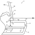
反射面61は、導光体60の後側の傾斜面(例えば、前後方向に対して45°傾斜している)であり、図4に示すように、前方から導光体60に入射した外光N1(以下、前方からの外光には、“N1”と符号を付す。)を下方に効率良く反射させる。なお、図4は、図3に示すHUD装置1の概略断面図の要部を拡大したものであるが、図4では、断面を示すハッチングを省略した(後述の変形例に係る図5(a)(b)も同様)。
The reflecting
対向面62は、導光体60の下面であり、上下方向において光センサ31と対向する面である。また、対向面62は、導光体60が下方に導いた光を外部に出射する出射面として機能する。
The facing
上ケース11のコンバイナ50よりも前方の部分である前方部11Fの一部は、対向面62の一部を下側から覆う覆い部112となっている。上ケース11は、覆い部112が、反射面61で反射し、対向面62から出射され、光センサ31に向かう外光N1の光路を、妨げない部分のみ覆うように構成されている。
A part of the
カバー部材70は、コンバイナ50の側面を覆う部材であり、遮光性の樹脂材料からなる。カバー部材70は、コンバイナ50の側面を保護するため(例えば、衝撃からの保護)、及び、側面(特に、光センサ31の上方に位置する上側面)から外光がコンバイナ50に入射しないようにするために設けられている。無論、カバー部材70は、図2に示すように、導光体60の部分は覆わないように構成されている。
なお、カバー部材70を設けずに、前述の覆い部112によって、コンバイナ50の上側面から入射する光を光センサ31に極力到達させないようにすることもできる。このようにするには、反射面61で反射して、下方に向かう外光の光路は妨げず、コンバイナ50の上側面から入射した外光(つまり、反射面61で反射せずに下方に向かう外光)の光路を塞ぐように、覆い部112を設ければよい。
The
In addition, without providing the
ここで、どのように外光N1が、光センサ31に到達するかを、図4を参照して説明する。
コンバイナ50の前方からの外光N1は、導光体60の前面から入射し、反射面61で反射する。反射した外光N1は、導光体60内部に導かれ下方に向かい、対向面62から出射される。
対向面62から出射された外光N1は、対向面62と向かい合う光センサ31に到達する。そして、光センサ31は、外光N1の明るさを検出し、これに応じた制御部は、前述したように、検出結果に基づいて表示器20の輝度を、適宜、調整する。
Here, how the external light N1 reaches the
External light N1 from the front of the
The external light N1 emitted from the facing
特に、本実施形態では、コンバイナ50の側面にカバー部材70を設けているため、側面(特に、光センサ31の上方部分の上側面)から外光が入射しない。これにより、主に、前方からの外光N1をセンシングすることができる。コンバイナ50の前方は、観察者2が表示画像を視認する際の背景方向であるため、このようにすれば、ほぼ背景の明るさと見なすことができる外光N1の明るさを効果的にセンシングできる。これにより、例えば、昼間のトンネル出口付近で車室内は暗く、表示画像の投影方向(つまり、前方であり背景方向)が明るいといった場合でも、車両がトンネルから出る前に投影方向の明るさにあわせて投影像の輝度を適切な明るさに調整することができる。
In particular, in this embodiment, since the
ここからは、図5(a)(b)を参照して、変形例に係るHUD装置について説明する。なお、上記実施形態と同様な機能を有する各部については、上記実施形態と同じ符号を付し、上記実施形態と重複する説明は省略する。 From here, the HUD device according to the modification will be described with reference to FIGS. In addition, about each part which has the same function as the said embodiment, the code | symbol same as the said embodiment is attached | subjected, and the description which overlaps with the said embodiment is abbreviate | omitted.
(変形例1)
変形例1に係るHUD装置101は、図5(a)に示すように、前方からの外光N1だけでなく、上方からの外光N2(以下、上方からの外光には、“N2”と符号を付す。)も検出するように構成されている。
上方からの外光N2も検出させるためには、カバー部材70を設けないか、又は、カバー部材70のうち、少なくとも、光センサ31の上方に位置する部分(図2に示すB−B線近傍の部分)を切り欠けばよい。無論、この場合には、覆い部112は、コンバイナ50の上側面から入射した外光N2の光路を妨げないように設けられる。
このような構成は、例えば、車内環境により、上方向からの外光N2も検出したほうが、より背景の明るさを反映できる場合などに有効である。
(Modification 1)
As shown in FIG. 5A, the
In order to detect external light N2 from above, the
Such a configuration is more effective when, for example, it is possible to reflect the brightness of the background more by detecting the external light N2 from the upper direction depending on the in-vehicle environment.
(変形例2)
変形例2に係るHUD装置201は、図5(b)に示すように、前方からの外光N1を極力検出させずに、上方からの外光N2を検出できるように構成されている。
この場合も、変形例1と同様に、カバー部材70を設けないか、又は、カバー部材70のうち、少なくとも、光センサ31の上方に位置する部分を切り欠けばよい。そして、覆い部112は、コンバイナ50の上側面から入射した外光N2の光路を妨げないように設けられる。また、このように、上方からの外光N2のみを検出するために、変形例2に係る導光体260には、上記のような反射面61が形成されていない。
このような構成は、例えば、なんらかの要因により、上方からの外光N2が背景の明るさにとって支配的になっている場合などに有効である。
(Modification 2)
As shown in FIG. 5B, the
Also in this case, similarly to the first modification, the
Such a configuration is effective, for example, when the external light N2 from above is dominant for the brightness of the background due to some factor.
以上に説明したHUD装置1(ないしは、101、201)は、表示画像を表す表示光Lを出射する表示器20と、表示器20が出射した表示光Lが入射する凹面50aを有し、入射した表示光Lを集光して観察者2に凹面50a側から前記表示画像を前方の背景と重ねて視認させるコンバイナ50と、コンバイナ50の下方に位置し、到達した光の明るさを検出する光センサ31(光検出部の一例)と、を備え、コンバイナ50は、その下端部に、コンバイナ50と一体である導光体60を有し、導光体60は、上下方向において光センサ31と向かい合う対向面62を有し、入射した外光のうち前方と上方との少なくとも一方からの外光を下方に導き、下方に導いた外光を対向面62から出射し、光センサ31は、対向面62から出射された光の明るさを検出する。
このように、光センサに光を導くため導光体が、コンバイナと一体的に構成されているため、HUD装置1(ないしは、101、201)は、構成が簡潔である。また、部品点数を減らすことも可能であるため、コストの削減を図ることも可能である。
The HUD device 1 (or 101, 201) described above has a
Thus, since the light guide for guiding light to the optical sensor is formed integrally with the combiner, the configuration of the HUD device 1 (or 101, 201) is simple. In addition, since the number of parts can be reduced, the cost can be reduced.
特に、HUD装置1及び変形例1に係るHUD装置101では、導光体60は、前方から入射した外光N1を下方に向けて反射させる反射面61を有し、反射面61で反射した外光を対向面62から出射する。このため、前述したように、背景方向の明るさを効果的に検出可能である。
In particular, in the
なお、本発明は上記実施形態、その変形例(変形例1、2)、及び図面によって限定されるものではない。これらに変更(構成要素の削除も含む)を加えることができるのはもちろんである。
In addition, this invention is not limited by the said embodiment, its modification (
以上の説明では、導光体60が有する反射面61の角度が、例えば45°である例を示したがこれに限られない。反射面61の傾斜角を45°からずらすことで、光センサ31に到達する外光N1の量を調整する(抑制する)ことも可能である。
In the above description, an example in which the angle of the
以上の説明では、表示器20からの表示光Lを、反射部40で反射させ、コンバイナ50に到達させる例を示したが、これに限られない。表示器が表示光Lを直接コンバイナに向けて出射するようにHUD装置を構成してもよい。この場合、表示器とコンバイナとは略対向するように設けられ、反射部40は、不要である。
In the above description, the example in which the display light L from the
以上の説明では、HUD装置1(以下、HUD装置101、201も同様)を設置する乗り物の一例を車両としたが、これに限られない。HUD装置1を船舶、航空機等のその他の乗り物の運転席付近に設置することもできる。さらには、乗り物の運転席付近に設置するものに限らず、室内に設置する卓上インテリア等に適用することも可能である。
In the above description, an example of a vehicle on which the HUD device 1 (hereinafter, the same applies to the
また、以上では、HUD装置1を据え置き型のものとして説明したが、HUD装置1は、例えば、車両のダッシュボードと一体的に構成されるものであってもよい。
In the above description, the
以上の説明では、本発明の理解を容易にするために、重要でない公知の技術的事項の説明を適宜省略した。 In the above description, in order to facilitate the understanding of the present invention, the description of known unimportant technical matters is appropriately omitted.
1 …HUD装置
2 …観察者
10 …ケース体
11 …上ケース
11F…前方部
110…第1の開口部
111…第2の開口部
112…覆い部
12 …下ケース
121…凹部
13 …中ケース
130…出射口
20 …表示器
30 …回路基板
31 …光センサ
40 …反射部
50 …コンバイナ
50a…凹面
60 …導光体
61 …反射面
62 …対向面
70 …カバー部材
DESCRIPTION OF
Claims (4)
前記表示器が出射した表示光が入射する凹面を有し、入射した表示光を集光して観察者に前記凹面側から前記表示画像を前方の背景と重ねて視認させるコンバイナと、
前記コンバイナの下方に位置し、到達した光の明るさを検出する光検出部と、を備え、
前記コンバイナは、その下端部に、前記コンバイナと一体である導光体を有し、
前記導光体は、上下方向において前記光検出部と向かい合う対向面を有し、前方から入射した外光を下方に向けて反射させる反射面を有し、前記反射面で反射した外光を前記対向面から出射し、
前記光検出部は、前記対向面から出射された光の明るさを検出する、
ことを特徴とするヘッドアップディスプレイ装置。 A display that emits display light representing a display image;
A combiner having a concave surface on which the display light emitted from the display is incident, condensing the incident display light and allowing an observer to visually recognize the display image from the concave surface side, and
A light detection unit that is located below the combiner and detects the brightness of the reached light;
The combiner has a light guide that is integral with the combiner at its lower end,
The light guide has a facing surface facing the light detection unit in the vertical direction, has a reflection surface that reflects external light incident from the front downward, and the external light reflected by the reflection surface is Exits from the opposite surface,
The light detection unit detects the brightness of the light emitted from the facing surface;
A head-up display device.
ことを特徴とする請求項1に記載のヘッドアップディスプレイ装置。 Covering a part of the facing surface from the lower side, including a cover portion that passes through the light guide from above the combiner and prevents an optical path of light traveling downward.
The head-up display device according to claim 1 .
ことを特徴とする請求項1に記載のヘッドアップディスプレイ装置。 A light-shielding cover member that covers the upper side surface of the combiner is provided, and is configured so that external light does not enter from the upper side surface.
The head-up display device according to claim 1 .
ことを特徴とする請求項1乃至3のいずれか1項に記載のヘッドアップディスプレイ装置。
Adjusting means for adjusting the display brightness of the display based on the brightness of the light detected by the light detection unit;
Head-up display device according to any one of claims 1 to 3, characterized in that.
Priority Applications (7)
| Application Number | Priority Date | Filing Date | Title |
|---|---|---|---|
| JP2012078120A JP5998578B2 (en) | 2012-03-29 | 2012-03-29 | Head-up display device |
| IN8234DEN2014 IN2014DN08234A (en) | 2012-03-29 | 2013-03-07 | |
| KR1020147027744A KR20140141629A (en) | 2012-03-29 | 2013-03-07 | Heads-up display device |
| US14/388,737 US9242604B2 (en) | 2012-03-29 | 2013-03-07 | Head-up display device |
| EP13768908.9A EP2833194B1 (en) | 2012-03-29 | 2013-03-07 | Heads-up display device |
| CN201380016253.1A CN104204903B (en) | 2012-03-29 | 2013-03-07 | Head-up display |
| PCT/JP2013/056261 WO2013146160A1 (en) | 2012-03-29 | 2013-03-07 | Heads-up display device |
Applications Claiming Priority (1)
| Application Number | Priority Date | Filing Date | Title |
|---|---|---|---|
| JP2012078120A JP5998578B2 (en) | 2012-03-29 | 2012-03-29 | Head-up display device |
Publications (2)
| Publication Number | Publication Date |
|---|---|
| JP2013205817A JP2013205817A (en) | 2013-10-07 |
| JP5998578B2 true JP5998578B2 (en) | 2016-09-28 |
Family
ID=49259428
Family Applications (1)
| Application Number | Title | Priority Date | Filing Date |
|---|---|---|---|
| JP2012078120A Expired - Fee Related JP5998578B2 (en) | 2012-03-29 | 2012-03-29 | Head-up display device |
Country Status (7)
| Country | Link |
|---|---|
| US (1) | US9242604B2 (en) |
| EP (1) | EP2833194B1 (en) |
| JP (1) | JP5998578B2 (en) |
| KR (1) | KR20140141629A (en) |
| CN (1) | CN104204903B (en) |
| IN (1) | IN2014DN08234A (en) |
| WO (1) | WO2013146160A1 (en) |
Families Citing this family (33)
| Publication number | Priority date | Publication date | Assignee | Title |
|---|---|---|---|---|
| JP6349632B2 (en) * | 2013-06-24 | 2018-07-04 | 日本精機株式会社 | Head-up display device |
| JP2015127170A (en) * | 2013-12-27 | 2015-07-09 | パイオニア株式会社 | Head-up display, control method, program, and memory medium |
| WO2015098075A1 (en) * | 2013-12-27 | 2015-07-02 | パナソニックIpマネジメント株式会社 | Display equipment and display unit |
| CN104914574B (en) * | 2014-03-11 | 2018-12-14 | 鸿富锦精密工业(深圳)有限公司 | Head-up display device |
| CN103885183B (en) * | 2014-03-12 | 2017-01-04 | 惠州市华阳多媒体电子有限公司 | Callable vehicle-mounted head-up display and vehicle |
| EP2930048A1 (en) * | 2014-04-10 | 2015-10-14 | Johnson Controls Automotive Electronics SAS | Head up display projecting visual information onto a screen |
| JP2015214246A (en) * | 2014-05-09 | 2015-12-03 | カルソニックカンセイ株式会社 | Vehicle display device |
| DE112015002757B4 (en) | 2014-06-12 | 2021-07-29 | Yazaki Corporation | Visor body and vehicle display device |
| JP6284153B2 (en) * | 2014-06-12 | 2018-02-28 | 矢崎総業株式会社 | External light introducing member and vehicle display device |
| EP3165959B1 (en) * | 2014-07-01 | 2018-11-07 | Ricoh Company, Ltd. | Vehicular display device with improved brightness adjustment regarding to the background illuminance |
| DE102014019160B4 (en) * | 2014-12-19 | 2021-04-29 | Audi Ag | Method for reducing a reflection when operating a head-up display of a motor vehicle, a head-up display, and a motor vehicle with a head-up display |
| TWI572503B (en) * | 2015-02-24 | 2017-03-01 | 晶典有限公司 | Head up display system |
| TWI554785B (en) * | 2015-03-19 | 2016-10-21 | 尚立光電股份有限公司 | Displayer with asymmetry prism and head up displayer thereof |
| DE102016209526A1 (en) * | 2015-06-12 | 2016-12-15 | Ford Global Technologies, Llc | A projection device and method for projecting a virtual image into a field of view of a driver of a vehicle |
| JP6595250B2 (en) * | 2015-08-06 | 2019-10-23 | 株式会社ポラテクノ | Head-up display device |
| JP6661955B2 (en) * | 2015-10-08 | 2020-03-11 | 株式会社リコー | Display device |
| KR102363992B1 (en) * | 2015-11-24 | 2022-02-18 | 현대모비스 주식회사 | Head up display device for vehicle |
| US20170148216A1 (en) * | 2015-11-25 | 2017-05-25 | Continental Automotive Systems, Inc. | Display system adjustable based on background |
| CN108463767B (en) * | 2016-01-12 | 2021-10-01 | 奇跃公司 | Beam angle sensor in virtual/augmented reality systems |
| WO2017147158A1 (en) * | 2016-02-22 | 2017-08-31 | Navdy, Inc. | Head-up display device and method for constructing the same |
| FR3050541B1 (en) * | 2016-04-26 | 2019-07-12 | Valeo Comfort And Driving Assistance | DISPLAY |
| FR3050542B1 (en) * | 2016-04-26 | 2019-07-12 | Valeo Comfort And Driving Assistance | DISPLAY COMPRISING A LIGHT SENSOR |
| JP6559105B2 (en) * | 2016-08-31 | 2019-08-14 | 富士フイルム株式会社 | Head-up display device |
| CN106547094A (en) * | 2016-11-25 | 2017-03-29 | 刘涛 | The equipment that new line shows is realized using shield glass |
| CN106772967A (en) * | 2016-12-06 | 2017-05-31 | 中国航空工业集团公司洛阳电光设备研究所 | A kind of Clairvoyant type speech display optical system |
| CN108237975B (en) * | 2016-12-23 | 2021-06-11 | 大众汽车(中国)投资有限公司 | Method and device for illumination adjustment |
| KR20180093583A (en) * | 2017-02-14 | 2018-08-22 | 현대모비스 주식회사 | Head up display apparatus having multi display field capable of individual control and display control method for head up dispaly apparatus |
| US20190033582A1 (en) * | 2017-07-31 | 2019-01-31 | Benoit CHAUVEAU | Embedded sensor in a heads-up display (hud) panel |
| USD888633S1 (en) * | 2017-10-17 | 2020-06-30 | Lg Electronics Inc. | Head-up display for car |
| USD900689S1 (en) * | 2017-10-17 | 2020-11-03 | Lg Electronics Inc. | Head-up display for car |
| JP6995646B2 (en) * | 2018-01-26 | 2022-01-14 | 本田技研工業株式会社 | Display device |
| FR3084476B1 (en) * | 2018-07-30 | 2022-12-30 | Valeo Comfort & Driving Assistance | LIGHT SENSOR DISPLAY |
| CN109521564A (en) * | 2018-11-20 | 2019-03-26 | 惠州市华阳多媒体电子有限公司 | A kind of vehicle-mounted multi-screen holographic projection system |
Family Cites Families (9)
| Publication number | Priority date | Publication date | Assignee | Title |
|---|---|---|---|---|
| CA954347A (en) * | 1970-06-22 | 1974-09-10 | Robert K. Kirschner | Head-up display |
| JPH0425816A (en) * | 1990-05-22 | 1992-01-29 | Nissan Motor Co Ltd | Foreground brightness detection device |
| JP3241824B2 (en) * | 1992-10-30 | 2001-12-25 | カルソニックカンセイ株式会社 | Head-up display device with automatic dimming function for vehicles |
| JPH0943531A (en) * | 1995-07-31 | 1997-02-14 | Fujitsu Ltd | Display device for vehicle |
| JPH0954276A (en) * | 1995-08-11 | 1997-02-25 | Denso Corp | Head-up display |
| JP4089075B2 (en) * | 1999-03-30 | 2008-05-21 | 株式会社島津製作所 | Head-up display system |
| US7561966B2 (en) * | 2003-12-17 | 2009-07-14 | Denso Corporation | Vehicle information display system |
| JP5012640B2 (en) * | 2008-04-25 | 2012-08-29 | 株式会社島津製作所 | Display device |
| DE102009053825A1 (en) * | 2009-11-18 | 2011-05-19 | Trw Automotive Electronics & Components Gmbh | Optical sensor device for detecting ambient light |
-
2012
- 2012-03-29 JP JP2012078120A patent/JP5998578B2/en not_active Expired - Fee Related
-
2013
- 2013-03-07 EP EP13768908.9A patent/EP2833194B1/en not_active Not-in-force
- 2013-03-07 KR KR1020147027744A patent/KR20140141629A/en not_active Application Discontinuation
- 2013-03-07 US US14/388,737 patent/US9242604B2/en not_active Expired - Fee Related
- 2013-03-07 CN CN201380016253.1A patent/CN104204903B/en not_active Expired - Fee Related
- 2013-03-07 IN IN8234DEN2014 patent/IN2014DN08234A/en unknown
- 2013-03-07 WO PCT/JP2013/056261 patent/WO2013146160A1/en active Application Filing
Also Published As
| Publication number | Publication date |
|---|---|
| CN104204903B (en) | 2016-08-31 |
| KR20140141629A (en) | 2014-12-10 |
| EP2833194B1 (en) | 2018-06-06 |
| US20150035725A1 (en) | 2015-02-05 |
| WO2013146160A1 (en) | 2013-10-03 |
| CN104204903A (en) | 2014-12-10 |
| JP2013205817A (en) | 2013-10-07 |
| EP2833194A1 (en) | 2015-02-04 |
| EP2833194A4 (en) | 2017-04-12 |
| IN2014DN08234A (en) | 2015-05-15 |
| US9242604B2 (en) | 2016-01-26 |
Similar Documents
| Publication | Publication Date | Title |
|---|---|---|
| JP5998578B2 (en) | Head-up display device | |
| JP6349632B2 (en) | Head-up display device | |
| KR101823180B1 (en) | Vehicular heads-up display device | |
| JP5919724B2 (en) | Head-up display device for vehicle | |
| JP2006106254A (en) | Head-up display for vehicle | |
| US20150123878A1 (en) | Information display device | |
| JP5888003B2 (en) | Head-up display device | |
| JP7008267B2 (en) | Head-up display device | |
| US10746984B2 (en) | Projection display device with cover | |
| US10656419B2 (en) | Head-up display apparatus integrated with cluster | |
| US20150015963A1 (en) | Display unit | |
| JP2012063524A (en) | Vehicular head-up display device | |
| JP2009067251A (en) | Information display device | |
| JP6287017B2 (en) | Head-up display device | |
| US11919391B2 (en) | On-vehicle display apparatus | |
| JP6435611B2 (en) | Vehicle warning device and vehicle warning unit | |
| JP2005326723A (en) | On-vehicle head-up display | |
| JP2017149354A (en) | Head-up display device | |
| JP2004249752A (en) | Display device for vehicle | |
| JP2018030522A (en) | Head-up display device | |
| KR20230089459A (en) | Head up display apparatus | |
| JP2024053592A (en) | Head-up display device | |
| JP2015118165A (en) | Instrument for vehicle | |
| JP2023152513A (en) | Head-up display | |
| JP2021128258A (en) | Display device |
Legal Events
| Date | Code | Title | Description |
|---|---|---|---|
| A621 | Written request for application examination |
Free format text: JAPANESE INTERMEDIATE CODE: A621 Effective date: 20150116 |
|
| A131 | Notification of reasons for refusal |
Free format text: JAPANESE INTERMEDIATE CODE: A131 Effective date: 20151222 |
|
| A521 | Request for written amendment filed |
Free format text: JAPANESE INTERMEDIATE CODE: A523 Effective date: 20160208 |
|
| TRDD | Decision of grant or rejection written | ||
| A01 | Written decision to grant a patent or to grant a registration (utility model) |
Free format text: JAPANESE INTERMEDIATE CODE: A01 Effective date: 20160802 |
|
| A61 | First payment of annual fees (during grant procedure) |
Free format text: JAPANESE INTERMEDIATE CODE: A61 Effective date: 20160815 |
|
| R150 | Certificate of patent or registration of utility model |
Ref document number: 5998578 Country of ref document: JP Free format text: JAPANESE INTERMEDIATE CODE: R150 |
|
| LAPS | Cancellation because of no payment of annual fees |