JP5995878B2 - Improved exercise equipment - Google Patents
Improved exercise equipment Download PDFInfo
- Publication number
- JP5995878B2 JP5995878B2 JP2013557172A JP2013557172A JP5995878B2 JP 5995878 B2 JP5995878 B2 JP 5995878B2 JP 2013557172 A JP2013557172 A JP 2013557172A JP 2013557172 A JP2013557172 A JP 2013557172A JP 5995878 B2 JP5995878 B2 JP 5995878B2
- Authority
- JP
- Japan
- Prior art keywords
- movable
- user
- movable section
- cam
- resistance device
- Prior art date
- Legal status (The legal status is an assumption and is not a legal conclusion. Google has not performed a legal analysis and makes no representation as to the accuracy of the status listed.)
- Expired - Fee Related
Links
Images


Classifications
-
- A—HUMAN NECESSITIES
- A63—SPORTS; GAMES; AMUSEMENTS
- A63B—APPARATUS FOR PHYSICAL TRAINING, GYMNASTICS, SWIMMING, CLIMBING, OR FENCING; BALL GAMES; TRAINING EQUIPMENT
- A63B23/00—Exercising apparatus specially adapted for particular parts of the body
- A63B23/035—Exercising apparatus specially adapted for particular parts of the body for limbs, i.e. upper or lower limbs, e.g. simultaneously
- A63B23/12—Exercising apparatus specially adapted for particular parts of the body for limbs, i.e. upper or lower limbs, e.g. simultaneously for upper limbs or related muscles, e.g. chest, upper back or shoulder muscles
-
- A—HUMAN NECESSITIES
- A63—SPORTS; GAMES; AMUSEMENTS
- A63B—APPARATUS FOR PHYSICAL TRAINING, GYMNASTICS, SWIMMING, CLIMBING, OR FENCING; BALL GAMES; TRAINING EQUIPMENT
- A63B21/00—Exercising apparatus for developing or strengthening the muscles or joints of the body by working against a counterforce, with or without measuring devices
- A63B21/40—Interfaces with the user related to strength training; Details thereof
- A63B21/4027—Specific exercise interfaces
- A63B21/4033—Handles, pedals, bars or platforms
- A63B21/4035—Handles, pedals, bars or platforms for operation by hand
-
- A—HUMAN NECESSITIES
- A63—SPORTS; GAMES; AMUSEMENTS
- A63B—APPARATUS FOR PHYSICAL TRAINING, GYMNASTICS, SWIMMING, CLIMBING, OR FENCING; BALL GAMES; TRAINING EQUIPMENT
- A63B21/00—Exercising apparatus for developing or strengthening the muscles or joints of the body by working against a counterforce, with or without measuring devices
- A63B21/02—Exercising apparatus for developing or strengthening the muscles or joints of the body by working against a counterforce, with or without measuring devices using resilient force-resisters
- A63B21/055—Exercising apparatus for developing or strengthening the muscles or joints of the body by working against a counterforce, with or without measuring devices using resilient force-resisters extension element type
- A63B21/0552—Elastic ropes or bands
-
- A—HUMAN NECESSITIES
- A63—SPORTS; GAMES; AMUSEMENTS
- A63B—APPARATUS FOR PHYSICAL TRAINING, GYMNASTICS, SWIMMING, CLIMBING, OR FENCING; BALL GAMES; TRAINING EQUIPMENT
- A63B21/00—Exercising apparatus for developing or strengthening the muscles or joints of the body by working against a counterforce, with or without measuring devices
- A63B21/06—User-manipulated weights
- A63B21/062—User-manipulated weights including guide for vertical or non-vertical weights or array of weights to move against gravity forces
- A63B21/0626—User-manipulated weights including guide for vertical or non-vertical weights or array of weights to move against gravity forces with substantially vertical guiding means
- A63B21/0628—User-manipulated weights including guide for vertical or non-vertical weights or array of weights to move against gravity forces with substantially vertical guiding means for vertical array of weights
-
- A—HUMAN NECESSITIES
- A63—SPORTS; GAMES; AMUSEMENTS
- A63B—APPARATUS FOR PHYSICAL TRAINING, GYMNASTICS, SWIMMING, CLIMBING, OR FENCING; BALL GAMES; TRAINING EQUIPMENT
- A63B21/00—Exercising apparatus for developing or strengthening the muscles or joints of the body by working against a counterforce, with or without measuring devices
- A63B21/15—Arrangements for force transmissions
- A63B21/151—Using flexible elements for reciprocating movements, e.g. ropes or chains
- A63B21/154—Using flexible elements for reciprocating movements, e.g. ropes or chains using special pulley-assemblies
- A63B21/155—Cam-shaped pulleys or other non-uniform pulleys, e.g. conical
-
- A—HUMAN NECESSITIES
- A63—SPORTS; GAMES; AMUSEMENTS
- A63B—APPARATUS FOR PHYSICAL TRAINING, GYMNASTICS, SWIMMING, CLIMBING, OR FENCING; BALL GAMES; TRAINING EQUIPMENT
- A63B21/00—Exercising apparatus for developing or strengthening the muscles or joints of the body by working against a counterforce, with or without measuring devices
- A63B21/15—Arrangements for force transmissions
- A63B21/151—Using flexible elements for reciprocating movements, e.g. ropes or chains
- A63B21/154—Using flexible elements for reciprocating movements, e.g. ropes or chains using special pulley-assemblies
- A63B21/156—Using flexible elements for reciprocating movements, e.g. ropes or chains using special pulley-assemblies the position of the pulleys being variable, e.g. for different exercises
-
- A—HUMAN NECESSITIES
- A63—SPORTS; GAMES; AMUSEMENTS
- A63B—APPARATUS FOR PHYSICAL TRAINING, GYMNASTICS, SWIMMING, CLIMBING, OR FENCING; BALL GAMES; TRAINING EQUIPMENT
- A63B21/00—Exercising apparatus for developing or strengthening the muscles or joints of the body by working against a counterforce, with or without measuring devices
- A63B21/40—Interfaces with the user related to strength training; Details thereof
- A63B21/4041—Interfaces with the user related to strength training; Details thereof characterised by the movements of the interface
- A63B21/4047—Pivoting movement
-
- A—HUMAN NECESSITIES
- A63—SPORTS; GAMES; AMUSEMENTS
- A63B—APPARATUS FOR PHYSICAL TRAINING, GYMNASTICS, SWIMMING, CLIMBING, OR FENCING; BALL GAMES; TRAINING EQUIPMENT
- A63B21/00—Exercising apparatus for developing or strengthening the muscles or joints of the body by working against a counterforce, with or without measuring devices
- A63B21/40—Interfaces with the user related to strength training; Details thereof
- A63B21/4041—Interfaces with the user related to strength training; Details thereof characterised by the movements of the interface
- A63B21/4049—Rotational movement
-
- A—HUMAN NECESSITIES
- A63—SPORTS; GAMES; AMUSEMENTS
- A63B—APPARATUS FOR PHYSICAL TRAINING, GYMNASTICS, SWIMMING, CLIMBING, OR FENCING; BALL GAMES; TRAINING EQUIPMENT
- A63B23/00—Exercising apparatus specially adapted for particular parts of the body
- A63B23/025—Exercising apparatus specially adapted for particular parts of the body for the head or the neck
-
- A—HUMAN NECESSITIES
- A63—SPORTS; GAMES; AMUSEMENTS
- A63B—APPARATUS FOR PHYSICAL TRAINING, GYMNASTICS, SWIMMING, CLIMBING, OR FENCING; BALL GAMES; TRAINING EQUIPMENT
- A63B23/00—Exercising apparatus specially adapted for particular parts of the body
- A63B23/035—Exercising apparatus specially adapted for particular parts of the body for limbs, i.e. upper or lower limbs, e.g. simultaneously
- A63B23/03516—For both arms together or both legs together; Aspects related to the co-ordination between right and left side limbs of a user
- A63B23/03525—Supports for both feet or both hands performing simultaneously the same movement, e.g. single pedal or single handle
-
- A—HUMAN NECESSITIES
- A63—SPORTS; GAMES; AMUSEMENTS
- A63B—APPARATUS FOR PHYSICAL TRAINING, GYMNASTICS, SWIMMING, CLIMBING, OR FENCING; BALL GAMES; TRAINING EQUIPMENT
- A63B23/00—Exercising apparatus specially adapted for particular parts of the body
- A63B23/035—Exercising apparatus specially adapted for particular parts of the body for limbs, i.e. upper or lower limbs, e.g. simultaneously
- A63B23/03516—For both arms together or both legs together; Aspects related to the co-ordination between right and left side limbs of a user
- A63B23/03533—With separate means driven by each limb, i.e. performing different movements
-
- A—HUMAN NECESSITIES
- A63—SPORTS; GAMES; AMUSEMENTS
- A63B—APPARATUS FOR PHYSICAL TRAINING, GYMNASTICS, SWIMMING, CLIMBING, OR FENCING; BALL GAMES; TRAINING EQUIPMENT
- A63B23/00—Exercising apparatus specially adapted for particular parts of the body
- A63B23/035—Exercising apparatus specially adapted for particular parts of the body for limbs, i.e. upper or lower limbs, e.g. simultaneously
- A63B23/04—Exercising apparatus specially adapted for particular parts of the body for limbs, i.e. upper or lower limbs, e.g. simultaneously for lower limbs
-
- A—HUMAN NECESSITIES
- A63—SPORTS; GAMES; AMUSEMENTS
- A63B—APPARATUS FOR PHYSICAL TRAINING, GYMNASTICS, SWIMMING, CLIMBING, OR FENCING; BALL GAMES; TRAINING EQUIPMENT
- A63B23/00—Exercising apparatus specially adapted for particular parts of the body
- A63B23/035—Exercising apparatus specially adapted for particular parts of the body for limbs, i.e. upper or lower limbs, e.g. simultaneously
- A63B23/12—Exercising apparatus specially adapted for particular parts of the body for limbs, i.e. upper or lower limbs, e.g. simultaneously for upper limbs or related muscles, e.g. chest, upper back or shoulder muscles
- A63B23/1209—Involving a bending of elbow and shoulder joints simultaneously
-
- A—HUMAN NECESSITIES
- A63—SPORTS; GAMES; AMUSEMENTS
- A63B—APPARATUS FOR PHYSICAL TRAINING, GYMNASTICS, SWIMMING, CLIMBING, OR FENCING; BALL GAMES; TRAINING EQUIPMENT
- A63B23/00—Exercising apparatus specially adapted for particular parts of the body
- A63B23/035—Exercising apparatus specially adapted for particular parts of the body for limbs, i.e. upper or lower limbs, e.g. simultaneously
- A63B23/12—Exercising apparatus specially adapted for particular parts of the body for limbs, i.e. upper or lower limbs, e.g. simultaneously for upper limbs or related muscles, e.g. chest, upper back or shoulder muscles
- A63B23/1245—Primarily by articulating the shoulder joint
- A63B23/1263—Rotation about an axis passing through both shoulders, e.g. cross-country skiing-type arm movements
-
- A—HUMAN NECESSITIES
- A63—SPORTS; GAMES; AMUSEMENTS
- A63B—APPARATUS FOR PHYSICAL TRAINING, GYMNASTICS, SWIMMING, CLIMBING, OR FENCING; BALL GAMES; TRAINING EQUIPMENT
- A63B71/00—Games or sports accessories not covered in groups A63B1/00 - A63B69/00
- A63B71/0054—Features for injury prevention on an apparatus, e.g. shock absorbers
- A63B2071/0072—Limiting the applied force, torque, movement or speed
-
- A—HUMAN NECESSITIES
- A63—SPORTS; GAMES; AMUSEMENTS
- A63B—APPARATUS FOR PHYSICAL TRAINING, GYMNASTICS, SWIMMING, CLIMBING, OR FENCING; BALL GAMES; TRAINING EQUIPMENT
- A63B71/00—Games or sports accessories not covered in groups A63B1/00 - A63B69/00
- A63B71/0054—Features for injury prevention on an apparatus, e.g. shock absorbers
- A63B2071/009—Protective housings covering the working parts of the apparatus
-
- A—HUMAN NECESSITIES
- A63—SPORTS; GAMES; AMUSEMENTS
- A63B—APPARATUS FOR PHYSICAL TRAINING, GYMNASTICS, SWIMMING, CLIMBING, OR FENCING; BALL GAMES; TRAINING EQUIPMENT
- A63B21/00—Exercising apparatus for developing or strengthening the muscles or joints of the body by working against a counterforce, with or without measuring devices
- A63B21/40—Interfaces with the user related to strength training; Details thereof
- A63B21/4027—Specific exercise interfaces
- A63B21/4033—Handles, pedals, bars or platforms
-
- A—HUMAN NECESSITIES
- A63—SPORTS; GAMES; AMUSEMENTS
- A63B—APPARATUS FOR PHYSICAL TRAINING, GYMNASTICS, SWIMMING, CLIMBING, OR FENCING; BALL GAMES; TRAINING EQUIPMENT
- A63B21/00—Exercising apparatus for developing or strengthening the muscles or joints of the body by working against a counterforce, with or without measuring devices
- A63B21/40—Interfaces with the user related to strength training; Details thereof
- A63B21/4027—Specific exercise interfaces
- A63B21/4039—Specific exercise interfaces contoured to fit to specific body parts, e.g. back, knee or neck support
-
- A—HUMAN NECESSITIES
- A63—SPORTS; GAMES; AMUSEMENTS
- A63B—APPARATUS FOR PHYSICAL TRAINING, GYMNASTICS, SWIMMING, CLIMBING, OR FENCING; BALL GAMES; TRAINING EQUIPMENT
- A63B2208/00—Characteristics or parameters related to the user or player
- A63B2208/02—Characteristics or parameters related to the user or player posture
- A63B2208/0228—Sitting on the buttocks
- A63B2208/0233—Sitting on the buttocks in 90/90 position, like on a chair
-
- A—HUMAN NECESSITIES
- A63—SPORTS; GAMES; AMUSEMENTS
- A63B—APPARATUS FOR PHYSICAL TRAINING, GYMNASTICS, SWIMMING, CLIMBING, OR FENCING; BALL GAMES; TRAINING EQUIPMENT
- A63B2210/00—Space saving
- A63B2210/50—Size reducing arrangements for stowing or transport
-
- A—HUMAN NECESSITIES
- A63—SPORTS; GAMES; AMUSEMENTS
- A63B—APPARATUS FOR PHYSICAL TRAINING, GYMNASTICS, SWIMMING, CLIMBING, OR FENCING; BALL GAMES; TRAINING EQUIPMENT
- A63B2225/00—Miscellaneous features of sport apparatus, devices or equipment
- A63B2225/09—Adjustable dimensions
-
- A—HUMAN NECESSITIES
- A63—SPORTS; GAMES; AMUSEMENTS
- A63B—APPARATUS FOR PHYSICAL TRAINING, GYMNASTICS, SWIMMING, CLIMBING, OR FENCING; BALL GAMES; TRAINING EQUIPMENT
- A63B2225/00—Miscellaneous features of sport apparatus, devices or equipment
- A63B2225/09—Adjustable dimensions
- A63B2225/093—Height
-
- A—HUMAN NECESSITIES
- A63—SPORTS; GAMES; AMUSEMENTS
- A63B—APPARATUS FOR PHYSICAL TRAINING, GYMNASTICS, SWIMMING, CLIMBING, OR FENCING; BALL GAMES; TRAINING EQUIPMENT
- A63B23/00—Exercising apparatus specially adapted for particular parts of the body
- A63B23/02—Exercising apparatus specially adapted for particular parts of the body for the abdomen, the spinal column or the torso muscles related to shoulders (e.g. chest muscles)
- A63B23/0233—Muscles of the back, e.g. by an extension of the body against a resistance, reverse crunch
-
- A—HUMAN NECESSITIES
- A63—SPORTS; GAMES; AMUSEMENTS
- A63B—APPARATUS FOR PHYSICAL TRAINING, GYMNASTICS, SWIMMING, CLIMBING, OR FENCING; BALL GAMES; TRAINING EQUIPMENT
- A63B23/00—Exercising apparatus specially adapted for particular parts of the body
- A63B23/035—Exercising apparatus specially adapted for particular parts of the body for limbs, i.e. upper or lower limbs, e.g. simultaneously
- A63B23/0355—A single apparatus used for either upper or lower limbs, i.e. with a set of support elements driven either by the upper or the lower limb or limbs
-
- A—HUMAN NECESSITIES
- A63—SPORTS; GAMES; AMUSEMENTS
- A63B—APPARATUS FOR PHYSICAL TRAINING, GYMNASTICS, SWIMMING, CLIMBING, OR FENCING; BALL GAMES; TRAINING EQUIPMENT
- A63B23/00—Exercising apparatus specially adapted for particular parts of the body
- A63B23/035—Exercising apparatus specially adapted for particular parts of the body for limbs, i.e. upper or lower limbs, e.g. simultaneously
- A63B23/04—Exercising apparatus specially adapted for particular parts of the body for limbs, i.e. upper or lower limbs, e.g. simultaneously for lower limbs
- A63B23/0482—Exercising apparatus specially adapted for particular parts of the body for limbs, i.e. upper or lower limbs, e.g. simultaneously for lower limbs primarily by articulating the hip joints
Description
本発明は、改良型エクササイズ装置に関する。 The present invention relates to an improved exercise device.
一部の既存のエクササイズ装置に関する問題は、エクササイズの可動域の全体にわたって関節の方向および/または関節にかかる負荷がほとんど制御されないことである。 A problem with some existing exercise devices is that the direction of the joint and / or the load on the joint is hardly controlled throughout the range of motion of the exercise.
カムをベースとしない固定ウェイトマシン、フリーウェイト、およびケーブルマシンは、例えば、複数の関節をトレーニングすることができるが、重力の方向、ケーブルの方向、および/または機構の動作によって規定される特定の方向に固定された負荷を加えるものであり、負荷の方向が、使用者の動作に適合されない。したがって、使用者が、例えば自分の手足を動かすとき、負荷は最初、動作に対して垂直に作用するが、可動域の間に負荷は、垂直からずれた角度で作用する可能性がある。 Non-cam-based fixed weight machines, free weights, and cable machines, for example, can train multiple joints, but are specified by the direction of gravity, the direction of the cable, and / or the behavior of the mechanism The load is fixed in the direction, and the direction of the load is not adapted to the operation of the user. Thus, when a user moves his / her limb, for example, the load initially acts perpendicular to the motion, but during the range of motion, the load may act at an angle that is off-vertical.
結果として、関節または各関節に十分に負荷がかからず、この結果、エクササイズの効率が低下する。さらに、ケーブルマシンおよびフリーウェイトでは、使用者の関節が支持されていないため、使用者は、とりわけ疲労している場合に、関節および/または筋肉に損傷を与える可能性がある不自然な姿勢でエクササイズする可能性がある。 As a result, the joint or each joint is not fully loaded, resulting in a decrease in exercise efficiency. In addition, with cable machines and free weights, the user's joints are not supported, so the user is in an unnatural posture that can damage the joints and / or muscles, especially when they are tired. There is a possibility of exercising.
カムベースのマシン(Nautilusによって製造されたものなど)は、カムによって関節に加えられる回転負荷を利用して可動域の全体にわたって関節に負荷を均等に加える。しばらくの間は、このようなマシンを利用することができる。このようなマシンの欠点は、該マシンが、1つの関節を一方向にエクササイズすることに制限されており、単一の関節のみがエクササイズされ、多関節エクササイズが不可能なことである。 Cam-based machines (such as those manufactured by Natilus) apply the load to the joint evenly throughout the range of motion using the rotational load applied to the joint by the cam. For a while, you can use such a machine. The disadvantage of such a machine is that it is limited to exercising one joint in one direction, only a single joint is exercised and multi-joint exercise is not possible.
William Kurt Edekerの名義の米国特許第7645216号明細書は、多関節エクササイズを可能とするリンクカム構成を備える枢動部分を備えるエクササイズマシンについて開示している。これらのマシンの1つの欠点は、単一の運動面および/または動作経路でしか動作しないことである。さらなる欠点は、カムが互いに連動されているため、関節をエクササイズするために枢動する部分は、一方の部分の動作が、もう一方の動作をもたらすか、または、もう一方の動作に従属するように、従属的に連動されていることである。従属的に連動されていることによって、各関節に関するマシンの利点は制限されている。なぜなら、より大きな筋肉群が、より小さな筋肉群を補償してしまい、この結果、エクササイズの効果が減少する場合があるからである。さらに、このようなトレーニングでは、関節のうちの少なくとも1つの全可動域にわたっては負荷が加えられない。 U.S. Pat. No. 7,645,216 in the name of William Kurt Edeker discloses an exercise machine with a pivoting part with a link cam configuration that allows multi-joint exercise. One disadvantage of these machines is that they operate only on a single motion surface and / or motion path. A further disadvantage is that since the cams are interlocked with each other, the part that pivots to exercise the joint is such that the action of one part results in or is subordinate to the action of the other. It is that they are linked in a dependent manner. By being interlocked in a dependent manner, the machine's advantages with respect to each joint are limited. This is because the larger muscle group compensates for the smaller muscle group, and as a result, the exercise effect may be reduced. Furthermore, in such training, no load is applied over the entire range of motion of at least one of the joints.
国際公開第2008/009949号パンフレットは、使用者の頸椎を強化するための筋肉調整装置について開示している。しかしながら、その動作は、背中および首のみのエクササイズを可能とするように制限されている。 WO 2008/009949 discloses a muscle conditioning device for strengthening the user's cervical spine. However, its movement is limited to allow back and neck only exercises.
したがって、本発明は、フレームワークと、少なくとも1つの抵抗力を生み出す手段と、可動セクションとを備える筋肉抵抗装置であって、可動セクションが、その長手方向に沿って少なくとも1つの位置において抵抗力またはそれぞれの抵抗力とリンクされており、可動セクションの第1の部分は、該第1の部分が一時的に変位することを可能とする第1の連結部によって、フレームワークに取り付けられており、可動セクションの第2の部分は、該第2の部分が一時的に変位することを可能とする第2の連結部によって、可動セクションの第1の部分と連結されており、可動セクションの第1の部分および第2の部分が、角度的におよび/または直線的に互いに別々に可動である筋肉抵抗装置に関する。 Accordingly, the present invention provides a muscle resistance device comprising a framework, means for generating at least one resistance force, and a movable section, wherein the movable section is resistant or at least at one position along its length. Linked to the respective resistance force, the first part of the movable section is attached to the framework by a first connection that allows the first part to be temporarily displaced; The second portion of the movable section is coupled to the first portion of the movable section by a second coupling that allows the second portion to be temporarily displaced. And the second part relate to a muscle resistance device that is movable angularly and / or linearly separately from each other.
可動部分が、独立動作することができるため、可動セクションの一時的な変位中に2つ以上の筋肉群をエクササイズすることができる。このエクササイズは、同じ関節の2つの動作または2つの異なる関節の動作であってもよい。2つの方向または平面において関節または複数の関節をエクササイズすることによって、より多くの筋肉群が使用され、この結果、多軸動作を制御する筋肉および2つ以上の関節の動作を助ける多関節筋肉がエクササイズされる。 Since the movable part can operate independently, two or more muscle groups can be exercised during the temporary displacement of the movable section. This exercise may be two movements of the same joint or two different joint movements. By exercising the joint or joints in two directions or planes, more muscle groups are used, so that the muscles that control multi-axis movement and the multi-joint muscles that help move more than one joint Exercised.
抵抗力は、第1の部分および第2の部分のそれぞれの動作に別々に関係する。したがって、第1の部分が、第2の部分と対照的に固定位置に保持される場合、第2の部分の動作が、抵抗力を受ける。同様に、第2の部分が、第1の部分と対照的に固定位置に保持される場合、第1の部分の動作が、抵抗力を受ける。したがって、各部分は、他方の部分を動作させずに動作させることができるが、抵抗力は常に、動作させている部分に加えられる。このように、使用者は、本装置を使用しているときは常に、抵抗が加えられていない受動的な可動部分に直面することなく、抵抗を感じる。さらに、部分は、一方の部分の動作が、第2の部分の一定の予測可能な動作をもたらすようには、従属的に互いに連動されていない。 The resistance force is separately related to the operation of each of the first part and the second part. Thus, if the first part is held in a fixed position as opposed to the second part, the operation of the second part is subjected to a resistive force. Similarly, if the second part is held in a fixed position as opposed to the first part, the operation of the first part is subjected to a resistive force. Thus, each part can be operated without operating the other part, but resistance is always applied to the operating part. In this way, the user feels resistance whenever he / she is using the device without facing passive moving parts that are not subjected to resistance. Furthermore, the parts are not dependent on each other in a dependent manner so that the operation of one part results in a certain predictable behavior of the second part.
本装置は、身体の少なくとも1つの関節をエクササイズするための半制約的な機能環境(semi−constrained functional environment)を提供する。単一の関節および/または運動面に動作を制限することなく、エクササイズが支援されているため良好な姿勢を維持することができる。 The device provides a semi-constrained functional environment for exercising at least one joint of the body. A good posture can be maintained because exercise is supported without restricting movement to a single joint and / or movement surface.
本装置は、2つの部分の独立動作を可能とし、この結果、双方の関節に回転トルクを加えることによって可動域の全体にわたって各関節に十分に負荷を加えることを可能とすることにより、従来技術を改善する。 The device allows for independent operation of the two parts, and as a result, it is possible to fully load each joint over the entire range of motion by applying rotational torque to both joints. To improve.
連結部のうちの少なくとも1つには、回転動作よりも直線動作が、または、回転動作を加えた直線動作が望ましい場合がある。このことは、直線動作および回転動作の双方を含むスイング動作を達成するために好ましい場合がある。 In at least one of the connecting portions, a linear motion may be preferable to a rotational motion or a linear motion with a rotational motion may be desirable. This may be preferable to achieve a swing motion that includes both linear motion and rotational motion.
独立移動カムは、本構成を用いることによって形成される。すなわち、カムは、第1の移動部分によって規定された経路に沿って動作し、カムの位置が、フレームワークに対して変化するため、第2の移動部分は、単一の所定の経路ではなくそれが動作し得る経路範囲を有する。ケーブルの張力は、カムの並進動作に抵抗する。カムの軸線は、空間の固定位置に留まるのではなく可動域の間で移動する。2つの部分が独立的に連動されているため、使用者によって実行されるエクササイズ全体は、部分が従属的に連動されている場合よりも密接に使用者の自然な動作に従うことを可能とする。 The independent moving cam is formed by using this configuration. That is, the cam moves along the path defined by the first moving part and the position of the cam changes relative to the framework, so the second moving part is not a single predetermined path. It has a path range in which it can operate. The cable tension resists the translational motion of the cam. The cam axis does not stay in a fixed position in space, but moves between the ranges of motion. Because the two parts are interlocked independently, the entire exercise performed by the user can more closely follow the user's natural behavior than if the parts are dependently interlocked.
第2の可動セクションの端点は、その全可動域の間に、半径の異なる少なくとも2つの弓状経路を辿る場合がある。第1の可動部分の変位は、第1の弧を描き、第2の可動部分の変位は、第2の弧を描く。第1の部分および第2の部分のそれぞれの長さが異なっているため、もたらされる弧の半径が異なる。 The end points of the second movable section may follow at least two arcuate paths with different radii during their entire range of motion. The displacement of the first movable part draws a first arc and the displacement of the second movable part draws a second arc. Due to the different lengths of the first part and the second part, the resulting arc radii are different.
可動セクションの少なくとも一部が、多方向の動作を行うことができることが好ましい。これは、単一平面における2つの方向の動作であってもよいし、または、2つの異なる平面における動作であってもよい。例えば、2つの動作は、双方とも弧を描き、互いに異なる半径を有するものであってもよい。あるいは、この動作は、直進し、次に弧を描くようなものであってもよいし、または、この逆であってもよい。 Preferably at least a portion of the movable section is capable of multi-directional movement. This may be a motion in two directions in a single plane, or a motion in two different planes. For example, the two actions may both be arcs and have different radii. Alternatively, this action may be straight forward and then draw an arc, or vice versa.
可動セクションと少なくとも1つの抵抗力とのリンクは、少なくとも1つのカムを備えることが好ましい。可動セクションと抵抗力とのリンクにカムを設けることによって、抵抗に打ち勝つために使用者が必要とするトルクは、一定であるか、または、可動セクションの可動域の経路にわたり所定量だけ変化するように、変更することができる。双方のジョイント(連結部)における回転トルクの印加の負荷は、第1の連結部に作用するケーブルの張力により負荷をかけられている第2の連結部および第1の連結部に配置されたカムを介してトルクを加えることによってもたらされてもよい。このことは、2つの関節にまたがる動作を制御する二関節筋(二頭筋、三頭筋、四頭筋、ハムストリング、腓腹など)にとって、とりわけ好適であってもよい。 The link between the movable section and the at least one resistance force preferably comprises at least one cam. By providing a cam at the link between the movable section and the resistance force, the torque required by the user to overcome the resistance is either constant or varies by a predetermined amount over the range of motion of the movable section. Can be changed. Rotation torque application load at both joints (connecting portions) is a second connecting portion and a cam disposed on the first connecting portion that are loaded by the tension of the cable acting on the first connecting portion. May be provided by applying torque via This may be particularly suitable for biarticular muscles (such as biceps, triceps, quadriceps, hamstrings, gastrocnemius) that control movement across two joints.
好適には、カムは、可動セクションの第2の連結部に実質的に隣接して配置される。カムは、第1の可動部分と第2の可動部分との連結部に配置されることが好都合であり、また、このような仕方で構成することが比較的容易である。このことは、第2の部分よりも大きなトルクを第1の部分に発生させることが好ましい場合に、特に好適である。 Preferably, the cam is arranged substantially adjacent to the second coupling part of the movable section. The cam is conveniently arranged at the connection between the first movable part and the second movable part and is relatively easy to configure in this manner. This is particularly suitable when it is preferable to generate a torque in the first part that is greater than that in the second part.
カムまたは複数のカムの全体的効果は、少なくとも1つの抵抗力に打ち勝つために必要とされる力が可動セクションの全可動域にわたって可変であることであることが好ましい。少なくとも1つの抵抗力に打ち勝つために必要とされる力を変化させることによって、本装置は、選択された筋肉群に最も良く作用するように調整することができる。例えば、可動域の第1の部分では、可動域のその後の部分よりも、筋肉をより働かせることが望ましい場合がある。多方向の可動セクションと組み合わせてカムを使用することによって、このようなプロファイルを確立することができる。第2の部材におけるトルクは、カムの半径およびプロファイルを変更することによって調整されてもよい。第1の部分におけるトルクは、カムを第1の連結部に取り付ける位置を変更することによって調整されてもよい。 The overall effect of the cam or cams is preferably that the force required to overcome the at least one resistance force is variable over the entire range of motion of the movable section. By varying the force required to overcome at least one resistance force, the device can be tuned to work best with selected muscle groups. For example, it may be desirable to make the muscles work more in the first part of the range of motion than in the subsequent part of the range of motion. Such a profile can be established by using a cam in combination with a multidirectional movable section. The torque in the second member may be adjusted by changing the cam radius and profile. The torque in the first portion may be adjusted by changing the position where the cam is attached to the first connecting portion.
一構造では、カムは、カムの軸線が第2の連結部の軸線からずれる位置で第1の可動部分と連結され、カムは、ケーブルによって第2の可動部分と連動される。カムを第1の可動部分に沿って配置することによって、抵抗力に打ち勝つために必要とされるトルクまたは直線力は、第1の部分と第2の部分との連結部に、または、第2の可動部分の長手方向に沿って(このこと自体が望ましい場合がある)カムを配置するのと比べてより良好に調整することができる。 In one structure, the cam is coupled to the first movable part at a position where the axis of the cam deviates from the axis of the second coupling part, and the cam is interlocked with the second movable part by a cable. By arranging the cam along the first movable part, the torque or linear force required to overcome the resistance force is applied to the connection between the first part and the second part or to the second part. Can be adjusted better than placing a cam along the length of the movable part (which may itself be desirable).
一実施形態では、第1の連結部および第2の連結部は、実質的に同じ方向への動作を可能とし、これにより、単一平面における可動セクションの第1の部分および第2の部分の動作が可能となる。このような構造は、肩および二頭筋が双方とも単一平面において使用されるように腕をエクササイズすること(肩の挙上および二頭筋のねじりなどの動作)に有用であってもよい。 In one embodiment, the first coupling portion and the second coupling portion allow for movement in substantially the same direction, thereby allowing the first and second portions of the movable section in a single plane. Operation is possible. Such a structure may be useful for exercising the arm (movements such as shoulder elevation and biceps twisting) so that both the shoulder and biceps are used in a single plane. .
代替的な構成では、第1の連結部および第2の連結部は、矢状面、冠状面、および水平面を含む群から選択される平面において可動セクションの第1の部分の動作を可能とし、同じ群から選択される他の平面において可動セクションの第2の部分の動作を可能とするように配置される。このような構造は、多平面動作を可能とし、これにより、使用者の身体の1つ以上の関節が、可能的には垂直な平面において、エクササイズされる。これにより、使用者は、スポーツ活動中に自然に行われる動作および多軸関節の動作をより綿密に反復することが可能となり、これにより、支持および案内が実現される。これは、けがのリハビリに特に有用であり得る。 In an alternative configuration, the first coupling portion and the second coupling portion allow operation of the first portion of the movable section in a plane selected from the group comprising a sagittal plane, a coronal plane, and a horizontal plane; Arranged to allow movement of the second portion of the movable section in another plane selected from the same group. Such a structure allows for multi-planar movement, whereby one or more joints of the user's body are exercised, possibly in a vertical plane. This allows the user to more closely repeat the movements that occur naturally during sports activities and the movements of the polyaxial joints, thereby providing support and guidance. This can be particularly useful for rehabilitation of injuries.
使用の際、本装置が、使用者の身体の第1の関節の内転に抵抗し、使用者の身体の第2の関節の伸展または屈曲に抵抗することが好ましい場合がある。あるいは、使用の際、本装置は、使用者の身体の第1の関節の内転に抵抗し、使用者の身体の同じ関節または第2の関節の回転に抵抗する。特定のスポーツまたは動作に関して使用者の筋肉をエクササイズする場合、身体の自然な動作を反映した動作が望ましい。 In use, it may be preferred that the device resists adduction of the first joint of the user's body and resists extension or bending of the second joint of the user's body. Alternatively, in use, the device resists adduction of the first joint of the user's body and resists rotation of the same joint or second joint of the user's body. When exercising the user's muscles for a particular sport or movement, movements that reflect the body's natural movements are desirable.
好適には、可動セクションの第2の連結部は、第1の部分に対する、可動セクションの第2の部分の軸回転を可能とする。可動セクションの可動域の間に第2の部分が第1の部分に対して回転することを可能にすることによって、より自然な動作を実現することができる。例として、2つの部分間の回転が可能な場合、ラケットスポーツのショット中の腕の回転をより正確に真似ることができる。三次元カムが、例えば、第2の部分の端部における回転動作が可能となり得るように、部分間のこのような動作を行うために使用されてもよい。 Preferably, the second coupling part of the movable section allows axial rotation of the second part of the movable section relative to the first part. By allowing the second part to rotate relative to the first part during the range of motion of the movable section, a more natural movement can be achieved. As an example, if rotation between two parts is possible, the rotation of the arm during a racket sport shot can be more accurately mimicked. A three-dimensional cam may be used to perform such movement between the parts, for example so that a rotational movement at the end of the second part may be possible.
少なくとも1つの連結部が、可動部分のうちの少なくとも1つがスイングすることを可能とすることが好ましい。このスイングは、回転動作と直線動作との組合せまたはただの回転動作であってもよい。このような動作は、人間または動物の関節の動作を模倣する経路が、可動セクションによって辿られることを可能とする。 Preferably, at least one coupling part allows at least one of the movable parts to swing. This swing may be a combination of a rotational motion and a linear motion or just a rotational motion. Such motion allows a path that mimics the motion of a human or animal joint to be followed by a movable section.
連結部は枢動部であることが好適である。枢動部は、人間の身体のいくつかの関節と同様の仕方の動作を可能とする。したがって、本装置がこのような動作を再現することは好適である。さらに、枢動部は、このような動作を再現し、これを容易に維持する比較的単純な連結部である。 The connecting part is preferably a pivot part. The pivoting part allows movement in the same way as several joints of the human body. Therefore, it is preferable that this apparatus reproduce such an operation. Furthermore, the pivoting part is a relatively simple connecting part that reproduces and maintains such a movement easily.
次に、本発明の実施形態について、添付図面を参照しながら単なる例として説明する。 Embodiments of the present invention will now be described by way of example only with reference to the accompanying drawings.
図1は、固定ウェイトエクササイズマシン10を示しており、固定ウェイトエクササイズマシン10は、ウェイトスタック14を収容するフレームワーク12を備える。ウェイトスタック14は、当該技術分野では知られている共通の構造を有しており、2つの略垂直なシャフト18が通過する凹部を有する矩形プレート16を備える。必要な重量は、ウェイトスタック14の一番上のプレートに取り付けられ、かつ他のウェイト16中を垂下している(図示せず)垂直シャフト中にプレート16を介してピン(図示せず)を水平に配置することによって選択される。ウェイトスタックは、一番上のプレート16上の滑車20と連結されている。第2の滑車22は、略垂直方向において滑車20の上方の位置でフレームワークと連結されている。
FIG. 1 illustrates a fixed
シート部24は、ウェイトスタック14に対して垂直に配置されている。シート部24は、略垂直な支柱26を備え、支柱26には、背支持部28および頭支持部30が連結されている。支柱26の下から3分の2、すなわち、座った使用者のおおよそ肩の高さに、略水平な横ビーム32が設けられており、略水平な横ビーム32の端部には、シート部24の方向に向かって、横ビーム32に対して略垂直に延びるフランジ34がある。フランジ34のそれぞれには、それぞれの可動セクション36が取り付けられている。
The
所望の静止位置にあるときに下方に向かって略垂直に延びる第1の可動部分38の一端は、枢動部40によってフランジ34と連結されている。第2の可動部分42の一端は、枢動部44によって第1の可動部分38の他端と連結されている。ハンドル46が、第2の可動部分42の他端に設けられている。ハンドル46は、前腕の回内および/または回外を可能にするために受動的に回転可能であってもよい。枢動部40および44は双方とも、略水平になっており、横ビーム32と略平行である。滑車48aおよび48bは、横ビーム32と連結されており、カム50は、第2の可動部分42と連結されていて、枢動部44と同軸である。第1の可動部分38の内側には、肘当て52がある。静止中、第2の可動部分42は、下方に向けられるが、必ずしも垂直ではない。
One end of a first
ケーブル(図示せず)が、ウェイトスタック14上の滑車20に巻き付けられ、第2の滑車22を通過している。この場合、ケーブルは、滑車48aおよび48bに巻き付けられ、それぞれの可動セクション36のそれぞれのカム50に取り付けられている。
A cable (not shown) is wound around the
使用の際、使用者(図示せず)は、自分の背中を背支持部28に当て、自分の頭を頭支持部30に当てた状態で、シート部24に座る。シート部は、使用者が適切な高さに確実にくるように調整可能である。使用者は、自分の肘を肘当て52のそれぞれに配置し、ハンドル46を握る。これにより、使用者の肩と第1の連結部40とが直線上に配置され、使用者の肘と第2の連結部44とが直線上に配置される。使用者は、第1の可動部分38が水平位置まで、または、水平位置よりも上に持ち上げられるように、自分の腕を前方および上方に動かす。ハンドル46は、第1の可動部分38および第2の可動部分42の上面がなす角度が本マシンの全可動域にわたる1回の動作の間に減少するように、持ち上げられる。本装置の全可動域の終点では、第1の可動部分38が略水平となるか、または、フランジ34および第1の可動部分38の目的の下面が優角を形成する。この位置では、第2の可動部分42は、略垂直となるか、または、垂直線を越えてもよい。これにより、第1の可動部分38および第2の可動部分42の下面とが優角を形成する。明らかに、可動域の終点における最終的な角度は、使用者に応じて変化し、これらの示した位置に達しない場合がある。これらの動作、すなわち、第1の可動部分38および第2の可動部分42の動作は、必要とされるエクササイズに応じて同時にまたは段階的に行われてもよい。
In use, a user (not shown) sits on the
可動セクション36の動作中、使用者は、ウェイトスタックにより抵抗力を感じる。カム50aおよび50bは、使用者からの力が、ウェイトスタック14を持ち上げ、全可動域にわたって可動セクション36を移動させるために必要とされるようにするために、負荷を加える。第1の部分38にかかる負荷は、カム50の形状を変更すること(半径を変更することを含んでもよい)、および/または、第1の連結部40に対するカム50の半径上のケーブル連結点を変更することによって変更されてもよい。枢動部40を中心とした第1の可動部分38の回転により、肩関節およびこれに関連する筋肉(二頭筋の肩付着部)がエクササイズされる。枢動部44を中心とした第2の可動部分42の回転により、肘関節およびこれに関連する筋肉(二頭筋の肘付着部)がエクササイズされる。
During operation of the
図2は、図1に示されている装置を使用している最中の使用者の腕の効果的な動作を示している。60aは、使用者の上腕の可能な開始位置を示しており、このとき、第1の可動部分38は静止位置にある。60bは、最終位置にある使用者の腕を示しており、このとき、第1の可動部分38は、全可動域の終点に到達していなければならない。使用者の前腕62は、図に示されている位置を通過するように動かされてもよい。
FIG. 2 illustrates the effective movement of the user's arm while using the device shown in FIG. 60a shows a possible starting position of the user's upper arm, at which time the first
図3は、本発明の第2の実施形態を示しており、使用者の背中および首をエクササイズするための装置10’を示している。この第2の実施形態は、ウェイトスタック14’を収容するフレームワーク12’を備える。シート部24’は、ウェイトスタック14’に最も近い、所望の後方のコーナにおいて、支柱26’の外面と連結されている。シート部24’は、ウェイトスタック14’に対して垂直に配置されている。支柱26’は、使用者の腰背部の腰部あたりの位置まで略垂直に延びている。支柱の下端には、足支持部25’が設けられている。
FIG. 3 shows a second embodiment of the present invention and shows an apparatus 10 'for exercising the user's back and neck. This second embodiment comprises a framework 12 'that houses a weight stack 14'. The seat portion 24 'is connected to the outer surface of the post 26' at a desired rear corner closest to the weight stack 14 '. The
第1の可動部分38’の一端は、枢動部40’によって支柱26’の上部と連結されている。第1の可動部分38’は、上方に向かって略垂直に延びている。第1の可動部分38’のほぼ中間、すなわち、使用者の肩甲骨の領域には、背支持部28’がある。第2の可動部分42’の一端は、枢動部44’によって、第1の可動部分の他端と連結されている。第2の可動部分42’の他端には、頭支持部30’が設けられており、カム50’が、枢動部44’と同軸に、枢動部44’に設けられている。ケーブル(図示せず)によって、カム50’とウェイトスタック14’とが接続されている。
One end of the first
使用の際、使用者は、シート部24’上の座位をとり、背支持部28’および頭支持部30’に当たるように自分の背中および頭をそれぞれ配置する。使用者の足は、使用者を安定させるのを助け、ウェイトスタック14がもたらす抵抗力に対抗する力を加えるのを助けるために、足支持部25’上に配置される。使用者は、自分の背中を背支持部28’に押し当て、これにより、第1の可動部分38を動かし、また、自分の頭を使用して頭支持部30’を押し遣り、第2の可動部分42’を動かす。使用者の背中および首を用いて可動セクション36’に力を加えることによって、カム50’およびケーブル(図示せず)は、この力をウェイトスタック14の垂直な動作に変換することができる。
In use, the user sits on the seat portion 24 'and positions his / her back and head so as to hit the back support portion 28' and the head support portion 30 '. The user's foot is placed on the foot support 25 'to help stabilize the user and to apply a force against the resistance force provided by the
図4に示されている装置10’’は、使用者の肩の水平内転および内旋に抵抗するようになっており、投擲動作またはラケットのオーバーヘッド動作を反復させる。装置10’’は、フレームワーク12’’と、ウェイトスタック14’’と、シート部24’’とを備える。なお、シート部24’’は、第1の支柱26’’と連結されており、シート部24’’の平面と略平行な方向を向いたウェイトスタック14’’から離間されている。第1の支柱26’’には、背支持部28’’が取り付けられており、背支持部28’’は、使用者の肩甲骨のほぼ真上の位置で終端している。第2の支柱27’’は、第1の支柱26’’の後方に配置されており、また、それぞれの上端において、第1の支柱26’’と連結されている。横材29’’は、2つの支柱26’’および27’’の下端を互いに連結しており、この結果、ウェイトスタック14と略平行な平面において、支柱26’’および27’’ならびに横材29’’から構成される三角形が形成されている。頭支持部30’’は、支柱によって形成された三角形の上部に隣接して、シート部24’’の上方に配置されている。
The device 10 '' shown in FIG. 4 is adapted to resist horizontal adduction and internal rotation of the user's shoulder and repeats the throwing action or the overhead action of the racket. The
それぞれが第1の可動部分を構成している2つのアーム部38’’は、位置40’’において横材29’’と枢動可能に連結され、これから延びている。アーム部38’’は、横材29’’から外側に向かって、横材29’’に対して略垂直にそれぞれ延びている第1の部分38A’’を備える。第2の部分38B’’の第1の端部は、第1の部分38A’’に対して垂直に、ならびに、支柱26’’および27’’がなす平面と平行に第1の支柱26’’から離れる方向に延びている。略垂直に延びる第3の部分38C’’の第1の端部は、第2の部分38B’’の他端と連結されている。第3の部分38C’’の他端は、第4の部分38D’’に取り付けられており、第4の部分38D’’は、第2の部分38B’’と略平行であり、第1の支柱26’’に向かって延びている。部分38B’’、38C’’、および38D’’は、連結部40’’において枢動する逆C字形状に実質的に似た形状を形成している。
Two
第4の部分38D’’の他端には、連結部44’’において、第2の可動部分42’’が枢動可能に連結されている。第2の可動部分42’’は、第1のセクション42A’’を備え、第1のセクション42A’’は、その第1の端部において枢動部44’’と連結されており、また、支柱26’’の方向に向かって枢動部44’’と同軸に延びている。また、第2のセクション42B’’は、第1の部分42A’’に対して垂直に、および、第1のセクション42A’’の第1の端部に隣接する位置から概ね垂直な方向において上方に延びている。第1の部分42A’’の第2の端部は、該第1の部分42A’’の他端に隣接して取り付けられたアームパッド54’’以外には、いかなるさらなる部品とも連結されていない。カム50’’は、第1の可動部分38’’の第3の部分38C’’と枢動可能に連結されており、第3の部分38C’’の長さの約3分の1にわたって配置されている。カム50’’は、滑車を介して延びるケーブル(図示せず)を介して、ウェイトスタックおよび第2の可動部分42’’と接続されている。第2の可動部分42B’’の第2のセクションの他端には、ハンドル46’’が設けられている。
The second
使用者は、シート部24’’上に位置し、自分の手によってハンドル46’’を握る。この結果、使用者の上腕は、略水平となり、冠状面において延び、前腕は、同じ平面上で略垂直となる。使用者が、自分の肩の内転および肩の内旋を実行するとき、マシン10’’は、使用者の肩の後方から使用者の前方へ回転する第1の部分38’’の動作に抵抗し、2つの部分38’’およびこれに関連する第2の部分42’’は、互いに向かって回転する。使用者の最終姿勢は、前腕(および第2の可動部分42’’)が、略水平となり、使用者の身体と交差し、使用者の胸部と平行となるように伸び、上腕(および第1の可動部分38’’)が、肩(および翼部38’’の水平セクション38A’’)に対して垂直に伸び、使用者の前において前方に伸びているというものである。
The user is positioned on the
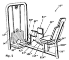
図5に示されている装置10’’’は、使用者の臀部の内転および外旋を実行する際に使用者の筋肉が生み出す力に抵抗するようになっている。この動作は、例えば、サッカーにおいて選手が自分の足の内側でボールをパスする場合に見られる。
The
この装置は、ウェイトスタック14’’’を収容するフレームワーク12’’’を備える。略水平な細長い延長部13’’’の第1の端部は、フレームワーク12’’’のベースの中間点に対して略垂直に配置されている。延長部13’’’の他端には、略垂直な支柱26’’’が設けられており、該支柱26’’’は、シート部24’’’の後部を支持している。シート部24’’’は、使用者が、この装置を使用するときにウェイトスタック14’’’の方を向くように配置されている。
The apparatus comprises a
略垂直な脚部82A’’’および82B’’’は、延長部の上面の、軸線に沿った中心線の両側に1つずつ、細長い延長部13’’’の長手方向に沿って配置されている。垂直な脚部82A’’’および82B’’’は、シート部24’’’の前部を支持している。脚部82A’’’および82B’’’には、それぞれの可動セクション36A’’’および36B’’’が枢動可能に取り付けられており、可動セクション36A’’’および36B’’’は、ウェイトスタック14’’’に向かって延長部13’’’と略平行に延びている。各可動セクションは、第1の可動部分38’’’を備え、第1の可動部分38’’’は、一端において脚部82’’’と枢動可能に連結されており、上向きの角度で延び、他端に隣接する膝支持部84’’’を備える。第1の可動部分38’’’の他端には、第2の可動部分42’’’が、枢動部44’’’を介して連結されており、下方に向かって略垂直に延びている。足支持部86’’’が、第2の可動部分42’’’の他端に取り付けられている。第1の可動部分38’’’は、水平面において回転し、すなわち、略水平な平面において弧を描いてスイングし、第2の可動部42’’’は、冠状面において、略垂直な位置から、もう一方の第2の可動部分42’’’に向かって水平位置となるまで回転することができる。
The substantially
使用者(図示せず)は、シート部24’’’に座り、自分の脚を可動部分36’’’の外側に揃え、自分の膝を膝支持部84’’’に置き、自分の足のそれぞれを足支持部86’’’に置く。使用者の脚を内転させることによって、使用者の膝は、ウェイトスタック14’’’がもたらす抵抗に抗して、互いにより接近するように動く。臀部のその後の回転は、同様にウェイトスタック14’’’からの抵抗に抗して、略垂直な位置からより水平な位置に足をスイングさせる。
The user (not shown) sits on the
図6は、本発明の部分のさらなる実施形態を示しており、これは、例えば、図1に示されているような装置に適用されてもよいが、これまでに説明した実施形態のいずれにも適用することができる。第1の可動部分38*は、枢動部40*によってフレームワーク(図示せず)と連結されている。枢動部44*によって第1の可動部分38*の他端に枢動可能に連結されているのは、第2の可動部分42*である。カム50*は、第1の可動部分38*の長手方向からずれた位置で第1の可動部分38*に取り付けられている。
FIG. 6 shows a further embodiment of the part of the present invention, which may be applied, for example, to an apparatus as shown in FIG. 1, but in any of the embodiments described so far. Can also be applied. The first
第1の部分38*の長手方向のほぼ中程に、第1の歯車90*があり、第1の歯車90*は、その中心の周りを回転することができる。カム50*の軸線には、第2の歯車92*が設けられており、第2の歯車92*は、第1の歯車90*から離間され、カム50*が回転したときに第2の歯車も回転するようにカム50*に固定されている。三位置ギヤボックスが設けられており、該三位置ギヤボックスは、第1の歯車90*および第2の歯車92*の軸線を結ぶ想像線の一方の側に第3の歯車94*を備え、第1の歯車90*および第2の歯車92*を結ぶ想像線の反対側に、互いに係合されて配置された第4の歯車96*および第5の歯車98*を備える。ギヤボックスが、第1の位置に配置されている場合は、第3の歯車94*は、第1の歯車90*および第2の歯車92*の双方と係合し、第2の位置(図示せず)に配置されている場合は、第4の歯車96*は、第2の歯車92*と係合し、第5の歯車98*は、第1の歯車90*と係合し、第3の位置(図示せず)に配置されている場合は、ギヤボックスの歯車94*、96*、および98*のいずれも、第1の歯車90*または第2の歯車92*と係合しない。第1の歯車90*は、第2の可動部分42*が枢動部44*を中心に時計回りに回転するときに、歯車90*も同様に時計回りに回転するように、第2の可動部分42*と連動されている。このリンクは、枢動部44*と同軸に配置され、かつ第2の可動部分42*に取り付けられるさらなる歯車(図示せず)と連結されるチェーン100*によって形成されてもよい。ケーシング(点線102*によって示されている)は、異物によりギヤボックス内の歯車が動かなくなるリスクを低減するために設けられている。長さXは、使用者の様々な腕の長さに合わせて調整されるよう第1の可動部分38*の長さを調整するための手段によってもたらされる。カム50*は、ケーブル104*を介してウェイトスタック(図示せず)に取り付けられている。
There is a
ギヤボックスの第1の位置では、第1の歯車90*が、反時計回りに回転するとき、第3の歯車94*によって形成されたリンクにより第2の歯車92*も同様に反時計回りに回転する。ギヤボックスの第2の位置では、第1の歯車90*が、反時計回り方向に回転するとき、第2の歯車92*は、第4の歯車96*および第5の歯車98*によって形成されたこれらの間のリンクにより、時計回り方向に回転する。すなわち、このリンクは、第1の90*に対して第2の歯車92*の回転方向を反転させる。ギヤボックスが、第3の位置またはニュートラルな位置にある場合は、ギヤボックスの歯車うちのいずれも、第1の歯車90*および/または第2の歯車92*と係合しておらず、したがって、第2の可動部分42*は、カム50*に影響を与えることなく調整することができる。
In the first position of the gearbox, when the
図6のギヤアセンブリを導入することにより、「ニュートラルポジション」および「バックギヤ」の実現が可能となり、この結果、本装置を様々な方法で使用することが可能となる。例として、図1に示されている装置の第2の部分42の動作を反転させることができることが望ましい場合がある。この場合、第2の部分42の開始位置は、第1の部分38に対して略垂直である。このような配置では、全可動域にわたって該装置を伸展させることによって、三頭筋がエクササイズされる。このような反転は、「チェストプレス」動作を「チェストフライ」動作に変換するために使用されてもよい。これにより、本装置は、拮抗筋(antagonistic pair)をエクササイズするのにより適することが可能となり、この結果、1つのマシンによって2つ以上のエクササイズを行うことができるようになるため、固定ウェイトマシンに必要とされる床面積が低減される。
By introducing the gear assembly of FIG. 6, it is possible to realize a “neutral position” and a “back gear”, and as a result, the apparatus can be used in various ways. As an example, it may be desirable to be able to reverse the operation of the
図7は、固定ウェイトエクササイズマシン110を示している。固定ウェイトエクササイズマシン110は、図1に示されているものと同様であり、この実施形態と同様の仕方で機能するが、図7に示されているマシン110は、図1に示されているマシン10に優るいくつかの付加的な特徴を有する。器具110は、ウェイトスタック114を収容するフレームワーク112を備え、ウェイトスタック114は、図1に示されているのと同様の仕方で垂直シャフト(図示せず)と選択的に連結されるウェイトプレート116を備える。
FIG. 7 shows a fixed weight exercise machine 110. The fixed weight exercise machine 110 is similar to that shown in FIG. 1 and functions in a manner similar to this embodiment, but the machine 110 shown in FIG. 7 is shown in FIG. It has some additional features over the
シート部124が設けられており、シート部124の後側は、垂直な支柱126と摺動可能に連結されており、シート部124の下からは、略垂直な脚部125が延びている。シート部124は、所望の高さでシート部124をロックするピン127を用いて、高さ調整可能である。
A seat portion 124 is provided, and a rear side of the seat portion 124 is slidably connected to a
図1の横ビーム32と同様であり、同じ機能を実行する横材132は、中央セクション132aを備える。スリーブ132bおよび132cは、中央セクション132aの各端部と係合しており、中央セクション132aに沿って摺動することができる。螺合された調整部材133は、フレームワーク112と連結されており、また、中央セクション132aに対するスリーブ132bおよび132cの位置を制御するために、スリーブ132bおよび132cとも連結されている。螺合された調整部材133を回転させると、中央セクション132aに対するスリーブ132bおよび132cの位置が変化する。付勢された張力アセンブリの形態をとってもよいテンショナ装置135は、スリーブ132bおよび132cの位置およびこれらの間の距離に関係なく、ケーブルを確実にピンと張り続けるために設けられている。図1のセクション36と同様の可動セクション136は、使用の際に使用者の方に向かって延びるように、延長部134を介してスリーブ132cと連結されている。したがって、調整部材133を用いてスリーブ132cの横位置を調整することにより、可動セクション136間の距離を変更することが可能であり、この結果、様々なサイズの使用者たちが、単一のマシンを使用することが可能となる。第2の螺合された部材(図示せず)は、他方のスリーブ132bの独立調整を可能とするために設けられている。
A
マシン110は、スリーブ132bおよび132cの独立調整が、スリーブ132bおよび132cの双方の横位置を制御する2つの調整部材133を用いることによって可能であるように構成され得ることが理解されよう。
It will be appreciated that the machine 110 may be configured such that independent adjustment of the
延長部134は、スリーブ132bおよび132cに固定して取り付けられており、使用者の所望の位置に向かって突出している。しかしながら、これらの延長部は、図示されていないさらなる実施形態では、固定して取り付けられるのではなく、枢動可能に連結されてもよい。図1の部分38と同様の第1の可動部分138のそれぞれが、設けられており、枢動部140において延長部134と連結され、枢動部140から延びている。第1の可動部分138には、第1の長さ調整機構139が設けられている。この機構は、スリーブ139aを備え、スリーブ139aは、該スリーブ139a内に収容された細長い部分139bを有する。細長い部分139bは、スリーブ139a内で摺動することができ、また、回転つまみ139cを用いることによって調整される。回転つまみ139cは、スリーブ139aの内または外へ細長い部分を摺動させ、これにより、第1の可動部分138の長さを調整する。テンショナ139dは、細長い部分139bの位置を調整するときにケーブル(図示せず)の張力を確実に維持するために設けられている。テンショナ139dは、付勢され、蝶番で連結された2つの部品からなるアーム部材の形態をしている。
The
第2の可動部分142は、枢動部144において第1の可動部分138と連結されており、同様に、図1の部分42に相当する。これらの第2の可動部分142には、調整機構145が設けられており、調整機構145は、摺動可能セクション145aを備え、摺動可能セクション145aは、細長い部分145bを囲んでおり、また、摺動可能セクション145aを適切な位置に保持するロッキングシステムを有する。調整制御つまみであって、回転させると、摺動可能セクション145aに対する細長い部分145bの位置が調整される調整制御つまみが設けられており、この結果、第2の可動部分142の長さを制御することが可能になっている。
The second
調整機構は、使用者の肩幅、上腕の長さ、および前腕の長さを考慮したものであり、サイズおよび体形が様々の使用者がマシン110を使用することを可能にする。この結果、マシン110は、使用者の関節との適切な位置合わせを確実にするために変更することができるため、けがのリスクが減少する。 The adjustment mechanism takes into account the user's shoulder width, upper arm length, and forearm length, allowing users of various sizes and shapes to use the machine 110. As a result, the machine 110 can be modified to ensure proper alignment with the user's joint, thus reducing the risk of injury.
回転可能ハンドグリップ146は、第2の可動部分142の端部と連結されており、このため、使用者は、自分の手首に回転ストレスが加えられることなく、その可動域の全体にわたって快適に動くことが可能となっている。
The
可動域リミッタ155aおよび155bは、可動部分138および142がそれぞれ、所定の位置を越えて伸展されないことを確実にしている。これらリミッタは、1つの部分に取り付けられるプレート部材を備え、該プレート部材中には溝があって、ピンが、該溝と係合される。これにより、使用者が、その可動域を越えて伸ばし過ぎることが防止され、マシン110に損害を与えるリスクが低減される。あるいは、1つの可動部分は、プレート部材の孔に別個のピンを通すことによって適切な位置に固定され、この結果、この部分が適切な位置にロックされてもよい。これにより、使用者が、同時に2つの関節をエクササイズするのではなく、単一の関節にマシンの動作を制限することが可能となる。
Movable range limiters 155a and 155b ensure that
器具110は、器具110の調整可能な特徴を考慮に入れながら、図1に示されている器具10と同様の方法で操作される。
The instrument 110 is operated in a manner similar to the
図8は、他の図面に示されているエクササイズマシンの他の実施形態と共通の多くの特徴を有する、肩の外旋用のマシン210を示している。フレームワーク212は、図7に示されているのと同様のウェイトスタック(図示せず)を収容している。マシン210は、調整可能なシート部224を備え、調整可能なシート部224は、略垂直な脚部225を有し、略垂直な支柱226に摺動可能に係合されている。ロッキングピン227が、シート部224の高さを設定し、これを適切な位置に保持するために設けられている。
FIG. 8 shows a shoulder
横材232が設けられており、図7に示されているのと同様の機構が使用されている。スリーブ232bおよび232cは、中央セクション232a上に摺動可能に配置されている。図7のマシンと同様に、略水平な中央セクション232aの長手方向におけるスリーブ232bおよび232cの位置は、肩幅の異なる使用者に対応するために調整されてもよい。回転調整部材233は、スリーブ232bおよび232cの位置を制御するために使用される。
A cross member 232 is provided and a mechanism similar to that shown in FIG. 7 is used.
延長部234が、スリーブ232bおよび232cのそれぞれに設けられており、さらに、延長部234は、それぞれの可動セクション236と連結されている。可動セクション236の第1の部分238は、枢動連結部240において、延長部234と連結されている。第2の可動部分242は、枢動部244において第1の可動部分と連結されており、移動軸カム(moving axis cam)250は、同じ位置において第2の可動部分242と連結されている。第2の可動部分242の長さ調整は、回転つまみを使用することによって、使用の際に使用者の肘の位置に相当する受動的な肘調整手段253のジョイントにおいて行われてもよい。
An
張力装置は、マシン210を使用者に適合するよう調整している間、ケーブルを確実にピンと張り続けるために設けられている。
A tensioning device is provided to ensure that the cable remains taut while adjusting the
可動域リミッタ255aおよび255bは、第1の部分および第2の部分が所定の位置を越えて進むことを防止するために設けられている。
The
図9は、ウェイトスタック314を収容するフレームワーク312を備えるハムストリングエクササイズマシン310を示している。フレームワーク312は、事実上2つのAフレームの形態をしており、2つのAフレームは、それらの頂点において横材により互いに連結されており、安定性および剛性を高めるために様々な他の点において互いに連結されている。フレームワークの上面の一方には、使用者支持部324が設けられている。フレームワーク312の同じ面の、支持部324よりも下の部分では、2つのハンドル部346が、フレームワーク312のそれぞれの効果的なAフレームと連結されている。
FIG. 9 shows a
それぞれの効果的なAフレームの頂点は、それぞれ、略垂直な延長セクション334の下端と連結されている。枢動可能に連結された可動セクション336は、延長セクション334の他端に取り付けられている。可動セクションは、第1の可動部分338を備え、第1の可動部分338の一端は、枢動部340において延長セクション334と連結されている。第1の可動部分338の他端は、枢動部344において第2の可動部分342と連結されている。第2の可動部分342は、同じ枢動点344において、枢動部を介して、移動軸カム350と連結されている。
Each effective A-frame vertex is connected to the lower end of a substantially
第1の可動部分338は、第1のセクション338aを備え、第1のセクション338a中に、第2のセクション338bが摺動可能に受けられており、また、第1の可動部分338は、ロッキング手段338cによって適切な位置に保持することができる。ロッキング手段338cは、回転可能なハンドルの形態をしており、この場合、一方向への回転により、第1のセクション338aが、第2のセクション338bにおいて伸ばされるか、または、縮められることが可能となっている。第1のセクション338aおよび第2のセクション338bの構成は、第1の可動部分338の長さが調整されることを可能とする。脚パッド339は、第2のセクション338bの長手方向に沿って設けられている。第1の可動部分338には、第1の可動部338分の長さを調整する際にケーブル(図示せず)をピンと張り続けるために、リンクテンショナ335が設けられている。
The first
第2の可動部分342の下端には、調整可能な足プレート325が設けられており、第2の可動部分に対して調整可能な足プレート325の位置は、ピンロッキング機構を用いることによって変更されてもよい。
An
ステップ360は、使用者がマシン310に乗り降りするのを助けるために、可動セクション336間に設けられている。
Step 360 is provided between the movable sections 336 to help the user get on and off the
調整可能な可動域リミッタ355は、可動セクション336の可動域を制限するために設けられている。これらは、可動部分338および342と連結され、かつ溝を有するプレート部材と、該溝に挿入することによって、プレートの可能な動作を制限することができるピンとを備える。付加的なロッキング手段が、単一の関節のエクササイズを可能とする目的で適切な位置に可動部分をロックするために設けられている。
An adjustable range of
使用の際、使用者は、マシン310に乗り込み、フレームワーク312上にうつぶせになる。使用者は、自分の胴体を使用者支持部324上に配置し、ハンドル346を握る。第1の可動部分338は、脚パッド339が使用者の大腿部の下に配置されるように調整すべきである。次に、足プレート325は、使用者の足が適切な位置に配置されること、および、第2の可動部分342が、マシン310を操作するのに十分な長さとなることを確実にするために調整される。次に、使用者は、ウェイトスタックの抵抗力に抗して自分のハムストリングをエクササイズする。第1の可動部分と第2の可動部分とを組み合わせて使用することにより、使用者の臀部およびハムストリング筋の全可動域のエクササイズが可能となる。
In use, the user gets into the
図10および図11は、例示的な可動セクション436をより詳細に示している。可動セクションは、第2の可動部分442および枢動部440と連結された第1の可動部分438を備える。枢動部444は、一方が回転するとき他方も回転するように、第2の可動部分と移動軸カム450とを連結している。案内滑車449および定滑車451は、それぞれ、延長セクション434および第1の可動部分438に設けられている。ケーブル(図示せず)は、案内滑車449および定滑車451を通り、カム450まで通っている。テンショナ機構435は、第1の可動部分438の長さを調整する際にケーブルの張力を保持するために、ケーブルの経路に沿って設けられている。可動域リミッタ455は、マシンおよび/または使用者に損害を与えるリスクを低減する目的で、延長セクション434と第1の可動部分438とのジョイントおよび第1の可動部分と第2の可動部分442とのジョイントの動作を制限するために設けられている。
10 and 11 show an exemplary
案内滑車は、カムとウェイトスタックとの間でケーブルを案内するために、図面に開示されている器具上に配置されている。様々なパッドは、快適さおよび支持を補助するためにエクササイズマシン上に配置されている。 A guide pulley is arranged on the instrument disclosed in the drawing for guiding the cable between the cam and the weight stack. Various pads are placed on the exercise machine to aid comfort and support.
可動域リミッタは、エクササイズマシンのジョイントをロックすることによって、第1の可動部分または第2の可動部分を適切な位置にロックするために配置されてもよい。これにより、使用者が、単一の関節を単独でエクササイズすることが可能となる。 The range of motion limiter may be arranged to lock the first movable part or the second movable part in place by locking the joint of the exercise machine. This allows the user to exercise a single joint independently.
第1の可動部分および第2の可動部分の長さを調整するためにピンロッキング機構を使用することが望ましい場合がある。 It may be desirable to use a pin locking mechanism to adjust the length of the first and second movable parts.
カムが、第1の部分38と第2の部分42との間の枢動部と同軸であり、第2の部分に取り付けられている場合、第1の部分38において抵抗力に打ち勝つために必要とされるトルクおよび/または直線力は、第2の部分42よりも大きくなる。例えば図5の場合のように多軸エクササイズが行われる場合、第1の部分38’’’において抵抗力に打ち勝つために必要とされる力は、カム50’’’の半径が36A’’’の長さよりも短いとき、第2の部分42’’’において必要とされるものよりも大きくなる。
Necessary to overcome the resistance force in the
抵抗力に打ち勝つために必要とされるトルクを調整するために、カムは、可動セクションの第1の部分および/または第2の部分の長手方向に沿って移動されてもよい。この移動は、1つ以上の所定の個々の位置を経由して行われてもよいし、または、連続的な摺動配置システムに沿って行われてもよい。カムの位置を調整することによって、可動セクション36のそれぞれの部分38および42を動かすために必要とされるトルクは、第1の部分において必要とされるトルクが、所望のエクササイズに応じて、第2の部分よりも大きくまたは小さくなるように調整することができる。例えば、図3に示されている実施形態の場合、首を緊張させずに、背中によって、必要とされるよりも大きなトルクが加えられるように、可動セクションの第2の部分のトルクを、可動セクションの第1の部分よりも大幅に小さくすることが望ましい場合がある。
In order to adjust the torque required to overcome the resistance force, the cam may be moved along the length of the first and / or second part of the movable section. This movement may take place via one or more predetermined individual positions, or may take place along a continuous sliding arrangement system. By adjusting the cam position, the torque required to move the
カムは、通常、枢動部44と同軸に配置されるが、枢動部44に対して垂直に、または、双方が任意の角度をなすように配置されてもよい。このような角度にカムを設定することによって、抵抗が、第2の部分42の動作に対して加えられ、これにより、使用者の関節の回転動作が可能となる。必要とされる並進動作および回転動作の適切な度合いを実現するために、第2の部材に対して垂直な角度と第2の部材に平行な角度との間にこの角度を設定することが望ましい場合がある。また、第1の部分38の動作中に第2の部分42の角度を一定に保つために、カム上に案内滑車を採用することが望ましい場合がある。この場合、案内部材は、第1の部分38がその枢動部40において枢動した量に応じて、カムを所定の角度回転させる。第1の部分38が内側に移動するとき、例えば、肩の水平内転中にカム50に対するケーブルの角度を維持する案内滑車を第1の部分38に取り付けることが、さらに望ましい場合がある。
The cam is typically arranged coaxially with the
さらなる構造では、カムの回転の中心が、任意の距離だけ枢動部44の軸線からずらされてもよい。これにより、図4に示されているように、異なるカムプロファイルが効果的に形成される。カムは、第1の部分38および/または第2の部分42にフランジを取り付け、これに対してそれぞれのカムを固定することによって、異なる位置に並進されてもよい。恒久的なずれた位置にカムを配置するよりも、枢動部の軸線からずれる量が、連続レールまたは分散した複数の所定の位置を含むレールのいずれかにおいて調整され得るように、調整可能なカムをレールに取り付けることが好適な場合がある。
In a further construction, the center of rotation of the cam may be offset from the axis of the
カムは、第2の部分42が受動的な状態で、可動セクション36の第1の部分38と連結されてもよい。このような構造では、抵抗は、主に第1の部分38を介して感じられ、第2の部分42は、本体部分を自然な位置に維持するために枢動するか、または、回転することができる。例えば、使用者がより快適であり、全体がより自然な経路を辿るように、前腕が回転される一方で、肩が回転されてもよい。
The cam may be coupled to the
本発明の例示的な適用は、以下を含むが、これらに限定されることを意図されてはいない。
足首
・底屈、回内
・背屈、回外
・底屈、回外
・背屈、回内
下腿
・足首の底屈、膝の屈曲
・足首の背屈、膝の伸展
・足首の底屈、膝の伸展
・足首の背屈、膝の屈曲
膝
・屈曲、内旋
・屈曲、外旋
・伸展、内旋
・伸展、外旋
大腿部
・膝の屈曲、臀部の伸展
・膝の伸展、臀部の屈曲
・膝の伸展、臀部の伸展
・膝の屈曲、臀部の屈曲
臀部
・内転、外旋
・外転、内旋
・内転、内旋
・外転、外旋
・伸展、膝の屈曲
・臀部の屈曲、膝の伸展
脊椎
・胸腰椎の側方屈曲
・胸腰椎の回転
・胸腰椎の前方屈曲(腹部)
・首および頭の側方屈曲、屈曲、伸展
・伸展
鎖骨
・肩甲骨の挙上、肩の外転
・肩甲骨の下制、肩の内転
・肩甲骨の外転、肩の水平屈曲
・肩甲骨の内転、肩の水平伸展
肩
・水平外転、外旋
・水平内転、内旋
・外転、外旋
・内転、内旋
上腕
・肩の水平外転、肘の伸展
・肩の水平内転、肘の屈曲
・肩の外転、肘の屈曲
・肩の内転、肘の伸展
・肩の屈曲、肘の屈曲
・肩の伸展、肘の伸展
・肩の水平屈曲、肘の伸展
・肩の水平伸展、肘の屈曲
・肩の外転、肘の伸展
・肩の内転、肘の屈曲
肘
・伸展、回内
・屈曲、回外
前腕
・肘の屈曲、手首の屈曲
・肘の伸展、手首の伸展
Exemplary applications of the present invention include, but are not intended to be limited to:
Ankle ・ Bottom flexion, pronation ・ Dorsal flexion, pronation ・ Bottom flexion, pronation ・ Dorsal flexion, pronation lower leg ・ Ankle sole flexion, knee flexion ・ Ankle dorsiflexion, knee extension Knee extension ・ Ankle dorsiflexion, knee flexion Knee ・ Bending, internal rotation ・ Bending, external rotation ・ Extension, internal rotation ・ Extension, external rotation Thigh ・ Knee flexion, buttocks extension ・ Knee extension, buttocks -Knee extension, buttocks extension-Knee flexion, buttocks flexion Buttocks-Adduction, external rotation-Abduction, internal rotation-Adduction, internal rotation-Abduction, external rotation-Extension, knee flexion- Bend flexion, knee extension Spine-Thoracolumbar spine flexion-Thoracolumbar spine rotation-Thoracolumbar spine forward flexion (abdomen)
-Lateral flexion, flexion, extension of the neck and head-Extension clavicle-Raised scapula, shoulder abduction-Scapular inversion, shoulder adduction-Scapular abduction, horizontal shoulder flexion-Shoulder Scapular adductor, horizontal extension of shoulder Shoulder ・ Horizontal abduction, external rotation ・ Horizontal adduction, internal rotation ・ Abduction, external rotation ・ Addition, internal rotation Upper arm ・ Horizontal abduction of shoulder, extension of elbow Horizontal adduction, elbow flexion-Shoulder abduction, elbow flexion-Shoulder adduction, elbow extension-Shoulder flexion, elbow flexion-Shoulder extension, elbow extension-Horizontal shoulder flexion, elbow extension・ Horizontal extension of the shoulder, flexion of the elbow ・ Shoulder abduction, extension of the elbow ・ Shoulder abduction, flexion of the elbow Elbow ・ Extension, pronation ・ Bend, gyration Forearm Extension, wrist extension
いずれの場合も、動作は、多数の他のさらなる平面において行うことができることが望ましい。例として、肩の水平外転および外旋は、肩の水平外転および伸展の経路を辿ってもよく、双方は、外旋によって組み合わされている。 In any case, it is desirable that the operation can be performed in a number of other additional planes. As an example, horizontal abduction and rotation of the shoulder may follow the path of horizontal abduction and extension of the shoulder, both being combined by external rotation.
さらなる動作、例えば、ハンドルまたは足支持部(存在する場合)の受動的な回転が、装置に導入されてもよい。あるいは、ハンドルまたは足支持部に抵抗力が、好適には三次元カムの使用によって、加えられてもよい。 Further actions, such as passive rotation of the handle or foot support (if present) may be introduced into the device. Alternatively, a resistance force may be applied to the handle or foot support, preferably by use of a three-dimensional cam.
少なくとも1つの滑車が、抵抗力と可動セクションとをリンクするケーブルを案内するために枢動されてもよい。これにより、ケーブルが常に、可動域にわたってそれぞれのカムに向けられることが可能となる。 At least one pulley may be pivoted to guide a cable that links the resistance and the movable section. This allows the cable to always be directed to each cam over the range of motion.
連結ケーブルをカムに案内する滑車は、第1の部分の全可動域にわたって回転トルクを与えるように配置されてもよい。このことは、滑車の回転軸線と第1の連結部の回転軸線とを同軸に配置することによって行われてもよい。あるいは、滑車がずらされてもよい。 The pulley that guides the connecting cable to the cam may be arranged to provide rotational torque over the entire range of motion of the first part. This may be done by arranging the rotation axis of the pulley and the rotation axis of the first connecting part coaxially. Alternatively, the pulley may be shifted.
マシンが、例えば図4の場合のように、外側に伸展した略水平な腕の開始位置を有し、矢状面に向かい、さらに、肘の屈曲と共に冠状面に向かう腕の内転をエクササイズする場合、第1の可動部分38’’と第2の可動部分42’’との連結部は、「玉継ぎ手」であることが望ましい場合がある。この結果、全可動域にわたって腕のより自然な動作(前腕の回転を含む)が可能となる。これにより、フォアハンドショット中のテニスラケット動作が反復される。あるいは、第1の可動部分と第2の可動部分との連結部は、複数の平面における回転を行うために2つ以上の枢動部、好ましくは、互いに直交するよう配置された2つの枢動部を備えてもよい。このことは、本装置の任意の連結部に適用されてもよい。
The machine exercises the adduction of the arm with the starting position of a generally horizontal arm extending outward, toward the sagittal plane and further to the coronal plane with elbow flexion, as in FIG. 4, for example In this case, it may be desirable that the connection between the first
カムが第1の部分の長手方向に沿った位置に配置された、本発明の実施形態では、カムと第2の連結部との距離は、第1の連結部と第2の連結部との距離を調整するために変更されてもよい。これにより、本装置は、使用者の手足の様々な長さに適合するよう調整可能である。同様に、ハンドル(存在する場合)と第2の連結部との距離も調整されてもよい。これらの調整は、第1の部分および第2の部分の相対的長さを変更するために1回の調整だけが必要なように、互いに結合されてもよい。本装置の他の部分は、使用者の様々なサイズを考慮に入れて調整可能であることが好ましい場合がある。カムは、部分のうちの1つの長手方向に沿って配置され、さらに、一方の側から見た場合に同じ部分の軸線からずれていてもよく、この場合、カムの位置(および場合によってはカムの軸線)が、第1の連結部および第2の連結部と共に三角形を形成する。二次元または三次元的に可動部分のうちの1つの線からカムの位置をずらすことは、可動セクションが受ける結果として生じる抵抗力を変化させる助けとなり得る。 In the embodiment of the present invention in which the cam is disposed at a position along the longitudinal direction of the first portion, the distance between the cam and the second connecting portion is the distance between the first connecting portion and the second connecting portion. It may be changed to adjust the distance. This allows the device to be adjusted to fit different lengths of the user's limbs. Similarly, the distance between the handle (if present) and the second connecting portion may be adjusted. These adjustments may be coupled together so that only one adjustment is required to change the relative lengths of the first and second portions. It may be preferred that other parts of the device can be adjusted to take into account various user sizes. The cam may be disposed along the longitudinal direction of one of the portions and may be offset from the axis of the same portion when viewed from one side, in which case the cam position (and possibly the cam) Together with the first connecting portion and the second connecting portion form a triangle. Shifting the position of the cam from one line of the movable part in two or three dimensions can help to change the resulting resistance force experienced by the movable section.
本装置の使用の際にカムを移動させるために必要とされるトルクを増減するために、カムにウェイト(またはカウンタウェイト)が設けられてもよい。 In order to increase or decrease the torque required to move the cam when using the apparatus, a weight (or counterweight) may be provided on the cam.
枢動部40および44は、例えば玉継ぎ手による枢動機構を用いて、複数の平面における変位を可能としてもよい。これにより、様々な自由度の動作が実現される。このことは、例えば、図5に示されている実施形態と組み合わせた場合に有用な場合がある。この場合、膝の関節は、使用者の動作(より詳しくはボールをパスする動作に類似した)中に伸展されてもよい。
The
記載した実施形態は、シート部の使用について言及しているが、使用者が、立った姿勢か、または、仰向けの姿勢(横になることを含む)をとることによって、シートの必要性が取り除かれることが望ましい場合がある。 Although the described embodiment refers to the use of the seat portion, the need for the seat is eliminated by the user taking a standing or supine position (including lying down). It may be desirable to be
開示した使用に加えて、または、代案として、本装置は、循環器系のエクササイズに使用されてもよい。 In addition to or as an alternative to the disclosed use, the apparatus may be used for cardiovascular exercises.
可動部分は、その各端部において連結されているものとして説明されてもよいが、このことは、端部の近傍、または、端部の領域を意味することが意図されている。また、このことは、例えば、部分が、第2の部分が、必ずしも端部においてではないが、第1の部分の長手方向に沿って連結されることをもたらすような特定の方法で形作られる場合に、第2の部分の長手方向に沿うことも意味し得る。このことは、第2の部分が第1の部分の端部と連結されない場合に、第2の部分が、第1の部分の長さの後ろ半分において連結される場合、好適である。 Although the movable parts may be described as being connected at each end thereof, this is intended to mean the vicinity of the end or the region of the end. This may also be the case, for example, when the part is shaped in a particular way that results in the second part being connected along the longitudinal direction of the first part, but not necessarily at the end. In addition, it may mean along the longitudinal direction of the second portion. This is preferred when the second part is connected in the rear half of the length of the first part when the second part is not connected with the end of the first part.
抵抗は、例えば、ウェイトスタック、フライホイール、ピストン・シリンダ構成、もしくは抵抗バンド、またはこれらの組合せによって与えられてもよい。抵抗は、ケーブルを介するのではなく、第1の可動部分および/または第2の可動部分に直接取り付けられるウェイトの形態をとってもよい。ピストン・シリンダ構成は、第1の部分に取り付けられ、かつ該第1の部分の動作に抵抗するピストンおよびシリンダと、第2の部分に取り付けられ、かつ該第2の部分の動作に抵抗する第2のピストン・シリンダ構成とを備えてもよい。明らかに、他の抵抗手段が、ピストン・シリンダ構成の位置に使用されてもよい(例えば、それぞれの部分に接続された2つのウェイトスタック)。抵抗は、筋肉が、所定の位置に到達したときに、過負荷をかけられ得るように、可動域の間に可変であってもよい。このことは、ピストン・シリンダ構成の使用、または、ウェイトスタックへの重量の追加によって行われてもよい。あるいは、抵抗の増減は、カムの使用によって行われてもよい。カムを特定のプロファイルにすることによって、筋肉の作業負荷、偏心抵抗力を変更するために抵抗を大幅に増減することが可能であってもよい。カムの半径および/またはカムの位置を調整することによって、抵抗力に打ち勝つために必要とされるトルクも調整されるが、このとき、カムの位置を調整するために第1の部分および第2の部分の長さが調整される。 The resistance may be provided, for example, by a weight stack, flywheel, piston / cylinder configuration, or resistance band, or a combination thereof. The resistor may take the form of a weight that is attached directly to the first and / or second movable part rather than through the cable. The piston / cylinder arrangement is attached to the first part and resists movement of the first part, and the piston and cylinder arrangement is attached to the second part and resists movement of the second part. Two piston / cylinder configurations may be provided. Obviously, other resistance means may be used in the position of the piston / cylinder arrangement (eg two weight stacks connected to each part). The resistance may be variable during the range of motion so that the muscle can be overloaded when it reaches a predetermined position. This may be done by using a piston / cylinder arrangement or by adding weight to the weight stack. Alternatively, the resistance may be increased or decreased by using a cam. By making the cam a specific profile, it may be possible to greatly increase or decrease the resistance to change the muscular workload, eccentric resistance. By adjusting the cam radius and / or the cam position, the torque required to overcome the resistance force is also adjusted, at which time the first part and the second part are adjusted to adjust the cam position. The length of the part is adjusted.
リバーシブルバンド(reversible band)またはピストン・シリンダ構成を含むが、これに限定されない他のリンク機構が、図6に例示されているようなギヤボックス機構を形成するために使用されてもよい。 Other linkage mechanisms, including but not limited to a reversible band or piston / cylinder configuration, may be used to form a gearbox mechanism as illustrated in FIG.
「固定ウェイト」は、使用者が制限されずに任意の方向または組み合わされた様々な方向に動くことができるフリーウェイトとは異なり、本装置の操作中に、抵抗が、滑車位置を利用して可動セクションに加えられることを意味するためのものである。 “Fixed weights” are different from free weights that allow the user to move in any direction or any combination of directions without restriction, and during operation of the device, the resistance will utilize the pulley position. It means to be added to the movable section.
「ケーブル」は、チェーン、ロープ、ベルト、ワイヤ、および他の接続手段を含むことが意図されている。接続手段は、抵抗力と可動セクションとをリンクする1つ以上のギヤまたはコグを備えてもよい。 “Cable” is intended to include chains, ropes, belts, wires, and other connection means. The connecting means may comprise one or more gears or cogs that link the resistance and the movable section.
「矢状面」、「冠状面」、および「水平面」は、「傍矢状面」と平行な平面を意味するためのものであり、場合によって「傍矢状面」等と呼ばれる。 “Sagittal plane”, “coronal plane”, and “horizontal plane” are intended to mean a plane parallel to “para-sagittal plane”, and are sometimes called “para-sagittal plane” or the like.
「スイング」は、直線運動および/または角運動を包含する動作を含むことが意図されている。したがって、第1の可動部分は、直線的に可動であってもよく、第2の部分は、角度的に可動であってもよい。 “Swing” is intended to include motion involving linear and / or angular motion. Thus, the first movable part may be linearly movable and the second part may be angularly movable.
第1の可動部分および第2の可動部分は、実質的に細長く、また、使用者の手足または胴体部分の位置を反映するように配置されてもよい。「細長い」は、部分の長さが、他の寸法よりも大幅に長いことを意味するためのものである。 The first movable portion and the second movable portion are substantially elongated and may be arranged to reflect the position of the user's limb or torso portion. “Elongated” is intended to mean that the length of the part is significantly longer than other dimensions.
ギヤボックス構成を使用することによって、本明細書に記載されている構成の少なくともいくつかの動作を反転させることが可能である。これにより、単一のマシンを用いてエクササイズすることのできる筋肉の数が増加する。 By using a gearbox configuration, it is possible to reverse at least some operations of the configuration described herein. This increases the number of muscles that can be exercised using a single machine.
Claims (15)
Applications Claiming Priority (3)
| Application Number | Priority Date | Filing Date | Title |
|---|---|---|---|
| GB1103990.6 | 2011-03-09 | ||
| GB1103990.6A GB2488988B (en) | 2011-03-09 | 2011-03-09 | Improved exercise apparatus |
| PCT/GB2012/050504 WO2012120299A1 (en) | 2011-03-09 | 2012-03-07 | Improved exercise apparatus |
Publications (3)
| Publication Number | Publication Date |
|---|---|
| JP2014507239A JP2014507239A (en) | 2014-03-27 |
| JP2014507239A5 JP2014507239A5 (en) | 2016-08-18 |
| JP5995878B2 true JP5995878B2 (en) | 2016-09-21 |
Family
ID=43923434
Family Applications (1)
| Application Number | Title | Priority Date | Filing Date |
|---|---|---|---|
| JP2013557172A Expired - Fee Related JP5995878B2 (en) | 2011-03-09 | 2012-03-07 | Improved exercise equipment |
Country Status (11)
| Country | Link |
|---|---|
| US (1) | US9776034B2 (en) |
| EP (1) | EP2683451B1 (en) |
| JP (1) | JP5995878B2 (en) |
| CN (1) | CN103533992B (en) |
| AU (1) | AU2012226547B2 (en) |
| BR (1) | BR112013023066B1 (en) |
| CA (1) | CA2865689C (en) |
| GB (1) | GB2488988B (en) |
| RU (1) | RU2606944C2 (en) |
| TW (1) | TWI537027B (en) |
| WO (1) | WO2012120299A1 (en) |
Families Citing this family (15)
| Publication number | Priority date | Publication date | Assignee | Title |
|---|---|---|---|---|
| CN104922854A (en) * | 2014-03-18 | 2015-09-23 | 青岛瑞箭机电工程技术有限公司 | Device for exercising muscles through lifting bent arms |
| US9446284B2 (en) * | 2014-03-20 | 2016-09-20 | Kyle Michael Sela | Squat exercising |
| CN104941117A (en) * | 2014-03-26 | 2015-09-30 | 青岛瑞箭机电工程技术有限公司 | Pectoralis major muscle training device |
| CN105080037A (en) * | 2014-04-28 | 2015-11-25 | 青岛瑞箭机电工程技术有限公司 | Arm muscle recovery exerciser |
| KR101653480B1 (en) | 2015-01-13 | 2016-09-01 | 오동엽 | Single nucleotide polymorphism marker in ADAM15 gene for diagnosis of meat quality in Hanwoo and method for diagnosis of meat quality in Hanwoo using same marker |
| CN106540403A (en) * | 2015-09-16 | 2017-03-29 | 石磊 | Fitness equipment |
| US10434360B1 (en) | 2015-10-12 | 2019-10-08 | Eric Hosfeld | Multi-joint exercise machine |
| CN105311795A (en) * | 2015-11-06 | 2016-02-10 | 天津吉展科技发展有限公司 | Dual-purpose arm-power body builder with folding and sliding functions |
| US10953267B2 (en) * | 2015-12-31 | 2021-03-23 | Nautilus, Inc. | Exercise machine having non-matched cable pairing |
| FI126770B (en) | 2016-04-04 | 2017-05-15 | David Health Solutions Ltd | Rehabilitation device and its use for shoulder area exercise |
| RU2681101C1 (en) * | 2018-04-06 | 2019-03-04 | Федеральное государственное бюджетное образовательное учреждение высшего образования "Казанский государственный энергетический университет" (ФГБОУ ВО "КГЭУ") | Power station |
| KR102225269B1 (en) * | 2020-10-13 | 2021-03-09 | (주)뉴텍웰니스 | Arm curl fitness apparatus |
| CN112891850A (en) * | 2021-01-20 | 2021-06-04 | 吉林体育学院 | Physical training device capable of relieving anxiety psychology |
| CN114053663B (en) * | 2021-12-07 | 2022-09-16 | 宋建伟 | Skeletal muscle exercise and recovery instrument for bone fracture patients |
| US11806578B2 (en) * | 2022-04-05 | 2023-11-07 | Greogry H. Rose | Rotator cuff exercise machine |
Family Cites Families (28)
| Publication number | Priority date | Publication date | Assignee | Title |
|---|---|---|---|---|
| US4511137A (en) * | 1983-01-20 | 1985-04-16 | Nautilus Sports/Medical Industries, Inc. | Compound weight lifting exercising machine |
| GB8823855D0 (en) * | 1988-10-11 | 1988-11-16 | Close J C | Ultra-arm machine |
| GB2232089A (en) * | 1989-05-27 | 1990-12-05 | Liu Chun Chia | Multipurpose physical conditioning apparatus |
| JP2508350Y2 (en) * | 1990-01-31 | 1996-08-21 | ハラシマ工業株式会社 | Body exerciser |
| US5042799A (en) | 1990-10-09 | 1991-08-27 | Stanley Ronald F | Portable arm and leg exercise device utilizing a friction force resister |
| GB2249733B (en) * | 1990-11-13 | 1994-11-23 | Vincent Frank Basile | A bicep exercise machine |
| JP2718597B2 (en) * | 1992-06-26 | 1998-02-25 | 有限会社華陽総業 | Sport exercise equipment |
| US5486150A (en) * | 1993-04-30 | 1996-01-23 | Randolph; Lucian | Exercise system, apparatus and method |
| CN1102352A (en) * | 1993-11-10 | 1995-05-10 | 斯坦尼那产品公司 | Multiple function exercise apparatus |
| EP0956105A4 (en) * | 1995-03-01 | 2003-01-02 | Cybex Int Inc | Plate-loaded shoulder press exercise machine and method of exercise |
| US5558624A (en) * | 1995-06-22 | 1996-09-24 | Dynasplint Systems, Inc. | Shoulder physical therapy device |
| US5897467A (en) * | 1997-05-29 | 1999-04-27 | Precor Incorporated | Articulated upper arm exerciser |
| US5810701A (en) * | 1997-06-17 | 1998-09-22 | Northland Industries, Inc. | Motion translation arrangement for exercise machine |
| US6579213B1 (en) * | 2000-02-29 | 2003-06-17 | Hoist Fitness Systems | Exercise arm assembly for exercise machine |
| JP3087941U (en) * | 2002-02-13 | 2002-08-23 | 進村 程 | Abdominal exercise device |
| CN2582665Y (en) * | 2002-12-04 | 2003-10-29 | 山东英克莱集团有限公司 | Butterfly chest expander |
| US7993251B1 (en) * | 2003-08-04 | 2011-08-09 | Hoist Fitness Systems, Inc. | Pectoral fly exercise machine |
| US7901335B2 (en) * | 2003-08-04 | 2011-03-08 | Hoist Fitness Systems, Inc. | Multi-station exercise machine |
| US7645215B2 (en) * | 2005-08-11 | 2010-01-12 | Gordon Joel D | Exercise device |
| US7645216B2 (en) | 2006-05-17 | 2010-01-12 | Kurt William Edeker | Dual cam exercise device method and apparatus |
| GB2440120B (en) | 2006-07-19 | 2009-01-28 | Douglas Higgins | Muscle conditioning apparatus |
| US7553264B2 (en) * | 2007-05-18 | 2009-06-30 | Tuffstuff Fitness Equipment, Inc. | Push/pull exercise apparatus, device, and method |
| EP2164578A4 (en) * | 2007-07-06 | 2013-06-12 | Joseph K Ellis | Dual direction exercise treadmill with moment arm resistance |
| US8057368B1 (en) * | 2007-08-06 | 2011-11-15 | Grzegorz Lyszczarz | Three-point adjustable multi-purpose exercise machine |
| US7771322B1 (en) * | 2008-03-17 | 2010-08-10 | Roger Batca | Fold away wrist roller with shared constant tension line |
| US7833138B1 (en) * | 2008-07-22 | 2010-11-16 | Kent Fulks | Apparatus for bi-directional upper body exercise movements |
| IT1399144B1 (en) * | 2009-07-06 | 2013-04-11 | Berardo | EQUIPMENT FOR PHYSICAL EXERCISE |
| US20130109543A1 (en) * | 2011-10-27 | 2013-05-02 | Gil Reyes | Multiple pulley system exercise device |
-
2011
- 2011-03-09 GB GB1103990.6A patent/GB2488988B/en not_active Expired - Fee Related
-
2012
- 2012-03-07 JP JP2013557172A patent/JP5995878B2/en not_active Expired - Fee Related
- 2012-03-07 WO PCT/GB2012/050504 patent/WO2012120299A1/en active Application Filing
- 2012-03-07 BR BR112013023066-5A patent/BR112013023066B1/en not_active IP Right Cessation
- 2012-03-07 US US14/003,737 patent/US9776034B2/en active Active
- 2012-03-07 EP EP12709158.5A patent/EP2683451B1/en active Active
- 2012-03-07 AU AU2012226547A patent/AU2012226547B2/en not_active Ceased
- 2012-03-07 CA CA2865689A patent/CA2865689C/en not_active Expired - Fee Related
- 2012-03-07 CN CN201280022791.7A patent/CN103533992B/en active Active
- 2012-03-07 RU RU2013145244A patent/RU2606944C2/en not_active IP Right Cessation
- 2012-03-09 TW TW101108106A patent/TWI537027B/en not_active IP Right Cessation
Also Published As
| Publication number | Publication date |
|---|---|
| BR112013023066B1 (en) | 2020-12-08 |
| CN103533992A (en) | 2014-01-22 |
| NZ616462A (en) | 2015-10-30 |
| RU2013145244A (en) | 2015-04-20 |
| CA2865689A1 (en) | 2012-09-13 |
| GB201103990D0 (en) | 2011-04-20 |
| CN103533992B (en) | 2017-02-15 |
| CA2865689C (en) | 2019-04-30 |
| US9776034B2 (en) | 2017-10-03 |
| GB2488988A (en) | 2012-09-19 |
| TW201236714A (en) | 2012-09-16 |
| EP2683451A1 (en) | 2014-01-15 |
| TWI537027B (en) | 2016-06-11 |
| BR112013023066A2 (en) | 2016-12-13 |
| EP2683451B1 (en) | 2020-07-01 |
| WO2012120299A1 (en) | 2012-09-13 |
| JP2014507239A (en) | 2014-03-27 |
| RU2606944C2 (en) | 2017-01-10 |
| AU2012226547A1 (en) | 2013-10-31 |
| US20140057761A1 (en) | 2014-02-27 |
| GB2488988B (en) | 2014-07-16 |
| AU2012226547B2 (en) | 2017-01-19 |
Similar Documents
| Publication | Publication Date | Title |
|---|---|---|
| JP5995878B2 (en) | Improved exercise equipment | |
| EP2488262B1 (en) | Exercise device and method | |
| US7585263B2 (en) | Abdominal exercise machine | |
| US9950211B2 (en) | Weight stack pushup exercise device | |
| US7601106B2 (en) | Multi-axis resistance exercise device | |
| KR101166981B1 (en) | The equipment training waiter muliti-joint | |
| US20040009854A1 (en) | Method and apparatus for training muscle strength through progressive resistance exercise | |
| KR100814471B1 (en) | 3 Dimensional sporting equipment for higher part of the body with automatic resistance regulator | |
| US8425381B2 (en) | Exerciser and rehabilitative device | |
| US8574137B2 (en) | Upper limb training device | |
| US20030166439A1 (en) | Rowing machine | |
| JP2016168337A (en) | Foot pressure interlocking training apparatus | |
| US20140141941A1 (en) | Rowing machine | |
| WO2024009742A1 (en) | Load transmission mechanism unit for training machine and training machine employing same | |
| NZ616462B2 (en) | Improved exercise apparatus | |
| JP2022104452A (en) | Training instrument | |
| JP4460464B2 (en) | Whole body muscle training equipment | |
| AU2019200132A1 (en) | Training device for simulating vertical climbing |
Legal Events
| Date | Code | Title | Description |
|---|---|---|---|
| A621 | Written request for application examination |
Free format text: JAPANESE INTERMEDIATE CODE: A621 Effective date: 20150212 |
|
| A977 | Report on retrieval |
Free format text: JAPANESE INTERMEDIATE CODE: A971007 Effective date: 20160317 |
|
| A131 | Notification of reasons for refusal |
Free format text: JAPANESE INTERMEDIATE CODE: A131 Effective date: 20160329 |
|
| A524 | Written submission of copy of amendment under article 19 pct |
Free format text: JAPANESE INTERMEDIATE CODE: A524 Effective date: 20160629 |
|
| TRDD | Decision of grant or rejection written | ||
| A01 | Written decision to grant a patent or to grant a registration (utility model) |
Free format text: JAPANESE INTERMEDIATE CODE: A01 Effective date: 20160726 |
|
| A61 | First payment of annual fees (during grant procedure) |
Free format text: JAPANESE INTERMEDIATE CODE: A61 Effective date: 20160823 |
|
| R150 | Certificate of patent or registration of utility model |
Ref document number: 5995878 Country of ref document: JP Free format text: JAPANESE INTERMEDIATE CODE: R150 |
|
| R250 | Receipt of annual fees |
Free format text: JAPANESE INTERMEDIATE CODE: R250 |
|
| R250 | Receipt of annual fees |
Free format text: JAPANESE INTERMEDIATE CODE: R250 |
|
| R250 | Receipt of annual fees |
Free format text: JAPANESE INTERMEDIATE CODE: R250 |
|
| LAPS | Cancellation because of no payment of annual fees |