JP5991990B2 - Patient monitoring system and method for monitoring the physiological state of a patient - Google Patents
Patient monitoring system and method for monitoring the physiological state of a patient Download PDFInfo
- Publication number
- JP5991990B2 JP5991990B2 JP2013547925A JP2013547925A JP5991990B2 JP 5991990 B2 JP5991990 B2 JP 5991990B2 JP 2013547925 A JP2013547925 A JP 2013547925A JP 2013547925 A JP2013547925 A JP 2013547925A JP 5991990 B2 JP5991990 B2 JP 5991990B2
- Authority
- JP
- Japan
- Prior art keywords
- monitoring unit
- data
- patient
- time
- host system
- Prior art date
- Legal status (The legal status is an assumption and is not a legal conclusion. Google has not performed a legal analysis and makes no representation as to the accuracy of the status listed.)
- Active
Links
Images


Classifications
-
- G—PHYSICS
- G16—INFORMATION AND COMMUNICATION TECHNOLOGY [ICT] SPECIALLY ADAPTED FOR SPECIFIC APPLICATION FIELDS
- G16H—HEALTHCARE INFORMATICS, i.e. INFORMATION AND COMMUNICATION TECHNOLOGY [ICT] SPECIALLY ADAPTED FOR THE HANDLING OR PROCESSING OF MEDICAL OR HEALTHCARE DATA
- G16H40/00—ICT specially adapted for the management or administration of healthcare resources or facilities; ICT specially adapted for the management or operation of medical equipment or devices
- G16H40/60—ICT specially adapted for the management or administration of healthcare resources or facilities; ICT specially adapted for the management or operation of medical equipment or devices for the operation of medical equipment or devices
- G16H40/67—ICT specially adapted for the management or administration of healthcare resources or facilities; ICT specially adapted for the management or operation of medical equipment or devices for the operation of medical equipment or devices for remote operation
-
- A—HUMAN NECESSITIES
- A61—MEDICAL OR VETERINARY SCIENCE; HYGIENE
- A61B—DIAGNOSIS; SURGERY; IDENTIFICATION
- A61B5/00—Measuring for diagnostic purposes; Identification of persons
- A61B5/0002—Remote monitoring of patients using telemetry, e.g. transmission of vital signals via a communication network
-
- A—HUMAN NECESSITIES
- A61—MEDICAL OR VETERINARY SCIENCE; HYGIENE
- A61B—DIAGNOSIS; SURGERY; IDENTIFICATION
- A61B5/00—Measuring for diagnostic purposes; Identification of persons
- A61B5/68—Arrangements of detecting, measuring or recording means, e.g. sensors, in relation to patient
-
- G—PHYSICS
- G08—SIGNALLING
- G08B—SIGNALLING OR CALLING SYSTEMS; ORDER TELEGRAPHS; ALARM SYSTEMS
- G08B25/00—Alarm systems in which the location of the alarm condition is signalled to a central station, e.g. fire or police telegraphic systems
Landscapes
- Health & Medical Sciences (AREA)
- Engineering & Computer Science (AREA)
- Life Sciences & Earth Sciences (AREA)
- Biomedical Technology (AREA)
- Physics & Mathematics (AREA)
- Medical Informatics (AREA)
- Business, Economics & Management (AREA)
- General Health & Medical Sciences (AREA)
- Public Health (AREA)
- Emergency Management (AREA)
- General Physics & Mathematics (AREA)
- Molecular Biology (AREA)
- Animal Behavior & Ethology (AREA)
- Biophysics (AREA)
- Pathology (AREA)
- Heart & Thoracic Surgery (AREA)
- Computer Networks & Wireless Communication (AREA)
- Surgery (AREA)
- Veterinary Medicine (AREA)
- General Business, Economics & Management (AREA)
- Epidemiology (AREA)
- Primary Health Care (AREA)
- Measuring And Recording Apparatus For Diagnosis (AREA)
- Telephonic Communication Services (AREA)
- Alarm Systems (AREA)
- Selective Calling Equipment (AREA)
Description
本発明は、監視ユニットにより取得されるデータの無線受信に関するアクセスポイントのネットワークを含むホストシステムに無線で接続される監視ユニット用いて、患者を監視する分野に関する。 The present invention relates to the field of monitoring a patient using a monitoring unit wirelessly connected to a host system including a network of access points for wireless reception of data acquired by the monitoring unit.
病院環境では、バイタルサイン、即ち患者の生理的状態に関連付けられるデータを取得し、患者の状態に関する個別の通知を看護スタッフに提供する1つの監視システムを用いて、同時に複数の異なる患者を監視することが望ましい。病院内を自由に移動することが可能な非重篤患者のいる環境に対しては、患者により着用されることができる監視ユニットを有する無線システムが開発された。これらの監視ユニットは、バイタルサインを監視するセンサと、対応する生理的データをホストシステムに送信する手段とを有する。患者が配置される領域を完全に覆うため、監視ユニットを着用する患者がホストシステムとの無線通信を提供するアクセスポイントの1つに常に届くよう、異なるアクセスポイント(いわゆるホットスポット)が構成される。 In a hospital environment, several different patients are monitored simultaneously using a single monitoring system that obtains vital signs, ie data associated with the patient's physiological state, and provides nursing staff with individual notifications about the patient's state It is desirable. For environments with non-serious patients that can move freely in hospitals, wireless systems have been developed that have a monitoring unit that can be worn by the patient. These monitoring units have sensors for monitoring vital signs and means for transmitting corresponding physiological data to the host system. Different access points (so-called hot spots) are configured so that the patient wearing the monitoring unit always reaches one of the access points providing wireless communication with the host system in order to completely cover the area where the patient is located .
理想的な状態では、患者監視システムの各監視ユニットが、アクセスポイントに常に届く。その結果、監視ユニット及びホストシステムの間の通信が、任意の所望の時間点で確立される。しかしながら、実際には、斯かる完全な監視は、保証されることができない。監視ユニットを着用する患者が、いずれのアクセスポイントの受信領域によっても覆われないゾーンに入ることが起こりうる。その結果、監視ユニット及びホストシステムの間の通信は中断される。これが、生理的状態データの測定時間とこれらのデータの通信時間とが切り離される理由である。所定の時間スケジュールに基づかれるデータ通信が発生しなかったとホストシステムが決定するとき、個別の患者に関連付けられる生理的データがシステムに存在せず、及びこの患者の監視が行われていないことを看護スタッフに通知するためのアラームが作動される。しかしながら、これは、ケアされる患者は重篤な状態ではないにもかかわらず、接続の中断のみが原因となって、看護スタッフがアラームを受信する状態を生じさせる場合がある。 In an ideal situation, each monitoring unit of the patient monitoring system always reaches the access point. As a result, communication between the monitoring unit and the host system is established at any desired time point. In practice, however, such complete monitoring cannot be guaranteed. It is possible for a patient wearing a monitoring unit to enter a zone that is not covered by the coverage area of any access point. As a result, communication between the monitoring unit and the host system is interrupted. This is the reason why the measurement time of physiological state data is separated from the communication time of these data. When the host system determines that no data communication based on a predetermined time schedule has occurred, nursing care that no physiological data associated with an individual patient exists in the system and that this patient is not monitored An alarm is activated to notify the staff. However, this may cause the nursing staff to receive an alarm only due to a broken connection, even though the patient being cared for is not in a critical condition.
US2004/0236189A1号は、中央監視ステーションとしてモデムと通信する監視ユニットを持つ無線ネットワークを有する患者監視システムを開示する。監視ユニットが時間スケジュール通りに通信できないとき、モデムはアラートを生成する。しかしながら、このアラートの生成は、固定された時間スケジュールに基づかれる。これは、上述したのと同じ問題をもたらし、即ち、監視ユニット及びネットワークの間の接続の重大でない一時的な中断が原因で、多くの誤ったアラームの生成をもたらす。 US 2004/0236189 A1 discloses a patient monitoring system having a wireless network with a monitoring unit communicating with a modem as a central monitoring station. When the monitoring unit cannot communicate on time schedule, the modem generates an alert. However, the generation of this alert is based on a fixed time schedule. This leads to the same problem as described above, i.e. the generation of many false alarms due to a non-critical temporary interruption of the connection between the monitoring unit and the network.
本発明の目的は、非重篤状態におけるアラームを回避し、データ通信の時間スケジュールに関して、監視ユニットとホストシステムとの間のデータ通信の改良された管理を提供することにより、看護スタッフの作業負荷を軽減する上述したような患者監視システムを提供することである。別の目的は、患者の生理的状態を監視する対応する方法を提供することである。 The object of the present invention is to avoid the alarm in non-critical situations and provide improved management of the data communication between the monitoring unit and the host system with respect to the time schedule of the data communication, thereby increasing the workload of the nursing staff. It is an object of the present invention to provide a patient monitoring system as described above. Another object is to provide a corresponding method for monitoring the physiological state of a patient.
これらの目的は、独立請求項に記載の患者監視システム及び方法により実現される。 These objects are achieved by a patient monitoring system and method according to the independent claims.
本発明による患者監視システムにおいて、少なくとも1つの監視ユニットは、選択された時間点での患者の生理的状態に関連付けられるデータと、通信が予想される次の時間点に関する情報を含むデータとを共に送信することができる。この時間関連情報は、それが個別の監視ユニットにより通信されるより早期に次のデータ通信を予想しないよう、ホストシステムにより解釈されることができ、不必要なアラームが回避される。これは、測定されたデータの通信が所定の時間間隔において予想される固定された時間スケジュールに対して有利である。更に、データ通信の予想される時間点が経過したとき、アラームを生成する前に何らかの時間を待つことが可能である。例えば、データ通信に関する通知された時間が経過するとき、ユーザに出力される通知が生成されることができる。しかしながら、アラームは、追加的な時間期間が経過した後にのみ生成され、データ通信はその間に発生しない。上記により、本発明による患者監視システムが、より柔軟な態様においてホストシステムに対してデータを送信するための時間スケジュールを処理することができる。これは、多くの不必要な重篤警告状態を回避し、通信のインテリジェントな管理及びデータの解釈を提供する。患者の生理的状態に関連付けられるデータは、温度、血圧又は心拍により表されることができる。しかしながら、血圧計カフに関する信号も、送信されることができる。従って、除去されたカフの場合、除去された状態が、信号で送られることができる。生理的状態に関連付けられるデータと共に、患者の名前及び/又は位置が、送信及び表示されることができる。 In a patient monitoring system according to the present invention, at least one monitoring unit combines data associated with a patient's physiological condition at a selected time point and data including information regarding the next time point at which communication is expected. Can be sent. This time-related information can be interpreted by the host system so that it does not anticipate the next data communication earlier than it is communicated by the individual monitoring unit, avoiding unnecessary alarms. This is advantageous over a fixed time schedule where communication of measured data is expected in a given time interval. Further, when the expected time point of data communication has elapsed, it is possible to wait for some time before generating an alarm. For example, a notification that is output to the user can be generated when the notified time for data communication elapses. However, alarms are only generated after an additional time period has elapsed and no data communication occurs during that time. The above allows the patient monitoring system according to the present invention to process a time schedule for transmitting data to the host system in a more flexible manner. This avoids many unnecessary serious warning conditions and provides intelligent management of communications and interpretation of data. Data associated with the patient's physiological condition can be represented by temperature, blood pressure or heart rate. However, a signal related to the sphygmomanometer cuff can also be transmitted. Thus, in the case of a removed cuff, the removed state can be signaled. Along with data associated with the physiological condition, the name and / or location of the patient can be transmitted and displayed.
本発明の好ましい一実施形態によれば、上記ホストシステムが、上記個別の監視ユニットからの追加的な生理的状態データを受信することなしに、データ通信の予想される時間点が経過したかを決定し、この決定の結果に基づき、通知を出力するよう構成される。この結果がポジティブなとき、即ち、生理的状態データが、通知された時間点で個別の監視ユニットから何ら受信されなかったとき、看護スタッフは、状態表示の形式においてこれに従って通知されることができる。斯かる通知は、必ずしも即時的な反応を必要とするアラームではない。任意の音声信号なしに、通知は、単に個別の監視ユニットの状態の視覚表示とすることができる。 According to a preferred embodiment of the present invention, the host system determines whether an expected time point of data communication has elapsed without receiving additional physiological state data from the individual monitoring unit. And a notification is output based on a result of the determination. When this result is positive, i.e. no physiological status data has been received from the individual monitoring unit at the time point notified, the nursing staff can be notified accordingly in the form of a status display. . Such a notification is not necessarily an alarm that requires immediate reaction. Without any audio signal, the notification can simply be a visual indication of the status of individual monitoring units.
別の好ましい実施形態によれば、上記ホストシステムが、上記個別の監視ユニットから追加的な生理的状態データの受信なしにデータ通信の予想される時間点の経過後、遅延されるアラーム信号を出力するよう構成される。これは、予想される時間点が経過した後、ホストシステムが、予め決められる特定の遅延時間期間を待つことを意味する。その時間期間の間に、上述したように、通知が出力されることができる。しかしながら、この追加的な時間期間の満了後、重篤な状態が発生したことを看護スタッフに知らせるため、アラーム信号が出力される。例えば、最後の通信から測定される時間期間の間データ通信が何らなかったという情報と共にアラームが出力されることができる。時間閾値が与えられることができ、この閾値が越えられるときアラームが生成される。 According to another preferred embodiment, the host system outputs a delayed alarm signal after an expected time point of data communication without receiving additional physiological state data from the individual monitoring unit. Configured to do. This means that the host system waits for a predetermined delay time period after the expected time point has elapsed. During that time period, a notification can be output as described above. However, after this additional time period expires, an alarm signal is output to inform the nursing staff that a serious condition has occurred. For example, an alarm can be output with information that there was no data communication during the time period measured from the last communication. A time threshold can be given and an alarm is generated when this threshold is exceeded.
好ましくは、遅延時間は、固定された遅延時間、上記患者の少なくとも1つの生理的パラメータの少なくとも1つの測定間隔に基づかれる遅延時間、又は、上記患者の現在の生理的状態に基づかれる遅延時間のいずれかである。例えば、患者の状態が悪化する傾向を示すと決定される場合、アラームを生成する前の遅延時間は短縮されることができる。別の可能性は、生理的パラメータの測定期間又は間隔に遅延時間を適合させることである。これは、異なるパラメータに関する複数の異なる測定期間(例えば、これらの間隔で最短又は最長のもの)の1つとすることもできる。更に、遅延時間は、斯かる測定期間の1つ又は複数に基づき計算されることができる。 Preferably, the delay time is a fixed delay time, a delay time based on at least one measurement interval of at least one physiological parameter of the patient, or a delay time based on the current physiological state of the patient. Either. For example, if it is determined that the patient's condition tends to worsen, the delay time before generating the alarm can be reduced. Another possibility is to adapt the delay time to the measurement period or interval of the physiological parameter. This can also be one of a plurality of different measurement periods for different parameters (eg, the shortest or longest in these intervals). Further, the delay time can be calculated based on one or more of such measurement periods.
別の好ましい実施形態によれば、上記ホストシステムが、上記個別の監視ユニットから追加的な生理的状態データの受信なしにデータ通信の予想される時間点後の経過時間と共に増加する強度を持つといった、所定の特性を持つアラーム信号を出力するよう構成される。例えば、低い強度を持つ第1のアラーム信号が、データ通信の予想される時間点の経過後の遅延された時間点で生成されることができる。更なる追加的な時間遅延の後、第1のアラーム信号より強い強度を持つ第2のアラーム信号が生成される、等となる。強度は、音声信号及び/又は状態を表示する視覚の種類とすることができる。こうして、ディスプレイ上の監視ユニットの色及びサイズが、通知から第1のアラーム及び第2のアラームへと変化される。従って、通知に関して、監視ユニットの色は、正常であり、例えば青とすることができる。この場合、第1のアラームの場合には、色は赤に変化することができる。第2のアラームを示すため、個別の監視の赤い表示のサイズが、大きなシンボルへと変化することができる。これは、強度が増加するアラーム信号の生成を可能にする。これは、状態の増加している緊急性を示す。アラーム信号の異なる強度は、異なる時間閾値、即ち適切な基礎に基づき決定される後続の遅延時間に対応することができる。即ち、上述したように、遅延時間は、固定されるか、患者の現在の生理的状態に基づき、又は生理的パラメータの測定間隔に基づき、決定されることができる。 According to another preferred embodiment, the host system has a strength that increases with an elapsed time after an expected time point of data communication without receiving additional physiological state data from the individual monitoring unit. , Configured to output an alarm signal having a predetermined characteristic. For example, a first alarm signal with low intensity can be generated at a delayed time point after the expected time point of data communication. After a further additional time delay, a second alarm signal having a stronger intensity than the first alarm signal is generated, and so on. The intensity can be a visual type that displays the audio signal and / or status. In this way, the color and size of the monitoring unit on the display is changed from notification to the first alarm and the second alarm. Thus, for notification, the color of the monitoring unit is normal, for example blue. In this case, in the case of the first alarm, the color can change to red. To indicate a second alarm, the size of the red display of the individual monitor can change to a large symbol. This allows the generation of alarm signals of increasing intensity. This indicates the increasing urgency of the condition. Different intensities of the alarm signal can correspond to different time thresholds, ie subsequent delay times determined on an appropriate basis. That is, as described above, the delay time can be fixed, determined based on the current physiological state of the patient, or determined based on the measurement interval of the physiological parameter.
1つの可能な実施形態において、監視ユニットは、これらの生理的状態データの測定後直ちに時間関連データと共に、生理的状態データを送信するよう構成される。この場合、生理的状態データは、1つの(予想される)時間点での1つのデータパッケージとしてアクセスポイントに送信される。監視ユニットの限られたバッテリー容量により、監視ユニットを周期的にアクティブにすることが好ましい。バッテリーの電力を効率的に用いるために、有利には、生理的データを測定し、取得されたデータを同じ起動フェーズの間に送信することである。 In one possible embodiment, the monitoring unit is configured to transmit physiological status data along with time-related data immediately after measurement of these physiological status data. In this case, the physiological state data is transmitted to the access point as one data package at one (expected) time point. Due to the limited battery capacity of the monitoring unit, it is preferable to activate the monitoring unit periodically. In order to use the battery power efficiently, it is advantageous to measure physiological data and transmit the acquired data during the same activation phase.
好ましくは、次のデータ通信の予想される時間点は、個別の監視ユニットにより決定される。この場合、各監視ユニットは、アクセスポイントを介したホストシステムへのデータの通信に関する自身の時間スケジュールを管理する。 Preferably, the expected time point for the next data communication is determined by an individual monitoring unit. In this case, each monitoring unit manages its own time schedule for data communication to the host system via the access point.
本発明の別の実施形態によれば、各アクセスポイントが、上記監視ユニットに対してデータを送信するために提供され、上記ホストシステムは、上記個別の監視ユニットに対して上記次のデータ通信の予想された時間点を決定し、これを通信するよう構成される。この場合、時間スケジュールの管理は、ホストシステムにより提供され、データがホストシステムに送信される時間点が、監視ユニットに通信される。 According to another embodiment of the present invention, each access point is provided for transmitting data to the monitoring unit, and the host system transmits the next data communication to the individual monitoring unit. An expected time point is determined and configured to communicate. In this case, time schedule management is provided by the host system and the time point at which data is transmitted to the host system is communicated to the monitoring unit.
好ましくは、監視ユニットの各々は、生理的状態データ及び時間関連データと共に、この監視ユニットのバッテリー残量を示すデータを送信するよう構成される。バッテリー寿命は、監視ユニットの状態に関する重要な情報である。バッテリー残量が少ないとき、ホストシステムはアラーム信号を出力することができる。その結果、ユーザがこの状態に反応することができる。 Preferably, each of the monitoring units is configured to transmit data indicating the battery level of the monitoring unit along with physiological status data and time related data. Battery life is important information regarding the status of the monitoring unit. When the battery level is low, the host system can output an alarm signal. As a result, the user can react to this state.
別の好ましい実施形態によれば、ホストシステムは、監視システムに状態情報を提出するよう構成される。斯かる外部監視システムは、異なる患者監視システムを管理する病院システムとすることができる。例えば、看護スタッフが反応しなかった重要な状態表示が、追加的な指揮機能を提供するため、外部監視システムに通信されることができる。 According to another preferred embodiment, the host system is configured to submit status information to the monitoring system. Such an external monitoring system can be a hospital system that manages different patient monitoring systems. For example, critical status indications that the nursing staff did not respond can be communicated to an external monitoring system to provide additional command functions.
本発明の別の好ましい実施態様によれば、上記ホストシステムが、上記監視ユニットの状態情報を表示するディスプレイを有する。例えば、ディスプレイは、異なる監視ユニットの状態を同時に表示するスクリーンとすることができる。これは、介入の緊急性に基づき順位付けされ、その結果、看護スタッフに対するワークリストを表す。別の可能性は、位置に基づき、即ちそれらが無線で接続されるアクセスポイントに基づき、異なる監視ユニットを順位付けすることである。看護スタッフによりチェックされる状態に基づき、異なる種類の表示の間の選択をする可能性が提供されることができる。こうして、ディスプレイは、通信能力の欠如を生じさせる監視ユニットのバッテリー故障を十分早期に信号通知するため、及びこれを回避するため、監視ユニットのバッテリー情報を周期的に表示することができる。 According to another preferred embodiment of the present invention, the host system has a display for displaying status information of the monitoring unit. For example, the display can be a screen that simultaneously displays the status of different monitoring units. This is ranked based on the urgency of the intervention and, as a result, represents a worklist for nursing staff. Another possibility is to rank the different monitoring units based on location, i.e. based on the access points to which they are connected wirelessly. Based on the conditions checked by the nursing staff, the possibility to make a choice between different types of displays can be provided. Thus, the display can periodically display the battery information of the monitoring unit to signal and avoid the battery failure of the monitoring unit that causes a lack of communication capability early enough.
本発明によれば、患者の生理的状態を監視する方法が、監視ユニットを用いて患者の生理的状態データを測定するステップと、この監視ユニットの次のデータ通信の予想される時間点に関する情報を含む時間関連データと共に、上記測定された生理的状態データをアクセスポイントに送信するステップとを有する。 According to the present invention, a method for monitoring a patient's physiological state comprises measuring a patient's physiological state data using a monitoring unit and information relating to an expected time point of the next data communication of the monitoring unit. Transmitting the measured physiological condition data to the access point together with time related data including:
この方法の好ましい実施形態によれば、上記個別の監視ユニットから追加的な生理的状態データを受信することなしに、データ通信の予想される時間点が経過したかを決定するステップと、この決定の結果に基づき、対応する通知を出力するステップとを更に有する。 According to a preferred embodiment of the method, determining whether an expected time point of data communication has elapsed without receiving additional physiological state data from the individual monitoring unit; And outputting a corresponding notification based on the result.
この方法の別の好ましい実施形態は、上記個別の監視ユニットから追加的な生理的状態データを受信することなしに、データ通信の予想される時間点の経過後遅延されるアラーム信号を出力するステップを更に有する。 Another preferred embodiment of the method outputs an alarm signal that is delayed after the expected time point of data communication without receiving additional physiological state data from the individual monitoring unit. It has further.
別の好ましい実施形態によれば、この方法は、上記個別の監視ユニットから追加的な生理的状態データを受信することなしにデータ通信の予想される時間点後経過した時間と共に増加する強度のアラーム信号を出力するステップを更に有する。 According to another preferred embodiment, the method comprises an intensity alarm that increases with time after an expected time point of data communication without receiving additional physiological state data from said individual monitoring unit. The method further includes outputting a signal.
本発明のこれら及び他の側面が、以下に説明される実施形態から明らかとなり、これらの実施形態を参照して説明されることになる。 These and other aspects of the invention will be apparent from and will be elucidated with reference to the embodiments described hereinafter.
図1において、患者監視システム10は、病院領域において動き回ることが可能な患者を監視するために、病院環境にインストールされる。1つの例として、患者12は、12a、12b、12c及び12dにより表される4つの異なる位置に示される。以下において、患者12は、第1の位置12aから第2の位置12bまで移動し、更に、第3の位置12c、及び最終的な位置12dに移動すると仮定される。
In FIG. 1, a
患者監視システムは、データを無線受信し、更に、ホストシステム14の中央処理ユニット22にこれらのデータを無線又は有線で送信するよう構成されるアクセスポイント16、18、20のネットワークを持つホストシステム14を有する。更に、患者監視システム10は、患者12により搬送される携帯型監視ユニット24を有する。各患者12は、1つの監視ユニット24を着用する。
The patient monitoring system receives the data wirelessly and also has a
例えばバイタルサインに関連付けられる情報を得るため、監視ユニット24は、患者の生理的状態を監視するセンサを具備する。更に、監視ユニットは、この監視ユニット24のセンサにより得られた生理的状態データをアクセスポイント16、18、20に対して無線で送信する送信機を有する。監視ユニット24により送信される生理的状態データは、患者12のバイタルサインの更なる分析のためアクセスポイント16、18、20により中央処理ユニット22に転送される。
For example, to obtain information associated with vital signs, the
各アクセスポイント16、18、20は、監視ユニット24からデータを受信するための限られた範囲を持つ。図1において、アクセスポイント16、18、20の範囲は、個別のアクセスポイント16、18、20の周りの円26、28、30により表される。アクセスポイント16及び18の範囲26及び28で示されるように、これらの範囲は重複することができる。しかしながら、アクセスポイント18及び20の範囲28及び30は、重複することができない。結果的に、監視ユニット24とアクセスポイント16、18、20との間で通信が可能でないゾーン32が範囲28及び30の間に存在する。
Each
監視ユニット24は、選択された時間点でのみ、ネットワークのアクセスポイント16、18、20に生理的状態データを送信する。生理的状態データの取得は、データ通信の間の時間間隔において行われることができる。この場合、生理的状態データは、監視ユニット24に格納され、選択された時間点でアクセスポイント16、18、20にデータパッケージとして送信される。しかしながら、送信の時間点の直前(又はこの時)、生理的状態データの測定を実行することも可能である。その結果、監視ユニットのエネルギー効率を更に上昇させるため、データ取得及びアクセスポイント16、18、20へのデータ通信がほぼ同時に行われる。監視ユニットは、そのデータパケットを送信した後データの次の送信がスケジュールされるまで、非アクティブモード又は電力節約モードに切り替えられることができる。
The
本実施形態において、データ通信の時間点の間の時間間隔は、個別の監視ユニット24により、個別的に決定されることができる。監視ユニット24からアクセスポイント16、18、20へのデータ通信が実行されるたびに、監視ユニット24は、アクセスポイント16、18、20に対して、生理的状態データだけでなく、次のデータ通信が想定される時間点に関する情報を含む時間関連データも送信する。言い換えると、監視ユニット24からアクセスポイント16、18、20へのデータ通信の度に、ホストシステム14は、次のデータ通信の時間に関する情報を得る。
In this embodiment, the time interval between the time points of data communication can be determined individually by the
従って、後続のデータ通信の時間点の間が所定の時間間隔であるというような、監視ユニット24からアクセスポイント16、18、20へのデータ通信に関する固定された時間スケジュールは存在しない。しかし、時間スケジュールは、柔軟であり、それらのアクセスしやすさ、即ち範囲26、28、30の構成並びに患者12が異なる範囲26、28、30の間で移動する可能性及び1つの範囲から他の範囲へと変動する可能性に関して、アクセスポイント16、18、20のネットワークのレイアウトに適合されることができる。例えば、患者12は、初期位置12aから第2の位置12bへ移動し、互いに近く重なり合う範囲26、28を持つ2つのアクセスポイント16及び18の範囲26及び28の間で変動する場合がある。斯かる状況において、アクセスしやすさの中断は想定されず、監視ユニット24からアクセスポイント16、18の1つへのデータ通信は、位置12aから位置12bの間(矢印により示される)で常に可能であろう。結果として、個別の次のデータ通信の予想される時間点が、近い将来に存在する場合があり、その結果、必要な場合、測定結果の送信が非常に短い時間間隔で行われる可能性がある。
Accordingly, there is no fixed time schedule for data communication from the
しかしながら、位置12bから位置12cを介して位置12dに至る経路では、状況は異なる。この場合、患者12は、監視ユニット24及びアクセスポイント18又は20の間の通信が可能でないゾーン32(中間の位置12cにより示される)と交差する。データ通信が位置12bにて行われるとき、この接続の中断は事前計算されることができ、及びこの位置12bにおいて送信される時間関連データは、次のデータ通信が、遠い将来、即ち、患者が次のアクセスポイント20の範囲30に到達したのち長い時間間隔を経て行われることを示す。次のデータ通信の事前計算は、アクセスポイントの受信領域の情報及び/又は患者の運動の方向に基づかれることができる。更に、監視ユニットは、アクセスポイントからの信号が減少していることに気づくことができ、次のデータ通信がホストシステムにより予想されることができるとき、長時間の遅延に関する情報と共にその現在の生理的データを送信することを自身により決めることができる。患者12がゾーン32内を移動するとき、データの送信が回避され、アクセスポイントの別の範囲に達する時間点まで、次の送信は延期される。
However, the situation is different on the route from the
監視ユニット24からの各データ通信において受信される情報に基づき、ホストシステム14は、個別の監視ユニット24からの更なる生理的状態データの受信なしに、データ通信の予想される時間点(最後のデータ通信でアナウンスされる)が経過したかを決定することが可能にされる。この場合、生理的状態データの任意の受信なしにこの経過をユーザ、例えば看護スタッフに知らせる通知が、出力されることができる。この通知は、例えば、スクリーン上に表示されることができる。例えば、ユーザは、特定された監視ユニットから特定の時間間隔の間データ受信がないことを通知されることができる(特定の時間間隔は、この通知内で特定されることもできる)。この通知は必ずしも、アラーム特性を持つ必要はない。なぜなら、それは単に、この監視ユニット24を着用する患者12が、ホストシステム14の範囲の外にいるという情報だけだからである。しかしながら、更なる生理的状態データが個別の監視ユニット24から受信されないとき、データ通信の予想される時間点が経過した後の遅延された後の時間点で、アラーム信号がホストシステム14により生成されることができる。これは、次のデータ通信の時間点の経過後、ホストシステム14が何らかの時間の間待つことを意味する。経過後この遅延された時間内に同じ監視ユニット24からデータ通信が行われるとき、アラームが発せられる。
Based on the information received in each data communication from the
データ通信の予想される時間点の経過後固定された遅延時間後に、アラームを生成することが可能である。例えば、生理的状態データがX分から受信されないとき、アラームが生成されることができる。ここで、数Xは、固定された時間遅延である。しかしながら、好ましい実施形態において、この時間遅延は、現在の生理的状態データに基づきホストシステム14により算出される患者の現在の状態に基づき、可変である。例えば、患者の生理的状態が悪化する傾向を持つ場合、時間遅延は短縮されることができる。代替的に、時間遅延は、生理的状態データを測定する時間間隔に依存する。例えば、選択された生理的パラメータが決定された測定期間内に測定されることになるとき、遅延時間は、この測定期間に基づき選択される。言い換えると、この生理的パラメータに関するデータが予想される時間点で受信されないとき、ホストシステム14は、アラームを生成する前にこれらのデータを受信するため別の測定期間を待つ。しかしながら、測定期間に基づき異なる方法でアラームに関する遅延時間を算出することが可能である。例えば、生理的状態データが異なる測定期間内に測定される異なる生理的パラメータを有する場合、アラームを生成することに関する遅延時間は、これらの測定期間の最短のものに、これらの測定期間の最長のものに基づかれることができるか、又は1つ以上の測定期間に基づき算出されることができる。
An alarm can be generated after a fixed delay time after the expected time point of data communication. For example, an alarm can be generated when physiological state data is not received from X minutes. Here, the number X is a fixed time delay. However, in a preferred embodiment, this time delay is variable based on the current state of the patient as calculated by the
ホストシステム14は更に、増加する強度のアラーム信号を出力することにより、段階的拡大機構を提供することができる。この場合、強度は、更なる生理的状態データの受信なしに選択された監視ユニット24からのデータ通信の予想される時間点が経過後、経過した時間と共に増加する。所定の時間閾値が提供されることができる。更なる時間閾値が越えられた後、増加された強度の追加的なアラームが生成される。上述したように、1つ又は複数の生理的パラメータの測定期間に基づき、これらの閾値を計算することが可能である。例えば、各追加的な閾値は、生理的パラメータの別の測定期間の満了に対応することができる。特定の時間閾値を超えることは、特定のアラーム状態を個別の監視ユニット24に提供することができる。これは、ユーザに対するディスプレイデバイス上に表示されることができる。このディスプレイにおいて、監視ユニット24は、最も高いアラームレベルで始まり、それらのアラーム状態に基づき順序づけられることができる。これは、監視ユニット24の異なるアラーム状態の優先度に関する追加的な情報をユーザに提供する。もちろん、監視ユニットの他の任意の状態情報をユーザに表示することが可能である。
The
斯かる追加的な状態情報に関する1つの例は、監視ユニット24のバッテリー残量である。バッテリー残量を示すデータが、生理的状態データと、次のデータ通信の予想される時間点を参照する時間関連データと共に送信されることができる。アラーム状態が監視ユニット24に提供されるとき、バッテリー残量に関する情報が知らされることができる。バッテリー残量が少ないことは、より高いアラーム状態を示すことができる。なぜなら、それは、看護スタッフによる介入を必要とするからである。
One example for such additional status information is the battery level of the
図1に示されるホストシステム14は、図示省略された外部監視システムに接続されることができる。斯かる外部監視システムは、図示されたホストシステム14を管理する病院システムとすることができる。監視ユニット24により受信される任意の状態情報又は他の情報は、ホストシステム14により外部監視システムに送信されることができる。例えば、看護スタッフによる任意の介入なしにより長い時間期間にわたりすでに存在する監視ユニット24の高い優先アラーム状態が、外部監視システムに送信されることができる。その結果、追加的な安全機構が確立される。
The
上記例において、アクセスポイント16、18、20は、監視ユニット24からデータを受信するためにのみ提供される。しかしながら、送信及び受信機能を結合するトランシーバとして、アクセスポイント16、18、20を提供することも可能である。この場合、各アクセスポイント16、18、20は、監視ユニット24にデータを、例えば、制御データを送信するよう構成される。この環境において、ホストシステム14は、次のデータ通信の予想される時間点を決定し、及び個別の監視ユニット24に対してそれらを伝達するよう構成されることもできる。これは、次のデータ通信の予想される時間点の計算が、ホストシステム14の中央処理ユニット22により実行されることを意味する。
In the above example, the access points 16, 18, 20 are provided only for receiving data from the
ホストシステムにより出力されるアラームを、看護スタッフに送信し、更に、個別の監視ユニットに送信することも可能である。このアラームは、重篤な状態でないことを証明するべく自らを紹介するため、患者が看護スタッフのもとに移動することを促す。この機能は、患者に対する柔軟性も提供することができる。患者は通常、任意の指揮なしに特定の領域を離れることが許されていない。 Alarms output by the host system can be sent to nursing staff and further sent to individual monitoring units. This alarm prompts the patient to move to the nursing staff to introduce themselves to prove that they are not in a critical condition. This feature can also provide patient flexibility. Patients are usually not allowed to leave certain areas without any command.
上記例において、ホストシステム14の任意の計算動作が、その中央処理ユニット22により実行され、中央処理ユニット22及びアクセスポイント16、18、20の間の接続は、アクセスポイント16、18、20から中央処理ユニット22への少なくともデータ通信のよう構成されるか、又は双方向性通信のため、即ち中央処理ユニット22からアクセスポイント16、18、20へのデータ通信のためにも提供されることができる。この接続は、必ずしも無線で確立される必要はなく、有線接続に基づかれることもできる。
In the above example, any computing operation of the
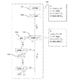
図2は、ホストシステム14と共に、図1における患者監視システム10の1つの監視ユニット24の活動を示す図である。監視ユニット24の動作は、図2の右側に示される。一方、ホストシステム14及びその中央処理ユニット22の動作は、左側に示される。
FIG. 2 is a diagram illustrating the activity of one
図2に示される動作は、ホストシステム14の1つの監視ユニット24から1つのアクセスポイント16、18、20へのデータパッケージAの通信で開始する(ステップ100)。このデータパッケージAは、1つの選択された時間点で送信され、以下の情報を含む。それは、
データパッケージAの通信の時間点の直前に取得された、又は通信の時間点の前により大きな時間期間において集められた生理的状態データPと、
この監視ユニット24のバッテリー残量Lを示すデータと、
このデータパッケージAの通信の時間点を示すタイムスタンプと、
次のデータ通信、即ち次のデータパッケージBの通信の予想される時間点TBとである。
The operation shown in FIG. 2 starts with the communication of the data package A from one
Physiological state data P acquired immediately before the communication time point of data package A or collected in a larger time period before the communication time point;
Data indicating the remaining battery level L of the
A time stamp indicating a communication time point of the data package A;
The following data communication, that is, the time point and the T B the expected communication of the next data package B.
すべてのデータパッケージA、B等は、上記のように同一構造を持つことができる。 All data packages A, B, etc. can have the same structure as described above.
データパッケージAは、アクセスポイント16、18、20に無線で送信され、追加的な解析のため中央処理ユニット22に転送される。中央処理ユニット22は、データパッケージAを受信し(ステップ102)、それを解析する。例えば、データパッケージAが発生する個別の監視ユニット24を着用する患者を参照する生理的状態データPが、重要な状態データの観点から解析される。更に、次のデータ通信の予想される時間点TBが解析される(ステップ104)。
Data package A is transmitted wirelessly to access
ホストシステム14は、時間TBの経過前に何ら追加的なデータパッケージが受信されないことを登録する。データパッケージAを送信した監視ユニット24に対して、ホストシステムは、TBの経過を待つ。時間TBにおいて、次のデータパッケージBが受信されたかが、ホストシステム14によりチェックされる(ステップ106)。このデータパッケージBが、時間TBでアクセスポイント16、18、20に送信されるとき、ステップ102及び104が上述したように実行される。これは、データパッケージBが、重要な生理的状態データP及び別のデータパッケージCの次のデータ通信の予想される時間点Tcに関して解析されることを意味する。Tcも、データパッケージBに含まれる時間関連データの形式において通信される。ホストシステム14は、時間Tcが経過するまで待ち、次のデータパッケージCが到達したかをチェックする、等である。
The
図2は、データパッケージBがこのデータパッケージBの通信の予想された時間点TBにおいて到達しない場合を表す。この場合、ホストシステム14は、データパッケージBが時間TBで受信されなかったことを決定し、個別の通知をユーザに出力する(ステップ108)。この通知は、現在の状態データが個別の監視ユニット24から利用可能でないことを示す。これはまた、個別の監視ユニット24を着用する患者12の識別と、この監視ユニットからの状態データの最後の受信から経過した時間とを示す。この時間通知は、定期的に更新されることができる。
Figure 2 represents the case where data package B does not arrive at the expected time point T B of the communication of the data package B. In this case, the
通知の出力でのTBの経過後(ステップ108)、ホストシステム14は更に、次のデータパッケージBを待つ。通知の時間後別の遅延時間が経過した後、ホストシステムは、アラーム信号を出力する。これは、追加的なデータが個別の監視ユニット24から何ら受信されなかったことを示す。これは、データパッケージBの通信の予想される時間点TBが経過したとき、アラームが直ちに出力されず、しかし、通知が最初に出力され、アラームは、TB後別の時間d1分遅延されることを意味する。その結果、看護スタッフは、監視ユニット24からのデータ通信がより大きな時間期間ないときのみ、アラーム通知を受けることになる。この状態は、監視ユニット24及びホストシステム14の間の接続の中断が原因で現れる可能性がある。患者監視システム10は、次のデータ通信の予想される時間点TBの経過を許容する。なぜなら、患者12が、データ通信が可能でないゾーン32(図1)に実際にいることが通知されるからである。しかしながら、データ通信のない斯かる時間期間が拡張される場合、アラームが出力される(ステップ110)。これは、介入を要求する重篤な状態を示す。
After a T B of the notification of the output (step 108), the
時間遅延d1の長さは、異なる原理に基づきセットされることができる。例えば、時間遅延d1は、所定の長さを持つ固定された時間期間とすることができる。別の可能性は、患者により受信される現在の生理的状態データに基づき時間遅延d1をセットすることである。例えば、患者の生理的状態が悪化する傾向を持つ場合、時間遅延は短縮されることができる。代替的に、時間遅延d1は、生理的状態データを測定する時間間隔に依存する。例えば、選択された生理的パラメータが決定された測定期間内に測定されることになっているとき、時間遅延d1の長さは、1つの測定期間に対応することができる。その結果、ホストシステム14が、アラームを生成する前に別の測定期間を待つ。時間遅延d1は、異なる生理的パラメータに関する異なる測定期間に基づき計算されることもできる。例えば、アラームを生成するための遅延時間d1は、これらの測定期間の最短のもの、これらの測定期間の最長のものに基づかれることができ、又は1つ以上の測定期間に基づき計算されることができる。測定される生理的パラメータに関する1つの例は、1時間の間隔で測定される非侵襲的血圧(NBP)である。一方で、第2の生理的パラメータは、15分おきに測定されるSp02とすることができる。これらの測定期間から、アラームを生成する前に待たれる期間が1つ選択される(即ち、遅延時間d1は、対応して適合される)か、又は、時間d1が両方に基づき計算される。しかしながら、これらの例は、遅延時間d1を計算するための異なる実施形態を表すに過ぎず、より複雑な態様に基づきd1を計算することが可能である。
The length of the time delay d1 can be set based on different principles. For example, the time delay d1 can be a fixed time period having a predetermined length. Another possibility is to set the time delay d1 based on the current physiological state data received by the patient. For example, the time delay can be shortened if the patient's physiological condition tends to deteriorate. Alternatively, the time delay d1 depends on the time interval for measuring physiological state data. For example, when the selected physiological parameter is to be measured within the determined measurement period, the length of the time delay d1 can correspond to one measurement period. As a result, the
時間期間d1の間、ホストシステム14は、次の予想されるデータパッケージが受信されるかどうかをチェックする点を更に理解されたい。これが事実ならば、ホストシステム14は、最近受信されたデータパッケージを解析し、アラームを生成しない。
It should be further understood that during time period d1,
ホストシステム14は、異なる監視ユニット24を処理し、これらの監視ユニット24の現在の状態をその重篤状態に基づき、介入の優先度の順にディスプレイに表示する。例えば、最も長い時間期間データを送信していない監視ユニット24を備える患者は、この順位において最も高いランキングを持つことができる。アラームを生成するとき、段階的拡大機構を提供することも可能である。例えば、ステップ110における第1のアラームが、時間遅延d1後に出力され、一方、より高い強度を持つ第2のアラームが、追加的な時間遅延d2の経過後に出力されることができる。その結果、アラーム信号の強度が、データ通信の予想される時間点TBからの経過時間と共に増加する。第1の時間遅延d1に関して上記されたように、追加的な時間遅延d2の長さは、固定されることができるが、患者の現在の生理的状態に基づき、又は測定される生理的状態データの測定期間に基づき計算されることもできる。同様に、時間期間d2の間、次の予想されたデータパッケージが受信されるかどうかが更に監視され、追加的なアラームを生成する代わりに、ホストシステム14は、最近受信されたデータパッケージを解析する。
The
データパッケージA、B等の解析で、対応する監視ユニット24のバッテリー残量Lが少ないことが分かるとき、アラーム信号が出力される点に留意されたい。
Note that when the analysis of the data packages A, B, etc. reveals that the battery level L of the
無線又は有線接続又はインタフェースを介して、図示されるホストシステム14に接続される外部監視システムに対して、生理的状態データPを含む状態データ及び/又は介入の優先度を示すデータを送信することが可能である。
Sending status data including physiological status data P and / or data indicating priority of intervention to an external monitoring system connected to the
図3において、異なる患者の生理的データを表示するディスプレイが示される。ディスプレイは、左上のフィールドに通知のリストを示す。ここで、右上のフィールドには、チェックされる患者の特定の順位又は解決されるべきアクションを看護スタッフに教えるワークリストが表示される。全体のスクリーンにわたり延在する下部のフィールドには、斯かる監視ユニットを持つすべての患者の位置によりソートされる概要が与えられる。ディスプレイは、位置、アラームの種類、アラームに関する可能な理由、患者の名前、監視ユニットのID、心拍、温度、Sp02、血圧等の複数の生理的データ、接続状態の技術情報及びバッテリー状態を含む。異なる色を用いて、看護スタッフの注意力が増加されることができる。こうして、致命的なアラームは赤で表示されることができる。そして、おそらく点滅する光によりマークされる。この場合、非重篤情報は緑で表示されることができる。こうして、看護スタッフは、すべての患者の概要を常に自分の指揮の下に持つ。これは、患者に対してより高い柔軟性を提供すると共に、患者及び病院に関するセキュリティを増加させる。 In FIG. 3, a display displaying physiological data of different patients is shown. The display shows a list of notifications in the upper left field. Here, in the upper right field, a work list is displayed that tells the nursing staff the specific order of patients to be checked or the action to be resolved. The lower field extending over the entire screen is given a summary sorted by the position of all patients with such a monitoring unit. The display includes location, type of alarm, possible reason for alarm, patient name, monitoring unit ID, heart rate, temperature, Sp02, blood pressure and other physiological data, connection status technical information and battery status. Using different colors, the attention of the nursing staff can be increased. Thus fatal alarms can be displayed in red. And perhaps marked by a flashing light. In this case, the non-severe information can be displayed in green. Thus, the nursing staff always has an overview of all patients under their command. This provides greater flexibility for the patient and increases security for the patient and hospital.
本発明が図面及び前述の説明において詳細に図示され及び説明されたが、斯かる図示及び説明は、説明的又は例示的であると考えられ、本発明を限定するものではない。本発明は、開示された実施形態に限定されるものではない。図面、開示及び添付された請求項の研究から、開示された実施形態に対する他の変形が、請求項に記載の本発明を実施する当業者により理解され、実行されることができる。請求項において、単語「有する」は他の要素又はステップを除外するものではなく、不定冠詞「a」又は「an」は複数性を除外するものではない。特定の手段が相互に異なる従属項に記載されるという単なる事実は、これらの手段の組み合わせが有利に使用されることができないことを意味するものではない。請求項における任意の参照符号は、発明の範囲を限定するものとして解釈されるべきではない。 While the invention has been illustrated and described in detail in the drawings and foregoing description, such illustration and description are to be considered illustrative or exemplary and not restrictive. The invention is not limited to the disclosed embodiments. From studying the drawings, disclosure and appended claims, other variations to the disclosed embodiments can be understood and implemented by those skilled in the art practicing the claimed invention. In the claims, the word “comprising” does not exclude other elements or steps, and the indefinite article “a” or “an” does not exclude a plurality. The mere fact that certain measures are recited in mutually different dependent claims does not indicate that a combination of these measured cannot be used to advantage. Any reference signs in the claims should not be construed as limiting the scope.
Claims (10)
患者の生理的状態を監視する少なくとも1つの監視ユニットと、
前記少なくとも1つの監視ユニットから生理的状態データを無線受信するためのアクセスポイントのネットワークを含むホストシステムとを有し、
前記少なくとも1つの監視ユニットが、この監視ユニットの次のデータ通信の予想される時間点に関する情報を含む時間関連データと共に、選択された時間点での前記生理的状態に関連付けられるデータを前記アクセスポイントの少なくとも1つに送信するよう構成され、
前記ホストシステムが、前記個別の監視ユニットから追加的な生理的状態データの受信なしにデータ通信の予想される時間点の経過後、遅延時間分遅延されるアラーム信号を出力するよう構成され、
前記遅延時間が、前記患者の少なくとも1つの生理的パラメータの少なくとも1つの測定間隔に基づかれる遅延時間、又は、前記患者の現在の生理的状態に基づかれる遅延時間である、
患者監視システム。 A patient monitoring system,
At least one monitoring unit for monitoring the physiological state of the patient;
A host system including a network of access points for wirelessly receiving physiological status data from said at least one monitoring unit;
The at least one monitoring unit transmits data associated with the physiological condition at a selected time point together with time related data including information regarding an expected time point of the next data communication of the monitoring unit. Configured to transmit to at least one of
The host system is configured to output an alarm signal delayed by a delay time after an expected time point of data communication without receiving additional physiological condition data from the individual monitoring unit;
The delay time is a delay time based on at least one measurement interval of at least one physiological parameter of the patient or a delay time based on the current physiological state of the patient;
Patient monitoring system.
前記監視ユニットが、患者の生理的状態データを測定するステップと、
前記監視ユニットが、この監視ユニットの次のデータ通信の予想される時間点に関する情報を含む時間関連データと共に、前記測定された生理的状態データをアクセスポイントに送信するステップと、
前記ホストシステムが、前記個別の監視ユニットから追加的な生理的状態データを受信することなしに、データ通信の予想される時間点の経過後に遅延時間だけ遅延されるアラーム信号を出力するステップであって、前記遅延時間が、前記患者の少なくとも1つの生理的パラメータの少なくとも1つの測定間隔に基づかれる遅延時間、又は、前記患者の現在の生理的状態に基づかれる遅延時間である、出力するステップと、
を有する、方法。 In a method of operating a patient monitoring system having a monitoring unit and a host system ,
Wherein the monitoring unit, and measuring the physiological condition data of a patient,
The monitoring unit transmitting the measured physiological condition data to an access point along with time related data including information regarding an expected time point of the next data communication of the monitoring unit;
The host system outputting an alarm signal that is delayed by a delay time after an expected time point of data communication without receiving additional physiological state data from the individual monitoring unit; The delay time is a delay time based on at least one measurement interval of the at least one physiological parameter of the patient or a delay time based on the current physiological state of the patient; ,
Having a method.
Applications Claiming Priority (3)
| Application Number | Priority Date | Filing Date | Title |
|---|---|---|---|
| EP11150328 | 2011-01-06 | ||
| EP11150328.0 | 2011-01-06 | ||
| PCT/IB2011/055961 WO2012093319A1 (en) | 2011-01-06 | 2011-12-27 | Patient monitoring system and method for monitoring the physiological status of a patient |
Publications (3)
| Publication Number | Publication Date |
|---|---|
| JP2014507974A JP2014507974A (en) | 2014-04-03 |
| JP2014507974A5 JP2014507974A5 (en) | 2015-02-05 |
| JP5991990B2 true JP5991990B2 (en) | 2016-09-14 |
Family
ID=45531485
Family Applications (1)
| Application Number | Title | Priority Date | Filing Date |
|---|---|---|---|
| JP2013547925A Active JP5991990B2 (en) | 2011-01-06 | 2011-12-27 | Patient monitoring system and method for monitoring the physiological state of a patient |
Country Status (7)
| Country | Link |
|---|---|
| US (1) | US9218735B2 (en) |
| EP (1) | EP2661214B1 (en) |
| JP (1) | JP5991990B2 (en) |
| CN (1) | CN103281953B (en) |
| BR (1) | BR112013017162A2 (en) |
| RU (1) | RU2625272C2 (en) |
| WO (1) | WO2012093319A1 (en) |
Families Citing this family (29)
| Publication number | Priority date | Publication date | Assignee | Title |
|---|---|---|---|---|
| US9265429B2 (en) | 2009-09-18 | 2016-02-23 | Welch Allyn, Inc. | Physiological parameter measuring platform device supporting multiple workflows |
| KR101915515B1 (en) | 2010-12-27 | 2018-11-08 | 파인웰 씨오., 엘티디 | Transmitter/receiver unit and receiver unit |
| TWI660618B (en) | 2012-01-20 | 2019-05-21 | 日商精良股份有限公司 | Mobile phone |
| WO2014003160A1 (en) | 2012-06-29 | 2014-01-03 | ローム株式会社 | Stereo earphone |
| US10226200B2 (en) | 2012-04-05 | 2019-03-12 | Welch Allyn, Inc. | User interface enhancements for physiological parameter monitoring platform devices |
| USD772252S1 (en) | 2012-04-05 | 2016-11-22 | Welch Allyn, Inc. | Patient monitoring device with a graphical user interface |
| US9235682B2 (en) * | 2012-04-05 | 2016-01-12 | Welch Allyn, Inc. | Combined episodic and continuous parameter monitoring |
| USD916713S1 (en) | 2012-04-05 | 2021-04-20 | Welch Allyn, Inc. | Display screen with graphical user interface for patient central monitoring station |
| US9055870B2 (en) | 2012-04-05 | 2015-06-16 | Welch Allyn, Inc. | Physiological parameter measuring platform device supporting multiple workflows |
| CA2894583A1 (en) | 2012-12-14 | 2014-06-19 | Koninklijke Philips N.V. | Patient monitoring for sub-acute patients based on activity state and posture |
| JP6186873B2 (en) * | 2013-05-16 | 2017-08-30 | 富士通株式会社 | Monitoring system, outing determination method, and outing determination program |
| JP6186874B2 (en) * | 2013-05-16 | 2017-08-30 | 富士通株式会社 | Monitoring system, monitoring device, monitoring method and monitoring program |
| SG10201402026RA (en) * | 2014-05-04 | 2015-12-30 | Seow Loong Tan | Activity monitoring method and system |
| JP6551919B2 (en) * | 2014-08-20 | 2019-07-31 | 株式会社ファインウェル | Watch system, watch detection device and watch notification device |
| US10728791B2 (en) * | 2014-10-27 | 2020-07-28 | General Electric Company | Wireless interface virtualization |
| CN107111672A (en) * | 2014-11-17 | 2017-08-29 | 埃尔瓦有限公司 | Carry out monitoring treatment compliance using the speech pattern passively captured from patient environmental |
| KR101973486B1 (en) | 2014-12-18 | 2019-04-29 | 파인웰 씨오., 엘티디 | Cartilage conduction hearing device using an electromagnetic vibration unit, and electromagnetic vibration unit |
| FR3034643B1 (en) * | 2015-04-07 | 2021-09-24 | Spineguard | MEDICAL SYSTEM INTENDED TO ENTER ANATOMICAL STRUCTURE OF A PATIENT |
| CN104799839A (en) * | 2015-05-14 | 2015-07-29 | 京东方科技集团股份有限公司 | Monitoring device of blood parameters |
| DE102015108859B4 (en) * | 2015-06-03 | 2018-12-27 | Cortec Gmbh | Method and system for processing data streams |
| KR102056550B1 (en) | 2015-07-15 | 2019-12-16 | 파인웰 씨오., 엘티디 | Robots and Robotic Systems |
| WO2017019929A1 (en) * | 2015-07-29 | 2017-02-02 | Simplifeye, Inc. | System and method for facilitating access to a database |
| JP6551929B2 (en) | 2015-09-16 | 2019-07-31 | 株式会社ファインウェル | Watch with earpiece function |
| EP3393109B1 (en) | 2016-01-19 | 2020-08-05 | FINEWELL Co., Ltd. | Pen-type transceiver device |
| CN109937585B (en) * | 2016-11-11 | 2022-10-18 | 皇家飞利浦有限公司 | Device side testing and reporting for network infrastructure monitoring |
| CN107348942A (en) * | 2017-06-21 | 2017-11-17 | 魏劲萍 | Pressure sore monitoring method and system |
| CN108877914A (en) * | 2018-06-01 | 2018-11-23 | 上海京颐科技股份有限公司 | Behavior monitoring method and device, storage medium, the terminal of patient based on Internet of Things |
| JP2020053948A (en) | 2018-09-28 | 2020-04-02 | 株式会社ファインウェル | Hearing device |
| CN111145844B (en) * | 2019-12-31 | 2023-07-04 | 重庆亚德科技股份有限公司 | Comprehensive medical supervision platform |
Family Cites Families (21)
| Publication number | Priority date | Publication date | Assignee | Title |
|---|---|---|---|---|
| RU2048790C1 (en) * | 1991-06-24 | 1995-11-27 | Всероссийский научно-исследовательский институт автоматики | Device for carrying out distant patient state control |
| US5746203A (en) * | 1996-09-26 | 1998-05-05 | Johnson & Johnson Medical, Inc. | Failsafe supervisor system for a patient monitor |
| GB9719497D0 (en) * | 1997-09-12 | 1997-11-19 | Home Diagnostics Uk Limited | Remote monitoring |
| US5865736A (en) * | 1997-09-30 | 1999-02-02 | Nellcor Puritan Bennett, Inc. | Method and apparatus for nuisance alarm reductions |
| US6175752B1 (en) * | 1998-04-30 | 2001-01-16 | Therasense, Inc. | Analyte monitoring device and methods of use |
| ATE514372T1 (en) | 1998-10-08 | 2011-07-15 | Medtronic Minimed Inc | LICENSE PLATE MONITORING SYSTEM WITH REMOTE MEASUREMENT |
| US7629890B2 (en) * | 2003-12-04 | 2009-12-08 | Hoana Medical, Inc. | System and methods for intelligent medical vigilance with bed exit detection |
| JP2002183849A (en) * | 2000-12-19 | 2002-06-28 | Aiphone Co Ltd | Poriomania person monitoring apparatus |
| RU2200463C2 (en) * | 2001-04-25 | 2003-03-20 | Открытое акционерное общество "Уральский приборостроительный завод" | Device for performing physiological function monitoring |
| JP2004234622A (en) * | 2002-11-19 | 2004-08-19 | Seiko Instruments Inc | Living body information measuring system |
| JP2004230152A (en) * | 2003-01-09 | 2004-08-19 | Seiko Instruments Inc | Biological information measuring system |
| US7311665B2 (en) | 2003-05-19 | 2007-12-25 | Alcohol Monitoring Systems, Inc. | Bio-information sensor monitoring system and method |
| JP2007518470A (en) * | 2003-12-04 | 2007-07-12 | ホアナ メディカル、インコーポレイテッド | Intelligent medical constant monitoring system |
| US7261691B1 (en) * | 2004-08-02 | 2007-08-28 | Kwabena Asomani | Personalized emergency medical monitoring and transmission system |
| US20070253021A1 (en) * | 2006-04-28 | 2007-11-01 | Medtronic Minimed, Inc. | Identification of devices in a medical device network and wireless data communication techniques utilizing device identifiers |
| US8073008B2 (en) | 2006-04-28 | 2011-12-06 | Medtronic Minimed, Inc. | Subnetwork synchronization and variable transmit synchronization techniques for a wireless medical device network |
| CN101422366A (en) | 2007-11-01 | 2009-05-06 | 张海艇 | Respiratory failure monitoring device |
| CN101430817B (en) * | 2007-11-08 | 2011-09-07 | 深圳迈瑞生物医疗电子股份有限公司 | Alarm triggering method and device according to human body rhythmic physiological parameter |
| CN101918990B (en) * | 2008-01-21 | 2013-02-13 | 皇家飞利浦电子股份有限公司 | Controlling an alarm in a medical instrument |
| JP2009211118A (en) * | 2008-02-29 | 2009-09-17 | Konica Minolta Medical & Graphic Inc | Medical image management device, printed image order setting method, and program |
| JP2010171786A (en) * | 2009-01-23 | 2010-08-05 | Yamatake Corp | Failure determination system |
-
2011
- 2011-12-27 JP JP2013547925A patent/JP5991990B2/en active Active
- 2011-12-27 EP EP11813437.8A patent/EP2661214B1/en active Active
- 2011-12-27 CN CN201180064321.2A patent/CN103281953B/en active Active
- 2011-12-27 WO PCT/IB2011/055961 patent/WO2012093319A1/en active Application Filing
- 2011-12-27 RU RU2013136540A patent/RU2625272C2/en active
- 2011-12-27 US US13/977,922 patent/US9218735B2/en active Active
- 2011-12-27 BR BR112013017162A patent/BR112013017162A2/en not_active Application Discontinuation
Also Published As
| Publication number | Publication date |
|---|---|
| RU2013136540A (en) | 2015-02-20 |
| CN103281953B (en) | 2015-12-16 |
| RU2625272C2 (en) | 2017-07-12 |
| US9218735B2 (en) | 2015-12-22 |
| WO2012093319A1 (en) | 2012-07-12 |
| US20130293373A1 (en) | 2013-11-07 |
| CN103281953A (en) | 2013-09-04 |
| BR112013017162A2 (en) | 2016-09-20 |
| JP2014507974A (en) | 2014-04-03 |
| EP2661214B1 (en) | 2017-09-06 |
| EP2661214A1 (en) | 2013-11-13 |
Similar Documents
| Publication | Publication Date | Title |
|---|---|---|
| JP5991990B2 (en) | Patient monitoring system and method for monitoring the physiological state of a patient | |
| US9582646B2 (en) | Connected patient monitoring system and method to provide patient-centric intelligent monitoring services | |
| US9384652B2 (en) | System and method for transfer of primary alarm notification on patient monitoring systems | |
| US8842001B2 (en) | System and method for transfer of primary alarm notification on patient monitoring systems | |
| US8811888B2 (en) | Wireless relay module for monitoring network status | |
| US20150099458A1 (en) | Network-Capable Medical Device for Remote Monitoring Systems | |
| CN104054390B (en) | Wireless relay module with electric power and the medical treatment device closely remote monitoring system of monitoring function | |
| EP3165152B1 (en) | Physiological monitoring system using bluetooth low energy mesh netwok | |
| JP2012254121A (en) | Wireless communication system | |
| WO2017133576A1 (en) | Electric bed | |
| US9905105B1 (en) | Method of increasing sensing device noticeability upon low battery level | |
| JP5877911B2 (en) | Wireless relay module for monitoring network status | |
| GB2568496A (en) | Alarm system | |
| WO2022050899A1 (en) | Patient monitoring device | |
| WO2019089291A1 (en) | Clinical telemetry patient monitoring battery management system and method | |
| JP2004275272A (en) | Biological information terminal, information management apparatus, biological information collection system, method for evaluating irregularity in biological information | |
| HU227955B1 (en) | Method of operating a data processing system as well as a wireless device used for monitoring and continuous controlling vital functions | |
| JP2008194358A (en) | Medical checkup network system, control method and program | |
| JP6644865B2 (en) | Medical systems | |
| CN114554940A (en) | Providing a visual representation of patient monitoring data | |
| KR20200079704A (en) | Safety management system for hospitalized patients in medical institution |
Legal Events
| Date | Code | Title | Description |
|---|---|---|---|
| A521 | Request for written amendment filed |
Free format text: JAPANESE INTERMEDIATE CODE: A523 Effective date: 20141208 |
|
| A621 | Written request for application examination |
Free format text: JAPANESE INTERMEDIATE CODE: A621 Effective date: 20141208 |
|
| A977 | Report on retrieval |
Free format text: JAPANESE INTERMEDIATE CODE: A971007 Effective date: 20150828 |
|
| A131 | Notification of reasons for refusal |
Free format text: JAPANESE INTERMEDIATE CODE: A131 Effective date: 20150901 |
|
| A601 | Written request for extension of time |
Free format text: JAPANESE INTERMEDIATE CODE: A601 Effective date: 20151127 |
|
| A521 | Request for written amendment filed |
Free format text: JAPANESE INTERMEDIATE CODE: A523 Effective date: 20160224 |
|
| TRDD | Decision of grant or rejection written | ||
| A01 | Written decision to grant a patent or to grant a registration (utility model) |
Free format text: JAPANESE INTERMEDIATE CODE: A01 Effective date: 20160721 |
|
| A61 | First payment of annual fees (during grant procedure) |
Free format text: JAPANESE INTERMEDIATE CODE: A61 Effective date: 20160816 |
|
| R150 | Certificate of patent or registration of utility model |
Ref document number: 5991990 Country of ref document: JP Free format text: JAPANESE INTERMEDIATE CODE: R150 |
|
| R250 | Receipt of annual fees |
Free format text: JAPANESE INTERMEDIATE CODE: R250 |
|
| R250 | Receipt of annual fees |
Free format text: JAPANESE INTERMEDIATE CODE: R250 |
|
| R250 | Receipt of annual fees |
Free format text: JAPANESE INTERMEDIATE CODE: R250 |
|
| R250 | Receipt of annual fees |
Free format text: JAPANESE INTERMEDIATE CODE: R250 |
|
| R250 | Receipt of annual fees |
Free format text: JAPANESE INTERMEDIATE CODE: R250 |