JP5984596B2 - Sockets and lighting fixtures - Google Patents
Sockets and lighting fixtures Download PDFInfo
- Publication number
- JP5984596B2 JP5984596B2 JP2012205111A JP2012205111A JP5984596B2 JP 5984596 B2 JP5984596 B2 JP 5984596B2 JP 2012205111 A JP2012205111 A JP 2012205111A JP 2012205111 A JP2012205111 A JP 2012205111A JP 5984596 B2 JP5984596 B2 JP 5984596B2
- Authority
- JP
- Japan
- Prior art keywords
- holding
- socket
- straight tube
- lamp
- pin
- Prior art date
- Legal status (The legal status is an assumption and is not a legal conclusion. Google has not performed a legal analysis and makes no representation as to the accuracy of the status listed.)
- Active
Links
Images


Description
本発明は、直管ランプの口金を装着するソケット、及びこのソケットを備えた照明器具に関する。 The present invention relates to a socket to which a base of a straight tube lamp is attached, and a lighting fixture provided with the socket.
従来、直管蛍光ランプを装着できるランプソケットは、直管蛍光ランプのランプピンを電気的に接続する役割、充電部との感電を防止する役割、及び直管蛍光ランプの落下を抑えるための機械的保持の役割を担っていた(例えば、特許文献1参照)。 Conventionally, a lamp socket to which a straight tube fluorescent lamp can be mounted has a role of electrically connecting a lamp pin of the straight tube fluorescent lamp, a role of preventing an electric shock with a charged part, and a mechanical for suppressing a fall of the straight tube fluorescent lamp. It played a role of holding (see, for example, Patent Document 1).
上述したランプソケットの役割を達成するため、ランプソケットは特許文献1の図1のように、多くの樹脂成形品と導電金具とで構成されている。このため、従来のランプソケットは、部材コストが高くなるとともに、組み立て費用も発生するという課題がある。 In order to achieve the role of the lamp socket described above, the lamp socket is composed of many resin molded products and conductive metal fittings as shown in FIG. For this reason, the conventional lamp socket has the subject that a member cost becomes high and an assembly cost also arises.
昨今、直管蛍光ランプの代替として直管LEDランプが多く販売されている。直管LEDランプの口金には、JIS C 7709で公知のGX16t−5口金、あるいは、従来の直管蛍光ランプと同じG13口金等が使用されている。これらの直管LEDランプは、片口金通電方式の接続方法をとるものである。片口金通電方式の直管LEDランプは、一端側に給電のための給電側口金を備え、他端側に保持のための保持側口金を備えている。 Recently, many straight tube LED lamps are sold as an alternative to the straight tube fluorescent lamp. As the base of the straight tube LED lamp, a GX16t-5 base known in JIS C 7709 or the same G13 base as a conventional straight tube fluorescent lamp is used. These straight tube LED lamps take a single-electrode energization connection method. The single-tube energization type straight tube LED lamp has a power supply side base for power supply on one end side and a holding side base for holding on the other end side.
片口金通電方式の直管LEDランプの保持側口金を装着するソケットは、保持側口金の保持ピンを保持することが要求される。従来の保持用のソケットでは、必要以上の機能を備えているため、部品数が多くなり部材コストが高くなるとともに、組立てにも費用が発生するという課題がある。 The socket to which the holding side cap of the straight tube LED lamp of the single cap energization method is required to hold the holding pin of the holding side cap. Since the conventional holding socket has more functions than necessary, there are problems that the number of parts is increased, the member cost is increased, and the assembly is also expensive.
本発明に係るソケットは、上記のような課題を解決するためになされたものであり、保持側ソケットの構成部品数を減らすことができ、組立工数も削除し、コストダウンを図ることを目的としている。 The socket according to the present invention is made in order to solve the above-mentioned problems, and can reduce the number of components of the holding-side socket, delete the number of assembly steps, and reduce the cost. Yes.
本発明に係るソケットは、一端部に保持のための保持ピンを備える直管ランプを装着するソケットにおいて、前面板部と、前記前面板部に対向する後面板部と、前記前面板部の上部と前記後面板部の上部とをつなぐ上面板部と、前記前面板部における前記上面板部よりも下方の位置から上方に向かって前記上面板部まで、前記前面板部が前記後面板部側に凹むことにより形成された溝部と、前記上面板部の前記溝部の凹み形状に対応する部分が開口することにより形成された上面開口部と、前記上面開口部から前記溝部に前記直管ランプの前記保持ピンが挿入されると、前記保持ピンを保持する保持部とを備え、一体成形されたことを特徴とする。 The socket according to the present invention is a socket for mounting a straight tube lamp having a holding pin for holding at one end, a front plate portion, a rear plate portion facing the front plate portion, and an upper portion of the front plate portion. And an upper surface plate portion connecting the upper portion of the rear surface plate portion and a position lower than the upper surface plate portion in the front surface plate portion to the upper surface plate portion upward, and the front surface plate portion is on the rear surface plate portion side. A groove portion formed by recessing, an upper surface opening portion formed by opening a portion corresponding to the recess shape of the groove portion of the upper surface plate portion, and the straight tube lamp from the upper surface opening portion to the groove portion. When the holding pin is inserted, a holding portion that holds the holding pin is provided and is integrally formed.
本発明に係るソケットは、一端部に保持のための保持ピンを備える直管ランプを装着するソケットにおいて、前面板部と、前記前面板部に対向する後面板部と、前記前面板部の上部と前記後面板部の上部とをつなぐ上面板部と、前記前面板部における前記上面板部よりも下方の位置から上方に向かって前記上面板部まで、前記前面板部が前記後面板部側に凹むことにより形成された溝部と、前記上面板部の前記溝部の凹み形状に対応する部分が開口することにより形成された上面開口部と、前記上面開口部から前記溝部に前記直管ランプの前記保持ピンが挿入されると、前記保持ピンを保持する保持部とを備え、一体成形されているので、構成部品数を減らすとともに、組立工数も削除することができ、コストダウンを図ることができるという効果を奏する。 The socket according to the present invention is a socket for mounting a straight tube lamp having a holding pin for holding at one end, a front plate portion, a rear plate portion facing the front plate portion, and an upper portion of the front plate portion. And an upper surface plate portion connecting the upper portion of the rear surface plate portion and a position lower than the upper surface plate portion in the front surface plate portion to the upper surface plate portion upward, and the front surface plate portion is on the rear surface plate portion side. A groove portion formed by recessing, an upper surface opening portion formed by opening a portion corresponding to the recess shape of the groove portion of the upper surface plate portion, and the straight tube lamp from the upper surface opening portion to the groove portion. When the holding pin is inserted, it is provided with a holding portion that holds the holding pin, and is integrally molded, so that the number of components can be reduced and the number of assembly steps can be eliminated, thereby reducing the cost. I can An effect.
以下の実施の形態について、図を用いて説明する。なお、以下の実施の形態の説明において、「上」、「下」、「左」、「右」、「前」、「後」、「表」、「裏」といった方向は、説明の便宜上、そのように記しているだけであって、装置、器具、部品等の配置や向き等を限定するものではない。 The following embodiments will be described with reference to the drawings. In the following description of the embodiments, directions such as “up”, “down”, “left”, “right”, “front”, “back”, “front”, “back” are for convenience of explanation. It is only described as such, and does not limit the arrangement or orientation of devices, instruments, parts, and the like.
実施の形態1. Embodiment 1 FIG.
図1は、本実施の形態に係る照明器具1の斜視図である。図2は、直管LEDランプの一例を示したものであり、(a)は片側の口金のみ給電するGX16t−5口金の直管LEDランプ10、(b)は片側の口金のみ給電するG13口金の直管LEDランプ10’を示す図である。
図1及び図2を用いて、本実施の形態に係る照明器具1及び直管LEDランプ10,10’の全体構成について説明する。
FIG. 1 is a perspective view of a lighting fixture 1 according to the present embodiment. FIG. 2 shows an example of a straight tube LED lamp. (A) is a straight
The whole structure of the lighting fixture 1 and straight tube |
図1に示すように、照明器具1は、器具本体2と、反射板3とを備える。照明器具1は、器具本体2の長手方向の一端側に給電側ソケット4を備え、他端側に保持側ソケット20を備え、直管LEDランプ10を装着することができる。照明器具1は、器具本体2に取り付けられ、給電側ソケット4及び保持側ソケット20に装着された直管LEDランプ10を点灯させる点灯装置(図示せず)を備える。反射板3は、直管LEDランプ10から発せられる光を配光する機能を有する。
As shown in FIG. 1, the lighting fixture 1 includes a
図2(a)(b)に示すように、直管LEDランプ10は、外郭17、給電側口金11、保持側口金13を備える。直管LEDランプ10’は、外郭17’、給電側口金11’、保持側口金13’を備える。外郭17,17’は、ガラスや樹脂で成形され、一端側に給電側口金11,11’が取り付けられ、他端側に保持側口金13,13’が取り付けられる。
As shown in FIGS. 2A and 2B, the straight
図2(a)に示すように、給電側口金11は、一対のL字型形状の給電ピン12を備える。給電ピン12は、外郭17の内部にあるLED素子15と電線16で接続されている。LED素子15は、直列に接続されているが、並列などに接続されていてもよい。また、図示しないダイオードブリッジを給電ピン12とLED素子15間に配設することで、給電ピン12を無極性としてもよい。給電側口金11は、給電側ソケット4(図1参照)に取り付けられる。
As shown in FIG. 2A, the
図2(a)に示すように、保持側口金13は、T字型形状の保持ピン14を備える。保持ピン14の先端部は、楕円形状(図4(c)参照)の平板状の突出部14aが設けられている。保持ピン14は、どこにも接続されていない。保持ピン14は、保持側ソケット20(図1参照)に取り付けられ、直管LEDランプ10を保持する役割を有する。
As shown in FIG. 2A, the
図2(b)に示すように、給電側口金11’は、一対の給電ピン12’を備える。給電ピン12’は、外郭17’の内部にあるLED素子15’と電線16’で接続されている。LED素子15’は、直列に接続されているが、並列などに接続されていてもよい。また、図示しないダイオードブリッジを給電ピン12’とLED素子15’間に配設することで、給電ピン12’を無極性としてもよい。
As shown in FIG. 2B, the power supply side cap 11 'includes a pair of power supply pins 12'. The power feed pin 12 'is connected to the LED element 15' inside the outer shell 17 'by an electric wire 16'. The LED elements 15 'are connected in series, but may be connected in parallel. Further, a
図2(b)に示すように、保持側口金13’は、給電ピン12’と同形状の一対の保持ピン14’を備える。保持ピン14’は、どこにも接続されていない。保持ピン14’は、後述する保持側ソケット40(図5参照)に取り付けられ、直管LEDランプ10’を保持する役割を有する。
As shown in FIG. 2B, the holding-side base 13 'includes a pair of holding pins 14' having the same shape as the power supply pin 12 '. The holding pin 14 'is not connected anywhere. The holding
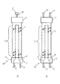
図3は、(a)は直管LEDランプ10を装着するソケットの一例(GX16t−5受金保持側ソケット60)であり、(b)は直管LEDランプ10’を装着するソケット(G13受金蛍光灯ソケット70)の一例である。
FIG. 3A is an example of a socket (GX16t-5 receiving-holding side socket 60) in which the straight
GX16t−5受金保持側ソケット60は、直管LEDランプ10のGX16t−5口金である保持側口金13(図2(a)参照)を装着できるソケットである。図3(a)に示すように、GX16t−5受金保持側ソケット60は、本体61とカバー63と一対の導電金具62とにより構成される。本体61とカバー63で形成された略箱体の内部にある導電金具62で保持側口金13の保持ピン14を挟持し、保持側口金13を保持する。
The GX16t-5 gold-holding
G13受金蛍光灯ソケット70は、直管LEDランプ10’のG13口金である保持側口金13’(図2(b)参照)を装着できるソケットである。図6(b)に示すように、G13受金蛍光灯ソケット70は、直管蛍光ランプ用のソケットを流用したものである。G13受金蛍光灯ソケット70は、本体71とカバー74と回転子72と一対の導電金具73とにより構成される。本体71とカバー74で形成された略箱体の内部には、回転子72と一対の導電金具73とが配設される。回転子72も形成された溝部分に一対の保持ピン14’が挿入され、回転子72が回転することにより溝部分に挿入された一対の保持ピン14’が一対の導電金具73により挟持され、保持側口金13’が保持される。
The G13 light receiving
片口金通電方式の直管LEDランプ10,10’の場合、ソケットには、直管LEDランプ10(または直管LEDランプ10’)の保持ピン14(または一対の保持ピン14’)を保持することが要求される。しかし、図3(a)(b)に示すようなソケット(GX16t−5受金保持側ソケット60、または、G13受金蛍光灯ソケット70)では、必要以上の機能を備えているため、部品数が多くなり部材コストが高くなる上、組立てにも費用が発生する。
In the case of the straight
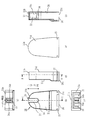
図4は、本実施の形態に係る保持側ソケット20を示す図であり、(a)は平面図、(b)は正面図、(c)は底面図、(d)は側面図、(e)は背面図である。図5は、本実施の形態の保持側ソケット20を示す図であり、(a)は正面断面図(A−A断面図)、(b)は正面側から見た底面斜視図、(c)は背面側(後面側)から見た底面斜視図である。なお、図4(d)は、右側面図であるが、左側面図も同一形状である。
4A and 4B are diagrams showing the holding-
図4及び図5を用いて、本実施の形態に係る保持側ソケット20の全体構成について説明する。
The overall configuration of the holding-
保持側ソケット20は、図2(a)において説明した直管LEDランプ10を装着するソケットであり、直管LEDランプ10の保持のための保持ピン14を保持する機能を有するソケットである。
The holding-
保持側ソケット20は、前面21a(前面板部)と、前面に対向する後面21d(後面板部)と、前面21aの上部と後面21dの上部とをつなぐ上面21bと、両側の側面21eとを備える。保持側ソケット20は、上面21bが突き出すように湾曲したかまぼこ形状、ドーム形状である。
The holding-
保持側ソケット20は、前面21aにおいて上面21bよりも下方の位置から上方に向かって上面21bまで、前面21aが後面21d側に凹むことにより形成されたランプ保持部22(溝部)を備える。
また、保持側ソケット20は、上面21bのランプ保持部22(溝部)の凹み形状に対応する部分が開口することにより形成されたピン挿入孔23(上面開口部)を備える。
また、保持側ソケット20は、ピン挿入孔23からランプ保持部22に直管LEDランプ10の保持ピン14が挿入されると、その保持ピン14を保持するランプ係止部24(保持部)を備える。
ランプ係止部24は、ランプ保持部22の凹み形状の表面に、保持ピン14を保持するための突起部24a,24a’,24b,24b’を備える。
The holding-
The holding-
In addition, when the holding
The
保持側ソケット20は、熱可塑性樹脂の絶縁材、例えば、ポリカーボネイドやポリブチレンテレフタレートなどにより形成されている。保持側ソケット20は、金型等を用いて一体形成されている。
The holding-
図4(c)、図5(b)(c)に示すように、保持側ソケット20の底面21cには、底面21cの略全面が開口した全面開口部26が形成される。保持側ソケット20の内部は空間28となっている。
As shown in FIGS. 4C, 5B, and 5C, the
図4(b)(d)(e)に示すように、保持側ソケット20の両側の側面21eの下方には、器具本体2に取り付けるための本体取付部27が形成されている。保持側ソケット20は、両側の側面21eに溝形状の本体取付部27を備える。溝形状の本体取付部27は、器具本体2に形成されるソケットを取り付けるための取付孔の周縁(図示無し)に嵌め合わされることにより、保持側ソケット20が器具本体2に取り付けられる。
As shown in FIGS. 4B, 4 </ b> D, and 4 </ b> E, a
次に、保持側ソケット20の構成及び機能について説明する。
ランプ保持部22は、前面21aの中央部のやや上方から上面21bまで切り欠かれて形成された凹部である。図4(a)に示すように、上面21bにはランプ保持部22に連通するピン挿入孔23が形成される。
Next, the configuration and function of the holding
The
図4(b)において、保持ピン14の端面を一点鎖線で示す。保持ピン14の楕円の先端部は、長径L1を上下方向に沿わせてピン挿入孔23からランプ保持部22に挿入される。ピン挿入孔23部分の幅は、ランプ保持部22の幅よりもやや広く形成されている。これにより、ピン挿入孔23へ保持ピン14を挿入しやすくなる。ランプ保持部22の下方の端部に保持ピン14が係止される。ランプ保持部22の下方の端部の保持ピン14が係止される箇所をランプ係止部24とする。
In FIG.4 (b), the end surface of the holding
保持ピン14の楕円の先端部は、ランプ係止部24に到達すると、90度回転される。これにより、保持ピン14の楕円の先端部は短径L2が上下方向に沿うようにランプ係止部24に配置される。ランプ係止部24は、保持ピン14の楕円形状が回転できる大きさに形成されている。
When the elliptical tip of the holding
上述したように、直管LEDランプ10の保持ピン14は、ピン挿入孔23を通過し、ランプ保持部22のランプ係止部24にて、直管LEDランプ10を90°回転させて保持される。ランプ係止部24には、複数の突起部24a,24a’,24b,24b’が形成されている。直管LEDランプ10の回転動作時に突起部24a,24a’,24b,24b’を保持ピン14の先端部が乗り越えることで、直管LEDランプ10の装着感を得ることができる。
As described above, the holding
また、突起部24aと突起部24a’との間の部位24c、及び、突起部24bと突起部24b’との間の部位24dにて保持ピン14を保持するので、直管LEDランプ10が落下することはない。
Further, since the holding
底面21cは開放され、樹脂成形時の金型の通り道となる。図5(a)に示すように、保持側ソケット20の内部の空間28は、樹脂成型時には金型が嵌る部分である。図5(a)に示すように、保持側ソケット20は、金型を簡単に外すことができるように設計されている。
The
つまり、保持側ソケット20は、1つの樹脂成形品で構成されている。金型を外すために底面21cは全面開口部26となっているが、器具本体2に取り付けられた場合、保持側ソケット20の底面21c側は視認できない。このため、図3(a)のGX16t−5受金保持側ソケット60や図3(b)のG13受金蛍光灯ソケット70と同等の意匠を得ることができる。
That is, the holding
以上のように、本実施の形態に係る保持側ソケット20は、器具本体と、LEDを備え、一端部に給電を目的とした給電側口金を有するとともに、他端部に保持を目的とした保持側口金を有する直管LEDランプと、器具本体に取り付けられ、直管LEDランプの給電側口金を装着できる給電側ソケットと、器具本体に取り付けられ、直管LEDランプの保持側口金を装着できる保持側ソケットとを備える。保持側ソケットは、1つの樹脂成形品で構成されているので、保持側ソケットの構成部品数を減らすことができ、組立工数も削除し、コストダウンを図ることができる。
As described above, the holding-
また、本実施の形態に係る保持側ソケットは、前面にランプ保持部を有し、ランプ保持部の外周の一部と上面まで連通したピン挿入孔を備え、保持側ソケットの底面は開放されているので、1つの樹脂成形品として構成するための生産方法が容易となり、組立工数も削除し、コストダウンを図ることができる。 In addition, the holding side socket according to the present embodiment has a lamp holding portion on the front surface, includes a pin insertion hole that communicates with a part of the outer periphery of the lamp holding portion to the top surface, and the bottom surface of the holding side socket is open. Therefore, the production method for constituting a single resin molded product is facilitated, the number of assembly steps can be eliminated, and the cost can be reduced.
また、本実施の形態に係る保持側ソケットは、保持側ソケットのランプ保持部のランプ係止部に複数の突起部を有し、保持側口金の保持ピンを突起部で固定するので、簡単な構成で確実に保持ピンを保持することができる。 Further, the holding-side socket according to the present embodiment has a plurality of protrusions on the lamp engaging portion of the lamp holding portion of the holding-side socket, and the holding pins of the holding-side base are fixed by the protrusions. With the configuration, the holding pin can be securely held.
実施の形態2.
本実施の形態では、実施の形態1と異なる構成の保持側ソケット30について説明する。
図6は、本実施の形態に係る保持側ソケット30を示す図であり、(a)は平面図、(b)は正面図、(c)は底面図、(d)は側面図、(e)は背面図、(f)は側面断面図(C−C断面図)である。図7は、本実施の形態の保持側ソケット30を示す図であり、(a)は正面断面図(B−B断面図)、(b)は正面側から見た上面斜視図、(c)は背面側(後面側)から見た上面斜視図である。なお、図6(d)は、右側面図であるが、左側面図も同一形状である。
In the present embodiment, a holding-
6A and 6B are diagrams showing the holding-
図6及び図7は、実施の形態1で説明した図4及び図5に対応する図であり、同様の機能を有する構成部には同一の符号を付し、その説明を省略する場合がある。
図6及び図7を用いて、本実施の形態に係る保持側ソケット30の全体構成について説明する。
FIGS. 6 and 7 are diagrams corresponding to FIGS. 4 and 5 described in the first embodiment. Components having similar functions are denoted by the same reference numerals, and description thereof may be omitted. .
The overall configuration of the holding-
本実施の形態に係る保持側ソケット30において、実施の形態1に係る保持側ソケット20と異なる点は、ランプ保持部22のランプ係止部34の構成である。
The holding-
図7(a)に示すように、保持側ソケット30は、溝部であるランプ保持部22の凹み形状を形成する一対の爪部34a,34bを備える。ランプ係止部34は、一対の爪部34a,34bにより構成される。保持側ソケット30は、ランプ保持部22に保持ピン14が挿入されると、保持ピン14を一対の爪部34a,34bの弾性力により保持する。
As shown in FIG. 7A, the holding-
一対の爪部34a,34bは、図6(a)に示すように、上面21bのピン挿入孔23の対向する一対の周縁から連続して各々下方に向かって形成される。図7(a)(b)に示すように、一対の爪部34a,34bは、ランプ保持部22の凹み形状の内壁を形成している。ただし、爪部34a,34bの各々は、ピン挿入孔23の周縁から底面21c方向に延設された片もち梁形状に形成される。
As shown in FIG. 6A, the pair of
保持側ソケット30は、前面21aに凹み形状のランプ保持部22を有し、ランプ保持部22の外周の一部と上面21bにおいて連通したピン挿入孔23を備える。また、保持側ソケット30の内部には、上面21bから下方に延びる一対の爪部34a,34bを備える。
The holding-
図7(a)に示すように、直管LEDランプ10の保持ピン14は、ピン挿入孔23を通過し、ランプ保持部22の下方の端部であるランプ係止部34にて、直管LEDランプ10を90°回転させることにより、先端部の短径L2が上下方向に沿うようにランプ係止部34に配置される。つまり、保持ピン14の楕円の先端部は、横長にランプ係止部34に配置される。このとき、保持ピン14の楕円の先端部の長径L1は、ランプ保持部22の幅よりも長くなるように設計されている。したがって、保持ピン14の楕円の先端部は、一対の爪部34a,34bが間隔を維持しようとする弾性力により挟持される。これにより、保持ピン14は、保持され、直管LEDランプ10が落下することはない。
As shown in FIG. 7A, the holding
本実施の形態に係る保持側ソケット30も実施の形態1で説明した保持側ソケット20と同様に、底面21cは開放され、樹脂成形時の金型の通り道となる。図7(a)に示すように、保持側ソケット30の内部の空間28は、樹脂成型時には金型が嵌る部分である。図7(a)に示すように、保持側ソケット30は、金型を簡単に外すことができるように設計されている。
Similarly to the holding-
つまり、保持側ソケット30は、1つの樹脂成形品で構成されている。金型を外すために底面21cには全面開口部26となっているが、器具本体2に取り付けられた場合、保持側ソケット20の底面21cは視認できない。このため、保持側ソケット30は、図3(a)のGX16t−5受金保持側ソケット60や図3(b)のG13受金蛍光灯ソケット70と同等の意匠を得ることができる。
That is, the holding
本実施の形態に係る保持側ソケット30は、ランプ保持部22の凹み形状の内壁となっている一対の爪部34a,34bを備え、保持ピン14を一対の爪部34a,34bの弾性力により保持するので、簡単な構成により確実に保持ピン14を保持することができる。
The holding-
実施の形態3.
図8は、本実施の形態に係る保持側ソケット40の分解斜視図である。図9は、本実施の形態に係る保持側ソケット40を示す図であり、(a)は底面斜視図、(b)回転子の断面図(D−D断面図)である。
Embodiment 3 FIG.
FIG. 8 is an exploded perspective view of the holding-
図8及び図9を用いて、本実施の形態に係る保持側ソケット40の全体構成について説明する。
The overall configuration of the holding-
保持側ソケット40は、図2(b)において説明した直管LEDランプ10’を装着するソケットであり、保持のための一対の保持ピン14’(図2(b)参照)を保持する機能を有するソケットである。
The holding-
保持側ソケット40は、ソケット本体41と、回転子50とを備える。
ソケット本体41は、前面41a(前面板部)と、前面41aに対向する後面41d(後面板部)と、前面41aの上部と後面41dの上部とをつなぐ上面41b(上面板部)と、前面41aに設けられた円形の前面開口部42とを備える。前面開口部42は、上面41bに形成されたピン挿入孔43と連通している。
The holding-
The
回転子50は、一対の保持ピン14’を挿入する切り欠け部53(回転子溝部)を備えた円筒形の回転子であって、ソケット本体41の前面開口部42に挿入され回転することにより一対の保持ピン14’を保持する。
The
ソケット本体41は、一体成形されている。また、回転子50も一体形成されている。つまり、保持側ソケット40は、一体形成されている2部品(ソケット本体41及び回転子50)から構成されている。
The
保持側ソケット40のソケット本体41及び回転子50は、熱可塑性樹脂の絶縁材、例えば、ポリカーボネイドやポリブチレンテレフタレートなどで形成される。
The
回転子50は、前面開口部42より小さい径の略円板状の受部51を備える。また、回転子50は、受部51の裏面側(配置された場合の後面41d側)に、前面開口部42より大きい径の略円板状の止め部52を備える。また、回転子50は、止め部52の裏面から立設する円筒部54を備える。回転子50は、略円筒形である。
The
回転子50には、受部51から円筒部54の途中まで、回転子50を二分するように切り欠かれた切り欠け部53(回転子溝部)を備える。切り欠け部53は、一対の保持ピン14’が挿入される。切り欠け部53の幅は、保持ピン14’の径と略同一、あるいはやや広く形成される。また、切り欠け部53の長さは、一対の保持ピン14’の幅と略同一、あるいは一対の保持ピン14’の幅よりやや長く形成される。
The
回転子50は、円筒部54の受部51側の反対側の端部の外周に、複数の凸部55を備える。例えば、凸部55は、円筒部54の外周の互いに対向する位置に2つ設けられる。
The
ソケット本体41は、前面開口部42に挿入された回転子50の円筒部54を、保持及び円滑に回転動作させるためのガイド部44を備える。ガイド部44は、後面41dの内側面から、ソケット本体41の内部に向かって円筒部54の外周に沿うように円形、環形に突き出している。また、ガイド部44には、ガイド部44の環状形状を四分する4つの凹部45が形成されている。
The
図9(a)に示すように、回転子50の凸部55が、ガイド部44の凹部45に嵌る。このように、凸部55と凹部45とが嵌め合わされることで、直管LEDランプ10’の装着感を得ることができる。切り欠け部53が上下方向に沿う状態に回転子50が配置されると、上下方向の2つの凹部45に回転子50の2つの凸部55が嵌って係止される。また、その状態から回転子50が90°回転することで、切り欠け部53が上下方向に直交する状態に回転子50が配置されると、上下方向に直交して対向する2つの凹部45に、回転子50の凸部55が嵌って係止される。
As shown in FIG. 9A, the
一対の保持ピン14’は、切り欠け部53が上下方向に沿った位置で、ピン挿入孔43から切り欠け部53に挿入される。直管LEDランプ10’を90°回転することで、回転子50の切り欠け部53は上下方向に垂直な方向に(水平方向)に沿った位置となり、凸部55と凹部45とが嵌め合わされる。このとき、切り欠け部53の両端部は前面開口部42の周縁で塞がれ、一対の保持ピン14’は回転子50の切り欠け部53で保持される。このため、直管LEDランプ10’が落下することはない。
The pair of holding
また、回転子50の組立ては、回転子50をソケット本体41の前面41aの前面開口部42から押し込み、止め部52が前面開口部42の周縁の内側に引っ掛かることで抜けることはない。
The
底面41cには、底面41cが開放された全面開口部46が形成される。全面開口部46は、実施の形態1〜2において説明した全面開口部26と同様の構成部であり、樹脂成形時の金型の通り道である。つまり保持側ソケット40は、ソケット本体41と回転子50との2つの樹脂成形品で構成されている。また、保持側ソケット40が器具本体2に取り付けられた場合、保持側ソケット40の底面41cは視認できないため、図3(a)のGX16t−5受金保持側ソケット60や図3(b)のG13受金蛍光灯ソケット70と同等の意匠を得ることができる。
The
以上のように、実施の形態1〜3に係る照明器具は、器具本体と、LEDを備え、一端部に給電を目的とした給電側口金を有するとともに、他端部に保持を目的とした保持側口金を有する直管LEDランプと、器具本体に取り付けられ、直管LEDランプの給電側口金を装着できる給電側ソケットと、器具本体に取り付けられ、直管LEDランプの保持側口金を装着できる保持側ソケットとを備え、保持側ソケットは、1つ又は二つの樹脂成形品で構成されている。 As described above, the lighting fixtures according to the first to third embodiments include a fixture main body and an LED, and have a power supply side base for power supply at one end and a holding for the other end. A straight tube LED lamp having a side cap, a power supply side socket that can be mounted on the power supply side cap of the straight tube LED lamp, and a holder that can be mounted on the fixture main body and can be mounted on the holding side cap of the straight tube LED lamp The holding socket is configured by one or two resin molded products.
したがって、実施の形態1〜3に係る保持側ソケット40によれば、意匠を変えることなく、保持側ソケット40の構成部品数を減らすことができ、組立工数も削除し、コストダウンを図ることができる。
Therefore, according to the holding |
以上、本発明の実施の形態について説明したが、これらの実施の形態の2つを組み合わせて実施しても構わない。あるいは、これらの実施の形態のうち、1つを部分的に実施しても構わない。あるいは、これらの実施の形態のうち、2つ以上を部分的に組み合わせて実施しても構わない。なお、本発明は、これらの実施の形態に限定されるものではなく、必要に応じて種々の変更が可能である。 As mentioned above, although embodiment of this invention was described, you may implement combining two of these embodiment. Alternatively, one of these embodiments may be partially implemented. Alternatively, two or more of these embodiments may be partially combined. In addition, this invention is not limited to these embodiment, A various change is possible as needed.
1 照明器具、2 器具本体、3 反射板、4 給電側ソケット、10 直管LEDランプ、11 給電側口金、12 給電ピン、13 保持側口金、14 保持ピン、15 LED素子、16 電線、17 外郭、20 保持側ソケット、21a 前面、21b 上面、21c 底面、21d 後面、21e 側面、22 ランプ保持部、23 ピン挿入孔、24 ランプ係止部、24a,24b 突起部、24c,24d 部位、26 全面開口部、27 本体取付部、28 空間、30 保持側ソケット、34 ランプ係止部、34a,34b 爪部、40 保持側ソケット、41 ソケット本体、41a 前面、41b 上面、41c 底面、41d 後面、42 前面開口部、43 ピン挿入孔、44 ガイド部、45 凹部、46 全面開口部、50 回転子、51 受部、52 止め部、53 切り欠け部、54 円筒部、55 凸部、60 GX16t−5受金保持側ソケット、61 本体、62 導電金具、63 カバー、70 G13受金蛍光灯ソケット、71 本体、72 回転子、73 導電金具、74 カバー。
DESCRIPTION OF SYMBOLS 1 Lighting fixture, 2 Appliance main body, 3 Reflecting plate, 4 Power supply side socket, 10 Straight tube LED lamp, 11 Power supply side cap, 12 Power supply pin, 13 Holding side cap, 14 Holding pin, 15 LED element, 16 Electric wire, 17 Outer , 20 Holding side socket, 21a Front surface, 21b Top surface, 21c Bottom surface, 21d Rear surface, 21e Side surface, 22 Lamp holding portion, 23 Pin insertion hole, 24 Lamp locking portion, 24a, 24b Projection portion, 24c, 24d Site, 26 Entire surface Opening portion, 27 body mounting portion, 28 space, 30 holding side socket, 34 lamp locking portion, 34a, 34b claw portion, 40 holding side socket, 41 socket body, 41a front surface, 41b top surface, 41c bottom surface, 41d rear surface, 42 Front opening, 43 Pin insertion hole, 44 Guide, 45 Recess, 46 Full opening, 50
Claims (6)
前面板部と、
前記前面板部に対向する後面板部と、
前記前面板部に形成され、前記前面板部が前記後面板部の側に凹むことにより形成された凹み形状である溝部と、
前記溝部に挿入された前記保持ピンが回転されると、前記保持ピンの前記突出部を保持する保持部と
を備え、
前記前面板部と前記後面板部と前記溝部と前記保持部とは、一体成形されたソケット。 In a socket to which a straight tube lamp equipped with a holding pin having a protruding portion at the tip end is attached,
The front plate,
A rear plate facing the front plate,
A groove portion that is formed in the front plate portion, and is a concave shape formed by the front plate portion being recessed toward the rear plate portion;
When the holding pin inserted into the groove portion is rotated , the holding pin holds the protruding portion of the holding pin,
The front plate portion, the rear plate portion, the groove portion, and the holding portion are integrally formed sockets.
前面板部と、 The front plate,
前記前面板部に対向する後面板部と、 A rear plate facing the front plate,
前記前面板部に形成され、前記前面板部が前記後面板部の側に凹むことにより形成された凹み形状である溝部と、 A groove portion that is formed in the front plate portion, and is a concave shape formed by the front plate portion being recessed toward the rear plate portion;
前記溝部に前記直管ランプの前記保持ピンが挿入されると、前記保持ピンを保持する保持部と When the holding pin of the straight tube lamp is inserted into the groove portion, a holding portion that holds the holding pin;
を備え、With
前記前面板部と前記後面板部と前記溝部と前記保持部とは、一体成形されており、 The front plate portion, the rear plate portion, the groove portion, and the holding portion are integrally formed,
前記保持部は、 The holding part is
前記溝部の凹み形状を形成している一対の爪部を備え、前記溝部に前記保持ピンが挿入されると、前記保持ピンを前記一対の爪部の弾性力により保持するソケット。 A socket comprising a pair of claw portions forming a concave shape of the groove portion, and holding the holding pin by an elastic force of the pair of claw portions when the holding pin is inserted into the groove portion.
前記前面板部の上部と前記後面板部の上部とをつなぐ上面板部と、
前記上面板部に形成され、前記溝部と連通する上面開口部と
を備え、
前記保持ピンは、前記上面開口部から前記溝部に挿入される請求項1または2に記載のソケット。 The socket is
A top plate connecting the top of the front plate and the top of the back plate;
An upper surface opening formed in the upper surface plate portion and communicating with the groove portion;
The socket according to claim 1, wherein the holding pin is inserted into the groove portion from the upper surface opening.
前記溝部の凹み形状の表面に、前記保持ピンを保持する突起部を備えた請求項1に記載のソケット。 The holding part is
The socket according to claim 1, further comprising: a protrusion that holds the holding pin on a concave surface of the groove.
前記ソケットを取り付ける器具本体と、
前記器具本体に取り付けられ、前記ソケットに装着された直管ランプを点灯させる点灯装置と
を備える照明器具。 A socket according to any one of claims 1 to 5;
An instrument body to which the socket is attached;
A lighting fixture, comprising: a lighting device attached to the fixture main body and lighting a straight tube lamp mounted on the socket.
Priority Applications (1)
| Application Number | Priority Date | Filing Date | Title |
|---|---|---|---|
| JP2012205111A JP5984596B2 (en) | 2012-09-18 | 2012-09-18 | Sockets and lighting fixtures |
Applications Claiming Priority (1)
| Application Number | Priority Date | Filing Date | Title |
|---|---|---|---|
| JP2012205111A JP5984596B2 (en) | 2012-09-18 | 2012-09-18 | Sockets and lighting fixtures |
Publications (3)
| Publication Number | Publication Date |
|---|---|
| JP2014060079A JP2014060079A (en) | 2014-04-03 |
| JP2014060079A5 JP2014060079A5 (en) | 2015-09-10 |
| JP5984596B2 true JP5984596B2 (en) | 2016-09-06 |
Family
ID=50616362
Family Applications (1)
| Application Number | Title | Priority Date | Filing Date |
|---|---|---|---|
| JP2012205111A Active JP5984596B2 (en) | 2012-09-18 | 2012-09-18 | Sockets and lighting fixtures |
Country Status (1)
| Country | Link |
|---|---|
| JP (1) | JP5984596B2 (en) |
Families Citing this family (1)
| Publication number | Priority date | Publication date | Assignee | Title |
|---|---|---|---|---|
| JP6358908B2 (en) * | 2014-09-22 | 2018-07-18 | 三菱電機株式会社 | Straight tube lamp and luminaire |
Family Cites Families (4)
| Publication number | Priority date | Publication date | Assignee | Title |
|---|---|---|---|---|
| JPS58169860A (en) * | 1982-03-31 | 1983-10-06 | Tokyo Electric Co Ltd | Fluorescent lamp socket and fluorescent lamp appliance |
| JPH0487174A (en) * | 1990-07-25 | 1992-03-19 | Matsushita Electric Works Ltd | Socket for straight tube fluorescent lamp |
| JP5514012B2 (en) * | 2010-06-28 | 2014-06-04 | パナソニック株式会社 | Straight tube LED lamp and lamp socket used therefor |
| JP5445782B2 (en) * | 2010-09-27 | 2014-03-19 | 東芝ライテック株式会社 | Socket and lighting device |
-
2012
- 2012-09-18 JP JP2012205111A patent/JP5984596B2/en active Active
Also Published As
| Publication number | Publication date |
|---|---|
| JP2014060079A (en) | 2014-04-03 |
Similar Documents
| Publication | Publication Date | Title |
|---|---|---|
| EP2738445B1 (en) | Lighting apparatus | |
| US9086212B2 (en) | LED bulb and lamp head structure | |
| ES1091308U (en) | Lighting device | |
| JP6570235B2 (en) | Lamp cover, illumination lamp and illumination device | |
| ES2710482T3 (en) | Lighting device | |
| JP5984596B2 (en) | Sockets and lighting fixtures | |
| EP3012516A1 (en) | Led light source device and lighting fixture using the same | |
| JP6226594B2 (en) | Cover mounting mechanism and lighting device | |
| JP5548302B1 (en) | LED module socket | |
| US20160097492A1 (en) | A lighting device assembly and a method of mounting a lighting device assembly | |
| JP5660383B2 (en) | Straight tube lamp and luminaire | |
| JP2012146463A (en) | Lighting fixture | |
| JP6695138B2 (en) | Lighting device and light source unit | |
| JP6185310B2 (en) | Cover mounting mechanism and lighting device | |
| JP5623297B2 (en) | Lamp cap and one-piece lamp, lamp socket and lighting device | |
| JP6425575B2 (en) | Socket and luminaire | |
| JP6664160B2 (en) | Covers, lamps and lighting devices | |
| KR101666389B1 (en) | Omnidirectional LED illumination device | |
| JP6342049B2 (en) | Cover mounting mechanism and lighting device | |
| JP6358908B2 (en) | Straight tube lamp and luminaire | |
| US20130300317A1 (en) | Light bulb | |
| KR20160001982A (en) | LED holder | |
| JP2020115477A (en) | Light source unit and illuminating device | |
| JP5853726B2 (en) | Lamp socket and lighting device | |
| KR101621417B1 (en) | Led lighting device |
Legal Events
| Date | Code | Title | Description |
|---|---|---|---|
| A521 | Request for written amendment filed |
Free format text: JAPANESE INTERMEDIATE CODE: A523 Effective date: 20150717 |
|
| A621 | Written request for application examination |
Free format text: JAPANESE INTERMEDIATE CODE: A621 Effective date: 20150717 |
|
| A977 | Report on retrieval |
Free format text: JAPANESE INTERMEDIATE CODE: A971007 Effective date: 20160414 |
|
| A131 | Notification of reasons for refusal |
Free format text: JAPANESE INTERMEDIATE CODE: A131 Effective date: 20160419 |
|
| A521 | Request for written amendment filed |
Free format text: JAPANESE INTERMEDIATE CODE: A523 Effective date: 20160613 |
|
| TRDD | Decision of grant or rejection written | ||
| A01 | Written decision to grant a patent or to grant a registration (utility model) |
Free format text: JAPANESE INTERMEDIATE CODE: A01 Effective date: 20160705 |
|
| A61 | First payment of annual fees (during grant procedure) |
Free format text: JAPANESE INTERMEDIATE CODE: A61 Effective date: 20160802 |
|
| R150 | Certificate of patent or registration of utility model |
Ref document number: 5984596 Country of ref document: JP Free format text: JAPANESE INTERMEDIATE CODE: R150 |
|
| R250 | Receipt of annual fees |
Free format text: JAPANESE INTERMEDIATE CODE: R250 |
|
| R250 | Receipt of annual fees |
Free format text: JAPANESE INTERMEDIATE CODE: R250 |
|
| R250 | Receipt of annual fees |
Free format text: JAPANESE INTERMEDIATE CODE: R250 |
|
| R250 | Receipt of annual fees |
Free format text: JAPANESE INTERMEDIATE CODE: R250 |
|
| R250 | Receipt of annual fees |
Free format text: JAPANESE INTERMEDIATE CODE: R250 |