JP5978541B2 - Stud lock - Google Patents
Stud lock Download PDFInfo
- Publication number
- JP5978541B2 JP5978541B2 JP2012180019A JP2012180019A JP5978541B2 JP 5978541 B2 JP5978541 B2 JP 5978541B2 JP 2012180019 A JP2012180019 A JP 2012180019A JP 2012180019 A JP2012180019 A JP 2012180019A JP 5978541 B2 JP5978541 B2 JP 5978541B2
- Authority
- JP
- Japan
- Prior art keywords
- clip
- stud
- flange
- locking
- inner cylinder
- Prior art date
- Legal status (The legal status is an assumption and is not a legal conclusion. Google has not performed a legal analysis and makes no representation as to the accuracy of the status listed.)
- Active
Links
- 210000000078 claw Anatomy 0.000 claims description 79
- 239000011295 pitch Substances 0.000 claims description 15
- 230000008878 coupling Effects 0.000 claims description 4
- 238000010168 coupling process Methods 0.000 claims description 4
- 238000005859 coupling reaction Methods 0.000 claims description 4
- 229920003002 synthetic resin Polymers 0.000 description 4
- 239000000057 synthetic resin Substances 0.000 description 4
- 241000755266 Kathetostoma giganteum Species 0.000 description 2
- 230000001105 regulatory effect Effects 0.000 description 2
- 238000003466 welding Methods 0.000 description 2
- 239000012141 concentrate Substances 0.000 description 1
- 238000012790 confirmation Methods 0.000 description 1
- 238000003780 insertion Methods 0.000 description 1
- 230000037431 insertion Effects 0.000 description 1
- 238000000034 method Methods 0.000 description 1
- 230000002093 peripheral effect Effects 0.000 description 1
Images


Classifications
-
- F—MECHANICAL ENGINEERING; LIGHTING; HEATING; WEAPONS; BLASTING
- F16—ENGINEERING ELEMENTS AND UNITS; GENERAL MEASURES FOR PRODUCING AND MAINTAINING EFFECTIVE FUNCTIONING OF MACHINES OR INSTALLATIONS; THERMAL INSULATION IN GENERAL
- F16B—DEVICES FOR FASTENING OR SECURING CONSTRUCTIONAL ELEMENTS OR MACHINE PARTS TOGETHER, e.g. NAILS, BOLTS, CIRCLIPS, CLAMPS, CLIPS OR WEDGES; JOINTS OR JOINTING
- F16B39/00—Locking of screws, bolts or nuts
- F16B39/22—Locking of screws, bolts or nuts in which the locking takes place during screwing down or tightening
- F16B39/28—Locking of screws, bolts or nuts in which the locking takes place during screwing down or tightening by special members on, or shape of, the nut or bolt
-
- F—MECHANICAL ENGINEERING; LIGHTING; HEATING; WEAPONS; BLASTING
- F16—ENGINEERING ELEMENTS AND UNITS; GENERAL MEASURES FOR PRODUCING AND MAINTAINING EFFECTIVE FUNCTIONING OF MACHINES OR INSTALLATIONS; THERMAL INSULATION IN GENERAL
- F16B—DEVICES FOR FASTENING OR SECURING CONSTRUCTIONAL ELEMENTS OR MACHINE PARTS TOGETHER, e.g. NAILS, BOLTS, CIRCLIPS, CLAMPS, CLIPS OR WEDGES; JOINTS OR JOINTING
- F16B37/00—Nuts or like thread-engaging members
- F16B37/08—Quickly-detachable or mountable nuts, e.g. consisting of two or more parts; Nuts movable along the bolt after tilting the nut
-
- B—PERFORMING OPERATIONS; TRANSPORTING
- B60—VEHICLES IN GENERAL
- B60R—VEHICLES, VEHICLE FITTINGS, OR VEHICLE PARTS, NOT OTHERWISE PROVIDED FOR
- B60R13/00—Elements for body-finishing, identifying, or decorating; Arrangements or adaptations for advertising purposes
- B60R13/02—Internal Trim mouldings ; Internal Ledges; Wall liners for passenger compartments; Roof liners
- B60R13/0206—Arrangements of fasteners and clips specially adapted for attaching inner vehicle liners or mouldings
-
- B—PERFORMING OPERATIONS; TRANSPORTING
- B62—LAND VEHICLES FOR TRAVELLING OTHERWISE THAN ON RAILS
- B62D—MOTOR VEHICLES; TRAILERS
- B62D25/00—Superstructure or monocoque structure sub-units; Parts or details thereof not otherwise provided for
- B62D25/20—Floors or bottom sub-units
-
- F—MECHANICAL ENGINEERING; LIGHTING; HEATING; WEAPONS; BLASTING
- F16—ENGINEERING ELEMENTS AND UNITS; GENERAL MEASURES FOR PRODUCING AND MAINTAINING EFFECTIVE FUNCTIONING OF MACHINES OR INSTALLATIONS; THERMAL INSULATION IN GENERAL
- F16B—DEVICES FOR FASTENING OR SECURING CONSTRUCTIONAL ELEMENTS OR MACHINE PARTS TOGETHER, e.g. NAILS, BOLTS, CIRCLIPS, CLAMPS, CLIPS OR WEDGES; JOINTS OR JOINTING
- F16B21/00—Means for preventing relative axial movement of a pin, spigot, shaft or the like and a member surrounding it; Stud-and-socket releasable fastenings
- F16B21/06—Releasable fastening devices with snap-action
-
- F—MECHANICAL ENGINEERING; LIGHTING; HEATING; WEAPONS; BLASTING
- F16—ENGINEERING ELEMENTS AND UNITS; GENERAL MEASURES FOR PRODUCING AND MAINTAINING EFFECTIVE FUNCTIONING OF MACHINES OR INSTALLATIONS; THERMAL INSULATION IN GENERAL
- F16B—DEVICES FOR FASTENING OR SECURING CONSTRUCTIONAL ELEMENTS OR MACHINE PARTS TOGETHER, e.g. NAILS, BOLTS, CIRCLIPS, CLAMPS, CLIPS OR WEDGES; JOINTS OR JOINTING
- F16B37/00—Nuts or like thread-engaging members
- F16B37/08—Quickly-detachable or mountable nuts, e.g. consisting of two or more parts; Nuts movable along the bolt after tilting the nut
- F16B37/0807—Nuts engaged from the end of the bolt, e.g. axially slidable nuts
- F16B37/0842—Nuts engaged from the end of the bolt, e.g. axially slidable nuts fastened to the threaded bolt with snap-on-action, e.g. push-on nuts for stud bolts
-
- F—MECHANICAL ENGINEERING; LIGHTING; HEATING; WEAPONS; BLASTING
- F16—ENGINEERING ELEMENTS AND UNITS; GENERAL MEASURES FOR PRODUCING AND MAINTAINING EFFECTIVE FUNCTIONING OF MACHINES OR INSTALLATIONS; THERMAL INSULATION IN GENERAL
- F16B—DEVICES FOR FASTENING OR SECURING CONSTRUCTIONAL ELEMENTS OR MACHINE PARTS TOGETHER, e.g. NAILS, BOLTS, CIRCLIPS, CLAMPS, CLIPS OR WEDGES; JOINTS OR JOINTING
- F16B37/00—Nuts or like thread-engaging members
- F16B37/08—Quickly-detachable or mountable nuts, e.g. consisting of two or more parts; Nuts movable along the bolt after tilting the nut
- F16B37/0807—Nuts engaged from the end of the bolt, e.g. axially slidable nuts
- F16B37/0857—Nuts engaged from the end of the bolt, e.g. axially slidable nuts with the threaded portions of the nut engaging the thread of the bolt by the action of one or more springs or resilient retaining members
Landscapes
- Engineering & Computer Science (AREA)
- General Engineering & Computer Science (AREA)
- Mechanical Engineering (AREA)
- Chemical & Material Sciences (AREA)
- Combustion & Propulsion (AREA)
- Transportation (AREA)
- Snaps, Bayonet Connections, Set Pins, And Snap Rings (AREA)
- Connection Of Plates (AREA)
- Body Structure For Vehicles (AREA)
Description
本発明は、ねじスタッド等のスタッドが固着された自動車のパネル等の被取付部材に、アンダーカバー等のシート状の取付部材を取付けるのに用いる固定具に関する。より詳しくは、取付部材を保持した係止具をスタッドに係止することによって、被取付部材に取付部材を取付けるのに用いるスタッド係止具に関する。 The present invention relates to a fixture used to attach a sheet-like attachment member such as an under cover to a member to be attached such as an automobile panel to which a stud such as a screw stud is fixed. More specifically, the present invention relates to a stud locking tool used for attaching a mounting member to a mounted member by locking a locking tool holding the mounting member to the stud.
一般に、自動車のパネル等の被取付部材にアンダーカバー等のシート状の取付部材を取付けるのに固定具を用いている。アンダーカバーのような幅広のシート状取付部材をパネルに取付けるには、パネルの複数の所定位置にねじスタッドを溶接等により固着しておき、アンダーカバーにはそれらのスタッドを受入れる取付孔を所定位置に形成しておく。取付部材の取付孔に対応するスタッドを挿通するように、取付部材をパネルに添えて位置決めするとともに、取付部材から突出したねじスタッドにナットを工具等によって係合させることによって取付部材を自動車のパネル等の被取付部材に取付けている。 Generally, a fixture is used to attach a sheet-like attachment member such as an undercover to a member to be attached such as an automobile panel. In order to attach a wide sheet-like mounting member such as an under cover to a panel, screw studs are fixed to a plurality of predetermined positions of the panel by welding or the like, and mounting holes for receiving these studs are provided at predetermined positions on the under cover. To form. The mounting member is attached to the panel so that the stud corresponding to the mounting hole of the mounting member is inserted, and the nut is engaged with the screw stud protruding from the mounting member with a tool or the like, so that the mounting panel is mounted on the vehicle panel. It is attached to a member to be attached.
取付部材の取付作業を容易にするため、第1クリップと第2クリップとにより、取付部材を両側から挟持した状態で、スタッド受入孔にスタッドを受け入れて取付部材を取付けるスタッド係止具が知られている。
特許文献1は、このような第1クリップと第2クリップとからなる固定具(スタッド係止具)を開示する。第1クリップは、内筒部と、取付部材の一方の面に接するフランジと、内筒部内側の係止爪とを有し、第2クリップは、外筒部と、取付部材の他方の面に接するフランジとを有する。特許文献1の固定具は、シート状の取付部材を第1クリップと第2クリップとで挟持するように取付け、自動車のパネル等の被取付部材に固着された複数のスタッドに固定具を係止することによって、取付部材を被取付部材に取付ける。
In order to facilitate the mounting work of the mounting member, there is known a stud locking device for receiving the stud in the stud receiving hole and mounting the mounting member with the first clip and the second clip holding the mounting member from both sides. ing.
図1に、特許文献1の固定具1'を示す。固定具1'は、硬質の合成樹脂製の第1クリップ2と、一体成形された硬質の合成樹脂製の第2クリップ3とからなる。第1クリップ2は、内筒部2bと、内筒部2bの一端部に形成されたフランジ2aとを有する。第2クリップ3は、外筒部3bと、外筒部3bの一端部に形成されたフランジ3aとを有する。
第1クリップ2の内筒部2bをシート状の取付部材5の取付孔9に挿入し、第2クリップ3の外筒部3bの中に第1クリップ2の内筒部2bを挿入する。第1クリップ2のフランジ2aと、第2クリップ3のフランジ3aとの間に、取付部材5が挟持された状態で、第1クリップ2と第2クリップ3とが連結される。固定具1'のスタッド受入孔に、自動車のパネル等の被取付部材6に固着されたスタッド7を挿入すると、第1クリップ2の係止爪4がスタッド7のねじ山に係合して係止され、取付部材5が被取付部材6に取付けられる。
第1クリップ2のフランジの中央に、六角孔8が形成され、その六角孔8に六角レンチを係合させて回転させることにより、スタッド7に固定具1'を更にきつく締め、又は取外すことができる。
FIG. 1 shows a
The inner
A hexagonal hole 8 is formed at the center of the flange of the first clip 2, and a hexagonal wrench is engaged with the hexagonal hole 8 and rotated to further tighten or remove the
特許文献1の係止具は、第1クリップ2の中央部に六角レンチを挿入して回転させるための六角孔が形成されている。六角孔は六角レンチに係合するように細長いので、六角孔の上方から見ても、スタッドに対して第1クリップがどこまで挿入されているか目視確認しにくかった。第1クリップが完全に挿入されていないと、引き抜き荷重が低下する恐れがある。
また、特許文献1の係止具は、スタッドを第1クリップのスタッド受入孔に受入れるための底面のテーパ部がなかった。そのため、スタッドをスタッド受入孔に挿入するとき、スタッドはスタッド受入孔に案内されにくく、挿入しにくい場合があった。
The locking tool of
Moreover, the latching tool of
特許文献2は、自動車の車体パネル等に立設されるスタッドボルトに固定することが出来るスタッドボルト用クリップを開示する。スタッドボルト用クリップは、1つの部品である。スタッドボルト用クリップは、各側壁部の内側面のボルト挿入口側の端部角部から一対の第1係止部材が互いに対向するように形成され、各側壁部の内側面の軸方向略中央部から一対の第2係止部材が互いに対向するように形成されている。各第1係止部材の内側面には、ねじピッチの小さい第1スタッドボルトのねじ溝に噛み合う各3つの第1係止リブが形成され、各第2係止部材の内側面には、ねじピッチの大きい第2スタッドボルトのねじ溝に噛み合う各3つの第2係止リブが形成されている。 Patent Document 2 discloses a stud bolt clip that can be fixed to a stud bolt standing on a vehicle body panel or the like of an automobile. The stud bolt clip is one part. The stud bolt clip is formed such that a pair of first locking members are opposed to each other from an end corner portion on the bolt insertion port side on the inner side surface of each side wall portion, and substantially in the axial direction on the inner side surface of each side wall portion. A pair of second locking members are formed so as to face each other. Three first locking ribs are formed on the inner side surface of each first locking member to engage with the thread groove of the first stud bolt having a small screw pitch. Screws are formed on the inner side surface of each second locking member. Three second locking ribs that mesh with the thread grooves of the second stud bolt having a large pitch are formed.
ねじピッチの小さい第1スタッドボルトに固定するときは、3つの第1係止リブが第1スタッドボルトのねじ溝に噛み合い、3つの第2係止リブのいずれかが第1スタッドボルトのねじ溝に係合する。ねじピッチの大きい第2スタッドボルトに固定するときは、3つの第1係止リブのいずれかが第2スタッドボルトのねじ溝に係合し、3つの第2係止リブが第2スタッドボルトのねじ溝に噛み合う。 When fixing to the first stud bolt having a small screw pitch, the three first locking ribs engage with the thread groove of the first stud bolt, and any of the three second locking ribs is the thread groove of the first stud bolt. Engage with. When fixing to the second stud bolt having a large thread pitch, one of the three first locking ribs engages with the thread groove of the second stud bolt, and the three second locking ribs of the second stud bolt. Engage with the thread groove.
特許文献2のスタッドボルト用クリップは、異なるピッチの2つのスタッドボルトに固定することが出来る。しかし、スタッドボルト用クリップを第1スタッドボルトに固定するときは、3つの第2係止リブの一部しかスタッドボルトのねじ溝に噛み合わない。スタッドボルト用クリップを第2スタッドボルトに固定するときは、3つの第1係止リブの一部しかスタッドボルトのねじ溝に噛み合わない。そのため、スタッドボルト用クリップを確実に取付けられない恐れがある。
また、スタッドボルト用クリップを取付部材に取付けるには、挟持リブを取付部材の部材通し溝に挿入し、クリップを90度回転させて、挟持リブとフランジ部とにより、取付部材を挟持する。そのため、取付部材に、四角形の部材通し溝を形成した取付孔を形成しておく必要があり、取付部材の加工の手間がかかる。
The stud bolt clip of Patent Document 2 can be fixed to two stud bolts having different pitches. However, when the stud bolt clip is fixed to the first stud bolt, only a part of the three second locking ribs meshes with the thread groove of the stud bolt. When the stud bolt clip is fixed to the second stud bolt, only a part of the three first locking ribs meshes with the thread groove of the stud bolt. For this reason, the stud bolt clip may not be securely attached.
In order to attach the stud bolt clip to the attachment member, the holding rib is inserted into the member through groove of the attachment member, the clip is rotated by 90 degrees, and the attachment member is held by the holding rib and the flange portion. Therefore, it is necessary to form an attachment hole in which a square member through groove is formed in the attachment member, and it takes time to process the attachment member.
そのため、自動車のパネル等の被取付部材にアンダーカバー等の取付部材を簡単に確実に取付けることの出来るスタッド係止具が求められていた。
また、スタッドに対してクリップが完全に取付けられているか簡単に確認することの出来るスタッド係止具が求められていた。
Therefore, there has been a demand for a stud locking tool that can easily and reliably attach an attachment member such as an undercover to an attachment member such as an automobile panel.
There has also been a demand for a stud locking tool that can easily check whether the clip is completely attached to the stud.
従って、本発明の目的は、自動車のパネル等の被取付部材にアンダーカバー等の取付部材を簡単に確実に取付けることの出来るスタッド係止具を提供することである。
本発明の別の目的は、スタッドに対してクリップが完全に取付けられているか簡単に確認することの出来るスタッド係止具を提供することである。
SUMMARY OF THE INVENTION Accordingly, an object of the present invention is to provide a stud locking device that can easily and reliably attach an attachment member such as an undercover to an attachment member such as an automobile panel.
Another object of the present invention is to provide a stud lock that allows easy confirmation of the clip being fully attached to the stud.
この目的を達成するため、本発明の1態様は、第1クリップと第2クリップとを備え、第1クリップと第2クリップとは、取付部材を両側から挟持した状態で相互に連結され、被取付部材に固着されたスタッドをスタッド受入れ空間に受入れて前記スタッドに係止されることにより被取付部材に固定され、前記取付部材を前記被取付部材に取付けるスタッド係止具であって、
前記第1クリップは、取付部材の取付孔に挿入される中空の内筒部と、前記内筒部の一端に設けられたフランジと、前記内筒部の内側に形成され、前記スタッドのねじ山に係合する係止爪と、前記第2クリップに連結するための連結手段とを有し、
前記第2クリップは、前記第1クリップの内筒部を収容する中空の外筒部と、前記外筒部の一端に設けられたフランジと、前記第1クリップに連結するための連結手段とを有し、
前記第1クリップの前記フランジの上面から軸心に沿って前記内筒部に向かって狭くなるテーパ部が形成され、前記フランジの上面から前記テーパ部を通して、前記スタッドの先端部分を見ることが出来ることを特徴とするスタッド係止具である。
In order to achieve this object, one aspect of the present invention includes a first clip and a second clip, and the first clip and the second clip are connected to each other in a state where the mounting member is sandwiched from both sides. A stud locking tool for fixing a stud fixed to a mounting member by receiving the stud fixed to the mounting member in a stud receiving space and locking the stud to the mounting member,
The first clip is formed on a hollow inner cylinder portion inserted into an attachment hole of an attachment member, a flange provided at one end of the inner cylinder portion, and an inner side of the inner cylinder portion. A locking claw that engages with the second clip, and a coupling means for coupling to the second clip,
The second clip includes a hollow outer tube portion that accommodates the inner tube portion of the first clip, a flange provided at one end of the outer tube portion, and a connecting means for connecting to the first clip. Have
A tapered portion that narrows from the upper surface of the flange of the first clip toward the inner cylinder portion along the axial center is formed, and the tip portion of the stud can be seen from the upper surface of the flange through the tapered portion. This is a stud lock.
上記構成により、第1クリップと第2クリップとにより、取付部材を両側から挟持し、被取付部材に固着されたスタッドのねじ山に第1クリップの係止爪を係合させることにより、被取付部材に取付部材を簡単に確実に取付けることが出来る。
また、フランジの上面からテーパ部を通して、スタッドの先端部分を見ることが出来るので、スタッドに対してクリップが完全に取付けられているか簡単に確認することが出来る。
With the above configuration, the first clip and the second clip sandwich the mounting member from both sides, and the engaging claw of the first clip is engaged with the thread of the stud fixed to the mounted member. The mounting member can be easily and securely attached to the member.
Further, since the tip end portion of the stud can be seen from the upper surface of the flange through the taper portion, it can be easily confirmed whether the clip is completely attached to the stud.
前記第1クリップの前記フランジは、前記第1クリップの前記内筒部を前記取付部材の前記取付孔に挿入した状態で、前記取付部材の一方の面に接し、
前記第2クリップの前記フランジは、前記第1クリップの前記内筒部を前記第2クリップの前記外筒部に収容した状態で、前記取付部材の他方の面に接することが好ましい。
これにより、取付部材を確実に挟持することが出来る。
The flange of the first clip is in contact with one surface of the mounting member in a state where the inner cylindrical portion of the first clip is inserted into the mounting hole of the mounting member.
The flange of the second clip is preferably in contact with the other surface of the mounting member in a state where the inner cylinder portion of the first clip is accommodated in the outer cylinder portion of the second clip.
Thereby, an attachment member can be clamped reliably.
前記スタッドの先端部をスタッド受入空間に案内するため、前記内筒部の底部には、前記フランジに向かって狭くなるテーパが付いたガイド部が形成されていることが好ましい。
前記ガイド部の角度は115〜135°であることが好ましい。
これにより、スタッドの先端部をスタッド受入空間に容易に案内することが出来る。
In order to guide the front end portion of the stud to the stud receiving space, it is preferable that a guide portion having a taper narrowing toward the flange is formed on the bottom portion of the inner cylinder portion.
The angle of the guide part is preferably 115 to 135 °.
Thereby, the front-end | tip part of a stud can be easily guided to a stud receiving space.
前記第2クリップの前記フランジは、前記第1クリップの前記フランジに向かって、前記取付部材を弾性的に押圧する弾性縁部を有することが好ましい。
これにより、取付部材をがたつかないように挟持することが出来る。
It is preferable that the flange of the second clip has an elastic edge portion that elastically presses the mounting member toward the flange of the first clip.
Thereby, it can clamp so that an attachment member may not rattle.
前記第2クリップのフランジには、円周方向に細長い対向する2つのフランジ孔が形成され、前記フランジ孔に隣接する部分の前記弾性縁部は、より撓みやすくなっていることが好ましい。
これにより、取付部材を弾性的に押圧することが出来る。
The flange of the second clip is preferably formed with two flange holes that are elongated in the circumferential direction and facing each other, and the elastic edge portion adjacent to the flange hole is more easily bent.
Thereby, an attachment member can be pressed elastically.
前記内筒部は軸心方向に沿って2対の対向する係止爪を有し、
前記内筒部は軸心方向に沿って延びる対向するリブを有し、
前記係止爪と前記リブとにより、前記スタッド受入れ空間を形成することが好ましい。
これにより、スタッドをスタッド受入れ空間内に位置決めすることが出来る。
The inner cylinder portion has two pairs of opposing locking claws along the axial direction,
The inner cylinder part has opposing ribs extending along the axial direction,
The stud receiving space is preferably formed by the locking claw and the rib.
Thereby, the stud can be positioned in the stud receiving space.
各々の前記係止爪は、異なるねじピッチを有する2つのスタッドに係合することが出来、異なるねじピッチを有する2つのスタッドのねじ溝に入る複数の第1の爪先端と、一方のスタッドのねじ溝に入る第2の爪先端とを有することが好ましい。
これにより、異なるねじピッチを有する2つのスタッドに確実に係合することが出来る。
Each said locking claw can be engaged with two studs having different screw pitches, a plurality of first claw tips entering the thread grooves of the two studs having different screw pitches, It is preferable to have a second claw tip that enters the thread groove.
Thereby, it is possible to reliably engage two studs having different screw pitches.
本発明によれば、自動車のパネル等の被取付部材にアンダーカバー等の取付部材を簡単に確実に取付けることの出来るスタッド係止具を得ることが出来る。
また、スタッドに対してクリップが完全に取付けられているか簡単に確認することの出来るスタッド係止具を得ることが出来る。
ADVANTAGE OF THE INVENTION According to this invention, the stud latch which can attach attachment members, such as an undercover, easily to a to-be-attached member, such as a panel of a motor vehicle, can be obtained.
Moreover, the stud locking tool which can confirm easily whether the clip is completely attached with respect to the stud can be obtained.
以下、本発明の実施形態について、図面を参照して説明する。本発明の1実施形態に係るスタッド係止具1は、図2〜図11に示す一体成形された硬質の合成樹脂製の第1クリップ10と、図12〜図20に示す一体成形された硬質の合成樹脂製の第2クリップ30とからなる。
第1クリップ10及び第2クリップ30のそれぞれの構成を説明する前に、スタッド係止具1の構成の概略を説明する。図21は、本発明の1実施形態のスタッド係止具1を用いて、取付部材51をスタッド70付きの被取付部材52に取付けた状態を示す断面図である。スタッド係止具1の第1クリップ10と第2クリップ30とが、アンダーカバー等のシート状の取付部材51を挟持した状態で連結される。スタッド係止具1のスタッド受入空間24に、自動車のパネル等の被取付部材52に固着されたスタッド70を挿入すると、係止爪13がスタッド70のねじ山に係止され、取付部材51が被取付部材52に取付けられる。
Hereinafter, embodiments of the present invention will be described with reference to the drawings. A
Before describing the configuration of each of the
スタッド係止具1の第1クリップ10は、中空の内筒部12と、内筒部12の一端に設けられたフランジ11と、内筒部12の内側に形成されてスタッド70に係合する係止爪13とを有する。内筒部12は、取付部材51の取付孔53に挿入される。フランジ11は、内筒部12を取付孔に挿入した状態で取付部材の一方の面に接する。
スタッド係止具1の第2クリップ30は、第1クリップ10の内筒部12を収容する中空の外筒部32と、外筒部32の一端に設けられたフランジ31とを有する。フランジ31は、内筒部12を外筒部32に収容した状態で取付部材51の他方の面に接する。第1クリップ10の内筒部12の上の首部17には、係止肩18が形成される。第2クリップ30の外筒部32の内側に係止部39が形成される。係止肩18と係止部39とは、第1クリップ10と第2クリップ30とを相互に連結するための連結手段となる。
The
The
なお、被取付部材52には、複数のスタッド70が所定の間隔及び配置のレイアウトで溶接等によって固着され、アンダーカバーのような幅広のシート状の取付部材を複数の場所で保持するようになっている。1実施形態では、スタッド70は、側面にねじが形成されたねじスタッドが用いられる。スタッド70は、側面に周溝が形成された周溝スタッドであってもよいが、取付部材を被取付部材から取り外すのに便利な点でねじスタッドは好ましい。アンダーカバー等のシート状の取付部材51には、複数のスタッド70の位置に合わせてスタッド70を挿通するように対応位置に取付孔53が形成されている。
A plurality of
(第1クリップ)
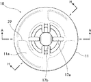
図2〜図11を参照して、第1クリップ10について説明する。図2は本発明の1実施形態のスタッド係止具の第1クリップの平面図である。図3は第1クリップの正面図、図4は右側面図、図5は図2のA−A線断面図である。
図3に示すように、第1クリップ10は、中空の内筒部12と、内筒部12の一端に形成されたフランジ11とを有する。内筒部12は、第2クリップ30の外筒部32に挿入される。内筒部12は、スタッド70を受入れるように中空の円筒体に形成され、その内側には、スタッド70に係合する弾性の係止爪13が複数対(図示の例では2対)設けられている。内筒部12は、スタッド70を受入れることの出来る内径を有し、第2クリップ30の外筒部32に挿入できる外径を有する。内筒部12が取付部材51の取付孔に挿入されると、フランジ11は、取付部材51の一方の面(上面)に接面する。
(First clip)
The
As shown in FIG. 3, the
図3、4に示すように、内筒部12は、下部のリング状のベース部12aと、上部のリング状の頂部12bと、ベース部12aと頂部12bとの間に軸方向に延びる側壁部12cとからなる。
ベース部12aと頂部12bとの間には、軸線方向に延びる複数個(図示の例では2個)のリブ21が形成される。図3のB−B線断面図である図8に示すように、対向するリブ21の間の間隔は、スタッド70の外径より少し大きい。リブ21と係止爪13とにより、スタッド70を受入れるスタッド受入空間24を形成し、受入れたスタッド70を第1クリップ10の軸心に一致するように規制する。
As shown in FIGS. 3 and 4, the
A plurality (two in the illustrated example) of
図3のD−D線断面図である図6に示すように、リブ21の外側は、上下の中間部分で軸心に近くなり、凹状になっている。
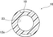
図3のF−F線断面図である図10に示すように、内筒部12のベース部12aは、リブ21の下側に凹み部19が形成されている。
As shown in FIG. 6 which is a sectional view taken along the line D-D of FIG. 3, the outer side of the
As shown in FIG. 10, which is a cross-sectional view taken along line FF in FIG. 3, the
側壁部12cの基部から、対向する1対のアーム16bがスタッド受入空間24の内側に斜め上方に向かって延びる。それぞれのアーム16bには、下側係止爪13bが支持されている。側壁部12cの中間部分から、別の対向する1対のアーム16aがスタッド受入空間24の内側に斜め上方に向かって延びる。それぞれのアーム16aには、上側係止爪13aが支持されている。
スタッド受入空間24にスタッド70が挿入されると、アーム16a,bが弾性的に撓んでスタッド70を受入れる。係止爪13a,bの爪先端は、スタッド70のねじ山の間のねじ溝に入り込んで係合し、第1クリップ10をスタッド70に固定する。アーム16a,bが弾性的に撓むので、第1クリップ10を適度の力でスタッド70へ押込むことができる。係止爪13a,bが係合すると、抜けにくく強固に固定できる。対向する係止爪13a,bは、スタッド70のねじのピッチに合わせて相互に高さ位置がずれている。
A pair of
When the
本発明の係止爪13a,bは、異なるねじピッチを有する2種類のスタッドに係止することが出来るようになっている。本実施形態では、ねじピッチ1.0mmのM6スタッドボルトと、ねじピッチ1.6mmのT6スタッドボルトとに係止することが出来る。
図3のG部分の拡大図である図11は、下側係止爪13bを示す。上側係止爪13aも同じ形状である。各々の下側係止爪13bは、上端部の爪先端61bと、中間の爪先端62bと、下端部の爪先端63bとを有する。爪先端61bと爪先端62bとの間は、谷部64bである。爪先端62bと爪先端63bとの間は、谷部64bより平坦部が長い谷部65bである。各々の上側係止爪13aも同様に、爪先端と谷部とを有する。
The locking
FIG. 11, which is an enlarged view of a portion G in FIG. 3, shows the
上端部の爪先端61bと下端部の爪先端63bとは、M6スタッドボルトと、T6スタッドボルトとの両方のねじ溝に入ることが出来る。中間の爪先端62bは、M6スタッドボルトのねじ溝に入ることが出来、T6スタッドボルトのねじ山の間の部分に入ることが出来る。
このように、本実施形態の係止爪13a,bは、M6スタッドボルトとT6スタッドボルトとの両方に係合することが出来る。
The
Thus, the locking
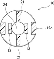
図3に戻って、内筒部12と、フランジ11との間には、内筒部12より小径の首部17が設けられる。図4のC−C線断面図である図9に示すように、首部17の内側には、リブ21の上の対向する位置に2対の凸部17bが形成され、係止爪13の上の対向する位置に1対の凸部17aが形成される。対向する凸部17aと凸部17bとにより、スタッド70がスタッド受入空間24に位置するように規制する。
首部17に隣接する内筒部12の頂部12bの端部は、係止肩18であり、第1クリップ10を第2クリップ30に連結するための連結手段として作用する。図3、4に示すように、係止肩18は、外周のほぼ全周に渡って形成され、内筒部12を第2クリップ30の外筒部32に挿入すると、外筒部32の係止部39が係止肩18に係合して、第2クリップ30と第1クリップ10とが相互に連結される。
Returning to FIG. 3, a
The end portion of the
図2のA−A線断面図である図5に示すように、フランジ11上面から軸心に沿って首部17まで、下の方が狭くなるテーパ状のテーパ部14が形成されている。テーパ部14は、内筒部12の頂部12bのスタッド通し孔15の部分に続く。スタッド通し孔15は、スタッド70の直径より少し大きい内径を有し、スタッド70が第1クリップ10の軸心に位置するように規制するが、ねじには係合しない。フランジ11の上面には、六角レンチ用の孔は形成されていない。
テーパ部14が形成されているので、フランジ11上面からテーパ部14を見ると、スタッド70の先端部分を肉眼で確認することが出来る。第1クリップ10がスタッド70に十分係合していないと、スタッド70の先端部分を十分に見ることができないので、係合が不十分であると直ぐに確認することが出来る。
As shown in FIG. 5, which is a cross-sectional view taken along the line AA in FIG. 2, a tapered
Since the tapered
図5、6、7に示すように、凸部17a、17bは、フランジ11の上面からスタッド通し孔まで伸びている。マイナスドライバー等の工具をテーパ部14に挿入し工具の先端を凸部17b又は凸部17aに引っ掛け、内筒部12を含む第1クリップ10の全体をスタッド70の軸回りに回転させることができる。工具により、内筒部12を含む第1クリップ10の全体をスタッド70の軸回りに回転させ、係止爪13を更に強くスタッド70へ係合させることが出来る。又、工具により、第1クリップ10を逆回転させて締め付けを解除させることが出来る。更に、後述するように、工具により、第1クリップ10を回転させて、フランジ11の下面の溝部を取付部材の突起に収容させることが出来る。
As shown in FIGS. 5, 6, and 7, the
図21は、スタッド係止具1を用いて、取付部材51をスタッド70付きの被取付部材52に取付けた状態を示す断面図である。図22は、図21のJ部分の拡大図である。
フランジ11の下面には、複数個の溝部27が直線状に平行に並んで形成されている。溝部27は、取付部材51の上面に形成された突起56を受入れる。溝部27の両側には凸部29が形成されている。取付部材の突起56は、溝部27に係合して、第1クリップ10が内筒部12の軸線回りに回転するのを防止する。第1クリップ10を第2クリップ30に押込んで連結した後、第1クリップ10を小さな角度だけ回転させると、いずれかの溝部27に突起56が収容され、スタッド係止具1が使用中に緩まないように維持することができる。なお、溝部27には取付部材の突起56が係合しているが、作業者が取付部材を取外す場合には第1クリップ10を回転させることができ、第1クリップ10をスタッド70の軸線回りに回転させて係止爪13をスタッド70のねじ山から外し、第1クリップ10をスタッド70から取外すことができる。
FIG. 21 is a cross-sectional view showing a state in which the
On the lower surface of the
図5に示すように、内筒部12のベース部12aには、上方へ向かって狭くなるテーパが付いたガイド部23が形成されている。ガイド部23は、スタッド受入空間24に連続している。第1クリップ10のガイド部23により、スタッド70の先端部はスタッド受入空間24に案内され、第1クリップ10の係止爪13をスタッド70のねじ山に係合させることが出来る。ガイド部23の角度が大きすぎると、第1クリップ10のベース部12aからアーム16までの距離を多くとる必要が有り第1クリップ10が大きくなる。ガイド部23の角度が小さすぎると、スタッドの先端部が、ガイド部23の入口に入りにくくなる。ここに、ガイド部23の角度とは、図5において、軸心に対して対向するガイド部23の表面がなす角度である。ガイド部23の角度は115〜135°が好ましい。1実施例では、ガイド部23の角度は124°である。
As shown in FIG. 5, a
(第2クリップ)
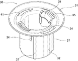
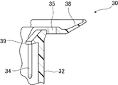
図12〜図20を参照して、第2クリップ30について説明する。図12は第2クリップ30の斜視図、図13は平面図、図14は正面図、図15は底面図、図16は右側面図である。
第2クリップ30は、中空の外筒部32と、外筒部32の一端に形成されたフランジ31とを備える。外筒部32は、第1クリップ10の内筒部12を収容する。フランジ31の上面は、取付部材51の他方の面(下面)に接面する。フランジ31の外縁部には、斜め上方に向かって延びる弾性縁部38が形成されている。弾性縁部38は、取付部材51の下面を第1クリップ10のフランジ11に向けて弾性的に押圧する。フランジ31の弾性縁部38は、取付部材51に圧接するようにフランジ31の縁部に張出して形成されているのが好ましい。
図13、図13のD−D線断面図である図18に示すように、フランジ31の第2クリップ30の軸心を中心にして対向し、円周方向に細長い2つのフランジ孔41が形成されている。フランジ孔41は、弾性縁部38が弾性的に撓むのを助ける。
(Second clip)
The
The
As shown in FIG. 18 which is a sectional view taken along the line D-D in FIGS. 13 and 13, two
外筒部32は、第1クリップ10の内筒部12を受入れるように、内筒部12より大きい内径を持つ中空円筒に形成される。
外筒部32は係止部39を有する。係止部39は、第1クリップ10に第2クリップ30を連結するための第2クリップ側の連結手段として作用する。図16に示すように、係止部39は、外筒部32の軸線方向に延びる一対の側部スリット34により、外筒部32から分離されている。また、図13のA−A線断面図である図17、図17のC部分の拡大図である図20に示すように、係止部39は、上面スリット35によって外筒部32の本体から分離されている。そのため、係止部39は、弾性的に撓みやすい。また、係止部39の係止肩との係合面は、図20に示すように、角度(実施例では14°)をもって成形されており、第1クリップが外れ難くなっている。
The
The
第1クリップ10の内筒部12が外筒部32に挿入され、係止部39が首部17の外周部に来ると、係止部39は、第1クリップ10の連結手段としての係止肩18に容易に弾性的に係合する。係止部39は、第1クリップ10への連結を確実に維持するため、複数個(図示の実施形態では2個)設けられる。
When the inner
図13のH−H線断面図である図19に示すように、第2クリップ30の軸心に対してフランジ孔41、上面スリット35がない方向では、フランジ31と外筒部32とは、連続している。
図14、15に示すように、外筒部32の外側面には、外筒部32の強度を高くするための軸線方向に延びるリブ37が複数本(図示の実施形態では4本)形成されている。図19はリブ37の部分の断面を示す。
As shown in FIG. 19, which is a cross-sectional view taken along the line HH in FIG. It is continuous.
As shown in FIGS. 14 and 15, a plurality of ribs 37 (four in the illustrated embodiment) extending in the axial direction for increasing the strength of the
再度、スタッド係止具1により、取付部材51をスタッド70付きの被取付部材52に取付けた状態を示す図21を参照する。スタッド係止具1は、第2クリップ30と第1クリップ10とを備える。スタッド係止具1は、第2クリップ30と第1クリップ10とが取付部材51を間に挟んで相互に連結され、取付部材51を一定の挟持力で挟持する。その挟持力により、第2クリップ30のフランジ31と第1クリップ10のフランジ11とが取付部材51をスタッド70の軸線方向にはがたつかないように挟持する。この挟持力により、取付部材51の突起56が第1クリップ10のフランジ11の下面の溝部27から外れないように押圧される。フランジ31の弾性縁部38によって、取付部材51のがたつきが防止され、第1クリップ10と第2クリップ30の、軸線周りの相対回転が防止される。取付部材51が被取付部材52から外れるのが防止される。温度変化により取付部材51が膨張又は収縮した場合、取付部材51は、面方向へは移動することができる。
Reference is again made to FIG. 21 showing a state in which the
(スタッド係止具の取付)
図21を参照して、このような構成の第1クリップ10と第2クリップ30とからなるスタッド係止具1を取付部材51を挟持するように取付け、次に、スタッド係止具1付きの取付部材51をスタッド70が固着された被取付部材52に取付ける動作を説明する。
スタッド係止具1を取付部材51に取付けるには、第1クリップ10の内筒部12を取付部材51の取付孔53に挿入できるように位置決めし、第2クリップ30の外筒部32を、取付孔53に挿入される内筒部12を受入れるように位置決めする。第1クリップ10を、取付孔53に内筒部12を挿入するように押込む。次に、第2クリップ30を、外筒部32が第1クリップ10の内筒部12を収容するように押込む。
(Attaching the stud lock)
Referring to FIG. 21, the
In order to attach the
この動作により、第1クリップ10のフランジ11と第2クリップ30のフランジ31との間に取付部材51が挟まれる。更に、第1クリップ10と第2クリップ30を相互に押圧するように押込むと、第1クリップ10の内筒部12の首部17の係止肩18に第2クリップ30の係止部39が係止される。第1クリップ10の係止肩18と第2クリップ30の係止部39とが係止されると、第1クリップ10と第2クリップ30とが相互に連結され、第1クリップ10のフランジ11と第2クリップ30のフランジ31とによって、取付部材51が挟持される。このとき、第2クリップ30のフランジ31の外縁部の弾性縁部38が取付部材51を圧接して、取付部材51を所定の挟持力で挟持する。
By this operation, the
図22は、図21のJ部分の拡大図である。第1クリップ10のフランジ11と第2クリップ30のフランジ31との間に取付部材51が挟持されるとき、第1クリップ10のフランジ11の下面の溝部27に、取付部材51に形成された突起56が収容される。溝部27の断面形状は、突起56の形状に合わせて形成されるのが好ましい。
これらの溝部27に突起56が収容されることにより、第1クリップ10と第2クリップ30の軸線周りの相対回転が防止され、スタッド係止具1の使用中に緩むのを防止できる。
FIG. 22 is an enlarged view of a portion J in FIG. When the mounting
By accommodating the
溝部27の縁部には、凸部29が形成されている。作業者が取付部材51を取外す場合には第1クリップ10のテーパ部14にマイナスドライバー等の工具を挿入し、第1クリップ10をスタッド70の軸線回りに回転させて、係止爪13をスタッド70から外すことが出来る。
取付部材51に複数の所定位置に取付孔53が形成されている場合には、対応する取付孔53に、第1クリップ10と第2クリップ30とを備えるスタッド係止具1が取付けられる。
A
When attachment holes 53 are formed at a plurality of predetermined positions in the
被取付部材52が例えば自動車のパネルの場合には、その後、このようにスタッド係止具1が取付けられた取付部材51は、自動車の組立てライン等に搬入される。
組立作業者は、スタッド係止具1が取付けられた取付部材51を、自動車のパネル等の被取付部材52の所定位置に位置決めする。被取付部材52に固着した複数のスタッド70のそれぞれが、スタッド係止具1の第1クリップ10の内筒部12の中空部分に受入れられるように、取付部材51を位置決めする。スタッド係止具1が取付部材51に先付けされているので、作業者は、スタッド係止具1を持つ作業がなく、取付部材51のスタッド係止具1をスタッド70に位置決めする作業に専念することができる。この位置決めのときには、第1クリップ10のガイド部23を利用して、スタッド70の先端を第1クリップ10のスタッド受入空間24に容易に案内することができる。
When the mounted
The assembling worker positions the mounting
位置決め作業の後、第1クリップ10の内筒部12の内側のスタッド受入空間24にスタッド70を受入れるように、取付部材51を被取付部材52に押付ける。この動作により、スタッド70がスタッド受入空間24に挿入され、内筒部12の内側に形成された係止爪13が外側に撓んでスタッド70を受入れる。更に押付けると、係止爪13はスタッド70の側面のねじ上をスライドする。第2クリップ30の外筒部32の下面が被取付部材52に当接すると、係止爪13はスライドを停止してスタッド70のねじ山に係合して、取付部材51が被取付部材52に固定される。
After the positioning operation, the mounting
取付部材51を被取付部材52に取付けた後、更に、第1クリップ10のフランジ11のテーパ部14にマイナスドライバーを挿入して、第1クリップ10をスタッド70の軸回りに回転させ、第1クリップ10の係止爪13を更にきつく係合させることができる。又、第1クリップ10のテーパ部14にマイナスドライバーを挿入して、第1クリップ10を逆転させてその締め付けを解除し、取付部材51を被取付部材52から取外すこともできる。
After the
(係止爪のピッチ)
図23は、図21のスタッド係止具を不完全ねじ部を有するスタッドに取付けた状態を示す断面図である。スタッド70は、基部に近い部分に、不完全ねじ部71が形成されている。不完全ねじ部71は、ねじ山を少し潰したような形状である。スタッド70に取付部材51を取付けるとき、スタッド係止具ではなく、ナットで取付部材51をスタッド70に取付ける場合がある。ナットが緩まないようにするため、不完全ねじ部71を設けている。
また、スタッド70の先端部近くにも、不完全ねじ部72がある。不完全ねじ部72は、スタッド70のねじ山を成形するときに出来る。
本実施形態のスタッド係止具1を用いる場合、係止爪13a,bが不完全ねじ部71,72と係合すると、不完全ねじ部71,72と係止爪13a,bとの接触は不安定となる。
(Patch pitch)
FIG. 23 is a cross-sectional view showing a state in which the stud locking tool of FIG. 21 is attached to a stud having an incomplete thread portion. The
There is also an
When the
本実施形態では、スタッド70に係止する係止爪13は上下に2段設けられている。不完全ねじ部71はスタッド70の基部にあり、不完全ねじ部72はスタッド70の先端近くにある。従来は、対を成す上側係止爪13aと下側係止爪13bとを上下方向に大きくずらしていた為、上側係止爪13aの爪先端は、不完全ねじ部72のねじ山に当接する箇所があり、下側係止爪13bの爪先端は、不完全ねじ部71のねじ山に当接する箇所があった。
対を成す上側係止爪13aと下側係止爪13bとの上下方向のずらしを小さくすれば、上側係止爪13aの爪先端は、不完全ねじ部72のねじ山に当接しにくく、下側係止爪13bの爪先端は、不完全ねじ部71のねじ山に当接しにくくなる。
In this embodiment, the latching
If the vertical shift between the
本実施形態の第1クリップ10の実施例では、一対の下側係止爪13bのうち低い方(図23の右側)の係止爪13bの上側の爪先端61bまでの高さlbは、被取付部材の上面から9.6mm(従来は8.6mm)である。そのため、下側係止爪13bは下側の不完全ねじ部71に当接し難くなる。
また、一対の上側係止爪13aのうち高い方(図23の左側)の係止爪13aの上側の爪先端61aの、被取付部材52の上面からの高さlaは15.1mm(従来は16.1mm)である。そのため、上側係止爪13aは、上側の不完全ねじ部72に当接し難くなる。
低い方の下側係止爪13bの上側の爪先端61bから、高い方の上側係止爪13aの上側の爪先端61aまでの距離la-lbは5.5mm(従来は7.5mm)であり、爪先端61,62,63は不完全ねじ部71,72に当接し難くなっている。
In the lower height lb to the
Also, the higher of the pair of
The distance la-lb from the
本実施形態によれば、第1クリップのフランジ11と、第2クリップのフランジ31とで取付部材51を挟持し、第1クリップ10の内筒部12の内側のスタッド受入空間24に、スタッド70を挿入し、係止爪13をスタッド70のねじ山に係合させることによって、被取付部材52に取付部材51を簡単に確実に取付けることが出来る。
また、テーパ部14からスタッド70の頭部を見ることが出来るので、スタッド70に対して第1クリップ10が完全に取付けられているか簡単に確認することが出来る。
According to this embodiment, the mounting
Further, since the head of the
1 スタッド係止具
2 第1クリップ
3 第2クリップ
4 係止爪
5 取付部材
6 被取付部材
7 スタッド
8 六角孔
9 取付孔
10 第1クリップ
11 第1クリップのフランジ
11a 凹部
12 内筒部
12a ベース部
12b 頂部
12c 側壁部
13 係止爪
13a 上側係止爪
13b 下側係止爪
14 テーパ部
15 スタッド通し孔
16a,16b アーム
17 首部
17a,17b 凸部
18 係止肩
19 凹み部
21 リブ
22 十字型リブ
23 ガイド部
24 スタッド受入空間
27 溝部
29 凸部
30 第2クリップ
31 第2クリップのフランジ
32 外筒部
34 側部スリット
35 上面スリット
37 リブ
38 弾性縁部
39 係止部
41 フランジ孔
51 取付部材
52 被取付部材
53 取付孔
56 突起
61a,b, 62a,b, 63a,b 爪先端
64a,b, 65a,b 谷部
70 スタッド
71,72 不完全ねじ部
1 Stud lock
2 First clip
3 Second clip
4 Locking claw
5 Mounting member
6 Mounted member
7 Stud
8 Hexagon socket
9 Mounting hole
10 First clip
11 Flange of the first clip
11a recess
12 Inner tube
12a Base part
12b top
12c Side wall
13 Locking claw
13a Upper locking claw
13b Lower locking claw
14 Taper
15 Stud through hole
16a, 16b arm
17 neck
17a, 17b Convex part
18 Locking shoulder
19 dent
21 Ribs
22 Cross-shaped rib
23 Guide section
24 Stud receiving space
27 Groove
29 Convex
30 Second clip
31 Flange of the second clip
32 Outer tube
34 Side slit
35 Top slit
37 Ribs
38 Elastic edge
39 Locking part
41 Flange hole
51 Mounting member
52 Mounted member
53 Mounting hole
56 Protrusions
61a, b, 62a, b, 63a, b Nail tip
64a, b, 65a, b Valley
70 Stud
71,72 Incomplete thread
Claims (8)
前記第1クリップは、取付部材の取付孔に挿入される中空の内筒部と、前記内筒部の一端に設けられたフランジと、前記内筒部の内側に形成され、前記スタッドのねじ山に係合する係止爪と、前記第2クリップに連結するための連結手段とを有し、
前記第2クリップは、前記第1クリップの内筒部を収容する中空の外筒部と、前記外筒部の一端に設けられたフランジと、前記第1クリップに連結するための連結手段とを有し、
前記第1クリップの前記フランジの上面から軸心に沿って前記内筒部に向かって狭くなるテーパ部が形成され、前記フランジの上面から前記テーパ部を通して、前記スタッドの先端部分を見ることが出来、前記テーパ部には前記フランジの上面から前記テーパ部に延びる凸部が形成されていることを特徴とするスタッド係止具。 A first clip and a second clip are provided, and the first clip and the second clip are connected to each other in a state where the mounting member is sandwiched from both sides, and the stud fixed to the mounted member is received in the stud receiving space. A stud locking tool that is fixed to the mounted member by being locked to the stud, and that attaches the mounting member to the mounted member,
The first clip is formed on a hollow inner cylinder portion inserted into an attachment hole of an attachment member, a flange provided at one end of the inner cylinder portion, and an inner side of the inner cylinder portion. A locking claw that engages with the second clip, and a coupling means for coupling to the second clip,
The second clip includes a hollow outer tube portion that accommodates the inner tube portion of the first clip, a flange provided at one end of the outer tube portion, and a connecting means for connecting to the first clip. Have
A tapered portion that narrows from the upper surface of the flange of the first clip along the axial center toward the inner cylinder portion is formed, and the tip end portion of the stud can be seen from the upper surface of the flange through the tapered portion. , stud fastener in the tapered portion, characterized that you have formed a convex portion extending in the tapered portion from an upper surface of said flange.
前記第1クリップの前記フランジは、前記第1クリップの前記内筒部を前記取付部材の前記取付孔に挿入した状態で、前記取付部材の一方の面に接し、
前記第2クリップの前記フランジは、前記第1クリップの前記内筒部を前記第2クリップの前記外筒部に収容した状態で、前記取付部材の他方の面に接するスタッド係止具。 The stud lock according to claim 1,
The flange of the first clip is in contact with one surface of the mounting member in a state where the inner cylindrical portion of the first clip is inserted into the mounting hole of the mounting member.
The flange of the second clip is a stud locking tool that contacts the other surface of the mounting member in a state where the inner cylinder portion of the first clip is accommodated in the outer cylinder portion of the second clip.
前記内筒部は軸心方向に沿って2対の対向する係止爪を有し、
前記内筒部は軸心方向に沿って延びる対向するリブを有し、
前記係止爪と前記リブとにより、前記スタッド受入れ空間を形成するスタッド係止具。 The stud locking tool according to any one of claims 1 to 6,
The inner cylinder portion has two pairs of opposing locking claws along the axial direction,
The inner cylinder part has opposing ribs extending along the axial direction,
The stud locking tool which forms the stud receiving space by the locking claw and the rib.
各々の前記係止爪は、異なるねじピッチを有する2つのスタッドに係合することが出来、異なるねじピッチを有する2つのスタッドのねじ溝に入る複数の第1の爪先端と、一方のスタッドのねじ溝に入る第2の爪先端とを有するスタッド係止具。 The stud locking tool according to any one of claims 1 to 7,
Each said locking claw can be engaged with two studs having different screw pitches, a plurality of first claw tips entering the thread grooves of the two studs having different screw pitches, A stud lock having a second claw tip entering the thread groove.
Priority Applications (6)
| Application Number | Priority Date | Filing Date | Title |
|---|---|---|---|
| JP2012180019A JP5978541B2 (en) | 2012-08-15 | 2012-08-15 | Stud lock |
| CN201380051258.8A CN104685230B (en) | 2012-08-15 | 2013-08-09 | Stud stopper |
| PCT/JP2013/071691 WO2014027625A1 (en) | 2012-08-15 | 2013-08-09 | Stud locking tool |
| EP13879311.2A EP2886885B1 (en) | 2012-08-15 | 2013-08-09 | Stud locking tool |
| TW102129363A TWI600838B (en) | 2012-08-15 | 2013-08-15 | A stud fastening device |
| US14/619,824 US9500219B2 (en) | 2012-08-15 | 2015-02-11 | Stud locking device |
Applications Claiming Priority (1)
| Application Number | Priority Date | Filing Date | Title |
|---|---|---|---|
| JP2012180019A JP5978541B2 (en) | 2012-08-15 | 2012-08-15 | Stud lock |
Publications (3)
| Publication Number | Publication Date |
|---|---|
| JP2015121234A JP2015121234A (en) | 2015-07-02 |
| JP2015121234A5 JP2015121234A5 (en) | 2015-09-03 |
| JP5978541B2 true JP5978541B2 (en) | 2016-08-24 |
Family
ID=50685582
Family Applications (1)
| Application Number | Title | Priority Date | Filing Date |
|---|---|---|---|
| JP2012180019A Active JP5978541B2 (en) | 2012-08-15 | 2012-08-15 | Stud lock |
Country Status (6)
| Country | Link |
|---|---|
| US (1) | US9500219B2 (en) |
| EP (1) | EP2886885B1 (en) |
| JP (1) | JP5978541B2 (en) |
| CN (1) | CN104685230B (en) |
| TW (1) | TWI600838B (en) |
| WO (1) | WO2014027625A1 (en) |
Families Citing this family (21)
| Publication number | Priority date | Publication date | Assignee | Title |
|---|---|---|---|---|
| JP5945661B1 (en) * | 2015-06-23 | 2016-07-05 | 和富 岡 | Female thread parts, male thread parts and washer parts |
| JP6533110B2 (en) * | 2015-07-14 | 2019-06-19 | 日立オムロンターミナルソリューションズ株式会社 | Hole cap |
| KR101765631B1 (en) * | 2015-12-14 | 2017-08-07 | 현대자동차 주식회사 | Fastening clip for vehicle |
| CN105564329A (en) * | 2016-02-04 | 2016-05-11 | 成都银利汽车零部件有限公司 | Support adjusting device |
| DE102016212350B4 (en) * | 2016-07-06 | 2020-09-24 | Hansgrohe Se | Screw connection and plumbing connection box |
| EP3339664B1 (en) * | 2016-12-21 | 2021-09-15 | Newfrey LLC | Fastening element, arrangement with a fastening element and method of installing a fastening element |
| CN107339308A (en) * | 2016-12-28 | 2017-11-10 | 安徽江淮汽车集团股份有限公司 | A kind of double thread connection can pre-install buckle |
| JP6851850B2 (en) | 2017-02-16 | 2021-03-31 | ポップリベット・ファスナー株式会社 | Sheet-shaped member fixture |
| TWI685699B (en) | 2018-05-11 | 2020-02-21 | 友達光電股份有限公司 | Backlight module and connecting unit |
| KR101978424B1 (en) * | 2018-05-21 | 2019-05-14 | 주식회사 에이티에스 | Washer assembly and assembling method of the same |
| JP6869924B2 (en) * | 2018-07-23 | 2021-05-12 | ポップリベット・ファスナー株式会社 | Stud lock |
| WO2020059680A1 (en) * | 2018-09-18 | 2020-03-26 | 株式会社パイオラックス | Fastener |
| EP3850147B1 (en) | 2018-11-14 | 2022-06-15 | Samsung Electronics Co., Ltd. | Water transmission device and washing machine including the same |
| KR20200080620A (en) | 2018-12-27 | 2020-07-07 | 삼성전자주식회사 | Stud |
| US11486422B2 (en) * | 2019-03-27 | 2022-11-01 | Illinois Tool Works Inc. | Adaptable push-on stud fastener |
| KR102141902B1 (en) * | 2019-05-15 | 2020-08-06 | 주식회사 니프코코리아 | Push nuts for cars |
| DE102020117633A1 (en) | 2020-07-03 | 2022-01-05 | hmg gmbh | Device for producing plug connections, method for producing plug connections and use of the device |
| EP4063670A1 (en) * | 2021-03-22 | 2022-09-28 | Newfrey LLC | Fastener and arrangement comprising a fastener |
| CN115199634A (en) * | 2021-04-09 | 2022-10-18 | 伊利诺斯工具制品有限公司 | Connecting piece |
| USD992404S1 (en) * | 2021-08-16 | 2023-07-18 | Gripple Limited | Anchor device |
| USD994478S1 (en) * | 2021-08-16 | 2023-08-08 | Gripple Limited | Anchor device |
Family Cites Families (21)
| Publication number | Priority date | Publication date | Assignee | Title |
|---|---|---|---|---|
| JPS602334Y2 (en) * | 1980-07-15 | 1985-01-23 | 株式会社ニフコ | Natsuto |
| US4850778A (en) * | 1988-07-27 | 1989-07-25 | Trw, Inc. | Push-on fastener |
| JP2524861Y2 (en) * | 1991-12-09 | 1997-02-05 | 矢崎総業株式会社 | Locking part structure for bolt locking |
| FR2704027B1 (en) | 1993-04-13 | 1995-12-01 | Trw Carr France Sa | Retaining element, in particular for bodywork of motor vehicles. |
| JP3212434B2 (en) * | 1993-12-17 | 2001-09-25 | 株式会社東郷製作所 | Holding tool |
| FR2733817B1 (en) * | 1995-05-03 | 1997-08-01 | Comet | FIXING PART TO BE MOUNTED ON A LOCKING DOWEL |
| US5660513A (en) * | 1995-07-19 | 1997-08-26 | Illinois Tool Works Inc. | Stud clip having different insertion/withdrawal forces |
| JP4005190B2 (en) * | 1997-11-10 | 2007-11-07 | ポップリベット・ファスナー株式会社 | Stud lock |
| FR2786845B1 (en) * | 1998-12-02 | 2001-01-26 | Rapid Sa | FASTENING FASTENER, PARTICULARLY FOR CABLES, PIPING OR THE LIKE |
| FR2873771B1 (en) * | 2004-07-30 | 2008-08-15 | I T W De France Sas | FEMALE FITTING AND SHUTTER COMPRISING THE SAME |
| US20060099049A1 (en) * | 2004-11-05 | 2006-05-11 | Peterson Rex J | Fastener/stud retainer |
| DE102005015033A1 (en) * | 2005-03-31 | 2006-10-05 | Newfrey Llc, Newark | Fastening element for attachment to a threaded bolt |
| JP4850573B2 (en) * | 2006-04-24 | 2012-01-11 | ポップリベット・ファスナー株式会社 | Fixtures and mounting devices such as under covers |
| JP5088082B2 (en) * | 2007-10-15 | 2012-12-05 | ポップリベット・ファスナー株式会社 | Mounting structure of aerodynamic cover for improving aerodynamic performance |
| JP4972566B2 (en) | 2008-01-10 | 2012-07-11 | 日立オートモティブシステムズ株式会社 | Control method and control apparatus for automatic transmission |
| JP2009162358A (en) | 2008-01-10 | 2009-07-23 | Daiwa Kasei Ind Co Ltd | Fixing clip for stud bolt |
| GB0804196D0 (en) * | 2008-03-06 | 2008-04-16 | Newfrey Llc | Fastener for automotive components |
| JP4789967B2 (en) * | 2008-04-14 | 2011-10-12 | 株式会社ニフコ | Goods holder |
| DE202008007632U1 (en) * | 2008-06-06 | 2008-08-21 | Newfrey Llc, Newark | Fastening element for fastening to a bolt |
| DE202009011986U1 (en) | 2009-08-28 | 2009-12-10 | Illinois Tool Works Inc., Glenview | Device for connecting two components |
| WO2011123323A1 (en) | 2010-04-02 | 2011-10-06 | Illinois Tool Works Inc. | Vibration-isolating vehicle attachment assembly |
-
2012
- 2012-08-15 JP JP2012180019A patent/JP5978541B2/en active Active
-
2013
- 2013-08-09 CN CN201380051258.8A patent/CN104685230B/en active Active
- 2013-08-09 WO PCT/JP2013/071691 patent/WO2014027625A1/en active Application Filing
- 2013-08-09 EP EP13879311.2A patent/EP2886885B1/en active Active
- 2013-08-15 TW TW102129363A patent/TWI600838B/en active
-
2015
- 2015-02-11 US US14/619,824 patent/US9500219B2/en active Active
Also Published As
| Publication number | Publication date |
|---|---|
| CN104685230A (en) | 2015-06-03 |
| EP2886885B1 (en) | 2017-09-27 |
| EP2886885A1 (en) | 2015-06-24 |
| JP2015121234A (en) | 2015-07-02 |
| US9500219B2 (en) | 2016-11-22 |
| CN104685230B (en) | 2017-03-08 |
| WO2014027625A1 (en) | 2014-02-20 |
| TWI600838B (en) | 2017-10-01 |
| TW201418587A (en) | 2014-05-16 |
| EP2886885A4 (en) | 2016-03-30 |
| US20150152910A1 (en) | 2015-06-04 |
Similar Documents
| Publication | Publication Date | Title |
|---|---|---|
| JP5978541B2 (en) | Stud lock | |
| JP4850573B2 (en) | Fixtures and mounting devices such as under covers | |
| JP4276196B2 (en) | Vehicle roof antenna mounting device | |
| US20080141501A1 (en) | Clip | |
| US6824203B2 (en) | Apparatus and method for attaching undercover onto underside of car floor panel | |
| JP2015121234A5 (en) | ||
| KR102363136B1 (en) | Locking retainer system for automotive assembly | |
| US11255365B2 (en) | Fastener assembly | |
| JP2587328Y2 (en) | Pipe holder | |
| JP4674292B2 (en) | clip | |
| WO2015049909A1 (en) | Stud locking tool | |
| US11493078B2 (en) | Stud locking tool | |
| JPH0645184U (en) | Pipe holder | |
| CN114198374A (en) | A connecting system for connecting at least two, in particular plate-like, elements; assembly comprising such a connection system | |
| JP2009162358A (en) | Fixing clip for stud bolt | |
| JP2005090681A (en) | Clip | |
| JP4971247B2 (en) | Stud bolt fixing clip | |
| JP6322447B2 (en) | Mounting member fixing structure | |
| JP5952712B2 (en) | Mounting structure for mounting tool and vehicle exterior member | |
| JPH07243416A (en) | Stud fixture | |
| JP2009180306A (en) | Bolt lock tool for stud bolt or the like | |
| JPH11257329A (en) | Stud locking tool | |
| JPH0519661Y2 (en) | ||
| JP2023075538A (en) | roof snow guard | |
| JP3101474U (en) | Screw grommet |
Legal Events
| Date | Code | Title | Description |
|---|---|---|---|
| A521 | Request for written amendment filed |
Free format text: JAPANESE INTERMEDIATE CODE: A523 Effective date: 20150717 |
|
| A621 | Written request for application examination |
Free format text: JAPANESE INTERMEDIATE CODE: A621 Effective date: 20150717 |
|
| A131 | Notification of reasons for refusal |
Free format text: JAPANESE INTERMEDIATE CODE: A131 Effective date: 20160427 |
|
| A521 | Request for written amendment filed |
Free format text: JAPANESE INTERMEDIATE CODE: A523 Effective date: 20160610 |
|
| TRDD | Decision of grant or rejection written | ||
| A01 | Written decision to grant a patent or to grant a registration (utility model) |
Free format text: JAPANESE INTERMEDIATE CODE: A01 Effective date: 20160704 |
|
| A61 | First payment of annual fees (during grant procedure) |
Free format text: JAPANESE INTERMEDIATE CODE: A61 Effective date: 20160708 |
|
| R150 | Certificate of patent or registration of utility model |
Ref document number: 5978541 Country of ref document: JP Free format text: JAPANESE INTERMEDIATE CODE: R150 |
|
| R250 | Receipt of annual fees |
Free format text: JAPANESE INTERMEDIATE CODE: R250 |
|
| R250 | Receipt of annual fees |
Free format text: JAPANESE INTERMEDIATE CODE: R250 |
|
| R250 | Receipt of annual fees |
Free format text: JAPANESE INTERMEDIATE CODE: R250 |
|
| R250 | Receipt of annual fees |
Free format text: JAPANESE INTERMEDIATE CODE: R250 |
|
| R250 | Receipt of annual fees |
Free format text: JAPANESE INTERMEDIATE CODE: R250 |