JP5977813B2 - Thermal management system - Google Patents
Thermal management system Download PDFInfo
- Publication number
- JP5977813B2 JP5977813B2 JP2014503675A JP2014503675A JP5977813B2 JP 5977813 B2 JP5977813 B2 JP 5977813B2 JP 2014503675 A JP2014503675 A JP 2014503675A JP 2014503675 A JP2014503675 A JP 2014503675A JP 5977813 B2 JP5977813 B2 JP 5977813B2
- Authority
- JP
- Japan
- Prior art keywords
- electromagnet
- component
- thermally conductive
- gap
- heat sink
- Prior art date
- Legal status (The legal status is an assumption and is not a legal conclusion. Google has not performed a legal analysis and makes no representation as to the accuracy of the status listed.)
- Active
Links
Images

Classifications
-
- H—ELECTRICITY
- H01—ELECTRIC ELEMENTS
- H01S—DEVICES USING THE PROCESS OF LIGHT AMPLIFICATION BY STIMULATED EMISSION OF RADIATION [LASER] TO AMPLIFY OR GENERATE LIGHT; DEVICES USING STIMULATED EMISSION OF ELECTROMAGNETIC RADIATION IN WAVE RANGES OTHER THAN OPTICAL
- H01S5/00—Semiconductor lasers
- H01S5/02—Structural details or components not essential to laser action
- H01S5/024—Arrangements for thermal management
-
- G—PHYSICS
- G05—CONTROLLING; REGULATING
- G05D—SYSTEMS FOR CONTROLLING OR REGULATING NON-ELECTRIC VARIABLES
- G05D23/00—Control of temperature
- G05D23/19—Control of temperature characterised by the use of electric means
- G05D23/1919—Control of temperature characterised by the use of electric means characterised by the type of controller
- G05D23/192—Control of temperature characterised by the use of electric means characterised by the type of controller using a modification of the thermal impedance between a source and the load
-
- G—PHYSICS
- G05—CONTROLLING; REGULATING
- G05D—SYSTEMS FOR CONTROLLING OR REGULATING NON-ELECTRIC VARIABLES
- G05D23/00—Control of temperature
- G05D23/19—Control of temperature characterised by the use of electric means
- G05D23/20—Control of temperature characterised by the use of electric means with sensing elements having variation of electric or magnetic properties with change of temperature
-
- H—ELECTRICITY
- H01—ELECTRIC ELEMENTS
- H01S—DEVICES USING THE PROCESS OF LIGHT AMPLIFICATION BY STIMULATED EMISSION OF RADIATION [LASER] TO AMPLIFY OR GENERATE LIGHT; DEVICES USING STIMULATED EMISSION OF ELECTROMAGNETIC RADIATION IN WAVE RANGES OTHER THAN OPTICAL
- H01S3/00—Lasers, i.e. devices using stimulated emission of electromagnetic radiation in the infrared, visible or ultraviolet wave range
- H01S3/02—Constructional details
- H01S3/04—Arrangements for thermal management
Landscapes
- Physics & Mathematics (AREA)
- General Physics & Mathematics (AREA)
- Engineering & Computer Science (AREA)
- Automation & Control Theory (AREA)
- Electromagnetism (AREA)
- Optics & Photonics (AREA)
- Plasma & Fusion (AREA)
- Condensed Matter Physics & Semiconductors (AREA)
- Cooling Or The Like Of Electrical Apparatus (AREA)
- Heat-Exchange Devices With Radiators And Conduit Assemblies (AREA)
- Control Of Temperature (AREA)
Description
[0001] 電子コンポーネントは、上位および下位目標温度の間における所望の温度範囲内で動作するように設計することができる。例えば、ゲーミング・システム用入力デバイスの1つに深度カメラがある。深度カメラは、通例、オブジェクトを照明光で照らすための光源を備えた照明システムを含む。効率的な動作のためには、光源を所望の動作範囲内に維持しなければならない。 [0001] Electronic components can be designed to operate within a desired temperature range between upper and lower target temperatures. For example, a depth camera is one of input devices for a gaming system. Depth cameras typically include an illumination system with a light source for illuminating an object with illumination light. For efficient operation, the light source must be maintained within the desired operating range.
[0002] 電子コンポーネントにおいて所望の温度範囲を維持する手法には、冷却ファンまたは熱電気クーラ(TEC:thermoelectric cooler)のように、熱管理デバイスを利用することを含むものがある。しかしながら、このような熱管理デバイスは高価であることもあり、ある量の実装空間を必要とすることもあるので、ゲーミング・システムのような、ある種の電子システムには望ましくない。更に、所望の温度範囲を維持するためのこれらおよびその他の手法は、電子コンポーネントに加熱または冷却効果のいずれかを付与することがあるが、コンポーネントを熱的に絶縁する効果が低下する可能性がある。 [0002] Some techniques for maintaining a desired temperature range in an electronic component include utilizing a thermal management device, such as a cooling fan or a thermoelectric cooler (TEC). However, such thermal management devices are expensive and may require a certain amount of mounting space, which is undesirable for certain electronic systems, such as gaming systems. In addition, these and other techniques for maintaining the desired temperature range may impart either a heating or cooling effect to the electronic component, but may reduce the effectiveness of thermally insulating the component. is there.
[0003] 目標コンポーネントを選択的に熱絶縁および熱接続する熱管理システムの種々の実施形態を開示する。一実施形態では、熱管理システムは、目標コンポーネントに近接する第1表面を有する第1コンポーネントを含む。第1表面と目標コンポーネントとの間に、電磁石が位置付けられる。第1および第2コンポーネントの間にギャップができるように、第2コンポーネントは第1コンポーネントから離間されている。このギャップは、コンポーネント間における熱境界の役割を果たす。このギャップ内に搬送流体(carrier fluid)を入れる。搬送流体は、多数の熱伝導性鉄含有粒子を含む。 [0003] Various embodiments of a thermal management system that selectively thermally isolates and thermally connects target components are disclosed. In one embodiment, the thermal management system includes a first component having a first surface proximate to the target component. An electromagnet is positioned between the first surface and the target component. The second component is spaced from the first component so that there is a gap between the first and second components. This gap acts as a thermal boundary between components. A carrier fluid is placed in the gap. The carrier fluid includes a number of thermally conductive iron-containing particles.
[0004] 電磁石が、熱伝導性鉄含有粒子を誘引する磁場を生成するときに、搬送流体はギャップの中央領域を横切ってこれらの粒子の少なくとも一部を整列させるように構成されている。逆に、電磁石が粒子を駆散する磁場を生成するとき、搬送流体はギャップの中央領域から粒子の少なくとも一部を変位させるように構成されている。このように、熱管理システムは、選択的に第1および第2コンポーネントを熱接続および熱絶縁するように動作する。 [0004] When the electromagnet generates a magnetic field that attracts thermally conductive iron-containing particles, the carrier fluid is configured to align at least a portion of these particles across the central region of the gap. Conversely, when the electromagnet generates a magnetic field that dissipates the particles, the carrier fluid is configured to displace at least a portion of the particles from the central region of the gap. In this way, the thermal management system operates to selectively thermally connect and insulate the first and second components.
[0005] この摘要は、詳細な説明の章において以下で更に説明する概念から選択したものを簡略化された形式で紹介するために、設けられている。この摘要は、特許請求する主題の主要な特徴や必須の特徴を特定することを意図するのではなく、特許請求する主題の範囲を限定するために使用されることを意図するのでもない。更に、特許請求する主題は、本開示のいずれの部分に記されるいずれの欠点を解決する実施態様にも、また全ての欠点を解決する実施態様にも限定されない。 [0005] This summary is provided to introduce a selection of concepts in a simplified form that are further described below in the Detailed Description chapter. This summary is not intended to identify key features or essential features of the claimed subject matter, nor is it intended to be used to limit the scope of the claimed subject matter. Furthermore, the claimed subject matter is not limited to embodiments that solve any or all disadvantages noted in any part of this disclosure.
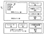
[0013] これより、本開示の態様について、例をあげて、そして先に羅列した例示実施形態を参照しながら説明する。図1は、ゲーミング・システム10の一例を模式的に示す。ゲーミング・システム10は、ゲーム・コンソールのような計算デバイス12と、連携深度カメラ(associated depth camera)20を含む。この深度カメラ20と合わせて、本開示の実施形態による熱管理システムを利用することができる。深度カメラ20は、人28のようなオブジェクトを照らす光を放出し、光センサにおいて、反射した照明光を検知する。深度カメラ20または計算デバイス12内部にある撮像システムは、取り込まれた反射光に基づいてオブジェクトの画像を生成するように構成されている。このオブジェクトの画像は、照らされたオブジェクトの実写表現をディスプレイ36上に提示するために用いることができる。
[0013] Aspects of the present disclosure will now be described by way of example and with reference to the exemplary embodiments listed above. FIG. 1 schematically illustrates an example of a
[0014] 図2は、図1の深度カメラ20および計算デバイス12のコンポーネントを模式的に示す。一例では、深度カメラ20は、コントローラー40、メモリー50、および電源60を含む。また、深度カメラ20は、照明システム18内に配置されている光源14も含む。以下で更に詳しく説明するが、深度カメラ20は、更に、光源14のような目標コンポーネント30を選択的に熱絶縁および熱接続するための、本開示の実施形態による熱管理システム100も含む。照明システム18は、図1における人28のようなオブジェクトを照らすように、光源14を制御することができる。例の中には、照明光が、三次元情報を判定するために分析する干渉パターンを供給する際に用いられる構造化光であるとよい場合がある。他の例の中には、照明光が、三次元情報を判定するために飛行時間測定の基準を規定する際に用いられるパルス光であるとよい場合もある。
FIG. 2 schematically illustrates components of the
[0015] 一例では、光源14は、発光レーザー・ダイオード16のアレイを含む場合もある。この発光レーザー・ダイオード16は、1つ以上の波長で光パルスを放出するように制御される。尚、発光レーザー・ダイオード16は、熱を発生すること、そして発光ダイオード16の動作温度を変化させると、放出される光の発光波長も変化することは認められよう。レーザー・ダイオードの動作温度を上げると、放出される光の波長も対応して上昇する。逆に、レーザー・ダイオードの動作温度を下げると、放出光の波長も対応して下がる。参照と例示の目的に限って、標準的な端面発光ファブリ−ペロー・レーザーの動作温度を理論的に摂氏30°に調節すると、放出光の波長が10nmずれる結果となると考えられる。
In one example, the light source 14 may include an array of light
[0016] 引き続き図2を参照すると、計算デバイス12は、コントローラー72、メモリー73、ならびに付随する大容量記憶デバイス76および電源78を含む。計算デバイス12は、深度カメラ20に動作可能に接続されており、深度カメラからの三次元情報を受け取る。他の例では、深度カメラ20は、コントローラーやメモリーを含まなくてもよく、計算デバイス12のコントローラー72およびメモリー74を、深度カメラおよび熱管理システム100を制御するために用いてもよい。更に他の例では、熱管理システム100を、電源、コントローラー、大容量記憶装置、および/またはメモリーの内1つ以上を備えている他の電子デバイスに埋め込むこと、または動作可能に接続することもできる。したがって、本明細書において説明する熱管理システム100の実施形態は、単なる例示に過ぎず、他の動作のコンテキストでは、他の適した実施形態を本開示の範囲内で採用することもできる。
With continued reference to FIG. 2, the computing device 12 includes a controller 72, memory 73, and associated mass storage device 76 and
[0017] 深度カメラ20内における照明システム18の効率的な動作のためには、発光レーザー・ダイオード16の波長シフトを最小限に抑えることが望ましい。このような波長シフトを最小限に抑える1つの手法は、発光レーザー・ダイオード16の動作温度を所望の温度範囲内に維持することとするとよい。
[0017] For efficient operation of the illumination system 18 within the
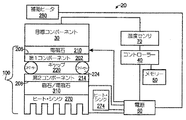
[0018] これより図3を参照すると、目標コンポーネント30、および熱管理システム100のコンポーネントの模式図が示されている。図2を参照して先に説明したように、一例では、目標コンポーネント30は、光源14内にある1つ以上の発光レーザー・ダイオード16であってもよい。
[0018] Referring now to FIG. 3, a schematic diagram of the
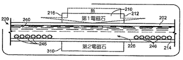
[0019] 一例では、熱管理システム100は、第1コンポーネント202を含むことができる。第1コンポーネント202は、目標コンポーネント30に近接する第1表面206を含む。第1表面206と目標コンポーネント30との間に、第1電磁石210を配置することができる。第1電磁石210は、強磁性コアを包囲するコイルで構成するとよい。一例では、第1電磁石210はドーナツ形状を有するとよい。図3に示すように、第1コンポーネント202の第1表面206は、目標コンポーネント30に近接するとよいが、目標コンポーネントと接触してはならない。他の実施形態では、第1表面206の少なくとも一部が目標コンポーネント30に近接し、これと接触してもよい。例えば、第1電磁石210の幅は、第1コンポーネント202の幅よりも小さくするとよく、第1コンポーネントの外周および第1表面206は、目標コンポーネント30に接触するように延びてもよい。
In one example, the
[0020] 引き続き図3を参照すると、第2コンポーネント214は、第2コンポーネント202から離間され、ギャップ220を形成するとよい。以下で更に詳しく説明するが、ギャップ220は、第1コンポーネント202と第2コンポーネント214との間において熱境界の役割を果たす。第2コンポーネント214は、ヒート・シンク270に近接する第2表面208を含む。
With continued reference to FIG. 3, the
[0021] ヒート・シンク270は、第2コンポーネント214の温度を下げ、これによって第2コンポーネント214と目標コンポーネント30との間における温度差を広げるように動作することができる。以下で更に詳しく説明するが、このように、ヒート・シンク270は、選択的に目標コンポーネント30からの熱転移を強めることができる。他の例では、既存のヒート・シンク274が電子コンポーネント内にあってもよく、これと共に熱管理システム100が用いられる。この実施形態では、既存のヒート・シンク274は、ヒート・シンク270に加えて用いること、またはその代わりに用いることができる。
[0021] The heat sink 270 may operate to reduce the temperature of the
[0022] 一実施形態では、第2表面208とヒート・シンク270との間に、第2磁石310を配置することもできる。第2磁石310は、永久磁石または第2電磁石であってもよい。一例では、第2磁石310は永久磁石とするとよく、コントローラー40は、以下で更に詳しく説明するように、第1電磁石210を選択的に制御するように構成されている。他の例では、第2磁石310は、電源60にも電気的に接続されている第2電磁石であり、コントローラー40は、以下で更に詳しく説明するように、第1電磁石210および第2電磁石を選択的に制御するように構成されている。
[0022] In one embodiment, the
[0023] 図3に示すように、第2コンポーネント214の第2表面208は、ヒート・シンク270に近接するのでよいが、ヒート・シンク270と接触してはいけない。他の実施形態では、第2コンポーネント214の第2表面208の少なくとも一部は、ヒート・シンク270に近接しこれに接触してもよい。例えば、第2磁石310の幅は、第2コンポーネント214の幅よりも小さいとよく、第2コンポーネントの外周および第2表面208は、ヒート・シンク270と接触するように延びてもよい。
[0023] As shown in FIG. 3, the
[0024] 第1コンポーネント202および第2コンポーネント214は、スペーサー224によって分離することができる。スペーサー224は、第1コンポーネントおよび第2コンポーネントの第2熱伝導率よりも低い第1熱伝導率を有する材料で形成されている。スペーサー24に用いることができる材料の例には、ガラス、陶器、プラスチック、およびエラストマー材料が含まれる。図3および図4に示す例では、スペーサー224は、エラストマー材料で形成されたO−リングにするとよい。
[0024] The
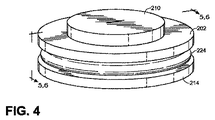
[0025] これより図4を参照すると、一例において、第1コンポーネント202および第2コンポーネント214は、互いに対向して位置付けられた環状プレートを含むことができる。この実施形態では、第1コンポーネント202および第2コンポーネント214は、スペーサー224によって分離され、更にスペーサー224と重なり合ってもよい。スペーサー224は、エラストマー製O−リングで構成するとよい。図4に示すように、この実施形態では、第1電磁石210も同様に、第1コンポーネント202および第2コンポーネント214の直径よりも小さい直径を有する環状プレートを含むことができる。
[0025] Referring now to FIG. 4, in one example, the
[0026] 第1コンポーネント202および第2コンポーネント214は、非鉄材料で形成するとよい。先に注記したように、第1コンポーネント202および第2コンポーネント214も、スペーサー24の第1熱伝導率よりも高い第2熱伝導性を有する材料で形成されている。第1コンポーネント202および第2コンポーネント214に用いるとよい非鉄材料の例には、アルミニウム、亜鉛、および銅が含まれる。
[0026] The
[0027] 引き続き図3を参照すると、第1電磁石210は、電源60に電気的に接続し、第1電磁石を選択的に付勢して、第1コンポーネント202を通過してギャップ220内に伝搬する磁場を生成することができる。電源60は、動作可能にコントローラー40に接続することができる。コントローラー40は、電源から第1電磁石に電流を供給することによって、第1電磁石210を選択的に制御するように構成されている。以下で更に詳しく説明するが、コントローラー40は、温度センサ70に動作可能に接続することができる。温度センサ70は、目標コンポーネント30に動作可能に接続されている。メモリー50にはプログラム論理命令が格納されており、このプログラム論理命令は、電源60を選択的に制御して、第1電磁石210を付勢し、本明細書において記載する機能を設けるためにコントローラー40によって実行される。
Still referring to FIG. 3, the
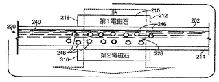
[0028] これより図5および図6を参照すると、第1コンポーネント202と第2コンポーネント214との間におけるギャップ220には、搬送流体240が配置されている。搬送流体240は、多数の熱伝導性鉄含有粒子246を含む。一例では、搬送流体240は、基礎流体と、この基礎流体内に懸濁されている熱伝導性鉄含有ナノ粒子とを含むコロイド溶液を含む。ナノ粒子の各々は、約1から100ナノメートルの間の直径を有するとよく、酸化物、炭化物、鉄のような金属、磁鉄鉱、または赤鉄鉱を含むがこれらに限定されない材料で形成するとよい。
Referring now to FIGS. 5 and 6, a
[0029] 基礎流体は、その中にナノ粒子を懸濁させることができ、水、エチレン・グリコール、またはその他の流体を含む。その一部は、水またはエチレン・グリコールよりも低い熱伝導率を有するものもある。尚、基礎流体の熱伝導率は、熱伝導性鉄含有ナノ粒子の熱伝導率未満であることは認められよう。例えば、エチレン・グリコールは約0.25W/mKの熱伝導率を有すると考えられ、一方鉄は約80W/mKの熱伝導率を有すると考えられる。以下で更に詳しく説明するが、搬送流体240は、第1電磁石210および/または第2磁石310が粒子を誘引する磁場を生成するときに、ギャップ220の中央領域226を横切って、熱伝導性鉄含有粒子246を整列させるように構成されている。また、搬送流体240は、第1電磁石210および/または第2磁石310が粒子を駆散する磁場を生成するときには、ギャップ220の中央領域226から粒子を変位させるように構成されている。
[0029] Base fluids can have nanoparticles suspended therein and include water, ethylene glycol, or other fluids. Some of them have a lower thermal conductivity than water or ethylene glycol. It will be appreciated that the thermal conductivity of the base fluid is less than the thermal conductivity of the thermally conductive iron-containing nanoparticles. For example, ethylene glycol is considered to have a thermal conductivity of about 0.25 W / mK, while iron is considered to have a thermal conductivity of about 80 W / mK. As will be described in more detail below, the
[0030] 尚、熱伝導性鉄含有粒子246をギャップ220の中央領域226を横切って整列させると、このギャップを横切り搬送流体240を介する熱転移を高め、一方ギャップの中央領域から粒子を変位させると、ギャップを横切り搬送流体240を介する熱移転を妨げることは認められよう。また、ギャップ220の中央領域226は、実質的に第1電磁石210に対向して位置付けるとよく、第1電磁石のエッジ212および216を超えて横方向に延びるとよいことも認められよう。他の例では、ギャップ220の中央領域226は、第1電磁石210のエッジ212および216を超えて横方向に延びなくてもよい。
[0030] It should be noted that when the thermally conductive iron-containing
[0031] また図3も参照すると、第1コンポーネント202および第2コンポーネント214はスペーサー224と協同して、搬送流体240が実質的にギャップ220内に静止するように、流体的に密閉された空間を形成する。このように、第1コンポーネント202から搬送流体240を通り目標コンポーネント30に至る熱転移は、伝導性熱転移から成る。
[0031] Referring also to FIG. 3, the
[0032] これより図3を参照すると、目標コンポーネント30の温度は、種々の動作状態やパラメータに応じて、上昇または低下する可能性があることは認められよう。種々の動作状態やパラメータには、目標コンポーネントの動作期間または非動作期間、ならびに目標コンポーネントとその周囲との間の温度差が含まれるが、これらに限定されるのではない。先に説明したように、一例では、目標コンポーネント30は深度カメラ20内部に1つ以上の発光レーザー・ダイオード16を備えることができる。レーザー・ダイオードを動作させると、レーザー・ダイオードの温度変化が、放出される光の発光波長をシフトさせる。
[0032] Referring now to FIG. 3, it will be appreciated that the temperature of the
[0033] これも先に注記したことであるが、レーザー・ダイオード16は、波長のシフトを最小限に抑えるように、目標動作温度以内で動作させることが望ましい。目標動作範囲は、第1閾値温度と第2閾値温度との間であるとよい。一例では、第1閾値温度は摂氏約42.1°であり、第2閾値温度は摂氏約41.9°である。尚、目標コンポーネント30の特定的な要件およびその動作状態にしたがって、第1および第2閾値温度に他の温度を用いる場合もあることは認められよう。加えて、実施形態の中には、第1および第2閾値温度が等しくてもよい場合もある。以下で更に詳しく説明するが、熱管理システム100は、レーザー・ダイオード16を選択的に熱絶縁および熱接続して、レーザー・ダイオードを目標動作温度範囲内に維持することができる。
[0033] As previously noted, it is desirable that the
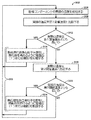
[0034] これより図7に移り、図5および図6に示す実施形態も参照しつつ、レーザー・ダイオード16のような、熱を生成する目標コンポーネントを選択的に熱絶縁および熱接続する方法のフロー・チャートを示す。この方法は、メモリー50に格納されている命令という形態とした制御アルゴリズムを構成することができる。この命令は、コントローラー40によって実行され、図3、図5および図6に示し先に説明したハードウェアおよびコンポーネントによって実行することができる。尚、この方法は、適したハードウェア、ソフトウェア、および/またはコンポーネントであれば他のいずれでも実行できることは認められよう。
[0034] Turning now to FIG. 7, with reference also to the embodiment shown in FIGS. 5 and 6, a method of selectively thermally insulating and thermally connecting a target component that generates heat, such as a
[0035] 一実施形態例では、纏めて328で示すステップ314および324から開始し、第2磁石310は第2電磁石であり、方法328は、熱伝導性鉄含有粒子を誘引するまたは駆散するように、第1電磁石210および/または第2電磁石を制御するステップを含む。更に具体的には、ステップ314において、この方法は、熱伝導性鉄含有粒子246を搬送流体240内に誘引し、これによって粒子の少なくとも一部をギャップ220の中央領域226を横切って整列させる磁場を生成するように、第1電磁石210および/または第2電磁石を制御することを含む。ステップ324において、この方法は、搬送流体240内で熱伝導性鉄含有粒子246を駆散し、これによって粒子の少なくとも一部をギャップ220の中央領域226から変位させる磁場を生成するように、第1電磁石210および/または第2電磁石を制御することも含む。先に説明したが、熱伝導性鉄含有粒子246を説明したようにして整列させると、目標コンポーネント30からギャップを横切りヒート・シンク270に至る熱転移が高まり、一方説明したようにして粒子を変位させると、ギャップを横切り搬送流体240を介した熱転移が妨げられる。
[0035] In one example embodiment, starting with
[0036] 一例では、第1電磁石210および/または第2電磁石を通過する電流は、可能な最も強い磁場(1つまたは複数)を生成する電磁石の最大定格にするとよい。他の例では、電磁石(1つまたは複数)によって生成される磁場(1つまたは複数)の強度を変化させるために、第1電磁石210および/または第2電磁石の最大定格よりも低い値に変調することもできる。また、第1電磁石210および/または第2電磁石を通過する電流は、磁場がない状態を生じさせるために、排除することもできる。
[0036] In one example, the current passing through the
[0037] 他の実施形態例では、ステップ304から開始し、方法302は、目標コンポーネント30の実際の温度を検知するステップを含む。例えば、温度センサ70は、目標コンポーネント30の実際の温度を判定し、この情報をコントローラー40に伝えることができる。次のステップ308において、目標コンポーネントの実際の温度を、第1閾値温度と比較する。第1閾値温度は、例えば、メモリー50に格納され、コントローラー40によってアクセスすることができる。次に、ステップ312において、目標コンポーネントの実際の温度が第1閾値温度よりも高いか否か判定を行う。目標コンポーネントの実際の温度が第1閾値温度よりも高い場合、ステップ314において、方法300は、前述のように、搬送流体240内部に熱伝導性鉄含有粒子246を誘引する磁場を生成するように、第1電磁石210および/または第2電磁石を制御することを含む。ステップ314に続いて、方法300はステップ304に戻り、目標コンポーネント30の実際の温度を再度検知する。
[0037] In another example embodiment, starting at
[0038] これより図3および図5を参照すると、熱伝導性鉄含有粒子246を誘引し、ギャップ220の中央領域226を横切ってこの粒子を整列させることによって、目標コンポーネント30をヒート・シンク270に熱接続し、目標コンポーネント30からヒート・シンク270への熱移転を高める。このように高められた熱移転は、図4において搬送流体240、第2コンポーネント214、および第2電磁石を貫通する破線の矢印によって模式的に示されている。尚、目標コンポーネント30からヒート・シンク270へ移転される熱の少なくとも一部が、第1電磁石210および第2電磁石を通過する可能性があることは認められよう。他の例では、目標コンポーネント30からヒート・シンク270へ移転される熱の少なくとも一部が、第1電磁石210または第2電磁石を通過しない場合もある。
[0038] Referring now to FIGS. 3 and 5, the
[0039] 図7およびステップ312を参照すると、目標コンポーネントの実際の温度が第1閾値温度よりも高くない場合、ステップ316において、目標コンポーネントの実際の温度を第2閾値温度と比較する。第2閾値温度もメモリー50に格納されており、コントローラー40によってアクセスすることができる。次に、ステップ320において、この方法は、実際の温度が第2閾値温度よりも低いか否か判定を行う。実際の温度が第2閾値温度よりも低くない場合、この方法はステップ304に戻り、再度目標コンポーネント30の実際の温度を検知する。目標コンポーネント30の実際の温度が第2閾値温度よりも低い場合、ここで図6を参照して、ステップ324において、この方法は、搬送流体240内で熱伝導性鉄含有粒子246を駆散する磁場を生成するように第1電磁石210および/または第2電磁石を制御することを含み、これによってこの粒子の少なくとも一部をギャップ220の中央領域226から変位させる。ステップ324の後、この方法はステップ304に戻り、再度目標コンポーネント30の実際の温度を検知する。
[0039] Referring to FIG. 7 and step 312, if the actual temperature of the target component is not higher than the first threshold temperature, in
[0040] これより図3および図6を参照すると、熱伝導性鉄含有粒子246を駆散し、粒子の少なくとも一部をギャップ220の中央領域226から変位させることによって、目標コンポーネント30をヒート・シンク270から熱絶縁し、目標コンポーネント30からヒート・シンク270への熱転移を妨げることは認められよう。搬送流体240に関して先に注記したように、基礎流体の熱伝導率は、基礎流体内に懸濁されている熱伝導性鉄含有粒子の熱伝導率よりも低い。つまり、ギャップ220の中央領域226から粒子を変位させることによって、主に基礎流体のみをギャップの中央領域に残して、ギャップを横切る熱移転を妨げるように作用する。このように妨げられた熱移転は、図6において第1コンポーネント202にしか達しない破線矢印によって模式的に示されている。
[0040] Referring now to FIGS. 3 and 6, the
[0041] ギャップ220を横切る熱転移を妨げ、目標コンポーネント30をヒート・シンク270から熱絶縁することによって、目標コンポーネント30の温度は、目標コンポーネントによって生成される熱、または周囲環境内にある他の熱源から目標コンポーネントに移転される熱のために、上昇すると考えられる。図3を参照すると、一実施形態では、補助ヒータ280を利用して、所望通りに、補助熱転移を目標コンポーネント30に対して行うことができる。一使用事例では、レーザー・ダイオード16を含む深度カメラ20を、レーザー・ダイオードの所望動作範囲よりも十分に低い周囲温度の環境を通過するように移動させること、および/またはこの環境において用いることもできる。この例では、目標コンポーネント30は、前述のようにヒート・シンク270から熱絶縁することができ、補助ヒータ280は、レーザー・ダイオード16を加熱し、レーザー・ダイオードの温度をその所望動作温度範囲内まで上昇させるのに必要な時間を短縮するために利用することができる。
[0041] By preventing thermal transfer across the
[0042] 他の例では、搬送流体240が鉄含有流体(ferrofluid)を構成することもでき、この場合、流体全体が、第1電磁石210および第2電磁石によって生成される磁場(1つまたは複数)に応答して移動する。この例では、鉄含有流体が駆散されギャップ220の中央領域226から変位させられると、中央領域は空気または真空によって充填され、目標コンポーネント30をヒート・シンク270から熱絶縁し、目標コンポーネント30からヒート・シンク270への熱移転を妨げる。
[0042] In other examples, the
[0043] 他の例では、搬送流体240は空気を含んでもよく、熱伝導性鉄含有粒子は鉄充填物(filing)を含んでもよい。この例では、鉄充填物が駆散されギャップ220の中央領域226から変位させられると、中央領域は空気によって充填され、目標コンポーネント30をヒート・シンク270から熱絶縁し、目標コンポーネント30からヒート・シンク270への熱移転を妨げる。
[0043] In other examples, the
[0044] 尚、以上で説明した実施形態例は、説明の目的に限って示されたのであること、そして記載した熱管理システムならびに関連する方法およびプロセスは、適した目標コンポーネントであればいずれとでも、および/または適した動作環境であればいずれにおいても、本開示の範囲以内において用いることができることは認められよう。目標コンポーネントの他の例には、電子回路、デバイスおよびコンポーネント、ならびに光電回路、デバイス、およびコンポーネントが含まれる。他の動作環境例には、移動体計算デバイス、クライアント計算デバイス、サーバ計算デバイス、ディスプレイ・デバイス、よび所望の動作範囲において動作するコンポーネントを含む他の電子デバイスが含まれる。これらの例では、以上で説明したコンポーネントおよび/またはプロセスの1つ以上が、動作環境においてホスト電子システム内に存在すること、またはこのホスト電子システムによって設けられることもできる。 [0044] It should be noted that the example embodiments described above have been presented for illustrative purposes only, and that the thermal management system and associated methods and processes described can be any suitable target component. However, it will be appreciated that any suitable operating environment can be used within the scope of the present disclosure. Other examples of target components include electronic circuits, devices and components, and photoelectric circuits, devices, and components. Other example operating environments include mobile computing devices, client computing devices, server computing devices, display devices, and other electronic devices that include components that operate in a desired operating range. In these examples, one or more of the components and / or processes described above may be present in or provided by the host electronic system in the operating environment.
[0045] 尚、本明細書において説明した構成および/または手法は、その性質上例示であって、これらの具体的な実施形態も例も限定的な意味で捕らえてはならないことは言うまでもない。何故なら、多数の変形が可能であるからである。本明細書において説明した具体的な方法は、処理ステップがいずれの数であっても、その1つ以上を表すことができる。したがって、例示された種々の動作は、例示された順序でも、他の順序でも、または並列に実行することもでき、場合によっては省略することもできる。同様に、前述したプロセスの順序も変更することができる。 [0045] It should be noted that the configurations and / or techniques described in the present specification are merely examples in nature, and it should be understood that these specific embodiments and examples should not be taken in a limiting sense. This is because many variations are possible. The specific methods described herein can represent one or more of any number of processing steps. Accordingly, the various illustrated operations can be performed in the illustrated order, in other orders, or in parallel, and in some cases can be omitted. Similarly, the order of the processes described above can be changed.
[0046] 本開示の主題は、本明細書において開示した種々のプロセス、システムおよび構成、ならびにその他の特徴、機能、動作、および/または特性のあらゆる新規で非自明なコンビネーションおよびサブコンビネーションを含むだけでなく、そのいずれの均等物および全ての均等物をも含むこととする。 [0046] The subject matter of this disclosure only includes all novel and non-obvious combinations and sub-combinations of the various processes, systems and configurations disclosed herein, and other features, functions, operations, and / or characteristics. And any and all equivalents thereof are intended to be included.
Claims (20)
前記目標コンポーネントに近接する第1表面を有する第1コンポーネントと、
前記第1表面と前記目標コンポーネントとの間にある第1電磁石と、
前記第1コンポーネントから離間される第2コンポーネントと、
前記第1コンポーネントと前記第2コンポーネントとの間において熱境界の役割を果たすギャップと、
前記ギャップ内部に配置され、基礎流体および多数の熱伝導性鉄含有粒子を含むコロイド溶液を含む搬送流体であって、
前記基礎流体の熱伝導率が、前記基礎流体内に懸濁される前記熱伝導性鉄含有粒子の熱伝導率未満であり、
前記第1電磁石が前記粒子を誘引する磁場を生成するときには前記ギャップの中央領域を横切って、前記熱伝導性鉄含有粒子の少なくとも一部を整列させ、前記第1電磁石が前記粒子を駆散する磁場を生成するときには、前記ギャップの中央領域から前記粒子の少なくとも一部を変位させるように構成されており、前記搬送流体および前記第1電磁石が、前記目標コンポーネントを選択的に熱接続および熱絶縁するように動作する、
搬送流体と
を備えている、熱管理システム。 A thermal management system that selectively insulates and thermally connects target components;
A first component having a first surface proximate to the target component;
A first electromagnet located between the first surface and the target component;
A second component spaced from the first component;
A gap serving as a thermal boundary between the first component and the second component;
A carrier fluid disposed within the gap and comprising a colloidal solution comprising a base fluid and a plurality of thermally conductive iron-containing particles,
The thermal conductivity of the basic fluid is less than the thermal conductivity of the thermally conductive iron-containing particles suspended in the basic fluid;
When the first electromagnet generates a magnetic field that attracts the particles, at least a portion of the thermally conductive iron-containing particles are aligned across the central region of the gap, and the first electromagnet dissipates the particles. When generating a magnetic field, the carrier fluid and the first electromagnet are configured to selectively thermally connect and insulate the target component, wherein the carrier fluid and the first electromagnet are configured to displace at least a portion of the particles from a central region of the gap. To work,
A thermal management system comprising a carrier fluid.
前記第1電磁石および前記第2電磁石に電力を供給するように構成される電源と、
前記電源に動作可能に接続され、前記熱伝導性鉄含有粒子の少なくとも一部を誘引して前記ギャップの中央領域を横切って前記粒子を整列させるように、または前記熱伝導性鉄含有粒子の少なくとも一部を駆散して前記ギャップの中央領域から前記粒子を変位させるように、前記第1電磁石および前記第2電磁石を選択的に制御するように構成されるコントローラーと
を備えている、システム。 The system of claim 4, further comprising:
A power supply configured to supply power to the first electromagnet and the second electromagnet;
Operably connected to the power source to attract at least a portion of the thermally conductive iron-containing particles to align the particles across a central region of the gap, or at least of the thermally conductive iron-containing particles A controller configured to selectively control the first electromagnet and the second electromagnet to dissipate a portion and displace the particles from a central region of the gap.
搬送流体内にある熱伝導性鉄含有粒子を誘引し、前記目標コンポーネントとヒート・シンクとの間にあるギャップの中央領域を横切って前記粒子の少なくとも一部を整列させて、前記目標コンポーネントから前記ヒート・シンクへの熱移転を高めるように、第1電磁石を制御するステップであって、
前記搬送流体が、前記ギャップ内部に配置され、基礎流体および熱伝導性鉄含有粒子を含むコロイド溶液を含み、
前記基礎流体の熱伝導率が、前記基礎流体内に懸濁される前記熱伝導性鉄含有粒子の熱伝導率未満であり、
前記ヒート・シンクが前記目標コンポーネントから前記ギャップを挟んで離間されている、ステップと、
前記熱伝導性鉄含有粒子を駆散し、前記目標コンポーネントと前記ヒート・シンクとの間のギャップの中央領域から前記粒子の少なくとも一部を変位させて、前記目標コンポーネントから前記ヒート・シンクへの熱移転を妨げるように、前記第1電磁石を制御するステップと、
を含む、方法。 A method of selectively thermally insulating and thermally connecting a target component that generates heat, comprising:
Attracting thermally conductive iron-containing particles in a carrier fluid and aligning at least a portion of the particles across a central region of a gap between the target component and a heat sink to remove the target component from the target component Controlling the first electromagnet to enhance heat transfer to the heat sink, comprising:
The carrier fluid includes a colloidal solution disposed within the gap and comprising a base fluid and thermally conductive iron-containing particles;
The thermal conductivity of the basic fluid is less than the thermal conductivity of the thermally conductive iron-containing particles suspended in the basic fluid;
The heat sink is spaced from the target component across the gap; and
Dissipating the thermally conductive iron-containing particles and displacing at least a portion of the particles from a central region of a gap between the target component and the heat sink to move the target component to the heat sink; Controlling the first electromagnet to prevent heat transfer;
Including a method.
前記目標コンポーネントの実際の温度を検知するステップと、
前記目標コンポーネントの実際の温度を、第1閾値温度と比較するステップと、
前記実際の温度が前記第1閾値温度よりも高い場合、前記熱伝導性鉄含有粒子の少なくとも一部を誘引し、前記目標コンポーネントから前記ヒート・シンクへの熱移転を高めるように、前記第1電磁石を制御するステップと、
を含む、方法。 The method of claim 12, further comprising:
Sensing the actual temperature of the target component;
Comparing the actual temperature of the target component to a first threshold temperature;
If the actual temperature is higher than the first threshold temperature, the first temperature is such that it attracts at least a portion of the thermally conductive iron-containing particles and enhances heat transfer from the target component to the heat sink. Controlling the electromagnet;
Including a method.
前記目標コンポーネントの実際の温度を第2閾値温度と比較するステップと、
前記実際の温度が前記第2閾値温度よりも低い場合、前記熱伝導性鉄含有粒子の少なくとも一部を駆散し、前記目標コンポーネントから前記ヒート・シンクへの熱移転を妨げるように、前記第1電磁石を制御するステップと、
を含む、方法。 14. The method of claim 13, further comprising:
Comparing the actual temperature of the target component to a second threshold temperature;
If the actual temperature is lower than the second threshold temperature, the first temperature is set to dissipate at least a portion of the thermally conductive iron-containing particles and prevent heat transfer from the target component to the heat sink. Controlling one electromagnet;
Including a method.
熱伝導性鉄含有粒子を誘引するように第1電磁石を制御するステップが、更に、搬送流体内にある熱伝導性鉄含有粒子を誘引し、前記目標コンポーネントと、前記目標コンポーネントから前記ギャップを挟んで離間されているヒート・シンクとの間にあるギャップの中央領域を横切って前記粒子の少なくとも一部を整列させて、前記目標コンポーネントから前記ヒート・シンクへの熱移転を高めるように、前記第1電磁石を永久磁石と組み合わせて制御するステップを含み、
熱伝導性鉄含有粒子を駆散するように第1電磁石を制御するステップが、更に、前記熱伝導性鉄含有粒子を駆散し、前記目標コンポーネントと前記ヒート・シンクとの間のギャップの中央領域から前記粒子の少なくとも一部を変位させて、前記目標コンポーネントから前記ヒート・シンクへの熱移転を妨げるように、前記第1電磁石を前記永久磁石と組み合わせて制御するステップを含む、方法。 The method of claim 15, wherein
Controlling the first electromagnet to attract thermally conductive iron-containing particles further attracts thermally conductive iron-containing particles in a carrier fluid to sandwich the gap from the target component and the target component. Aligning at least a portion of the particles across a central region of a gap between the heat sink and the heat sink spaced apart by the heat sink to enhance heat transfer from the target component to the heat sink. Including controlling one electromagnet in combination with a permanent magnet;
The step of controlling the first electromagnet to dissipate thermally conductive iron-containing particles further dissipates the thermally conductive iron-containing particles, and the center of the gap between the target component and the heat sink Controlling the first electromagnet in combination with the permanent magnet to displace at least a portion of the particles from a region to prevent heat transfer from the target component to the heat sink.
前記実際の温度が第2閾値温度よりも低い場合に、前記熱伝導性鉄含有粒子の少なくとも一部を駆散し、前記目標コンポーネントおよび前記第1コンポーネントから前記第2コンポーネントへの熱移転を妨げるように、前記第1電磁石および前記第2電磁石を制御するステップを含む、方法。 The method of claim 18, further comprising:
When the actual temperature is lower than a second threshold temperature, dissipate at least a portion of the thermally conductive iron-containing particles and prevent heat transfer from the target component and the first component to the second component Controlling the first electromagnet and the second electromagnet.
前記レーザー・ダイオードに近接する第1表面を有する第1熱伝導コンポーネントと、
前記第1表面と前記レーザー・ダイオードとの間にある第1電磁石と、
前記第1熱伝導コンポーネントから離間され、前記ヒート・シンクに近接する第2熱伝導コンポーネントと、
前記第2熱伝導コンポーネントに近接する第2電磁石と、
前記第1熱伝導コンポーネントと前記第2熱伝導コンポーネントとの間において熱境界の役割を果たすギャップと、
前記ギャップ内部に配置され、基礎流体および多数の熱伝導性鉄含有粒子を含むコロイド溶液を含む搬送流体であって、
前記基礎流体の熱伝導率が、前記基礎流体内に懸濁される前記熱伝導性鉄含有粒子の熱伝導率未満であり、
前記第1電磁石および前記第2電磁石が前記粒子を誘引する磁場を生成するときには前記ギャップの中央領域を横切って、前記熱伝導性鉄含有粒子の少なくとも一部を整列させ、前記第1電磁石および前記第2電磁石が前記粒子を駆散する磁場を生成するときには、前記ギャップの中央領域から前記粒子の少なくとも一部を変位させるように構成される、搬送流体と、
前記第1電磁石および前記第2電磁石に電力を供給するように構成される電源と、
前記電源に動作可能に接続され、前記熱伝導性鉄含有粒子の少なくとも一部を誘引して前記レーザー・ダイオードから前記ヒート・シンクへの熱移転を高めるように、または前記熱伝導性鉄含有粒子の少なくとも一部を駆散して前記レーザー・ダイオードから前記ヒート・シンクへの熱移転を妨げるように、前記第1電磁石および前記第2電磁石を選択的に制御するように構成されるコントローラーと
を備えている、熱管理システム。
A thermal management system that selectively insulates and thermally couples the laser diode of the depth camera to the heat sink,
A first thermally conductive component having a first surface proximate to the laser diode;
A first electromagnet between the first surface and the laser diode;
A second thermally conductive component spaced from the first thermally conductive component and proximate to the heat sink;
A second electromagnet proximate to the second heat conducting component;
A gap serving as a thermal boundary between the first and second heat conducting components;
A carrier fluid disposed within the gap and comprising a colloidal solution comprising a base fluid and a plurality of thermally conductive iron-containing particles,
The thermal conductivity of the basic fluid is less than the thermal conductivity of the thermally conductive iron-containing particles suspended in the basic fluid;
When the first electromagnet and the second electromagnet generate a magnetic field that attracts the particles, at least a portion of the thermally conductive iron-containing particles are aligned across the central region of the gap, and the first electromagnet and the A carrier fluid configured to displace at least a portion of the particles from a central region of the gap when the second electromagnet generates a magnetic field that dissipates the particles;
A power supply configured to supply power to the first electromagnet and the second electromagnet;
Operatively connected to the power source to attract at least a portion of the thermally conductive iron-containing particles to enhance heat transfer from the laser diode to the heat sink, or the thermally conductive iron-containing particles A controller configured to selectively control the first electromagnet and the second electromagnet to dissipate at least a portion of the laser diode and prevent heat transfer from the laser diode to the heat sink. It has a thermal management system.
Applications Claiming Priority (3)
| Application Number | Priority Date | Filing Date | Title |
|---|---|---|---|
| US13/080,549 US8503494B2 (en) | 2011-04-05 | 2011-04-05 | Thermal management system |
| US13/080,549 | 2011-04-05 | ||
| PCT/US2012/030218 WO2012138486A2 (en) | 2011-04-05 | 2012-03-23 | Thermal management system |
Publications (3)
| Publication Number | Publication Date |
|---|---|
| JP2014514657A JP2014514657A (en) | 2014-06-19 |
| JP2014514657A5 JP2014514657A5 (en) | 2016-07-07 |
| JP5977813B2 true JP5977813B2 (en) | 2016-08-24 |
Family
ID=46966110
Family Applications (1)
| Application Number | Title | Priority Date | Filing Date |
|---|---|---|---|
| JP2014503675A Active JP5977813B2 (en) | 2011-04-05 | 2012-03-23 | Thermal management system |
Country Status (7)
| Country | Link |
|---|---|
| US (1) | US8503494B2 (en) |
| EP (1) | EP2695031B1 (en) |
| JP (1) | JP5977813B2 (en) |
| KR (1) | KR101943125B1 (en) |
| CN (1) | CN103460153B (en) |
| ES (1) | ES2620656T3 (en) |
| WO (1) | WO2012138486A2 (en) |
Families Citing this family (7)
| Publication number | Priority date | Publication date | Assignee | Title |
|---|---|---|---|---|
| US9786969B2 (en) * | 2014-11-11 | 2017-10-10 | Ford Global Technologies, Llc | Magnetically controlled traction battery thermal plate |
| US9668060B2 (en) * | 2015-08-04 | 2017-05-30 | Curtis E. Graber | Transducer |
| US11172308B2 (en) | 2015-08-04 | 2021-11-09 | Curtis E. Graber | Electric motor |
| US10375479B2 (en) | 2015-08-04 | 2019-08-06 | Curtis E. Graber | Electric motor |
| US10375845B2 (en) * | 2017-01-06 | 2019-08-06 | Microsoft Technology Licensing, Llc | Devices with mounted components |
| US11622063B2 (en) * | 2020-02-11 | 2023-04-04 | Johnson Controls Tyco Pp Holdings Llp | Camera housing comprising movable thermal bridge for temperature regulation |
| US11477352B1 (en) * | 2021-04-09 | 2022-10-18 | Microsoft Technology Licensing, Llc | Accessory device heat dissipation by parent device |
Family Cites Families (178)
| Publication number | Priority date | Publication date | Assignee | Title |
|---|---|---|---|---|
| US4695953A (en) | 1983-08-25 | 1987-09-22 | Blair Preston E | TV animation interactively controlled by the viewer |
| US4630910A (en) | 1984-02-16 | 1986-12-23 | Robotic Vision Systems, Inc. | Method of measuring in three-dimensions at high speed |
| US4627620A (en) | 1984-12-26 | 1986-12-09 | Yang John P | Electronic athlete trainer for improving skills in reflex, speed and accuracy |
| US4645458A (en) | 1985-04-15 | 1987-02-24 | Harald Phillip | Athletic evaluation and training apparatus |
| US4702475A (en) | 1985-08-16 | 1987-10-27 | Innovating Training Products, Inc. | Sports technique and reaction training system |
| US4843568A (en) | 1986-04-11 | 1989-06-27 | Krueger Myron W | Real time perception of and response to the actions of an unencumbered participant/user |
| US4711543A (en) | 1986-04-14 | 1987-12-08 | Blair Preston E | TV animation interactively controlled by the viewer |
| US4796997A (en) | 1986-05-27 | 1989-01-10 | Synthetic Vision Systems, Inc. | Method and system for high-speed, 3-D imaging of an object at a vision station |
| US5184295A (en) | 1986-05-30 | 1993-02-02 | Mann Ralph V | System and method for teaching physical skills |
| US4751642A (en) | 1986-08-29 | 1988-06-14 | Silva John M | Interactive sports simulation system with physiological sensing and psychological conditioning |
| US4809065A (en) | 1986-12-01 | 1989-02-28 | Kabushiki Kaisha Toshiba | Interactive system and related method for displaying data to produce a three-dimensional image of an object |
| JPS63153386A (en) * | 1986-12-18 | 1988-06-25 | 松下電器産業株式会社 | Heat transfer controller |
| US4817950A (en) | 1987-05-08 | 1989-04-04 | Goo Paul E | Video game control unit and attitude sensor |
| US5239463A (en) | 1988-08-04 | 1993-08-24 | Blair Preston E | Method and apparatus for player interaction with animated characters and objects |
| US5239464A (en) | 1988-08-04 | 1993-08-24 | Blair Preston E | Interactive video system providing repeated switching of multiple tracks of actions sequences |
| US4901362A (en) | 1988-08-08 | 1990-02-13 | Raytheon Company | Method of recognizing patterns |
| US4893183A (en) | 1988-08-11 | 1990-01-09 | Carnegie-Mellon University | Robotic vision system |
| JPH02199526A (en) | 1988-10-14 | 1990-08-07 | David G Capper | Control interface apparatus |
| US4925189A (en) | 1989-01-13 | 1990-05-15 | Braeunig Thomas F | Body-mounted video game exercise device |
| US5229756A (en) | 1989-02-07 | 1993-07-20 | Yamaha Corporation | Image control apparatus |
| US5469740A (en) | 1989-07-14 | 1995-11-28 | Impulse Technology, Inc. | Interactive video testing and training system |
| JPH03103822U (en) | 1990-02-13 | 1991-10-29 | ||
| US5101444A (en) | 1990-05-18 | 1992-03-31 | Panacea, Inc. | Method and apparatus for high speed object location |
| US5088098A (en) | 1990-10-16 | 1992-02-11 | General Instrument Corporation | Thermoelectric cooler control circuit |
| US5148154A (en) | 1990-12-04 | 1992-09-15 | Sony Corporation Of America | Multi-dimensional user interface |
| US5534917A (en) | 1991-05-09 | 1996-07-09 | Very Vivid, Inc. | Video image based control system |
| US5417210A (en) | 1992-05-27 | 1995-05-23 | International Business Machines Corporation | System and method for augmentation of endoscopic surgery |
| US5295491A (en) | 1991-09-26 | 1994-03-22 | Sam Technology, Inc. | Non-invasive human neurocognitive performance capability testing method and system |
| US6054991A (en) | 1991-12-02 | 2000-04-25 | Texas Instruments Incorporated | Method of modeling player position and movement in a virtual reality system |
| CA2101633A1 (en) | 1991-12-03 | 1993-06-04 | Barry J. French | Interactive video testing and training system |
| US5875108A (en) | 1991-12-23 | 1999-02-23 | Hoffberg; Steven M. | Ergonomic man-machine interface incorporating adaptive pattern recognition based control system |
| JPH07325934A (en) | 1992-07-10 | 1995-12-12 | Walt Disney Co:The | Method and equipment for provision of graphics enhanced to virtual world |
| DE4224449C2 (en) * | 1992-07-24 | 1996-06-20 | Daimler Benz Aerospace Ag | Active temperature control using an electrically controllable heat flow controller |
| US5999908A (en) | 1992-08-06 | 1999-12-07 | Abelow; Daniel H. | Customer-based product design module |
| US5320538A (en) | 1992-09-23 | 1994-06-14 | Hughes Training, Inc. | Interactive aircraft training system and method |
| IT1257294B (en) | 1992-11-20 | 1996-01-12 | DEVICE SUITABLE TO DETECT THE CONFIGURATION OF A PHYSIOLOGICAL-DISTAL UNIT, TO BE USED IN PARTICULAR AS AN ADVANCED INTERFACE FOR MACHINES AND CALCULATORS. | |
| US5495576A (en) | 1993-01-11 | 1996-02-27 | Ritchey; Kurtis J. | Panoramic image based virtual reality/telepresence audio-visual system and method |
| US5690582A (en) | 1993-02-02 | 1997-11-25 | Tectrix Fitness Equipment, Inc. | Interactive exercise apparatus |
| JP2799126B2 (en) | 1993-03-26 | 1998-09-17 | 株式会社ナムコ | Video game device and game input device |
| JPH06307753A (en) * | 1993-04-21 | 1994-11-01 | Matsushita Refrig Co Ltd | Controller for freezing refrigerator |
| US5405152A (en) | 1993-06-08 | 1995-04-11 | The Walt Disney Company | Method and apparatus for an interactive video game with physical feedback |
| US5454043A (en) | 1993-07-30 | 1995-09-26 | Mitsubishi Electric Research Laboratories, Inc. | Dynamic and static hand gesture recognition through low-level image analysis |
| US5423554A (en) | 1993-09-24 | 1995-06-13 | Metamedia Ventures, Inc. | Virtual reality game method and apparatus |
| US5980256A (en) | 1993-10-29 | 1999-11-09 | Carmein; David E. E. | Virtual reality system with enhanced sensory apparatus |
| JP3419050B2 (en) | 1993-11-19 | 2003-06-23 | 株式会社日立製作所 | Input device |
| US5347306A (en) | 1993-12-17 | 1994-09-13 | Mitsubishi Electric Research Laboratories, Inc. | Animated electronic meeting place |
| JP2552427B2 (en) | 1993-12-28 | 1996-11-13 | コナミ株式会社 | Tv play system |
| US5577981A (en) | 1994-01-19 | 1996-11-26 | Jarvik; Robert | Virtual reality exercise machine and computer controlled video system |
| US5580249A (en) | 1994-02-14 | 1996-12-03 | Sarcos Group | Apparatus for simulating mobility of a human |
| US5597309A (en) | 1994-03-28 | 1997-01-28 | Riess; Thomas | Method and apparatus for treatment of gait problems associated with parkinson's disease |
| US5385519A (en) | 1994-04-19 | 1995-01-31 | Hsu; Chi-Hsueh | Running machine |
| US5524637A (en) | 1994-06-29 | 1996-06-11 | Erickson; Jon W. | Interactive system for measuring physiological exertion |
| US5563988A (en) | 1994-08-01 | 1996-10-08 | Massachusetts Institute Of Technology | Method and system for facilitating wireless, full-body, real-time user interaction with a digitally represented visual environment |
| US6714665B1 (en) | 1994-09-02 | 2004-03-30 | Sarnoff Corporation | Fully automated iris recognition system utilizing wide and narrow fields of view |
| US5518560A (en) | 1994-09-26 | 1996-05-21 | Ford Motor Company | Method and system for controlling electromagnetic field generator for adhesive curing and sensing device for use therein |
| US5516105A (en) | 1994-10-06 | 1996-05-14 | Exergame, Inc. | Acceleration activated joystick |
| US5638300A (en) | 1994-12-05 | 1997-06-10 | Johnson; Lee E. | Golf swing analysis system |
| JPH08161292A (en) | 1994-12-09 | 1996-06-21 | Matsushita Electric Ind Co Ltd | Method and system for detecting congestion degree |
| US5594469A (en) | 1995-02-21 | 1997-01-14 | Mitsubishi Electric Information Technology Center America Inc. | Hand gesture machine control system |
| US5682229A (en) | 1995-04-14 | 1997-10-28 | Schwartz Electro-Optics, Inc. | Laser range camera |
| US5913727A (en) | 1995-06-02 | 1999-06-22 | Ahdoot; Ned | Interactive movement and contact simulation game |
| US6229913B1 (en) | 1995-06-07 | 2001-05-08 | The Trustees Of Columbia University In The City Of New York | Apparatus and methods for determining the three-dimensional shape of an object using active illumination and relative blurring in two-images due to defocus |
| US5682196A (en) | 1995-06-22 | 1997-10-28 | Actv, Inc. | Three-dimensional (3D) video presentation system providing interactive 3D presentation with personalized audio responses for multiple viewers |
| US5702323A (en) | 1995-07-26 | 1997-12-30 | Poulton; Craig K. | Electronic exercise enhancer |
| US6073489A (en) | 1995-11-06 | 2000-06-13 | French; Barry J. | Testing and training system for assessing the ability of a player to complete a task |
| US6430997B1 (en) | 1995-11-06 | 2002-08-13 | Trazer Technologies, Inc. | System and method for tracking and assessing movement skills in multidimensional space |
| US6308565B1 (en) | 1995-11-06 | 2001-10-30 | Impulse Technology Ltd. | System and method for tracking and assessing movement skills in multidimensional space |
| US6098458A (en) | 1995-11-06 | 2000-08-08 | Impulse Technology, Ltd. | Testing and training system for assessing movement and agility skills without a confining field |
| US6176782B1 (en) | 1997-12-22 | 2001-01-23 | Philips Electronics North America Corp. | Motion-based command generation technology |
| US5933125A (en) | 1995-11-27 | 1999-08-03 | Cae Electronics, Ltd. | Method and apparatus for reducing instability in the display of a virtual environment |
| US5641288A (en) | 1996-01-11 | 1997-06-24 | Zaenglein, Jr.; William G. | Shooting simulating process and training device using a virtual reality display screen |
| JPH09199882A (en) * | 1996-01-22 | 1997-07-31 | Topcon Corp | Temperature control device |
| US6152856A (en) | 1996-05-08 | 2000-11-28 | Real Vision Corporation | Real time simulation using position sensing |
| US6173066B1 (en) | 1996-05-21 | 2001-01-09 | Cybernet Systems Corporation | Pose determination and tracking by matching 3D objects to a 2D sensor |
| US5989157A (en) | 1996-08-06 | 1999-11-23 | Walton; Charles A. | Exercising system with electronic inertial game playing |
| CN1168057C (en) | 1996-08-14 | 2004-09-22 | 挪拉赫梅特·挪利斯拉莫维奇·拉都包夫 | Method for following and imaging a subject's three-dimensional position and orientation, method for presenting a virtual space to a subject,and systems for implementing said methods |
| JP3064928B2 (en) | 1996-09-20 | 2000-07-12 | 日本電気株式会社 | Subject extraction method |
| DE69626208T2 (en) | 1996-12-20 | 2003-11-13 | Hitachi Europ Ltd | Method and system for recognizing hand gestures |
| US6009210A (en) | 1997-03-05 | 1999-12-28 | Digital Equipment Corporation | Hands-free interface to a virtual reality environment using head tracking |
| US6100896A (en) | 1997-03-24 | 2000-08-08 | Mitsubishi Electric Information Technology Center America, Inc. | System for designing graphical multi-participant environments |
| US5877803A (en) | 1997-04-07 | 1999-03-02 | Tritech Mircoelectronics International, Ltd. | 3-D image detector |
| US6215898B1 (en) | 1997-04-15 | 2001-04-10 | Interval Research Corporation | Data processing system and method |
| JP3077745B2 (en) | 1997-07-31 | 2000-08-14 | 日本電気株式会社 | Data processing method and apparatus, information storage medium |
| US6188777B1 (en) | 1997-08-01 | 2001-02-13 | Interval Research Corporation | Method and apparatus for personnel detection and tracking |
| US6289112B1 (en) | 1997-08-22 | 2001-09-11 | International Business Machines Corporation | System and method for determining block direction in fingerprint images |
| US6720949B1 (en) | 1997-08-22 | 2004-04-13 | Timothy R. Pryor | Man machine interfaces and applications |
| AUPO894497A0 (en) | 1997-09-02 | 1997-09-25 | Xenotech Research Pty Ltd | Image processing method and apparatus |
| EP0905644A3 (en) | 1997-09-26 | 2004-02-25 | Matsushita Electric Industrial Co., Ltd. | Hand gesture recognizing device |
| US6141463A (en) | 1997-10-10 | 2000-10-31 | Electric Planet Interactive | Method and system for estimating jointed-figure configurations |
| AU9808298A (en) | 1997-10-15 | 1999-05-03 | Electric Planet, Inc. | A system and method for generating an animatable character |
| US6130677A (en) | 1997-10-15 | 2000-10-10 | Electric Planet, Inc. | Interactive computer vision system |
| US6072494A (en) | 1997-10-15 | 2000-06-06 | Electric Planet, Inc. | Method and apparatus for real-time gesture recognition |
| US6101289A (en) | 1997-10-15 | 2000-08-08 | Electric Planet, Inc. | Method and apparatus for unencumbered capture of an object |
| WO1999019828A1 (en) | 1997-10-15 | 1999-04-22 | Electric Planet, Inc. | Method and apparatus for performing a clean background subtraction |
| US6181343B1 (en) | 1997-12-23 | 2001-01-30 | Philips Electronics North America Corp. | System and method for permitting three-dimensional navigation through a virtual reality environment using camera-based gesture inputs |
| US6159100A (en) | 1998-04-23 | 2000-12-12 | Smith; Michael D. | Virtual reality game |
| US6077201A (en) | 1998-06-12 | 2000-06-20 | Cheng; Chau-Yang | Exercise bicycle |
| US6681031B2 (en) | 1998-08-10 | 2004-01-20 | Cybernet Systems Corporation | Gesture-controlled interfaces for self-service machines and other applications |
| US7121946B2 (en) | 1998-08-10 | 2006-10-17 | Cybernet Systems Corporation | Real-time head tracking system for computer games and other applications |
| US6950534B2 (en) | 1998-08-10 | 2005-09-27 | Cybernet Systems Corporation | Gesture-controlled interfaces for self-service machines and other applications |
| US7036094B1 (en) | 1998-08-10 | 2006-04-25 | Cybernet Systems Corporation | Behavior recognition system |
| US6801637B2 (en) | 1999-08-10 | 2004-10-05 | Cybernet Systems Corporation | Optical body tracker |
| US20010008561A1 (en) | 1999-08-10 | 2001-07-19 | Paul George V. | Real-time object tracking system |
| IL126284A (en) | 1998-09-17 | 2002-12-01 | Netmor Ltd | System and method for three dimensional positioning and tracking |
| EP0991011B1 (en) | 1998-09-28 | 2007-07-25 | Matsushita Electric Industrial Co., Ltd. | Method and device for segmenting hand gestures |
| AU1930700A (en) | 1998-12-04 | 2000-06-26 | Interval Research Corporation | Background estimation and segmentation based on range and color |
| US6147678A (en) | 1998-12-09 | 2000-11-14 | Lucent Technologies Inc. | Video hand image-three-dimensional computer interface with multiple degrees of freedom |
| AU1574899A (en) | 1998-12-16 | 2000-07-03 | 3Dv Systems Ltd. | Self gating photosurface |
| US6570555B1 (en) | 1998-12-30 | 2003-05-27 | Fuji Xerox Co., Ltd. | Method and apparatus for embodied conversational characters with multimodal input/output in an interface device |
| US6363160B1 (en) | 1999-01-22 | 2002-03-26 | Intel Corporation | Interface using pattern recognition and tracking |
| US7003134B1 (en) | 1999-03-08 | 2006-02-21 | Vulcan Patents Llc | Three dimensional object pose estimation which employs dense depth information |
| JP3082195B1 (en) * | 1999-03-26 | 2000-08-28 | 株式会社ホンダアクセス | Insulated double container |
| US6299308B1 (en) | 1999-04-02 | 2001-10-09 | Cybernet Systems Corporation | Low-cost non-imaging eye tracker system for computer control |
| US6503195B1 (en) | 1999-05-24 | 2003-01-07 | University Of North Carolina At Chapel Hill | Methods and systems for real-time structured light depth extraction and endoscope using real-time structured light depth extraction |
| US6476834B1 (en) | 1999-05-28 | 2002-11-05 | International Business Machines Corporation | Dynamic creation of selectable items on surfaces |
| US6873723B1 (en) | 1999-06-30 | 2005-03-29 | Intel Corporation | Segmenting three-dimensional video images using stereo |
| US6738066B1 (en) | 1999-07-30 | 2004-05-18 | Electric Plant, Inc. | System, method and article of manufacture for detecting collisions between video images generated by a camera and an object depicted on a display |
| US7113918B1 (en) | 1999-08-01 | 2006-09-26 | Electric Planet, Inc. | Method for video enabled electronic commerce |
| US7050606B2 (en) | 1999-08-10 | 2006-05-23 | Cybernet Systems Corporation | Tracking and gesture recognition system particularly suited to vehicular control applications |
| US6663491B2 (en) | 2000-02-18 | 2003-12-16 | Namco Ltd. | Game apparatus, storage medium and computer program that adjust tempo of sound |
| US6633294B1 (en) | 2000-03-09 | 2003-10-14 | Seth Rosenthal | Method and apparatus for using captured high density motion for animation |
| EP1152261A1 (en) | 2000-04-28 | 2001-11-07 | CSEM Centre Suisse d'Electronique et de Microtechnique SA | Device and method for spatially resolved photodetection and demodulation of modulated electromagnetic waves |
| US6640202B1 (en) | 2000-05-25 | 2003-10-28 | International Business Machines Corporation | Elastic sensor mesh system for 3-dimensional measurement, mapping and kinematics applications |
| US6731799B1 (en) | 2000-06-01 | 2004-05-04 | University Of Washington | Object segmentation with background extraction and moving boundary techniques |
| US6788809B1 (en) | 2000-06-30 | 2004-09-07 | Intel Corporation | System and method for gesture recognition in three dimensions using stereo imaging and color vision |
| US7227526B2 (en) | 2000-07-24 | 2007-06-05 | Gesturetek, Inc. | Video-based image control system |
| US7058204B2 (en) | 2000-10-03 | 2006-06-06 | Gesturetek, Inc. | Multiple camera control system |
| US7039676B1 (en) | 2000-10-31 | 2006-05-02 | International Business Machines Corporation | Using video image analysis to automatically transmit gestures over a network in a chat or instant messaging session |
| US6539931B2 (en) | 2001-04-16 | 2003-04-01 | Koninklijke Philips Electronics N.V. | Ball throwing assistant |
| JP4003540B2 (en) * | 2001-05-30 | 2007-11-07 | ヤマハ株式会社 | Substrate processing method and apparatus |
| US8035612B2 (en) | 2002-05-28 | 2011-10-11 | Intellectual Ventures Holding 67 Llc | Self-contained interactive video display system |
| US7259747B2 (en) | 2001-06-05 | 2007-08-21 | Reactrix Systems, Inc. | Interactive video display system |
| JP3420221B2 (en) | 2001-06-29 | 2003-06-23 | 株式会社コナミコンピュータエンタテインメント東京 | GAME DEVICE AND PROGRAM |
| US6937742B2 (en) | 2001-09-28 | 2005-08-30 | Bellsouth Intellectual Property Corporation | Gesture activated home appliance |
| ATE321689T1 (en) | 2002-04-19 | 2006-04-15 | Iee Sarl | SAFETY DEVICE FOR A VEHICLE |
| US7348963B2 (en) | 2002-05-28 | 2008-03-25 | Reactrix Systems, Inc. | Interactive video display system |
| US7170492B2 (en) | 2002-05-28 | 2007-01-30 | Reactrix Systems, Inc. | Interactive video display system |
| US7710391B2 (en) | 2002-05-28 | 2010-05-04 | Matthew Bell | Processing an image utilizing a spatially varying pattern |
| US7489812B2 (en) | 2002-06-07 | 2009-02-10 | Dynamic Digital Depth Research Pty Ltd. | Conversion and encoding techniques |
| US7576727B2 (en) | 2002-12-13 | 2009-08-18 | Matthew Bell | Interactive directed light/sound system |
| JP4235729B2 (en) | 2003-02-03 | 2009-03-11 | 国立大学法人静岡大学 | Distance image sensor |
| DE602004006190T8 (en) | 2003-03-31 | 2008-04-10 | Honda Motor Co., Ltd. | Device, method and program for gesture recognition |
| US6676508B1 (en) | 2003-04-22 | 2004-01-13 | Gerald Graham | Magnetically controlled flow system |
| WO2004107266A1 (en) | 2003-05-29 | 2004-12-09 | Honda Motor Co., Ltd. | Visual tracking using depth data |
| US8072470B2 (en) | 2003-05-29 | 2011-12-06 | Sony Computer Entertainment Inc. | System and method for providing a real-time three-dimensional interactive environment |
| JP4546956B2 (en) | 2003-06-12 | 2010-09-22 | 本田技研工業株式会社 | Target orientation estimation using depth detection |
| US7536032B2 (en) | 2003-10-24 | 2009-05-19 | Reactrix Systems, Inc. | Method and system for processing captured image information in an interactive video display system |
| US6828889B1 (en) * | 2003-11-26 | 2004-12-07 | Ge Medical Systems Information Technologies, Inc. | Recondensing superconducting magnet thermal management system and method |
| CN100573548C (en) | 2004-04-15 | 2009-12-23 | 格斯图尔泰克股份有限公司 | The method and apparatus of tracking bimanual movements |
| US7308112B2 (en) | 2004-05-14 | 2007-12-11 | Honda Motor Co., Ltd. | Sign based human-machine interaction |
| US20060018098A1 (en) * | 2004-07-22 | 2006-01-26 | Adrian Hill | PCB board incorporating thermo-encapsulant for providing controlled heat dissipation and electromagnetic functions and associated method of manufacturing a PCB board |
| US7704135B2 (en) | 2004-08-23 | 2010-04-27 | Harrison Jr Shelton E | Integrated game system, method, and device |
| JP4507207B2 (en) | 2004-12-03 | 2010-07-21 | 株式会社ダ・ビンチ | Magnetic convection heat circulation pump |
| KR20060070280A (en) | 2004-12-20 | 2006-06-23 | 한국전자통신연구원 | Apparatus and its method of user interface using hand gesture recognition |
| HUE049974T2 (en) | 2005-01-07 | 2020-11-30 | Qualcomm Inc | Detecting and tracking objects in images |
| CN101137996A (en) | 2005-01-07 | 2008-03-05 | 格斯图尔泰克股份有限公司 | Optical flow based tilt sensor |
| WO2006074310A2 (en) | 2005-01-07 | 2006-07-13 | Gesturetek, Inc. | Creating 3d images of objects by illuminating with infrared patterns |
| EP1851750A4 (en) | 2005-02-08 | 2010-08-25 | Oblong Ind Inc | System and method for genture based control system |
| JP4686595B2 (en) | 2005-03-17 | 2011-05-25 | 本田技研工業株式会社 | Pose estimation based on critical point analysis |
| EP1886509B1 (en) | 2005-05-17 | 2017-01-18 | Qualcomm Incorporated | Orientation-sensitive signal output |
| GB2426862B (en) | 2005-06-04 | 2007-04-11 | Alan Charles Sturt | Thermonuclear power generation |
| US8011424B2 (en) | 2005-06-09 | 2011-09-06 | The United States Of America, As Represented By The Secretary Of The Navy | System and method for convective heat transfer utilizing a particulate solution in a time varying field |
| EP1752748B1 (en) | 2005-08-12 | 2008-10-29 | MESA Imaging AG | Highly sensitive, fast pixel for use in an image sensor |
| US20080026838A1 (en) | 2005-08-22 | 2008-01-31 | Dunstan James E | Multi-player non-role-playing virtual world games: method for two-way interaction between participants and multi-player virtual world games |
| US7450736B2 (en) | 2005-10-28 | 2008-11-11 | Honda Motor Co., Ltd. | Monocular tracking of 3D human motion with a coordinated mixture of factor analyzers |
| JP5011786B2 (en) * | 2006-03-30 | 2012-08-29 | 豊田合成株式会社 | High thermal conductivity insulator and manufacturing method thereof |
| US7701439B2 (en) | 2006-07-13 | 2010-04-20 | Northrop Grumman Corporation | Gesture recognition simulation system and method |
| US7683509B2 (en) * | 2006-07-19 | 2010-03-23 | Encap Technologies Inc. | Electromagnetic device with open, non-linear heat transfer system |
| JP5395323B2 (en) | 2006-09-29 | 2014-01-22 | ブレインビジョン株式会社 | Solid-state image sensor |
| US7412077B2 (en) | 2006-12-29 | 2008-08-12 | Motorola, Inc. | Apparatus and methods for head pose estimation and head gesture detection |
| US7729530B2 (en) | 2007-03-03 | 2010-06-01 | Sergey Antonov | Method and apparatus for 3-D data input to a personal computer with a multimedia oriented operating system |
| WO2008117200A2 (en) * | 2007-03-23 | 2008-10-02 | Koninklijke Philips Electronics N.V. | Integrated microfluidic device with reduced peak power consumption |
| JP5200103B2 (en) * | 2007-07-24 | 2013-05-15 | コーニンクレッカ フィリップス エレクトロニクス エヌ ヴィ | Thermionic electron emitter and x-ray source including the same |
| US7852262B2 (en) | 2007-08-16 | 2010-12-14 | Cybernet Systems Corporation | Wireless mobile indoor/outdoor tracking system |
| DE102008040281A1 (en) | 2008-07-09 | 2010-01-14 | Robert Bosch Gmbh | Device and method for cooling components |
| CN201254344Y (en) | 2008-08-20 | 2009-06-10 | 中国农业科学院草原研究所 | Plant specimens and seed storage |
| US8430531B2 (en) * | 2009-01-08 | 2013-04-30 | Terralux, Inc. | Advanced cooling method and device for LED lighting |
| CN102656543A (en) * | 2009-09-22 | 2012-09-05 | 泊布欧斯技术有限公司 | Remote control of computer devices |
-
2011
- 2011-04-05 US US13/080,549 patent/US8503494B2/en active Active
-
2012
- 2012-03-23 ES ES12768250.8T patent/ES2620656T3/en active Active
- 2012-03-23 WO PCT/US2012/030218 patent/WO2012138486A2/en active Application Filing
- 2012-03-23 CN CN201280016706.6A patent/CN103460153B/en active Active
- 2012-03-23 EP EP12768250.8A patent/EP2695031B1/en active Active
- 2012-03-23 JP JP2014503675A patent/JP5977813B2/en active Active
- 2012-03-23 KR KR1020137026096A patent/KR101943125B1/en active IP Right Grant
Also Published As
| Publication number | Publication date |
|---|---|
| KR101943125B1 (en) | 2019-01-28 |
| JP2014514657A (en) | 2014-06-19 |
| US8503494B2 (en) | 2013-08-06 |
| CN103460153A (en) | 2013-12-18 |
| US20120257646A1 (en) | 2012-10-11 |
| CN103460153B (en) | 2015-12-09 |
| KR20140010422A (en) | 2014-01-24 |
| EP2695031A2 (en) | 2014-02-12 |
| EP2695031A4 (en) | 2015-11-25 |
| WO2012138486A2 (en) | 2012-10-11 |
| ES2620656T3 (en) | 2017-06-29 |
| EP2695031B1 (en) | 2017-02-22 |
| WO2012138486A3 (en) | 2012-12-27 |
Similar Documents
| Publication | Publication Date | Title |
|---|---|---|
| JP5977813B2 (en) | Thermal management system | |
| US10670309B2 (en) | Thermo-magnetic cooling system and electronic apparatus | |
| CN107112809A (en) | The heat management system and method for wireless charging device | |
| US20100170670A1 (en) | Advanced Cooling Method and Device for LED Lighting | |
| US6648064B1 (en) | Active heat sink | |
| JP2014514657A5 (en) | ||
| JP2017512452A5 (en) | ||
| JP2018180107A5 (en) | ||
| WO2015059226A1 (en) | Integrated circuit | |
| US20150136364A1 (en) | Heat dissipation device | |
| JP5513472B2 (en) | Lamp unit and signal lamp using the same | |
| US9018839B2 (en) | LED cooling system | |
| TW201931733A (en) | Linear motor with heat dissipating capabilities and heat reducing considerations | |
| Kumar et al. | Optimization of n‐electrode pattern for p‐side down vertical InGaN/GaN blue light emitting diodes | |
| KR102200885B1 (en) | Heat sink with variable thermal resistance | |
| JP6228283B1 (en) | Thermoelectric converter | |
| CN104717873A (en) | Heat sink device | |
| JP2010147340A (en) | Electronic equipment | |
| KR20200052341A (en) | Device for recording 3D environment | |
| KR20120140428A (en) | Radiating device for localized region | |
| CN105135390A (en) | Heat radiating device | |
| KR20190113101A (en) | Heating module | |
| KR102486429B1 (en) | cold hot beverage storage shelf and its operation method | |
| JP2020035817A (en) | table | |
| EP3397023A1 (en) | Inductive cooking device with overheating protection and method thereof |
Legal Events
| Date | Code | Title | Description |
|---|---|---|---|
| A521 | Request for written amendment filed |
Free format text: JAPANESE INTERMEDIATE CODE: A523 Effective date: 20150323 |
|
| A621 | Written request for application examination |
Free format text: JAPANESE INTERMEDIATE CODE: A621 Effective date: 20150323 |
|
| A711 | Notification of change in applicant |
Free format text: JAPANESE INTERMEDIATE CODE: A711 Effective date: 20150522 |
|
| A977 | Report on retrieval |
Free format text: JAPANESE INTERMEDIATE CODE: A971007 Effective date: 20160210 |
|
| A131 | Notification of reasons for refusal |
Free format text: JAPANESE INTERMEDIATE CODE: A131 Effective date: 20160219 |
|
| A524 | Written submission of copy of amendment under article 19 pct |
Free format text: JAPANESE INTERMEDIATE CODE: A524 Effective date: 20160519 |
|
| TRDD | Decision of grant or rejection written | ||
| A01 | Written decision to grant a patent or to grant a registration (utility model) |
Free format text: JAPANESE INTERMEDIATE CODE: A01 Effective date: 20160624 |
|
| A61 | First payment of annual fees (during grant procedure) |
Free format text: JAPANESE INTERMEDIATE CODE: A61 Effective date: 20160722 |
|
| R150 | Certificate of patent or registration of utility model |
Ref document number: 5977813 Country of ref document: JP Free format text: JAPANESE INTERMEDIATE CODE: R150 |
|
| R250 | Receipt of annual fees |
Free format text: JAPANESE INTERMEDIATE CODE: R250 |
|
| R250 | Receipt of annual fees |
Free format text: JAPANESE INTERMEDIATE CODE: R250 |
|
| R250 | Receipt of annual fees |
Free format text: JAPANESE INTERMEDIATE CODE: R250 |
|
| R250 | Receipt of annual fees |
Free format text: JAPANESE INTERMEDIATE CODE: R250 |
|
| R250 | Receipt of annual fees |
Free format text: JAPANESE INTERMEDIATE CODE: R250 |