JP5969698B2 - Antenna array, antenna device, and base station - Google Patents
Antenna array, antenna device, and base station Download PDFInfo
- Publication number
- JP5969698B2 JP5969698B2 JP2015514315A JP2015514315A JP5969698B2 JP 5969698 B2 JP5969698 B2 JP 5969698B2 JP 2015514315 A JP2015514315 A JP 2015514315A JP 2015514315 A JP2015514315 A JP 2015514315A JP 5969698 B2 JP5969698 B2 JP 5969698B2
- Authority
- JP
- Japan
- Prior art keywords
- antenna
- radiating elements
- array
- sub
- vertical direction
- Prior art date
- Legal status (The legal status is an assumption and is not a legal conclusion. Google has not performed a legal analysis and makes no representation as to the accuracy of the status listed.)
- Active
Links
Images


Classifications
-
- H—ELECTRICITY
- H01—ELECTRIC ELEMENTS
- H01Q—ANTENNAS, i.e. RADIO AERIALS
- H01Q21/00—Antenna arrays or systems
- H01Q21/30—Combinations of separate antenna units operating in different wavebands and connected to a common feeder system
-
- H—ELECTRICITY
- H01—ELECTRIC ELEMENTS
- H01Q—ANTENNAS, i.e. RADIO AERIALS
- H01Q1/00—Details of, or arrangements associated with, antennas
- H01Q1/12—Supports; Mounting means
- H01Q1/22—Supports; Mounting means by structural association with other equipment or articles
- H01Q1/24—Supports; Mounting means by structural association with other equipment or articles with receiving set
- H01Q1/241—Supports; Mounting means by structural association with other equipment or articles with receiving set used in mobile communications, e.g. GSM
- H01Q1/246—Supports; Mounting means by structural association with other equipment or articles with receiving set used in mobile communications, e.g. GSM specially adapted for base stations
-
- H—ELECTRICITY
- H01—ELECTRIC ELEMENTS
- H01Q—ANTENNAS, i.e. RADIO AERIALS
- H01Q21/00—Antenna arrays or systems
- H01Q21/06—Arrays of individually energised antenna units similarly polarised and spaced apart
- H01Q21/061—Two dimensional planar arrays
-
- H—ELECTRICITY
- H01—ELECTRIC ELEMENTS
- H01Q—ANTENNAS, i.e. RADIO AERIALS
- H01Q21/00—Antenna arrays or systems
- H01Q21/06—Arrays of individually energised antenna units similarly polarised and spaced apart
- H01Q21/061—Two dimensional planar arrays
- H01Q21/062—Two dimensional planar arrays using dipole aerials
-
- H—ELECTRICITY
- H01—ELECTRIC ELEMENTS
- H01Q—ANTENNAS, i.e. RADIO AERIALS
- H01Q21/00—Antenna arrays or systems
- H01Q21/06—Arrays of individually energised antenna units similarly polarised and spaced apart
- H01Q21/061—Two dimensional planar arrays
- H01Q21/064—Two dimensional planar arrays using horn or slot aerials
-
- H—ELECTRICITY
- H01—ELECTRIC ELEMENTS
- H01Q—ANTENNAS, i.e. RADIO AERIALS
- H01Q3/00—Arrangements for changing or varying the orientation or the shape of the directional pattern of the waves radiated from an antenna or antenna system
- H01Q3/26—Arrangements for changing or varying the orientation or the shape of the directional pattern of the waves radiated from an antenna or antenna system varying the relative phase or relative amplitude of energisation between two or more active radiating elements; varying the distribution of energy across a radiating aperture
- H01Q3/30—Arrangements for changing or varying the orientation or the shape of the directional pattern of the waves radiated from an antenna or antenna system varying the relative phase or relative amplitude of energisation between two or more active radiating elements; varying the distribution of energy across a radiating aperture varying the relative phase between the radiating elements of an array
- H01Q3/34—Arrangements for changing or varying the orientation or the shape of the directional pattern of the waves radiated from an antenna or antenna system varying the relative phase or relative amplitude of energisation between two or more active radiating elements; varying the distribution of energy across a radiating aperture varying the relative phase between the radiating elements of an array by electrical means
- H01Q3/40—Arrangements for changing or varying the orientation or the shape of the directional pattern of the waves radiated from an antenna or antenna system varying the relative phase or relative amplitude of energisation between two or more active radiating elements; varying the distribution of energy across a radiating aperture varying the relative phase between the radiating elements of an array by electrical means with phasing matrix
Landscapes
- Engineering & Computer Science (AREA)
- Computer Networks & Wireless Communication (AREA)
- Variable-Direction Aerials And Aerial Arrays (AREA)
Description
本発明の実施形態は、通信技術分野、特にアンテナアレイ、アンテナ装置及び基地局に関する。 Embodiments described herein relate generally to a communication technology field, and more particularly, to an antenna array, an antenna device, and a base station.
移動通信技術の発展に伴って、通信システムの容量の改善及びパターン性能の最適化などについて高い要求が増大している。図1は、既存のアンテナアレイの概略的な構造図であり、このアンテナアレイは垂直方向に5つのアンテナサブアレイからなる。一般に、アンテナサブアレイの放射素子の間の水平方向の間隔は動作波長のおよそ半分より小さく、特定の電力分布下では、水平方向のビームにおける低いサイドローブのためのアンテナアレイの必要性を満たすことができる。 With the development of mobile communication technology, there is an increasing demand for improvement of communication system capacity and optimization of pattern performance. FIG. 1 is a schematic structural diagram of an existing antenna array, which is composed of five antenna sub-arrays in the vertical direction. In general, the horizontal spacing between the radiating elements of the antenna sub-array is less than approximately half of the operating wavelength, and under certain power distributions, it may meet the antenna array's need for low side lobes in the horizontal beam. it can.
しかしながら、アンテナアレイの動作周波数帯域が広帯域であるような実装例においては、アンテナサブアレイの放射素子間の水平方向の間隔は、広帯域における各周波数について、半波長の必要性を満たすことができない。結果的に、アンテナアレイパターンにおける水平方向のサイドローブのエネルギーは高く、超高帯域性能は悪くなる。このことは、通信システムの容量に影響を与える。 However, in implementations where the antenna array operating frequency band is wide, the horizontal spacing between the radiating elements of the antenna sub-array cannot meet the half-wave requirement for each frequency in the wide band. As a result, the energy of the horizontal side lobe in the antenna array pattern is high, and the ultra-high band performance is deteriorated. This affects the capacity of the communication system.
本発明の実施形態は、アンテナアレイパターンにおける水平方向のビームのサイドローブのエネルギーを低減し、超高帯域性能を改善するために、アンテナアレイ、アンテナ装置及び基地局を提供する。 Embodiments of the present invention provide an antenna array, an antenna apparatus, and a base station in order to reduce the energy of horizontal beam sidelobes in an antenna array pattern and improve ultra-high bandwidth performance.
1つの態様に従えば、本発明の実施形態は、少なくとも2つのアンテナサブアレイを含むアンテナアレイであって、少なくとも2つの前記アンテナサブアレイが垂直方向に配置され、前記アンテナサブアレイのそれぞれが複数の放射素子を含み、垂直方向の少なくとも2つの隣接する前記アンテナサブアレイにおいて、前記アンテナサブアレイのそれぞれの対応する位置における前記放射素子が水平方向に互い違いに配置される、アンテナアレイを提供する。 According to one aspect, an embodiment of the present invention is an antenna array including at least two antenna subarrays, wherein at least two of the antenna subarrays are arranged in a vertical direction, and each of the antenna subarrays includes a plurality of radiating elements. And in at least two adjacent antenna subarrays in the vertical direction, the radiating elements at respective corresponding positions of the antenna subarray are staggered in the horizontal direction.
他の態様によれば、本発明の実施形態は少なくとも1つのアンテナアレイを含むアンテナ装置を提供し、アンテナアレイは、少なくとも2つのアンテナサブアレイを含むアンテナアレイであって、少なくとも2つの前記アンテナサブアレイが垂直方向に配置され、前記アンテナサブアレイのそれぞれが複数の放射素子を含み、垂直方向の少なくとも2つの隣接する前記アンテナサブアレイにおいて、前記アンテナサブアレイのそれぞれの対応する位置における前記放射素子が水平方向に互い違いに配置される。 According to another aspect, embodiments of the present invention provide an antenna apparatus that includes at least one antenna array, wherein the antenna array is an antenna array that includes at least two antenna subarrays, wherein the at least two antenna subarrays are Arranged in a vertical direction, each of the antenna sub-arrays includes a plurality of radiating elements, and in at least two adjacent antenna sub-arrays in the vertical direction, the radiating elements at respective corresponding positions of the antenna sub-array are staggered in the horizontal direction Placed in.
さらに他の態様によれば、本発明の実施形態はアンテナ装置を含む基地局を提供し、アンテナ装置は少なくとも1つのアンテナアレイを含み、アンテナアレイは、少なくとも2つのアンテナサブアレイを含むアンテナアレイであって、少なくとも2つの前記アンテナサブアレイが垂直方向に配置され、前記アンテナサブアレイのそれぞれが複数の放射素子を含み、垂直方向の少なくとも2つの隣接する前記アンテナサブアレイにおいて、前記アンテナサブアレイのそれぞれの対応する位置における前記放射素子が水平方向に互い違いに配置される。 According to yet another aspect, embodiments of the present invention provide a base station including an antenna device, the antenna device including at least one antenna array, wherein the antenna array is an antenna array including at least two antenna sub-arrays. At least two of the antenna sub-arrays are arranged in a vertical direction, each of the antenna sub-arrays includes a plurality of radiating elements, and in at least two adjacent antenna sub-arrays in the vertical direction, corresponding positions of the antenna sub-arrays The radiating elements are arranged alternately in the horizontal direction.
本発明の実施形態において提供されるアンテナアレイ、アンテナ装置及び基地局によれば、アンテナアレイにおいて、垂直方向の少なくとも2つの隣接するアンテナサブアレイにおいて、各アンテナサブアレイの対応する位置の放射素子は水平方向に互い違いに配置される。このことは、アンテナアレイパターンの水平方向のサイドローブのエネルギーを低減し、超高帯域の性能を改善し、通信システムの容量を向上させる。 According to the antenna array, antenna apparatus, and base station provided in the embodiment of the present invention, in the antenna array, in at least two adjacent antenna subarrays in the vertical direction, the radiating elements at the corresponding positions of each antenna subarray are in the horizontal direction. Arranged alternately. This reduces the energy of the side lobes in the horizontal direction of the antenna array pattern, improves the performance of the ultra high band, and increases the capacity of the communication system.
本発明の実施形態または従来技術に従う技術的解決手段をより明確に説明するために、本実施形態または従来技術を説明するために必要な添付図面が以下に簡単に説明される。明らかに、以下の説明における添付図面は、単に本発明の実施形態のいくつかを示すにすぎず、当業者であれば創造的な努力をすることなく添付図面に従って他の図面を得ることができる。 BRIEF DESCRIPTION OF DRAWINGS To describe the technical solutions according to the embodiments of the present invention or the prior art more clearly, the accompanying drawings required for describing the embodiments or the prior art are briefly described below. Apparently, the accompanying drawings in the following description show merely some of the embodiments of the present invention, and those skilled in the art can obtain other drawings according to the accompanying drawings without creative efforts. .
本発明の技術的解決手段は、添付する図面を参照して以下に明確かつ完全に説明される。説明される実施形態は本発明の実施形態の全てではなくむしろ一部にすぎないことは明らかである。創造的な努力を要せず本発明の実施形態に基づいて当業者によって得られるその他全ての実施形態は、本発明の保護範囲内にある。 The technical solutions of the present invention will be clearly and completely described below with reference to the accompanying drawings. Apparently, the described embodiments are merely a part rather than all of the embodiments of the present invention. All other embodiments obtained by a person of ordinary skill in the art based on the embodiments of the present invention without creative efforts shall fall within the protection scope of the present invention.
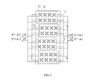
図2は、本発明の実施形態に従うアンテナアレイの概略的な構造図である。図2に示されるように、アンテナアレイは、
垂直方向に配置され、それぞれが複数の放射素子を含む少なくとも2つのアンテナサブアレイを含み、
垂直方向の少なくとも2つの隣接するアンテナサブアレイにおいて、各アンテナサブアレイの対応する位置における放射素子は水平方向に互い違いに配置されている。
FIG. 2 is a schematic structural diagram of an antenna array according to an embodiment of the present invention. As shown in FIG. 2, the antenna array is
Including at least two antenna subarrays arranged vertically and each including a plurality of radiating elements;
In at least two adjacent antenna sub-arrays in the vertical direction, the radiating elements at corresponding positions in each antenna sub-array are staggered in the horizontal direction.
本発明のこの実施形態において提供されるアンテナアレイは、例えば、図2に示されるようにデュアルビームアンテナアレイなどの複数ビームのアンテナアレイを含みうる。例えば、アンテナサブアレイは平行に配置されてもよい。アンテナアレイ内に3つ以上のアンテナサブアレイが垂直方向に配置されるような実装例においては、アンテナサブアレイは等しい間隔で配置されてもよい。 The antenna array provided in this embodiment of the invention may include a multi-beam antenna array such as, for example, a dual beam antenna array as shown in FIG. For example, the antenna subarrays may be arranged in parallel. In implementations in which more than two antenna subarrays are arranged vertically in the antenna array, the antenna subarrays may be arranged at equal intervals.
図2に示されるアンテナアレイは垂直方向に4つのアンテナサブアレイ、すなわち、アンテナサブアレイ1、アンテナサブアレイ2、アンテナサブアレイ3及びアンテナサブアレイ4を含む。この実施形態において提供されるアンテナアレイは、アンテナサブアレイのそれぞれが2行4列の放射素子を含む図2の例を取ることによって示される。本発明のこの実施形態において提供されるアンテナアレイにおいて、各アンテナサブアレイに含まれる放射素子の行の数及び/または列の数は異なるものであってもよいことは理解されるであろう。
The antenna array shown in FIG. 2 includes four antenna subarrays in the vertical direction, that is, antenna subarray 1, antenna subarray 2, antenna subarray 3, and
本発明のこの実施形態において提供されるアンテナアレイ内の垂直方向における少なくとも2つの隣接するアンテナサブアレイにおいて、各アンテナサブアレイにおける対応する位置の放射素子は水平方向に互い違いに配置されてもよく、それによってアンテナアレイパターンにおける水平方向のサイドローブのエネルギーを低減し、各アンテナサブアレイのパターンの合成後の水平方向のサイドローブのエネルギーを打ち消す。各アンテナサブアレイにおける対応する位置の放射素子は、各アンテナサブアレイの同じ行番号及び同じ列番号の放射素子を指す。 In at least two adjacent antenna subarrays in the vertical direction within the antenna array provided in this embodiment of the present invention, the radiating elements at corresponding positions in each antenna subarray may be staggered in the horizontal direction, thereby The energy of the horizontal side lobe in the antenna array pattern is reduced, and the energy of the horizontal side lobe after combining the patterns of the antenna subarrays is canceled. A radiating element at a corresponding position in each antenna subarray refers to a radiating element having the same row number and the same column number of each antenna subarray.
例えば、図2に示されるアンテナアレイにおいて、上から見下ろす方向に、第1のアンテナサブアレイ1の第1行第1列の放射素子11及び第2のアンテナサブアレイ2の第1行第1列の放射素子21は対応する位置にある2つの放射素子である。図2からは、第2のアンテナサブアレイ2における第1行第1列の放射素子21及び第1のアンテナサブアレイ1の第1行第1列の放射素子11が垂直方向に位置合わせされておらず、第2のアンテナサブアレイ2の第1行第1列の放射素子21が第1のアンテナサブアレイ1の第1行第1列の放射素子11から所定の距離だけ水平方向に右側に互い違いに配置されていることが分かる。
For example, in the antenna array shown in FIG. 2, the radiation of the first row and first column of the
他の実施可能な実施形態として、第2のアンテナサブアレイ2の第1行第1列の放射素子21は、第1のアンテナサブアレイ1の第1行第1列の放射素子11から所定の距離だけ水平方向に左側に互い違いに配置されてもよいことは理解されるであろう。
As another possible embodiment, the
代替的に、垂直方向における少なくとも2つの隣接するアンテナサブアレイにおいて、1つのアンテナサブアレイにおける少なくとも1つの放射素子は、垂直方向において、他のアンテナサブアレイの2つの放射素子の間に配置されてもよい。例えば、図2に示されるアンテナアレイにおいて、上から見て、第2のアンテナサブアレイ2の第1行第1列の放射素子21は、垂直方向において、第1のアンテナサブアレイ1の第1行第1列の放射素子11と第1行第2列の放射素子12との間に位置する。
Alternatively, in at least two adjacent antenna subarrays in the vertical direction, at least one radiating element in one antenna subarray may be disposed between two radiating elements in the other antenna subarray in the vertical direction. For example, in the antenna array shown in FIG. 2, when viewed from above, the
代替的に、垂直方向の少なくとも2つの隣接するアンテナサブアレイにおいて、1つのアンテナサブアレイの少なくとも1つの放射素子は、垂直方向において、他のアンテナサブアレイにおける2つの放射素子の中心線に配置されてもよい。例えば、図2に示されるアンテナアレイにおいて、上から見て、第2のアンテナサブアレイ2の第1行第1列の放射素子21は、垂直方向において、第1のアンテナアレイ1の第1行第1列の放射素子11及び第1行第2列の放射素子12の中心線に位置する。図3に示されるように、上から見て、第2のアンテナサブアレイ2の第1行第1列の放射素子21及び第1のアンテナサブアレイ1の第1行第1列の放射素子11の延長線の間の垂直方向の距離X3は、第1のアンテナサブアレイの第1行第1列の放射素子11と第1行第2列の放射素子12との間の間隔X1の半分に等しい。
Alternatively, in at least two adjacent antenna sub-arrays in the vertical direction, at least one radiating element in one antenna sub-array may be arranged in the vertical direction at the center line of two radiating elements in the other antenna sub-array. . For example, in the antenna array shown in FIG. 2, when viewed from above, the
前述の構成を通して、各サブアンテナアレイのパターンの合成後の水平方向のサイドローブのエネルギーは打ち消され、それによってアンテナアレイの超高帯域性能を改善し、通信システムの容量を向上させる。 Through the above-described configuration, the energy of the horizontal sidelobe after the synthesis of the patterns of each sub-antenna array is canceled, thereby improving the ultra-high band performance of the antenna array and increasing the capacity of the communication system.
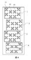
図4は本発明の他の実施形態に従うアンテナアレイの概略的な構造図である。図4に示されるように、前述の実施形態に基づき、代替的に、アンテナアレイの少なくとも1つのアンテナサブアレイにおいて、水平方向の少なくとも2つの隣接する放射素子が垂直方向において互い違いに配置されてもよい。 FIG. 4 is a schematic structural diagram of an antenna array according to another embodiment of the present invention. As shown in FIG. 4, based on the previous embodiments, alternatively, in at least one antenna sub-array of the antenna array, at least two adjacent radiating elements in the horizontal direction may be staggered in the vertical direction. .
図4に示されたアンテナアレイにおいて、上から下を見た方向の第1のアンテナサブアレイ1では、第1行第2列の放射素子12が第1行第1列の放射素子11から所定の距離だけ垂直方向下側に互い違いに配置され、第1行第3列の放射素子13とは垂直方向に互い違いに配置されず、水平方向において第1行第3列の放射素子13と整列している。
In the antenna array shown in FIG. 4, in the
図5に示されたアンテナアレイにおいて、上から下を見た方向の第1のアンテナサブアレイ1では、第1行第2列の放射素子12が第1行第1列の放射素子11から所定の距離だけ垂直方向下方に互い違いに配置され、第1行第3列の放射素子13から所定の距離だけ垂直方向下方にさらに互い違いに配置される。
In the antenna array shown in FIG. 5, in the
図4及び図5においてアンテナサブアレイのそれぞれが2行4列の放射素子を含み、これは、この実施形態に提供されるアンテナアレイを例示するための例として取られていることに注意すべきである。この実施形態において提供されたアンテナアレイでは、各アンテナサブアレイに含まれる放射素子の行の数及び/または列の数は異なるものであってもよい。 It should be noted that each of the antenna sub-arrays in FIGS. 4 and 5 includes a 2 × 4 radiating element, which is taken as an example to illustrate the antenna array provided in this embodiment. is there. In the antenna array provided in this embodiment, the number of rows and / or columns of radiating elements included in each antenna sub-array may be different.
代替的に、少なくとも1つのアンテナサブアレイにおいて、少なくとも1つの放射素子は、水平方向において、垂直方向の2つの隣接する放射素子間に位置してもよい。例えば、図5に示されたアンテナアレイにおいて、上から下を見た方向の第1のアンテナサブアレイ1において、第1行第2列の放射素子12は、水平方向において、第1行第1列の放射素子11と第2行第1列の放射素子15との間に位置する。
Alternatively, in at least one antenna sub-array, at least one radiating element may be located in the horizontal direction between two adjacent radiating elements in the vertical direction. For example, in the antenna array shown in FIG. 5, in the
代替的に、少なくとも1つのアンテナサブアレイにおいて、少なくとも1つの放射素子が、水平方向において、垂直方向の2つの隣接する放射素子の中心線に位置してもよい。例えば、図5に示されたアンテナアレイにおいて、上から下を見た方向の第1のアンテナサブアレイ1において、第1行第2列の放射素子12は、水平方向において、第1行第1列の放射素子11及び第2行第1列の放射素子15の中心線に位置する。
Alternatively, in at least one antenna sub-array, at least one radiating element may be located in the horizontal direction at the center line of two adjacent radiating elements in the vertical direction. For example, in the antenna array shown in FIG. 5, in the
前述の構成を通して、アンテナアレイパターンの水平方向のサイドローブのエネルギーが低減されることに基づき、各アンテナサブアレイのパターンの合成後の垂直ファーサイドローブのエネルギーが打ち消され、それによりアンテナアレイの超高帯域性能を改善し、通信システムの容量を向上しうる。 Through the configuration described above, the energy of the horizontal side lobe of the antenna array pattern is reduced, so that the energy of the vertical far side lobe after the synthesis of the pattern of each antenna subarray is canceled, thereby increasing the antenna array's ultra-high energy. The bandwidth performance can be improved and the capacity of the communication system can be improved.
前述の実施形態に基づき、代替的に、垂直に上から下に見た方向の隣接するアンテナサブアレイが代替的に異なる水平方向に互い違いに配置されてもよい。例えば図2から図5に示されるアンテナアレイにおいて、垂直に上から下に見た方向の隣接するアンテナサブアレイの第1のグループ、すなわちアンテナサブアレイ1及びアンテナサブアレイ2において、第2のアンテナサブアレイ2はアンテナサブアレイ1から水平方向右側に互い違いに配置される。垂直に上から下に見た方向の隣接するアンテナサブアレイの第2のグループ、すなわちアンテナサブアレイ2及びアンテナサブアレイ3において、アンテナサブアレイ3はアンテナサブアレイ2から水平方向左側に互い違いに位置する。
Based on the foregoing embodiments, alternatively, adjacent antenna sub-arrays in a vertically viewed direction from top to bottom may alternatively be staggered in different horizontal directions. For example, in the antenna arrays shown in FIGS. 2 to 5, in the first group of adjacent antenna subarrays in the vertical direction seen from top to bottom, ie,
前述の実施形態に基づき、代替的に、少なくとも1つのアンテナサブアレイの隣接する放射素子間の間隔は垂直方向に前述のアンテナサブアレイと隣接する他のアンテナサブアレイの隣接する放射素子間の間隔に等しくてもよい。例えば、図3に示されるアンテナアレイにおいて、垂直に上から下に見た方向において、第1のアンテナサブアレイ1の隣接する放射素子間の間隔がX1であり、第2のアンテナサブアレイ2の隣接する放射素子間の間隔がX2であると仮定すると、X1=X2として設定してもよい。
Based on the previous embodiment, alternatively, the spacing between adjacent radiating elements of at least one antenna subarray is equal to the spacing between adjacent radiating elements of the other antenna subarray adjacent to the antenna subarray in the vertical direction. Also good. For example, in the antenna array shown in FIG. 3, the distance between adjacent radiating elements of the
アンテナアレイパターンにおいて、代替的に、45°の位相差が少なくとも1つのアンテナサブアレイの放射素子に入力される信号と、垂直方向に前述のアンテナサブアレイと隣接する他のアンテナサブアレイの対応する位置における放射素子に入力される信号との間に存在してもよく、それにより垂直ファーサイドローブをさらに低減する。図6に示されるように、垂直に上から下に見た方向に、第3のアンテナサブアレイ3の第2行第1列の放射素子35に入力される信号の位相は+90°であり、第4のアンテナサブアレイ4の第2行第1列の放射素子45に入力される信号の位相は+45°である。第3のアンテナサブアレイ3の第2行第2列の放射素子36に入力される信号の位相は0°であり、第3のアンテナサブアレイ3における第2行第2列の放射素子36に入力される信号の位相は0°であり、第4のアンテナサブアレイ4の第2行第2列の放射素子46に入力される信号の位相は−45°である。
In the antenna array pattern, alternatively, a signal with a 45 ° phase difference input to the radiating elements of at least one antenna sub-array and radiation at corresponding positions of other antenna sub-arrays adjacent to said antenna sub-array in the vertical direction. May be present between signals input to the element, thereby further reducing the vertical far side lobe. As shown in FIG. 6, the phase of the signal input to the radiating
代替的に、少なくとも1つのアンテナサブアレイにおいて、同一の列に位置する放射素子は電気的に接続されていてもよく、及び/または同一の行に位置する放射素子は電気的に接続されてもよく、それによってアンテナアレイのフィーダー接続を簡略化できる。図7は、アンテナサブアレイ1、アンテナサブアレイ2、アンテナサブアレイ3及びアンテナサブアレイ4の同一の列の放射素子が電気的に接続される実装例を示している。
Alternatively, in at least one antenna sub-array, radiating elements located in the same column may be electrically connected and / or radiating elements located in the same row may be electrically connected. Thereby, the feeder connection of the antenna array can be simplified. FIG. 7 shows an implementation example in which the radiating elements in the same column of the
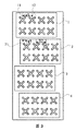
実行可能な実装例として、本発明のこの実施形態で提供されるアンテナアレイの各アンテナサブアレイにおいて、各行の放射素子の数は等しくてもよく、各列の放射素子の数もまた等しくてよい。図2から図7は、アンテナサブアレイ1、アンテナサブアレイ2、アンテナサブアレイ3及びアンテナサブアレイ4の全てが2行4列の放射素子を含む実装例を示している。他の例に関して、図8は、アンテナサブアレイ1からアンテナサブアレイ6の全てが1行4列の放射素子を含む実装例を示している。
As a possible implementation, in each antenna sub-array of the antenna array provided in this embodiment of the invention, the number of radiating elements in each row may be equal and the number of radiating elements in each column may also be equal. 2 to 7 show an implementation example in which the
他の実施可能な実装例として、本発明の実施形態で提供されるアンテナアレイとして、少なくとも2つのアンテナサブアレイが少なくとも2つの種類のアンテナサブアレイを含んでもよく、各種類のアンテナアレイはm行n列の放射素子を含んでもよく、異なるアンテナサブアレイにおけるm及び/またはnは等しくなくてもよく、m及びnは共に1よりも大きな整数である。例えば、図9に示されるアンテナアレイは、2つの種類のアンテナサブアレイを含み、アンテナサブアレイ1及びアンテナサブアレイ3は同一の種類のアンテナサブアレイであり、1行4列の放射素子を含み、アンテナサブアレイ2及びアンテナサブアレイ4は別の種類のアンテナサブアレイであり、2行4列の放射素子を含む。
As another possible implementation, as an antenna array provided in an embodiment of the present invention, at least two antenna sub-arrays may include at least two types of antenna sub-arrays, each type of antenna array having m rows and n columns. , And m and / or n in different antenna sub-arrays may not be equal, and m and n are both integers greater than one. For example, the antenna array shown in FIG. 9 includes two types of antenna sub-arrays, and the
代替的に、少なくとも2つの種類のアンテナサブアレイは交互に垂直方向に配置されてもよい。図9に示されたように、垂直に上から下に見た方向に、同一の種類のアンテナサブアレイ1及びアンテナサブアレイ3が他の種類のアンテナサブアレイ2及びアンテナサブアレイ4と交互に配置される。
Alternatively, the at least two types of antenna subarrays may be alternately arranged in the vertical direction. As shown in FIG. 9, the same type of
本発明はさらに、実施形態に従うアンテナ装置を提供する。アンテナ装置は、少なくとも1つのアンテナアレイを含みうる。 The present invention further provides an antenna device according to the embodiment. The antenna device may include at least one antenna array.
アンテナアレイは、少なくとも2つのアンテナサブアレイを含み、少なくとも2つのアンテナサブアレイは垂直方向に配置され、各アンテナサブアレイは複数の放射素子を含み、垂直方向の少なくとも2つの隣接するアンテナサブアレイにおいて、各アンテナサブアレイの対応する位置の放射素子は水平方向に互い違いに配置される。 The antenna array includes at least two antenna sub-arrays, the at least two antenna sub-arrays are arranged in a vertical direction, each antenna sub-array includes a plurality of radiating elements, and each antenna sub-array in at least two adjacent antenna sub-arrays in the vertical direction. The corresponding radiating elements are alternately arranged in the horizontal direction.
アンテナ装置は、アンテナアレイによって送信される信号の位相及び強度を調整するように構成されたビーム形成ネットワークを含んでもよい。例えば、アンテナアレイが2種類のアンテナサブアレイを含む実装例において、2つのビーム形成ネットワークがアンテナ装置内に構成されてもよい。1つのビーム形成ネットワークは1つの種類のアンテナサブアレイに供給してこの種類のアンテナサブアレイによって送信される信号の位相及び強度を調整し、それによって、アンテナサブアレイによって送信される信号が所定の強度及び位相を持つことを可能にする。さらに、他のビーム形成ネットワークが他の種類のアンテナサブアレイに供給してこの種類のアンテナサブアレイによって送信される信号の位相及び強度を調整してもよく、それによってアンテナサブアレイによって送信される信号が所定の強度及び位相を有することを可能とする。これら2つのビーム形成ネットワークは、パワースプリッターまたは位相シフターのようなデバイスを通して接続されてもよい。アンテナアレイの具体的な構造及び機能に関しては、本発明において提供されるアンテナアレイの実施形態を参照しうる。従って、本明細書では更なる詳細は提供されない。 The antenna device may include a beam forming network configured to adjust the phase and intensity of signals transmitted by the antenna array. For example, in an implementation example in which the antenna array includes two types of antenna sub-arrays, two beam forming networks may be configured in the antenna device. One beamforming network feeds one type of antenna subarray to adjust the phase and strength of the signal transmitted by this type of antenna subarray so that the signal transmitted by the antenna subarray has a predetermined strength and phase. Makes it possible to have In addition, other beamforming networks may supply other types of antenna subarrays to adjust the phase and strength of signals transmitted by this type of antenna subarrays, so that the signals transmitted by the antenna subarrays are predetermined. It is possible to have the intensity and phase of These two beam forming networks may be connected through a device such as a power splitter or phase shifter. For the specific structure and function of the antenna array, reference may be made to the antenna array embodiments provided in the present invention. Accordingly, no further details are provided herein.
図10は実施形態に従うアンテナ装置の概略的な構造図である。図10に示されるように、アンテナ装置は複数のアンテナアレイAを含み、その間に少なくとも1つのインバータアレイが含まれてもよい。インバータアレイの供給位相は他のどのアンテナアレイAの供給位相に対しても反対である。インバータアレイは送信される信号の位相に関して反転処理を行い、インバータアレイ及びビーム形成ネットワークBは共にインバータアレイによって送信される信号が所定の位相を有することを可能とする。図11は、図10に示されたアンテナ装置のビーム形成ネットワークの概略的な構造図であり、図12は図10に示されたアンテナ装置の他のビーム形成ネットワークの概略的な構造図である。図11及び図12に示されるビーム形成ネットワークの構造は、ともに既存の構造であり、その原理は本明細書で再度説明しない。 FIG. 10 is a schematic structural diagram of the antenna device according to the embodiment. As shown in FIG. 10, the antenna device may include a plurality of antenna arrays A, and at least one inverter array may be included therebetween. The supply phase of the inverter array is opposite to the supply phase of any other antenna array A. The inverter array inverts the phase of the transmitted signal, and both the inverter array and the beam forming network B allow the signal transmitted by the inverter array to have a predetermined phase. 11 is a schematic structural diagram of the beam forming network of the antenna device shown in FIG. 10, and FIG. 12 is a schematic structural diagram of another beam forming network of the antenna device shown in FIG. . The structure of the beam forming network shown in FIGS. 11 and 12 is an existing structure, and its principle will not be described again in this specification.
本発明のこの実施形態において提供されるアンテナ装置によれば、アンテナアレイの垂直方向の少なくとも2つの隣接するアンテナサブアレイにおいて、各アンテナサブアレイの対応する位置の放射素子は水平方向に互い違いに配置される。このことは、アンテナアレイパターンの水平方向のサイドローブのエネルギーを低減し、超広域性能を改善し、通信システムの容量を向上させる。 According to the antenna device provided in this embodiment of the present invention, in at least two adjacent antenna sub-arrays in the vertical direction of the antenna array, the radiating elements at corresponding positions in each antenna sub-array are staggered in the horizontal direction. . This reduces the horizontal sidelobe energy of the antenna array pattern, improves ultra-wide area performance, and increases the capacity of the communication system.
本発明はさらに、アンテナ装置を含む実施形態に従う基地局を提供する。 The present invention further provides a base station according to an embodiment including an antenna device.
アンテナ装置は、少なくとも1つのアンテナアレイを含んでもよい。 The antenna device may include at least one antenna array.
アンテナアレイは、少なくとも2つのアンテナサブアレイを含み、少なくとも2つのアンテナサブアレイは垂直方向に配置され、各アンテナサブアレイは複数の放射素子を含み、垂直方向の少なくとも2つの隣接するアンテナサブアレイにおいて、各アンテナサブアレイの対応する位置の放射素子は水平方向に互い違いに配置される。 The antenna array includes at least two antenna sub-arrays, the at least two antenna sub-arrays are arranged in a vertical direction, each antenna sub-array includes a plurality of radiating elements, and each antenna sub-array in at least two adjacent antenna sub-arrays in the vertical direction. The corresponding radiating elements are alternately arranged in the horizontal direction.
図13は、本発明の実施形態に従う基地局の概略的な構造図である。図13に示されるように、基地局のアンテナ装置は、少なくとも1つのアンテナアレイAと、少なくとも1つのビーム形成ネットワークBと、少なくとも1つの位相シフターCと、を含み、
ビーム形成ネットワークBはアンテナアレイによって送信される信号の位相及び強度を調整するように構成され、
位相シフターCはアンテナ装置のダウンチルト角度を調整するように構成される。
FIG. 13 is a schematic structural diagram of a base station according to an embodiment of the present invention. As shown in FIG. 13, the antenna apparatus of the base station includes at least one antenna array A, at least one beam forming network B, and at least one phase shifter C.
The beam forming network B is configured to adjust the phase and intensity of signals transmitted by the antenna array;
The phase shifter C is configured to adjust the down tilt angle of the antenna device.
本発明のこの実施形態において提供される基地局によれば、アンテナアレイの垂直方向の少なくとも2つの隣接するアンテナサブアレイにおいて、各アンテナサブアレイの対応する位置の放射素子は水平方向に互い違いに配置される。このことは、アンテナアレイパターンの水平方向のサイドローブのエネルギーを低減し、超高帯域性能を改善し、通信システムの容量を向上させる。 According to the base station provided in this embodiment of the invention, in at least two adjacent antenna sub-arrays in the vertical direction of the antenna array, the radiating elements at corresponding positions in each antenna sub-array are staggered in the horizontal direction. . This reduces the horizontal sidelobe energy of the antenna array pattern, improves ultra-high bandwidth performance, and increases the capacity of the communication system.
使用者数の増大に伴い、通信システムはシステム容量を拡大するために基地局を追加する必要があり、例えば6セクターネットワーク構成が、基地局を追加することなくシステム容量を拡張するために使用されてもよく、システム容量を拡大するためには複数ビームアンテナを採用することが好適な方法である。本発明の実施形態において提供されるアンテナアレイ及びアンテナ装置は複数ビーム用途に適用可能であり、本発明の実施形態において提供される基地局のアンテナ装置は複数ビーム用途に適用可能である。図14に示されるような既存の複数ビームアンテナアレイのパターンと比較して、図15に示されるような本発明で提供されるアンテナアレイのパターンは水平方向のサイドローブのエネルギーが低い。 As the number of users increases, the communication system needs to add base stations to expand system capacity, for example, a 6 sector network configuration is used to expand system capacity without adding base stations. In order to expand the system capacity, it is preferable to employ a multiple beam antenna. The antenna array and the antenna device provided in the embodiment of the present invention can be applied to a multi-beam application, and the antenna device of the base station provided in the embodiment of the present invention can be applied to a multi-beam application. Compared with the pattern of the existing multi-beam antenna array as shown in FIG. 14, the pattern of the antenna array provided by the present invention as shown in FIG. 15 has lower energy of the horizontal side lobe.
最後に、上述の実施形態は単に本発明の技術的解決手段を説明するために提供されたにすぎず、本発明を限定することを意図するものではないことに注意すべきである。本発明が実施形態を参照して詳細に説明されたが、対応する技術的解決手段の本質を本発明の範囲から逸脱させることのない限り、実施形態で説明された技術的解決手段に改良がなされてもよく、技術的解決手段のいくつかの技術的特徴に対して等価な置換がなされてもよいことは当業者であれば理解するであろう。 Finally, it should be noted that the above-described embodiments are merely provided to illustrate the technical solutions of the present invention and are not intended to limit the present invention. While the invention has been described in detail with reference to the embodiment, unless it is departing from the essence of corresponding technical solutions from the scope of the present invention, improved technical solution described in the embodiment Those skilled in the art will appreciate that may be made and equivalent substitutions may be made for some technical features of the technical solutions.
1、2、3、4 アンテナサブアレイ
11、12、13、15、21、35、36 放射素子
A アンテナアレイ
B ビーム形成ネットワーク
C 位相シフター
1, 2, 3, 4
Claims (13)
少なくとも2つの前記アンテナサブアレイ(1)が垂直方向に配置され、前記アンテナサブアレイ(1)のそれぞれが複数の放射素子を含み、
垂直方向の少なくとも2つの隣接する前記アンテナサブアレイ(1)において、前記アンテナサブアレイ(1)のそれぞれの対応する位置における前記放射素子が水平方向に互い違いに配置され、
少なくとも1つの前記アンテナサブアレイの放射素子に入力される信号と、垂直方向に前記アンテナサブアレイに隣接する他の前記アンテナサブアレイの対応する位置の放射素子に入力される信号との間に、45°の位相差が存在する、アンテナアレイ。 An antenna array comprising at least two antenna subarrays (1),
At least two of the antenna subarrays (1) are arranged vertically, each of the antenna subarrays (1) comprising a plurality of radiating elements;
In at least two adjacent antenna subarrays (1) in the vertical direction, the radiating elements at respective corresponding positions of the antenna subarray (1) are staggered in the horizontal direction ;
45 ° between a signal input to a radiating element of at least one of the antenna subarrays and a signal input to a radiating element of a corresponding position of another antenna subarray adjacent to the antenna subarray in the vertical direction. An antenna array where there is a phase difference .
Applications Claiming Priority (1)
| Application Number | Priority Date | Filing Date | Title |
|---|---|---|---|
| PCT/CN2012/076278 WO2012126439A2 (en) | 2012-05-30 | 2012-05-30 | Antenna array, antenna device and base station |
Publications (2)
| Publication Number | Publication Date |
|---|---|
| JP2015521441A JP2015521441A (en) | 2015-07-27 |
| JP5969698B2 true JP5969698B2 (en) | 2016-08-17 |
Family
ID=46879814
Family Applications (1)
| Application Number | Title | Priority Date | Filing Date |
|---|---|---|---|
| JP2015514315A Active JP5969698B2 (en) | 2012-05-30 | 2012-05-30 | Antenna array, antenna device, and base station |
Country Status (5)
| Country | Link |
|---|---|
| US (1) | US10181657B2 (en) |
| EP (1) | EP2846400B1 (en) |
| JP (1) | JP5969698B2 (en) |
| CN (1) | CN102859789B (en) |
| WO (1) | WO2012126439A2 (en) |
Families Citing this family (22)
| Publication number | Priority date | Publication date | Assignee | Title |
|---|---|---|---|---|
| EP2359438B1 (en) | 2008-11-20 | 2019-07-17 | CommScope Technologies LLC | Dual-beam sector antenna and array |
| JP6039597B2 (en) * | 2014-02-25 | 2016-12-07 | 日本電信電話株式会社 | Antenna, base station apparatus, and antenna element arrangement method |
| JP6409676B2 (en) * | 2014-06-03 | 2018-10-24 | 三菱電機株式会社 | Array antenna and antenna for satellite communication |
| US10263331B2 (en) | 2014-10-06 | 2019-04-16 | Kymeta Corporation | Device, system and method to mitigate side lobes with an antenna array |
| JP6396244B2 (en) | 2015-03-25 | 2018-09-26 | パナソニック株式会社 | Radar equipment |
| CN105356062B (en) * | 2015-10-23 | 2021-06-18 | 广东博纬通信科技有限公司 | Broadband array antenna |
| JP6555358B2 (en) | 2015-11-27 | 2019-08-07 | 日立金属株式会社 | Antenna device |
| WO2018094660A1 (en) * | 2016-11-24 | 2018-05-31 | 深圳市大疆创新科技有限公司 | Antenna assembly and unmanned aerial vehicle |
| US10381811B2 (en) * | 2017-03-29 | 2019-08-13 | Hubbell Incorporated | Utility conduit system |
| WO2018176361A1 (en) * | 2017-03-31 | 2018-10-04 | 华为技术有限公司 | Antenna downtilt adjusting apparatus and communications device |
| WO2019044274A1 (en) * | 2017-08-30 | 2019-03-07 | 株式会社村田製作所 | Antenna module |
| CN107959125B (en) * | 2017-11-17 | 2020-10-20 | 深圳市盛路物联通讯技术有限公司 | Array antenna and wireless communication device |
| CN110071373B (en) * | 2018-03-12 | 2023-03-14 | 京信通信技术(广州)有限公司 | Multi-system integrated antenna |
| US10561029B1 (en) * | 2019-04-10 | 2020-02-11 | Innolux Corporation | Electronic device |
| US11181614B2 (en) * | 2019-06-06 | 2021-11-23 | GM Global Technology Operations LLC | Antenna array tilt and processing to eliminate false detections in a radar system |
| CN113629379A (en) * | 2020-05-09 | 2021-11-09 | 康普技术有限责任公司 | Dual beam antenna array |
| CN111864406A (en) * | 2020-07-29 | 2020-10-30 | 江苏泰科微通讯科技有限公司 | Miniaturized four-low-frequency multi-port base station antenna |
| US11418975B2 (en) * | 2020-10-14 | 2022-08-16 | Commscope Technologies Llc | Base station antennas with sector splitting in the elevation plan based on frequency band |
| WO2022160163A1 (en) * | 2021-01-28 | 2022-08-04 | Telefonaktiebolaget Lm Ericsson (Publ) | Antenna system, rf communication device, and method of operating the same |
| CN113013583B (en) * | 2021-01-29 | 2023-08-18 | 中国电子科技集团公司第三十八研究所 | Millimeter wave radar packaging module |
| CN117480685A (en) * | 2021-06-15 | 2024-01-30 | 瑞典爱立信有限公司 | Advanced antenna system with reduced sidelobes |
| CN114447585B (en) * | 2022-01-29 | 2024-03-19 | 京东方科技集团股份有限公司 | Multi-beam antenna, manufacturing method thereof and communication device |
Family Cites Families (20)
| Publication number | Priority date | Publication date | Assignee | Title |
|---|---|---|---|---|
| US4423421A (en) * | 1979-11-26 | 1983-12-27 | Raytheon Company | Slot array antenna with amplitude taper across a small circular aperture |
| SE449540B (en) * | 1985-10-31 | 1987-05-04 | Ericsson Telefon Ab L M | LETTER MANAGEMENT FOR AN ELECTRICALLY CONTROLLED RADAR ANTENNA |
| JP3415001B2 (en) * | 1997-09-10 | 2003-06-09 | 三菱電機株式会社 | Array antenna |
| JP3812203B2 (en) * | 1999-02-17 | 2006-08-23 | 三菱電機株式会社 | Waveguide slot array antenna |
| SE518207C2 (en) * | 1999-09-10 | 2002-09-10 | Ericsson Telefon Ab L M | Large group antenna |
| JP4021150B2 (en) * | 2001-01-29 | 2007-12-12 | 沖電気工業株式会社 | Slot array antenna |
| EP1380069B1 (en) * | 2001-04-16 | 2007-06-06 | Fractus, S.A. | Dual-band dual-polarized antenna array |
| JP2005303801A (en) * | 2004-04-14 | 2005-10-27 | Toyota Central Res & Dev Lab Inc | Antenna device |
| CN100369324C (en) * | 2005-05-30 | 2008-02-13 | 东南大学 | Chip integrated waveguide dual-frequency broad-band slot array antenna unit |
| CN100530818C (en) * | 2005-06-08 | 2009-08-19 | 东南大学 | Dielectric substrate integrated waveguide slot array antenna |
| JP4602276B2 (en) * | 2006-03-23 | 2010-12-22 | 三菱電機株式会社 | Waveguide slot array antenna device |
| EP1965462B1 (en) * | 2007-03-02 | 2010-09-01 | Saab Ab | Hull integrated antenna |
| US8237619B2 (en) * | 2007-10-16 | 2012-08-07 | Powerwave Technologies, Inc. | Dual beam sector antenna array with low loss beam forming network |
| CN201134510Y (en) * | 2007-10-31 | 2008-10-15 | 京信通信系统(中国)有限公司 | Minimized intelligent antenna system |
| JP2009159225A (en) * | 2007-12-26 | 2009-07-16 | Samsung Electronics Co Ltd | Antenna device |
| EP2359438B1 (en) | 2008-11-20 | 2019-07-17 | CommScope Technologies LLC | Dual-beam sector antenna and array |
| CN201336371Y (en) * | 2008-12-22 | 2009-10-28 | 东莞市晖速天线技术有限公司 | Staggered-arrangement flat plate directional intelligent antenna array |
| CN201397879Y (en) * | 2009-01-09 | 2010-02-03 | 东莞市晖速天线技术有限公司 | Device used for adjusting electrical downtilt of mobile communication antenna |
| CN201392888Y (en) * | 2009-04-10 | 2010-01-27 | 北京华盛天基通信技术有限公司 | Intelligent dual-polarized antenna |
| JP5620757B2 (en) * | 2010-09-01 | 2014-11-05 | 株式会社豊田中央研究所 | Radar equipment |
-
2012
- 2012-05-30 WO PCT/CN2012/076278 patent/WO2012126439A2/en active Application Filing
- 2012-05-30 JP JP2015514315A patent/JP5969698B2/en active Active
- 2012-05-30 CN CN201280000882.0A patent/CN102859789B/en active Active
- 2012-05-30 EP EP12760991.5A patent/EP2846400B1/en active Active
-
2014
- 2014-11-26 US US14/554,765 patent/US10181657B2/en active Active
Also Published As
| Publication number | Publication date |
|---|---|
| US20150084832A1 (en) | 2015-03-26 |
| EP2846400B1 (en) | 2019-10-09 |
| EP2846400A2 (en) | 2015-03-11 |
| WO2012126439A2 (en) | 2012-09-27 |
| EP2846400A4 (en) | 2015-04-22 |
| WO2012126439A3 (en) | 2013-05-02 |
| US10181657B2 (en) | 2019-01-15 |
| CN102859789B (en) | 2016-04-13 |
| CN102859789A (en) | 2013-01-02 |
| JP2015521441A (en) | 2015-07-27 |
Similar Documents
| Publication | Publication Date | Title |
|---|---|---|
| JP5969698B2 (en) | Antenna array, antenna device, and base station | |
| US11469497B2 (en) | Dual-beam sector antenna and array | |
| CN108432088B (en) | Phased array antenna with sub-arrays | |
| CN106469854B (en) | Microwave millimeter wave dual-frequency antenna | |
| CN105356062B (en) | Broadband array antenna | |
| KR101672502B1 (en) | Dual-polarized, omnidirectional antenna | |
| US20170207545A1 (en) | Overlapping Linear Sub-Array for Phased Array Antennas | |
| CN106252901B (en) | Broadband three-beam array antenna | |
| EP3379648B1 (en) | Planar array antenna and communication device | |
| KR101918138B1 (en) | Cellular array with adjustable spotlight beam | |
| WO2015139294A1 (en) | Array antenna | |
| AU2014213078A1 (en) | An antenna arrangement and a base station | |
| EP3231037B1 (en) | High coverage antenna array and method using grating lobe layers | |
| WO2013067790A1 (en) | Mono-polarized 22-beam aerial for mobile communication base station | |
| WO2018040140A1 (en) | Broadband five-beam array antenna | |
| CN106252903A (en) | A kind of double frequency two beam antenna array and double frequency two beam antenna | |
| AU2014211633A1 (en) | An antenna arrangement and a base station | |
| CN107359424B (en) | Array antenna | |
| JP5647334B2 (en) | Planar array antenna with reduced beam width | |
| US10454164B2 (en) | Antenna device | |
| CN110994203B (en) | Broadband mixed multi-beam array antenna | |
| CN206040986U (en) | Two beam antenna arrays of dual -frenquency and two beam antenna of dual -frenquency | |
| WO2019184008A1 (en) | Broadband nine-beam array antenna | |
| CN108767498A (en) | A kind of multisystem antenna for base station of controllable beam angle |
Legal Events
| Date | Code | Title | Description |
|---|---|---|---|
| A131 | Notification of reasons for refusal |
Free format text: JAPANESE INTERMEDIATE CODE: A131 Effective date: 20151201 |
|
| A521 | Request for written amendment filed |
Free format text: JAPANESE INTERMEDIATE CODE: A523 Effective date: 20160301 |
|
| TRDD | Decision of grant or rejection written | ||
| A01 | Written decision to grant a patent or to grant a registration (utility model) |
Free format text: JAPANESE INTERMEDIATE CODE: A01 Effective date: 20160607 |
|
| A61 | First payment of annual fees (during grant procedure) |
Free format text: JAPANESE INTERMEDIATE CODE: A61 Effective date: 20160707 |
|
| R150 | Certificate of patent or registration of utility model |
Ref document number: 5969698 Country of ref document: JP Free format text: JAPANESE INTERMEDIATE CODE: R150 |
|
| R250 | Receipt of annual fees |
Free format text: JAPANESE INTERMEDIATE CODE: R250 |
|
| R250 | Receipt of annual fees |
Free format text: JAPANESE INTERMEDIATE CODE: R250 |
|
| R250 | Receipt of annual fees |
Free format text: JAPANESE INTERMEDIATE CODE: R250 |
|
| R250 | Receipt of annual fees |
Free format text: JAPANESE INTERMEDIATE CODE: R250 |
|
| R250 | Receipt of annual fees |
Free format text: JAPANESE INTERMEDIATE CODE: R250 |