JP5967865B2 - IMAGING DEVICE, IMAGING DEVICE CONTROL METHOD, AND PROGRAM - Google Patents
IMAGING DEVICE, IMAGING DEVICE CONTROL METHOD, AND PROGRAM Download PDFInfo
- Publication number
- JP5967865B2 JP5967865B2 JP2011082165A JP2011082165A JP5967865B2 JP 5967865 B2 JP5967865 B2 JP 5967865B2 JP 2011082165 A JP2011082165 A JP 2011082165A JP 2011082165 A JP2011082165 A JP 2011082165A JP 5967865 B2 JP5967865 B2 JP 5967865B2
- Authority
- JP
- Japan
- Prior art keywords
- live view
- value
- change mode
- shutter speed
- electronic shutter
- Prior art date
- Legal status (The legal status is an assumption and is not a legal conclusion. Google has not performed a legal analysis and makes no representation as to the accuracy of the status listed.)
- Expired - Fee Related
Links
Images


Classifications
-
- H—ELECTRICITY
- H04—ELECTRIC COMMUNICATION TECHNIQUE
- H04N—PICTORIAL COMMUNICATION, e.g. TELEVISION
- H04N23/00—Cameras or camera modules comprising electronic image sensors; Control thereof
- H04N23/60—Control of cameras or camera modules
- H04N23/63—Control of cameras or camera modules by using electronic viewfinders
- H04N23/631—Graphical user interfaces [GUI] specially adapted for controlling image capture or setting capture parameters
-
- H—ELECTRICITY
- H04—ELECTRIC COMMUNICATION TECHNIQUE
- H04N—PICTORIAL COMMUNICATION, e.g. TELEVISION
- H04N23/00—Cameras or camera modules comprising electronic image sensors; Control thereof
- H04N23/60—Control of cameras or camera modules
- H04N23/667—Camera operation mode switching, e.g. between still and video, sport and normal or high- and low-resolution modes
-
- H—ELECTRICITY
- H04—ELECTRIC COMMUNICATION TECHNIQUE
- H04N—PICTORIAL COMMUNICATION, e.g. TELEVISION
- H04N23/00—Cameras or camera modules comprising electronic image sensors; Control thereof
- H04N23/60—Control of cameras or camera modules
- H04N23/67—Focus control based on electronic image sensor signals
-
- H—ELECTRICITY
- H04—ELECTRIC COMMUNICATION TECHNIQUE
- H04N—PICTORIAL COMMUNICATION, e.g. TELEVISION
- H04N23/00—Cameras or camera modules comprising electronic image sensors; Control thereof
- H04N23/70—Circuitry for compensating brightness variation in the scene
-
- H—ELECTRICITY
- H04—ELECTRIC COMMUNICATION TECHNIQUE
- H04N—PICTORIAL COMMUNICATION, e.g. TELEVISION
- H04N23/00—Cameras or camera modules comprising electronic image sensors; Control thereof
- H04N23/60—Control of cameras or camera modules
- H04N23/63—Control of cameras or camera modules by using electronic viewfinders
- H04N23/633—Control of cameras or camera modules by using electronic viewfinders for displaying additional information relating to control or operation of the camera
Landscapes
- Engineering & Computer Science (AREA)
- Multimedia (AREA)
- Signal Processing (AREA)
- Human Computer Interaction (AREA)
- Studio Devices (AREA)
- Exposure Control For Cameras (AREA)
- Indication In Cameras, And Counting Of Exposures (AREA)
- Automatic Focus Adjustment (AREA)
Description
本発明は、表示部に被写体像を表示するライブビュー機能を有する撮像装置、撮像装置の制御方法及びプログラムに関する。 The present invention relates to an imaging apparatus having a live view function for displaying a subject image on a display unit, an imaging apparatus control method, and a program.
従来、電子スチルカメラには撮影に必要な様々な設定値があり、撮影環境や装着レンズに応じて、それらの設定値を変更する必要がある。また、設定値を変更する場合には、設定値を変更しながら、その変更による効果がユーザに分かるようにすることが望まれる。特にAFキャリブレーション設定、すなわちオートフォーカス時のピントの微妙なずれを補正するピント調整値の変更を行う場合は、その変更の過程を見ながらでないと変更が行いにくい。そこで、変更の効果がユーザに分かるようにするために、設定開始と同時にライブビューを開始する機種が存在している。例えば特許文献2には、AFキャリブレーション撮影シーケンスにおいて、レリーズスイッチ1が押されたならば、位相差AFによるレンズ駆動を行い、ライブビュー表示の開始を行い、イメージャAF(コントラストAF)によるレンズ駆動を行う構成が開示されている([0094]等を参照のこと)。
Conventionally, an electronic still camera has various setting values necessary for shooting, and it is necessary to change these setting values according to the shooting environment and a mounted lens. Further, when changing the set value, it is desirable to make the user understand the effect of the change while changing the set value. In particular, when changing the AF calibration setting, that is, when changing the focus adjustment value for correcting a slight focus shift at the time of autofocus, it is difficult to change without looking at the process of the change. Therefore, in order to make the effect of the change known to the user, there are models that start the live view simultaneously with the start of setting. For example, in
設定開始と同時にライブビューを開始した場合、ライブビューのスルー画像は、ユーザが設定したTv値、Av値、ISO値に従って表示されるため、外的環境によっては最適なライブビューが始まらないことがある。そのときは、まず最適なライブビューになるようにTv値、Av値、ISO値をユーザ自身が設定しなければならなくなり、煩わしい上、その時点においてユーザが設定しているTv値、Av値、ISO値を変更しなければならなくなる。 When the live view is started at the same time as the setting is started, the live view through image is displayed according to the Tv value, Av value, and ISO value set by the user. Therefore, the optimal live view may not start depending on the external environment. is there. At that time, the user must first set the Tv value, Av value, and ISO value so as to obtain an optimal live view, which is bothersome and the Tv value, Av value, The ISO value will have to be changed.
特許文献1では、レリーズボタンが操作されていない押圧解除状態では、フリッカの発生を防止する電子シャッタ速度が低輝度域で用いられる第1のプログラム線図に基づいて、被写体輝度に対して決まる電子シャッタ速度、絞り及び撮影感度を設定し、半押し維持状態では、レリーズボタンの半押し操作に応答して決定される静止画撮影用の絞りに設定し、絞り優先式の第2のプログラム線図に前記静止画撮影用の絞りを適用して、被写体輝度に対して決まる電子シャッタ速度及び撮影感度を設定する構成が開示されている。しかしながら、その場合は逆にレリーズボタンを半押ししない限り、ユーザが設定したTv値、Av値、ISO値を反映した画像が表示されないため、通常撮影時において課題が発生し、やはり煩わしさは解消されない。
In
本発明は上記のような点に鑑みてなされたものであり、設定値の変更を簡易に視覚的に分かりやすく行えるようにすることを目的とする。 The present invention has been made in view of the above points, and an object of the present invention is to make it possible to easily and visually change a set value.
本発明の撮像装置は、ライブビューを伴った、オートフォーカスのピント調整値の変更が可能な変更モードを有する撮像装置であって、表示部に被写体像を表示するライブビューを行う表示制御手段と、被写体の輝度を測光する測光手段と、ユーザが設定した電子シャッタ速度、絞り値、ISO値を保存する保存手段と、ライブビュー開始の前に、前記変更モードへの移行指示の有無を判定し、前記変更モードへの移行指示がなければ、ユーザによって選択された撮影モードに応じて定められる電子シャッタ速度、絞り値、ISO値に従ってライブビューを実行させ、前記変更モードへの移行指示があれば、前記保存手段に保存した電子シャッタ速度、絞り値、ISO値を用いずに、前記測光手段で測光した被写体の輝度に対応して電子シャッタ速度、絞り値、ISO値を決定するプログラム線図でライブビューを実行させる制御手段とを備えたことを特徴とする。 An image pickup apparatus according to the present invention is an image pickup apparatus having a change mode in which an autofocus focus adjustment value can be changed with a live view, and a display control unit that performs a live view for displaying a subject image on a display unit. A metering unit for metering the luminance of the subject, a storage unit for storing the electronic shutter speed, aperture value, and ISO value set by the user, and whether or not there is an instruction to shift to the change mode before starting the live view. If there is no instruction to shift to the change mode, live view is executed in accordance with the electronic shutter speed, aperture value, and ISO value determined according to the shooting mode selected by the user, and if there is an instruction to shift to the change mode. The electronic shutter speed, aperture value, and ISO value stored in the storage unit are not used, and the electronic shutter corresponding to the brightness of the subject measured by the photometry unit is used. Motor speed, aperture value, characterized in that a control means for executing a live view by program diagram for determining the ISO value.
本発明によれば、例えばオートフォーカスのピント調整値の変更時に、ユーザが設定した電子シャッタ速度、絞り値、ISO値を変更することなく、その変更に適したライブビューを表示し、設定値の変更を簡易に視覚的に分かりやすく行えるようになる。 According to the present invention, for example, when changing the focus adjustment value of autofocus, a live view suitable for the change is displayed without changing the electronic shutter speed, aperture value, and ISO value set by the user. Changes can be easily and visually comprehended.
以下、添付図面を参照して、本発明の好適な実施形態について説明する。
図1、図2を参照して、本発明の実施形態に係るライブビュー機能を有する電子スチルカメラの構成を説明する。図1は、本発明の実施形態に係る電子スチルカメラの構成例を示すブロック図である。200はカメラ本体、100はレンズユニットである。なお、レンズユニット100のレンズ5は通常、複数枚のレンズから構成されるが、ここでは簡略して一枚のレンズのみで示している。
Preferred embodiments of the present invention will be described below with reference to the accompanying drawings.
A configuration of an electronic still camera having a live view function according to the embodiment of the present invention will be described with reference to FIGS. FIG. 1 is a block diagram illustrating a configuration example of an electronic still camera according to an embodiment of the present invention.
6はレンズユニット100がカメラ本体200側と通信を行うための通信端子であり、10はカメラ本体200がレンズユニット100側と通信を行うための通信端子である。レンズユニット100は、この通信端子6、10を介してカメラ本体200のマイクロコンピュータ39と通信する。これにより、内部のレンズシステム制御回路4によって絞り駆動回路2を介して絞り1の制御を行い、AF駆動回路3を介してレンズ5の位置を変位させることで焦点を合わせる。
6 is a communication terminal for the
カメラ本体200において、11はAFセンサであり、マイクロコンピュータ39にデフォーカス量を出力し、マイクロコンピュータ39はそれに基づいてレンズユニット100を制御する。15はAEセンサであり、レンズユニット100を通した被写体の輝度を測光する。12はクイックリターンミラーであり、露光の際にマイクロコンピュータ39から指示されて、不図示のアクチュエータによりアップダウンされる。13はフォーカシングスクリーン、14はペンタプリズム、16はファイダである。撮影者は、ペンタプリズム14とファインダ16を介して、フォーカシングスクリーン13を観察することで、レンズユニット100を通して得た被写体の光学像の焦点や構図の確認が可能となる。
In the
17はフォーカルプレーンシャッタであり、マイクロコンピュータ39の制御で撮像素子20の露光時間を自由に制御できる。18は光学フィルタであり、一般的にローパスフィルタ等から構成され、フォーカルプレーンシャッタ17より入ってくる光の高周波成分をカットして、撮像素子20に被写体像を導光する。19は光学フィルタ18に接続されている圧電素子である。20は撮像素子であり、一般的にCCDやCMOS等の撮像素子が用いられ、レンズユニット100を通して撮像素子20上に結像された被写体象を光電変換して電気信号として取り込む。
21はアンプ回路であり、取り込まれた電気信号に対して、設定されている撮影感度に応じたゲインで撮影信号を増幅する。22はA/D変換回路であり、撮像素子20によって電気信号に変換されたアナログ信号をデジタル信号に変換する。23は画像処理回路、24は液晶駆動回路、25は液晶表示部である。画像処理回路23は、A/D変換回路22によってデジタル信号に変換された画像データに対して、フィルタ処理、色変換処理、ガンマー/ニー処理を行い、メモリコントローラ27に出力する。また、画像処理回路23は、D/A変換回路も内蔵しており、A/D変換回路22によってデジタル信号に変換された画像データやメモリコントローラ27により入力される画像データをアナログ信号に変換して液晶駆動回路24を介して液晶表示部25に出力することも可能である。これらの画像処理回路23による画像処理及び表示処理は、マイクロコンピュータ39により切り替えられる。また、マイクロコンピュータ39は、撮影画像のカラーバランス情報をもとにホワイトバランス調整を行う。
26はバッファメモリ、27はメモリコントローラ、28はメモリ、29は外部インタフェースである。メモリコントローラ27は、画像処理回路23から入力された未処理の画像データをバッファメモリ26に格納する。また、画像処理済みの画像データをメモリ28に格納したり、逆にバッファメモリ26やメモリ28から画像データを取り込んで画像処理回路23に出力したりする。また、メモリコントローラ27は、USB(Universal Serial Bus)、IEEE(Institute of Electrical and Electronics Engineers)やHDMI(High-Definition Multimedia Interface)等の外部インタフェース29を介して送られてくる画像データをメモリ28に格納したり、逆にメモリ28に格納されている画像データを外部インタフェース29を介して外部に出力したりすることも可能である。また、メモリ28は、着脱可能な様態でもよく、例えばコンパクトフラッシュ(登録商標)を用いることができる。
26 is a buffer memory, 27 is a memory controller, 28 is a memory, and 29 is an external interface. The
32はタイミング制御回路であり、この回路を介してマイクロコンピュータ39は、撮像素子20の駆動タイミングを制御する。30はAC電源部、31は2次電池部、33は電源種類検知回路、34は電源状態検知回路、35は電源制御回路である。電力はAC電源部30、もしくは2次電池部31より供給され、マイクロコンピュータ39から指示を受けて電源制御回路35が電源のオン/オフを行う。また、電源制御回路35は、電源状態検知回路34により検知された現在の電源状態の情報や電源種類検知回路33により検知された現在の電源の種類の情報をマイクロコンピュータ39に通知することも行う。
36はシャッタ制御回路であり、この回路を介してマイクロコンピュータ39はフォーカルプレーンシャッタ17を制御する。37は光学フィルタ振動制御回路であり、この回路を介してマイクロコンピュータ39は光学フィルタ18に接続されている圧電素子19を振動させる。振動の振幅、振動時間、振動の軸方向をそれぞれ所定の値で圧電素子を振動させるように、マイクロコンピュータ39の指示に従い振動させる。38は不揮発性メモリ(EEPROM)であり、ユーザが任意に設定したシャッタ速度、絞り値、撮影感度等の設定値やデータをカメラに電源が入れられていない状態でも、保存することができる。
図2は、本発明の実施形態に係る電子スチルカメラの外観図であり、カメラ本体200にレンズユニット100が装着された状態を示す。図1と共通する構成要素には同じ符号を付している。201はレリーズ釦であり、このレリーズ釦201を半押しすることで被写体の輝度の測定や合焦を行い、全押しすることでシャッタが切られ画像の撮影が行われる。
FIG. 2 is an external view of the electronic still camera according to the embodiment of the present invention, and shows a state where the
202はカメラのモードの設定を行うためのモードダイヤルであり、このモードダイヤル202を回すことでスポーツモード、風景モード等のモードの設定を行うことができる。203は電子ダイヤルであり、この電子ダイヤル203を回すことでシャッタ速度や絞り等の設定値の設定を行うことができる。
204は十字キー及び選択釦である。液晶表示部25に表示されている設定内容、サムネイル画像等の選択を行う際、釦204aを押下することにより、左右方向に選択範囲が動き、釦204bを押下することにより、上下方向に選択範囲が動く。また、選択された箇所で釦204cを押下することにより、選択した内容を設定したり、動画記録を開始したりすることが可能になる。
205は電源スイッチであり、この電源スイッチ205を回すことで電源のオン及びオフを行うことができる。206は各種設定を行うためのスイッチ群である。これらのスイッチ群206には、カメラ内外の記録媒体に保存されている画像を液晶表示部25に表示させる再生指示釦や、各種設定画面を液晶表示部25に表示させるための設定画面表示指示釦等がある。ユーザはこれらのスイッチを押下することで各種設定を行うための画面を表示させたり、撮影画像を表示させて確認を行ったりすること等が可能となる。207はライブビュー動作開始釦であり、このライブビュー動作開始釦207を押下することでライブビュー状態に遷移させることが可能になる。
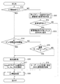
以下、本実施形態に係る電子スチルカメラによる、ライブビュー動作開始釦207を押下したときと、オートフォーカスのピント調整値(以下、AFピント調整値と称する)の変更指示があったときの処理について説明する。図3は、マイクロコンピュータ39が実行する処理の流れを示すフローチャートである。
Hereinafter, processing when the electronic still camera according to the present embodiment presses the live view
まずステップS10で、マイクロコンピュータ39は、ライブビュー動作開始釦207が押下されているか否かの判定を行い、押下されているならばステップS14に移行し、押下されていないならばステップS11に移行する。
First, in step S10, the
ステップS11で、マイクロコンピュータ39は、ライブビューを使用するAFピント調整値の変更が可能か否か、すなわちライブビューを伴ったAFピント調整値の変更が可能な変更モードに移行可能が否かの判定を行う。ステップS11についての詳細は後述する。ステップS12で、マイクロコンピュータ39は、ライブビューを使用するAFピント調整値の変更指示があるか否かの判定を行い、変更指示があるならばステップS13に移行し、変更指示が無いならば本処理を終了する。ステップS13で、マイクロコンピュータ39は、ライブビューを使用するAFピント調整値の変更指示があったことの情報を不揮発性メモリ38に格納し、その後ステップS14に移行する。
In step S11, the
ステップS14で、マイクロコンピュータ39は、ステップS13において格納した情報に基づいて、AFピント調整値の変更を開始するか否かの判定を行い、開始するならばステップS16に移行し、開始しないのであればステップS15に移行する。
In step S14, the
ステップS15で、マイクロコンピュータ39は、現在の撮影モードがマニュアルモードであるか否かの判定を行い、マニュアルモードであればステップS18に移行し、マニュアルモードでなければステップS16に移行する。
In step S15, the
ステップS16で、マイクロコンピュータ39は、AEセンサ15より被写体の輝度を取得する。ステップS17で、マイクロコンピュータ39は、ステップS16において取得された被写体の輝度に対応してプログラム線図に沿ったTv値(電子シャッタ速度)、Av値(絞り値)、ISO値(撮影感度)を設定する。
In step S <b> 16, the
ここで、被写体の輝度から露出量を決定するプログラム線図について、図4を参照して説明する。図4は、ユーザが設定した設定値によらずに、適切な露出量となるようなTv値、Av値、ISO値を取得するためのプログラム線図である。ライブビュー画像を表示するフレームレートは30fpsとしている。このため、Tv値が1/30秒以上の低速秒時の場合は、ISO値を上げることで適切な露出量が得られるようにする。このプログラム線図が選択された場合、ユーザが任意に設定している設定値は用いずに、被写体の輝度とプログラム線図からTv値、Av値、ISO値が設定される。例えばユーザが設定していたAv値がAV5.6、被写体の輝度がEV5であった場合、Tv値は1/30(秒)、Av値は2.0、ISO値は400とすることで、適切な露出量の画像を得ることができる。
Here, a program diagram for determining the exposure amount from the luminance of the subject will be described with reference to FIG. FIG. 4 is a program diagram for obtaining a Tv value, an Av value, and an ISO value that can provide an appropriate exposure amount regardless of the setting value set by the user. The frame rate for displaying the live view image is 30 fps. For this reason, when the Tv value is a low-speed time of 1/30 seconds or more, an appropriate exposure amount can be obtained by increasing the ISO value. When this program diagram is selected, the Tv value, Av value, and ISO value are set from the luminance of the subject and the program diagram without using the setting value that is arbitrarily set by the user. For example, when the Av value set by the user is AV 5.6 and the luminance of the subject is
一方、ステップS18で、マイクロコンピュータ39は、ユーザが設定したTv値、Av値、ISO値を不揮発性メモリ38から読み込む。
On the other hand, in step S <b> 18, the
そして、ステップS19で、マイクロコンピュータ39は、ステップS17、S18において取得されたTv値、Av値、ISO値に基づいてライブビューの開始処理を行う。
In step S19, the
以上のように、ライブビューを使用するAFピント調整値の変更指示があった場合、被写体の輝度から露出量を決定するプログラム線図に基づいてTv値、Av値、ISO値を決定してライブビューを実行させる。また、ライブビューの開始操作があり、ライブビューを使用するAFピント調整値の変更指示がなかった場合で、マニュアルモードでないときにも、被写体の輝度から露出量を決定するプログラム線図に基づいてTv値、Av値、ISO値を決定してライブビューを実行させる。それに対して、ライブビューの開始操作があり、ライブビューを使用するAFピント調整値の変更指示がなかった場合で、マニュアルモードであるときは、ユーザが設定したTv値、Av値、ISO値を用いてライブビューを実行させる。 As described above, when there is an instruction to change the AF focus adjustment value using the live view, the Tv value, the Av value, and the ISO value are determined based on the program diagram for determining the exposure amount from the luminance of the subject. Run the view. Also, when there is a live view start operation and there is no instruction to change the AF focus adjustment value that uses live view, even when not in manual mode, based on the program diagram that determines the exposure amount from the brightness of the subject The Tv value, Av value, and ISO value are determined and live view is executed. On the other hand, when there is a live view start operation and there is no instruction to change the AF focus adjustment value using the live view, and in the manual mode, the Tv value, Av value, and ISO value set by the user are set. Use to run live view.
次に、図5を参照して、ステップS19のライブビューの開始処理について詳細に説明する。ステップS100では、クイックリターンミラー12をアップさせる。ステップS101では、ステップS17又はステップS18において設定されたAv値をマイクロコンピュータ39より通信端子6、10を介してレンズシステム制御回路4に送信し、絞り駆動回路2を介して絞り1を絞り込ませる。ステップS102では、フォーカルプレーンシャッタ17を開く。ステップS103では、ステップS17又はステップS18において設定されたTvに基づいて、タイミング制御回路32を介して撮像素子20の駆動タイミングを制御する。また、アンプ回路21を介してステップS17又はステップS18において設定されたISO値に応じたゲインで撮影信号を増幅し、A/D変換回路22を介してデジタル信号に変換し、画像処理回路23を介して画像データをバッファメモリ26に取り込む。
Next, the live view start process in step S19 will be described in detail with reference to FIG. In step S100, the
ステップS104では、ステップS13において格納した情報に基づいて、AFピント調整値の変更指示がなければステップS105に進み、あればステップS106に進む。ステップS105では、バッファメモリ26に取り込まれた画像データをメモリコントローラ27を介してアナログ信号に変換して、液晶駆動回路24を介して液晶表示部25に出力する。このときは、図6(a)に示すように、通常のライブビュー表示となる。それに対して、ステップS106では、バッファメモリ26に取り込まれた画像データを画像処理回路23を介して拡大処理し、メモリコントローラ27を介してアナログ信号に変換して、液晶駆動回路24を介して液晶表示部25に出力する。このときは、図6(b)に示すように、拡大されたライブビュー表示となる。
In step S104, if there is no instruction to change the AF focus adjustment value based on the information stored in step S13, the process proceeds to step S105, and if there is, the process proceeds to step S106. In step S <b> 105, the image data captured in the
次に、図7を参照して、ステップS11のライブビューを使用するAFピント調整値の変更が可能か否かの判定処理について詳細に説明する。ステップS200で、通信端子10を介して、現在装着されているレンズユニット100の情報を取得する。ここで取得する情報は、少なくとも、そのレンズ固有のIDナンバー、名称、開放絞り値であるとする。
Next, with reference to FIG. 7, a detailed description will be given of a process for determining whether or not the AF focus adjustment value using the live view in step S <b> 11 can be changed. In step S <b> 200, information on the
ステップS201では、ステップS200において取得したレンズのIDナンバー又は名称からAF可能なレンズか否かの判定を行う。その結果、AF可能なレンズであればステップS202に進み、AF不可能なレンズであればステップS204に進む。 In step S201, it is determined whether the lens is AF-capable from the lens ID number or name acquired in step S200. As a result, if the lens is AF-capable, the process proceeds to step S202. If the lens is not AF-capable, the process proceeds to step S204.
ステップS202では、ステップS200において取得したレンズの開放絞り値が所定の閾値よりも明るいか否かの判定を行う。その結果、所定の基準よりも明るければ(すなわち、所定の閾値よりも小さければ)ステップS203に進み、所定の基準よりも暗ければ(すなわち、所定の閾値よりも大きければ)ステップS204に進む。 In step S202, it is determined whether or not the open aperture value of the lens acquired in step S200 is brighter than a predetermined threshold value. As a result, if it is brighter than the predetermined reference (that is, smaller than the predetermined threshold), the process proceeds to step S203, and if it is darker than the predetermined reference (that is, larger than the predetermined threshold), the process proceeds to step S204.
ステップS203では、ライブビューを使用するAFピント調整値の変更が可能であるとして、図8(a)に示すように、ライブビューを使用するAFピント調整値の変更を行うか、ライブビューを使用しないAFピント調整値の変更を行うかの選択を促すGUI画面を表示する。図8(a)には、ライブビューを使用するAFピント調整値の選択部が選択された状態を示す。図3のステップS12で、ユーザがライブビューを使用するAFピント調整値の選択部を選択することで、ライブビューを使用するAFピント調整値の変更指示が出される。 In step S203, assuming that the AF focus adjustment value using the live view can be changed, as shown in FIG. 8A, the AF focus adjustment value using the live view is changed or the live view is used. A GUI screen that prompts the user to select whether to change the AF focus adjustment value is displayed. FIG. 8A shows a state where the AF focus adjustment value selection unit using the live view is selected. In step S12 of FIG. 3, the user selects an AF focus adjustment value selection unit that uses a live view, whereby an instruction to change the AF focus adjustment value that uses the live view is issued.
それに対して、ステップS204では、AFピント調整値の変更が不可能であるとして、図8(b)に示すように、AFピント調整値の選択部をグレーアウトするようなGUI画面を表示する。 On the other hand, in step S204, assuming that the AF focus adjustment value cannot be changed, a GUI screen for graying out the AF focus adjustment value selection unit is displayed as shown in FIG. 8B.
以上のように制御することで、AFピント調整値の変更を行う際のライブビュー表示は、ユーザの設定によらず、常に適したものとなって、且つ拡大画像を表示することが可能となる。これにより、AFピント調整値の変更を行う際に、自らの設定値を設定し直すこともなく、またピント確認のために、拡大操作をユーザ自身がする手間も無くなり、簡易に視覚的に分かりやすく、AFピントの調整を行うことができるようになる。 By controlling as described above, the live view display when changing the AF focus adjustment value is always suitable regardless of the user setting, and an enlarged image can be displayed. . As a result, when the AF focus adjustment value is changed, it is not necessary to reset the set value of the user himself / herself, and there is no need for the user himself to perform the enlargement operation for the focus confirmation. This makes it easy to adjust the AF focus.
また、オートフォーカス機能が無いか若しくは、不可能なレンズ群に対して、ライブビューを使用するAFピント調整の変更を防止することを可能にし、不要な調整値が入ることを防ぎ、また、ライブビューによる電力の消費低減も図ることが可能となる。 In addition, it is possible to prevent changes in AF focus adjustment using live view for lens groups that have no or impossible autofocus function, and prevent unwanted adjustment values from being entered. It is also possible to reduce power consumption by the view.
以上、本発明の好ましい実施形態について説明したが、本発明はこれらの実施形態に限定されず、その要旨の範囲内で種々の変形及び変更が可能である。
(その他の実施形態)
また、本発明は、以下の処理を実行することによっても実現される。すなわち、上述した実施形態の機能を実現するソフトウェア(プログラム)を、ネットワーク又は各種記憶媒体を介してシステム或いは装置に供給し、そのシステム或いは装置のコンピュータ(又はCPUやMPU等)がプログラムを読み出して実行する処理である。
As mentioned above, although preferable embodiment of this invention was described, this invention is not limited to these embodiment, A various deformation | transformation and change are possible within the range of the summary.
(Other embodiments)
The present invention can also be realized by executing the following processing. That is, software (program) that realizes the functions of the above-described embodiments is supplied to a system or apparatus via a network or various storage media, and a computer (or CPU, MPU, etc.) of the system or apparatus reads the program. It is a process to be executed.
1:絞り、2:絞り駆動回路、3:AF駆動回路、4:レンズシステム制御回路、5:レンズ、6:レンズ側通信部、10:カメラ側通信部、11:AFセンサ、12:クイックリターンミラー、13:フォーカシングスクリーン、14:ペンタプリズム、15:AEセンサ、16:ファインダ、17:フォーカルプレーンシャッタ、18:光学フィルタ、19:圧電素子、20:撮像素子、21:アンプ回路、22:A/D変換回路、23:画像処理回路、24:液晶駆動回路、25:液晶表示部、26:バッファメモリ、27:メモリコントローラ、28:外部メモリ、29:外部インタフェース、30:AC電源部、31:2次電池部、32:タイミング制御回路、33:電源種類検知回路、34:電源状態検知回路、35:電源制御回路、36:シャッタ制御回路、37:光学フィルタ振動制御回路。38:不揮発性メモリ、39:マイクロコンピュータ、100:レンズユニット、200:カメラ本体、201:レリーズ釦、202:モードダイヤル、203:電子ダイヤル、204:十字キー及び選択釦、205:電源スイッチ、206:スイッチ群、207:ライブビュー動作開始釦 1: aperture, 2: aperture drive circuit, 3: AF drive circuit, 4: lens system control circuit, 5: lens, 6: lens side communication unit, 10: camera side communication unit, 11: AF sensor, 12: quick return Mirror, 13: Focusing screen, 14: Penta prism, 15: AE sensor, 16: Finder, 17: Focal plane shutter, 18: Optical filter, 19: Piezoelectric element, 20: Image sensor, 21: Amplifier circuit, 22: A / D conversion circuit, 23: image processing circuit, 24: liquid crystal drive circuit, 25: liquid crystal display unit, 26: buffer memory, 27: memory controller, 28: external memory, 29: external interface, 30: AC power supply unit, 31 : Secondary battery unit, 32: timing control circuit, 33: power supply type detection circuit, 34: power supply state detection circuit, 35: power supply control Road, 36: shutter control circuit, 37: optical filter vibration control circuit. 38: nonvolatile memory, 39: microcomputer, 100: lens unit, 200: camera body, 201: release button, 202: mode dial, 203: electronic dial, 204: cross key and selection button, 205: power switch, 206 : Switch group, 207: Live view operation start button
Claims (7)
表示部に被写体像を表示するライブビューを行う表示制御手段と、
被写体の輝度を測光する測光手段と、
ユーザが設定した電子シャッタ速度、絞り値、ISO値を保存する保存手段と、
ライブビュー開始の前に、前記変更モードへの移行指示の有無を判定し、
前記変更モードへの移行指示がなければ、ユーザによって選択された撮影モードに応じて定められる電子シャッタ速度、絞り値、ISO値に従ってライブビューを実行させ、
前記変更モードへの移行指示があれば、前記保存手段に保存した電子シャッタ速度、絞り値、ISO値を用いずに、前記測光手段で測光した被写体の輝度に対応して電子シャッタ速度、絞り値、ISO値を決定するプログラム線図でライブビューを実行させる制御手段とを備えたことを特徴とする撮像装置。 An image pickup apparatus having a change mode capable of changing a focus adjustment value of autofocus accompanied by a live view,
Display control means for performing live view for displaying a subject image on the display unit;
A metering means for metering the brightness of the subject;
Storage means for storing the electronic shutter speed, aperture value, and ISO value set by the user;
Before starting live view, determine whether there is an instruction to transition to the change mode,
If there is no instruction to shift to the change mode, the live view is executed according to the electronic shutter speed, aperture value, and ISO value determined according to the shooting mode selected by the user ,
If there is an instruction to shift to the change mode, the electronic shutter speed and aperture value corresponding to the brightness of the subject measured by the photometry means are used without using the electronic shutter speed, aperture value, and ISO value stored in the storage means. An imaging apparatus comprising: control means for executing a live view with a program diagram for determining an ISO value .
被写体の輝度を測光する測光手段と、ユーザが設定した電子シャッタ速度、絞り値、ISO値を保存する保存手段とを用いて、
ライブビュー開始の前に、前記変更モードへの移行指示の有無を判定し、
前記変更モードへの移行指示がなければ、ユーザによって選択された撮影モードに応じて定められる電子シャッタ速度、絞り値、ISO値に従ってライブビューを実行させ、
前記変更モードへの移行指示があれば、前記保存手段に保存した電子シャッタ速度、絞り値、ISO値を用いずに、前記測光手段で測光した被写体の輝度に対応して電子シャッタ速度、絞り値、ISO値を決定するプログラム線図でライブビューを実行させる手順を有することを特徴とする撮像装置の制御方法。 A control method of an imaging apparatus having a change mode capable of changing a focus adjustment value of autofocus accompanied by a live view that displays a subject image on a display unit,
Using photometric means for measuring the brightness of the subject and storage means for storing the electronic shutter speed, aperture value, and ISO value set by the user,
Before starting live view, determine whether there is an instruction to transition to the change mode,
If there is no instruction to shift to the change mode, the live view is executed according to the electronic shutter speed, aperture value, and ISO value determined according to the shooting mode selected by the user ,
If there is an instruction to shift to the change mode, the electronic shutter speed and aperture value corresponding to the brightness of the subject measured by the photometry means are used without using the electronic shutter speed, aperture value, and ISO value stored in the storage means. A method for controlling an imaging apparatus, comprising a step of executing a live view with a program diagram for determining an ISO value .
被写体の輝度を測光する測光手段と、ユーザが設定した電子シャッタ速度、絞り値、ISO値を保存する保存手段とを用いて、
ライブビュー開始の前に、前記変更モードへの移行指示の有無を判定し、
前記変更モードへの移行指示がなければ、ユーザによって選択された撮影モードに応じて定められる電子シャッタ速度、絞り値、ISO値に従ってライブビューを実行させ、
前記変更モードへの移行指示があれば、前記保存手段に保存した電子シャッタ速度、絞り値、ISO値を用いずに、前記測光手段で測光した被写体の輝度に対応して電子シャッタ速度、絞り値、ISO値を決定するプログラム線図でライブビューを実行させる処理をコンピュータに実行させるためのプログラム。 A program for controlling an image pickup apparatus having a change mode capable of changing an autofocus focus adjustment value with a live view for displaying a subject image on a display unit,
Using photometric means for measuring the brightness of the subject and storage means for storing the electronic shutter speed, aperture value, and ISO value set by the user,
Before starting live view, determine whether there is an instruction to transition to the change mode,
If there is no instruction to shift to the change mode, the live view is executed according to the electronic shutter speed, aperture value, and ISO value determined according to the shooting mode selected by the user ,
If there is an instruction to shift to the change mode, the electronic shutter speed and aperture value corresponding to the brightness of the subject measured by the photometry means are used without using the electronic shutter speed, aperture value, and ISO value stored in the storage means. A program for causing a computer to execute a process for executing a live view with a program diagram for determining an ISO value .
Priority Applications (3)
| Application Number | Priority Date | Filing Date | Title |
|---|---|---|---|
| JP2011082165A JP5967865B2 (en) | 2011-04-01 | 2011-04-01 | IMAGING DEVICE, IMAGING DEVICE CONTROL METHOD, AND PROGRAM |
| US13/419,736 US8896742B2 (en) | 2011-04-01 | 2012-03-14 | Image pickup apparatus, and control method and program thereof |
| CN201210093331.5A CN102739939B (en) | 2011-04-01 | 2012-03-31 | Image pickup apparatus, and control method thereof |
Applications Claiming Priority (1)
| Application Number | Priority Date | Filing Date | Title |
|---|---|---|---|
| JP2011082165A JP5967865B2 (en) | 2011-04-01 | 2011-04-01 | IMAGING DEVICE, IMAGING DEVICE CONTROL METHOD, AND PROGRAM |
Publications (3)
| Publication Number | Publication Date |
|---|---|
| JP2012217100A JP2012217100A (en) | 2012-11-08 |
| JP2012217100A5 JP2012217100A5 (en) | 2015-04-30 |
| JP5967865B2 true JP5967865B2 (en) | 2016-08-10 |
Family
ID=46926777
Family Applications (1)
| Application Number | Title | Priority Date | Filing Date |
|---|---|---|---|
| JP2011082165A Expired - Fee Related JP5967865B2 (en) | 2011-04-01 | 2011-04-01 | IMAGING DEVICE, IMAGING DEVICE CONTROL METHOD, AND PROGRAM |
Country Status (3)
| Country | Link |
|---|---|
| US (1) | US8896742B2 (en) |
| JP (1) | JP5967865B2 (en) |
| CN (1) | CN102739939B (en) |
Families Citing this family (9)
| Publication number | Priority date | Publication date | Assignee | Title |
|---|---|---|---|---|
| KR20140089672A (en) * | 2013-01-04 | 2014-07-16 | 삼성전자주식회사 | Digital photographing apparatus, method for controlling the same, and computer-readable recording medium |
| JP6028928B2 (en) * | 2013-04-16 | 2016-11-24 | オリンパス株式会社 | Imaging apparatus and imaging method |
| JP5704476B1 (en) * | 2014-06-24 | 2015-04-22 | 株式会社ビジョナリスト | Digital photo analysis apparatus and digital photo analysis program |
| CN107431764B (en) | 2015-03-27 | 2018-08-21 | 富士胶片株式会社 | The control method of camera, camera main body and camera |
| JP6548501B2 (en) * | 2015-07-31 | 2019-07-24 | キヤノン株式会社 | Imaging device, control method therefor, program, and storage medium |
| JP6745682B2 (en) * | 2016-08-30 | 2020-08-26 | キヤノン株式会社 | Imaging device, control method, program, and storage medium |
| CN108521864B (en) * | 2017-10-20 | 2021-01-05 | 深圳市大疆创新科技有限公司 | Imaging control method, imaging device and unmanned aerial vehicle |
| JP7062455B2 (en) | 2018-02-07 | 2022-05-06 | キヤノン株式会社 | Electronic devices and their control methods |
| CN112153296B (en) * | 2019-06-27 | 2022-04-05 | 杭州海康威视数字技术股份有限公司 | Automatic exposure control method and device and camera with FPGA |
Family Cites Families (21)
| Publication number | Priority date | Publication date | Assignee | Title |
|---|---|---|---|---|
| CN1003972B (en) | 1985-12-31 | 1989-04-19 | 长春邮电学院 | Auto-focusing method used in optical lens of television camera |
| SE461619B (en) * | 1988-07-06 | 1990-03-05 | Hasselblad Ab Victor | DEVICE FOR CAMERAS CONCERNING A COMPOSITION OF A PHOTOCHEMICAL AND ELECTRONIC CAMERA |
| JP3978996B2 (en) * | 2000-10-30 | 2007-09-19 | カシオ計算機株式会社 | Imaging apparatus and imaging processing method |
| JP2003289472A (en) * | 2002-03-28 | 2003-10-10 | Nikon Gijutsu Kobo:Kk | Electronic camera |
| JP4378141B2 (en) * | 2003-09-29 | 2009-12-02 | キヤノン株式会社 | Image pickup apparatus and image pickup apparatus control method |
| JP2006003533A (en) * | 2004-06-16 | 2006-01-05 | Canon Inc | Imaging apparatus, focusing control method and program |
| JP4173457B2 (en) * | 2004-03-12 | 2008-10-29 | 富士フイルム株式会社 | Imaging apparatus and control method thereof |
| JP4489608B2 (en) * | 2004-03-31 | 2010-06-23 | 富士フイルム株式会社 | DIGITAL STILL CAMERA, IMAGE REPRODUCTION DEVICE, FACE IMAGE DISPLAY DEVICE, AND CONTROL METHOD THEREOF |
| US7590290B2 (en) * | 2004-07-21 | 2009-09-15 | Canon Kabushiki Kaisha | Fail safe image processing apparatus |
| JP2006208782A (en) * | 2005-01-28 | 2006-08-10 | Canon Inc | Camera |
| JP4240023B2 (en) * | 2005-08-31 | 2009-03-18 | ソニー株式会社 | Imaging apparatus, imaging method and imaging program, and image processing apparatus, image processing method and image processing program |
| JP4804210B2 (en) * | 2006-04-18 | 2011-11-02 | キヤノン株式会社 | Imaging apparatus and control method thereof |
| JP4854581B2 (en) * | 2007-04-24 | 2012-01-18 | キヤノン株式会社 | Imaging apparatus and control method thereof |
| JP2008276115A (en) * | 2007-05-07 | 2008-11-13 | Olympus Imaging Corp | Digital camera and focus control program |
| JP2010068046A (en) * | 2008-09-08 | 2010-03-25 | Olympus Imaging Corp | Imaging apparatus |
| JP5132497B2 (en) * | 2008-09-16 | 2013-01-30 | キヤノン株式会社 | IMAGING DEVICE AND IMAGING DEVICE CONTROL METHOD |
| JP5230376B2 (en) | 2008-11-28 | 2013-07-10 | 三星電子株式会社 | Imaging apparatus and imaging method |
| CN101778214B (en) | 2009-01-09 | 2011-08-31 | 华晶科技股份有限公司 | Digital image pick-up device having brightness and focusing compensation function and image compensation method thereof |
| JP2010262173A (en) * | 2009-05-08 | 2010-11-18 | Sony Corp | Imaging apparatus and photographic lens unit |
| JP5517514B2 (en) * | 2009-07-16 | 2014-06-11 | キヤノン株式会社 | Imaging apparatus and control method thereof |
| CN103460104B (en) * | 2011-03-25 | 2016-08-10 | 佳能株式会社 | Camera head |
-
2011
- 2011-04-01 JP JP2011082165A patent/JP5967865B2/en not_active Expired - Fee Related
-
2012
- 2012-03-14 US US13/419,736 patent/US8896742B2/en not_active Expired - Fee Related
- 2012-03-31 CN CN201210093331.5A patent/CN102739939B/en not_active Expired - Fee Related
Also Published As
| Publication number | Publication date |
|---|---|
| CN102739939A (en) | 2012-10-17 |
| CN102739939B (en) | 2015-07-01 |
| US20120249848A1 (en) | 2012-10-04 |
| JP2012217100A (en) | 2012-11-08 |
| US8896742B2 (en) | 2014-11-25 |
Similar Documents
| Publication | Publication Date | Title |
|---|---|---|
| JP5967865B2 (en) | IMAGING DEVICE, IMAGING DEVICE CONTROL METHOD, AND PROGRAM | |
| US8988579B2 (en) | Imaging apparatus | |
| JP4614143B2 (en) | Imaging apparatus and program thereof | |
| JP5709629B2 (en) | Imaging apparatus and control method | |
| JP2008078738A (en) | Imaging apparatus and its control method | |
| JP5629456B2 (en) | Imaging apparatus and control method thereof | |
| JP2012029055A (en) | Imaging device, control method of the same, program, and storage medium | |
| JP5493273B2 (en) | Imaging apparatus, imaging method, and program | |
| JP2010190913A (en) | Imaging device with automatic focus function | |
| JP2009086036A (en) | Imaging device and control method for imaging device | |
| JP2017009815A (en) | Focus detection device, focus detection method, and camera system | |
| JP5353866B2 (en) | Imaging apparatus and program | |
| JP2015055775A (en) | Imaging device and imaging device control method | |
| JP2006173860A (en) | Electronic camera | |
| JP2003029137A (en) | Automatic focusing detector | |
| JP4848763B2 (en) | Imaging apparatus and program | |
| JP4369350B2 (en) | Imaging device | |
| JP2007033997A (en) | Focal point detecting apparatus | |
| JP2005221578A (en) | Imaging apparatus, control method thereof, program and storage medium | |
| JP2016092798A (en) | Imaging apparatus and control method of the same | |
| JP2011087107A (en) | Imaging apparatus, method for controlling the same and program | |
| JP2018085669A (en) | Imaging apparatus and control method of the same | |
| JP2014126796A (en) | Imaging device, control method for imaging device and program | |
| JP5003339B2 (en) | Camera system | |
| JP2012247736A (en) | Imaging apparatus and control method for imaging apparatus |
Legal Events
| Date | Code | Title | Description |
|---|---|---|---|
| A621 | Written request for application examination |
Free format text: JAPANESE INTERMEDIATE CODE: A621 Effective date: 20140327 |
|
| A977 | Report on retrieval |
Free format text: JAPANESE INTERMEDIATE CODE: A971007 Effective date: 20150113 |
|
| A521 | Request for written amendment filed |
Free format text: JAPANESE INTERMEDIATE CODE: A523 Effective date: 20150317 |
|
| A131 | Notification of reasons for refusal |
Free format text: JAPANESE INTERMEDIATE CODE: A131 Effective date: 20150929 |
|
| A521 | Request for written amendment filed |
Free format text: JAPANESE INTERMEDIATE CODE: A523 Effective date: 20151127 |
|
| TRDD | Decision of grant or rejection written | ||
| A01 | Written decision to grant a patent or to grant a registration (utility model) |
Free format text: JAPANESE INTERMEDIATE CODE: A01 Effective date: 20160607 |
|
| A61 | First payment of annual fees (during grant procedure) |
Free format text: JAPANESE INTERMEDIATE CODE: A61 Effective date: 20160705 |
|
| R151 | Written notification of patent or utility model registration |
Ref document number: 5967865 Country of ref document: JP Free format text: JAPANESE INTERMEDIATE CODE: R151 |
|
| LAPS | Cancellation because of no payment of annual fees |