JP5966325B2 - Measuring apparatus, measuring method and parameter setting method - Google Patents
Measuring apparatus, measuring method and parameter setting method Download PDFInfo
- Publication number
- JP5966325B2 JP5966325B2 JP2011247571A JP2011247571A JP5966325B2 JP 5966325 B2 JP5966325 B2 JP 5966325B2 JP 2011247571 A JP2011247571 A JP 2011247571A JP 2011247571 A JP2011247571 A JP 2011247571A JP 5966325 B2 JP5966325 B2 JP 5966325B2
- Authority
- JP
- Japan
- Prior art keywords
- light
- receiving element
- light emitting
- light receiving
- amount
- Prior art date
- Legal status (The legal status is an assumption and is not a legal conclusion. Google has not performed a legal analysis and makes no representation as to the accuracy of the status listed.)
- Expired - Fee Related
Links
- 238000000034 method Methods 0.000 title description 21
- 238000005259 measurement Methods 0.000 claims description 174
- 230000003287 optical effect Effects 0.000 claims description 55
- 238000000926 separation method Methods 0.000 claims description 23
- 239000000126 substance Substances 0.000 claims description 18
- 230000005855 radiation Effects 0.000 claims description 5
- 238000009434 installation Methods 0.000 claims description 3
- 238000003384 imaging method Methods 0.000 claims 1
- 210000003491 skin Anatomy 0.000 description 41
- 102000001554 Hemoglobins Human genes 0.000 description 18
- 108010054147 Hemoglobins Proteins 0.000 description 18
- CNQCVBJFEGMYDW-UHFFFAOYSA-N lawrencium atom Chemical compound [Lr] CNQCVBJFEGMYDW-UHFFFAOYSA-N 0.000 description 14
- 238000004364 calculation method Methods 0.000 description 11
- 102000017011 Glycated Hemoglobin A Human genes 0.000 description 8
- XUMBMVFBXHLACL-UHFFFAOYSA-N Melanin Chemical compound O=C1C(=O)C(C2=CNC3=C(C(C(=O)C4=C32)=O)C)=C2C4=CNC2=C1C XUMBMVFBXHLACL-UHFFFAOYSA-N 0.000 description 8
- 108091005995 glycated hemoglobin Proteins 0.000 description 7
- 230000003595 spectral effect Effects 0.000 description 7
- 230000008033 biological extinction Effects 0.000 description 6
- 238000013461 design Methods 0.000 description 6
- 238000012545 processing Methods 0.000 description 6
- 238000002835 absorbance Methods 0.000 description 5
- 230000008859 change Effects 0.000 description 5
- 230000007423 decrease Effects 0.000 description 5
- 238000000691 measurement method Methods 0.000 description 5
- 108010064719 Oxyhemoglobins Proteins 0.000 description 4
- 239000008280 blood Substances 0.000 description 4
- 210000004369 blood Anatomy 0.000 description 4
- 150000002772 monosaccharides Chemical class 0.000 description 4
- 239000000758 substrate Substances 0.000 description 4
- QVGXLLKOCUKJST-UHFFFAOYSA-N atomic oxygen Chemical compound [O] QVGXLLKOCUKJST-UHFFFAOYSA-N 0.000 description 3
- 210000004207 dermis Anatomy 0.000 description 3
- 229910052760 oxygen Inorganic materials 0.000 description 3
- 239000001301 oxygen Substances 0.000 description 3
- 238000001228 spectrum Methods 0.000 description 3
- BPYKTIZUTYGOLE-IFADSCNNSA-N Bilirubin Chemical compound N1C(=O)C(C)=C(C=C)\C1=C\C1=C(C)C(CCC(O)=O)=C(CC2=C(C(C)=C(\C=C/3C(=C(C=C)C(=O)N\3)C)N2)CCC(O)=O)N1 BPYKTIZUTYGOLE-IFADSCNNSA-N 0.000 description 2
- CURLTUGMZLYLDI-UHFFFAOYSA-N Carbon dioxide Chemical compound O=C=O CURLTUGMZLYLDI-UHFFFAOYSA-N 0.000 description 2
- 230000004308 accommodation Effects 0.000 description 2
- 238000010586 diagram Methods 0.000 description 2
- 230000000694 effects Effects 0.000 description 2
- 210000002615 epidermis Anatomy 0.000 description 2
- 210000004185 liver Anatomy 0.000 description 2
- 238000002834 transmittance Methods 0.000 description 2
- 229910052724 xenon Inorganic materials 0.000 description 2
- FHNFHKCVQCLJFQ-UHFFFAOYSA-N xenon atom Chemical compound [Xe] FHNFHKCVQCLJFQ-UHFFFAOYSA-N 0.000 description 2
- 102000008186 Collagen Human genes 0.000 description 1
- 108010035532 Collagen Proteins 0.000 description 1
- WQZGKKKJIJFFOK-GASJEMHNSA-N Glucose Natural products OC[C@H]1OC(O)[C@H](O)[C@@H](O)[C@@H]1O WQZGKKKJIJFFOK-GASJEMHNSA-N 0.000 description 1
- 108010014663 Glycated Hemoglobin A Proteins 0.000 description 1
- 102000011782 Keratins Human genes 0.000 description 1
- 108010076876 Keratins Proteins 0.000 description 1
- 230000002159 abnormal effect Effects 0.000 description 1
- 238000010521 absorption reaction Methods 0.000 description 1
- 230000001154 acute effect Effects 0.000 description 1
- 229910002092 carbon dioxide Inorganic materials 0.000 description 1
- 239000001569 carbon dioxide Substances 0.000 description 1
- 229920001436 collagen Polymers 0.000 description 1
- 150000001875 compounds Chemical class 0.000 description 1
- -1 glucose Chemical class 0.000 description 1
- 239000008103 glucose Substances 0.000 description 1
- 230000036541 health Effects 0.000 description 1
- 230000001678 irradiating effect Effects 0.000 description 1
- 210000004072 lung Anatomy 0.000 description 1
- 239000000463 material Substances 0.000 description 1
- 230000037353 metabolic pathway Effects 0.000 description 1
- 230000004060 metabolic process Effects 0.000 description 1
- 238000012986 modification Methods 0.000 description 1
- 230000004048 modification Effects 0.000 description 1
- 238000012544 monitoring process Methods 0.000 description 1
- 239000005416 organic matter Substances 0.000 description 1
- 206010033675 panniculitis Diseases 0.000 description 1
- 230000008569 process Effects 0.000 description 1
- 102000004169 proteins and genes Human genes 0.000 description 1
- 108090000623 proteins and genes Proteins 0.000 description 1
- 230000009467 reduction Effects 0.000 description 1
- 238000002310 reflectometry Methods 0.000 description 1
- 238000010187 selection method Methods 0.000 description 1
- 238000005549 size reduction Methods 0.000 description 1
- 210000004304 subcutaneous tissue Anatomy 0.000 description 1
- 239000013076 target substance Substances 0.000 description 1
- 230000007704 transition Effects 0.000 description 1
Images


Classifications
-
- A—HUMAN NECESSITIES
- A61—MEDICAL OR VETERINARY SCIENCE; HYGIENE
- A61B—DIAGNOSIS; SURGERY; IDENTIFICATION
- A61B5/00—Measuring for diagnostic purposes; Identification of persons
- A61B5/0059—Measuring for diagnostic purposes; Identification of persons using light, e.g. diagnosis by transillumination, diascopy, fluorescence
- A61B5/0075—Measuring for diagnostic purposes; Identification of persons using light, e.g. diagnosis by transillumination, diascopy, fluorescence by spectroscopy, i.e. measuring spectra, e.g. Raman spectroscopy, infrared absorption spectroscopy
-
- A—HUMAN NECESSITIES
- A61—MEDICAL OR VETERINARY SCIENCE; HYGIENE
- A61B—DIAGNOSIS; SURGERY; IDENTIFICATION
- A61B5/00—Measuring for diagnostic purposes; Identification of persons
- A61B5/0059—Measuring for diagnostic purposes; Identification of persons using light, e.g. diagnosis by transillumination, diascopy, fluorescence
- A61B5/0077—Devices for viewing the surface of the body, e.g. camera, magnifying lens
- A61B5/0079—Devices for viewing the surface of the body, e.g. camera, magnifying lens using mirrors, i.e. for self-examination
-
- G—PHYSICS
- G01—MEASURING; TESTING
- G01N—INVESTIGATING OR ANALYSING MATERIALS BY DETERMINING THEIR CHEMICAL OR PHYSICAL PROPERTIES
- G01N21/00—Investigating or analysing materials by the use of optical means, i.e. using sub-millimetre waves, infrared, visible or ultraviolet light
- G01N21/17—Systems in which incident light is modified in accordance with the properties of the material investigated
- G01N21/47—Scattering, i.e. diffuse reflection
- G01N21/4738—Diffuse reflection, e.g. also for testing fluids, fibrous materials
- G01N21/474—Details of optical heads therefor, e.g. using optical fibres
- G01N2021/4752—Geometry
- G01N2021/4761—Mirror arrangements, e.g. in IR range
Landscapes
- Health & Medical Sciences (AREA)
- Life Sciences & Earth Sciences (AREA)
- Physics & Mathematics (AREA)
- General Health & Medical Sciences (AREA)
- Pathology (AREA)
- Engineering & Computer Science (AREA)
- Animal Behavior & Ethology (AREA)
- Veterinary Medicine (AREA)
- Public Health (AREA)
- Surgery (AREA)
- Molecular Biology (AREA)
- Biophysics (AREA)
- Medical Informatics (AREA)
- Biomedical Technology (AREA)
- Heart & Thoracic Surgery (AREA)
- Chemical & Material Sciences (AREA)
- Analytical Chemistry (AREA)
- Biochemistry (AREA)
- Immunology (AREA)
- General Physics & Mathematics (AREA)
- Spectroscopy & Molecular Physics (AREA)
- Investigating Or Analysing Materials By Optical Means (AREA)
- Measurement Of The Respiration, Hearing Ability, Form, And Blood Characteristics Of Living Organisms (AREA)
- Measuring And Recording Apparatus For Diagnosis (AREA)
Description
本開示は、測定装置、測定方法及びパラメータの設定方法に関する。 The present disclosure relates to a measurement apparatus, a measurement method, and a parameter setting method.
測定対象物に対して光を照射し、測定対象物からの反射光を測定することで、測定対象物を分析する分光測定方法が、従来より提案されている。かかる分光測定方法では、測定対象物からの反射光を漏らさず集光するために、積分球と呼ばれる光学装置が用いられることが多い。このような積分球を用いた分光測定方法では、大きく分けて以下の2種類のような測定手順が存在する。 Conventionally, a spectroscopic measurement method for analyzing a measurement object by irradiating the measurement object with light and measuring reflected light from the measurement object has been proposed. In such a spectroscopic measurement method, an optical device called an integrating sphere is often used to collect the reflected light from the measurement object without leaking. In such a spectroscopic measurement method using an integrating sphere, there are roughly the following two types of measurement procedures.
(1)発光素子からの照射光を測定対象物に対して多角的に集光し、反射光を分光フィルタ前でコリメートして導光して、測定対象物の分光反射率を測定する。
(2)被測定対象物からの拡散反射を分光フィルタへ多角的に集光し、反射光を分光フィルタ前でコリメートして導光して、測定対象物の分光反射率を測定する。
(1) Irradiation light from the light emitting element is collected from various angles with respect to the measurement object, and the reflected light is collimated and guided in front of the spectral filter to measure the spectral reflectance of the measurement object.
(2) The diffuse reflection from the object to be measured is condensed in a multifaceted manner on the spectral filter, the reflected light is collimated and guided in front of the spectral filter, and the spectral reflectance of the measurement object is measured.
また、照射光としてキセノンランプ等の白色光源を用い、測定対象物からの反射光を分光フィルタで数十波長に分光することが一般的に行われる。 In general, a white light source such as a xenon lamp is used as the irradiation light, and the reflected light from the measurement object is spectrally divided into several tens of wavelengths with a spectral filter.
また、例えば以下の特許文献1に記載されているように、積分球を用いずに、測定対象物からの光を測定する分光測定装置も提案されている。 For example, as described in Patent Document 1 below, a spectroscopic measurement apparatus that measures light from a measurement object without using an integrating sphere has also been proposed.
しかしながら、上述のような積分球を用いた分光測定装置は、積分球や反射光をコリメートするための光学素子を用いる必要があるため装置の小型化が困難であるという問題があった。また、照射光源として利用されるキセノン光源は、発光を得るために光源装置に対して高い電力を供給する必要があり、省電力化が困難であるとともに、数十波長分もの分光フィルタを設けるために、低コスト化が困難である。 However, the spectroscopic measurement apparatus using the integrating sphere as described above has a problem that it is difficult to reduce the size of the apparatus because it is necessary to use an integrating sphere or an optical element for collimating reflected light. In addition, a xenon light source used as an irradiation light source needs to supply high power to the light source device to obtain light emission, and it is difficult to save power, and a spectral filter for several tens of wavelengths is provided. In addition, cost reduction is difficult.
また、上記特許文献1に記載の方法においても、回折格子を用いて測定対象物からの光を分光しているため、装置全体としての小型化を図ることが困難であった。 Also in the method described in Patent Document 1, since the light from the measurement object is dispersed using the diffraction grating, it is difficult to reduce the size of the entire apparatus.
そこで、本開示では、上記事情に鑑みて、装置の更なる小型化を図ることが可能な、測定装置、測定方法及びパラメータの設定方法を提供する。 Therefore, in view of the above circumstances, the present disclosure provides a measuring device, a measuring method, and a parameter setting method that can further reduce the size of the device.
本開示によれば、測定対象物の載置された測定対象領域と対向する位置に設けられ、当該測定対象領域からの光が結像する受光素子と、前記受光素子の周囲に配設され、前記測定対象物を測定するための光を射出する複数の発光素子と、前記発光素子の上方に設けられ、当該発光素子から射出された放射発光を、前記測定対象領域へと導光する反射光学素子と、を備え、前記受光素子の受光面と、前記複数の発光素子の光射出面とは、互いに同一の平面上に位置しており、前記複数の発光素子から射出された前記放射発光は前記反射光学素子により反射され、それぞれの前記発光素子からの前記放射発光の中心線が前記測定対象領域の略中心を通過する測定装置が提供される。 According to the present disclosure, a light receiving element provided at a position facing a measurement target area on which a measurement target is placed, a light receiving element that forms an image of light from the measurement target area, and disposed around the light receiving element, A plurality of light emitting elements that emit light for measuring the measurement object, and reflective optics that is provided above the light emitting elements and guides radiated light emitted from the light emitting elements to the measurement target region A light receiving surface of the light receiving element and a light emitting surface of the plurality of light emitting elements are located on the same plane, and the emitted light emitted from the plurality of light emitting elements is There is provided a measuring apparatus that is reflected by the reflective optical element and in which the center line of the emitted light from each of the light emitting elements passes through the approximate center of the measurement target region.
また、本開示によれば、測定対象物の載置された測定対象領域と対向する位置に設けられ、当該測定対象領域からの光が結像する受光素子の周囲に配設され、前記測定対象物を測定するための光を射出する複数の発光素子から、前記測定対象物を測定するための光を射出させることと、前記複数の発光素子から射出されたそれぞれの放射発光を、当該放射発光の中心線が前記測定対象領域の略中心を通過するように、前記発光素子の上方に設けられた反射光学素子により前記測定対象領域へと導光することと、前記測定対象領域からの反射光を前記受光素子で受光することと、を含み、前記受光素子の受光面と、前記複数の発光素子の光射出面とは、互いに同一の平面上に位置している測定方法が提供される。 Further, according to the present disclosure, the measurement target is provided at a position facing the measurement target region on which the measurement target is placed, and is disposed around a light receiving element on which light from the measurement target region is imaged. Emitting light for measuring the object to be measured from a plurality of light emitting elements that emit light for measuring an object, and radiating light emitted from each of the plurality of light emitting elements Is guided to the measurement target area by a reflective optical element provided above the light emitting element so that the center line of the measurement light passes through the approximate center of the measurement target area, and the reflected light from the measurement target area And a light receiving surface of the light receiving element and a light emitting surface of the plurality of light emitting elements are provided on the same plane.
また、本開示によれば、測定対象物の載置された測定対象領域と対向する位置に設けられ、当該測定対象領域からの光が結像する受光素子と、前記受光素子の周囲に配設され、前記測定対象物を測定するための光を射出する複数の発光素子と、前記発光素子の上方に設けられ、当該発光素子から射出された放射発光を、前記測定対象領域へと導光する反射光学素子と、を備え、前記受光素子の受光面と、前記複数の発光素子の光射出面とは、互いに同一の平面上に位置しており、前記複数の発光素子から射出された前記光は前記反射光学素子により反射され、それぞれの前記発光素子からの前記放射発光の中心線が前記測定対象領域の略中心を通過する測定装置において、前記受光素子が受光する前記測定対象物からの反射光の光量の最低値を設定し、設定した前記反射光の光量の最低値に基づいて前記受光素子の大きさを決定することと、前記測定対象領域の大きさを、前記受光素子に求められる信号雑音比と設定した前記反射光の光量の最低値とに基づいて設定するとともに、前記受光素子と前記測定対象物との間の離隔距離を、前記受光素子への入射光量と前記反射光の光量の最低値とに基づいて設定することと、を含む、パラメータの設定方法が提供される。 Further, according to the present disclosure, the light receiving element that is provided at a position facing the measurement target region on which the measurement target is placed and that forms an image of light from the measurement target region is disposed around the light receiving element. A plurality of light emitting elements that emit light for measuring the measurement object, and radiated light emitted from the light emitting elements and guided from the light emitting elements to the measurement target region. A light receiving surface of the light receiving element and a light emitting surface of the plurality of light emitting elements are located on the same plane, and the light emitted from the plurality of light emitting elements. Is reflected by the reflective optical element and reflected from the measurement object received by the light receiving element in a measuring apparatus in which the center line of the emitted light from each light emitting element passes through the approximate center of the measurement target region. Minimum light intensity Setting, determining the size of the light receiving element based on the set minimum value of the amount of reflected light, and setting the size of the measurement target region to the signal-to-noise ratio required for the light receiving element And setting the separation distance between the light receiving element and the measurement object based on the incident light quantity to the light receiving element and the minimum light quantity of the reflected light. Parameter setting method is provided.
本開示によれば、受光素子の受光面と同一の平面上に、受光素子の周囲に位置する複数の発光素子から放射発光が射出され、射出された放射発光は、発光素子の上方に位置する反射光学素子により反射されて測定対象領域に載置された測定対象物に照射され、測定対象物からの拡散反射光は、受光素子に結像する。 According to the present disclosure, radiated light is emitted from a plurality of light emitting elements located around the light receiving element on the same plane as the light receiving surface of the light receiving element, and the emitted radiated light is located above the light emitting element. The measurement object reflected by the reflective optical element and irradiated on the measurement object region is irradiated, and diffused reflected light from the measurement object forms an image on the light receiving element.
以上説明したように本開示によれば、装置の更なる小型化を図ることが可能である。 As described above, according to the present disclosure, it is possible to further reduce the size of the apparatus.
以下に添付図面を参照しながら、本開示の好適な実施の形態について詳細に説明する。なお、本明細書及び図面において、実質的に同一の機能構成を有する構成要素については、同一の符号を付することにより重複説明を省略する。 Hereinafter, preferred embodiments of the present disclosure will be described in detail with reference to the accompanying drawings. In addition, in this specification and drawing, about the component which has the substantially same function structure, duplication description is abbreviate | omitted by attaching | subjecting the same code | symbol.
なお、説明は、以下の順序で行うものとする。
(1)第1の実施形態
(1−1)測定装置の全体構成について
(1−2)光学系の構成について
(1−3)パラメータの設定方法について
(2)測定装置の適用例について
The description will be made in the following order.
(1) First Embodiment (1-1) About Overall Configuration of Measuring Device (1-2) About Configuration of Optical System (1-3) About Parameter Setting Method (2) Application Example of Measuring Device
(第1の実施形態)
<測定装置の全体構成について>
まず、図1A及び図1Bを参照しながら、本開示の第1の実施形態に係る測定装置の全体構成について、簡単に説明する。図1A及び図1Bは、本実施形態に係る測定装置の全体構成を模式的に示した説明図である。
(First embodiment)
<Overall configuration of measuring device>
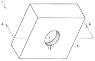
First, the overall configuration of the measurement apparatus according to the first embodiment of the present disclosure will be briefly described with reference to FIGS. 1A and 1B. 1A and 1B are explanatory views schematically showing the overall configuration of the measuring apparatus according to the present embodiment.
本実施形態に係る測定装置1は、図1Aに示したように、任意の材質からなる筺体11を有しており、筺体11の一部には、開口部13が設けられている。図1Aにおいて、開口部13の形状は円形状であるが、開口部13の形状は円形状に限定されるわけではなく、多角形形状であっても、楕円形状であってもよい。この開口部13の部分に測定対象物が載置され、本実施形態に係る測定装置1は、載置された測定対象物に対して、測定を実施する。
As shown in FIG. 1A, the measuring apparatus 1 according to the present embodiment includes a
ここで、開口部13に載置される測定対象物は、ミー散乱効果等により当該測定対象物からの反射光が極めて散乱・拡散しやすい、有機物であることが好ましい。このような有機物として、例えば、有機ELディスプレイにおける有機発光層等の有機物を含有している物体や、人体の皮膚面や各種の細胞等を挙げることができる。
Here, the measurement object placed in the
図1Bは、図1AをA−A切断線で切断した断面を示した断面図である。
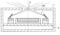
図1Bに示したように、筺体11の内部は中空となっており、筺体11の内部には、本実施形態に係る測定装置1の光学系100が実装されている。また、筺体11の内壁は、光学系100からの漏れ光の反射を抑制するために、黒、又は、黒に準ずる暗い色調の色とすることが好ましい。
FIG. 1B is a cross-sectional view showing a cross section of FIG. 1A taken along the line AA.
As shown in FIG. 1B, the inside of the
ここで、筺体11の内部に実装されている光学系100については、以下で改めて詳細に説明する。また、図1Bでは、筺体11の内部に光学系100のみが存在するように図示されているが、筺体11の内部には、光学系100での測定処理に影響を与えない範囲で、光学系100以外にも任意のユニットが実装されていてもよい。
Here, the
<光学系の構成について>
続いて、図2A〜図2Cを参照しながら、本実施形態に係る測定装置1が備える光学系について、詳細に説明する。
<Configuration of optical system>
Next, the optical system provided in the measurement apparatus 1 according to the present embodiment will be described in detail with reference to FIGS. 2A to 2C.
図2Aは、本実施形態に係る光学系100を、開口部13の側から見た場合の平面図であり、図2Bは、本実施形態に係る光学系100を、図2Aの中心線で切断した場合の断面図である。また、図2Cは、本実施形態に係る光学系100の発光素子103の近傍を拡大して示した説明図である。なお、以下では、開口部13に人体の皮膚面が載置され、開口部13に載置された皮膚面が測定対象領域となっている場合について説明する。
FIG. 2A is a plan view of the
図2A及び図2Bに示したように、本実施形態に係る光学系100は、基板等の任意の形状を有する収容ユニットBに配置された受光素子101と、基板等の任意の形状を有する収容ユニットBに配置された複数の発光素子103と、ミラー等の反射光学素子105と、を有している。
As shown in FIGS. 2A and 2B, the
受光素子101には、測定対象物の載置された測定対象領域からの散乱反射光が結像される。受光素子101は、受光面に結像した光の光量等に応じて、結像した光の光量を表すデータ等を生成する。このような受光素子101として、例えばフォトダイオードを挙げることができるが、本実施形態に係る受光素子101は、上記のものに限定されるわけではなく、他の光センサを利用することも可能である。
Scattered and reflected light from the measurement target region on which the measurement target is placed is imaged on the
この受光素子101は、図2A及び図2Bに示したように、測定装置1の筺体11に設けられた開口部13と対向するように配設されており、開口部13の中心が、受光素子101の中心と対向している。
2A and 2B, the
また、本実施形態に係る測定装置1では、測定対象物(例えば、人体の皮膚面)からの反射光を可能な限り漏らさず受光するために、図2Aに示したように、受光素子101は、開口部13の面積よりも十分に大きな受光面積を有するようにする。更に、本実施形態に係る測定装置1では、測定対象物からの反射光を可能な限り漏らさず受光するために、受光素子101と開口部13との間の離隔距離dを、十分に小さくする。これにより、本実施形態に係る測定装置1では、測定装置1の厚みを低減することができ、測定装置の小型化を図ることが可能となる。
Moreover, in the measuring apparatus 1 according to the present embodiment, in order to receive the reflected light from the measurement object (for example, the skin surface of the human body) as much as possible, the
ここで、受光素子101が、測定対象物からの反射光をどのくらい受光するかについては、測定装置1に求められる精度等に応じて適宜設定すればよいが、ガウス校正板等の白色校正板(白色拡散反射板)からの反射光の光量を基準として、例えば95%以上とすることが好ましい。
Here, how much the
なお、受光素子101が受光する測定対象物からの反射光量は、大きければ大きい程好ましいが、測定対象物からの反射光を100%受光するためには、積分球を用いなければならず、光学系の設計寸法、ひいては測定装置の大きさが大型化してしまう可能性がある。しかしながら、本実施形態に係る測定装置1では、以下で詳述するように、受光素子101に受光させる反射光の光量と、受光素子における信号雑音比(SNR)を保証するために求められる受光素子への入射光量と、のトレードオフ関係が成立する範囲で、受光素子の大きさ、開口部の大きさ、及び、受光素子と開口部との間の離隔距離の3つのパラメータを設定し、測定装置の小型化を図っている。
The larger the amount of reflected light from the measurement object received by the
また、図2A及び図2Bに示したように、受光素子101の周囲には、複数の発光素子103a〜103h(以下、まとめて発光素子103ともいう。)が、受光素子101の4つの辺に沿って配設されている。これら受光素子101の光射出面は、図2Bに示したように、受光素子101の受光面と互いに同一の平面上に存在している。ここで、複数の発光素子103の光射出面と受光素子101の受光面とは、互いに同一の平面上に存在していればよく、受光素子101及び複数の発光素子103は、同一の基板上に配設されていてもよいし、異なる基板上に配設されていてもよい。
2A and 2B, around the
このような発光素子103として、例えば、発光ダイオード(LED)を利用することが可能である。また、本実施形態に係る発光素子103として、所定の波長の放射光を射出する発光素子を利用してもよいし、白色光を放射する発光素子と、所望の波長の光を得るためのフィルタと、を組み合わせて利用してもよい。
As such a
本実施形態に係る測定装置1では、上記のようなN個(図2Aでは8個)の発光素子103が、受光素子101の周囲に配置され、M(M≦N)種類の波長の光を射出する。また、発光素子101から射出される放射光の波長は、測定対象物の種別や測定対象とする物質等に応じて適宜選択すればよい。
In the measuring apparatus 1 according to the present embodiment, the N (eight in FIG. 2A)
ここで、(波長数M<発光素子の個数N)である場合には、ある波長の光を射出する光を複数個配置することが可能となる。この際、本実施形態に係る測定装置1では、許容される波長幅が狭く、発光素子自身又はフィルタ等を介した光量が小さい光から優先して、複数の発光素子103を配置することが好ましい。
Here, when (the number of wavelengths M <the number N of light emitting elements), it is possible to arrange a plurality of lights that emit light of a certain wavelength. At this time, in the measuring apparatus 1 according to the present embodiment, it is preferable to arrange the plurality of
以下、M<Nである場合における波長の選択方法に関し、人体の皮膚面を例にとって具体的に説明する。 Hereinafter, the wavelength selection method in the case of M <N will be specifically described by taking a human skin surface as an example.
図3は、可視光波長帯域(400nm〜700nm)における人間の皮膚の反射率を測定した測定結果である。図3から明らかなように、人間の皮膚は、400nm〜500nm近傍の帯域では反射率がなだらかに増加し、その後600nm近傍の帯域までは反射率がわずかに減少し、600nm近傍から650nm近傍までは反射率が急激に増加する。 FIG. 3 shows measurement results obtained by measuring the reflectance of human skin in the visible light wavelength band (400 nm to 700 nm). As is clear from FIG. 3, the human skin has a moderate increase in the reflectance in the band near 400 nm to 500 nm, and then the reflectance slightly decreases to the band near 600 nm, and from around 600 nm to around 650 nm. The reflectivity increases rapidly.
ここで、人間の皮膚を測定対象とする場合に、図3に示したような可視光波長帯域の全てに着目したのでは、可視光波長帯域全ての光を放射可能な光源が必要となり、また、各波長の光量を特定するために、回折格子等の分光素子が必要となってしまう。その結果、測定装置の小型化を図ることが困難となってしまうことが予想される。 Here, in the case where human skin is a measurement target, if attention is paid to all visible light wavelength bands as shown in FIG. 3, a light source capable of emitting light in all visible light wavelength bands is required. In order to specify the light quantity of each wavelength, a spectroscopic element such as a diffraction grating is required. As a result, it is expected that it will be difficult to reduce the size of the measuring apparatus.
そこで、本実施形態に係る測定装置1では、測定対象とする現象や物質に特徴的な波長をM種類選択することで、特殊な光源や分光素子を用いなくとも、測定対象とする現象や物質を効率良く測定することを実現する。例えば、図3に示した人間の皮膚の場合、スペクトルに特徴的な波長位置は、図4に示した5点である。そこで、本実施形態に係る測定装置1では、図4に示した5種類の波長に着目することで、人間の皮膚を効率良く測定する。なお、かかる5種類の波長は、人間の血中に存在する酸化ヘモグロビン、糖化ヘモグロビン、還元ヘモグロビン等の各種のヘモグロビンを測定対象とする場合にも有用な波長である。 Therefore, in the measuring apparatus 1 according to the present embodiment, by selecting M types of wavelengths characteristic of the phenomenon or substance to be measured, the phenomenon or substance to be measured without using a special light source or spectroscopic element. Can be measured efficiently. For example, in the case of the human skin shown in FIG. 3, the wavelength positions characteristic of the spectrum are the five points shown in FIG. Therefore, in the measuring apparatus 1 according to the present embodiment, the human skin is efficiently measured by paying attention to the five types of wavelengths shown in FIG. These five types of wavelengths are also useful when measuring various types of hemoglobin such as oxyhemoglobin, glycated hemoglobin, and reduced hemoglobin present in human blood.
また、図3に示したスペクトルの形状に着目すると、波長580nmの近傍では、反射率が急激に立ち上がるため、波長580nmの光に着目する場合には、この波長の光に許容される波長幅が狭いことがわかる。逆に、例えば波長540nmの近傍では、反射率はなだらかに推移しているため、波長540nmの光に着目する場合には、この波長の光に許容される波長幅を比較的大きく設定してもよいことがわかる。このような観点から、図4に示した5つの波長の波長幅を考慮すると、例えば以下のように設定することができる。
Further, when focusing on the shape of the spectrum shown in FIG. 3, the reflectance rises rapidly in the vicinity of the wavelength of 580 nm. Therefore, when focusing on the light of
λ1(青):500±25nm
λ2(緑):540±15nm
λ3(黄):580± 5nm
λ4(赤):620±15nm
λ5(赤):660±15nm
λ 1 (blue): 500 ± 25 nm
λ 2 (green): 540 ± 15 nm
λ 3 (yellow): 580 ± 5 nm
λ 4 (red): 620 ± 15 nm
λ 5 (red): 660 ± 15 nm
ここで、図2Aに示した光学系100に対して上記5種類の波長を射出する発光素子103を実装する場合、着目する波長の光量や許容される波長幅に応じて、例えば、λ1及びλ2の波長の光を射出可能な発光素子を1個ずつ配設し、λ3、λ4、λ5の波長の光を射出可能な発光素子を2個ずつ配設することができる。ここで、同一の波長の光を射出可能な発光素子103を複数実装する場合、同一の波長の光を射出可能な発光素子は、受光素子101の中心を基準として点対称の位置となるように配設することが好ましい。
Here, when the light-emitting
それぞれの発光素子103から射出された放射光は、発光素子103上に設けられたレンズ等の集光素子やアパーチャ等(図示せず。)により所定の開口数NAの光とされ、ミラー等の反射光学素子105へと進むこととなる。ここで、上記開口数NAの値は、0.2とすることが好ましい。開口数NAが0.2よりも大きくなると、測定対象領域に照射されなくなる放射光の割合が増加していくため、好ましくない。
The radiated light emitted from each light emitting
ミラー等の反射光学素子105は、図2A〜図2Cに示したように、発光素子103の上方に設けられており、発光素子103から射出された放射発光を、当該放射発光の中心線が測定対象領域の略中心を通過するように、測定対象領域へと導光する。この反射光学素子105は、各発光素子103の直上に個別に設けられていてもよいし、例えば図2Aに示したように、複数の発光素子103に共通の反射光学素子105が設けられていてもよい。
As shown in FIGS. 2A to 2C, the reflective
また、発光素子103の光射出面と反射光学素子105の反射面とのなす角(図2Cにおける角度α)の大きさは、受光素子101と開口部13との間の離隔距離dや、放射発光の開口数NA等に応じて決定される。
In addition, the size of the angle (angle α in FIG. 2C) formed by the light emitting surface of the
本実施形態に係る測定装置1では、発光素子103の上方に反射光学素子105を設けることで、図2Bに示した離隔距離dが小さな場合であっても、発光素子103からの放射発光を測定対象領域(換言すれば、開口部13)の略中心へと照射することが可能となり、測定装置1の小型化(薄型化)に寄与することができる。
In the measurement apparatus 1 according to the present embodiment, by providing the reflective
以上、図1A〜図4を参照しながら、本実施形態に係る測定装置1の全体構成について、詳細に説明した。 The overall configuration of the measuring apparatus 1 according to the present embodiment has been described in detail above with reference to FIGS. 1A to 4.
本実施形態に係る測定装置1では、上記のような構成を有することにより、測定対象物の載置された測定対象領域に対して、受光素子101の周囲に設けられた複数の発光素子103から、測定対象物を測定するための放射発光が射出され、それぞれの放射発光は、放射発光の中心線が測定対象領域の略中心を通過するように、発光素子の上方に設けられた反射光学素子105により測定対象領域へと導光され、測定対象物のミー散乱効果等により散乱・拡散した反射光が、受光素子101に結像することとなる。
In the measuring apparatus 1 according to the present embodiment, by having the above-described configuration, from the plurality of
<パラメータの設定方法について>
以下では、図5〜図7を参照しながら、本実施形態に係る測定装置1における設計パラメータの設定方法について詳細に説明するとともに、各パラメータの設定例について、具体的に説明する。図5は、受光素子に入射する測定対象領域からの反射光量の分布を模式的に示したグラフ図である。図6は、測定対象領域からの反射光量と受光素子の信号雑音比との関係を模式的に示したグラフ図である。図7は、測定対象領域からの反射光量と受光素子への入射光量との関係を模式的に示したグラフ図である。
<Parameter setting method>
Hereinafter, a design parameter setting method in the measurement apparatus 1 according to the present embodiment will be described in detail with reference to FIGS. 5 to 7, and an example of setting each parameter will be specifically described. FIG. 5 is a graph schematically showing the distribution of the amount of reflected light from the measurement target region incident on the light receiving element. FIG. 6 is a graph schematically showing the relationship between the amount of reflected light from the measurement target region and the signal-to-noise ratio of the light receiving element. FIG. 7 is a graph schematically showing the relationship between the amount of light reflected from the measurement target region and the amount of light incident on the light receiving element.
本実施形態に係る測定装置1を設計する際の主なパラメータとしては、例えば、受光素子101の大きさ、開口部の大きさ、受光素子101と開口部13との間の離隔距離等を挙げることができる。所望の測定精度を実現しつつ、測定装置1の小型化を図るためには、これらの設計パラメータをいかに設定するかが重要となる。
As main parameters when designing the measuring apparatus 1 according to the present embodiment, for example, the size of the
本実施形態に係る測定装置1は、測定対象物からの反射光に基づいて、所望の物質の測定を行うものであるため、反射光をどのくらい受光することが可能であるか、が重要なファクターとなる。そこで、本実施形態に係る測定装置1におけるパラメータの設定方法では、まず、受光素子101が受光することが可能な反射光の光量(換言すれば、受光素子101が受光可能な反射光の光量の最低値)を設定することが行われる。 Since the measuring apparatus 1 according to the present embodiment measures a desired substance based on reflected light from a measurement object, an important factor is how much the reflected light can be received. It becomes. Therefore, in the parameter setting method in the measurement apparatus 1 according to this embodiment, first, the amount of reflected light that can be received by the light receiving element 101 (in other words, the amount of reflected light that can be received by the light receiving element 101). The lowest value is set.
その後、本実施形態に係るパラメータの設定方法では、設定された反射光の光量に基づいて、受光素子101の大きさ、測定対象領域(開口部13)の大きさ、及び、受光素子101と開口部13との間の離隔距離のそれぞれが、互いに独立して設定される。
Thereafter, in the parameter setting method according to the present embodiment, the size of the
[受光素子の大きさの設定方法]
まず、図5を参照しながら、受光素子の大きさの設定方法について説明する。
図5は、受光素子に入射する測定対象物からの反射光の光量分布を示したグラフ図である。グラフ図の横軸は、受光素子の断面方向の長さ(例えば図2Bにおける長さA)を表しており、グラフ図の縦軸は、受光素子へ入射する反射光の光量を表している。
[How to set the size of the light receiving element]
First, a method for setting the size of the light receiving element will be described with reference to FIG.
FIG. 5 is a graph showing the light amount distribution of the reflected light from the measurement object incident on the light receiving element. The horizontal axis of the graph represents the length of the light receiving element in the cross-sectional direction (for example, length A in FIG. 2B), and the vertical axis of the graph represents the amount of reflected light incident on the light receiving element.
図5に示したグラフ図には、白色校正板の一例であるガウス校正板からの拡散反射光量の分布が記載されている。ガウス校正板からの拡散反射光の分布は、図5に示したように、ほぼガウス分布となっている。また、図5に示したグラフ図には、皮膚からの散乱反射光の分布もあわせて記載されている。図5から明らかなように、皮膚からの散乱反射光の分布は、ミー散乱等のために、ガウス校正板からの散乱反射光の分布よりも広がることがわかる。そのため、受光素子の大きさ(断面方向長さ)が小さい場合には、受光素子101は十分な光量の散乱反射光を受光することが出来ず、測定精度が低下することとなる。
The graph shown in FIG. 5 describes the distribution of diffuse reflection light from a Gaussian calibration plate, which is an example of a white calibration plate. As shown in FIG. 5, the distribution of diffusely reflected light from the Gaussian calibration plate is almost Gaussian. The graph shown in FIG. 5 also shows the distribution of scattered reflected light from the skin. As is apparent from FIG. 5, the distribution of scattered reflected light from the skin is broader than the distribution of scattered reflected light from the Gaussian calibration plate due to Mie scattering and the like. Therefore, when the size of the light receiving element (the length in the cross-sectional direction) is small, the
本実施形態に係るパラメータの設定方法では、受光素子101が受光することが可能な反射光の光量の最低値を、ガウス校正板からの拡散反射光量を基準とした割合で表すこととする。ガウス校正板からの拡散反射光量は、図5に示したガウス校正板からの拡散反射光量の分布曲線と、グラフの横軸とで囲まれる領域の面積として表される。従って、受光素子101が受光可能な反射光の光量の設定値が決定されると、皮膚からの拡散反射光量の分布曲線の面積に着目することで、光量の設定値を実現するための分布曲線の裾野の広さを決定することができる。
In the parameter setting method according to the present embodiment, the minimum value of the amount of reflected light that can be received by the
例えば、受光素子101により、ガウス校正板からの拡散反射光量の95%を受光するようにしたい場合には、原点を中心としてガウス校正板からの拡散反射光量の95%となる面積を与える、皮膚からの散乱反射光量の分布曲線の範囲を決定する。このようにして規定される範囲の大きさを、受光素子101の大きさ(断面方向長さ)と設定することができる。このような方法により、95%という受光光量を実現可能な受光素子101の断面方向長さを、10mmと設定することができた。従って、本実施形態に係る測定装置1では、受光素子101として、10mm×10mmの受光素子を利用可能であることが明らかとなった。
For example, when it is desired to receive 95% of the diffuse reflected light amount from the Gaussian calibration plate by the
[開口部の大きさの設定方法]
続いて、図6を参照しながら、開口部の大きさの設定方法について説明する。
図6は、開口部の大きさ(具体的には、図2Bに示した円形の開口部の直径a)を変化させた場合における皮膚からの反射光量の変化の様子と、受光素子101への入射光量の変化の様子をそれぞれ示したグラフ図である。グラフ図の横軸は、開口部13の直径を表しており、グラフ図の縦軸は、皮膚からの反射光量の割合と、受光素子101へ入射しうる光量(μW)とをそれぞれ表している。
[How to set the opening size]
Next, a method for setting the size of the opening will be described with reference to FIG.
FIG. 6 shows how the amount of reflected light from the skin changes when the size of the opening (specifically, the diameter a of the circular opening shown in FIG. 2B) is changed, It is the graph which each showed the mode of the change of incident light quantity. The horizontal axis of the graph represents the diameter of the
図6において細線で示したグラフ図は、受光素子101へ入射しうる皮膚からの反射光の光量の変化を示したものである。開口部13の大きさが大きくなるにつれて開口部13に載置される皮膚の面積も大きくなるため、図6に示したように、皮膚から受光素子101へ向かって散乱する反射光の光量も増加することとなり、受光素子101へ入射しうる光量は増加することとなる。
The graph shown by the thin line in FIG. 6 shows the change in the amount of reflected light from the skin that can enter the
図6において太線で示したグラフ図は、ある一定の大きさを有する受光素子(図6では、10mm×10mmの受光素子)が受光する皮膚からの反射光量の割合の変化を示したものである。開口部13の大きさが大きくなるにつれて皮膚からの反射光量も大きくなるものの、開口部13の大きさがある閾値を超えると、受光素子101の大きさが一定である場合には、受光できない反射光が増加するため、受光素子101が受光する皮膚からの反射光量の割合は、急激に減少していくこととなる。
6 is a graph showing a change in the ratio of the amount of light reflected from the skin received by a light receiving element having a certain size (light receiving element of 10 mm × 10 mm in FIG. 6). . Although the amount of reflected light from the skin increases as the size of the opening
このように、ある一定の大きさを有する受光素子101が受光する反射光量と、受光素子へ入射しうる反射光量とは、互いにトレードオフの関係となっていることがわかる。
Thus, it can be seen that the amount of reflected light received by the
受光素子101により検出される信号の信号雑音比(SNR)を維持するためには、ある程度の光量が受光素子101に入射することが求められる。所定の信号雑音比を維持するための入射光量の閾値が10μWである場合、図6に示したように、開口部13の大きさは、4.6mm以上とすることが好ましい。逆に、95%以上の反射光量を受光素子101が受光するためには、図6に示したように、開口部13の大きさは、5.4mm以下とすることが好ましい。従って、開口部13の大きさを、4.6mm〜5.4mm(5.0mm±0.4mm)と設定することで、検出される信号の信号雑音比を維持しつつ、皮膚からの反射光量の95%以上を検知することが可能となる。
In order to maintain the signal-to-noise ratio (SNR) of the signal detected by the
[受光素子と開口部との離隔距離の設定方法]
続いて、図7を参照しながら、受光素子101と開口部13との離隔距離の設定方法について説明する。
図7は、ある一定の大きさを有する開口部、及び、ある一定の大きさを有する受光素子を考え、開口部(換言すれば、測定対象物である皮膚)と受光素子との間の離隔距離(図2Bにおける距離d)を変化させた場合に着目し、皮膚からの反射光量の変化の様子と、受光素子101への入射光量の変化の様子をそれぞれ示したグラフ図である。グラフ図の横軸は、受光素子と開口部との離隔距離を表しており、グラフ図の縦軸は、皮膚からの反射光量の割合と、受光素子101へ入射しうる光量(μW)とをそれぞれ表している。
[Method of setting the separation distance between the light receiving element and the opening]
Next, a method for setting a separation distance between the
FIG. 7 considers an opening having a certain size and a light receiving element having a certain size, and the separation between the opening (in other words, the skin that is the measurement object) and the light receiving device. FIG. 4 is a graph showing changes in the amount of reflected light from the skin and changes in the amount of incident light on the
図7において細線で示したグラフ図は、受光素子101へ入射しうる皮膚からの反射光の光量の変化を示したものである。離隔距離dが大きくなるにつれて、受光素子101が受光する光量も増加していくが、離隔距離dがある閾値を超えると、開口部13と受光素子101との間の隙間から反射光が受光素子101へと入射しなくなり、入射光量は減少していくこととなる。
The graph shown by the thin line in FIG. 7 shows the change in the amount of reflected light from the skin that can enter the
図7において太線で示したグラフ図は、ある一定の大きさを有する受光素子(図7では、10mm×10mmの受光素子)が受光する皮膚からの反射光量の割合の変化を示したものである。離隔距離dがある閾値を超えると、受光素子101の大きさが一定である場合には、受光できない反射光が増加する。そのため、図7に示したように、受光素子101が受光する皮膚からの反射光量の割合は、急激に減少していくこととなる。
7 is a graph showing a change in the ratio of the amount of reflected light from the skin received by a light receiving element having a certain size (in FIG. 7, a light receiving element of 10 mm × 10 mm). . When the separation distance d exceeds a certain threshold value, the reflected light that cannot be received increases if the size of the
このように、ある一定の大きさを有する受光素子101が受光する反射光量と、受光素子へ入射しうる反射光量とは、互いにトレードオフの関係となっていることがわかる。
Thus, it can be seen that the amount of reflected light received by the
受光素子101により検出される信号の信号雑音比(SNR)を維持するためには、ある程度の光量が受光素子101に入射することが求められる。所定の信号雑音比を維持するための入射光量の閾値が10μWである場合、図7に示したように、離隔距離dは、2.8mm以上とすることが好ましい。逆に、95%以上の反射光量を受光素子101が受光するためには、図7に示したように、開口部13の大きさは、3.2mm以下とすることが好ましい。従って、離隔距離dの大きさを、2.8mm〜3.2mm(3.0mm±0.2mm)と設定することで、検出される信号の信号雑音比を維持しつつ、皮膚からの反射光量の95%以上を検知することが可能となる。
In order to maintain the signal-to-noise ratio (SNR) of the signal detected by the
以上のような設計指針に基づき、設定される各パラメータの値をまとめると、以下のようになる。
○皮膚からの反射光量の最低値を95%と設定した場合
受光素子101の大きさ:10mm×10mm
開口部13の大きさ(直径):5mm±0.4mmφ
受光素子101と開口部13との離隔距離:3mm±0.2mm
Based on the design guidelines as described above, the values of the set parameters are summarized as follows.
○ When the minimum value of the amount of reflected light from the skin is set to 95% Size of the light receiving element 101: 10 mm × 10 mm
Size (diameter) of the opening 13: 5 mm ± 0.4 mmφ
Separation distance between the
また、上記のようなパラメータを有する測定装置1において、開口数NA=0.2の放射光を開口部13へと導光するためには、図2Cにおける反射光学素子105の設置角度αを51°とすればよいことが明らかとなった。
Further, in the measuring apparatus 1 having the parameters as described above, in order to guide the radiated light having the numerical aperture NA = 0.2 to the
このような設計指針に基づいてパラメータを設定することで、本実施形態に係る測定装置1では、発光素子からの放射発光が受光素子と開口部との間のわずかな隙間から鋭角で測定対象物へと照射されるにもかかわらず、受光素子で反射光を精度よく検出することが可能となる。 By setting parameters based on such design guidelines, in the measuring apparatus 1 according to this embodiment, the radiated light from the light emitting element is measured at an acute angle from a slight gap between the light receiving element and the opening. In spite of being irradiated, the reflected light can be accurately detected by the light receiving element.
以上、図5〜図7を参照しながら、本実施形態に係る測定装置1における設計パラメータの設定方法について詳細に説明するとともに、各パラメータの設定例について、具体的に説明した。 The design parameter setting method in the measuring apparatus 1 according to the present embodiment has been described in detail with reference to FIGS. 5 to 7, and the setting examples of each parameter have been specifically described.
<測定装置の適用例について>
続いて、図8及び図9を参照しながら、本開示の実施形態に係る測定装置の適用例について、簡単に説明する。図8及び図9は、本開示の実施形態に係る測定装置の適用例を説明するための説明図である。
<Application example of measuring device>
Subsequently, an application example of the measurement apparatus according to the embodiment of the present disclosure will be briefly described with reference to FIGS. 8 and 9. 8 and 9 are explanatory diagrams for describing an application example of the measurement apparatus according to the embodiment of the present disclosure.
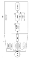
本開示の実施形態に係る測定装置1は、例えば図8に示したように、演算処理装置200と組み合わせて使用することで、例えば、人間の皮膚の特定の波長での反射率を測定し、測定結果を評価する装置に適用することが可能である。
For example, as shown in FIG. 8, the measurement device 1 according to the embodiment of the present disclosure is used in combination with the
例えば図8に示した例では、本開示の実施形態に係る測定装置1は、N種類の波長を有する光を人間の皮膚に照射して、人間の皮膚での反射光を受光素子101で受光する。その結果、受光素子101は、受光した反射光に関する測定情報を生成する。測定装置1は、受光素子101により生成された測定情報を、演算処理装置200に対して出力する。
For example, in the example illustrated in FIG. 8, the measurement apparatus 1 according to the embodiment of the present disclosure irradiates the human skin with light having N types of wavelengths, and the
演算処理装置200の測定情報取得部201は、測定装置1により生成された測定情報(例えば、任意の肌反射スペクトルや特定の波長での反射率等の情報)を測定装置1から取得して、演算部203に出力する。
The measurement
演算部203は、測定情報取得部201が取得した測定情報に基づいて、例えばランベルト・ベールの法則等に則して演算を行って、人間の皮膚の内部に存在する、各種の物質の存在量等を算出する。
Based on the measurement information acquired by the measurement
人間の皮膚は、体表面に近い場所から、表皮、真皮、皮下組織という層構造になっている。また、人間の皮膚に対して照射され、真皮で反射した反射光を用いることで、表皮中に存在するメラニンや、真皮中に存在するコラーゲンや、毛根中に存在するケラチンや、毛細血管中に存在するヘモグロビン等の存在量や濃度を測定することができる。 Human skin has a layered structure of epidermis, dermis, and subcutaneous tissue from a location close to the body surface. In addition, by using the reflected light that is irradiated to the human skin and reflected by the dermis, melanin present in the epidermis, collagen present in the dermis, keratin present in the hair root, and capillaries The abundance and concentration of the existing hemoglobin can be measured.
ランベルト・ベールの法則は、物質の濃度は、測定の結果から得られた吸光度に比例するというものであり、吸光度は、測定した透過率の逆数の常用対数として定義される。また、吸光度は、物質に固有な吸光度係数と物質量との積としても表すことが可能であるため、結局、物理量は、以下の式101により算出することが可能である。
The Lambert-Beer law is that the concentration of a substance is proportional to the absorbance obtained from the measurement results, and the absorbance is defined as the common logarithm of the reciprocal of the measured transmittance. In addition, since the absorbance can be expressed as a product of the absorbance coefficient inherent to the substance and the quantity of the substance, the physical quantity can be calculated by the following
物理量=Log(1/透過率)/吸光度係数・・・(式101) Physical quantity = Log (1 / transmittance) / absorbance coefficient (Formula 101)
従って、演算部203は、測定装置1による測定結果と、上記式101等とに基づいて、公知のあらゆる濃度算出方法を利用することで、着目している物質の存在量や濃度を算出することができる。
Therefore, the
演算処理装置200は、演算部203により算出された演算結果をディスプレイ等に表示することで、着目している含有物質について、日々の測定結果の推移等をユーザに提供することが可能となる。
The
図9は、人間の体内におけるヘモグロビン代謝を概略的に示した説明図である。
ヘモグロビンは、血液中に存在する、4つのサブユニットからなるタンパク質の総称である。このヘモグロビンは、例えば肺から吸収された酸素と結合して、図9に示したように、酸化ヘモグロビンとなり、体内の各所で酸素を放出して二酸化炭素と反応することで、還元ヘモグロビンとなる。また、肝臓等からグルコース等の単糖類が血中に放出されると、ヘモグロビンは、この単糖類と結合して糖化ヘモグロビンとなる。糖化ヘモグロビンも、体内の各所で結合している単糖類を放出して、還元ヘモグロビンとなる。放出された酸素や単糖類は、体内の各所においてエネルギーとして消費されることとなる。また、還元ヘモグロビンは、その寿命が到来するとビリルビンと呼ばれる化合物(C33H36N4O6)に分解され、肝臓によって代謝され、体外に排泄されることとなる。
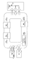
FIG. 9 is an explanatory view schematically showing hemoglobin metabolism in the human body.
Hemoglobin is a general term for proteins consisting of four subunits present in blood. This hemoglobin is combined with oxygen absorbed from, for example, the lungs to form oxygenated hemoglobin, as shown in FIG. 9, and oxygen is released in various parts of the body to react with carbon dioxide to form reduced hemoglobin. Moreover, when monosaccharides, such as glucose, are released into the blood from the liver or the like, hemoglobin binds to the monosaccharide and becomes glycated hemoglobin. Glycated hemoglobin also becomes reduced hemoglobin by releasing monosaccharides bound in various parts of the body. The released oxygen and monosaccharides are consumed as energy in various parts of the body. Reduced hemoglobin is decomposed into a compound called bilirubin (C 33 H 36 N 4 O 6 ) when its lifespan comes, metabolized by the liver, and excreted outside the body.
ここで、代謝経路中に存在する酸化ヘモグロビン、糖化ヘモグロビン及び還元ヘモグロビン等は、これらの物質が吸収する光の波長帯域が少しずつ異なるため、反射光中の特定の波長に着目することで、血液中の濃度を測定することができる。本開示の実施形態で示した500nm、540nm、580nm、620nm及び660nmの5種類の波長は、これらヘモグロビンの物質量を測定する際にも有用な波長帯域として機能する。従って、本開示の実施形態に係る測定装置1を利用して上述の5種類の波長における反射率を測定することで、酸化ヘモグロビン、糖化ヘモグロビン及び還元ヘモグロビンの存在量や濃度を算出することができる。これらの含有物質の存在量等をユーザに提供することで、ユーザは、目的に合った健康管理や体調異常の監視を行うことが可能となる。 Here, oxygenated hemoglobin, glycated hemoglobin, reduced hemoglobin, etc. present in the metabolic pathway are slightly different in the wavelength band of light absorbed by these substances, so by paying attention to a specific wavelength in the reflected light, blood The concentration in the medium can be measured. The five wavelengths of 500 nm, 540 nm, 580 nm, 620 nm, and 660 nm shown in the embodiments of the present disclosure function as useful wavelength bands when measuring the amount of these hemoglobin substances. Therefore, the abundance and concentration of oxyhemoglobin, glycated hemoglobin, and reduced hemoglobin can be calculated by measuring the reflectance at the above-described five wavelengths using the measurement apparatus 1 according to the embodiment of the present disclosure. . By providing the user with the abundance and the like of these contained substances, the user can perform health management and abnormal physical condition monitoring suitable for the purpose.
以下では、演算部203が、測定情報取得部201の取得した測定データを利用して、メラニン、還元ヘモグロビン、酸化ヘモグロビン、糖化ヘモグロビンの4種類の測定対象成分の濃度を算出する場合を例にとって、具体的に説明する。
In the following, the
ランベルト・ベールの法則より、測定された反射率をtとし、単位光路長あたりの濃度をcl(単位:mol/L・cm)とし、モル吸光係数をεとすると、以下の式102が成立する。 From the Lambert-Beer law, when the measured reflectance is t, the concentration per unit optical path length is cl (unit: mol / L · cm), and the molar extinction coefficient is ε, the following equation 102 holds. .
log(1/t)=ε・cl ・・・(式102) log (1 / t) = ε · cl (Formula 102)
また、メラニン、還元ヘモグロビン、酸化ヘモグロビン、糖化ヘモグロビンのモル吸光係数及び単位光路長あたりの濃度を以下のように表記するものとする。 In addition, the molar extinction coefficient and the concentration per unit optical path length of melanin, reduced hemoglobin, oxidized hemoglobin, and glycated hemoglobin are expressed as follows.
・メラニン
モル吸光係数:ε1、単位光路長あたりの濃度:Mn
・還元ヘモグロビン
モル吸光係数:ε2、単位光路長あたりの濃度:Hb
・酸化ヘモグロビン
モル吸光係数:ε3、単位光路長あたりの濃度:HbO2
・糖化ヘモグロビン
モル吸光係数:ε4、単位光路長あたりの濃度:HbAlc
Melanin molar extinction coefficient: ε1, concentration per unit optical path length: Mn
Reduced hemoglobin molar extinction coefficient: ε2, concentration per unit optical path length: Hb
Oxyhemoglobin molar absorption coefficient: ε3, concentration per unit optical path length: HbO2
Glycated hemoglobin molar extinction coefficient: ε4, concentration per unit optical path length: HbAlc
測定データにおけるある波長での反射率をSと表すこととし、人体内界面反射率をDと表すこととすると、上記式102より、着目している波長毎に以下の式103が成立することとなる。
If the reflectance at a certain wavelength in the measurement data is expressed as S and the human body interface reflectance is expressed as D, the following
Mn・ε1+Hb・ε2+HbO2・ε3+HbAlc・ε4+D=−logS
・・・(式103)
Mn · ε1 + Hb · ε2 + HbO2 · ε3 + HbAlc · ε4 + D = −logS
... (Formula 103)
従って、演算部203は、予め設定され記憶部205等に格納されている測定対象成分のモル吸光係数を参照するとともに、着目している波長(例えば、図4に示した5波長)についてそれぞれ上記式103を考慮することにより、一連の連立方程式を得ることができる。演算部203は、この連立方程式を解くことにより、測定対象成分の濃度(すなわち、単位光路長あたりの濃度)を算出することができる。
Accordingly, the
以上、添付図面を参照しながら本開示の好適な実施形態について詳細に説明したが、本開示の技術的範囲はかかる例に限定されない。本開示の技術分野における通常の知識を有する者であれば、特許請求の範囲に記載された技術的思想の範疇内において、各種の変更例または修正例に想到し得ることは明らかであり、これらについても、当然に本開示の技術的範囲に属するものと了解される。 The preferred embodiments of the present disclosure have been described in detail above with reference to the accompanying drawings, but the technical scope of the present disclosure is not limited to such examples. It is obvious that a person having ordinary knowledge in the technical field of the present disclosure can come up with various changes or modifications within the scope of the technical idea described in the claims. Of course, it is understood that it belongs to the technical scope of the present disclosure.
なお、以下のような構成も本開示の技術的範囲に属する。
(1)
測定対象物の載置された測定対象領域と対向する位置に設けられ、当該測定対象領域からの光が結像する受光素子と、
前記受光素子の周囲に配設され、前記測定対象物を測定するための光を射出する複数の発光素子と、
前記発光素子の上方に設けられ、当該発光素子から射出された放射発光を、前記測定対象領域へと導光する反射光学素子と、
を備え、
前記受光素子の受光面と、前記複数の発光素子の光射出面とは、互いに同一の平面上に位置しており、
前記複数の発光素子から射出された前記放射発光は前記反射光学素子により反射され、それぞれの前記発光素子からの前記放射発光の中心線が前記測定対象領域の略中心を通過する、測定装置。
(2)
前記測定対象物の載置される前記測定対象領域には開口部が設けられており、
前記開口部の中心と前記受光素子との中心とが対向する、(1)に記載の測定装置。
(3)
前記複数の発光素子としてN個の発光素子が配設されており、
前記N個の発光素子から、M(M≦N)種類の波長の放射発光が射出される、(1)又は(2)に記載の測定装置。
(4)
前記測定対象物は、有機物である、(1)〜(3)の何れか1つに記載の測定装置。
(5)
前記有機物は、人間の皮膚である、(4)に記載の測定装置。
(6)
前記複数の発光素子の個数が、当該発光素子から射出される前記放射発光の波長の種類数よりも大きい場合、許容される波長幅の狭い波長から順に、前記放射発光の波長が選択される、(3)〜(5)の何れか1つに記載の測定装置。
(7)
前記受光素子が受光する前記測定対象物からの反射光の光量は、前記測定対象物として白色校正板を載置した場合の当該白色校正板からの反射光の光量を基準として、95%以上である、(1)〜(6)の何れか1つに記載の測定装置。
(8)
前記受光素子と前記測定対象物との間の離隔距離は、3±0.2mmであり、
前記受光素子の大きさが、10mm四方であり、
円形の前記開口部の大きさは、直径5±0.4mmである、(7)に記載の測定装置。
(9)
前記放射発光の開口数NAは、0.2であり、
前記反射光学素子の前記光射出面に対する設置角度は、51°である、(8)に記載の測定装置。
(10)
前記発光素子の個数は、8個であり、
前記発光素子から射出される前記放射発光の波長は、λ1:500±25nm、λ2:540±15nm、λ3:580nm±5nm、λ4:620±15nm、及び、λ5:660±15nmの5種類であり、
λ1とλ2の波長をそれぞれ射出する前記発光素子が、1つずつ設けられ、
λ3〜λ5の波長をそれぞれ射出する前記発光素子が、2つずつ設けられる、(9)に記載の測定装置。
(11)
測定対象物の載置された測定対象領域と対向する位置に設けられ、当該測定対象領域からの光が結像する受光素子の周囲に配設され、前記測定対象物を測定するための光を射出する複数の発光素子から、前記測定対象物を測定するための光を射出させることと、
前記複数の発光素子から射出されたそれぞれの放射発光を、当該放射発光の中心線が前記測定対象領域の略中心を通過するように、前記発光素子の上方に設けられた反射光学素子により前記測定対象領域へと導光することと、
前記測定対象領域からの反射光を前記受光素子で受光することと、
を含み、
前記受光素子の受光面と、前記複数の発光素子の光射出面とは、互いに同一の平面上に位置している、測定方法。
(12)
測定対象物の載置された測定対象領域と対向する位置に設けられ、当該測定対象領域からの光が結像する受光素子と、前記受光素子の周囲に配設され、前記測定対象物を測定するための光を射出する複数の発光素子と、前記発光素子の上方に設けられ、当該発光素子から射出された放射発光を、前記測定対象領域へと導光する反射光学素子と、を備え、前記受光素子の受光面と、前記複数の発光素子の光射出面とは、互いに同一の平面上に位置しており、前記複数の発光素子から射出された前記光は前記反射光学素子により反射され、それぞれの前記発光素子からの前記放射発光の中心線が前記測定対象領域の略中心を通過する測定装置において、前記受光素子が受光する前記測定対象物からの反射光の光量の最低値を設定することと、
前記受光素子の大きさを、前記反射光の光量の最低値に基づいて設定するとともに、前記測定対象領域の大きさを、前記受光素子に求められる信号雑音比と設定した前記反射光の光量の最低値とに基づいて設定するとともに、前記受光素子と前記測定対象物との間の離隔距離を、前記受光素子への入射光量と前記反射光の光量の最低値とに基づいて設定することと、
を含む、パラメータの設定方法。
The following configurations also belong to the technical scope of the present disclosure.
(1)
A light receiving element that is provided at a position facing the measurement target region on which the measurement target is placed, and on which light from the measurement target region is imaged;
A plurality of light emitting elements disposed around the light receiving element and emitting light for measuring the measurement object;
A reflective optical element that is provided above the light emitting element and guides radiated light emitted from the light emitting element to the measurement target region;
With
The light receiving surface of the light receiving element and the light emitting surface of the plurality of light emitting elements are located on the same plane,
The measuring apparatus in which the radiated light emitted from the plurality of light emitting elements is reflected by the reflective optical element, and a center line of the radiated light from each of the light emitting elements passes through a substantially center of the measurement target region.
(2)
An opening is provided in the measurement target region where the measurement target is placed,
The measuring apparatus according to (1), wherein a center of the opening and a center of the light receiving element face each other.
(3)
N light emitting elements are disposed as the plurality of light emitting elements,
The measuring apparatus according to (1) or (2), wherein radiation emission of M (M ≦ N) types of wavelengths is emitted from the N light emitting elements.
(4)
The measurement apparatus according to any one of (1) to (3), wherein the measurement object is an organic substance.
(5)
The measuring apparatus according to (4), wherein the organic matter is human skin.
(6)
When the number of the plurality of light emitting elements is larger than the number of types of wavelengths of the emitted light emitted from the light emitting elements, the wavelengths of the emitted light are selected in order from a wavelength having a narrower allowable wavelength range. (3) The measuring device according to any one of (5).
(7)
The amount of reflected light from the measurement object received by the light receiving element is 95% or more based on the amount of reflected light from the white calibration plate when a white calibration plate is placed as the measurement object. The measuring apparatus according to any one of (1) to (6).
(8)
The separation distance between the light receiving element and the measurement object is 3 ± 0.2 mm,
The size of the light receiving element is 10 mm square,
The measurement device according to (7), wherein the circular opening has a diameter of 5 ± 0.4 mm.
(9)
The numerical aperture NA of the radiant emission is 0.2,
The measuring apparatus according to (8), wherein an installation angle of the reflective optical element with respect to the light exit surface is 51 °.
(10)
The number of the light emitting elements is eight,
The wavelengths of the emitted radiation emitted from the light emitting element are λ 1 : 500 ± 25 nm, λ 2 : 540 ± 15 nm, λ 3 : 580 nm ± 5 nm, λ 4 : 620 ± 15 nm, and λ 5 : 660 ± 15 nm. There are five types of
Each of the light emitting elements that respectively emit the wavelengths λ 1 and λ 2 is provided,
The measuring apparatus according to (9), wherein two each of the light emitting elements that respectively emit wavelengths of λ 3 to λ 5 are provided.
(11)
It is provided at a position facing the measurement target region on which the measurement target is placed, and is disposed around a light receiving element on which light from the measurement target region is imaged. Light for measuring the measurement target is provided. Emitting light for measuring the measurement object from a plurality of light emitting elements to be emitted;
Each of the radiated light emitted from the plurality of light emitting elements is measured by a reflective optical element provided above the light emitting element so that the center line of the radiated light passes through the approximate center of the measurement target region. Guiding light to the target area;
Receiving reflected light from the region to be measured by the light receiving element;
Including
The measurement method, wherein a light receiving surface of the light receiving element and a light emitting surface of the plurality of light emitting elements are positioned on the same plane.
(12)
A light receiving element provided at a position facing a measurement target region on which the measurement target is placed, and a light receiving element that forms an image of light from the measurement target region, and disposed around the light receiving element, measures the measurement target. A plurality of light emitting elements that emit light for performing, and a reflective optical element that is provided above the light emitting elements and guides radiated light emitted from the light emitting elements to the measurement target region, The light receiving surfaces of the light receiving elements and the light emitting surfaces of the plurality of light emitting elements are located on the same plane, and the light emitted from the plurality of light emitting elements is reflected by the reflective optical element. In the measurement apparatus in which the center line of the radiated light from each of the light emitting elements passes through the approximate center of the measurement target region, the minimum value of the amount of reflected light from the measurement target received by the light receiving element is set. To do
The size of the light receiving element is set based on the minimum value of the light amount of the reflected light, and the size of the measurement target region is set to a signal-to-noise ratio required for the light receiving element and the light amount of the reflected light set. And setting the separation distance between the light receiving element and the measurement object based on the minimum amount of incident light to the light receiving element and the amount of reflected light. ,
How to set parameters, including
1 測定装置
11 筺体
13 開口部
100 光学系
101 受光素子
103 発光素子
105 反射光学素子(ミラー)
200 演算処理装置
201 測定情報取得部
203 演算部
205 記憶部
DESCRIPTION OF SYMBOLS 1
200
Claims (11)
前記測定対象領域と対向する位置に前記開口部から離隔して設けられ、当該測定対象領域からの光が結像するものであり、前記開口部の開口面積よりも大きな受光面積を有し、前記測定対象物からの反射光の光量が、前記測定対象物として白色校正板を載置した場合の当該白色校正板からの反射光の光量を基準として、所定の割合以上となる受光素子と、
前記受光素子の周囲に配設され、前記測定対象物を測定するための所定の開口数を有する光を射出する複数の発光素子と、
前記発光素子の上方に設けられ、当該発光素子から射出された放射発光を、前記測定対象領域へと導光する反射光学素子と、
を備え、
前記受光素子が受光する前記反射光の光量に応じた前記開口面積を有する前記開口部の中心と前記受光素子との中心とが、前記受光素子が受光する前記反射光の光量に応じた離隔距離で対向しており、かつ、前記受光素子の受光面と、前記複数の発光素子の光射出面とは、互いに同一の平面上に位置しており、
前記複数の発光素子から射出された前記放射発光は、前記離隔距離及び前記放射発光の開口数に応じた、前記発光素子の光射出面と前記反射光学素子の反射面とのなす角を有する前記反射光学素子により反射され、それぞれの前記発光素子からの前記放射発光の中心線が前記測定対象領域の略中心を通過する、測定装置。 An opening having a predetermined opening area provided in a measurement target region on which the measurement target is placed;
Provided spaced from said opening at a position opposite to the measurement target region, which light from the measurement target region is imaged, have a large light-receiving area than the opening area of the opening, the A light receiving element in which the amount of reflected light from the measurement object is a predetermined ratio or more based on the amount of reflected light from the white calibration plate when the white calibration plate is placed as the measurement object ;
A plurality of light emitting elements that are arranged around the light receiving element and emit light having a predetermined numerical aperture for measuring the measurement object;
A reflective optical element that is provided above the light emitting element and guides radiated light emitted from the light emitting element to the measurement target region;
With
The center of the opening having the opening area corresponding to the amount of the reflected light received by the light receiving element and the center of the light receiving element are separated by the amount of the reflected light received by the light receiving element. And the light receiving surface of the light receiving element and the light emitting surface of the plurality of light emitting elements are located on the same plane,
The radiated light emitted from the plurality of light emitting elements has an angle formed by a light emitting surface of the light emitting element and a reflective surface of the reflective optical element according to the separation distance and the numerical aperture of the radiated light. A measuring apparatus that is reflected by a reflective optical element, and the center line of the emitted light from each of the light emitting elements passes through the approximate center of the measurement target region.
前記N個の発光素子から、M(M≦N)種類の波長の前記放射発光が射出される、請求項1に記載の測定装置。 N light emitting elements are disposed as the plurality of light emitting elements,
The measuring apparatus according to claim 1, wherein the radiant emission of M (M ≦ N) types of wavelengths is emitted from the N light emitting elements.
前記受光素子の大きさが、10mm四方であり、
前記測定対象物の載置される前記測定対象領域に設けられる円形の開口部の大きさは、直径5±0.4mmである、請求項6に記載の測定装置。 The separation distance between the light receiving element and the measurement object is 3 ± 0.2 mm,
The size of the light receiving element is 10 mm square,
The measuring apparatus according to claim 6, wherein a size of the circular opening provided in the measurement target region on which the measurement target is placed has a diameter of 5 ± 0.4 mm.
前記反射光学素子の前記光射出面に対する設置角度は、51°である、請求項7に記載の測定装置。 The numerical aperture NA of the radiant emission is 0.2,
The measuring apparatus according to claim 7, wherein an installation angle of the reflective optical element with respect to the light exit surface is 51 °.
前記発光素子から射出される前記放射発光の波長は、λ1:500±25nm、λ2:540±15nm、λ3:580nm±5nm、λ4:620±15nm、及び、λ5:660±15nmの5種類であり、
λ1とλ2の波長をそれぞれ射出する前記発光素子が、1つずつ設けられ、
λ3〜λ5の波長をそれぞれ射出する前記発光素子が、2つずつ設けられる、請求項8に記載の測定装置。 The number of the light emitting elements is eight,
The wavelengths of the emitted radiation emitted from the light emitting element are λ 1 : 500 ± 25 nm, λ 2 : 540 ± 15 nm, λ 3 : 580 nm ± 5 nm, λ 4 : 620 ± 15 nm, and λ 5 : 660 ± 15 nm. There are five types of
Each of the light emitting elements that respectively emit the wavelengths λ 1 and λ 2 is provided,
The measurement apparatus according to claim 8, wherein two each of the light emitting elements that respectively emit wavelengths of λ 3 to λ 5 are provided.
前記複数の発光素子から射出されたそれぞれの放射発光を、当該放射発光の中心線が前記測定対象領域の略中心を通過するように、前記発光素子の上方に設けられており、前記発光素子の光射出面とのなす角が、前記開口部と前記受光素子との間の離隔距離及び前記放射発光の開口数に応じて設定された反射光学素子により前記測定対象領域へと導光することと、
前記測定対象領域からの反射光を前記受光素子で受光することと、
を含み、
前記受光素子が受光する前記反射光の光量に応じた前記開口面積を有する前記開口部の中心と前記受光素子との中心とが、前記受光素子が受光する前記反射光の光量に応じた離隔距離で対向しており、かつ、前記受光素子の受光面と、前記複数の発光素子の光射出面とは、互いに同一の平面上に位置している、測定方法。 Separated from the opening having a predetermined opening area provided in the measurement target region on which the measurement target is placed, provided at a position facing the measurement target, and light from the measurement target region is transmitted is intended for imaging, have a large light-receiving area than the opening area of the opening, the amount of reflected light from the measurement object, the white in the case of placing the white calibration plate as the object to be measured A plurality of light emitting elements that are arranged around a light receiving element having a predetermined ratio or more with respect to the amount of reflected light from the calibration plate and emit light having a predetermined numerical aperture for measuring the measurement object And emitting light for measuring the measurement object;
The radiated light emitted from the plurality of light emitting elements is provided above the light emitting element so that the center line of the radiated light passes through the approximate center of the measurement target region . The angle formed by the light exit surface is guided to the measurement target region by a reflective optical element set in accordance with a separation distance between the opening and the light receiving element and a numerical aperture of the radiation emission ; ,
Receiving reflected light from the region to be measured by the light receiving element;
Including
The center of the opening having the opening area corresponding to the amount of the reflected light received by the light receiving element and the center of the light receiving element are separated by the amount of the reflected light received by the light receiving element. And the light receiving surfaces of the light receiving elements and the light emitting surfaces of the plurality of light emitting elements are located on the same plane.
前記測定対象領域の大きさを、前記受光素子に求められる信号雑音比と設定した前記反射光の光量の最低値とに基づいて設定するとともに、前記受光素子と前記測定対象物との間の離隔距離を、前記受光素子への入射光量と前記反射光の光量の最低値とに基づいて設定することと、
を含む、パラメータの設定方法。 Provided in the measurement target region where the measurement target is placed, provided with an opening having a predetermined opening area, and spaced apart from the opening at a position facing the measurement target region, from the measurement target region are those in which light is imaged, have a large light-receiving area than the opening area of the opening, the amount of reflected light from the measurement object, when placing the white calibration plate as the object to be measured A light receiving element having a predetermined ratio or more with respect to the amount of reflected light from the white calibration plate, and light having a predetermined numerical aperture for measuring the measurement object, which is disposed around the light receiving element. A plurality of light emitting elements that emit light, and a reflective optical element that is provided above the light emitting elements and guides radiated light emitted from the light emitting elements to the measurement target region, the light receiving element The amount of reflected light received Flip was the center of the center and the light receiving element of the opening having the opening area faces at distance corresponding to the amount of the reflected light which the light receiving element receives light, and the light receiving element The light receiving surface and the light emitting surfaces of the plurality of light emitting elements are located on the same plane, and the light emitted from the plurality of light emitting elements is reflected by the light emitting surface of the light emitting element and the reflection. The angle formed by the reflection surface of the optical element is reflected by the reflective optical element set according to the separation distance and the numerical aperture of the radiated light, and the center line of the radiated light from each of the light emitting elements is measured. In the measurement apparatus that passes through the approximate center of the target region, a minimum value of the amount of reflected light from the measurement object received by the light receiving element is set, and the light reception is performed based on the set minimum value of the amount of reflected light. Determine the size of the element And that,
The size of the measurement target region is set based on the signal-to-noise ratio required for the light receiving element and the set minimum value of the amount of reflected light, and the distance between the light receiving element and the measurement target is set. Setting the distance based on the amount of incident light to the light receiving element and the minimum value of the amount of reflected light;
How to set parameters, including
Priority Applications (4)
| Application Number | Priority Date | Filing Date | Title |
|---|---|---|---|
| JP2011247571A JP5966325B2 (en) | 2011-11-11 | 2011-11-11 | Measuring apparatus, measuring method and parameter setting method |
| CN201280053504.9A CN104024828B (en) | 2011-11-11 | 2012-09-10 | Measurement apparatus, measuring method and parameter setting method |
| US14/356,020 US9566005B2 (en) | 2011-11-11 | 2012-09-10 | Measuring apparatus, measuring method, and parameter setting method |
| PCT/JP2012/073035 WO2013069367A1 (en) | 2011-11-11 | 2012-09-10 | Measuring apparatus, measuring method, and parameter setting method |
Applications Claiming Priority (1)
| Application Number | Priority Date | Filing Date | Title |
|---|---|---|---|
| JP2011247571A JP5966325B2 (en) | 2011-11-11 | 2011-11-11 | Measuring apparatus, measuring method and parameter setting method |
Publications (3)
| Publication Number | Publication Date |
|---|---|
| JP2013104728A JP2013104728A (en) | 2013-05-30 |
| JP2013104728A5 JP2013104728A5 (en) | 2014-12-18 |
| JP5966325B2 true JP5966325B2 (en) | 2016-08-10 |
Family
ID=48289753
Family Applications (1)
| Application Number | Title | Priority Date | Filing Date |
|---|---|---|---|
| JP2011247571A Expired - Fee Related JP5966325B2 (en) | 2011-11-11 | 2011-11-11 | Measuring apparatus, measuring method and parameter setting method |
Country Status (4)
| Country | Link |
|---|---|
| US (1) | US9566005B2 (en) |
| JP (1) | JP5966325B2 (en) |
| CN (1) | CN104024828B (en) |
| WO (1) | WO2013069367A1 (en) |
Families Citing this family (4)
| Publication number | Priority date | Publication date | Assignee | Title |
|---|---|---|---|---|
| JP6323227B2 (en) * | 2013-12-16 | 2018-05-16 | ソニー株式会社 | Image analysis apparatus, image analysis method, program, and illumination apparatus |
| JP2015223404A (en) * | 2014-05-29 | 2015-12-14 | 京セラ株式会社 | Sensor and skin information detection method |
| JP6947551B2 (en) * | 2017-06-27 | 2021-10-13 | 花王株式会社 | Surface condition evaluation method |
| WO2023023753A1 (en) * | 2021-08-24 | 2023-03-02 | Macquarie Medical Systems Pty Ltd | Skin examination device |
Family Cites Families (13)
| Publication number | Priority date | Publication date | Assignee | Title |
|---|---|---|---|---|
| US4880304A (en) | 1987-04-01 | 1989-11-14 | Nippon Colin Co., Ltd. | Optical sensor for pulse oximeter |
| US5638818A (en) * | 1991-03-21 | 1997-06-17 | Masimo Corporation | Low noise optical probe |
| US7299080B2 (en) | 1999-10-08 | 2007-11-20 | Sensys Medical, Inc. | Compact apparatus for noninvasive measurement of glucose through near-infrared spectroscopy |
| AU2001230580A1 (en) * | 2000-02-03 | 2001-08-14 | Hamamatsu Photonics K.K. | Noninvasion biological optical measuring instrument, measured portion holding device, and method for manufacturing the same |
| US7606608B2 (en) | 2000-05-02 | 2009-10-20 | Sensys Medical, Inc. | Optical sampling interface system for in-vivo measurement of tissue |
| US6588118B2 (en) | 2001-10-10 | 2003-07-08 | Abb Inc. | Non-contact sheet sensing system and related method |
| JP2007252774A (en) * | 2006-03-24 | 2007-10-04 | Kyocera Corp | Optical tomography imaging apparatus |
| JP2008086705A (en) * | 2006-10-05 | 2008-04-17 | Sanyo Electric Co Ltd | Measurement assisting material, and optical measuring method using the same |
| KR20090127377A (en) * | 2007-04-03 | 2009-12-10 | 무토 고교 가부시키가이샤 | Spectrophotometer and method |
| JP2008289808A (en) * | 2007-05-28 | 2008-12-04 | Panasonic Electric Works Co Ltd | Sensing apparatus for biological surface tissue |
| US8452364B2 (en) * | 2007-12-28 | 2013-05-28 | Covidien LLP | System and method for attaching a sensor to a patient's skin |
| CN103542935B (en) * | 2008-03-19 | 2016-02-03 | 超级医药成像有限公司 | For the Miniaturized multi-spectral that real-time tissue oxygenation is measured |
| US8789969B2 (en) * | 2010-08-17 | 2014-07-29 | GE Lighting Solutions, LLC | Compact LED light engine with reflector cups and highly directional lamps using same |
-
2011
- 2011-11-11 JP JP2011247571A patent/JP5966325B2/en not_active Expired - Fee Related
-
2012
- 2012-09-10 WO PCT/JP2012/073035 patent/WO2013069367A1/en active Application Filing
- 2012-09-10 US US14/356,020 patent/US9566005B2/en active Active
- 2012-09-10 CN CN201280053504.9A patent/CN104024828B/en active Active
Also Published As
| Publication number | Publication date |
|---|---|
| WO2013069367A1 (en) | 2013-05-16 |
| US20140303505A1 (en) | 2014-10-09 |
| CN104024828B (en) | 2017-08-25 |
| JP2013104728A (en) | 2013-05-30 |
| US9566005B2 (en) | 2017-02-14 |
| CN104024828A (en) | 2014-09-03 |
Similar Documents
| Publication | Publication Date | Title |
|---|---|---|
| US8605284B2 (en) | Measurement device and measurement method | |
| US20220225886A1 (en) | Optical vital signs sensor | |
| CA2605467C (en) | Systems and methods for correcting optical reflectance measurements | |
| JP7004575B2 (en) | Optical physiologic measurement system | |
| JP4701468B2 (en) | Biological information measuring device | |
| US20070203405A1 (en) | Instrument For Noninvasively Measuring Blood Sugar Level | |
| US7710550B2 (en) | Oximeter for spectro-photometric in-vitro determination of hemoglobin derivatives | |
| US8306594B2 (en) | Transmission fluorometer | |
| JP5966325B2 (en) | Measuring apparatus, measuring method and parameter setting method | |
| US20130289414A1 (en) | Combined absorption-reflection based instrument and technique to measure antioxidants (including carotenoids) in human tissue | |
| US20200305776A1 (en) | Frequency domain-based multi-wavelength bio-signal analyzing apparatus and method thereof | |
| KR101919229B1 (en) | Apparatus and method for measuring a biometrics information | |
| JP2008157809A (en) | Laser output control device and optical measuring unit | |
| JP6885231B2 (en) | Detection device and biological information measuring device | |
| JP2010194000A (en) | Optical sensor and measurement system | |
| JP2008289808A (en) | Sensing apparatus for biological surface tissue | |
| Lisenko et al. | Noninvasive fast analysis of hemoglobin levels in blood using a fiber optic spectrophotometer | |
| JP2008157832A (en) | Optical measuring instrument for living body | |
| JP6850257B2 (en) | Non-invasive method for measuring physiological parameters via confocal spectroscopy | |
| WO2022067170A1 (en) | Broadband multispectral diagnostic systems and methods | |
| JP2014226337A (en) | Measuring device | |
| JP2014174140A (en) | Optical probe holder and detector |
Legal Events
| Date | Code | Title | Description |
|---|---|---|---|
| A521 | Request for written amendment filed |
Free format text: JAPANESE INTERMEDIATE CODE: A523 Effective date: 20141031 |
|
| A621 | Written request for application examination |
Free format text: JAPANESE INTERMEDIATE CODE: A621 Effective date: 20141031 |
|
| A131 | Notification of reasons for refusal |
Free format text: JAPANESE INTERMEDIATE CODE: A131 Effective date: 20151027 |
|
| A521 | Request for written amendment filed |
Free format text: JAPANESE INTERMEDIATE CODE: A523 Effective date: 20151218 |
|
| A131 | Notification of reasons for refusal |
Free format text: JAPANESE INTERMEDIATE CODE: A131 Effective date: 20160202 |
|
| A521 | Request for written amendment filed |
Free format text: JAPANESE INTERMEDIATE CODE: A523 Effective date: 20160328 |
|
| TRDD | Decision of grant or rejection written | ||
| A01 | Written decision to grant a patent or to grant a registration (utility model) |
Free format text: JAPANESE INTERMEDIATE CODE: A01 Effective date: 20160607 |
|
| A61 | First payment of annual fees (during grant procedure) |
Free format text: JAPANESE INTERMEDIATE CODE: A61 Effective date: 20160620 |
|
| R151 | Written notification of patent or utility model registration |
Ref document number: 5966325 Country of ref document: JP Free format text: JAPANESE INTERMEDIATE CODE: R151 |
|
| R250 | Receipt of annual fees |
Free format text: JAPANESE INTERMEDIATE CODE: R250 |
|
| R250 | Receipt of annual fees |
Free format text: JAPANESE INTERMEDIATE CODE: R250 |
|
| LAPS | Cancellation because of no payment of annual fees |