JP5964162B2 - Encoder - Google Patents
Encoder Download PDFInfo
- Publication number
- JP5964162B2 JP5964162B2 JP2012159302A JP2012159302A JP5964162B2 JP 5964162 B2 JP5964162 B2 JP 5964162B2 JP 2012159302 A JP2012159302 A JP 2012159302A JP 2012159302 A JP2012159302 A JP 2012159302A JP 5964162 B2 JP5964162 B2 JP 5964162B2
- Authority
- JP
- Japan
- Prior art keywords
- phase
- signal
- sine wave
- light receiving
- sensing elements
- Prior art date
- Legal status (The legal status is an assumption and is not a legal conclusion. Google has not performed a legal analysis and makes no representation as to the accuracy of the status listed.)
- Active
Links
- 238000001514 detection method Methods 0.000 claims description 43
- 238000000034 method Methods 0.000 claims description 16
- 230000005674 electromagnetic induction Effects 0.000 claims description 3
- 238000010586 diagram Methods 0.000 description 28
- 230000004048 modification Effects 0.000 description 11
- 238000012986 modification Methods 0.000 description 11
- 230000003287 optical effect Effects 0.000 description 2
- 238000001914 filtration Methods 0.000 description 1
Images


Classifications
-
- G—PHYSICS
- G01—MEASURING; TESTING
- G01D—MEASURING NOT SPECIALLY ADAPTED FOR A SPECIFIC VARIABLE; ARRANGEMENTS FOR MEASURING TWO OR MORE VARIABLES NOT COVERED IN A SINGLE OTHER SUBCLASS; TARIFF METERING APPARATUS; MEASURING OR TESTING NOT OTHERWISE PROVIDED FOR
- G01D5/00—Mechanical means for transferring the output of a sensing member; Means for converting the output of a sensing member to another variable where the form or nature of the sensing member does not constrain the means for converting; Transducers not specially adapted for a specific variable
- G01D5/12—Mechanical means for transferring the output of a sensing member; Means for converting the output of a sensing member to another variable where the form or nature of the sensing member does not constrain the means for converting; Transducers not specially adapted for a specific variable using electric or magnetic means
- G01D5/244—Mechanical means for transferring the output of a sensing member; Means for converting the output of a sensing member to another variable where the form or nature of the sensing member does not constrain the means for converting; Transducers not specially adapted for a specific variable using electric or magnetic means influencing characteristics of pulses or pulse trains; generating pulses or pulse trains
- G01D5/24471—Error correction
- G01D5/24476—Signal processing
-
- G—PHYSICS
- G01—MEASURING; TESTING
- G01D—MEASURING NOT SPECIALLY ADAPTED FOR A SPECIFIC VARIABLE; ARRANGEMENTS FOR MEASURING TWO OR MORE VARIABLES NOT COVERED IN A SINGLE OTHER SUBCLASS; TARIFF METERING APPARATUS; MEASURING OR TESTING NOT OTHERWISE PROVIDED FOR
- G01D5/00—Mechanical means for transferring the output of a sensing member; Means for converting the output of a sensing member to another variable where the form or nature of the sensing member does not constrain the means for converting; Transducers not specially adapted for a specific variable
- G01D5/12—Mechanical means for transferring the output of a sensing member; Means for converting the output of a sensing member to another variable where the form or nature of the sensing member does not constrain the means for converting; Transducers not specially adapted for a specific variable using electric or magnetic means
- G01D5/244—Mechanical means for transferring the output of a sensing member; Means for converting the output of a sensing member to another variable where the form or nature of the sensing member does not constrain the means for converting; Transducers not specially adapted for a specific variable using electric or magnetic means influencing characteristics of pulses or pulse trains; generating pulses or pulse trains
- G01D5/24428—Error prevention
- G01D5/24433—Error prevention by mechanical means
- G01D5/24438—Special design of the sensing element or scale
-
- G—PHYSICS
- G01—MEASURING; TESTING
- G01D—MEASURING NOT SPECIALLY ADAPTED FOR A SPECIFIC VARIABLE; ARRANGEMENTS FOR MEASURING TWO OR MORE VARIABLES NOT COVERED IN A SINGLE OTHER SUBCLASS; TARIFF METERING APPARATUS; MEASURING OR TESTING NOT OTHERWISE PROVIDED FOR
- G01D5/00—Mechanical means for transferring the output of a sensing member; Means for converting the output of a sensing member to another variable where the form or nature of the sensing member does not constrain the means for converting; Transducers not specially adapted for a specific variable
- G01D5/26—Mechanical means for transferring the output of a sensing member; Means for converting the output of a sensing member to another variable where the form or nature of the sensing member does not constrain the means for converting; Transducers not specially adapted for a specific variable characterised by optical transfer means, i.e. using infrared, visible, or ultraviolet light
- G01D5/32—Mechanical means for transferring the output of a sensing member; Means for converting the output of a sensing member to another variable where the form or nature of the sensing member does not constrain the means for converting; Transducers not specially adapted for a specific variable characterised by optical transfer means, i.e. using infrared, visible, or ultraviolet light with attenuation or whole or partial obturation of beams of light
- G01D5/34—Mechanical means for transferring the output of a sensing member; Means for converting the output of a sensing member to another variable where the form or nature of the sensing member does not constrain the means for converting; Transducers not specially adapted for a specific variable characterised by optical transfer means, i.e. using infrared, visible, or ultraviolet light with attenuation or whole or partial obturation of beams of light the beams of light being detected by photocells
- G01D5/347—Mechanical means for transferring the output of a sensing member; Means for converting the output of a sensing member to another variable where the form or nature of the sensing member does not constrain the means for converting; Transducers not specially adapted for a specific variable characterised by optical transfer means, i.e. using infrared, visible, or ultraviolet light with attenuation or whole or partial obturation of beams of light the beams of light being detected by photocells using displacement encoding scales
- G01D5/34707—Scales; Discs, e.g. fixation, fabrication, compensation
-
- G—PHYSICS
- G01—MEASURING; TESTING
- G01D—MEASURING NOT SPECIALLY ADAPTED FOR A SPECIFIC VARIABLE; ARRANGEMENTS FOR MEASURING TWO OR MORE VARIABLES NOT COVERED IN A SINGLE OTHER SUBCLASS; TARIFF METERING APPARATUS; MEASURING OR TESTING NOT OTHERWISE PROVIDED FOR
- G01D5/00—Mechanical means for transferring the output of a sensing member; Means for converting the output of a sensing member to another variable where the form or nature of the sensing member does not constrain the means for converting; Transducers not specially adapted for a specific variable
- G01D5/26—Mechanical means for transferring the output of a sensing member; Means for converting the output of a sensing member to another variable where the form or nature of the sensing member does not constrain the means for converting; Transducers not specially adapted for a specific variable characterised by optical transfer means, i.e. using infrared, visible, or ultraviolet light
- G01D5/32—Mechanical means for transferring the output of a sensing member; Means for converting the output of a sensing member to another variable where the form or nature of the sensing member does not constrain the means for converting; Transducers not specially adapted for a specific variable characterised by optical transfer means, i.e. using infrared, visible, or ultraviolet light with attenuation or whole or partial obturation of beams of light
- G01D5/34—Mechanical means for transferring the output of a sensing member; Means for converting the output of a sensing member to another variable where the form or nature of the sensing member does not constrain the means for converting; Transducers not specially adapted for a specific variable characterised by optical transfer means, i.e. using infrared, visible, or ultraviolet light with attenuation or whole or partial obturation of beams of light the beams of light being detected by photocells
- G01D5/36—Forming the light into pulses
Landscapes
- Physics & Mathematics (AREA)
- General Physics & Mathematics (AREA)
- Engineering & Computer Science (AREA)
- Signal Processing (AREA)
- Optical Transform (AREA)
- Transmission And Conversion Of Sensor Element Output (AREA)
- Optical Communication System (AREA)
Description
本発明はエンコーダ関する。 The present invention relates to an encoder.
光学式のエンコーダでは、4相正弦波からA相及びB相の波形を取得し、これらを描画して得られるリサージュ曲線を基に、位置を検出する手法がしばしば用いられる。この手法で得られるリサージュ曲線には、3次以上の高調波による位置誤差が生じる問題が知られている。 In an optical encoder, a method of detecting a position based on a Lissajous curve obtained by acquiring A-phase and B-phase waveforms from a four-phase sine wave and drawing them is often used. The Lissajous curve obtained by this method is known to cause a position error due to higher harmonics of the third order or higher.
位置誤差を抑制する手法として、例えば、高調波の成分を光学的にフィルタすることで、3次以上の高調波を抑制する手法が、既に提案されている(特許文献1)。 As a technique for suppressing the position error, for example, a technique for suppressing higher-order harmonics by optically filtering harmonic components has already been proposed (Patent Document 1).
また、他の手法として、高調波の成分を幾何学的に解析して取り除く手法(特許文献2)が提案されている。この手法では、演算回路により演算を行うことで、効率的に3次以上の高調波を除去することができる。 As another technique, a technique (Patent Document 2) has been proposed in which harmonic components are geometrically analyzed and removed. In this method, the third and higher harmonics can be efficiently removed by performing an operation using an arithmetic circuit.
ところが、発明者は、上述の手法には、以下の問題点が有ることを見出した。特許文献1に記載の手法は、既に信号に含まれている高次高調波の影響を抑制するものである。そのため、3次以上の高調波の影響がある程度残存してしまう。
However, the inventor has found that the above-described method has the following problems. The technique described in
また、特許文献2に記載の手法では、複雑な演算が必要であるため、高機能な演算回路が必要となる。さらに、演算時間による遅延が生じるため、高調波の変動に追随することができず、高調波の影響を除去できない事態が生じる。
Further, the technique described in
以上のように、上述の手法では、3次以上の高調波の変動に追随しつつ効率的に3次以上の高調波の影響を除去することができるエンコーダを実現することはできない。 As described above, the above-described method cannot realize an encoder that can efficiently remove the influence of third-order or higher harmonics while following fluctuations of third-order or higher harmonics.
本発明の第1の態様であるエンコーダは、スケールからの信号を読み取り、基本波のそれぞれの位相が2π/N(Nは、5以上の整数)ずつ異なるN相正弦波信号を出力する検知部と、前記N相正弦波信号のそれぞれに応じてA相及びB相からなる2相正弦波信号を出力する演算部と、を備え、mを0≦m≦N−1の整数、iを虚数単位、S2πm/Nを前記N相正弦波のm番目の相の正弦波信号として、前記A相及びB相は、以下の式(1)で表されるものである。

本発明の第2の態様であるエンコーダは、上記のエンコーダであって、前記N相正弦波信号に含まれるn(nは、1≦n≦Nの整数)次の波の振幅をCn、高次高調波の最大次数をh(hは、正の整数)、前記スケールの繰り返し周期に相当する距離をL、前記n次の波の初期位相をθn、ノイズをDとして、前記N相正弦波のm番目の相の正弦波信号S2πm/Nは、以下の式(2)で表されるものである。
本発明の第3の態様であるエンコーダは、上記のエンコーダであって、前記式(2)においてN>h+2を満たすものである。 An encoder according to a third aspect of the present invention is the encoder described above, and satisfies N> h + 2 in the equation (2).
本発明の第4の態様であるエンコーダは、上記のエンコーダであって、前記N相正弦波信号は、第1〜第8の正弦波信号からなる8相正弦波信号であり、前記第2〜8の正弦波信号は、それぞれm=0〜7の場合に対応するものである。 An encoder according to a fourth aspect of the present invention is the encoder described above, wherein the N-phase sine wave signal is an 8-phase sine wave signal including first to eighth sine wave signals, and The sine wave signals of 8 correspond to cases where m = 0 to 7, respectively.
本発明の第5の態様であるエンコーダは、上記のエンコーダであって、前記演算部は、第1の信号から第2の信号を減算した信号を出力する第1の減算器と、第3の信号から第2の信号を減算した信号を出力する第2の減算器と、第3の信号から第4の信号を減算した信号を出力する第3の減算器と、第1の信号から第4の信号を減算した信号を出力する第4の減算器と、前記第1の正弦波信号と前記第1の減算器の出力信号とを加算する第1の加算器と、前記第3の正弦波信号と前記第2の減算器の出力信号とを加算する第2の加算器と、前記第5の正弦波信号と前記第3の減算器の出力信号とを加算する第3の加算器と、前記第7の正弦波信号と前記第4の減算器の出力信号とを加算する第4の加算器と、前記第1の加算器の出力信号から前記第3の加算器の出力信号を減算した信号を前記A相として出力する第5の減算器と、前記第2の加算器の出力信号から前記第4の加算器の出力信号を減算した信号を前記B相として出力する第6の減算器と、を備えるものである。 An encoder according to a fifth aspect of the present invention is the encoder described above, wherein the calculation unit includes a first subtracter that outputs a signal obtained by subtracting the second signal from the first signal, A second subtractor that outputs a signal obtained by subtracting the second signal from the signal; a third subtracter that outputs a signal obtained by subtracting the fourth signal from the third signal; and a fourth subtracter from the first signal. A fourth subtractor that outputs a signal obtained by subtracting the first signal, a first adder that adds the first sine wave signal and the output signal of the first subtractor, and the third sine wave. A second adder for adding the signal and the output signal of the second subtractor; a third adder for adding the fifth sine wave signal and the output signal of the third subtractor; A fourth adder for adding the seventh sine wave signal and the output signal of the fourth subtractor; and an output signal of the first adder. A signal obtained by subtracting the output signal of the fourth adder from the output signal of the second adder; and a fifth subtractor that outputs a signal obtained by subtracting the output signal of the third adder as the A phase. And a sixth subtractor that outputs the signal as the B phase.
本発明の第6の態様であるエンコーダは、上記のエンコーダであって、前記第1〜8の正弦波信号のそれぞれの振幅は同じであり、前記第1の信号は、前記第2の正弦波信号を√2/2倍した信号であり、前記第2の信号は、前記第4の正弦波信号を√2/2倍した信号であり、前記第3の信号は、前記第6の正弦波信号を√2/2倍した信号であり、前記第4の信号は、前記第8の正弦波信号を√2/2倍した信号であるものである。 An encoder according to a sixth aspect of the present invention is the encoder described above, wherein the first to eighth sine wave signals have the same amplitude, and the first signal is the second sine wave. The second signal is a signal obtained by multiplying the fourth sine wave signal by √2 / 2, and the third signal is the sixth sine wave. The fourth signal is a signal obtained by multiplying the eighth sine wave signal by √2 / 2.
本発明の第7の態様であるエンコーダは、上記のエンコーダであって、前記演算部は、前記第2の正弦波信号を√2/2倍した信号を前記第1の信号として出力する第1の増幅器と、前記第4の正弦波信号を√2/2倍した信号を前記第2の信号として出力する第2の増幅器と、前記第6の正弦波信号を√2/2倍した信号を前記第3の信号として出力する第3の増幅器と、前記第8の正弦波信号を√2/2倍した信号を前記第4の信号として出力する第4の増幅器と、を更に備えるものである。 An encoder according to a seventh aspect of the present invention is the encoder described above, wherein the calculation unit outputs a signal obtained by multiplying the second sine wave signal by √2 / 2 as the first signal. A second amplifier that outputs a signal obtained by multiplying the fourth sine wave signal by √2 / 2 as the second signal, and a signal obtained by multiplying the sixth sine wave signal by √2 / 2. A third amplifier that outputs the third signal; and a fourth amplifier that outputs a signal obtained by multiplying the eighth sine wave signal by √2 / 2 as the fourth signal. .
本発明の第8の態様であるエンコーダは、上記のエンコーダであって、前記第2、4、6及び8の正弦波信号の振幅は、前記第1、3、5及び7の正弦波信号の振幅の√2/2倍であり、前記第1の信号は、前記第2の正弦波信号であり、前記第2の信号は、前記第4の正弦波信号であり、前記第3の信号は、前記第6の正弦波信号であり、前記第4の信号は、前記第8の正弦波信号であるものである。 An encoder according to an eighth aspect of the present invention is the encoder described above, wherein the amplitudes of the second, fourth, sixth and eighth sine wave signals are the same as the first, third, fifth and seventh sine wave signals. √2 / 2 times the amplitude, the first signal is the second sine wave signal, the second signal is the fourth sine wave signal, and the third signal is , The sixth sine wave signal, and the fourth signal is the eighth sine wave signal.
本発明の第9の態様であるエンコーダは、上記のエンコーダであって、前記検知部は、前記検知部の移動方向である第1の方向の長さが、前記スケールの1周期の長さと等しい1又は複数の検知領域を備え、前記検知領域は、前記スケールからの信号に応じて、それぞれ前記第1〜8の正弦波信号を出力する第1〜8の検知素子を備えるものである。 An encoder according to a ninth aspect of the present invention is the encoder described above, wherein the detection unit has a length in a first direction that is a moving direction of the detection unit equal to a length of one cycle of the scale. One or a plurality of detection areas are provided, and the detection areas include first to eighth detection elements that output the first to eighth sine wave signals, respectively, in accordance with a signal from the scale.
本発明の第10の態様であるエンコーダは、上記のエンコーダであって、前記第1〜8の検知素子は、それぞれ前記第1〜8の検知素子の面積に応じた振幅を有する前記第1〜8の正弦波信号を出力し、前記第1〜8の検知素子は、等しい面積を有するものである。 An encoder according to a tenth aspect of the present invention is the encoder described above, wherein the first to eighth detection elements have amplitudes corresponding to areas of the first to eighth detection elements, respectively. Eight sine wave signals are output, and the first to eighth sensing elements have the same area.
本発明の第11の態様であるエンコーダは、上記のエンコーダであって、前記第1〜8の検知素子は、同一の矩形形状であるものである。 An encoder according to an eleventh aspect of the present invention is the encoder described above, wherein the first to eighth detection elements have the same rectangular shape.
本発明の第12の態様であるエンコーダは、上記のエンコーダであって、前記第1〜8の検知素子は、前記第1の方向に並んで配置されるものである。 An encoder according to a twelfth aspect of the present invention is the encoder described above, wherein the first to eighth detection elements are arranged side by side in the first direction.
本発明の第13の態様であるエンコーダは、上記のエンコーダであって、前記検知領域は、前記第1、3、5及び7の検知素子が前記第1の方向に並んで配置された第1の列と、前記第2、4、7及び8の検知素子が前記第1の方向に並んで配置され、前記第1の方向と直交する第2の方向で、前記第1の列と隣接する第2の列と、を備え、前記第1の列と前記第2の列とは、前記第1〜8の検知素子の前記第1の方向の幅の1/2だけずれて配置されるものである。 An encoder according to a thirteenth aspect of the present invention is the encoder described above, wherein the detection region is a first in which the first, third, fifth, and seventh detection elements are arranged side by side in the first direction. And the second, fourth, seventh and eighth sensing elements are arranged side by side in the first direction and are adjacent to the first row in a second direction orthogonal to the first direction. A second row, wherein the first row and the second row are arranged so as to be shifted by a half of the width in the first direction of the first to eighth sensing elements. It is.
本発明の第14の態様であるエンコーダは、上記のエンコーダであって、前記検知部は、前記検知部の移動方向である第1の方向の長さが、前記スケールの1周期の長さと等しい1又は複数の検知領域を備え、前記検知領域は、前記スケールからの信号に応じて、それぞれ前記第1〜8の正弦波信号を出力する第1〜8の検知素子を備えるものである。 An encoder according to a fourteenth aspect of the present invention is the encoder described above, wherein the detection unit has a length in a first direction that is a moving direction of the detection unit equal to a length of one cycle of the scale. One or a plurality of detection areas are provided, and the detection areas include first to eighth detection elements that output the first to eighth sine wave signals, respectively, in accordance with a signal from the scale.
本発明の第15の態様であるエンコーダは、上記のエンコーダであって、前記第1〜8の検知素子は、それぞれ前記第1〜8の検知素子の面積に応じた振幅を有する前記第1〜8の正弦波信号を出力し、前記第2、4、6及び8の検知素子の面積は、前記第1、3、5及び7の検知素子の面積の√2/2倍であるものである。 An encoder according to a fifteenth aspect of the present invention is the encoder described above, wherein the first to eighth detection elements have amplitudes corresponding to areas of the first to eighth detection elements, respectively. 8 sine wave signals are output, and the area of the second, fourth, sixth and eighth sensing elements is √2 / 2 times the area of the first, third, fifth and seventh sensing elements. .
本発明の第16の態様であるエンコーダは、上記のエンコーダであって、前記第1〜8の検知素子は、前記第1の方向に並んで配置されるものである。 An encoder according to a sixteenth aspect of the present invention is the encoder described above, wherein the first to eighth detection elements are arranged side by side in the first direction.
本発明の第17の態様であるエンコーダは、上記のエンコーダであって、前記第2、4、6及び8の検知素子の前記第1の方向の幅は、前記第1、3、5及び7の検知素子の前記第1の方向の幅の√2/2倍であり、前記第1〜8の検知素子の前記第1の方向と直行する第2の方向の高さは等しいものである。 An encoder according to a seventeenth aspect of the present invention is the encoder described above, wherein the widths of the second direction of the second, fourth, sixth and eighth sensing elements in the first direction are the first, third, fifth and seventh. The width of the first detection element is √2 / 2 times the width of the first direction, and the heights of the first to eighth detection elements in the second direction perpendicular to the first direction are equal.
本発明の第18の態様であるエンコーダは、上記のエンコーダであって、前記第2、4、6及び8の検知素子の前記第1の方向と直交する第2の方向の高さは、前記第1、3、5及び7の検知素子の前記第2の方向の高さの√2/2倍であり、前記第1〜8の検知素子の前記第1の方向の幅は等しいものである。 An encoder according to an eighteenth aspect of the present invention is the encoder described above, wherein a height of the second direction orthogonal to the first direction of the second, fourth, sixth and eighth sensing elements is The height in the second direction of the first, third, fifth and seventh sensing elements is √2 / 2 times, and the widths in the first direction of the first to eighth sensing elements are equal. .
本発明の第19の態様であるエンコーダは、上記のエンコーダであって、前記検知領域は、前記第1、3、5及び7の検知素子が前記第1の方向に並んで配置された第1の列と、前記第2、4、7及び8の検知素子が前記第1の方向に並んで配置され、前記第2の方向で、前記第1の列と隣接する第2の列と、を備え、前記第1の列と前記第2の列とは、前記第1〜8の検知素子の前記第1の方向の幅の1/2だけずれて配置されるものである。 An encoder according to a nineteenth aspect of the present invention is the encoder described above, wherein the detection region includes a first element in which the first, third, fifth, and seventh detection elements are arranged side by side in the first direction. A second row adjacent to the first row in the second direction, wherein the second, fourth, seventh and eighth sensing elements are arranged side by side in the first direction. The first row and the second row are arranged so as to be shifted by a half of the width in the first direction of the first to eighth sensing elements.
本発明の第20の態様であるエンコーダは、上記のエンコーダであって、前記第1〜8の検知素子は、それぞれ前記スケールで反射される光を光電変換した信号を前記第1〜8の正弦波信号として出力する受光素子であるものである。 An encoder according to a twentieth aspect of the present invention is the encoder described above, wherein the first to eighth detection elements each convert a signal obtained by photoelectrically converting light reflected by the scale into the first to eighth sine. It is a light receiving element that outputs as a wave signal.
本発明の第21の態様であるエンコーダは、上記のエンコーダであって、前記第1〜8の検知素子は、それぞれ静電容量方式又は電磁誘導方式により、前記第1〜8の正弦波信号を出力するものである。 An encoder according to a twenty-first aspect of the present invention is the above-described encoder, wherein the first to eighth detection elements respectively convert the first to eighth sine wave signals by a capacitance method or an electromagnetic induction method. Output.
本発明によれば、簡易な構成で効率的に高次高調波の影響を除去することができるエンコーダを提供することができる。 ADVANTAGE OF THE INVENTION According to this invention, the encoder which can remove the influence of a high order harmonic efficiently with a simple structure can be provided.
本発明の上述及び他の目的、特徴、及び長所は以下の詳細な説明及び付随する図面からより完全に理解されるだろう。
付随する図面は図解のためだけに示されたものであり、本発明を制限するためのものではない。
The above and other objects, features and advantages of the present invention will be more fully understood from the following detailed description and the accompanying drawings.
The accompanying drawings are presented for purposes of illustration only and are not intended to limit the present invention.
以下、図面を参照して本発明の実施の形態について説明する。各図面においては、同一要素には同一の符号が付されており、必要に応じて重複説明は省略される。 Embodiments of the present invention will be described below with reference to the drawings. In the drawings, the same elements are denoted by the same reference numerals, and redundant description is omitted as necessary.
実施の形態1
まず、実施の形態1にかかるエンコーダ100について説明する。エンコーダ100は、N相正弦波に対して演算を行い、3次高調波成分を含まない2相正弦波を得ることができるリニアエンコーダとして構成される。図1は、実施の形態1にかかるエンコーダ100の構成を模式的に示すブロック図である。エンコーダ100は、受光部101及び演算部102を有する。エンコーダ100は、スケール10に照射された光の反射光を受光することにより、N相正弦波を取得する。以下では、N=8、すなわち8相正弦波を用いる場合を例として説明する。
First, the
受光部101は、スケール10のパターンを読み取り、読み取り結果を8相正弦波信号として出力する。すなわち、受光部101は、エンコーダ100においてスケール10からの信号(反射光)を読み取って、読み取り結果を8相正弦波信号として出力する検知部としての機能を有する。以下、受光部については、同様に、エンコーダの検知部として機能するものとする。
The
図2は、スケール10及び受光部101の態様を模式的に示す斜視図である。図2に示すように、スケール10は、例えば周期Lの明暗の縞模様パターンである。受光部101は、例えばスケール10のパターン繰り返し方向に、スケール10の周期LごとにN個の受光素子が配置された、受光素子アレイ(Photo Detector Array、以下PDAと称する)として構成される。スケール10のパターン繰り返し方向の受光素子のそれぞれの幅は、L/Nである。
FIG. 2 is a perspective view schematically showing aspects of the
図3は、受光部101の構成を模式的に示すブロック図である。受光部101は、8つの受光素子111〜118が配置された領域110が繰り返し配置される。スケール10のパターン繰り返し方向の領域110の長さは、スケール10の周期Lと等しい。よって、受光素子111〜118の幅は、それぞれL/8となる。順に配置された8つの受光素子111〜118は、それぞれα相、ξ相、β相、η相、α*相、ξ*相、β*相、η*相に対応する8相正弦波信号を出力する。つまり、受光素子111〜118は、検知部である受光部101の検知素子として機能する。以下、受光素子については、同様に、検知部の検知素子として機能するものとする。
FIG. 3 is a block diagram schematically showing the configuration of the
演算部102は、受光部101から出力される8相正弦波信号に対して演算を行い、2相正弦波を算出する。
The
ここで、演算部102による演算について説明する。N相正弦波(Nは、2以上の任意の整数)を出力するエンコーダでは、N相正弦波の基本波の位相は、それぞれ2π/Nずつ異なる。すなわち、N相正弦波の基本波の位相は、mを0≦m≦N−1の整数として、2π・m/Nと表現される。このとき、N相正弦波は、以下の式(3)で表される。なお、式(1)では3次高調波の成分(右辺第2項)とコモンノイズの影響(右辺第3項)とを考慮している。
このとき、N相正弦波を出力するエンコーダでは、リサージュ曲線zNは複素平面上において式(4)で表される。
よって、リサージュ曲線から導かれるA相及びB相は、式(5)で表される。このとき、N>5の条件下では、3次高調波はキャンセルされ出力されない。
8相正弦波を出力するエンコーダ100に式(3)を適用すると、8相正弦波(α、β、ξ、η、α*、β*、ξ*、η*のそれぞれは、式(6)〜(13)で表される。
エンコーダ100から出力される8相正弦波に対し、以下の式(14)〜(17)に示す演算を行なうことで従来と互換性のある4相正弦波(a、b、a*、b*)を得ることができる。このとき、3次高調波成分はキャンセルすることができる。
また、式(14)〜(17)に示す4相正弦波を差動増幅することで得られる2相正弦波(A、B)は、以下の式(18)及び(19)で表される。
これにより、コモンノイズの影響もキャンセルされる。8相正弦波に対して以上の演算を行うことにより、3次高調波及びコモンノイズの影響が除去された2相正弦波(A相、B相)を得られることが理解できる。 Thereby, the influence of common noise is also canceled. It can be understood that a two-phase sine wave (A phase, B phase) from which the influence of the third harmonic and common noise is removed can be obtained by performing the above calculation on the eight-phase sine wave.
演算部102は、式(14)〜(19)に示す演算を実現することができるように構成される。図4は、演算部102の構成を模式的に示すブロック図である。演算部102は、増幅器11〜14、減算器21〜24、41及び42、加算器31〜34を有する。
The
増幅器11〜14は、それぞれξ相、η相、ξ*相、η*相の振幅を√2/2倍に増幅する。増幅器11で増幅されたξ相(√2/2ξ)は、減算器21及び24に出力される。増幅器12で増幅されたη相(√2/2η)は、減算器21及び22に出力される。増幅器13で増幅されたξ*相(√2/2ξ*)は、減算器22及び23に出力される。増幅器14で増幅されたη*相(√2/2η*)は、減算器23及び24に出力される。
The
減算器21は、増幅器11で増幅されたξ相(√2/2ξ)から増幅器12で増幅されたη相(√2/2η)を減算する。減算器21での減算結果は、加算器31に出力される。減算器22は、増幅器13で増幅されたξ*相(√2/2ξ*)から増幅器12で増幅されたη相(√2/2η)を減算する。減算器22での減算結果は、加算器32に出力される。減算器23は、増幅器13で増幅されたξ*相(√2/2ξ*)から増幅器14で増幅されたη*相(√2/2η*)を減算する。減算器23での減算結果は、加算器33に出力される。減算器24は、増幅器11で増幅されたξ相(√2/2ξ)から増幅器14で増幅されたη*相(√2/2η*)を減算する。減算器24での減算結果は、加算器34に出力される。
The
加算器31は、α相と減算器21での減算結果とを加算する。すなわち、加算器31は、上述の式(14)に示す演算を行う。加算器31での加算結果は、式(14)に示すa相として、減算器41に出力される。加算器32は、β*相と減算器22での減算結果とを加算する。すなわち、加算器32は、上述の式(17)に示す演算を行う。加算器32での加算結果は、式(17)に示すb*相として、減算器42に出力される。加算器33は、α*相と減算器23での減算結果とを加算する。すなわち、加算器33は、上述の式(16)に示す演算を行う。加算器33での加算結果は、式(16)に示すa*相として、減算器41に出力される。加算器34は、β相と減算器24での減算結果とを加算する。すなわち、加算器34は、上述の式(15)に示す演算を行う。加算器34での加算結果は、式(15)に示すb相として、減算器42に出力される。
The
減算器41は、加算器31の加算結果(a相)から加算器33の加算結果(a*相)を減算する。すなわち、減算器41は、上述の式(18)に示す演算を行う。減算器41での減算結果は、式(18)に示すA相として出力される。減算器42は、加算器34の加算結果(b相)から加算器32の加算結果(b*相)を減算する。すなわち、減算器42は、上述の式(19)に示す演算を行う。減算器42での減算結果は、式(19)に示すB相として出力される。
The
以上、演算部102は、式(6)〜(13)に示す8相正弦波に対して式(14)〜(19)で示す演算を行う。これにより、加算器31〜34がそれぞれ行う式(14)〜(17)に示す演算により、3次高調波成分を除去することができる。よって、エンコーダ100によれば、3次高調波及びコモンノイズの影響が除去された2相正弦波(A相、B相)を得ることができる。
As described above, the
以上、本構成によれば、8相正弦波に対して演算を行うことにより、3次高調波成分を含まない2相正弦波(A相及びB相)を得ることができるエンコーダを実現することができる。 As described above, according to this configuration, an encoder capable of obtaining a two-phase sine wave (A phase and B phase) that does not include a third-order harmonic component by performing an operation on an eight-phase sine wave is realized. Can do.
実施の形態2
次に、実施の形態2にかかるエンコーダ200について説明する。エンコーダ200は、実施の形態1にかかるエンコーダ100の変形例である。図5は、実施の形態2にかかるエンコーダ200の構成を模式的に示すブロック図である。エンコーダ200は、エンコーダ100の受光部101及び演算部102を、それぞれ受光部201及び演算部202に置換した構成を有する。
Next, the
受光部201は、受光部101と同様に、スケール10のパターンを読み取り、読み取り結果を8相正弦波信号として出力する。図6は、受光部201の構成を模式的に示すブロック図である。受光部201は、8つの受光素子211〜218が配置された領域210が繰り返し配置される。スケール10のパターン繰り返し方向の領域210の長さは、スケール10の周期Lと等しい。順に配置された8つの受光素子211〜218は、それぞれα相、ξ相、β相、η相、α*相、ξ*相、β*相、η*相に対応する8相正弦波信号を出力する。
Similarly to the
但し、受光素子211(α相)、213(β相)、215(α*相)、217(β*相)の幅w1は、受光素子212(ξ相)、214(η相)、216(ξ*相)、218(η*相)の幅w2よりも大きい。具体的には、本実施の形態では、w2/w1=√2/2となっている。 However, the width w1 of the light receiving elements 211 (α phase), 213 (β phase), 215 (α * phase), and 217 (β * phase) are the light receiving elements 212 (ξ phase), 214 (η phase), 216 ( ξ * phase) and larger than the width w2 of 218 (η * phase). Specifically, in the present embodiment, w2 / w1 = √2 / 2.
つまり、受光素子212(ξ相)、214(η相)、216(ξ*相)、218(η*相)の面積S2は、受光素子211(α相)、213(β相)、215(α*相)、217(β*相)の面積S1の√2/2倍となる。よって、受光部201は、受光素子の幅を変えることにより、S2/S1=√2/2とすることができる。これにより、ξ相、η相、ξ*相、η*相の振幅は、α相、β相、α*相、β*相の振幅の√2/2倍となる。
That is, the areas S2 of the light receiving elements 212 (ξ phase), 214 (η phase), 216 (ξ * phase), and 218 (η * phase) are the light receiving elements 211 (α phase), 213 (β phase), and 215 ( α * phase) is √2 / 2 times the area S1 of 217 (β * phase). Therefore, the
図7は、演算部202の構成を模式的に示すブロック図である。演算部202は、演算部102の増幅器11〜14を削除した構成を有する。また、演算部102における入力信号ξ、η、ξ*、η*は、演算部202では、√2/2ξ、√2/2η、√2/2ξ*、√2/2η*となっている。演算部202のその他の構成は、演算部102と同様であるので、説明を省略する。
FIG. 7 is a block diagram schematically showing the configuration of the
本構成では、ξ相、η相、ξ*相、η*相を√2/2倍にする増幅器が除去されている。しかし、受光部201によって、ξ相、η相、ξ*相、η*相は、既に√2/2倍になっている。よって、演算部202は、演算部102と同様の演算処理を行うことができる。
In this configuration, the amplifier that makes the ξ phase, η phase, ξ * phase, and η * phase √2 / 2 times is eliminated. However, the ξ phase, η phase, ξ * phase, and η * phase have already been multiplied by √2 / 2 by the
図8は、演算部202の構成を具体的に示す回路図である。減算器21〜24は、それぞれ第1〜4の抵抗R1及び増幅器AMPを有する。減算器21〜24の非反転入力端子は、第1の抵抗R1を介して、増幅器AMPの非反転入力端子と接続される。減算器21〜24の反転入力端子は、第2の抵抗R1を介して、増幅器AMPの反転入力端子と接続される。また、増幅器AMPの反転入力端子と出力端子とは、第3の抵抗R1を介して接続される。増幅器AMPの非反転入力端子は、第4の抵抗R1を介してグランドと接続される。
FIG. 8 is a circuit diagram specifically illustrating the configuration of the
加算器31〜34は、それぞれ第1〜3の抵抗R2及び増幅器AMPを有する。加算器31〜34の一方の入力端子は、第1の抵抗R2を介して、増幅器AMPの反転入力端子と接続される。加算器31〜34の他方の入力端子は、第2の抵抗R2を介して、増幅器AMPの反転入力端子と接続される。また、増幅器AMPの反転入力端子と出力端子とは、第3の抵抗R2を介して接続される。増幅器AMPの非反転入力端子は、グランドと接続される。
The
減算器41及び42、それぞれ第1〜4の抵抗R3及び増幅器AMPを有する。 減算器41及び42は、減算器21〜24と比べ、第1〜4の抵抗R1が第1〜4の抵抗R3に変更されている他は、同様の構成であるので説明を省略する。
Subtractors 41 and 42 have first to fourth resistors R3 and an amplifier AMP, respectively. The
よって、本構成によれば、実施の形態1にかかるエンコーダ100と同様の機能を有するエンコーダを実現することができる。また、本構成によれば、演算部の増幅器を削減することができるので、演算部の回路規模を縮小することができる。その結果、本構成によれば、より小型のエンコーダを得ることが可能である。
Therefore, according to this configuration, an encoder having the same function as the
なお、上述の受光部201は例示であり、受光部は別の構成とすることもできる。図9は、受光部201の変形例である受光部201aの構成を示すブロック図である。受光部201aは、8つの受光素子211a〜218aが配置された領域210aが繰り返し配置される。スケール10のパターン繰り返し方向の領域210aの長さは、スケール10の周期Lと等しい。順に配置された8つの受光素子211a〜218aは、それぞれα相、ξ相、β相、η相、α*相、ξ*相、β*相、η*相に対応する8相正弦波信号を出力する。
Note that the
但し、受光素子211a(α相)、213a(β相)、215a(α*相)、217a(β*相)の高さh1は、受光素子212a(ξ相)、214a(η相)、216a(ξ*相)、218a(η*相)の高さh2よりも大きい。具体的には、本実施の形態では、h2/h1=√2/2となっている。なお、受光素子211a〜218aは、全て同じ幅を有する。
However, the heights h1 of the
つまり、受光素子212a(ξ相)、214a(η相)、216a(ξ*相)、218a(η*相)の面積S2は、受光素子211a(α相)、213a(β相)、215a(α*相)、217a(β*相)の面積S1の√2/2倍となる。よって、受光部201aは、受光素子の高さを変えることにより、S2/S1=√2/2とすることができる。これにより、受光部201と同様に、ξ相、η相、ξ*相、η*相の振幅を、α相、β相、α*相、β*相の振幅の√2/2倍とすることができる。
That is, the area S2 of the
よって、受光部201に代えて受光部201aを用いることにより、エンコーダ200と同様の機能を有するエンコーダを実現することができる。
Therefore, an encoder having the same function as the
図10は、受光部201の別の変形例である受光部201bの構成を示すブロック図である。受光部201bは、8つの受光素子211b〜218bが配置された領域210bが繰り返し配置される。スケール10のパターン繰り返し方向の領域210bの長さは、スケール10の周期Lと等しい。順に配置された8つの受光素子211b〜218bは、それぞれα相、ξ相、β相、η相、α*相、ξ*相、β*相、η*相に対応する8相正弦波信号を出力する。
FIG. 10 is a block diagram illustrating a configuration of a light receiving unit 201b which is another modification of the
但し、受光素子211b(α相)、213b(β相)、215b(α*相)、217b(β*相)の幅w1及び高さh1は、受光素子212b(ξ相)、214b(η相)、216b(ξ*相)、218b(η*相)の幅w2及び高さh2よりも大きい。具体的には、本実施の形態では、w2/w1=√(√2/2)、h2/h1=√(√2/2)となっている。
However, the width w1 and height h1 of the
つまり、受光素子212b(ξ相)、214b(η相)、216b(ξ*相)、218b(η*相)の面積S2は、受光素子211b(α相)、213b(β相)、215b(α*相)、217b(β*相)の面積S1の√2/2倍となる。よって、受光部201bは、受光素子の幅及び高さを変えることにより、S2/S1=√2/2とすることができる。これにより、受光部201と同様に、ξ相、η相、ξ*相、η*相の振幅を、α相、β相、α*相、β*相の振幅の√2/2倍とすることができる。
In other words, the areas S2 of the
よって、受光部201に代えて受光部201bを用いることにより、エンコーダ200と同様の機能を有するエンコーダを実現することができる。
Therefore, an encoder having the same function as the
実施の形態3
次に、実施の形態3にかかるエンコーダについて説明する。実施の形態3にかかるエンコーダは、実施の形態1にかかるエンコーダ100の受光部101を他の構成に変形したものである。演算部102については、エンコーダ100と同様であるので、説明を省略する。以下、受光部の構成に着目して説明する。
Next, an encoder according to the third embodiment will be described. The encoder according to the third embodiment is obtained by modifying the
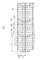
図11は、実施の形態3にかかる受光部の構成例である受光部301の構成を模式的に示すブロック図である。受光部301は、受光部101と同様に、スケール10のパターンを読み取り、読み取り結果を8相正弦波信号として出力する。受光部301は、8つの受光素子311〜318が配置された領域310が2次元的に配置される。
FIG. 11 is a block diagram schematically illustrating a configuration of a
受光素子311〜318の幅は、L/4である。領域310では、受光素子311(α相)、313(β相)、315(α*相)、317(β*相)が列L31に配置される。受光素子312(ξ相)、314(η相)、316(ξ*相)、318(η*相)が列L31に隣接する列L32に配置される。ただし、受光素子312(ξ相)、314(η相)、316(ξ*相)、318(η*相)は、幅方向にL/8だけずらして配置される。
The widths of the
なお、図11では、受光素子に接続される配線については、代表的なもののみを表示し、その他の配線については表示を省略している。 In FIG. 11, only representative wirings connected to the light receiving elements are displayed, and the other wirings are not shown.
以上、本構成によれば、受光素子を2次元的に配置しつつ、エンコーダ100と同様に8相正弦波信号から2相正弦波を生成するエンコーダを実現することができる。
As described above, according to this configuration, it is possible to realize an encoder that generates a two-phase sine wave from an eight-phase sine wave signal, similarly to the
実施の形態4
次に、実施の形態4にかかるエンコーダについて説明する。実施の形態4にかかるエンコーダは、実施の形態2にかかるエンコーダの受光部201を他の構成に変形したものである。以下、受光部の構成に着目して説明する。図12は、実施の形態4にかかる受光部の構成例である受光部401の構成を模式的に示すブロック図である。受光部401は、8つの受光素子411〜418が配置された領域410が2次元的に配置される。
Next, an encoder according to the fourth embodiment will be described. The encoder according to the fourth embodiment is obtained by modifying the
受光素子411〜418の幅は、L/4である。領域410では、受光素子411(α相)、413(β相)、415(α*相)、417(β*相)が列L41に配置される。受光素子412(ξ相)、414(η相)、416(ξ*相)、418(η*相)が列L41に隣接する列L42に配置される。ただし、受光素子412(ξ相)、414(η相)、416(ξ*相)、418(η*相)は、幅方向にL/8だけずらして配置される。つまり、領域410での受光素子の配置は、領域310と同様である。
The width of the
但し、受光素子411(α相)、413(β相)、415(α*相)、417(β*相)の高さh1は、受光素子412(ξ相)、414(η相)、416(ξ*相)、418(η*相)の高さh2h2よりも大きい。具体的には、本実施の形態では、h2/h1=√(√2/2)となっている。 However, the height h1 of the light receiving elements 411 (α phase), 413 (β phase), 415 (α * phase), and 417 (β * phase) is the light receiving elements 412 (ξ phase), 414 (η phase), 416 It is larger than the height h2h2 of (ξ * phase), 418 (η * phase). Specifically, in the present embodiment, h2 / h1 = √ (√2 / 2).
つまり、受光素子412(ξ相)、414(η相)、416(ξ*相)、418(η*相)の面積S2は、受光素子411(α相)、413(β相)、415(α*相)、417(β*相)の面積S1の√2/2倍となる。つまり、受光部401は、受光素子の高さを変えることにより、S2/S1=√2/2とすることができる。これにより、受光素子を2次元的に配置しても、受光部201と同様に、ξ相、η相、ξ*相、η*相の振幅を、α相、β相、α*相、β*相の振幅の√2/2倍とすることができる。
That is, the area S2 of the light receiving elements 412 (ξ phase), 414 (η phase), 416 (ξ * phase), and 418 (η * phase) is equal to the light receiving elements 411 (α phase), 413 (β phase), 415 ( [alpha] * phase) and 417 ([beta] * phase) are 2/2 times the area S1. That is, the
なお、図12では、受光素子に接続される配線については、代表的なもののみを表示し、その他の配線については表示を省略している。 In FIG. 12, only representative wirings connected to the light receiving element are displayed, and the other wirings are not shown.
以上、本構成によれば、受光素子を2次元的に配置しつつ、エンコーダ200と同様に8相正弦波信号から2相正弦波を生成するエンコーダを実現することができる。
As described above, according to this configuration, it is possible to realize an encoder that generates a two-phase sine wave from an eight-phase sine wave signal in the same manner as the
なお、上述の受光部401は例示であり、受光部は別の構成とすることもできる。図13は、受光部401の変形例である受光部401aの構成を示すブロック図である。受光部401aは、8つの受光素子411a〜418aが配置された領域410aが繰り返し配置される。
The
実施の形態1〜3においては、矩形の受光素子を用いたが、受光素子411a(α相)、413a(β相)、415a(α*相)、417a(β*相)は、矩形以外の形状を有する。受光素子411a(α相)、413a(β相)、415a(α*相)、417a(β*相)の高さはh1である。受光素子412a(ξ相)、414a(η相)、416a(ξ*相)、418a(η*相)の高さはh2である。なお、h2/h1=√2/2となっている。また、受光素子411a(α相)、413a(β相)、415a(α*相)、417a(β*相)は屈曲した帯状の形状を有し、帯の幅はL/8である。受光素子412a(ξ相)、414a(η相)、416a(ξ*相)、418a(η*相)は矩形である、その幅はL/4である。これにより、受光素子412a(ξ相)、414a(η相)、416a(ξ*相)、418a(η*相)の面積S2は、受光素子411(α相)、413(β相)、415(α*相)、417(β*相)の面積S1の√2/2倍となる。
In the first to third embodiments, a rectangular light receiving element is used. However, the
受光素子412a(ξ相)は、受光素子411a(α相)及び413a(β相)に取り囲まれて配置される。受光素子414a(η相)は、受光素子413a(β相)及び415a(α*相)に取り囲まれて配置される。受光素子416a(ξ*相)は、受光素子415a(α*相)及び417a(β*相)に取り囲まれて配置される。受光素子418a(η*相)は、受光素子417a(β*相)及び411a(α相)に取り囲まれて配置される。
The
以上、本構成によれば、矩形の受光素子を順に配置しなくとも、受光部401と同様の機能を有する受光部を得ることができる。更に、受光部401aは受光部401と比べて受光素子配置が複雑であるため、受光部上に局所的に汚れなどが付着しても、その影響を低減することが可能である。
As described above, according to this configuration, a light receiving unit having the same function as that of the
また、受光部401aは以下の変形を行うことも可能である。図14は、受光部401aの変形例である受光部401bの構成を示すブロック図である。受光部401bは、8つの受光素子411b〜418bが2組ずつ配置された領域410bが繰り返し配置される。受光素子411b〜418bは、それぞれ受光部401aの受光素子411a〜418aに対応する。受光部401bでは、列L41bにのみ受光素子412b(ξ相)及び416b(ξ*相)を配置し、列L42bにのみ受光素子414b(η相)及び418b(η*相)を配置している。
In addition, the
図15は、受光部401aの別の変形例である受光部401cの構成を示すブロック図である。受光部401cは、8つの受光素子411c〜418cが配置された領域410cが繰り返し配置される。受光素子411c〜418cは、それぞれ受光部401aの受光素子411a〜418aに対応する。受光部401cは、上下方向に隣接する領域410cを上下ミラー反転させた構成を有する。
FIG. 15 is a block diagram illustrating a configuration of a
以上、受光部401b及び401cによっても、ξ相、η相、ξ*相、η*相の振幅を、α相、β相、α*相、β*相の振幅の√2/2倍とすることができる。
As described above, the amplitudes of the ξ phase, η phase, ξ * phase, and η * phase are set to √2 / 2 times the amplitude of the α phase, β phase, α * phase, and β * phase also by the
実施の形態5
次に、実施の形態5にかかるエンコーダについて説明する。実施の形態5では、実施の形態1〜4にかかるエンコーダにおいて、高次高調波の除去態様を詳細に説明する。上述の実施の形態では、N相正弦波が基本波及び3次高調波を含む例(上述の式(3))について説明したが、N相正弦波は任意の次数の高調波を含む形式に一般化することができる。h次(hは、正の整数)までの高調波を含むN相正弦波は、以下の式(20)で表すことができる。なお、Cnはn次の波の振幅、θnはn次の波の初期位相である。
Next, an encoder according to the fifth embodiment will be described. In the fifth embodiment, in the encoders according to the first to fourth embodiments, a high-order harmonic removal mode will be described in detail. In the above-described embodiment, the example in which the N-phase sine wave includes the fundamental wave and the third harmonic (the above formula (3)) has been described. However, the N-phase sine wave has a form including a harmonic of an arbitrary order. It can be generalized. An N-phase sine wave including harmonics up to the h-th order (h is a positive integer) can be expressed by the following equation (20). C n is the amplitude of the n-th wave and θ n is the initial phase of the n-th wave.
このとき、N相正弦波を出力するエンコーダでは、リサージュ曲線zNは複素平面上において、式(4)と同様に、以下の式(21)で表される。
リサージュ曲線zNから導かれるA相及びB相は、式(5)と同様に、以下の式(22)で表される。
上述の定義のもとで、N相正弦波が10次までの高調波を含む場合(h=10)について検討する。まず、5相正弦波(N=5)が10次までの高調波を含む場合について説明する。この場合、式(5)より、A相及びB相は以下の式(23)で表される。
次に、8相正弦波(N=8)が10次までの高調波を含む場合について説明する。この場合、式(5)より、A相及びB相は以下の式(24)で表される。
次に、12相正弦波(N=8)が10次までの高調波を含む場合について説明する。この場合、式(5)より、A相及びB相は以下の式(25)で表される。
以上より、本実施の形態では、h次までの高調波を含むN相正弦波において、(a×N±1)次の高調波以外の高次高調波を除去することが可能である(但し、aは正の整数)。よって、基本波に対してより多くの相を設定すれば除去できる高調波の次数を増やすことができる。また、12相正弦波(N=8)が10次までの高調波を含む場合(h=10、N=12)から理解できるように、除去したい高調波の最高次数(例えば10次)よりも少なくとも2つ多い相(N≧12)を設定することで、全ての高調波を除去することができる。 As described above, in the present embodiment, it is possible to remove high-order harmonics other than the (a × N ± 1) -order harmonics in the N-phase sine wave including the harmonics up to the h-th order (however, , A is a positive integer). Therefore, the number of harmonics that can be removed can be increased by setting more phases with respect to the fundamental wave. Further, as can be understood from the case where the 12-phase sine wave (N = 8) includes harmonics up to the 10th order (h = 10, N = 12), it is higher than the highest order (for example, 10th order) of the harmonics to be removed. By setting at least two more phases (N ≧ 12), all harmonics can be removed.
その他の実施の形態
なお、本発明は上記実施の形態に限られたものではなく、趣旨を逸脱しない範囲で適宜変更することが可能である。例えば、上述の実施の形態では、リニアエンコーダについて説明したが、適宜ロータリエンコーダなどの別の種類のエンコーダとして構成することが可能である。
Other Embodiments The present invention is not limited to the above-described embodiments, and can be appropriately changed without departing from the spirit of the present invention. For example, although the linear encoder has been described in the above-described embodiment, it can be configured as another type of encoder such as a rotary encoder as appropriate.
上述の実施の形態では、光学式のエンコーダについて説明したが、静電式又は電磁誘導方式のエンコーダとして構成することができることは勿論である。 Although the optical encoder has been described in the above-described embodiment, it is needless to say that the encoder can be configured as an electrostatic or electromagnetic induction encoder.
実施の形態4では、受光素子の面積が異なる場合について説明したが、領域に配置される受光素子のそれぞれの面積を同一として、演算部102と組み合わせことも可能である。
In the fourth embodiment, the case where the areas of the light receiving elements are different has been described. However, it is possible to combine the areas of the light receiving elements arranged in the region with the
11〜14 増幅器
21〜24、41、42 減算器
31〜34 加算器
10 スケール
100、200 エンコーダ
101、201、201a、201b、301、401、401a、401b、401c 受光部
102、202 演算部
110、210、210a、210b、310、410、410a、410b、410c 領域
111〜118、211〜218、211a〜218a、211b〜218b、311〜318、411〜418、411a〜418a、411b〜418b、411c〜418c 受光素子
AMP 増幅器
L31、L32、L41、L42 列
R1〜R3 抵抗
11-14 Amplifiers 21-24, 41, 42 Subtractors 31-34
Claims (19)
前記N相正弦波信号のそれぞれに応じてA相及びB相からなる2相正弦波信号を出力する演算部と、を備え、
mを0≦m≦N−1の整数、iを虚数単位、S2πm/Nを前記N相正弦波のm番目の相の正弦波信号として、前記A相及びB相は、以下の式(I)で表され、
前記N相正弦波信号に含まれるn(nは、1≦n≦Nの整数)次の波の振幅をC n 、高次高調波の最大次数をh(hは、正の整数)、前記スケールの繰り返し周期に相当する距離をL、前記n次の波の初期位相をθ n 、ノイズをDとして、
前記N相正弦波のm番目の相の正弦波信号S 2πm/N は、以下の式(II)で表され、
前記式(II)においてN>h+2を満たす、
エンコーダ。
An operation unit that outputs a two-phase sine wave signal composed of an A phase and a B phase according to each of the N-phase sine wave signals,
When m is an integer of 0 ≦ m ≦ N−1, i is an imaginary unit, S 2πm / N is a sine wave signal of the m-th phase of the N-phase sine wave, the A phase and the B phase are expressed by the following formulas ( I) ,
The amplitude of the n-th wave (n is an integer of 1 ≦ n ≦ N) included in the N-phase sine wave signal is C n , the maximum order of the higher harmonics is h (h is a positive integer), The distance corresponding to the repetition period of the scale is L, the initial phase of the n-th wave is θ n , and the noise is D,
The m-th phase sine wave signal S 2πm / N of the N-phase sine wave is represented by the following formula (II):
N> h + 2 is satisfied in the formula (II).
Encoder.
前記第1〜8の正弦波信号は、それぞれm=0〜7の場合に対応する、
請求項1に記載のエンコーダ。 The N-phase sine wave signal is an 8-phase sine wave signal composed of first to eighth sine wave signals,
The first to eighth sine wave signals correspond to the cases where m = 0 to 7, respectively.
The encoder according to claim 1 .
第1の信号から第2の信号を減算した信号を出力する第1の減算器と、
第3の信号から第2の信号を減算した信号を出力する第2の減算器と、
第3の信号から第4の信号を減算した信号を出力する第3の減算器と、
第1の信号から第4の信号を減算した信号を出力する第4の減算器と、
前記第1の正弦波信号と前記第1の減算器の出力信号とを加算する第1の加算器と、
前記第3の正弦波信号と前記第2の減算器の出力信号とを加算する第2の加算器と、
前記第5の正弦波信号と前記第3の減算器の出力信号とを加算する第3の加算器と、
前記第7の正弦波信号と前記第4の減算器の出力信号とを加算する第4の加算器と、
前記第1の加算器の出力信号から前記第3の加算器の出力信号を減算した信号を前記A相として出力する第5の減算器と、
前記第2の加算器の出力信号から前記第4の加算器の出力信号を減算した信号を前記B相として出力する第6の減算器と、を備える、
請求項2に記載のエンコーダ。 The computing unit is
A first subtractor for outputting a signal obtained by subtracting the second signal from the first signal;
A second subtractor for outputting a signal obtained by subtracting the second signal from the third signal;
A third subtractor for outputting a signal obtained by subtracting the fourth signal from the third signal;
A fourth subtractor for outputting a signal obtained by subtracting the fourth signal from the first signal;
A first adder for adding the first sine wave signal and the output signal of the first subtractor;
A second adder for adding the third sine wave signal and the output signal of the second subtractor;
A third adder for adding the fifth sine wave signal and the output signal of the third subtractor;
A fourth adder for adding the seventh sine wave signal and the output signal of the fourth subtractor;
A fifth subtracter that outputs a signal obtained by subtracting the output signal of the third adder from the output signal of the first adder as the A phase;
A sixth subtractor that outputs a signal obtained by subtracting the output signal of the fourth adder from the output signal of the second adder as the B phase;
The encoder according to claim 2 .
前記第1の信号は、前記第2の正弦波信号を√2/2倍した信号であり、
前記第2の信号は、前記第4の正弦波信号を√2/2倍した信号であり、
前記第3の信号は、前記第6の正弦波信号を√2/2倍した信号であり、
前記第4の信号は、前記第8の正弦波信号を√2/2倍した信号である、
請求項3に記載のエンコーダ。 The amplitudes of the first to eighth sine wave signals are the same,
The first signal is a signal obtained by multiplying the second sine wave signal by √2 / 2,
The second signal is a signal obtained by multiplying the fourth sine wave signal by √2 / 2,
The third signal is a signal obtained by multiplying the sixth sine wave signal by √2 / 2,
The fourth signal is a signal obtained by multiplying the eighth sine wave signal by √2 / 2.
The encoder according to claim 3 .
前記第2の正弦波信号を√2/2倍した信号を前記第1の信号として出力する第1の増幅器と、
前記第4の正弦波信号を√2/2倍した信号を前記第2の信号として出力する第2の増幅器と、
前記第6の正弦波信号を√2/2倍した信号を前記第3の信号として出力する第3の増幅器と、
前記第8の正弦波信号を√2/2倍した信号を前記第4の信号として出力する第4の増幅器と、を更に備える、
請求項4に記載のエンコーダ。 The computing unit is
A first amplifier that outputs a signal obtained by multiplying the second sine wave signal by √2 / 2 as the first signal;
A second amplifier that outputs a signal obtained by multiplying the fourth sine wave signal by √2 / 2 as the second signal;
A third amplifier that outputs a signal obtained by multiplying the sixth sine wave signal by √2 / 2 as the third signal;
A fourth amplifier that outputs a signal obtained by multiplying the eighth sine wave signal by √2 / 2 as the fourth signal;
The encoder according to claim 4 .
前記第1の信号は、前記第2の正弦波信号であり、
前記第2の信号は、前記第4の正弦波信号であり、
前記第3の信号は、前記第6の正弦波信号であり、
前記第4の信号は、前記第8の正弦波信号である、
請求項3に記載のエンコーダ。 The amplitude of the second, fourth, sixth and eighth sine wave signals is √2 / 2 times the amplitude of the first, third, fifth and seventh sine wave signals;
The first signal is the second sine wave signal;
The second signal is the fourth sine wave signal;
The third signal is the sixth sine wave signal;
The fourth signal is the eighth sine wave signal.
The encoder according to claim 3 .
前記検知部の移動方向である第1の方向の長さが、前記スケールの1周期の長さと等しい1又は複数の検知領域を備え、
前記検知領域は、
前記スケールからの信号に応じて、それぞれ前記第1〜8の正弦波信号を出力する第1〜8の検知素子を備える、
請求項4又は5に記載のエンコーダ。 The detector is
The length of the first direction which is the moving direction of the detection unit includes one or a plurality of detection areas equal to the length of one cycle of the scale,
The detection area is
In accordance with signals from the scale, the first to eighth detection elements for outputting the first to eighth sine wave signals, respectively, are provided.
The encoder according to claim 4 or 5 .
前記第1〜8の検知素子は、等しい面積を有する、
請求項7に記載のエンコーダ。 The first to eighth sensing elements output the first to eighth sine wave signals having amplitudes corresponding to the areas of the first to eighth sensing elements, respectively.
The first to eighth sensing elements have equal areas.
The encoder according to claim 7 .
請求項8に記載のエンコーダ。 The first to eighth detection elements have the same rectangular shape.
The encoder according to claim 8 .
請求項7乃至9のいずれか一項に記載のエンコーダ。 The first to eighth sensing elements are arranged side by side in the first direction.
The encoder according to any one of claims 7 to 9 .
前記第1、3、5及び7の検知素子が前記第1の方向に並んで配置された第1の列と、
前記第2、4、7及び8の検知素子が前記第1の方向に並んで配置され、前記第1の方向と直交する第2の方向で、前記第1の列と隣接する第2の列と、を備え、
前記第1の列と前記第2の列とは、前記第1〜8の検知素子の前記第1の方向の幅の1/2だけずれて配置される、
請求項10に記載のエンコーダ。 The detection area is
A first row in which the first, third, fifth and seventh sensing elements are arranged side by side in the first direction;
The second row in which the second, fourth, seventh and eighth sensing elements are arranged side by side in the first direction and are adjacent to the first row in a second direction orthogonal to the first direction. And comprising
The first row and the second row are arranged with a shift of ½ of the width in the first direction of the first to eighth sensing elements.
The encoder according to claim 10 .
前記検知部の移動方向である第1の方向の長さが、前記スケールの1周期の長さと等しい1又は複数の検知領域を備え、
前記検知領域は、
前記スケールからの信号に応じて、それぞれ前記第1〜8の正弦波信号を出力する第1〜8の検知素子を備える、
請求項6に記載のエンコーダ。 The detector is
The length of the first direction which is the moving direction of the detection unit includes one or a plurality of detection areas equal to the length of one cycle of the scale,
The detection area is
In accordance with signals from the scale, the first to eighth detection elements for outputting the first to eighth sine wave signals, respectively, are provided.
The encoder according to claim 6 .
前記第2、4、6及び8の検知素子の面積は、前記第1、3、5及び7の検知素子の面積の√2/2倍である、
請求項12に記載のエンコーダ。 The first to eighth sensing elements output the first to eighth sine wave signals having amplitudes corresponding to the areas of the first to eighth sensing elements, respectively.
The area of the second, fourth, sixth and eighth sensing elements is √2 / 2 times the area of the first, third, fifth and seventh sensing elements,
The encoder according to claim 12 .
請求項13に記載のエンコーダ。 The first to eighth sensing elements are arranged side by side in the first direction.
The encoder according to claim 13 .
前記第1〜8の検知素子の前記第1の方向と直行する第2の方向の高さは等しい、
請求項14に記載のエンコーダ。 The width in the first direction of the second, fourth, sixth and eighth sensing elements is √2 / 2 times the width in the first direction of the first, third, fifth and seventh sensing elements. ,
The heights of the first direction of the first to eighth detection elements in the second direction perpendicular to the first direction are equal,
The encoder according to claim 14 .
前記第1〜8の検知素子の前記第1の方向の幅は等しい、
請求項14に記載のエンコーダ。 The heights of the second direction orthogonal to the first direction of the second, fourth, sixth and eighth sensing elements are the heights of the second direction of the first, third, fifth and seventh sensing elements. √2 / 2 times that,
The first to eighth sensing elements have equal widths in the first direction;
The encoder according to claim 14 .
前記第1、3、5及び7の検知素子が前記第1の方向に並んで配置された第1の列と、
前記第2、4、7及び8の検知素子が前記第1の方向に並んで配置され、前記第2の方向で、前記第1の列と隣接する第2の列と、を備え、
前記第1の列と前記第2の列とは、前記第1〜8の検知素子の前記第1の方向の幅の1/2だけずれて配置される、
請求項16に記載のエンコーダ。 The detection area is
A first row in which the first, third, fifth and seventh sensing elements are arranged side by side in the first direction;
The second, fourth, seventh, and eighth sensing elements are arranged side by side in the first direction, and the second row is adjacent to the first row in the second direction, and
The first row and the second row are arranged with a shift of ½ of the width in the first direction of the first to eighth sensing elements.
The encoder according to claim 16 .
請求項7乃至17のいずれか一項に記載のエンコーダ。 Each of the first to eighth detection elements is a light receiving element that outputs a signal obtained by photoelectrically converting light reflected by the scale as the first to eighth sine wave signals.
The encoder according to any one of claims 7 to 17 .
請求項7乃至17のいずれか一項に記載のエンコーダ。 The first to eighth sensing elements output the first to eighth sine wave signals by a capacitance method or an electromagnetic induction method, respectively.
The encoder according to any one of claims 7 to 17 .
Priority Applications (4)
| Application Number | Priority Date | Filing Date | Title |
|---|---|---|---|
| JP2012159302A JP5964162B2 (en) | 2012-07-18 | 2012-07-18 | Encoder |
| US13/944,162 US9329056B2 (en) | 2012-07-18 | 2013-07-17 | Encoder including detector for reading signal and outputting N-phase sinusoidal signals and computing part for outputting two-phase sinusoidal signal |
| CN201310303668.9A CN103575301B (en) | 2012-07-18 | 2013-07-18 | Encoder |
| EP13177086.9A EP2687821B1 (en) | 2012-07-18 | 2013-07-18 | Encoder |
Applications Claiming Priority (1)
| Application Number | Priority Date | Filing Date | Title |
|---|---|---|---|
| JP2012159302A JP5964162B2 (en) | 2012-07-18 | 2012-07-18 | Encoder |
Publications (2)
| Publication Number | Publication Date |
|---|---|
| JP2014020896A JP2014020896A (en) | 2014-02-03 |
| JP5964162B2 true JP5964162B2 (en) | 2016-08-03 |
Family
ID=48793979
Family Applications (1)
| Application Number | Title | Priority Date | Filing Date |
|---|---|---|---|
| JP2012159302A Active JP5964162B2 (en) | 2012-07-18 | 2012-07-18 | Encoder |
Country Status (4)
| Country | Link |
|---|---|
| US (1) | US9329056B2 (en) |
| EP (1) | EP2687821B1 (en) |
| JP (1) | JP5964162B2 (en) |
| CN (1) | CN103575301B (en) |
Families Citing this family (1)
| Publication number | Priority date | Publication date | Assignee | Title |
|---|---|---|---|---|
| KR20220120335A (en) | 2021-02-23 | 2022-08-30 | 주식회사 엘지에너지솔루션 | Battery pack comprising PCM having direct junction structure with battery cell |
Family Cites Families (13)
| Publication number | Priority date | Publication date | Assignee | Title |
|---|---|---|---|---|
| DE3239108A1 (en) * | 1982-10-22 | 1984-04-26 | Dr. Johannes Heidenhain Gmbh, 8225 Traunreut | POSITION MEASUREMENT METHOD AND DEVICES FOR CARRYING OUT THE METHOD |
| DE3616144A1 (en) | 1986-05-14 | 1987-11-19 | Heidenhain Gmbh Dr Johannes | PHOTOELECTRICAL MEASURING DEVICE |
| JP2539269B2 (en) * | 1989-07-17 | 1996-10-02 | オークマ株式会社 | Optical encoder |
| JP2695623B2 (en) * | 1994-11-25 | 1998-01-14 | 株式会社ミツトヨ | Optical encoder |
| US6029363A (en) * | 1998-04-03 | 2000-02-29 | Mitutoyo Corporation | Self-calibrating position transducer system and method |
| JP2005524050A (en) * | 2001-08-30 | 2005-08-11 | マイクロイー システムズ コーポレイション | Harmonic suppression photodetector array |
| JP4713123B2 (en) * | 2004-10-13 | 2011-06-29 | 株式会社ミツトヨ | Encoder output signal correction device |
| JP2007248302A (en) | 2006-03-16 | 2007-09-27 | Mitsutoyo Corp | Photoelectric incremental type encoder |
| JP5113000B2 (en) * | 2008-09-19 | 2013-01-09 | 株式会社ミツトヨ | Photoelectric encoder |
| GB0903550D0 (en) | 2009-03-02 | 2009-04-08 | Rls Merilna Tehnika D O O | Position encoder apparatus |
| JP2010216961A (en) | 2009-03-16 | 2010-09-30 | Mitsutoyo Corp | Encoder output signal correction apparatus and method |
| JP5641746B2 (en) * | 2010-02-12 | 2014-12-17 | 株式会社ミツトヨ | Photoelectric encoder |
| JP5562077B2 (en) * | 2010-03-10 | 2014-07-30 | キヤノン株式会社 | Optical encoder, encoder, interference measurement device, measurement method |
-
2012
- 2012-07-18 JP JP2012159302A patent/JP5964162B2/en active Active
-
2013
- 2013-07-17 US US13/944,162 patent/US9329056B2/en active Active
- 2013-07-18 CN CN201310303668.9A patent/CN103575301B/en active Active
- 2013-07-18 EP EP13177086.9A patent/EP2687821B1/en active Active
Also Published As
| Publication number | Publication date |
|---|---|
| CN103575301B (en) | 2017-07-18 |
| JP2014020896A (en) | 2014-02-03 |
| EP2687821A1 (en) | 2014-01-22 |
| US20140021342A1 (en) | 2014-01-23 |
| CN103575301A (en) | 2014-02-12 |
| US9329056B2 (en) | 2016-05-03 |
| EP2687821B1 (en) | 2018-07-11 |
Similar Documents
| Publication | Publication Date | Title |
|---|---|---|
| EP2085751A1 (en) | Electromagnetic Induction Type Encoder | |
| JP5641746B2 (en) | Photoelectric encoder | |
| US8173951B2 (en) | Optical encoder comprising a main and reference light receiving portions with a three-phase signal generation for detecting displacement and direction of displacement of an incremental grating track | |
| JP5616741B2 (en) | Encoder | |
| EP2369303B1 (en) | Optical encoder | |
| JP6032924B2 (en) | Encoder | |
| JP5761181B2 (en) | Position detection device | |
| JP5964162B2 (en) | Encoder | |
| JPH07229757A (en) | Signal processing device, position detecting device and driving device | |
| EP2369304A1 (en) | Photoelectric encoder | |
| JP2008083019A (en) | Photoelectric encoder and electronic device using the same | |
| JPH08285637A (en) | Scale and encoder | |
| JP3327718B2 (en) | Optical encoder | |
| EP2587226B1 (en) | Displacement detecting device and method | |
| JP3245610B2 (en) | Device for filtering odd-order harmonic signal components | |
| JP2004309366A (en) | Position detecting device | |
| JP6517540B2 (en) | Phase adjuster and encoder | |
| US10094685B2 (en) | Displacement encoder | |
| JP2015087247A (en) | Optical encoder | |
| EP2778626B1 (en) | Position detection apparatus, lens apparatus, image pickup system, machine tool apparatus, position detection method, program, and storage medium | |
| JP5927482B2 (en) | Optical encoder device | |
| JPH0658769A (en) | Signal processing method and displacement detector using method thereof | |
| JP6196539B2 (en) | Optical encoder | |
| KR20210046463A (en) | Linear encorder apparatus | |
| JP2015105854A (en) | Optical absolute encoder |
Legal Events
| Date | Code | Title | Description |
|---|---|---|---|
| A621 | Written request for application examination |
Free format text: JAPANESE INTERMEDIATE CODE: A621 Effective date: 20150604 |
|
| A977 | Report on retrieval |
Free format text: JAPANESE INTERMEDIATE CODE: A971007 Effective date: 20160421 |
|
| A131 | Notification of reasons for refusal |
Free format text: JAPANESE INTERMEDIATE CODE: A131 Effective date: 20160426 |
|
| A521 | Request for written amendment filed |
Free format text: JAPANESE INTERMEDIATE CODE: A523 Effective date: 20160531 |
|
| TRDD | Decision of grant or rejection written | ||
| A01 | Written decision to grant a patent or to grant a registration (utility model) |
Free format text: JAPANESE INTERMEDIATE CODE: A01 Effective date: 20160621 |
|
| A61 | First payment of annual fees (during grant procedure) |
Free format text: JAPANESE INTERMEDIATE CODE: A61 Effective date: 20160629 |
|
| R150 | Certificate of patent or registration of utility model |
Ref document number: 5964162 Country of ref document: JP Free format text: JAPANESE INTERMEDIATE CODE: R150 |
|
| R250 | Receipt of annual fees |
Free format text: JAPANESE INTERMEDIATE CODE: R250 |
|
| R250 | Receipt of annual fees |
Free format text: JAPANESE INTERMEDIATE CODE: R250 |