JP5963455B2 - Irradiation apparatus and image reading apparatus - Google Patents
Irradiation apparatus and image reading apparatus Download PDFInfo
- Publication number
- JP5963455B2 JP5963455B2 JP2012016130A JP2012016130A JP5963455B2 JP 5963455 B2 JP5963455 B2 JP 5963455B2 JP 2012016130 A JP2012016130 A JP 2012016130A JP 2012016130 A JP2012016130 A JP 2012016130A JP 5963455 B2 JP5963455 B2 JP 5963455B2
- Authority
- JP
- Japan
- Prior art keywords
- light
- light guide
- reflection
- longitudinal direction
- diffuse reflection
- Prior art date
- Legal status (The legal status is an assumption and is not a legal conclusion. Google has not performed a legal analysis and makes no representation as to the accuracy of the status listed.)
- Active
Links
Images


Classifications
-
- G—PHYSICS
- G02—OPTICS
- G02B—OPTICAL ELEMENTS, SYSTEMS OR APPARATUS
- G02B6/00—Light guides; Structural details of arrangements comprising light guides and other optical elements, e.g. couplings
- G02B6/0001—Light guides; Structural details of arrangements comprising light guides and other optical elements, e.g. couplings specially adapted for lighting devices or systems
- G02B6/0096—Light guides; Structural details of arrangements comprising light guides and other optical elements, e.g. couplings specially adapted for lighting devices or systems the lights guides being of the hollow type
-
- G—PHYSICS
- G02—OPTICS
- G02B—OPTICAL ELEMENTS, SYSTEMS OR APPARATUS
- G02B5/00—Optical elements other than lenses
- G02B5/02—Diffusing elements; Afocal elements
- G02B5/0205—Diffusing elements; Afocal elements characterised by the diffusing properties
- G02B5/021—Diffusing elements; Afocal elements characterised by the diffusing properties the diffusion taking place at the element's surface, e.g. by means of surface roughening or microprismatic structures
- G02B5/0231—Diffusing elements; Afocal elements characterised by the diffusing properties the diffusion taking place at the element's surface, e.g. by means of surface roughening or microprismatic structures the surface having microprismatic or micropyramidal shape
-
- G—PHYSICS
- G02—OPTICS
- G02B—OPTICAL ELEMENTS, SYSTEMS OR APPARATUS
- G02B5/00—Optical elements other than lenses
- G02B5/02—Diffusing elements; Afocal elements
- G02B5/0273—Diffusing elements; Afocal elements characterized by the use
- G02B5/0284—Diffusing elements; Afocal elements characterized by the use used in reflection
-
- G—PHYSICS
- G02—OPTICS
- G02B—OPTICAL ELEMENTS, SYSTEMS OR APPARATUS
- G02B6/00—Light guides; Structural details of arrangements comprising light guides and other optical elements, e.g. couplings
- G02B6/0001—Light guides; Structural details of arrangements comprising light guides and other optical elements, e.g. couplings specially adapted for lighting devices or systems
- G02B6/0005—Light guides; Structural details of arrangements comprising light guides and other optical elements, e.g. couplings specially adapted for lighting devices or systems the light guides being of the fibre type
- G02B6/001—Light guides; Structural details of arrangements comprising light guides and other optical elements, e.g. couplings specially adapted for lighting devices or systems the light guides being of the fibre type the light being emitted along at least a portion of the lateral surface of the fibre
-
- G—PHYSICS
- G02—OPTICS
- G02B—OPTICAL ELEMENTS, SYSTEMS OR APPARATUS
- G02B6/00—Light guides; Structural details of arrangements comprising light guides and other optical elements, e.g. couplings
- G02B6/24—Coupling light guides
- G02B6/42—Coupling light guides with opto-electronic elements
- G02B6/4201—Packages, e.g. shape, construction, internal or external details
- G02B6/4204—Packages, e.g. shape, construction, internal or external details the coupling comprising intermediate optical elements, e.g. lenses, holograms
-
- G—PHYSICS
- G02—OPTICS
- G02B—OPTICAL ELEMENTS, SYSTEMS OR APPARATUS
- G02B6/00—Light guides; Structural details of arrangements comprising light guides and other optical elements, e.g. couplings
- G02B6/24—Coupling light guides
- G02B6/42—Coupling light guides with opto-electronic elements
- G02B6/4298—Coupling light guides with opto-electronic elements coupling with non-coherent light sources and/or radiation detectors, e.g. lamps, incandescent bulbs, scintillation chambers
-
- H—ELECTRICITY
- H04—ELECTRIC COMMUNICATION TECHNIQUE
- H04N—PICTORIAL COMMUNICATION, e.g. TELEVISION
- H04N1/00—Scanning, transmission or reproduction of documents or the like, e.g. facsimile transmission; Details thereof
- H04N1/024—Details of scanning heads ; Means for illuminating the original
- H04N1/028—Details of scanning heads ; Means for illuminating the original for picture information pick-up
- H04N1/02815—Means for illuminating the original, not specific to a particular type of pick-up head
- H04N1/0282—Using a single or a few point light sources, e.g. a laser diode
- H04N1/02825—Using a single or a few point light sources, e.g. a laser diode in combination with at least one reflector which is fixed in relation to the light source
-
- H—ELECTRICITY
- H04—ELECTRIC COMMUNICATION TECHNIQUE
- H04N—PICTORIAL COMMUNICATION, e.g. TELEVISION
- H04N1/00—Scanning, transmission or reproduction of documents or the like, e.g. facsimile transmission; Details thereof
- H04N1/024—Details of scanning heads ; Means for illuminating the original
- H04N1/028—Details of scanning heads ; Means for illuminating the original for picture information pick-up
- H04N1/02815—Means for illuminating the original, not specific to a particular type of pick-up head
- H04N1/0282—Using a single or a few point light sources, e.g. a laser diode
- H04N1/02835—Using a single or a few point light sources, e.g. a laser diode in combination with a light guide, e.g. optical fibre, glass plate
-
- H—ELECTRICITY
- H04—ELECTRIC COMMUNICATION TECHNIQUE
- H04N—PICTORIAL COMMUNICATION, e.g. TELEVISION
- H04N1/00—Scanning, transmission or reproduction of documents or the like, e.g. facsimile transmission; Details thereof
- H04N1/024—Details of scanning heads ; Means for illuminating the original
- H04N1/028—Details of scanning heads ; Means for illuminating the original for picture information pick-up
- H04N1/02815—Means for illuminating the original, not specific to a particular type of pick-up head
- H04N1/02885—Means for compensating spatially uneven illumination, e.g. an aperture arrangement
- H04N1/0289—Light diffusing elements, e.g. plates or filters
-
- F—MECHANICAL ENGINEERING; LIGHTING; HEATING; WEAPONS; BLASTING
- F21—LIGHTING
- F21Y—INDEXING SCHEME ASSOCIATED WITH SUBCLASSES F21K, F21L, F21S and F21V, RELATING TO THE FORM OR THE KIND OF THE LIGHT SOURCES OR OF THE COLOUR OF THE LIGHT EMITTED
- F21Y2115/00—Light-generating elements of semiconductor light sources
- F21Y2115/10—Light-emitting diodes [LED]
-
- G—PHYSICS
- G02—OPTICS
- G02B—OPTICAL ELEMENTS, SYSTEMS OR APPARATUS
- G02B6/00—Light guides; Structural details of arrangements comprising light guides and other optical elements, e.g. couplings
- G02B6/0001—Light guides; Structural details of arrangements comprising light guides and other optical elements, e.g. couplings specially adapted for lighting devices or systems
- G02B6/0011—Light guides; Structural details of arrangements comprising light guides and other optical elements, e.g. couplings specially adapted for lighting devices or systems the light guides being planar or of plate-like form
- G02B6/0081—Mechanical or electrical aspects of the light guide and light source in the lighting device peculiar to the adaptation to planar light guides, e.g. concerning packaging
- G02B6/0085—Means for removing heat created by the light source from the package
Description
本発明は、照射装置及び画像読取装置に関する。 The present invention relates to an irradiation apparatus and an image reading apparatus.
画像読取装置は、照射装置が原稿に光を照射し、その照射光が原稿で反射した光を受けて原稿に表された情報を含む画像データを生成する。照射光の光源には、キセノンランプやハロゲンランプが多く用いられてきたが、近年では省電力化の流れに沿って、発光ダイオード(LED;Light Emitting Diode)へ置き換えられつつある(例えば、特許文献1,2参照)。 In the image reading apparatus, the irradiating device irradiates light on the original, and the irradiation light receives light reflected by the original to generate image data including information represented on the original. Xenon lamps and halogen lamps have often been used as the light source of irradiation light, but in recent years, light emitting diodes (LEDs) are being replaced in accordance with the trend of power saving (for example, patent documents). 1 and 2).
一般に原稿の折り目やしわ、書籍を原稿とする場合のページの開き目の近傍などは、画像読取装置により生成された画像データが示す画像において影になって表れることがある。特許文献1に記載されたイメージセンサや、特許文献2に記載された2分岐線状光源装置は、このような影の発生を抑えるために、複数の方向から原稿に照明光を照射する。
In general, the folds and wrinkles of a document, the vicinity of a page opening when a book is a document, and the like may appear as shadows in an image indicated by image data generated by the image reading apparatus. The image sensor described in
特許文献1に記載のイメージセンサは、端部に配置されたLEDからの光を伝搬する棒状の導光体を備える。導光体は、伝搬する光を散乱反射する第1及び第2光散乱層と、第1光散乱層で散乱反射された光を出射させる第1出射部と、第2光散乱層で散乱反射された光を出射させる第2出射部とを有する。第1出射部から出射された光(主光)は、原稿の照射部を斜め方向から直接照射する。第2出射部から出射された光(副光)は、反射体で反射されて、原稿の照射部に対して斜め方向から照射する。副光は、原稿の照射部から反射された光を収束するレンズ体に対して主光とは反対側から原稿の照射部を照射する。
The image sensor described in
特許文献1に記載のイメージセンサでは、主光と副光との光量のバランスをとることで折り目やしわにより影が生じることを少なくするため、第2光散乱層は第1光散乱層よりも幅広とされる。
In the image sensor described in
特許文献2に記載の2分岐線状光源装置では、導光体の長手方向から見た反射鏡(反射体)の断面形状が楕円状や放物線状に形成される。これによって、反射鏡で反射して原稿読取面を照射する光(副光)の広がり幅が直接原稿読取面を照射する光(主光)のそれと同程度となる。 In the two-branch linear light source device described in Patent Document 2, the cross-sectional shape of the reflector (reflector) viewed from the longitudinal direction of the light guide is formed in an elliptical shape or a parabolic shape. As a result, the spread width of the light (sub-light) that is reflected by the reflecting mirror and irradiates the original reading surface becomes approximately the same as that of the light (main light) that directly irradiates the original reading surface.
しかしながら、特許文献1に記載のイメージセンサでは、原稿の照射部における原稿搬送方向の主光と副光とのそれぞれの広がり幅が異なり、主光と副光とはいずれも原稿の照射部に対して斜め方向から照射する。このような場合、原稿が上述のレンズ体の光軸方向へイメージセンサからの距離が変化すると、その距離に応じて原稿の照射部における照度が変化することがある。そのため、書籍のページの開き目の近傍などで原稿をイメージセンサから所定の距離で配置できない部分は、生成された画像データが示す画像において濃淡が変化することがある。
However, in the image sensor described in
引用文献2に記載の2分岐線状光源装置では、楕円状や放物線状の断面形状を有する反射鏡が採用される。このような反射鏡は2分岐線状光源装置において高精度で位置決めされる必要があり、2分岐線状光源装置を組み立てることは容易ではない。 In the two-branch linear light source device described in the cited document 2, a reflecting mirror having an elliptical or parabolic cross-sectional shape is employed. Such a reflecting mirror needs to be positioned with high accuracy in the two-branch linear light source device, and it is not easy to assemble the two-branch linear light source device.
本発明は、上述の事情を鑑みてなされたもので、照明深度を深くし、かつ、容易に組み立てることが可能な照射装置などを提供することを目的とする。 The present invention has been made in view of the above-described circumstances, and an object thereof is to provide an irradiation apparatus that can be easily assembled with a deep illumination depth.
上記目的を達成するため、本発明に係る照射装置は、
光を発する光源部と、
断面の概形となる円の半径がRであって、前記光源部が端部近傍に配置される透明な棒状の導光体と、
前記導光体の長手方向に延びて設けられており、前記導光体の内部を伝搬する光を拡散して反射させる第1の拡散反射部と、
前記第1の拡散反射部の反射方向にある前記導光体の外面で前記長手方向に延びる部分であって、前記第1の拡散反射部により反射された光を主光として出射させる第1の出射部と、
前記導光体の前記長手方向に延びて設けられており、前記導光体の内部を伝搬する光を拡散して反射させる第2の拡散反射部と、
前記第2の拡散反射部の反射方向にある前記導光体の外面で前記長手方向に延びる部分であって、前記第2の拡散反射部により反射された光を副光として出射させる第2の出射部と、
所定の領域において前記主光と重なり合う方向へ前記副光を反射する平面鏡とを備え、
前記第2の出射部は、前記長手方向から見た形状が1/Rの曲率の曲線であり、
前記第1の出射部は、平面又は前記長手方向から見て前記第2の出射部の曲率である1/Rの曲率より小さい曲率で定義された凸形状の曲面であり、
前記主光は前記副光よりも広い発散角を有する。
In order to achieve the above object, an irradiation apparatus according to the present invention includes:
A light source that emits light;
A transparent rod-shaped light guide body in which the radius of a circle that is an outline of a cross section is R, and the light source part is disposed in the vicinity of the end part;
A first diffusive reflection part that extends in the longitudinal direction of the light guide and diffuses and reflects light propagating through the light guide;
A portion extending in the longitudinal direction on the outer surface of the light guide in the reflection direction of the first diffuse reflection portion, wherein the light reflected by the first diffuse reflection portion is emitted as main light. An emission part;
A second diffusive reflecting portion that extends in the longitudinal direction of the light guide and diffuses and reflects light propagating through the light guide;
A portion extending in the longitudinal direction on the outer surface of the light guide in the reflection direction of the second diffuse reflection portion, wherein the light reflected by the second diffuse reflection portion is emitted as secondary light. An emission part;
A plane mirror that reflects the sub-light in a direction overlapping the main light in a predetermined region;
The second emission part is a curve having a curvature of 1 / R as viewed from the longitudinal direction,
The first emission part is a convex curved surface defined with a curvature smaller than a curvature of 1 / R which is a curvature of the second emission part as seen from a plane or the longitudinal direction,
The main light has a wider divergence angle than the sub-light.
本発明によれば、第1の出射部が第2の出射部より小さい曲率の曲面又は平面を有するため、主光は副光よりも広い発散角を有する。これによって、照明深度を深くすることが可能になる。また、副光を反射する鏡は平面鏡であるため、容易に組み立てることが可能になる。 According to the present invention, the main light has a wider divergence angle than the sub-light because the first emission part has a curved surface or plane having a smaller curvature than the second emission part. This makes it possible to increase the illumination depth. Further, since the mirror that reflects the auxiliary light is a plane mirror, it can be easily assembled.
以下、本発明の実施の形態について、図面を参照しつつ説明する。全図を通じて同一の要素には同一の符号を付す。また、同一の要素に関して重複する説明は省略する。なお、画像読取装置を構成する部材の寸法比は適宜変更されてよく、各図に示すものに限られない。 Embodiments of the present invention will be described below with reference to the drawings. The same elements are denoted by the same reference symbols throughout the drawings. In addition, overlapping description of the same elements is omitted. Note that the dimensional ratio of members constituting the image reading apparatus may be changed as appropriate, and is not limited to those shown in the drawings.
実施の形態1.
本発明の実施の形態1に係る画像読取装置100は、図1にその分解斜視図を示すように、コンタクトガラス103に載置された原稿104原稿の一面(読取面)に表された文字、図形、記号などの情報を読み取り、読み取った情報を含む画像データを出力する装置である。なお、原稿104は画像読取装置100に情報を読み取らせる対象となる物の一例である。
As shown in an exploded perspective view of FIG. 1, the
画像読取装置100は、同図に示すように、照射装置101と読取装置102とを備える。
As shown in FIG. 1, the
照射装置101は、ライン状の読取領域105に2方向から光を照射する装置である。なお、読取領域105は、照射装置101を用いて最適な照度及び照度分布で光を照射することができる領域として適宜定められてよい。
The
照射装置101は、同図に示すように、導光体110と第1のリフレクタ111と第2のリフレクタ112と2つの光源部113と2つのホルダ114と平面鏡115とを備える。
The
導光体110は、例えばアクリルやシクロオレフィン系の透明樹脂、ガラスなどの材料で作られた透明な棒状の部材である。導光体110の長手方向は照射装置101の長手方向(以下、「Y方向」という。)を規定する。導光体110をY方向から見た断面(以下、「導光体110の断面」という。)は概ね円形であり、詳細には例えば、照射装置101をY方向から見た断面図である図2に示すように円形の一部を切り欠いた形状をなす。
The
導光体110は、例えば図2に示すように、その外面に、第1のプリズム群121と第1の出射部122と第2のプリズム群123と第2の出射部124とを備える。
For example, as illustrated in FIG. 2, the
第1のプリズム群121は多数の微小なプリズムを備え、導光体110のY方向に延びる外面(外側面)を形成する。
The
図3は、図2のI−I線での、すなわち第1のプリズム群121のY方向に垂直な幅方向の中心と導光体110の中心軸(以下、単に「軸」という。)126とを含む平面での断面を矢示方向から見た断面図を示す。図3の破線丸囲みの領域128を拡大して図4に示すように、第1のプリズム群121の各プリズム132は例えば、Y方向に帯状に延びる平面をなす領域(第1のプリズム領域)131から導光体110の断面の径方向に突き出す山型をなし、不均一なピッチで千数百〜数千本Y方向に並ぶ。第1のプリズム群121の各プリズム132の幅は例えば約100μmである。
FIG. 3 is a cross-sectional view taken along line II in FIG. 2, that is, the center in the width direction perpendicular to the Y direction of the
第1のプリズム群121の各プリズム132の稜線134は例えば、Y方向に垂直な面と平行に設けられており、第1のプリズム領域131と平行である。
For example, the
第1の出射部122は、図2及び図3に示すように、導光体110の外面のY方向に帯状に延びる部分であって、導光体110の軸126を挟んで概ね第1のプリズム群121に対向する位置に設けられる。第1の出射部122は、導光体110の軸126に平行な平面を形成する平面部136を有する。第1の出射部122は、さらに、図2に示すように長手方向から見た場合に、平面部136の両端に接続する導光体110の概形をなす円周の一部(円周部)137を含む。
As shown in FIG. 2 and FIG. 3, the first emitting
なお、第1の出射部122は、平面部136に代えて、導光体110の断面の概形となる円の半径をR[m]とした場合に、曲率が1/Rよりも小さい曲面を形成する曲面部を備えてもよい。また、第1の出射部122は円周部137を含まなくてもよい。
The first emitting
第2のプリズム群123は多数の微小なプリズムを備え、導光体110の外側面を形成する。図1に示すように、第2のプリズム群123は、導光体110の外側面において第1のプリズム群121と第1の出射部122との間に設けられる。詳細には例えば、第2のプリズム群123は、図2に示すようにY方向から見た場合に、導光体110の外側面の概形をなす円を第1のプリズム群121と第1の出射部122との中間を通る直径で分けた2つの半円のうち、第1のプリズム群121が設けられている側の半円内に設けられる。
The
図5は、図2のII−II線での、すなわち第2のプリズム群123のY方向に垂直な幅方向の中心と導光体110の軸126とを含む平面での断面を矢示方向から見た断面図を示す。第2のプリズム群123は例えば、第1のプリズム群121と同様に、Y方向に帯状に延びる平面をなす領域(第2のプリズム領域)から導光体110の断面の径方向に突き出す山型をなし、不均一なピッチで千数百〜数千本Y方向に並ぶ(図4参照)。第2のプリズム群123の各プリズム132の幅は例えば約100μmである。
5 is a cross-sectional view taken along a line II-II in FIG. 2, that is, a plane including a center in the width direction perpendicular to the Y direction of the
第2のプリズム群123の各プリズム132の稜線134は例えば、第1のプリズム群121を構成するものと同様に、Y方向に垂直な面と平行に設けられており、第2のプリズム領域と平行である。
The
第2の出射部124は、図2及び図5に示すように、導光体110の外面でY方向に帯状に延びる部分であって、導光体110の軸126を挟んで概ね第2のプリズム群123に対向する位置に形成される。第2の出射部124は、長手方向から見た場合に、導光体110の概形を形成する円の一部をなす。すなわち、導光体110の断面の概形となる円の半径をR[m]とした場合、第2の出射部124の曲率は1/Rである。
As shown in FIGS. 2 and 5, the second emitting
第1のリフレクタ111は、図1に示すようにY方向に延びる帯状の部材であって、例えば白色のポリカーボネート等の樹脂で作られる。
The
第1のリフレクタ111は、その一面に光を反射する面(第1の反射面)141を有する。第1の反射面141は、原稿104の読取面での照度を向上させるために、例えば90%以上の高い反射率であることが望ましく、そのため梨地面(ざらつきのある面)又は鏡面である。なお、第1のリフレクタ111は例えば金属板金のような構造部材に白色テープを貼ったものであってもよい。
The
第1の反射面141は、第1のリフレクタ111の形状に応じてY方向に延びる帯状をなしており、図2及び図3に示すように第1のプリズム群121に所定の距離だけ離間して対置される。第1の反射面141は第1のプリズム群121より広く、第1のプリズム群121の全体を覆うように配置される。本実施の形態では、第1のプリズム群121と第1のリフレクタ(反射部)111とにより第1の拡散反射部が構成される。
The first reflecting
第2のリフレクタ112は、図1に示すようにY方向に延びる帯状の部材であって、例えば白色のポリカーボネート等の樹脂で作られる。
The
第2のリフレクタ112は、その一面に光を反射する梨地面又は鏡面(第2の反射面)143を有する。第2の反射面143は、原稿104の読取面での照度を向上させるために、例えば90%以上の高い反射率であることが望ましく、そのため梨地面又は鏡面である。なお、第2のリフレクタ112は例えば金属板金のような構造部材に白色テープを貼ったものであってもよい。
The
第2の反射面143は、第2のリフレクタ112の形状に応じてY方向に延びる帯状をなしており、図2及び図5に示すように第2のプリズム群123に所定の距離だけ離間して対置される。第2の反射面143は第2のプリズム群123より広く、第2のプリズム群123の全体を覆うように配置される。本実施の形態では、第2のプリズム群123と第2のリフレクタ(反射部)112とにより第2の拡散反射部が構成される。
The second reflecting
各光源部113は、例えば図1に示すように、光源であるLED(Light Emitting Diode)151と、一方の面にLED151が設けられた基板152とを備える。基板152はアルミニウム等の金属、ガラスエポキシ、ポリイミド等の樹脂、セラミック等を材料として作られている。基板152は、コネクタを介して電源ケーブルが接続されており(図示せず)、それによって、LED151を点灯されるための電力が供給される。
For example, as shown in FIG. 1, each
各ホルダ114は、例えば図1に示すように、導光体110と光源部113とを保持する部材である。各ホルダ114は、光源部113を取り付ける光源取付部161と、導光体110の端部が嵌合する嵌合部162とを備える。光源取付部161に光源部113が取り付けられると、LED151はホルダ114内の光源空間165に配置される(図3,図5参照)。
Each
嵌合部162は、Y方向から見た場合に、導光体110の断面の概形をなす円より僅かに大きいか、それと同程度の大きさの概ね円形をなす孔を形成する。嵌合部162が形成する孔は光源空間165と連通する。なお、第1の出射部122の平面部136又は曲面部が導光体110の端面168まで延びて設けられる場合には、嵌合部162は、導光体110の端部が嵌合した場合に第1の出射部122が当接する当接部(第1の当接部)を有する。
When viewed from the Y direction, the
このような構成を備えることによって、光源部113と導光体110とがホルダ114に保持された場合、LED151と導光体110の端面168とは対置され、導光体110の端部はホルダ114で覆われる。この場合、LED151と導光体110の端面168とは近接していることが望ましい。
With this configuration, when the
各ホルダ114は、例えばLED151が発する光を拡散反射するために、白色のポリカーボネート等の樹脂から成り、光源空間165を形成する面及び嵌合部162の孔を形成する面は、原稿104の読取面での照度を向上させるために高い反射率を有することが望ましく、例えば梨地面又は鏡面である。
Each
各ホルダ114には、例えば図1に示すように、LED151が発光している間の温度上昇を抑えるために、光源部113の背面、すなわち基板152のLED151が設けられていない方の面にヒートシンク169が設けられる。
For example, as shown in FIG. 1, each
平面鏡115は、図1に示すように、Y方向に帯状に延びる平らな鏡面を有する。平面鏡115は例えば、研磨されたガラス基材の一面にアルミニウム等の金属を蒸着して平らな鏡面を形成すること、アルミニウム等の金属製の部材の一面を研磨して平らな鏡面を形成することなどによって製造される。平面鏡115の鏡面は原稿104の読取面での照度を向上させるために高い反射率であることが望ましく、そのため例えば増反射コートが施されていてもよい。
As shown in FIG. 1, the
平面鏡115は、図2に示すように、第2のプリズム群123から第2の出射部124を臨む方向に配置される。なお、照射装置101の短手方向(以下、「X方向」という。)は、Y方向から見て、導光体110の軸126と平面鏡115の鏡面上の点(典型的には、平面鏡115の鏡面の中心)170とを結ぶ線の方向により規定される。
As shown in FIG. 2, the
平面鏡115の鏡面は第2の出射部124の方向を向き、望ましくは副光Lsが通過する全域に広がり、これによって、第2の出射部124から出射される副光Lsのほぼ全体を反射する。平面鏡115の鏡面は、反射した副光Lsと第1の出射部122から出射される主光Lmとが重なり合う方向を向けて配置される。主光Lmと副光Lsとが重なり合う領域が読取領域105となる。
The mirror surface of the
読取領域105は、導光体110の軸126と平面鏡115の鏡面上のY方向に延びる線(典型的には、平面鏡115の鏡面のY方向に延びる中心線)170とに等距離でX方向に垂直な平面に形成されることが望ましい。
The
読取装置102は、照射装置101から照射された光が読取面で反射した光(反射光)を受けて画像データを出力する装置である。読取装置102は、図1に示すように、複数の読取系ミラー175と、光学レンズ176と、イメージセンサ177とを備える。
The
各読取系ミラー175は例えば、Y方向に延びる帯状の平面の鏡面を有する。複数の読取系ミラー175の少なくとも1つの鏡面は、反射光が進む反射経路180(図2参照)に配置される。そして、複数の読取系ミラー175は反射光を光学レンズ176へ導く。光学レンズ176は複数の読取系ミラー175により導かれた光を集光してイメージセンサ177へ導く。イメージセンサ177は、CCD(Charge Coupled Device)イメージセンサ、CMOS(Complementary Metal Oxide Semiconductor)イメージセンサなどから構成され、受けた光を電気信号(画像データ)に変換して出力する。
Each
ここまで、画像読取装置100の構成について説明した。ここから画像読取装置100が画像データを生成する過程について、図を参照して説明する。
Up to this point, the configuration of the
ここで説明のために、各方向を詳細に定義する。X方向及びY方向は水平な方向であるとする。そのX方向とY方向とに垂直な方向、すなわち高さ方向はZ方向とする。そして、導光体110の軸126から平面鏡115の中心線170へ向かう方向はXの正方向(例えば図1に示す短手方向Xの矢示方向)とし、その逆方向はXの負方向とする。Xの正方向を左に向けた場合の奥行き方向はYの正方向(例えば図1に示す長手方向Yの矢示方向)とし、その逆方向はYの負方向とする。高さの上方向(例えば図1に示す高さ方向Zの矢示方向)はZの正方向とし、その逆方向はZの負方向とする。なお、これらの方向は説明のために用いるものであって、本願に係る発明を限定する趣旨ではない。
Here, for the sake of explanation, each direction is defined in detail. It is assumed that the X direction and the Y direction are horizontal directions. The direction perpendicular to the X direction and the Y direction, that is, the height direction is the Z direction. The direction from the
原稿104は、例えば図2に示すように、読取面を下方に向けてコンタクトガラス103に載置される。各LED151には基板152を介して電力が供給され、それによって、各LED151は光を発する。各LED151が発した光は、導光体110の端面168から導光体110の内部へ入射する。
For example, as shown in FIG. 2, the
本実施の形態では、ホルダ114の光源空間165を形成する面は高い反射率を有する。そのため、各LED151が発した光は、導光体110の端面168を介して内部へ直接的に入射するだけでなく、ホルダ114の光源空間165を形成する面で反射した光も入射する。また、ホルダ114の嵌合部162は高い反射率を有する面で導光体110の端部を覆うため、導光体110の端部の外面から光が漏れ出すことを防ぐことができる。したがって、LED151が発した光の利用効率を向上させることが可能になる。
In the present embodiment, the surface forming the
導光体110の内部へ入射した光は、後述するように第1のプリズム群121及び第2のプリズム群123に当たらなければ、導光体110の内側面でほぼ全反射しながら伝搬光Lpとして導光体110の内部を概ねYの正方向及び負方向に伝搬する。図3及び図5は導光体110の手前側の端部の近傍における伝搬光Lpを示しており、両図に示す伝搬光LpはYの正方向に伝搬している。
If the light incident on the inside of the
伝搬光Lpの一部は、図3に示すように、第1のプリズム群121と第1のリフレクタ111とで拡散し反射する。詳細には、伝搬光Lpの一部は、第1のプリズム群121で反射する。また、第1のプリズム群121を透過した光の一部は第1のリフレクタ111で拡散し反射し、第1のプリズム群121を介して導光体110の内部へ再入射する。
A part of the propagation light L p is diffused and reflected by the
第1のプリズム群121と第1のリフレクタ111とにより拡散し反射した光は、図2に示すように、導光体110の軸126を挟んで概ね第1のプリズム群121に対向する第1の出射部122から主光Lmとして出射される。主光Lmの少なくとも一部は、同図に示すように、コンタクトガラス103を介して読取領域105へ右斜め下方から進む。
The light diffused and reflected by the
また、伝搬光Lpの一部は、図5に示すように、第2のプリズム群123と第2のリフレクタ112とで拡散し反射する。詳細には、伝搬光Lpの一部は、第2のプリズム群123で反射し、第2のプリズム群123を透過した光の一部は第2のリフレクタ112で拡散し反射して第2のプリズム群123を介して導光体110の内部へ再入射する。
Further, a part of the propagation light L p is diffused and reflected by the
第2のプリズム群123と第2のリフレクタ112とにより拡散し反射した光は、導光体110の軸126を挟んで概ね第2のプリズム群123に対向する第2の出射部124から副光Lsとして出射される。
The light diffused and reflected by the
平面鏡115は第2のプリズム群112から第2の出射部124を臨む方向に配置されているため、副光Lsは、図2に示すように、平面鏡115によって反射される。副光Lsの少なくとも一部は、同図に示すように、コンタクトガラス103を介して読取領域105へ左斜め下方から進む。
Since the
このように読取領域105では、右斜め下方から進んできた主光Lmと左斜め下方から進んできた副光Lsとが重なり合う。
In this way read
第1の出射部122は平面部136を有するのに対して、第2の出射部124は円周部で形成される。主光Lmは副光Lsよりも広い発散角を有する。
The
また、副光Lsは主光Lmとは異なり、読取領域105へ至るまでに平面鏡115を介する。そのため、第2の出射部124から読取領域105へ至る副光Lsの経路は、第1の出射部122から読取領域105へ至る主光Lmの経路よりも長い。
The sub light L s is different from the primary light L m, via a
主光Lmと副光Lsとで発散角及び経路がこのように異なることによって、所定値以上の照度となる主光Lmと副光LsとのX方向の幅は、Z方向の位置にかかわらず同程度になる。 The divergence angle and the path may differ to such with the main beam L m and secondary light L s, X direction width of the main beam L m and secondary light L s as a predetermined value or more illuminance, the Z-direction It will be the same regardless of the position.
この点、異なるZ方向の位置におけるX方向の照度分布を示す図を参照して詳細に説明する。なお、コンタクトガラス103の上面をZ方向の位置の基準(0mm)とし、読取領域105をX方向の位置の基準(0mm)とする。
This point will be described in detail with reference to a diagram showing an illuminance distribution in the X direction at different positions in the Z direction. The upper surface of the
図6Aは、本実施の形態に係る照射装置101による場合のコンタクトガラス103の上面(Z=0mm)でのX方向の照度分布を示す図である。図6Bは、本実施の形態に係る照射装置101による場合のコンタクトガラス103の上方5mm(Z=5mm)でのX方向の照度分布を示す図である。図6Cは、本実施の形態に係る照射装置101による場合のコンタクトガラス103の上方10mm(Z=10mm)でのX方向の照度分布を示す図である。
FIG. 6A is a diagram showing an illuminance distribution in the X direction on the upper surface (Z = 0 mm) of the
図6A〜図6Cを参照すると、所定値以上の照度となる主光Lmと副光LsとのX方向の幅は、Z方向の位置にかかわらず同程度になっている。このため、Z方向の位置が変化しても、主光Lmによる照度分布と副光Lsによる照度分布とを足し合わせた合成照度分布(図中の主光+副光)は、X=0の軸を中心におよそ左右対称となっており、その照度がピークとなるX方向の位置は大きく移動しない。 With reference to FIGS. 6A to 6C, the widths in the X direction of the main light L m and the sub light L s that have an illuminance of a predetermined value or more are substantially the same regardless of the position in the Z direction. For this reason, even if the position in the Z direction changes, the combined illuminance distribution (main light + secondary light in the figure) obtained by adding the illuminance distribution by the main light L m and the illuminance distribution by the sub light L s is X = The position in the X direction at which the illuminance reaches a peak does not move greatly.
また、主光Lmと副光Lsとはいずれも拡散光であるので、Z方向の位置が0mmから5mm、10mmへと変化するにつれて、それぞれのX方向の幅が広がると同時に、主光Lmと副光Lsとが重なり合う領域(図2に示す有効照射領域182)のX方向の幅も次第に大きくなる。そのため、Z方向の位置が変化しても、主光Lmと副光Lsとを足し合わせた照度はあまり変化しない。
Further, both the main light L m and secondary light L s are the diffused light, as the position in the Z direction 5mm from 0 mm, changes to 10 mm, the width of each X-direction is widened at the same time, the main light X direction width of L m and secondary light L s and overlap region (
これに対する比較例として、図7A〜図7Cはそれぞれ、本実施の形態に係る照射装置101の第1の出射部122に代えて、円周部のみからなる、つまり曲率が第2の出射部124と同じ1/Rである第1の出射部を備えた照射装置(比較のための照射装置)によって照射した場合のZ=0mm、5mm、10mmでのX方向の照度分布を示す。
As a comparative example to this, FIGS. 7A to 7C each include only a circumferential portion instead of the first emitting
図7A〜図7Cを参照すると、所定値以上の照度となる主光Lmと副光LsとのX方向の幅は主光Lmの方が副光Lsよりも狭く、ピークの照度は主光Lmの方が副光Lsよりも高い。このため、Z方向の位置が0mmから5mm、10mmへと変化するにつれて、主光Lmの照度分布がピークとなるX方向の位置が移動し、それに従って、合成照度分布がピークとなるX方向の位置は大きく移動する。 Referring to FIG. 7A~ Figure 7C, narrower than the main beam L m and secondary light L X direction width of s has sub light L s towards the main light L m to a predetermined value or more illuminance, illuminance peaks the direction of the primary light L m is higher than the sub-light L s. Therefore, as the position in the Z direction is 5mm from 0 mm, changes to 10 mm, to move the position of the X direction illumination distribution has a peak of the main beam L m, accordingly, the X-direction of the synthesis illuminance distribution has a peak The position of moves greatly.
このように、本実施の形態に係る照射装置101によれば、読取領域105及びその上方には主光Lmと副光Lsとが右と左とで異なる斜め下方から進んでくるだけでなく、所定値以上の照度となる主光Lmと副光LsとのX方向の幅がZ方向の位置にかかわらず同程度になる。また、Zの正方向へ移動するにつれて、主光Lmと副光Lsとが重なり合う有効照射領域182のX方向の幅は次第に大きくなる。
Thus, according to the
これらによって、原稿104の読取面の位置が読取領域105からZ方向に変化した場合であっても照度の変化を低減させること、すなわち照明深度を深くすることが可能になる。
Accordingly, even when the position of the reading surface of the original 104 is changed from the
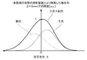
ここで、図8は、本実施の形態に係る照射装置101と比較のための照射装置とのそれぞれについて、読取領域105(X=0mm、かつ、Z=0mm)及びその上方(Zの正方向)での照度の変化を示す図である。同図では、照射装置101と比較のための照射装置とのいずれについてもZ=0mmでの照度を1として規格化している。同図から分かるように、Z方向の位置の変化に対する照度の変化は、本実施の形態に係る照射装置101による場合の方が比較のための照射装置による場合よりも小さい。
Here, FIG. 8 shows the reading area 105 (X = 0 mm and Z = 0 mm) and above (the positive direction of Z) for each of the
その結果、例えば書籍の開き目などのように、コンタクトガラス103上に設定された読取領域105から読取面が離間してしまうような場合であっても、適切に原稿104の読取面を照射することが可能になる。
As a result, even when the reading surface is separated from the
また、本実施の形態に係る照射装置101では、Y方向から見た鏡面の形状が楕円や放物線なす鏡(トロイダルミラー)ではなく、その形状が直線をなす平面鏡115を用いている。照射装置101を組み立てる場合、Y方向から見た鏡面の形状が楕円や放物線の鏡であれば鏡面の姿勢を決める6個の自由度すべてに高い精度が必要となるが、平面鏡115であれば鏡面に沿った2方向、鏡面内の回転の少なくとも3個の自由度は高い精度を必要としない。したがって、照射装置101を容易に組み立てることが可能になる。
Moreover, in the
平面鏡115は、その製造がトロイダルミラーより容易であるため安価であり、その結果、照射装置101を安価にすることが可能になる。鏡面の形状の測定も容易であるため、照射装置101の品質管理も容易にすることが可能になる。
The
第1の出射部122が平面部を有する場合、円筒状の部材の一部をY方向にカットした形状であるため、ポリカーボネートやシクロオレフィン系の樹脂で射出成形して導光体110を製作することができ、この場合、ヒケが発生しにくく、必要とする形状精度を容易に達成することが可能になる。また、導光体110の断面の形状は主に円弧と直線からなるため、形状の測定が容易で品質管理も容易にすることが可能になる。
When the first emitting
ホルダ114に嵌合部162よりも光源空間165を狭くする段差部を設け、導光体110の端面168を段差部に押し当てることで、ホルダ114に対して導光体110を位置決めして嵌め合わせることができる。また、嵌合部162は、第1の出射部122が当接する第1の当接部を有する場合、それらは平面又は導光体110の断面の概形をなす円とは異なる曲率の曲面を有することになる。この場合には、導光体110の軸126を中心とする回転方向の位置決めも容易になる。したがって、これらによっても照射装置101の組み立てを容易にすることが可能になる。
The
さらに、第1のプリズム群121及び第2のプリズム群123を構成するプリズム132は不均一なピッチで数百〜数千本Y方向に並んでおり、これによって、読取領域105におけるY方向の照度分布を目標とする分布、例えばCOS−4乗型の分布にすることが可能になる。
Furthermore, hundreds to thousands of
さらに、高い反射率を有する第1のリフレクタ111を備えることによって第1のプリズム群121を透過した光を導光体110の内部へ再入射させることができるので、第1のプリズム群121に当たった光の多くを第1の出射部122から出射させることができる。これによって、原稿104の読取面における照度を向上させることが可能になる。
Further, by providing the
第2のリフレクタ112についても同様である。すなわち、高い反射率を有する第2のリフレクタ112を備えることによって、第2のプリズム群123に当たった光の多くを第2の出射部124から出射させることができるので、原稿104の読取面における照度を向上させることが可能になる。
The same applies to the
主光Lmと副光Lsとはそれぞれ、図2に示すように右斜め下方と左斜め下方とから、読取領域105又はその上方に配置された原稿104の読取面を照射する。主光Lmと副光Lsとは原稿104の読取面で反射し、拡散する。反射光は読取面の情報に応じて反射し拡散するため、読取面の情報を含んだものとなる。反射光は、読取装置102の読取系鏡群175と光学レンズ176とを介して結像されてイメージセンサ177により受光される。イメージセンサ177は、受光した光の強度に応じた電気信号を出力する。この電気信号は、照射装置101によって主光Lmと副光Lsとが照射された部分の読取面の情報を含む画像データである。
As shown in FIG. 2, the main light L m and the sub light L s irradiate the
このようにして、読取装置102は画像データを出力する。照射装置101は例えば、図示しない駆動装置によってX方向に移動しながら原稿104の読取面の所定の領域を照射する。なお、照射装置101が移動する代わりに、原稿104が駆動装置によってX方向に搬送されてもよく、これによっても照射装置101は読取面の所定の領域を照射することができる。
In this way, the
読取装置102は、照射された部分に対応する画像データを順次出力する。順次出力される画像データはメモリに記憶され、これによって、原稿104の読取面の所定の領域に表された情報を含む画像データが生成される。ここで、順次出力される画像データを記憶するメモリは、読取装置102が備えてもよいし、読取装置102が接続される装置が備えてもよい。
The
上述のようにコンタクトガラス103上に設定された読取領域105から読取面が離間してしまうような場合であっても、良好に原稿104の読取面を照射することが可能になる。そのため、本実施の形態に係る画像読取装置100によれば、このような場合であっても濃淡の変化を少なくした良好な画像データを出力することが可能になる。
As described above, even when the reading surface is separated from the
以上、本発明の実施の形態1について説明したが、本実施の形態はこれに限られない。
As mentioned above, although
実施の形態1では、導光体110の断面が概ね円形をなす、すなわち、導光体110の断面において第1のプリズム群121と第2のプリズム群123と第1の出射部122が有する平面部136とを円形から切り欠いた形状をなす例により説明した。しかし、導光体110の断面は円形に限られない。
In the first embodiment, the
導光体110の断面は例えば楕円形であってもよい。この場合、照射装置101を組み立てる際にその導光体110の軸126を中心とした回転方向を適宜設定することによって、少なくとも一部において第2の出射部124よりも曲率が小さい第1の出射部122を実現することができる。もちろん、第1の出射部122には実施の形態1と同様に平面又は第2の出射部124よりも少なくとも一部において曲率が小さい曲面部が、例えば断面が楕円をなす棒状の部材を加工して、設けられてもよい。
The cross section of the
実施の形態1ではホルダ114の両方が光源部113を保持することとしたが、ホルダ114の一方は、光源部113を保持せずに導光体110の端部のみを保持してもよい。
In the first embodiment, both the
実施の形態1では第1のプリズム群121と第2のプリズム群123とでそれぞれを構成するプリズム132の本数を同程度とした。しかし、第2のプリズム群123のプリズム132の本数は第1のプリズム群121の本数より多い方が望ましい。
In the first embodiment, the
実施の形態1で説明したように、副光Lsは平面鏡115で反射されて読取領域105に至り、主光Lmは鏡を介することなく読取領域105に至る。そのため、平面鏡115の反射率によっては、読取領域105において副光Lsの照度は主光Lmの照度よりも低くなることがある。
As described in the first embodiment, the secondary light L s is reflected by the
そこで、上述のように、第2のプリズム群123のプリズム132の本数を第1のプリズム群121の本数より多くすることで、平面鏡115の反射率による影響を軽減し、読取領域105において主光Lmの照度と副光Lsの照度とを同程度にすることが可能になる。その結果、照明深度をさらに深くすることが可能になる。例えば平面鏡115の反射率が95%である場合、第2のプリズム群123のプリズム132の本数を第1のプリズム群121の本数より5%多くするとよい。
Therefore, as described above, the influence of the reflectance of the
実施の形態1では第1のリフレクタ111と第2のリフレクタ112とが別部材で設けられる例により説明したが、第1のプリズム群121と第2のプリズム群123を透過した光を反射するリフレクタの構成はこれに限られない。例えば変形例1に係る照射装置は、実施の形態1に係る照射装置101が備える第1のリフレクタ111と第2のリフレクタ112とに代えて、図9に示すように第1のプリズム群121と第2のプリズム群123との両方を覆う一体の部材で構成されるリフレクタ183を反射部として備える。
In the first embodiment, the example in which the
一体のリフレクタ183を採用することによって、照射装置の組み立ての工数を減らすことができるので、照射装置をより容易に組み立てることが可能になる。また、リフレクタ183が例えば白色のポリカーボネート等の樹脂で作られる場合、リフレクタ183を一体の部材とすることによって成形費用が抑えられるため、照射装置をより安価にすることが可能になる。
By adopting the
実施の形態1では、第1の拡散反射部が、第1のプリズム群121と第1のリフレクタ111とで構成され、第2の拡散反射部が第2のプリズム群123と第2のリフレクタ112とで構成されることとした。しかし、第1の拡散反射部又は第2の拡散反射部の構成はこれに限られない。
In the first embodiment, the first diffuse reflector is composed of the
例えば、第1のプリズム群121又は第2のプリズム群123を構成するプリズム132の形状によっては、第1のプリズム群121又は第2のプリズム群123のそれぞれに当たった光の多くが透過せずに反射することがある。このような場合には、第1のリフレクタ111又は第2のリフレクタ112は設けられなくてもよく、これによって、実施の形態1と同様の効果を奏することが可能になるだけでなく、照射装置の組み立てをさらに容易にすることが可能になる。また、照射装置を安価にすることが可能になる。
For example, depending on the shape of the
また例えば、第1の拡散反射部は、図10に示す変形例2に係る照射装置のように第1のリフレクタ111とともに、又は図11に示す変形例3に係る照射装置のように第1のリフレクタ111に代えて(図11参照)、導光体110の外面に長手方向に設けられた反射散乱物質を含む第1の反射散乱物質層184を備えてもよい。例えば第1の反射散乱物質層184は、第1のプリズム群121の外面の全体に、又は、第1のプリズム群121を構成するプリズム132と同様に不均一なピッチでY方向に並ぶ島状に第1のプリズム群121の外面に設けられるとよい。第1の反射散乱物質層184は例えば、反射散乱物質を含む材料を塗布することで設けることができる。ここで、反射散乱物質は光を反射し散乱させる物質であって、例えば白色の物質である。
In addition, for example, the first diffuse reflector is the
これによっても、第1のプリズム群121に当たった伝搬光Lpを第1の出射部122から出射させることができる。したがって、実施の形態1と同様の効果を奏することが可能になる。
Also by this, the propagating light L p hitting the
第2の拡散反射部が、図10に示す変形例2に係る照射装置のように第2のリフレクタ112とともに、又は図11に示す変形例3に係る照射装置のように第2のリフレクタ112に代えて、上述の第1の拡散反射部184と同様に導光体110の外面に長手方向に設けられた反射散乱物質を含む反射散乱物質層185を備えてもよい。これによっても、第2のプリズム群123に当たった伝搬光Lpを第2の出射部124から出射させることができる。したがって、実施の形態1と同様の効果を奏することが可能になる。
The second diffuse reflection portion is provided on the
第1のプリズム群121と第2のプリズム群123と両方が反射散乱物質層を備える場合、第2の拡散反射部が備える反射散乱物質層に含まれる反射散乱物質の量は、第1の拡散反射部が備える反射散乱物質層に含まれる反射散乱物質の量よりも多くてもよい。反射散乱物質の量の調整には、第1の拡散反射部と第2の拡散反射部とで反射散乱物質層のY方向のピッチ、幅などを異なるものにするなどの方法がある。
When both the
これによって、第2のプリズム群123のプリズム132の本数を第1のプリズム群121の本数より多くするのと同様に、平面鏡115の反射率による影響を軽減し、読取領域105において主光Lmの照度と副光Lsの照度とを同程度にすることが可能になる。その結果、照明深度を深くすることが可能になる。
As a result, the influence of the reflectivity of the
さらに例えば、図12に示す変形例4に係る照射装置のように第1の拡散反射部は、第1のプリズム群121及び第1リフレクタ111に代えて、導光体110の外側面に長手方向に設けられた反射散乱物質を含む第1の反射散乱物質層184で構成されてもよい。同様に、第2の拡散反射部は、第2のプリズム群123及び第2のリフレクタ112に代えて、第2の反射散乱物質層185で構成されてもよい。第1の反射散乱物質層184又は第2の反射散乱物質層185は例えば、反射散乱物質を含む材料を導光体110の外側面に塗布することで設けられるとよい。反射散乱物質は上述のように光を反射し散乱させる物質であって、例えば白色の物質である。
Further, for example, as in the irradiation device according to the modification 4 illustrated in FIG. 12, the first diffuse reflector is arranged in the longitudinal direction on the outer surface of the
これによっても、第1の拡散反射部に当たった伝搬光Lpを第1の出射部122から出射させることができる。また、第2の拡散反射部に当たった伝搬光Lpを第2の出射部124から出射させることができる。したがって、実施の形態1と同様の効果を奏することが可能になる。
Also by this, the propagation light L p hitting the first diffuse reflection part can be emitted from the
この場合、反射散乱物質層は、第1のプリズム群121又は第2のプリズム群123を構成するプリズム132と同様に、不均一なピッチでY方向に並ぶ島状に設けられることが望ましい。これによって、読取領域105におけるY方向の照度分布を目標とする分布、例えばCOS−4乗型の分布にすることが可能になる。
In this case, it is desirable that the reflection / scattering material layer is provided in the shape of islands arranged in the Y direction at a non-uniform pitch, similarly to the
第1の拡散反射部と第2の拡散反射部と両方が反射散乱物質層で構成される場合、第2の拡散反射部を構成する反射散乱物質層に含まれる反射散乱物質の量は、第1の拡散反射部のそれよりも多い方が望ましい。反射散乱物質の量の調整には、第1の拡散反射部と第2の拡散反射部とで反射散乱物質層を構成する島のY方向のピッチ、幅などを異なるものにするなどの方法がある。 When both the first diffuse reflection part and the second diffuse reflection part are composed of the reflective scattering material layer, the amount of the reflective scattering material included in the reflective scattering material layer constituting the second diffuse reflection part is: It is desirable that there be more than that of one diffuse reflection part. In adjusting the amount of the reflective / scattering substance, there is a method in which the first diffusion reflection part and the second diffuse reflection part have different pitches and widths in the Y direction of the islands constituting the reflection / scattering substance layer. is there.
これによって、第2のプリズム群123のプリズム132の本数を第1のプリズム群121の本数より多くするのと同様に、平面鏡115の反射率による影響を軽減し、例えばコンタクトガラス103の上面において副光Lsの照度と主光Lmの照度とを同程度にすることが可能になる。その結果、照明深度を深くすることが可能になる。
This reduces the influence of the reflectivity of the
実施の形態2.
本実施の形態では導光体とホルダとが、実施の形態1に係る導光体110とホルダ114とは異なる。本実施の形態に係る導光体210の端部は、図13に示すように、切欠部285を備える。切欠部285は、導光体210の端面168からY方向に延びる平面を形成する。切欠部285は、第1の出射部122と異なる部分に設けられる。切欠部285のY方向の長さは、導光体210がホルダ214の嵌合部262と嵌合する長さと同じかそれよりも僅かに長い。
Embodiment 2. FIG.
In the present embodiment, the light guide and the holder are different from the
ホルダ214は、実施の形態1に係るホルダ114と概ね同様の構成を備えており、ホルダ214の嵌合部262が形成する孔の形状が実施の形態1に係るホルダ114の孔と異なる。嵌合部262は、Y方向から見た場合に、導光体210の断面の概形をなす円より僅かに大きいか、それと同程度の概ね円形をなす孔を形成する。嵌合部262は、導光体210の端部が嵌合した場合に第1の出射部122が当接する実施の形態1と同様の第1の当接部286に加えて、導光体210の端部が嵌合した場合に切欠部285が当接する第2の当接部287を備える。
The
ホルダ214はさらに、図13に示すように、付勢部291を備える。付勢部291は、導光体110の端部が嵌合した場合に第1の出射部122を第1の当接部286へ押圧するとともに切欠部285を第2の当接部287へ押圧する方向へ導光体210の端部の外側面を付勢する。
The
詳細には例えば、付勢部291は、樹脂製のピン292と、嵌合部262の孔のY方向から見た概形を形成する円の中心へ向けてピン292を付勢する金属製のバネとから構成される。ピン292は、Y方向から見た場合に、嵌合部262の孔のY方向から見た概形を形成する円の中心を介して第1の当接部286と反対側の位置と、その中心を介して第2の当接部287と反対側の位置との間(望ましくはその中間)で、第1の当接部286及び第2の当接部287を含まない側の領域に配置されるとよい。なお、付勢部291は、例えば射出成形などによって、ホルダ214と一体で設けられてもよい。
Specifically, for example, the urging
これによって、1つの付勢部291によって、導光体110の端部が嵌合した場合に第1の出射部122を第1の当接部286へ押圧するとともに切欠部285を第2の当接部287へ押圧する方向へ導光体210の端部の外側面を付勢することが可能になる。なお、付勢部291は複数設けられてもよい。
Accordingly, when the end portion of the
本実施の形態によれば、導光体210の端部が嵌合した場合、第1の出射部122及び切欠部285のそれぞれは第1の当接部286及び第2の当接部287に押圧される。そのため、導光体210のY方向に垂直な面内における位置が定まり、同時に導光体210の軸を中心とした回転方向の角度も定まる。したがって、本実施の形態に係る照射装置201を組み立てる場合に、導光体210のY方向に垂直な面内における位置と導光体210の軸126を中心とした回転方向の角度とを容易に決定することが可能になる。その結果、原稿104の読取面におけるX方向の照度分布において個体差の少ない照射装置201を安定して製造することが可能になる。
According to the present embodiment, when the end of the
また、導光体210がポリカーボネートやシクロオレフィン系の樹脂を射出成形して製作される場合、導光体210の外面のどこかにゲートが必要になる。本実施の形態では、ゲートは、図14に点線の楕円296で囲んで示すように、導光体210の外側面のうち切欠部285の近傍であって、切欠部285から導光体210のY方向に沿って中心側の伝搬光Lpが照射しない領域(遮光領域)に設けられるとよい。
Further, when the
一般に導光体210の内面でほぼ全反射させて伝搬光Lpを伝搬させるために、導光体210の内面は鏡面であることが望ましく、鏡面を崩すことになるゲートの設置箇所は注意深く決定される。例えば端面、第1のプリズム群121、第2のプリズム群123、及びY方向の中央付近の外側面は、読取領域105の照度又は照度分布に影響するため、このような領域にゲートを設けることは避けられる。
In general, the inner surface of the
例えば実施の形態1の場合、ゲートは例えば導光体110の外側面のうち、導光体110の端面168に近い領域(端部)に設けられることが多い。しかし、この領域はLED151から端面168に対し平行に近い、すなわち浅い角度で入射した光が本来最初に全反射される部分である。そのため、導光体110の端部の外側面にゲートを設けると、特にY方向の両端近傍における読取領域105の照度又は照度分布に悪影響を及ぼすことがある。
For example, in the case of
本実施の形態によれば、図14に示すように、切欠部285と導光体210の外側面とを接続する段差を形成する接続部294がホルダ114と当接又は近接する。そのため、同図に示すように、点線の楕円296で囲んだ範囲に含まれる導光体210の外側面は、導光体210の端部がホルダに嵌合した場合に伝搬光Lpが遮られる遮光領域となる。
According to the present embodiment, as shown in FIG. 14, the
このように、本実施の形態では、遮光領域にゲートを設けることによって、読取領域105の照度又は照度分布に影響を与えることがなく、読取領域105の全体にわたって良好な照度及び照度分布を得ることが可能になる。
As described above, in this embodiment, by providing the gate in the light shielding area, the illuminance or illuminance distribution of the
以上、本発明の実施の形態及び変形例について説明したが、本発明は、実施の形態及び変形例に限定されるものではなく、例えば各実施の形態及び各変形例を適宜組み合わせた態様、またそれらと均等な技術的範囲をも含む。 As mentioned above, although embodiment and the modification of this invention were demonstrated, this invention is not limited to embodiment and the modification, For example, the aspect which combined each embodiment and each modification suitably, Including the technical scope equivalent to them.
本発明に係る照射装置及び画像読取装置は、例えば複写機、スキャナ、紙幣や有価証券の画像を読み取ることでその真偽を識別する装置などに適用することができる。 The irradiation apparatus and the image reading apparatus according to the present invention can be applied to, for example, a copying machine, a scanner, and an apparatus for identifying authenticity by reading an image of banknotes or securities.
100 画像読取装置
101,201 照射装置
102 読取装置
103 コンタクトガラス
104 原稿
105 読取領域
110,210 導光体
111 第1のリフレクタ
112 第2のリフレクタ
113 光源部
114,214 ホルダ
115 平面鏡
121 第1のプリズム群
122 第1の出射部
123 第2のプリズム群
124 第2の出射部
136 平面部
137 円周部
151 LED
152 基板
161 光源取付部
162,262 嵌合部
183 リフレクタ
184 第1の反射散乱物質層
185 第2の反射散乱物質層
285 切欠部
286 第1の当接部
287 第2の当接部
291 付勢部
DESCRIPTION OF
152
Claims (12)
断面の概形となる円の半径がRであって、前記光源部が端部近傍に配置される透明な棒状の導光体と、
前記導光体の長手方向に延びて設けられており、前記導光体の内部を伝搬する光を拡散して反射させる第1の拡散反射部と、
前記第1の拡散反射部の反射方向にある前記導光体の外面で前記長手方向に延びる部分であって、前記第1の拡散反射部により反射された光を主光として出射させる第1の出射部と、
前記導光体の前記長手方向に延びて設けられており、前記導光体の内部を伝搬する光を拡散して反射させる第2の拡散反射部と、
前記第2の拡散反射部の反射方向にある前記導光体の外面で前記長手方向に延びる部分であって、前記第2の拡散反射部により反射された光を副光として出射させる第2の出射部と、
所定の領域において前記主光と重なり合う方向へ前記副光を反射する平面鏡とを備え、
前記第2の出射部は、前記長手方向から見た形状が1/Rの曲率の曲線であり、
前記第1の出射部は、平面又は前記長手方向から見て前記第2の出射部の曲率である1/Rの曲率より小さい曲率で定義された凸形状の曲面であり、
前記主光は前記副光よりも広い発散角を有する照射装置。 A light source that emits light;
A transparent rod-shaped light guide body in which the radius of a circle that is an outline of a cross section is R, and the light source part is disposed in the vicinity of the end part;
A first diffusive reflection part that extends in the longitudinal direction of the light guide and diffuses and reflects light propagating through the light guide;
A portion extending in the longitudinal direction on the outer surface of the light guide in the reflection direction of the first diffuse reflection portion, wherein the light reflected by the first diffuse reflection portion is emitted as main light. An emission part;
A second diffusive reflecting portion that extends in the longitudinal direction of the light guide and diffuses and reflects light propagating through the light guide;
A portion extending in the longitudinal direction on the outer surface of the light guide in the reflection direction of the second diffuse reflection portion, wherein the light reflected by the second diffuse reflection portion is emitted as secondary light. An emission part;
A plane mirror that reflects the sub-light in a direction overlapping the main light in a predetermined region;
The second emission part is a curve having a curvature of 1 / R as viewed from the longitudinal direction,
The first emission part is a convex curved surface defined with a curvature smaller than a curvature of 1 / R which is a curvature of the second emission part as seen from a plane or the longitudinal direction,
The main light has a wider divergence angle than the auxiliary light.
前記光源部が端部近傍に配置される透明な棒状の導光体と、
前記導光体の長手方向に延びて設けられており、前記導光体の内部を伝搬する光を拡散して反射させる第1の拡散反射部と、
前記第1の拡散反射部の反射方向にある前記導光体の外面で前記長手方向に延びる部分であって、前記第1の拡散反射部により反射された光を主光として出射させる第1の出射部と、
前記導光体の前記長手方向に延びて設けられており、前記導光体の内部を伝搬する光を拡散して反射させる第2の拡散反射部と、
前記第2の拡散反射部の反射方向にある前記導光体の外面で前記長手方向に延びる部分であって、前記第2の拡散反射部により反射された光を副光として出射させる第2の出射部と、
所定の領域において前記主光と重なり合う方向へ前記副光を反射する平面鏡と、
前記導光体の外面の前記第1の出射部とは異なる部分に設けられており、前記長手方向に延びる平面を有する切欠部と、
前記光源部と前記導光体とを保持するホルダとを備え、
前記第2の出射部は、前記長手方向から見た形状が曲線であり、
前記第1の出射部は、平面又は前記長手方向から見て前記第2の出射部より小さい曲率の曲線をなす部分を少なくとも一部に含み、
前記主光は前記副光よりも広い発散角を有し、
前記ホルダは、
前記光源部が取り付けられる光源取付部と、
前記光源部が発する光が通過する光源空間と連通し、前記導光体の端部が前記長手方向に挿入される孔を形成し、それによって前記導光体の端部と嵌合する嵌合部と、
前記嵌合部に形成される面であって、前記第1の出射部が当接する第1の当接部と、
前記嵌合部に形成される平面であって、前記切欠部が当接する第2の当接部と、
前記導光体の端部が前記嵌合部に嵌合している場合に、前記第1の出射部を前記第1の当接部へ押圧するとともに前記切欠部を前記第2の当接部へ押圧する方向へ前記導光体の端部を付勢する付勢部とを備える
ことを特徴とする照射装置。 A light source that emits light;
A transparent rod-shaped light guide body in which the light source unit is disposed near the end,
A first diffusive reflection part that extends in the longitudinal direction of the light guide and diffuses and reflects light propagating through the light guide;
A portion extending in the longitudinal direction on the outer surface of the light guide in the reflection direction of the first diffuse reflection portion, wherein the light reflected by the first diffuse reflection portion is emitted as main light. An emission part;
A second diffusive reflecting portion that extends in the longitudinal direction of the light guide and diffuses and reflects light propagating through the light guide;
A portion extending in the longitudinal direction on the outer surface of the light guide in the reflection direction of the second diffuse reflection portion, wherein the light reflected by the second diffuse reflection portion is emitted as secondary light. An emission part;
A plane mirror that reflects the sub-light in a direction overlapping the main light in a predetermined region;
A notch having a plane extending in the longitudinal direction, provided in a portion different from the first emitting portion on the outer surface of the light guide;
A holder for holding the light source unit and the light guide;
The second emission part has a curved shape when viewed from the longitudinal direction,
The first emission part includes at least a part forming a curve with a curvature smaller than that of the second emission part when viewed from the plane or the longitudinal direction,
The main light has a wider divergence angle than the sub-light,
The holder is
A light source attachment part to which the light source part is attached;
The light source part communicates with the light source space through which light passes, and the end of the light guide forms a hole inserted in the longitudinal direction, thereby fitting with the end of the light guide And
A first contact portion which is a surface formed in the fitting portion and is in contact with the first emission portion;
A flat surface formed in the fitting portion, the second contact portion with which the notch portion contacts,
When the end portion of the light guide is fitted to the fitting portion, the first emitting portion is pressed against the first abutting portion, and the notch portion is pushed to the second abutting portion. irradiation morphism device anda biasing unit that biases the end portion of the light guide in a direction to press the.
前記導光体は、さらに、前記切欠部の近傍であって、前記長手方向に前記切欠部よりも前記導光体の中心側に射出成型用のゲートが設けられている
ことを特徴とする請求項2に記載の照射装置。 The notch has a plane extending in the longitudinal direction with a length corresponding to the length in the longitudinal direction of the light guide body fitted into the fitting portion,
The light guide is further provided with a gate for injection molding in the vicinity of the notch and in the longitudinal direction on the center side of the light guide with respect to the notch. Item 3. The irradiation apparatus according to Item 2 .
ことを特徴とする請求項1から3のいずれか1項に記載の照射装置。 One or both of said first diffusion reflectors the second diffusion reflectors from claim 1, characterized in that it comprises a prism group disposed in a region extending in the longitudinal direction of the light guide irradiation apparatus according to any one of 3.
前記第2の拡散反射部が備えるプリズム群に含まれるプリズムの数は、前記第1の拡散反射部が備えるプリズム群に含まれるプリズムの数よりも多い
ことを特徴とする請求項4に記載の照射装置。 Both the first diffuse reflection portion and the second diffuse reflection portion include the prism group,
The number of prisms included in the prism group that said second diffusion reflectors are provided is according to claim 4, characterized in that more than the number of prisms included in the prism group that the first diffusion reflectors are provided Irradiation device.
ことを特徴とする請求項4又は5に記載の照射装置。 One or both of said second diffuse reflection portion and the first diffusion reflectors comprising the prism group further, according to claim 4 or 5, characterized in that a reflective portion that covers the prism group Irradiation equipment.
前記反射部は一体で前記プリズム群の両方を覆う
請求項6に記載の照射装置。 Both the first diffuse reflection part and the second diffuse reflection part include the reflection part,
The reflection part is integrated and covers both the prism groups.
Irradiation apparatus according to 請 Motomeko 6.
ことを特徴とする請求項4から7のいずれか1項に記載の照射装置。 One or both of the first diffuse reflection unit and the second diffuse reflection unit including the prism group further includes a reflection / scattering material layer including a reflection / scattering material on an outer surface of the prism group. The irradiation apparatus according to any one of claims 4 to 7 .
前記第2の拡散反射部が備える反射散乱物質層に含まれる反射散乱物質の量は、前記第1の拡散反射部が備える反射散乱物質層に含まれる反射散乱物質の量よりも多い
ことを特徴とする請求項8に記載の照射装置。 Both the first diffuse reflection part and the second diffuse reflection part include the reflective scattering material layer,
The amount of the reflection / scattering substance contained in the reflection / scattering substance layer provided in the second diffuse reflection part is larger than the amount of the reflection / scattering substance contained in the reflection / scattering substance layer provided in the first diffuse reflection part. The irradiation apparatus according to claim 8 .
ことを特徴とする請求項1から3のいずれか1項に記載の照射装置。 The first diffuse reflection part and the second diffuse reflection part are reflection / scattering substance layers including a reflection / scattering substance provided in a region extending in the longitudinal direction on the outer surface of the light guide. The irradiation apparatus according to any one of claims 1 to 3 .
ことを特徴とする請求項10に記載の照射装置。 The irradiation apparatus according to claim 10 , wherein the amount of the reflection / scattering substance forming the second diffuse reflection part is larger than the amount of the reflection / scattering substance forming the first diffuse reflection part.
前記照射装置から照射された光が対象物で反射した光を受けて画像データを出力する読取装置とを備える
ことを特徴とする画像読取装置。 The irradiation apparatus according to any one of claims 1 to 11 ,
An image reading apparatus comprising: a reading device that receives light reflected from an object and outputs image data.
Priority Applications (7)
| Application Number | Priority Date | Filing Date | Title |
|---|---|---|---|
| JP2012016130A JP5963455B2 (en) | 2012-01-30 | 2012-01-30 | Irradiation apparatus and image reading apparatus |
| CN201280068441.4A CN104081116B (en) | 2012-01-30 | 2012-12-03 | Irradiation unit and image read-out |
| EP12867432.2A EP2811221B1 (en) | 2012-01-30 | 2012-12-03 | Irradiation device and image-reading device |
| PCT/JP2012/081258 WO2013114720A1 (en) | 2012-01-30 | 2012-12-03 | Irradiation device and image-reading device |
| KR1020147018234A KR20140104002A (en) | 2012-01-30 | 2012-12-03 | Irradiation device and image-reading device |
| US14/371,079 US9329333B2 (en) | 2012-01-30 | 2012-12-03 | Irradiation device and image-reading device |
| TW102101583A TW201345228A (en) | 2012-01-30 | 2013-01-16 | Irradiation device and image-reading device |
Applications Claiming Priority (1)
| Application Number | Priority Date | Filing Date | Title |
|---|---|---|---|
| JP2012016130A JP5963455B2 (en) | 2012-01-30 | 2012-01-30 | Irradiation apparatus and image reading apparatus |
Publications (3)
| Publication Number | Publication Date |
|---|---|
| JP2013157163A JP2013157163A (en) | 2013-08-15 |
| JP2013157163A5 JP2013157163A5 (en) | 2015-02-26 |
| JP5963455B2 true JP5963455B2 (en) | 2016-08-03 |
Family
ID=48904782
Family Applications (1)
| Application Number | Title | Priority Date | Filing Date |
|---|---|---|---|
| JP2012016130A Active JP5963455B2 (en) | 2012-01-30 | 2012-01-30 | Irradiation apparatus and image reading apparatus |
Country Status (7)
| Country | Link |
|---|---|
| US (1) | US9329333B2 (en) |
| EP (1) | EP2811221B1 (en) |
| JP (1) | JP5963455B2 (en) |
| KR (1) | KR20140104002A (en) |
| CN (1) | CN104081116B (en) |
| TW (1) | TW201345228A (en) |
| WO (1) | WO2013114720A1 (en) |
Families Citing this family (16)
| Publication number | Priority date | Publication date | Assignee | Title |
|---|---|---|---|---|
| JP6145791B2 (en) * | 2014-08-20 | 2017-06-14 | コニカミノルタ株式会社 | Light guide, illumination device, and image reading device |
| JP2017535922A (en) | 2014-11-12 | 2017-11-30 | スリーエム イノベイティブ プロパティズ カンパニー | Illumination system including a light guide |
| WO2016077110A1 (en) * | 2014-11-12 | 2016-05-19 | 3M Innovative Properties Company | Illumination system including lightguide |
| JP6579863B2 (en) * | 2015-08-27 | 2019-09-25 | キヤノン・コンポーネンツ株式会社 | Reader and transmission light source unit |
| JP6350506B2 (en) * | 2015-12-15 | 2018-07-04 | コニカミノルタ株式会社 | Image reading apparatus and image forming system |
| US10718890B2 (en) * | 2016-03-01 | 2020-07-21 | 3M Innovative Properties Company | Optical structures with off-state appearance area |
| JP6634896B2 (en) * | 2016-03-09 | 2020-01-22 | 株式会社リコー | Light irradiation device, image reading device, and image forming device |
| US11382203B2 (en) | 2016-09-05 | 2022-07-05 | Signify Holding B.V. | Systems, methods, and apparatuses for distributing computational resources over a network of luminaires |
| JP6739138B2 (en) * | 2016-11-30 | 2020-08-12 | ダイハツ工業株式会社 | Lighting equipment |
| WO2019003480A1 (en) | 2017-06-28 | 2019-01-03 | 三菱電機株式会社 | Light guide body and image reading apparatus |
| JP6395988B1 (en) * | 2017-06-28 | 2018-09-26 | 三菱電機株式会社 | Light guide and image reading apparatus |
| US10533731B2 (en) * | 2017-07-11 | 2020-01-14 | Valeo North America, Inc. | Bi-material transmitting optical element |
| CN108609868B (en) * | 2018-07-17 | 2024-04-30 | 四川乐飞光电科技有限公司 | Novel optical fiber coloring curing oven |
| US10739513B2 (en) | 2018-08-31 | 2020-08-11 | RAB Lighting Inc. | Apparatuses and methods for efficiently directing light toward and away from a mounting surface |
| US10801679B2 (en) | 2018-10-08 | 2020-10-13 | RAB Lighting Inc. | Apparatuses and methods for assembling luminaires |
| JP7461172B2 (en) * | 2020-03-02 | 2024-04-03 | グローリー株式会社 | Illumination device for image sensors |
Family Cites Families (35)
| Publication number | Priority date | Publication date | Assignee | Title |
|---|---|---|---|---|
| DE69435168D1 (en) * | 1993-01-19 | 2009-01-02 | Canon Kk | An elongated lighting device and information reading device comprising such a lighting device |
| US6268600B1 (en) * | 1994-08-01 | 2001-07-31 | Matsushita Electric Industrial Co., Ltd. | Linear illumination device |
| US6236470B1 (en) * | 1994-12-19 | 2001-05-22 | Xerox Corporation | Reflector and light source registration device for a document illuminator |
| JPH10133026A (en) * | 1996-10-31 | 1998-05-22 | Canon Inc | Illuminator having light transmission body |
| JP3862422B2 (en) * | 1998-07-10 | 2006-12-27 | キヤノン株式会社 | Image reading device |
| JP2001148767A (en) | 1999-11-22 | 2001-05-29 | Canon Inc | Image reader and shading correcting method |
| US6728010B1 (en) * | 2000-09-19 | 2004-04-27 | Kabushiki Kaisha Toshiba | Color image reader for use in image forming apparatus |
| JP3543756B2 (en) * | 2000-11-02 | 2004-07-21 | 日本電気株式会社 | Document reading device |
| NL1019039C2 (en) * | 2001-09-26 | 2003-03-27 | Interlogix B V | Surveillance detector. |
| JP2003346509A (en) | 2002-03-19 | 2003-12-05 | Keiden Koden Kofun Yugenkoshi | Linear light source for image scanner and liquid crystal module |
| EP1511289B1 (en) * | 2003-08-19 | 2011-11-23 | Ricoh Company, Ltd. | Lighting device, image reading apparatus , and image forming apparatus |
| WO2007105293A1 (en) * | 2006-03-13 | 2007-09-20 | Canon Components, Inc. | Linear illuminating apparatus and image reader using it |
| WO2008108210A1 (en) * | 2007-02-26 | 2008-09-12 | Rohm Co., Ltd. | Linear light source apparatus and image reading apparatus provided with the same |
| JP4793288B2 (en) * | 2007-03-01 | 2011-10-12 | ウシオ電機株式会社 | Light guide and bifurcated linear light source device |
| JP4396715B2 (en) | 2007-03-01 | 2010-01-13 | 三菱電機株式会社 | Image sensor |
| JP5087337B2 (en) * | 2007-07-25 | 2012-12-05 | スタンレー電気株式会社 | Document reading light source device |
| US9172836B2 (en) * | 2007-08-28 | 2015-10-27 | Hewlett-Packard Development Company, Lp. | Optical scanner illumination system and method |
| JP5288880B2 (en) * | 2008-05-21 | 2013-09-11 | 京セラドキュメントソリューションズ株式会社 | Image reading apparatus and image forming apparatus |
| JP5264338B2 (en) * | 2008-07-17 | 2013-08-14 | 京セラドキュメントソリューションズ株式会社 | Image reading apparatus and image forming apparatus |
| JP2010103034A (en) * | 2008-10-27 | 2010-05-06 | Ushio Inc | Linear light source device |
| ATE547745T1 (en) * | 2009-04-17 | 2012-03-15 | Toshiba Kk | LIGHTING DEVICE AND IMAGE READING DEVICE |
| TW201109588A (en) * | 2009-09-10 | 2011-03-16 | E Pin Optical Industry Co Ltd | Light guide with taped saw tooth for linear light source |
| JP4757340B2 (en) * | 2009-10-30 | 2011-08-24 | シャープ株式会社 | Illumination apparatus, image reading apparatus including the illumination apparatus, and image forming apparatus including the image reading apparatus |
| JP5573107B2 (en) * | 2009-11-04 | 2014-08-20 | ウシオ電機株式会社 | Lighting device |
| JP5533505B2 (en) * | 2009-12-18 | 2014-06-25 | ウシオ電機株式会社 | Linear light source |
| JP5037637B2 (en) * | 2010-02-16 | 2012-10-03 | シャープ株式会社 | Illumination apparatus, image reading apparatus including the illumination apparatus, and image forming apparatus including the image reading apparatus |
| JP5071495B2 (en) * | 2010-03-04 | 2012-11-14 | ウシオ電機株式会社 | Light source device |
| JP5484405B2 (en) * | 2011-06-14 | 2014-05-07 | 富士通株式会社 | Illumination device and liquid crystal display device |
| EP2813754B1 (en) * | 2012-02-07 | 2020-01-22 | Mitsubishi Electric Corporation | Light-source device |
| EP2916064B1 (en) * | 2012-02-07 | 2021-11-17 | Mitsubishi Electric Corporation | Light source device and reflector support structure |
| JP5995459B2 (en) * | 2012-02-24 | 2016-09-21 | キヤノン株式会社 | Light guide, illumination device, and image reading device |
| US9363405B2 (en) * | 2013-03-13 | 2016-06-07 | Ricoh Company | Light irradiation system, image scanning apparatus, and image forming apparatus |
| JP2014232982A (en) * | 2013-05-29 | 2014-12-11 | ウシオ電機株式会社 | Linear light source device for reading device |
| JP5970420B2 (en) * | 2013-05-31 | 2016-08-17 | 京セラドキュメントソリューションズ株式会社 | Light guide and lighting device |
| EP2808741B1 (en) * | 2013-05-31 | 2019-05-08 | Kyocera Document Solutions Inc. | Light guide and illumination device |
-
2012
- 2012-01-30 JP JP2012016130A patent/JP5963455B2/en active Active
- 2012-12-03 US US14/371,079 patent/US9329333B2/en active Active
- 2012-12-03 EP EP12867432.2A patent/EP2811221B1/en active Active
- 2012-12-03 WO PCT/JP2012/081258 patent/WO2013114720A1/en active Application Filing
- 2012-12-03 CN CN201280068441.4A patent/CN104081116B/en active Active
- 2012-12-03 KR KR1020147018234A patent/KR20140104002A/en not_active IP Right Cessation
-
2013
- 2013-01-16 TW TW102101583A patent/TW201345228A/en unknown
Also Published As
| Publication number | Publication date |
|---|---|
| EP2811221A4 (en) | 2016-01-13 |
| EP2811221B1 (en) | 2018-01-24 |
| WO2013114720A1 (en) | 2013-08-08 |
| CN104081116A (en) | 2014-10-01 |
| CN104081116B (en) | 2017-09-05 |
| JP2013157163A (en) | 2013-08-15 |
| US9329333B2 (en) | 2016-05-03 |
| KR20140104002A (en) | 2014-08-27 |
| EP2811221A1 (en) | 2014-12-10 |
| TW201345228A (en) | 2013-11-01 |
| US20140355078A1 (en) | 2014-12-04 |
Similar Documents
| Publication | Publication Date | Title |
|---|---|---|
| JP5963455B2 (en) | Irradiation apparatus and image reading apparatus | |
| TWI461636B (en) | Light source device | |
| JP4793288B2 (en) | Light guide and bifurcated linear light source device | |
| US9462150B2 (en) | Image read-in device with fastener to fasten transparent member retaining lens array assembly and light shield to board | |
| JP4576491B1 (en) | Light emitting device | |
| JP5494397B2 (en) | LED linear light source and reader | |
| JP5533505B2 (en) | Linear light source | |
| JP4868062B2 (en) | Illumination device and image reading device using the same | |
| JPWO2006049206A1 (en) | Illumination device and image reading device using the same | |
| JP7283210B2 (en) | Image reader | |
| US20130176727A1 (en) | Segmented spotlight having narrow beam size and high lumen output | |
| WO2019003480A1 (en) | Light guide body and image reading apparatus | |
| JP2000021221A (en) | Linear lighting system | |
| JP2008275689A (en) | Light guide member and linear light source device | |
| JP6129602B2 (en) | Document reading light source device | |
| JP2009272215A (en) | Light guide, illumination unit, and illumination device for image reading | |
| JP2012074857A (en) | Lighting system, and image sensor using the same | |
| JP2015231163A (en) | Image reading apparatus | |
| JP2010045755A (en) | Illuminator and image reading apparatus using the same | |
| JP2005085580A (en) | Surface lighting system, and light guide plate | |
| JP6395988B1 (en) | Light guide and image reading apparatus | |
| JP2015015510A (en) | Linear light source device for reading image | |
| KR101158960B1 (en) | Light guide and two branch line shape light source | |
| JP2008035462A (en) | Linear light source device and image reading linear light source device | |
| CN115336241B (en) | Illumination device and image scanner |
Legal Events
| Date | Code | Title | Description |
|---|---|---|---|
| A521 | Request for written amendment filed |
Free format text: JAPANESE INTERMEDIATE CODE: A523 Effective date: 20150106 |
|
| A621 | Written request for application examination |
Free format text: JAPANESE INTERMEDIATE CODE: A621 Effective date: 20150106 |
|
| A131 | Notification of reasons for refusal |
Free format text: JAPANESE INTERMEDIATE CODE: A131 Effective date: 20151006 |
|
| A521 | Request for written amendment filed |
Free format text: JAPANESE INTERMEDIATE CODE: A523 Effective date: 20151202 |
|
| TRDD | Decision of grant or rejection written | ||
| A01 | Written decision to grant a patent or to grant a registration (utility model) |
Free format text: JAPANESE INTERMEDIATE CODE: A01 Effective date: 20160531 |
|
| A61 | First payment of annual fees (during grant procedure) |
Free format text: JAPANESE INTERMEDIATE CODE: A61 Effective date: 20160628 |
|
| R150 | Certificate of patent or registration of utility model |
Ref document number: 5963455 Country of ref document: JP Free format text: JAPANESE INTERMEDIATE CODE: R150 |
|
| R250 | Receipt of annual fees |
Free format text: JAPANESE INTERMEDIATE CODE: R250 |
|
| R250 | Receipt of annual fees |
Free format text: JAPANESE INTERMEDIATE CODE: R250 |
|
| R250 | Receipt of annual fees |
Free format text: JAPANESE INTERMEDIATE CODE: R250 |
|
| R250 | Receipt of annual fees |
Free format text: JAPANESE INTERMEDIATE CODE: R250 |
|
| R250 | Receipt of annual fees |
Free format text: JAPANESE INTERMEDIATE CODE: R250 |