JP5962020B2 - Robot control apparatus, robot system, robot, and robot control method - Google Patents
Robot control apparatus, robot system, robot, and robot control method Download PDFInfo
- Publication number
- JP5962020B2 JP5962020B2 JP2012006776A JP2012006776A JP5962020B2 JP 5962020 B2 JP5962020 B2 JP 5962020B2 JP 2012006776 A JP2012006776 A JP 2012006776A JP 2012006776 A JP2012006776 A JP 2012006776A JP 5962020 B2 JP5962020 B2 JP 5962020B2
- Authority
- JP
- Japan
- Prior art keywords
- control
- force
- robot
- external force
- unit
- Prior art date
- Legal status (The legal status is an assumption and is not a legal conclusion. Google has not performed a legal analysis and makes no representation as to the accuracy of the status listed.)
- Expired - Fee Related
Links
- 238000000034 method Methods 0.000 title claims description 98
- 238000012937 correction Methods 0.000 claims description 120
- 238000006073 displacement reaction Methods 0.000 claims description 106
- 230000008859 change Effects 0.000 claims description 102
- 238000012545 processing Methods 0.000 claims description 74
- 230000008569 process Effects 0.000 claims description 55
- 238000001514 detection method Methods 0.000 claims description 24
- 230000015654 memory Effects 0.000 claims description 8
- 230000004044 response Effects 0.000 description 35
- 230000000875 corresponding effect Effects 0.000 description 14
- 230000006870 function Effects 0.000 description 11
- 238000006243 chemical reaction Methods 0.000 description 8
- 239000012636 effector Substances 0.000 description 8
- 238000010586 diagram Methods 0.000 description 7
- 230000007246 mechanism Effects 0.000 description 6
- 238000012986 modification Methods 0.000 description 6
- 230000004048 modification Effects 0.000 description 6
- 230000001276 controlling effect Effects 0.000 description 5
- 230000004043 responsiveness Effects 0.000 description 3
- 230000000694 effects Effects 0.000 description 2
- 239000000523 sample Substances 0.000 description 2
- 230000007704 transition Effects 0.000 description 2
- 230000002159 abnormal effect Effects 0.000 description 1
- 230000005856 abnormality Effects 0.000 description 1
- 230000001133 acceleration Effects 0.000 description 1
- 230000008901 benefit Effects 0.000 description 1
- 229910002056 binary alloy Inorganic materials 0.000 description 1
- 238000007796 conventional method Methods 0.000 description 1
- 230000002596 correlated effect Effects 0.000 description 1
- 238000013461 design Methods 0.000 description 1
- 238000003384 imaging method Methods 0.000 description 1
- 230000010365 information processing Effects 0.000 description 1
- 230000003993 interaction Effects 0.000 description 1
- 238000005070 sampling Methods 0.000 description 1
- 210000000707 wrist Anatomy 0.000 description 1
Images
Classifications
-
- B—PERFORMING OPERATIONS; TRANSPORTING
- B25—HAND TOOLS; PORTABLE POWER-DRIVEN TOOLS; MANIPULATORS
- B25J—MANIPULATORS; CHAMBERS PROVIDED WITH MANIPULATION DEVICES
- B25J9/00—Programme-controlled manipulators
- B25J9/16—Programme controls
- B25J9/1628—Programme controls characterised by the control loop
- B25J9/1633—Programme controls characterised by the control loop compliant, force, torque control, e.g. combined with position control
-
- B—PERFORMING OPERATIONS; TRANSPORTING
- B25—HAND TOOLS; PORTABLE POWER-DRIVEN TOOLS; MANIPULATORS
- B25J—MANIPULATORS; CHAMBERS PROVIDED WITH MANIPULATION DEVICES
- B25J9/00—Programme-controlled manipulators
- B25J9/16—Programme controls
- B25J9/1612—Programme controls characterised by the hand, wrist, grip control
-
- G—PHYSICS
- G05—CONTROLLING; REGULATING
- G05B—CONTROL OR REGULATING SYSTEMS IN GENERAL; FUNCTIONAL ELEMENTS OF SUCH SYSTEMS; MONITORING OR TESTING ARRANGEMENTS FOR SUCH SYSTEMS OR ELEMENTS
- G05B2219/00—Program-control systems
- G05B2219/30—Nc systems
- G05B2219/39—Robotics, robotics to robotics hand
- G05B2219/39322—Force and position control
-
- G—PHYSICS
- G05—CONTROLLING; REGULATING
- G05B—CONTROL OR REGULATING SYSTEMS IN GENERAL; FUNCTIONAL ELEMENTS OF SUCH SYSTEMS; MONITORING OR TESTING ARRANGEMENTS FOR SUCH SYSTEMS OR ELEMENTS
- G05B2219/00—Program-control systems
- G05B2219/30—Nc systems
- G05B2219/39—Robotics, robotics to robotics hand
- G05B2219/39343—Force based impedance control
Landscapes
- Engineering & Computer Science (AREA)
- Robotics (AREA)
- Mechanical Engineering (AREA)
- Health & Medical Sciences (AREA)
- General Health & Medical Sciences (AREA)
- Orthopedic Medicine & Surgery (AREA)
- Manipulator (AREA)
- Numerical Control (AREA)
Description
本発明は、ロボット制御装置、ロボットシステム、ロボット及びロボット制御方法等に関係する。
The present invention relates to a robot control device, a robot system , a robot, a robot control method, and the like.
マニピュレーター等のロボットを用いて行う作業において、種々の拘束条件、例えば物体との接触を伴う作業がある。このような場合においては、位置の制御に加えて、力の制御が要求される場合が多い。例えば、物体の表面をなぞる場合、1つの物体を他の物体に嵌め合わせる場合、柔軟物を破壊しないように把持する場合などにおいては、単なる位置の制御に加えて、物体からの反力に対応した動きが必要となる。 In operations performed using a robot such as a manipulator, there are various constraints such as operations involving contact with an object. In such cases, force control is often required in addition to position control. For example, when tracing the surface of an object, fitting one object to another object, gripping a flexible object without destroying it, etc., in addition to simply controlling the position, respond to the reaction force from the object Movement is required.
ロボットにおいて力制御を行う代表的な手法としては、インピーダンス制御と呼ばれる手法がある。インピーダンス制御とは、ロボットを、その実際の質量や粘性特性や弾性特性に関わらず、あたかも作業に適したそれらの値を持つかのように動作させる制御手法である。これは、ロボットに取り付けられた力覚センサーなどから得られる力情報に基づいて運動方程式を解き、ロボットをその解に従って動作させる制御手法である。この運動方程式を適切に設定することにより、マニピュレーター等のロボットを、あたかも所定の質量、粘性、弾性を持っているかのごとく動作させることが可能になる。 A typical technique for performing force control in a robot is a technique called impedance control. Impedance control is a control method for operating a robot as if it had those values suitable for work regardless of its actual mass, viscosity characteristics, and elastic characteristics. This is a control method that solves an equation of motion based on force information obtained from a force sensor attached to a robot and operates the robot according to the solution. By appropriately setting this equation of motion, it becomes possible to operate a robot such as a manipulator as if it has a predetermined mass, viscosity, and elasticity.
なお、インピーダンス制御においては、ロボット等に所望の特性(質量・粘性特性・弾性特性)を持つかのように振る舞わせるために、当該特性に対応する係数パラメーターを用いた常微分方程式(2階の線形常微分方程式である運動方程式)を解く必要がある。常微分方程式を解く手法は種々知られているが、Runge−Kutta法やNewton法等が用いられる。 In impedance control, in order to make a robot or the like behave as if it has a desired characteristic (mass, viscosity characteristic, elastic characteristic), an ordinary differential equation (second-order equation) using a coefficient parameter corresponding to the characteristic is used. It is necessary to solve the equation of motion (linear ordinary differential equation). Various methods for solving ordinary differential equations are known, but the Runge-Kutta method, Newton method, and the like are used.
このようなインピーダンス制御や力制御に関する従来技術としては、特許文献1に開示される技術が知られている。
As a conventional technique relating to such impedance control and force control, a technique disclosed in
上述したインピーダンス制御における常微分方程式は線形であるため、このようなインピーダンス制御は力(外力)の方向(向き)に対して対称な特性を持つことになる。 Since the ordinary differential equation in the impedance control described above is linear, such impedance control has a characteristic that is symmetric with respect to the direction (direction) of the force (external force).
しかし、人間が作業を行う際には、外力の方向に対して変位が非対称となるように力を制御する場合がままある。例えば、何らかの引き込み機構を持った装置に物体を挿入する場合には、装置からの反発力に対しては、それに抵抗するように力を加えるが、一旦、引き込み機構が作動し、引き込み力に切り替われば、それに倣って動く、つまり「柔らかい」特性を持つようになる。したがって、ロボットが人間と同じような作業を行う際には、このような非対称なインピーダンス制御が必要となる。 However, when humans work, there are cases where the force is controlled so that the displacement is asymmetric with respect to the direction of the external force. For example, when an object is inserted into a device having some kind of pulling mechanism, a force is applied to resist the repulsive force from the device, but once the pulling mechanism is activated, it switches to the pulling force. If you know it, it will follow it, that is, it will have “soft” characteristics. Therefore, when the robot performs the same work as a human, such asymmetric impedance control is required.
ここで、特許文献1では、力制御における運動方程式のコンプライアンス項(弾性項)を、仮想変位に対して非線形な関数とすることにより、非線形性を持たせる手法が開示されている。特許文献1の明細書中では明示的に記載されていないが、上記の非線形なコンプライアンス項には非対称なコンプライアンス項も含まれるものと考えることができ、これにより非対称なインピーダンス制御が実現できるものと考えることもできる。
Here,
しかし、この手法は、位置(変位)に対する非対称性であり、上記に説明したような力の方向に対する変位(補正値)の非対称性ではない。つまり、特許文献1において開示される手法では、力の方向に対して変位が非対称なインピーダンス制御を実現することができない。
However, this method is an asymmetry with respect to the position (displacement), and not the asymmetry of the displacement (correction value) with respect to the direction of force as described above. That is, the technique disclosed in
本発明の幾つかの態様によれば、力の方向に対して補正値が非対称なインピーダンス制御を行うロボット制御装置、ロボットシステム及びロボット制御方法等を提供することができる。 According to some aspects of the present invention, it is possible to provide a robot control device, a robot system, a robot control method, and the like that perform impedance control in which a correction value is asymmetric with respect to the direction of force.
本発明の一態様は、力覚センサーから取得される検出センサー値に基づいて、ロボットの目標軌道の補正値を出力する力制御部と、前記目標軌道に対して前記補正値に基づく補正処理を行って目標値を求め、求めた前記目標値を出力する目標値出力部と、前記目標値に基づいて、前記ロボットのフィードバック制御を行うロボット制御部と、を含み、前記力制御部は、前記検出センサー値により表される外力の方向が第1の方向である場合には、第1の力制御を行い、前記外力の方向が前記第1の方向と反対方向である第2の方向である場合には、前記第1の力制御とは異なる第2の力制御を行うロボット制御装置に関係する。 One aspect of the present invention provides a force control unit that outputs a correction value of a target trajectory of a robot based on a detection sensor value acquired from a force sensor, and a correction process based on the correction value with respect to the target trajectory. A target value output unit configured to obtain a target value and output the calculated target value; and a robot control unit configured to perform feedback control of the robot based on the target value; and the force control unit includes: When the direction of the external force represented by the detection sensor value is the first direction, the first force control is performed, and the direction of the external force is a second direction opposite to the first direction. In this case, the present invention relates to a robot control device that performs second force control different from the first force control.
これにより、外力の方向に対して変位の変化量が非対称となるインピーダンス制御を行うことが可能となる。 This makes it possible to perform impedance control in which the amount of change in displacement is asymmetric with respect to the direction of the external force.
また、本発明の一態様では、前記力制御部は、前記外力の方向が前記第1の方向である場合には、外力に対する変位変化量が第1の変位変化量となる力制御を、前記第1の力制御として行い、前記外力の方向が前記第2の方向である場合には、外力に対する前記変位変化量が前記第1の変位変化量とは異なる第2の変位変化量となる力制御を、前記第2の力制御として行ってもよい。 In the aspect of the invention, the force control unit may perform force control in which the displacement change amount with respect to the external force becomes the first displacement change amount when the direction of the external force is the first direction. When the first force control is performed and the direction of the external force is the second direction, the displacement change amount with respect to the external force becomes a second displacement change amount different from the first displacement change amount. The control may be performed as the second force control.
これにより、例えば第1の方向への外力を検出した場合には、変位変化量が大きくなるような力制御を行い、第2の方向への外力を検出した場合には、変位変化量が小さくなるような力制御を行うこと等が可能になる。 Thus, for example, when an external force in the first direction is detected, force control is performed so that the displacement change amount becomes large. When an external force in the second direction is detected, the displacement change amount is small. It is possible to perform such force control.
また、本発明の一態様では、前記力制御部は、前記外力の方向が前記第1の方向である場合には、前記第1の変位変化量に対応する第1の補正値を出力する前記第1の力制御を行い、前記外力の方向が前記第2の方向である場合には、前記第2の変位変化量に対応する第2の補正値を出力する前記第2の力制御を行ってもよい。 In the aspect of the invention, the force control unit outputs the first correction value corresponding to the first displacement change amount when the direction of the external force is the first direction. When the first force control is performed and the direction of the external force is the second direction, the second force control for outputting a second correction value corresponding to the second displacement change amount is performed. May be.
これにより、外力の方向に応じて異なる補正値を出力すること等が可能になる。 This makes it possible to output different correction values depending on the direction of the external force.
また、本発明の一態様では、前記力制御部は、前記検出センサー値により表される前記外力の方向を判定する外力方向判定部を含んでもよい。 In the aspect of the invention, the force control unit may include an external force direction determination unit that determines a direction of the external force represented by the detection sensor value.
これにより、外力の方向を判定すること等が可能になる。 This makes it possible to determine the direction of the external force.
また、本発明の一態様では、前記力制御部は、力制御における制御パラメーターセットを複数記憶する制御パラメーター記憶部と、前記制御パラメーター記憶部に記憶された前記制御パラメーターセットの中から、使用する前記制御パラメーターセットの選択処理を行う制御パラメーター選択部と、を有し、前記力制御部は、前記検出センサー値により表される前記外力の方向が前記第1の方向である場合には、第1の制御パラメーターセットを選択する前記選択処理を行い、前記外力の方向が前記第2の方向である場合には、第2の制御パラメーターセットを選択する前記選択処理を行い、選択した前記制御パラメーターセットを用いて、力制御における常微分方程式の解を前記補正値として求め、前記補正値を出力してもよい。 In one aspect of the present invention, the force control unit uses a control parameter storage unit that stores a plurality of control parameter sets in force control, and the control parameter set stored in the control parameter storage unit. A control parameter selection unit that performs a selection process of the control parameter set, and the force control unit has a first parameter when the direction of the external force represented by the detection sensor value is the first direction. The selection process of selecting one control parameter set is performed, and when the direction of the external force is the second direction, the selection process of selecting a second control parameter set is performed, and the selected control parameter is selected. A solution of an ordinary differential equation in force control may be obtained as the correction value using the set, and the correction value may be output.
これにより、インピーダンス制御に用いる制御パラメーターセットを切り替えることで、非線形インピーダンス制御を実現すること等が可能となる。 Thus, it is possible to realize nonlinear impedance control by switching the control parameter set used for impedance control.
また、本発明の一態様では、前記力制御部は、前記第1の制御パラメーターセットを用いて力制御を行っている時に、所定の制御パラメーター変更指示があったと判断された場合に、使用する前記制御パラメーターセットを前記第1の制御パラメーターセットから前記第2の制御パラメーターセットへと変更する変更処理を行ってもよい。 In the aspect of the invention, the force control unit is used when it is determined that a predetermined control parameter change instruction has been given while performing force control using the first control parameter set. A change process for changing the control parameter set from the first control parameter set to the second control parameter set may be performed.
これにより、所定の制御パラメーター変更指示があった場合に、使用する制御パラメーターセットを変更すること等が可能になる。 This makes it possible to change the control parameter set to be used when a predetermined control parameter change instruction is issued.
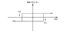
また、本発明の一態様では、前記力制御部は、前記第2の制御パラメーターセットを用いて力制御を行っている場合には、前記第1の方向への外力の大きさが第1の閾値を超えたと判断した時に、使用する前記制御パラメーターセットを前記第1の制御パラメーターセットに変更する前記変更処理を行い、前記第1の制御パラメーターセットを用いて力制御を行っている場合には、前記第2の方向への外力の大きさが第2の閾値を超えたと判断した時に、使用する前記制御パラメーターセットを前記第2の制御パラメーターセットに変更する前記変更処理を行ってもよい。 In the aspect of the invention, when the force control unit performs the force control using the second control parameter set, the magnitude of the external force in the first direction is the first value. When determining that the control parameter set to be used is changed to the first control parameter set when it is determined that the threshold value has been exceeded, and performing force control using the first control parameter set The change process of changing the control parameter set to be used to the second control parameter set may be performed when it is determined that the magnitude of the external force in the second direction has exceeded the second threshold value.
これにより、制御パラメーターセットの変更制御にヒステリシス特性を与えることができ、使用する制御パラメーターセットの変更が頻繁に起こることを回避すること等が可能になる。 As a result, it is possible to give a hysteresis characteristic to the change control of the control parameter set, and it is possible to avoid the frequent change of the control parameter set to be used.
また、本発明の一態様では、前記力制御部は、前記検出センサー値により表される外力の方向が前記第2の方向である場合には、前記第1の力制御を行って求めた第1の補正値と、前記第2の力制御を行って求めた第2の補正値とに対して重み付け処理を行って、第3の補正値を求め、求めた前記第3の補正値を出力してもよい。 In one aspect of the present invention, the force control unit obtains the first force control when the direction of the external force represented by the detection sensor value is the second direction. The correction value of 1 and the second correction value obtained by performing the second force control are weighted to obtain a third correction value, and the obtained third correction value is output. May be.
これにより、複数のデジタルフィルターのパラメーターを用いて、デジタルフィルター処理を行った時の出力値を求め、各出力値の重み付け加算を行うことにより補正値を求めて、非対称インピーダンス制御を実現すること等が可能になる。 As a result, using a plurality of digital filter parameters, the output value when digital filter processing is performed is obtained, the correction value is obtained by weighted addition of each output value, and asymmetric impedance control is realized, etc. Is possible.
また、本発明の一態様では、前記力制御部は、力制御における常微分方程式の解を前記補正値として求めるデジタルフィルター部を有してもよい。 In the aspect of the invention, the force control unit may include a digital filter unit that obtains a solution of an ordinary differential equation in force control as the correction value.
これにより、常微分方程式の解を求めるという力制御において必要な処理を、デジタルフィルターを用いて行うことが可能になるため、ハードウェアー化を容易にすること等が可能となる。 This makes it possible to perform processing necessary in force control for obtaining a solution of an ordinary differential equation using a digital filter, thereby facilitating hardware implementation.
また、本発明の一態様では、前記力制御部は、前記補正値を求める前記デジタルフィルター部の動作の安定度を判定し、前記デジタルフィルター部の前記動作が安定であると判定された場合に、力制御における前記常微分方程式の解を前記補正値として求めてもよい。 In one aspect of the present invention, the force control unit determines the stability of the operation of the digital filter unit for obtaining the correction value, and when the operation of the digital filter unit is determined to be stable. The solution of the ordinary differential equation in force control may be obtained as the correction value.
これにより、デジタルフィルターの安定性を判定すること等が可能になる。 This makes it possible to determine the stability of the digital filter.
また、本発明の一態様では、前記常微分方程式は、仮想質量項、仮想粘性項及び仮想弾性項を係数パラメーターとする運動方程式であってもよい。 In the aspect of the invention, the ordinary differential equation may be an equation of motion having a virtual mass term, a virtual viscosity term, and a virtual elasticity term as coefficient parameters.
これにより、運動方程式の解を求めること等が可能になる。 Thereby, it is possible to obtain a solution of the equation of motion.
また、本発明の他の態様は、前記ロボット制御装置と、前記目標値出力部から取得される前記目標値に基づいて、各部を動作させる前記ロボットと、を含むロボットシステムに関係する。 Another aspect of the present invention relates to a robot system including the robot control device and the robot that operates each unit based on the target value acquired from the target value output unit.
これにより、ロボット制御装置にとどまらず、本実施形態の処理を実行するロボットシステムを実現すること等が可能になる。 As a result, it is possible to realize a robot system that executes the processing of this embodiment as well as the robot control device.
また、本発明の他の態様は、力覚センサーから取得される検出センサー値に基づいて、ロボットの目標軌道の補正値として、力制御における常微分方程式の解を求め、前記検出センサー値により表される外力の方向が第1の方向である場合には、第1の力制御を行い、前記外力の方向が前記第1の方向と反対方向である第2の方向である場合には、前記第1の力制御と異なる第2の力制御を行い、前記目標軌道に対して前記補正値に基づく補正処理を行って目標値を求め、求めた前記目標値を出力し、前記目標値に基づいて、前記ロボットのフィードバック制御を行うことを特徴とするロボット制御方法に関係する。 According to another aspect of the present invention, a solution of an ordinary differential equation in force control is obtained as a correction value of a target trajectory of the robot based on a detection sensor value acquired from a force sensor, and is expressed by the detection sensor value. When the direction of the external force is the first direction, the first force control is performed, and when the direction of the external force is the second direction opposite to the first direction, A second force control different from the first force control is performed, a correction process based on the correction value is performed on the target trajectory to obtain a target value, the obtained target value is output, and based on the target value Thus, the present invention relates to a robot control method characterized by performing feedback control of the robot.
また、本発明の他の態様では、前記外力の方向が前記第1の方向である場合には、外力に対する変位変化量が第1の変位変化量となる力制御を、前記第1の力制御として行い、前記外力の方向が前記第2の方向である場合には、外力に対する前記変位変化量が前記第1の変位変化量とは異なる第2の変位変化量となる力制御を、前記第2の力制御として行うことを特徴とするロボット制御方法に関係する。 In another aspect of the present invention, when the direction of the external force is the first direction, the force control in which the displacement change amount with respect to the external force becomes the first displacement change amount is changed to the first force control. When the direction of the external force is the second direction, the force control is performed such that the displacement change amount with respect to the external force is a second displacement change amount different from the first displacement change amount. The present invention relates to a robot control method characterized in that the control is performed as a second force control.
また、本発明の他の態様は、力覚センサーを有するロボットの制御を行うロボット制御方法であって、前記力覚センサーに加えられた外力の方向に応じて、前記ロボットの変位の大きさが異なる力制御を行うことを特徴とするロボット制御方法に関係する。 According to another aspect of the present invention, there is provided a robot control method for controlling a robot having a force sensor, wherein the magnitude of displacement of the robot depends on a direction of an external force applied to the force sensor. The present invention relates to a robot control method characterized by performing different force control.
また、本発明の他の態様は、力覚センサーを有するロボットの制御を行うロボット制御方法であって、前記力覚センサーに第1の外力が加えられた場合の前記ロボットの変位の大きさと、前記力覚センサーに前記第1の外力と同じ大きさであって反対の方向の力である第2の外力が加えられた場合の前記ロボットの変位の大きさとが異なる力制御を行うことを特徴とするロボット制御方法に関係する。 According to another aspect of the present invention, there is provided a robot control method for controlling a robot having a force sensor, wherein the displacement of the robot when a first external force is applied to the force sensor; Force control is performed in which the magnitude of displacement of the robot is different when a second external force having the same magnitude as the first external force and in the opposite direction is applied to the force sensor. It relates to the robot control method.
以下、本実施形態について説明する。まず、本実施形態の概要を説明する。次に、第1の実施形態と第2の実施形態について、それぞれシステム構成例と詳細な処理について説明する。なお、以下に説明する本実施形態は、特許請求の範囲に記載された本発明の内容を不当に限定するものではない。また、本実施形態で説明される構成の全てが、本発明の必須構成要件であるとは限らない。 Hereinafter, this embodiment will be described. First, an outline of the present embodiment will be described. Next, a system configuration example and detailed processing will be described for the first embodiment and the second embodiment, respectively. In addition, this embodiment demonstrated below does not unduly limit the content of this invention described in the claim. In addition, all the configurations described in the present embodiment are not necessarily essential configuration requirements of the present invention.
1.概要
1.1 基本構成
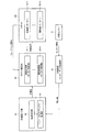
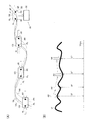
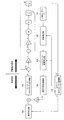
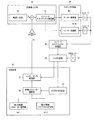
本実施形態のロボット制御装置(マニピュレーター制御装置)及びこれを含むロボットシステムの構成例を図1に示す。なお、本実施形態のロボット制御装置、ロボットシステムは図1の構成には限定されず、その一部の構成要素を省略したり、他の構成要素を追加したりするなどの種々の変形実施が可能である。
1. 1. Overview 1.1 Basic Configuration FIG. 1 shows a configuration example of a robot control device (manipulator control device) of the present embodiment and a robot system including the same. Note that the robot control apparatus and the robot system according to the present embodiment are not limited to the configuration shown in FIG. 1, and various modifications may be made such as omitting some of the components or adding other components. Is possible.
本実施形態のロボット制御装置は、力制御部20、目標値出力部60、ロボット制御部80を含む。また本実施形態のロボットシステムは、このロボット制御装置と、ロボット100(力覚センサー10)により構成される。
The robot control apparatus according to the present embodiment includes a
目標値出力部60は、ロボット(狭義にはマニピュレーター)のフィードバック制御の目標値を出力する。この目標値に基づいてロボット100のフィードバック制御が実現される。多関節ロボット等を例に取れば、この目標値は、ロボットの関節角情報などである。ロボットの関節角情報は、例えばロボットのアームのリンク機構における各関節の角度(ジョイント軸とジョイント軸のなす角度)を表す情報である。
The target
目標値出力部60は、軌道生成部62とインバースキネマティクス処理部64を含むことができる。軌道生成部62は、ロボットの軌道情報を出力する。軌道情報は、ロボットのエンドエフェクター部(エンドポイント)の位置情報(x,y,z)と、各座標軸回りでの回転角度情報(u,v,w)を含むことができる。インバースキネマティクス処理部64は、軌道生成部62からの軌道情報に基づいてインバースキネマティクス処理を行い、例えばロボットの関節角情報を目標値として出力する。インバースキネマティクス処理は、関節を有するロボットの動きを計算する処理であり、ロボットのエンドエフェクター部の位置姿勢などから関節角情報等を逆運動学により計算する処理である。
The target
力制御部20(狭義にはインピーダンス制御部)は、力覚センサー10からのセンサー情報に基づいて力制御(力覚制御)を行って、目標値の補正値を出力する。更に具体的には、力制御部20(インピーダンス制御部)は、力覚センサー10からのセンサー情報(力情報、モーメント情報)に基づいてインピーダンス制御(或いはコンプライアンス制御)を行う。力制御は、例えば、従来の位置制御に対して、力のフィードバックが加わった制御である。インピーダンス制御は、外力に対するエンドエフェクター部(手先)の変位の生じやすさ(機械インピーダンス)を、制御により望ましい状態にする手法である。具体的には、ロボットのエンドエフェクター部に質量と粘性係数と弾性要素が接続されるモデルにおいて、目標として設定した質量と粘性係数と弾性係数で物体に接触するようにする制御である。また力覚センサー10は、ロボット100が出している力に対する反力として受けている力や、モーメントを検出するセンサーである。この力覚センサー10は、通常、ロボット100のアームの手首部分に取り付けられ、検出された力やモーメントは、センサー情報として、各種の力制御(インピーダンス制御)に用いられる。
The force control unit 20 (impedance control unit in a narrow sense) performs force control (force control) based on sensor information from the
ロボット制御部80は、目標値出力部60から得られる目標値に基づいて、ロボット100のフィードバック制御を行う。具体的には、力制御部20からの補正値に基づく補正処理の結果出力された目標値に基づいて、ロボット100のフィードバック制御を行う。例えば目標値と、ロボット100からのフィードバック信号に基づいて、ロボット100のフィードバック制御を行う。例えばロボット制御部80は、複数の駆動制御部82―1〜82―N(狭義にはモーター制御部)を含み、ロボット100が有する駆動部102―1〜102―Nに対して、その制御信号を出力する。ここで駆動部102―1〜102―Nは、ロボット100の各関節を動かすための駆動機構であり、例えばモーター等により実現される。
The
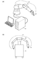
ここで、図2(A)に本実施形態のロボット制御装置を含むロボットシステムの例を示す。このロボットシステムは、制御装置300(情報処理装置)とロボット310(図1のロボット100)とを含む。制御装置300はロボット310の制御処理を行う。具体的には、動作シーケンス情報(シナリオ情報)に基づいてロボット310を動作させる制御を行う。ロボット310は、アーム320及びハンド(把持部)330を有する。そして、制御装置300からの動作指示にしたがって動作する。例えば、図示しないパレットに載せられたワークを把持したり、移動したりするなどの動作を行う。また、図示しない撮像装置で取得された撮像画像情報に基づいて、ロボットの姿勢やワークの位置などの情報が検出され、検出された情報が制御装置300に送られる。
Here, FIG. 2A shows an example of a robot system including the robot control apparatus of this embodiment. This robot system includes a control device 300 (information processing device) and a robot 310 (
本実施形態のロボット制御装置は、例えば図2(A)の制御装置300に設けられ、制御装置300のハードウェアーやプログラムによりロボット制御装置が実現される。そして、本実施形態のロボット制御装置によれば、制御装置300などの制御ハードウェアーに対する性能要求を低減できると共に、ロボット310を高い応答性で動作させることが可能になる。
The robot control apparatus according to the present embodiment is provided, for example, in the
また、図2(A)では、ロボット本体310(ロボット)と制御装置300(ロボット制御装置)とが別体に構成されているが、本実施形態のロボットは図2(A)の構成に限定されず、図2(B)のようにロボット本体310と制御装置300とが一体に構成されていてもよい。具体的には、図2(B)に示したように、ロボットはロボット本体310(アーム320及びハンド330を有する)及びロボット本体310を支えるベースユニット部を含み、当該ベースユニット部に制御装置300が格納される。図2(B)のロボットでは、ベースユニット部に車輪等が設けられ、ロボット全体が移動可能な構成となっている。なお、図2(A)は単腕型の例であるが、ロボットは図2(B)に示すように双腕型等の多腕型のロボットであってもよい。なお、ロボットの移動は人手で行われてもよいし、車輪を駆動するモーターを設け、当該モーターを制御装置300により制御することで行ってもよい。
In FIG. 2A, the robot body 310 (robot) and the control device 300 (robot control device) are configured separately, but the robot of this embodiment is limited to the configuration of FIG. 2A. Instead, the
1.2 力制御・インピーダンス制御
次に、力制御、インピーダンス制御(コンプライアンス制御)の概要について説明する。
1.2 Force Control / Impedance Control Next, an outline of force control and impedance control (compliance control) will be described.
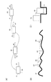
図3(A)は、ロボットの左のアームAL、右のアームARで物体OBを挟んで移動している様子を示している。例えば、位置制御だけでは、物体を落としたり、破壊したりしてしまうおそれがある。力制御によれば、柔軟な物体や脆い物体を、図3(A)のように両側から適切な力で挟んで移動させることが可能になる。 FIG. 3A shows a situation where the object OB is sandwiched between the left arm AL and the right arm AR of the robot. For example, the position control alone may cause an object to be dropped or destroyed. According to the force control, a flexible object or a fragile object can be moved while being sandwiched with appropriate force from both sides as shown in FIG.
また、力制御によれば、図3(B)に示すように、不確実性のある物体の表面SFをアームAM等でなぞることが可能になる。このような制御は位置制御だけでは実現不能である。また、力制御によれば、図3(C)に示すように、粗い位置決めの後に、探って位置合わせをして、物体OBを穴部HLにはめ込むことも可能になる。 Further, according to the force control, as shown in FIG. 3B, it is possible to trace the surface SF of an uncertain object with the arm AM or the like. Such control cannot be realized only by position control. Further, according to the force control, as shown in FIG. 3C, after rough positioning, it is possible to probe and align the object OB into the hole HL.
しかしながら、バネなどの実際の機械部品による力制御では、用途が限られるという問題がある。また、このような機械部品による力制御では、特性の動的な切り替えが困難である。 However, there is a problem that the application is limited in force control using actual mechanical parts such as a spring. In addition, in such force control using mechanical parts, it is difficult to dynamically switch characteristics.
一方、モーターのトルクを制御するトルク制御は簡単であるが、位置精度が悪くなるという問題がある。また、異常時に衝突などの問題が生じる。例えば図3(A)において、異常事態が起きて、物体OBを落としてしまった場合に、トルク制御では、釣合うべき反力が無くなるため、左右のアームAL、ARが衝突してしまうなどの問題が生じる。 On the other hand, torque control for controlling the torque of the motor is simple, but there is a problem that the positional accuracy is deteriorated. In addition, a problem such as a collision occurs when an abnormality occurs. For example, in FIG. 3A, when an abnormal situation occurs and the object OB is dropped, there is no reaction force to be balanced in the torque control, so the left and right arms AL and AR collide. Problems arise.
これに対して、インピーダンス制御(コンプライアンス制御)は、制御が複雑であるものの、汎用性や安全性が高いという利点がある。 On the other hand, although impedance control (compliance control) is complicated, there is an advantage that versatility and safety are high.
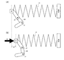
図4(A)、図4(B)は、インピーダンス制御の1つであるコンプライアンス制御を説明する図である。コンプライアンスはバネ定数の逆数を意味し、バネ定数が硬さを表すのに対して、コンプライアンスは柔らかさを意味する。ロボットと環境との間に相互作用が働くときに、機械的柔軟性であるコンプライアンスを与える制御をコンプライアンス制御と呼ぶ。 FIG. 4A and FIG. 4B are diagrams for explaining the compliance control which is one of the impedance controls. Compliance means the reciprocal of the spring constant, and the spring constant represents hardness, whereas compliance means softness. Control that provides compliance, which is mechanical flexibility, when interaction between the robot and the environment works is called compliance control.
例えば図4(A)では、ロボットのアームAMには力覚センサーSEが取り付けられている。このロボットのアームAMは、力覚センサーSEで得られたセンサー情報(力・トルク情報)に応じて姿勢が変わるようにプログラムされている。具体的には、図4(A)のA1に示す仮想的なバネが、あたかもアームAMの先端に取り付けられているかのようにロボットを制御する。 For example, in FIG. 4A, a force sensor SE is attached to the arm AM of the robot. The robot arm AM is programmed so that its posture changes according to sensor information (force / torque information) obtained by the force sensor SE. Specifically, the robot is controlled as if a virtual spring indicated by A1 in FIG. 4A is attached to the tip of the arm AM.
例えばA1に示すバネのバネ定数が100Kg/mであったとする。これを図4(B)のA2に示すように5Kgの力で押せば、A3に示すようにバネは5cmだけ縮む。逆に言えば、5cmだけ縮んでいれば、5Kgの力で押されているといえる。つまり、力情報と位置情報とが線形かつ対称に対応づけられている。 For example, it is assumed that the spring constant of the spring indicated by A1 is 100 kg / m. If this is pressed with a force of 5 kg as shown at A2 in FIG. 4B, the spring contracts by 5 cm as shown at A3. In other words, if it shrinks by 5 cm, it can be said that it is pushed with a force of 5 kg. That is, force information and position information are correlated linearly and symmetrically.
コンプライアンス制御では、このA1に示す仮想的なバネがアームAMの先端に取り付けられているかのような制御が行われる。具体的には、ロボットは、力覚センサーSEの入力に応答して動作し、A2に示す5Kgの加重に対して、A3に示すように5cmだけ後退するように制御され、力情報に対応して位置情報が変化するように制御される。 In the compliance control, control is performed as if the virtual spring indicated by A1 is attached to the tip of the arm AM. Specifically, the robot operates in response to the input of the force sensor SE, and is controlled to move back by 5 cm as shown in A3 with respect to the 5 kg weight shown in A2, corresponding to the force information. The position information is controlled to change.
このような単純なコンプライアンス制御では時間項を含まないが、時間項を含み、その2次の項までを考慮した制御が、インピーダンス制御である。具体的には、2次の項は質量項であり、1次の項は粘性項であり、インピーダンス制御のモデルは下式(1)に示すような運動方程式で表すことができる。 Such simple compliance control does not include a time term, but the control including the time term and considering the second order term is impedance control. Specifically, the second-order term is a mass term, the first-order term is a viscosity term, and the impedance control model can be expressed by an equation of motion as shown in the following equation (1).
![]()
![]()
上式(1)において、mは質量、μは粘性係数、kは弾性係数、fは力、xは目標位置からの変位である。またxの1次微分、2次微分は、各々、速度、加速度に対応する。インピーダンス制御では、上式(1)の特性をアームの先端であるエンドエフェクター部に持たせるための制御系を構成する。即ち上式(1)で表される仮想質量、仮想粘性係数、仮想弾性係数を、あたかもアームの先端が持っているかのように制御を行う。 In the above equation (1), m is mass, μ is a viscosity coefficient, k is an elastic coefficient, f is a force, and x is a displacement from a target position. The first and second derivatives of x correspond to speed and acceleration, respectively. In the impedance control, a control system for providing the end effector unit, which is the tip of the arm, with the characteristic of the above formula (1) is configured. That is, control is performed as if the tip of the arm has the virtual mass, virtual viscosity coefficient, and virtual elastic coefficient represented by the above equation (1).
このように、インピーダンス制御は、アームの先端の質量に粘性要素と弾性要素が各方向に接続されるモデルにおいて、目的として設定された粘性係数と弾性係数で物体に接触するようにする制御である。 As described above, impedance control is control that makes a contact with an object with a viscosity coefficient and an elastic coefficient set as an object in a model in which a viscous element and an elastic element are connected to the mass of the tip of the arm in each direction. .
例えば図5(A)に示すように、ロボットのアームAL、ARで物体OBをつかんで、軌道TRに沿って移動させる制御を考える。この場合に、軌道TRLは、物体OBの左側の内側に設定された点PLが通る軌道であり、インピーダンス制御を想定して決定された仮想的な左手の軌道である。また軌道TRRは、物体OBの右側の内側に設定された点PRが通る軌道であり、インピーダンス制御を想定して決定された仮想的な右手の軌道である。この場合に、アームALは、アームALの先端と点PLの距離差に応じた力が発生するように制御される。またアームARは、アームARの先端と点PRの距離差に応じた力が発生するように制御される。このようにすれば、物体OBを柔らかくつかみながら移動させるインピーダンス制御を実現できる。そして、インピーダンス制御では、図5(A)のB1に示すように物体OBが落下する事態が生じたとしても、アームAL、ARは、B2、B3に示すように、その先端が点PL、PRの位置で止まるように制御される。即ち、仮想的な軌道が衝突軌道でなければ、アームAL、ARが衝突するのを防止できる。 For example, as shown in FIG. 5A, let us consider a control in which an object OB is held by robot arms AL and AR and moved along a trajectory TR. In this case, the trajectory TRL is a trajectory through which the point PL set inside the left side of the object OB passes, and is a virtual left-hand trajectory determined on the assumption of impedance control. The trajectory TRR is a trajectory through which the point PR set inside the right side of the object OB passes, and is a virtual right-hand trajectory determined on the assumption of impedance control. In this case, the arm AL is controlled so that a force corresponding to the distance difference between the tip of the arm AL and the point PL is generated. The arm AR is controlled so that a force corresponding to the distance difference between the tip of the arm AR and the point PR is generated. In this way, it is possible to realize impedance control that moves the object OB while grasping it softly. In the impedance control, even if the situation where the object OB falls as shown by B1 in FIG. 5A occurs, the ends of the arms AL and AR are points PL and PR as shown by B2 and B3. It is controlled to stop at the position. That is, if the virtual trajectory is not a collision trajectory, it is possible to prevent the arms AL and AR from colliding.
また図5(B)のように、物体の表面SFをなぞるように制御する場合にも、インピーダンス制御では、アームAMの先端に対して、仮想的な軌道TRVAと先端との距離差DFに応じた力が働くように制御される。従って、アームAMを、力を加えながら表面SFをなぞるような制御が可能になる。 In addition, as shown in FIG. 5B, when the control is performed so that the surface SF of the object is traced, the impedance control is performed according to the distance difference DF between the virtual trajectory TRVA and the tip with respect to the tip of the arm AM. It is controlled so that the applied force works. Therefore, the arm AM can be controlled to trace the surface SF while applying a force.
これらの例は線形かつ対称なインピーダンス制御を行っている様子を示している。なお、ここで、線形インピーダンス制御とは、外力に対して変位が線形に変化するインピーダンス制御のことを指し、非線形インピーダンス制御とは、外力に対して変位が非線形に変化するインピーダンス制御の指す。さらに、対称インピーダンス制御とは、外力の方向に対して変位が対称であるインピーダンス制御のことを指し、非対称インピーダンス制御とは、外力の方向に対して変位が非対称であるインピーダンス制御のことを指す。 These examples show how linear and symmetric impedance control is performed. Here, linear impedance control refers to impedance control in which displacement changes linearly with respect to external force, and nonlinear impedance control refers to impedance control in which displacement changes nonlinearly with respect to external force. Furthermore, symmetric impedance control refers to impedance control in which displacement is symmetric with respect to the direction of external force, and asymmetric impedance control refers to impedance control in which displacement is asymmetric with respect to the direction of external force.
1.3 非対称インピーダンス制御
しかし、線形かつ対称なインピーダンス制御では、図6(A)〜図6(C)に示すような外力の向きに応じて異なる力制御が要求される事例には、十分に対応することができない。
1.3 Asymmetric Impedance Control However, linear and symmetric impedance control is sufficient for cases where different force control is required depending on the direction of external force as shown in FIGS. 6 (A) to 6 (C). I can't respond.
ここで、具体的に図6(A)〜図6(C)において求められるインピーダンス制御について説明する。 Here, the impedance control required in FIGS. 6A to 6C will be specifically described.
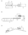
まず、図6(A)には、引き込み機構としてローラー部RLを持ち、加えてガイドローラー部GRLを有する装置に、ロボットのアームAMがワークWKを挿入する様子を示している。なお、ガイドローラー部GRLは、引き込み機構を持たないローラーであり、アームAMの先端には力覚センサーSEが設けられている。 First, FIG. 6A shows a state in which the arm W of the robot inserts the workpiece WK into an apparatus having the roller part RL as a pulling mechanism and additionally having a guide roller part GRL. The guide roller part GRL is a roller that does not have a pull-in mechanism, and a force sensor SE is provided at the tip of the arm AM.
本例では、ワークWKの先端がガイドローラー部GRLに接触している際には、力覚センサーSEが右向きの力を検出する。この時点では、右向きの外力に抵抗するような堅い力制御を行うことが望ましい。すなわち、外力に対する変位の変化量を小さくすべきである。 In this example, when the tip of the workpiece WK is in contact with the guide roller portion GRL, the force sensor SE detects a rightward force. At this point, it is desirable to perform hard force control that resists rightward external force. That is, the amount of change in displacement with respect to external force should be reduced.
そして、ワークWKがアームAMに押されて右に移動し、ワークWKの先端がローラー部RLに接触した際には、力覚センサーが左向きの力を検出する。ローラー部RLがワークWKを引き込むためである。本例では、ワークWKを装置内に押し込むことが目的であるため、これ以降は左向きの外力に倣って動くような柔らかい力制御を行うべきである。言い換えれば、外力に対する変位の変化量を大きくすべきである。 When the work WK is pushed by the arm AM and moves to the right, and the tip of the work WK comes into contact with the roller portion RL, the force sensor detects a leftward force. This is because the roller unit RL pulls the workpiece WK. In this example, since the purpose is to push the workpiece WK into the apparatus, after that, soft force control should be performed so as to move following the leftward external force. In other words, the amount of change in displacement with respect to external force should be increased.
図6(B)の例も図6(A)の例と同様に、ガイドローラー部GRL上でワークWKを移動させている場合には、右向きの外力に抵抗するような力制御を行い、ベルトコンベアー部BCにワークWKが接触した時点では、左向きの外力に対して従順な力制御を行うべきである。 6B, similarly to the example of FIG. 6A, when the workpiece WK is moved on the guide roller portion GRL, force control is performed so as to resist the rightward external force, When the workpiece WK comes into contact with the conveyor part BC, compliant force control should be performed with respect to the leftward external force.
さらに、図6(C)の場合も図6(A)及び図6(B)の例と同様であり、坂を上っている時には外力に対する変位変化量が小さくなる制御を行い、坂を下っている時には外力に対する変位変化量が大きくなる制御を行うことが望ましい。 Further, the case of FIG. 6C is the same as the example of FIGS. 6A and 6B, and when the hill is climbed, the displacement change amount with respect to the external force is controlled to be smaller, and the hill is lowered. It is desirable to perform control that increases the amount of change in displacement with respect to external force.
次に、各力制御における外力と変位の関係という観点から、対称インピーダンス制御と非対称インピーダンス制御の違いについて、図7(A)〜図7(D)を用いて説明する。なお、例えば、図7(A)〜図7(D)を、図6(A)の例に当てはめて考える場合には、ワークWKを押し込む時に受ける右方向の力を負の外力として表し、ワークWKがローラー部RLにより引っ張られる時に受ける左方向の力を正の外力として表すものとする。 Next, from the viewpoint of the relationship between external force and displacement in each force control, the difference between symmetric impedance control and asymmetric impedance control will be described with reference to FIGS. For example, in the case where FIGS. 7A to 7D are applied to the example of FIG. 6A, the rightward force received when the work WK is pushed in is expressed as a negative external force. The leftward force received when WK is pulled by the roller portion RL is expressed as a positive external force.
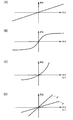
まず、図7(A)には、線形かつ対称なインピーダンス制御の例を示す。すなわち、図7(A)のグラフは、外力が大きくなるほど、変位も比例して大きくなる様子を示している。前述した図5(A)、図5(B)における外力と変位にはこのような関係が成り立っている。 First, FIG. 7A shows an example of linear and symmetrical impedance control. That is, the graph in FIG. 7A shows that the displacement increases proportionally as the external force increases. Such a relationship is established between the external force and displacement in FIGS. 5A and 5B described above.
次に、図7(B)には所定の閾値以上外力が大きくなった場合には、変位が大きくなりにくくする非線形インピーダンス制御の例を示す。 Next, FIG. 7B shows an example of non-linear impedance control that makes it difficult for displacement to increase when an external force increases beyond a predetermined threshold.
これらの図7(A)と図7(B)に示す対称インピーダンス制御では、外力の方向が変わったとしても、外力と変位の関係は変化しない。つまり、図7(A)と図7(B)では、外力の方向が第1の方向(右方向)であろうが、第1の方向と逆方向である第2の方向(左方向)であろうが、外力の大きさが同じならば、それに対する変位の大きさ(絶対値)も同じである。 In the symmetrical impedance control shown in FIGS. 7A and 7B, even if the direction of the external force changes, the relationship between the external force and the displacement does not change. That is, in FIGS. 7A and 7B, the direction of the external force will be the first direction (right direction), but in the second direction (left direction) opposite to the first direction. However, if the magnitude of the external force is the same, the magnitude of the displacement (absolute value) is the same.
次に、図6(A)のような事例において求められる外力と変位の理想的な関係とそれを実現する力制御について説明する。なお、ここでは説明を分かりやすくするため、コンプライアンス制御についてのみ説明を行うが、コンプライアンス制御に限定されず、インピーダンス制御に対しても適用されるものである。 Next, an ideal relationship between external force and displacement required in the case as shown in FIG. 6A and force control for realizing the relationship will be described. In order to make the explanation easy to understand, only the compliance control will be described. However, the present invention is not limited to the compliance control, and is applied to the impedance control.
まず結論から先に述べると、後述する第1の実施形態及び第2の実施形態では、図6(A)のような事例において求められる力制御として、力覚センサーに加えられた外力の方向と、外力が加えられた時のロボットの変位の大きさとの関係が非対称になる力制御を行う。すなわち、力覚センサーに加えられた外力の方向に応じて、ロボットの変位の大きさが異なる力制御を行う。 First, from the conclusion, in the first embodiment and the second embodiment described later, the direction of the external force applied to the force sensor as the force control required in the case shown in FIG. Then, force control is performed in which the relationship with the magnitude of the displacement of the robot when an external force is applied becomes asymmetric. That is, force control is performed in which the magnitude of the displacement of the robot is different according to the direction of the external force applied to the force sensor.
ここでは具体的に、式(1)におけるコンプライアンス項(弾性項)をxの関数g(x)とした運動方程式である下式(2)を考える。 Here, specifically, the following equation (2), which is an equation of motion in which the compliance term (elastic term) in equation (1) is a function g (x) of x, is considered.
![]()
![]()
例えば、式(2)におけるg(x)が図7(C)の曲線のような形をしていれば、図6(A)のワークWKを押し込む時に受ける右方向の外力には硬く、ワークWKが引っ張られる時に受ける左方向の外力には柔らかい構造を実現しているように見える。このようなインピーダンス制御を行えば、外力の方向に対する非対称性を獲得できる。 For example, if g (x) in equation (2) has a shape like the curve in FIG. 7C, the external force applied in the right direction when the work WK in FIG. It seems that a soft structure is realized in the leftward external force received when the WK is pulled. By performing such impedance control, asymmetry with respect to the direction of the external force can be obtained.
しかし正確に言えば、このg(x)は変位xの関数であり、外力の方向に依存して、制御パラメーターが変化するわけではない。つまり、外力の方向が変化していない範囲においても、応答特性が変化してしまっており、図6(A)で求められる応答特性とは微妙に異なる。実際に欲しいのは、例えば、以下に示す図7(D)のような特性である。 However, to be exact, this g (x) is a function of the displacement x, and the control parameter does not change depending on the direction of the external force. That is, even in the range where the direction of the external force does not change, the response characteristic has changed, which is slightly different from the response characteristic obtained in FIG. What is actually desired is, for example, the characteristics shown in FIG.
図7(D)に示すような非対称インピーダンス制御では、第1の方向に対する外力と変位の関係はg1の直線のようになり、第1の方向と反対方向である第2の方向に対する外力と変位の関係はg2の直線のようになる。すなわち、図7(A)や図7(B)に示す対称インピーダンス制御と違い、外力の方向が第1の方向である時と、外力の方向が第2の方向である時とで、外力に対する変位変化量(つまり、g1とg2の直線の傾き)が異なる。言い換えれば、外力の方向に応じて、外力と変位の関係が異なる。 In the asymmetric impedance control as shown in FIG. 7D, the relationship between the external force and the displacement in the first direction is a straight line g1, and the external force and the displacement in the second direction that is opposite to the first direction. Is a straight line of g2. That is, unlike the symmetrical impedance control shown in FIGS. 7A and 7B, when the direction of the external force is the first direction and when the direction of the external force is the second direction, The displacement change amount (that is, the slope of the straight line between g1 and g2) is different. In other words, the relationship between the external force and the displacement differs depending on the direction of the external force.
具体的には、図6(A)のワークWKを押し込む時に受ける右方向の外力に対してはg1の曲線に従い、外力が大きくなっても変位が変化しにくい硬い力制御を行い、ワークWKが引っ張られる時に受ける左方向の外力には対してはg2の曲線に従い、小さい外力であっても変位が変化しやすい柔らかい力制御を実現する。 Specifically, for the external force in the right direction that is received when the workpiece WK in FIG. 6A is pushed in, according to the curve of g1, a hard force control that hardly changes the displacement even when the external force increases is performed. According to the curve of g2 for the external force in the left direction received when pulled, soft force control is realized in which the displacement easily changes even with a small external force.
このように、本出願人は、例えば図6(A)〜図6(C)のような事例に対して、図7(D)に示すような非対称インピーダンス制御を行うロボット制御装置等を提案する。 Thus, the present applicant proposes, for example, a robot control device that performs asymmetric impedance control as shown in FIG. 7D for the cases as shown in FIGS. 6A to 6C. .
1.4 制御系の構成
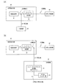
さて、ここで、力覚フィードバックを含まない場合の制御系の基本構成例を図8に示す。
1.4 Configuration of Control System Now, FIG. 8 shows an example of the basic configuration of the control system when force feedback is not included.
軌道生成部562は、軌道情報p(xyzuvw)を生成してインバースキネマティクス処理部564に出力する。ここで軌道情報pは、例えばアームの先端(エンドエフェクター部)の位置情報(xyz)と各軸回りの回転情報(uvw)を含む。そしてインバースキネマティクス処理部564は、この軌道情報pに基づいてインバースキネマティクス処理を行って、目標値である各関節の関節角θを生成して出力する。そして、この関節角θに基づいて、モーター制御を行うことで、ロボットのアームの動作制御が行われる。この場合に図8のモーター(M)の制御は、公知のPID制御により実現されている。このPID制御は公知の技術であるため、ここでは詳細な説明を省略する。
The
図8において、軌道生成部562とインバースキネマティクス処理部564とにより目標値出力部が構成される。この目標値出力部の処理は、ロボットの全体的な処理になる。一方、後段のモーター制御は、関節毎の制御になる。
In FIG. 8, the
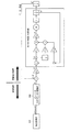
図9に、力覚フィードバックを含む場合の制御系の基本構成例を示す。図9では、図8に対して、更に、力覚センサー510と、姿勢補正部532と、ハンド・ツール自重補正部534と、運動方程式処理部536と、フォワードキネマティクス処理部540が設けられている。
FIG. 9 shows a basic configuration example of the control system in the case of including force feedback. 9 further includes a
図9では、力覚センサー510からのセンサー情報を受けて、姿勢補正部532がセンサーの姿勢補正を行い、ハンド・ツール自重補正部534がハンド・ツール自重補正を行う。そして、運動方程式処理部536が、前述の式(1)に示すような運動方程式の解を求める処理を行い、補正値Δpを出力する。この補正値Δpにより軌道情報pが補正されることで、目標値である関節角θの補正処理が行われる。またフォワードキネマティクス処理部540は、フォワードキネマティクス処理を行って、ロボットの軌道情報p’を求めて軌道生成部562にフィードバックする。また姿勢補正部532、ハンド・ツール自重補正部534に対して姿勢を特定するための情報を出力する。なお、ロボットの軌道情報p’の軌道生成部562へのフィードバックは、p’に基づいた軌道の修正処理等を行うためのものであり、当該修正処理等を行わないのであれば、フィードバックは必ずしも必要ない。
In FIG. 9, in response to sensor information from the
ハンド・ツール自重補正部534では、ハンド・ツール自重補正が行われ、姿勢補正部532では姿勢補正が行われる。ここでハンド・ツール自重補正は、ロボットのハンドの自重や、ハンドがつかむツールの自重による影響を、力覚センサー10からのセンサー情報(力情報)から相殺するための補正処理である。また姿勢補正は、力覚センサー10の姿勢による影響を、センサー情報(力情報)から相殺するための補正処理である。これらのハンド・ツール自重補正及び姿勢補正は、例えば下式(3)のように表すことができる。
The hand / tool self-

上式(3)において、Fx,Fy,Fz、Fu,Fv,Fwは力覚センサー10からのセンサー情報である力情報、トルク情報である。またBx,By,Bz、Bu,Bv,Bwはバイアス項である。そして、補正後のセンサー情報(力情報、トルク情報)であるfx,fy,fz、fu,fv,fwが運動方程式処理部536に入力される。なお、データには固定値があるため、実質的な補正係数は6×7=42個となる。これらのハンド・ツール自重補正及び姿勢補正は公知の補正処理であるため、詳しい説明は省略する。
In the above equation (3), Fx, Fy, Fz, Fu, Fv, and Fw are force information and torque information that are sensor information from the
1.5 デジタルフィルター処理
図9の運動方程式処理部536では運動方程式(広義には常微分方程式)の解を求める必要がある。従来、運動方程式の解を求めるにはNewton法やRunge−Kutta法等が用いられていた。しかし、これらの手法はハードウェアー化に適さず、安定性の判定も難しい。さらに応答性の切り替えに対応することが困難であるという問題もある。
1.5 Digital Filter Processing The equation of
そこで本出願人は、上述の3つの問題に対応するために、常微分方程式を解く手法としてデジタルフィルターを用いる。 Therefore, the present applicant uses a digital filter as a technique for solving an ordinary differential equation in order to deal with the above three problems.
1.5.1 運動方程式のデジタルフィルターを用いた解法
運動方程式は上述した式(1)の形で表される。運動方程式は線形常微分方程式であるため、インパルス入力に対する解であるインパルスレスポンスが求められれば、インパルスレスポンスと外力項との畳み込みにより、任意の外力項に対する解を得ることができる。
1.5.1 Solution of equation of motion using digital filter The equation of motion is expressed in the form of equation (1) described above. Since the equation of motion is a linear ordinary differential equation, if an impulse response that is a solution to the impulse input is obtained, a solution for an arbitrary external force term can be obtained by convolution of the impulse response and the external force term.
ここで、運動方程式の解を求めるというステップを、力覚センサーのセンサー情報の入力に対して解(例えば位置情報)を出力するフィルターであると捉えるならば、上式(1)の形から、2極のアナログフィルターとして考えることができる。 Here, if the step of obtaining the solution of the equation of motion is regarded as a filter that outputs a solution (for example, position information) in response to input of sensor information of the force sensor, from the form of the above equation (1), It can be thought of as a two-pole analog filter.
つまり、運動方程式の解はアナログフィルターの出力として求めることができるのであるから、当該アナログフィルターをデジタルフィルター化することで、デジタルフィルターを用いて運動方程式を解くことが可能になる。 That is, since the solution of the equation of motion can be obtained as the output of the analog filter, the equation of motion can be solved using the digital filter by converting the analog filter into a digital filter.
アナログフィルターのデジタルフィルター化の手法は種々知られているが、例えばImpulse Invariance法を用いればよい。これは、アナログフィルターのインパルスレスポンスを離散時間Tでサンプルした値と同じインパルスレスポンスを与えるデジタルフィルターを考える手法である。Impulse Invariance法については公知の手法であるため詳細な説明は省略する。 Various methods for converting an analog filter into a digital filter are known. For example, an impulse invariance method may be used. This is a technique for considering a digital filter that gives the same impulse response as the value obtained by sampling the impulse response of an analog filter at a discrete time T. Since the Impulse Invariance method is a known method, detailed description thereof is omitted.
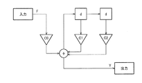
以上の結果、常微分方程式の解はデジタルフィルターの出力として求めることが可能になる。運動方程式であれば、図10に示したように2極のデジタルフィルターとなる。図10において、dは1サンプル分の遅延であり、C0、C1、C2はデジタルフィルターの係数(デジタルフィルターパラメーター)である。なお、図10のデジタルフィルターの入力値Fと出力値Ynの関係は式(4)のように表すことができる。 As a result, the solution of the ordinary differential equation can be obtained as the output of the digital filter. If it is an equation of motion, it will become a bipolar digital filter as shown in FIG. In FIG. 10, d is a delay for one sample, and C 0 , C 1 , and C 2 are digital filter coefficients (digital filter parameters). The relationship between the input value F and an output value Y n of the digital filter of FIG. 10 can be expressed by the equation (4).
![]()
![]()
デジタルフィルターによる処理であれば、ハードウェアー化は容易であるし、後述するように安定性の判定も容易である。また、デジタルフィルターの係数を切り替えれば、特性(柔らかく動かすか硬く動かすか等)を切り替えることもできるし、フィルター駆動周波数を切り替えて解の応答性を切り替えることもできる。 If the processing is performed using a digital filter, it is easy to implement hardware, and it is also easy to determine stability as described later. In addition, by switching the coefficient of the digital filter, it is possible to switch the characteristics (whether it is moved softly or hardly), and the response of the solution can be switched by switching the filter driving frequency.
1.5.2 デジタルフィルターの安定度判定
インピーダンス制御においては、運動方程式の質量項(m)、粘性項(μ)及び弾性項(k)の設定次第では、安定でない系ができてしまう可能性がある。極端な例で言えば、ロボットに一度力を加えたら、その後一切触れていないにもかかわらずロボットの振動が継続するような、発振する系にもなりうるということである。そのような安定性(安定度)の低い系は実用上好ましくないため、運動方程式に関する系の安定性を判定し、安定でない場合には何らかの対処をする必要がある。
1.5.2 Stability judgment of digital filter In impedance control, depending on the setting of mass term (m), viscosity term (μ), and elasticity term (k) in the equation of motion, there is a possibility that an unstable system may be formed. There is. In an extreme example, once a force is applied to a robot, it can be an oscillating system where the robot continues to vibrate even though it has not been touched at all. Such a system with low stability (stability) is not preferable in practice, and therefore it is necessary to determine the stability of the system related to the equation of motion, and to take some measures if it is not stable.
しかし、上述のNewton法やRunge−Kutta法等では、運動方程式の解を求めることはできても、安定性の判定は行えない。そのため、解を求める処理とは別に安定性を判定する処理が必要となるが、一般的に安定性の判定処理は容易でないことが知られている。 However, with the Newton method and the Runge-Kutta method described above, it is possible to determine the solution of the equation of motion, but it is not possible to determine the stability. Therefore, a process for determining stability is required separately from the process for obtaining a solution, but it is generally known that the process for determining stability is not easy.
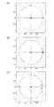
本実施形態の手法では、運動方程式を、デジタルフィルターを用いて処理するため、運動方程式に関する系の安定性の判定とは、対応するデジタルフィルターの安定性の判定に他ならない。デジタルフィルターの安定性の判定は、容易に行うことができ、極が単位円の中にあるか否かを判定すればよい。 In the method of the present embodiment, since the equation of motion is processed using a digital filter, the determination of the stability of the system related to the equation of motion is nothing but the determination of the stability of the corresponding digital filter. The stability of the digital filter can be easily determined, and it is only necessary to determine whether the pole is in the unit circle.
具体例を図11(A)〜図11(C)に示す。これらはどれも極が単位円の中に収まっている例であるが、極が単位円の外にある場合には安定でないと判定する。また、図11(C)のようにある程度、単位円の円周上から内側に離れた位置に極がある場合には、特に問題はない。しかし、図11(A)のように単位円にかなり近い位置に極(なお、図11(A)は重根ではなく限りなく近い位置に2つの極がある例である)がある場合には、注意が必要である。なぜなら、デジタルフィルターの実装手法によっては、設計値に対して誤差が生ずるおそれがあるからである。当該誤差が極の位置を単位円の外側方向に移動させる要因となった場合、図11(A)のような安定性に余裕のないデジタルフィルターは、設計上安定であるにもかかわらず、実装時には安定でない動作をする可能性があるため、何らかの対処が必要となる。 Specific examples are shown in FIGS. 11A to 11C. These are all examples in which the pole is within the unit circle, but if the pole is outside the unit circle, it is determined that the pole is not stable. In addition, there is no particular problem when there is a pole at a position away from the circumference of the unit circle to some extent as shown in FIG. However, in the case where there is a pole at a position quite close to the unit circle as shown in FIG. 11A (note that FIG. 11A is an example in which there are two poles in a position as close as possible, not a multiple root), Caution must be taken. This is because an error may occur with respect to the design value depending on the digital filter mounting method. When the error causes the position of the pole to move in the direction outside the unit circle, a digital filter with no margin for stability as shown in FIG. Since some operations may be unstable at times, some countermeasure is required.
1.5.3 デジタルフィルターを用いた場合の構成例
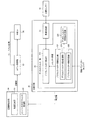
図12にデジタルフィルターを用いて運動方程式の解を求める場合の、ロボット制御装置及びそれを含むロボットシステム及びセンサー情報装置の構成例を示す。なお本実施形態のロボット制御装置、ロボットシステム及びセンサー情報装置は図12の構成には限定されず、その一部の構成要素を省略したり、他の構成要素を追加したりするなどの種々の変形実施が可能である。
1.5.3 Configuration Example Using Digital Filter FIG. 12 shows a configuration example of a robot control device, a robot system including the same, and a sensor information device in the case of obtaining a solution of an equation of motion using the digital filter. Note that the robot control device, the robot system, and the sensor information device of the present embodiment are not limited to the configuration shown in FIG. 12, and various components such as omitting some of the components or adding other components. Variations are possible.
力覚センサー10、目標値出力部60、ロボット制御部80及びロボット100については図1と同様であるため、詳細な説明は省略する。
The
力制御部20は、デジタルフィルター部22を含む。デジタルフィルター部22は、力覚センサーからのセンサー情報(センサー情報に対して補正処理や帯域制限処理が施された情報も含む)に対してデジタルフィルター処理を行って、出力値を補正値として目標値出力部60に出力する。また、力制御部20はセンサー情報に対して帯域制限処理を行う帯域制限部25を含んでもよい。
The
デジタルフィルター部22は、デジタルフィルター演算部221と、デジタルフィルター係数出力部222と、デジタルフィルター安定度判定部223を含む。デジタルフィルター演算部221は、センサー情報とデジタルフィルター係数に基づいて、デジタルフィルター処理を行って運動方程式の解を求める。デジタルフィルター係数出力部222は、運動方程式の係数パラメーター(質量項m、粘性項μ、弾性項k及び駆動周期T)に基づいて、デジタルフィルター係数を求め、デジタルフィルター演算部221とデジタルフィルター安定度判定部223に出力する。デジタルフィルター安定度判定部223は、デジタルフィルター係数に基づいて、当該デジタルフィルターの安定性の判定を行う。
The
デジタルフィルター係数出力部222は、デジタルフィルター係数記憶部224と、デジタルフィルター係数変換部225を含んでもよい。デジタルフィルター係数変換部225は、運動方程式の係数パラメーターをデジタルフィルター係数に変換する。デジタルフィルター係数記憶部224は、変換されたデジタルフィルター係数を記憶する。デジタルフィルター係数記憶部224に複数のデジタルフィルター係数を記憶しておけば、出力するデジタルフィルター係数を切り替えることで、ロボットの動作特性や、解の応答性を切り替えることが可能になる。
The digital filter
以下、図12の構成を基本とし、図7(D)のような非対称インピーダンス制御を実現する第1の実施形態と第2の実施形態について説明する。第1の実施形態は、本発明の基本形であり、外力の方向に応じて使用する制御フィルターのパラメーターを切り替えて、非対称インピーダンス制御を行う例である。そして、第2の実施形態は、所定の制御パラメーター変更指示等があった場合に、制御パラメーターを変更して、非対称インピーダンス制御を行う例である。 Hereinafter, a first embodiment and a second embodiment that realize the asymmetric impedance control as shown in FIG. 7D based on the configuration of FIG. 12 will be described. The first embodiment is a basic form of the present invention, and is an example in which asymmetric impedance control is performed by switching parameters of a control filter used according to the direction of external force. The second embodiment is an example of performing asymmetric impedance control by changing a control parameter when a predetermined control parameter change instruction or the like is given.
2.第1の実施形態
2.1 構成
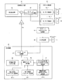
図13に第1の実施形態に係るロボット制御装置の構成例を示す。
2. First Embodiment 2.1 Configuration FIG. 13 shows a configuration example of a robot control apparatus according to the first embodiment.
力覚センサー10、目標値出力部60(軌道生成部62、インバースキネマティクス処理部64)、ロボット制御部80(モーター制御部82−1〜モーター制御部82−N)等については図1と同様であるため詳細な説明は省略する。また、入力補正部30は検出センサー値(センサー情報)に対して補正処理を行うもので、例えば図9の姿勢補正部532やハンド・ツール自重補正部534等を含んでもよい。フォワードキネマティクス処理部40は、図9のフォワードキネマティクス処理部540に対応し、フォワードキネマティクス処理の結果を入力補正部30に出力するとともに、必要に応じて軌道生成部62にも出力してもよい。
The
また、ロボット制御装置の力制御部20は、インピーダンス処理部21と、第1の制御パラメーター記憶部24−1と、第2の制御パラメーター記憶部24−2と、制御パラメーター選択部26と、外力方向判定部27と、を含む。なお、本実施形態の力制御部20は図13の構成には限定されず、その一部の構成要素を省略したり、他の構成要素を追加したりするなどの種々の変形実施が可能である。
In addition, the
また、図13のインピーダンス処理部21は、図12のデジタルフィルター演算部221に対応し、動作も同様のため、説明を省略する。さらに、図13の第1の制御パラメーター記憶部24−1と第2の制御パラメーター記憶部24−2は、図12のデジタルフィルター係数記憶部224に対応し、図13の制御パラメーター選択部26は、図12のデジタルフィルター係数変換部225に対応する。
The
第1の制御パラメーター記憶部24−1と第2の制御パラメーター記憶部24−2は、それぞれ異なる制御パラメーターを記憶する。ここで、制御パラメーターとは、後述する運動方程式の係数パラメーターであっても良いし、デジタルフィルターのパラメーターであってもよい。さらに、制御パラメーターとして、オフセットパラメーターを記憶してもよい。ここで、オフセットパラメーターとは、外力が0である場合の仮想変位のことをいう。制御パラメーター記憶部の機能は、RAM等のメモリーやHDD(ハードディスクドライブ)などにより実現でき、実際には一つのメモリー等により構成されていても良いし、複数のメモリー等により構成されていても良い。 The first control parameter storage unit 24-1 and the second control parameter storage unit 24-2 store different control parameters. Here, the control parameter may be a coefficient parameter of an equation of motion described later, or may be a parameter of a digital filter. Further, an offset parameter may be stored as a control parameter. Here, the offset parameter refers to a virtual displacement when the external force is zero. The function of the control parameter storage unit can be realized by a memory such as a RAM, an HDD (hard disk drive), etc., and may actually be constituted by a single memory or a plurality of memories. .
次に、外力方向判定部27は、入力補正部30から取得される姿勢補正後の検出センサー値(外力)に基づいて、外力の方向を判定し、制御パラメーター選択部26に外力の方向を通知する。
Next, the external force
そして、制御パラメーター選択部26は、外力方向判定部27により判定された外力の方向に基づいて、第1の制御パラメーター記憶部24−1と第2の制御パラメーター記憶部24−2とに記憶された制御パラメーターの中から、使用する制御パラメーターを選択し、インピーダンス処理部21に出力する。また、第1の制御パラメーター記憶部24−1と第2の制御パラメーター記憶部24−2とに記憶された制御パラメーターが、運動方程式の係数パラメーターである場合には、係数パラメーターをデジタルフィルターのパラメーターへ変換する処理等を行う。
The control
また、本実施形態においては、図10に示したデジタルフィルターと同様の構成からなるデジタルフィルターを用いることができる。 In the present embodiment, a digital filter having the same configuration as the digital filter shown in FIG. 10 can be used.
図10に示したデジタルフィルターによる処理であれば、ハードウェアー化は容易であるし、安定性の判定も容易である。 If the processing by the digital filter shown in FIG. 10 is performed, hardware implementation is easy, and stability determination is also easy.
2.2 詳細な処理
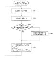
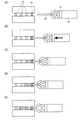
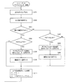
次に図14のフローチャートを用いて、本実施形態における力制御部が行うデジタルフィルター処理の流れを説明する。また、図6(A)の事例における非対称インピーダンス制御の各動作ステップを説明する具体例を図15(A)〜図15(E)に示す。以下では、具体例を交えて、フローチャートの説明を行う。
2.2 Detailed Processing Next, the flow of the digital filter processing performed by the force control unit in the present embodiment will be described using the flowchart of FIG. Moreover, the specific example explaining each operation | movement step of asymmetrical impedance control in the example of FIG. 6 (A) is shown to FIG. 15 (A)-FIG.15 (E). Hereinafter, the flowchart will be described with a specific example.
デジタルフィルター処理の流れとしては、まず、出力タイミングを待ち(S101)、出力タイミングとなった時に、入力補正部30から姿勢補正後の外力(外力値)Fを取得する(S102)。 As a flow of the digital filter processing, first, an output timing is waited (S101), and when the output timing is reached, an external force (external force value) F after posture correction is acquired from the input correction unit 30 (S102).
図15(A)〜図15(E)に示す具体例では、図15(A)の時点では、ロボットのアームAMが把持するワークWKの先端がガイドローラー部GRLに触れておらず、外力は検出されないが(検出センサー値が0となる)、図15(B)の時点でガイドローラー部GRLから受ける右向きの外力が検出される。なお、検出センサー値が0である場合でも、以下の処理を行っても良い。 In the specific examples shown in FIGS. 15A to 15E, at the time of FIG. 15A, the tip of the work WK gripped by the robot arm AM is not touching the guide roller portion GRL, and the external force is Although not detected (the detection sensor value becomes 0), the rightward external force received from the guide roller unit GRL at the time of FIG. 15B is detected. Even when the detection sensor value is 0, the following processing may be performed.
次に、一つ前の外力値と現在の外力値の符号が同じか否かを判定する(S103)。ここで、外力値の符号とは、外力の方向のことを指す。例えば、外力値の符号が「−」である場合には、外力の方向が図の右方向(第1の方向)であり、外力値の符号が「+」である場合には、外力の方向が図の左方向(第2の方向)であるとする。すなわち、ステップS103では、外力の方向に変化があったか否かを判定する。 Next, it is determined whether or not the sign of the previous external force value and the current external force value is the same (S103). Here, the sign of the external force value refers to the direction of the external force. For example, when the sign of the external force value is “−”, the direction of the external force is the right direction (first direction) in the figure, and when the sign of the external force value is “+”, the direction of the external force. Is the left direction (second direction) in the figure. That is, in step S103, it is determined whether or not the direction of the external force has changed.
一つ前の外力値と現在の外力値の符号が異なると判定した場合には、外力の方向が変化したと判断し、現在の符号(外力の方向)に対応する制御パラメーターを設定し(S104)、ステップS105の処理を行う。 If it is determined that the sign of the previous external force value and the current external force value is different, it is determined that the direction of the external force has changed, and a control parameter corresponding to the current sign (external force direction) is set (S104). ), The process of step S105 is performed.
例えば、図15(B)における外力の方向は右方向であり、外力値の符号は「−」である。一方、図15(C)の状態では、ローラー部RLがワークWKを引き込むため、外力の方向は左方向であり、外力値の符号が「+」となる。よって、図15(B)の状態と図15(C)の状態では外力値の符号が異なる。そのため、制御パラメーター選択部26は、外力の方向が変化したと判断し、制御パラメーターを変更する。なお、本例では、初期状態では第1の制御パラメーター記憶部24−1に記憶される第1の制御パラメーターが設定されているとし、外力の方向が変化した時点で、第2の制御パラメーター記憶部24−2に記憶される第2の制御パラメーターへと使用する制御パラメーターを変更する。
For example, the direction of the external force in FIG. 15B is the right direction, and the sign of the external force value is “−”. On the other hand, in the state of FIG. 15C, since the roller portion RL pulls the work WK, the direction of the external force is leftward, and the sign of the external force value is “+”. Therefore, the sign of the external force value is different between the state of FIG. 15B and the state of FIG. Therefore, the control
一方、一つ前の外力値と現在の外力値の符号が同じであると判定した場合には、外力の方向に変化がみられないと判断し、現在設定されている制御パラメーターを変更せずに、ステップS105の処理を行う。 On the other hand, if it is determined that the sign of the previous external force value and the current external force value is the same, it is determined that there is no change in the direction of the external force, and the currently set control parameter is not changed. Then, the process of step S105 is performed.
例えば、図15(C)における外力の方向は左方向であり、外力値の符号は「+」である。さらに、図15(D)や図15(E)の状態でも、外力の方向は左方向であり、外力値の符号は「+」のままであるため、図15(C)の状態から図15(E)の状態まで外力値の符号に変化はない。そのため、ここでは使用する制御パラメーターを変更しない。 For example, the direction of the external force in FIG. 15C is the left direction, and the sign of the external force value is “+”. Further, even in the states of FIG. 15D and FIG. 15E, the direction of the external force is leftward, and the sign of the external force value remains “+”. Therefore, from the state of FIG. There is no change in the sign of the external force value until the state of (E). Therefore, the control parameters used here are not changed.
そして、設定された制御パラメーターに基づいて、式(4)を計算し、Ynを求め(S105)、ステップS101に戻る。以上が本実施形態のデジタルフィルター処理の流れである。 Then, based on the set control parameter, calculate the equation (4), determine the Y n (S105), the flow returns to step S101. The above is the flow of the digital filter processing of this embodiment.
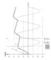
次に、図16と図17を用いて、対称インピーダンス制御の応答と非対称インピーダンス制御の応答を比較する。 Next, the response of the symmetric impedance control and the response of the asymmetric impedance control will be compared using FIG. 16 and FIG.
まず、図16には正弦波外力Fに対する対称インピーダンス制御の応答(Ys、Yh)を示す。図16のグラフでは、運動方程式の係数パラメーター(仮想質量、仮想粘性、仮想剛性)の設定を同図に示すPR1とした時の外力Fに対する応答をYsとし、係数パラメーターの設定をPR2とした時の応答をYhとして表す。なお、図16及び図17では、縦軸を任意目盛、横軸を時間(秒)とし、駆動周期をマニピュレーターの電流制御ループの周期と同じ125マイクロ秒(8kサンプル/秒)とし、外力を1秒周期の正弦波であるとする。 First, FIG. 16 shows the response (Y s , Y h ) of the symmetrical impedance control with respect to the sinusoidal external force F. In the graph of FIG. 16, the coefficient parameters of the equation of motion (virtual mass, virtual viscous, virtual stiffness) a response to the external force F when the setting of the PR1 shown in FIG. And Y s, and a set of coefficients parameters and PR2 the response when expressed as Y h. 16 and 17, the vertical axis is an arbitrary scale, the horizontal axis is time (seconds), the driving cycle is 125 microseconds (8 ksamples / second), which is the same as the cycle of the current control loop of the manipulator, and the external force is 1 Suppose that it is a sine wave with a period of seconds.
図16のPR1とPR2では、仮想質量mと仮想粘性μは同じであるが、仮想剛性kについてはPR2がPR1の2倍大きい。そのため、ロボットは、PR1設定時にはいわゆる軟らかいバネのような応答をし、PR2設定時にはPR1設定時の2倍硬いバネのような応答をする。なお、粘性項、質量項があるため、PR1又はPR2設定時の応答の位相は、外力の位相とずれる。 In PR1 and PR2 in FIG. 16, the virtual mass m and the virtual viscosity μ are the same, but with respect to the virtual stiffness k, PR2 is twice as large as PR1. Therefore, the robot responds like a so-called soft spring when setting PR1, and responds like a spring that is twice as hard as setting PR1 when setting PR2. Since there are a viscosity term and a mass term, the phase of response when setting PR1 or PR2 is shifted from the phase of external force.
図16を見てわかる通り、振幅や周期が違うものの、応答Ys及び応答Yhは、どちらも外力Fの方向(符号)に対して対称な正弦波となる。 As can be seen from FIG. 16, the response Y s and the response Y h are both sine waves symmetric with respect to the direction (sign) of the external force F, although the amplitude and period are different.
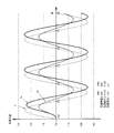
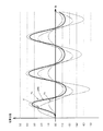
次に、正弦波外力Fに対する非対称インピーダンス制御の応答Ynを図17に示す。同図に示すYnは、外力の方向に応じて運動方程式の係数パラメーターを切り替える非対称インピーダンス制御の応答(変位、補正値)である。 Next, FIG. 17 shows the response Y n of the asymmetric impedance control to the sinusoidal external force F. Y n shown in the figure, the response of the asymmetric impedance control for switching the coefficient parameters of the equation of motion in response to the external force direction (displacement, correction value) is.
係数パラメーターとしては、同図に示すPR3とPR4を用いる。外力の方向が左方向(第2の方向)である場合に設定する係数パラメーターをPR3とし、外力の方向が右方向(第1の方向)である場合に設定する係数パラメーターをPR4とする。図17のPR3とPR4は、仮想質量mは同じであるが、仮想粘性μについてはPR4の方がPR3の32倍大きく、仮想剛性kについてはPR4の方がPR3の4倍大きい。そのため、ロボットは、PR3設定時にはPR4設定時と比べて軟らかいバネのような応答をし、PR4設定時にはPR3設定時と比べて硬いバネのような応答をする。 As coefficient parameters, PR3 and PR4 shown in the figure are used. The coefficient parameter set when the direction of the external force is the left direction (second direction) is PR3, and the coefficient parameter set when the direction of the external force is the right direction (first direction) is PR4. Although PR3 and PR4 in FIG. 17 have the same virtual mass m, PR4 is 32 times larger than PR3 for virtual viscosity μ, and PR4 is 4 times larger than PR3 for virtual stiffness k. Therefore, the robot responds like a soft spring when setting PR3 compared to when setting PR4, and responds like a hard spring when setting PR4 compared to when setting PR3.
例えば、図17のグラフではT1の時点で外力が正(左方向)から負(右方向)になるため、PR4の係数パラメーターが設定される。そのため、応答Ynが負の方向へ移動しにくくなり、外力の変化に対する変位の変化量が小さくなる。一方、例えばT2の時点で外力が負(右方向)から正(左方向)になるため、PR3の係数パラメーターが設定される。そのため、応答Ynが正の方向へ移動しやすくなり、外力の変化に対する変位の変化量が大きくなる。 For example, in the graph of FIG. 17, since the external force changes from positive (left direction) to negative (right direction) at time T1, the coefficient parameter of PR4 is set. Therefore, it becomes difficult to move in response Y n in the negative direction, the amount of change in displacement with respect to the change of the external force is reduced. On the other hand, for example, since the external force changes from negative (right direction) to positive (left direction) at time T2, the coefficient parameter of PR3 is set. Therefore, it becomes easy to move in response Y n is the positive direction, the amount of change in displacement with respect to the change of the external force becomes large.
図17のようなインピーダンス制御を行えば、外力の方向に対して変位の変化量が非対称となるインピーダンス制御を行うことができる。このように、図16に示す応答Ys及びYhと図17の応答Ynの曲線を比べれば、対称インピーダンス制御の応答と非対称インピーダンス制御の応答の違いが分かる。 If impedance control as shown in FIG. 17 is performed, impedance control in which the amount of change in displacement is asymmetric with respect to the direction of external force can be performed. Thus, compared to curve a response Y n response Y s and Y h and 17 shown in FIG. 16, the differences in the response of the response and the asymmetric impedance control symmetric impedance control can be seen.
以上の本実施形態のロボット制御装置では、力覚センサー10から取得される検出センサー値に基づいて、ロボット100の目標軌道の補正値を出力する力制御部20と、目標軌道に対して補正値に基づく補正処理を行って目標値を求め、求めた目標値を出力する目標値出力部60と、目標値に基づいて、ロボット100のフィードバック制御を行うロボット制御部80と、を含む。そして、力制御部20は、検出センサー値により表される外力の方向が第1の方向である場合には、第1の力制御を行い、外力の方向が第1の方向と反対方向である第2の方向である場合には、第1の力制御とは異なる第2の力制御を行う。
In the robot control device of the present embodiment described above, the
まず、力制御は、力覚センサー10から取得される検出センサー値に基づいて、ロボット100の目標軌道の補正値を求め、求めた補正値を出力する。
First, in the force control, the correction value of the target trajectory of the
ここで、検出センサー値(センサー情報)とは、力覚センサー10からの出力値そのものであってもよいし、当該出力値に対して入力補正部30による補正処理が施されたものであってもよい。また、帯域制限部25(図12に記載)による帯域制限処理が施されたものであってもよい。さらに、これらと数学的に等価な情報であってもよい。
Here, the detection sensor value (sensor information) may be an output value from the
また、補正値とは、力制御部20により求められ、目標値出力部60により目標軌道を補正するために用いられる値のことである。例えば、補正値は、図7(D)のグラフに表される変位のことである。図7(D)のグラフ等に表された変位は、外力に対するインピーダンス制御の応答(出力)であり、実際にロボット100のマニピュレーター等が動いた距離等を表す値ではない。そのため、実際にロボット100のマニピュレーター等が動いた時の変位と区別するために、この変位のことを仮想変位(仮想的な変位)とも呼ぶ。なお、変換処理前の補正値は、中間値、中間補正値とも言い換えることができる。
The correction value is a value obtained by the
そして、目標値出力部は、目標軌道に対して補正値に基づく補正処理を行って目標値を求める。 Then, the target value output unit obtains the target value by performing correction processing based on the correction value with respect to the target trajectory.
ここで、目標値とは、ロボット100のフィードバック制御における目標値のことであり、ロボット制御部80における制御はこの目標値に基づいて行われる。目標値は目標軌道に対して補正値による補正処理を行うことで取得できる。
Here, the target value is a target value in the feedback control of the
また、目標軌道とは、狭義にはロボット100のエンドエフェクター部(エンドポイント)の空間的な目標位置の変化を表すものであってもよい。1つの目標位置は、例えば3次元空間座標xyz(姿勢も考慮すれば各軸周りの回転角uvwを追加してもよい)で表されることになり、目標軌道とは当該目標位置の集合となる。ただし、目標軌道はこれに限定されるものではなく、ロボット100の目標関節角の集合であってもよい。関節を持つロボット100では、各関節の角度を決定すると、フォワードキネマティクス処理によりエンドエフェクター部の位置は一意に決定される。つまり、N関節ロボットではN個の関節角(θ1〜θN)により1つの目標位置を表現できることになるから、当該N個の関節角の組を1つの目標関節角とすれば、目標軌道とは目標関節角の集合と考えることができる。よって、力制御部20から出力される補正値も、位置に関する値であってもよいし、関節角に関する値であってもよい。
Further, the target trajectory may represent a change in the spatial target position of the end effector section (end point) of the
具体例を図22(A)、図22(B)に示す。後述するように力制御における常微分方程式として、上式(1)の運動方程式を用いるのであれば、当該運動方程式の解は位置に関する値となる。よって、目標軌道が目標位置である場合には、解をそのまま補正値とすればよく、システム構成例は図22(A)のようになる。なお、目標値は位置に関する値でも関節角に関する値でもよいが、一般的にはロボット100のフィードバック制御は関節角を用いることが想定される。
Specific examples are shown in FIGS. 22A and 22B. As will be described later, if the equation of motion of the above equation (1) is used as an ordinary differential equation in force control, the solution of the equation of motion is a value related to the position. Therefore, when the target trajectory is the target position, the solution may be used as a correction value as it is, and a system configuration example is as shown in FIG. Note that the target value may be a value related to a position or a value related to a joint angle, but it is generally assumed that the feedback control of the
それに対して、目標値出力部60のインバースキネマティクス処理部64とは別に、力制御部20がインバースキネマティクス処理部23を含む図22(B)のようなケースも考えられる。例えば、目標値出力部60での目標軌道生成処理と、力制御部20での補正値出力処理とで、処理のタイミングや処理レートが異なる場合等である。その場合には、目標軌道は目標関節角であり、力制御部20では運動方程式の解に対して変換処理(例えばインバースキネマティクス処理)を行って補正値とすることになる。
On the other hand, a case as shown in FIG. 22B in which the
また、力制御における常微分方程式とは、力制御において解を求める必要がある常微分方程式のことである。狭義には線形常微分方程式であってもよい。さらに狭義には、ロボットにあたかも所望の特性(質量・粘性・弾性等)を持つようにふるまわせるために解を求める必要がある常微分方程式のことであり、式(1)に示したような運動方程式であってもよい。 In addition, the ordinary differential equation in force control is an ordinary differential equation that requires a solution in force control. In the narrow sense, it may be a linear ordinary differential equation. In a more narrow sense, it is an ordinary differential equation that requires a solution to behave as if the robot had the desired characteristics (mass, viscosity, elasticity, etc.), as shown in equation (1) It may be an equation of motion.
そして、力制御部20は、検出センサー値により表される外力の方向が第1の方向である場合には、第1の力制御を行い、外力の方向が第1の方向と反対方向である第2の方向である場合には、第1の力制御と異なる第2の力制御を行う。なお、第1の力制御と第2の力制御の詳細については、後述する。
Then, when the direction of the external force represented by the detection sensor value is the first direction, the
これにより、外力の方向に対して変位の変化量が非対称となるインピーダンス制御を行うことが可能となる。このことは、ロボットの実用上非常に有効であり、より作業適応度の高い力制御を実現することができる。 This makes it possible to perform impedance control in which the amount of change in displacement is asymmetric with respect to the direction of the external force. This is very effective in practical use of the robot, and can realize force control with higher work adaptability.
また、力制御部20は、外力の方向が第1の方向である場合には、外力に対する変位変化量が第1の変位変化量となる力制御を、第1の力制御として行い、外力の方向が第2の方向である場合には、外力に対する変位変化量が第1の変位変化量とは異なる第2の変位変化量となる力制御を、第2の力制御として行ってもよい。
Further, when the direction of the external force is the first direction, the
ここで、変位変化量とは、外力に対する変位の変化量のことをいう。例えば、図7(D)のグラフにおいては、変位変化量は変位を表す直線の傾きのことをいう。言い換えれば、ロボットのマニピュレーターに一定方向から力を加え、それを徐々に変化させてマニピュレーターの瞬間的な変位を測定し、図7(A)〜図7(D)のようにグラフ化した時、ある大きさの外力に対するグラフの傾きが変位変化量となる。 Here, the displacement change amount means a change amount of displacement with respect to an external force. For example, in the graph of FIG. 7D, the displacement change amount refers to the slope of a straight line representing the displacement. In other words, when a force is applied to the manipulator of the robot from a certain direction, the momentary displacement of the manipulator is measured by gradually changing the force, and the graph is plotted as shown in FIGS. 7 (A) to 7 (D). The gradient of the graph with respect to an external force of a certain magnitude is the displacement change amount.
そのため、このような変位変化量を確認するためには、例えば、互いに大きさの異なる第1の外力、第2の外力、第3の外力をロボットのマニピュレーターに与え、第1の外力を与えた時のマニピュレーターの変位と第2の外力を与えた時の変位、第3の外力を与えた時の変位をそれぞれ求める。そして、第1の外力を与えた時のマニピュレーターの変位と第2の外力を与えた時の変位との差や、第2の外力を与えた時の変位と第3の外力を与えた時の変位との差を、変位変化量として確認できる。なお、第1の外力と第2の外力(第2の外力と第3の外力)の差を微小にすれば、グラフの傾きと同様の値を求めることができる。すなわち、変位変化量は、第1の外力を加えた時の変位と、第1の外力と異なる第2の外力を加えた時の変位との差ということもできる。そしてこの時、第1の外力と第2の外力との差が微小であっても良い。ここで、微小とは0に限りなく近いことをいう。 Therefore, in order to confirm such a displacement change amount, for example, the first external force, the second external force, and the third external force having different sizes are applied to the manipulator of the robot, and the first external force is applied. The displacement of the manipulator at the time, the displacement when the second external force is applied, and the displacement when the third external force is applied are obtained. Then, the difference between the displacement of the manipulator when the first external force is applied and the displacement when the second external force is applied, and the displacement when the second external force is applied and the third external force are applied. The difference from the displacement can be confirmed as the displacement change amount. If the difference between the first external force and the second external force (second external force and third external force) is made small, a value similar to the slope of the graph can be obtained. That is, the displacement change amount can also be referred to as a difference between the displacement when the first external force is applied and the displacement when the second external force different from the first external force is applied. At this time, the difference between the first external force and the second external force may be minute. Here, minute means that it is close to zero.
また、上記のように変位変化量を確認した際に、外力に比例して変位が大きくなるようであれば、変位と外力とに図7(A)のような関係が成り立っていることが分かり、外力を大きくしているにも関わらず変位が大きくならないようであれば、変位と外力とに図7(B)のような関係が成り立っていることが分かる。 Further, when the displacement change amount is confirmed as described above, if the displacement increases in proportion to the external force, it is understood that the relationship between the displacement and the external force is as shown in FIG. If the displacement does not increase even though the external force is increased, it can be seen that the relationship shown in FIG. 7B is established between the displacement and the external force.
このように第1の変位変化量と第2の変位変化量とが異なる力制御を行うことにより、非対称インピーダンス制御を実現することができる。例えば第1の方向への外力を検出した場合には、変位変化量が大きくなるような力制御を行い、第2の方向への外力を検出した場合には、変位変化量が小さくなるような力制御を行うこと等が可能になる。すなわち、図7(D)のグラフのような力制御が可能になる。 Thus, by performing force control in which the first displacement change amount and the second displacement change amount are different, asymmetric impedance control can be realized. For example, when an external force in the first direction is detected, force control is performed so that the displacement change amount becomes large. When an external force in the second direction is detected, the displacement change amount becomes small. It is possible to perform force control. That is, force control as shown in the graph of FIG.
また、力制御部20は、外力の方向が第1の方向である場合には、前記第1の変位変化量に対応する第1の補正値を出力する第1の力制御を行い、外力の方向が第2の方向である場合には、前記第2の変位変化量に対応する第2の補正値を出力する第2の力制御を行ってもよい。
In addition, when the direction of the external force is the first direction, the
すなわち、上述した第1の力制御とは、第1の補正値を出力する力制御のことでもあり、上述した第2の力制御とは、第2の補正値を出力する力制御のことでもある。 That is, the above-described first force control is also force control that outputs the first correction value, and the above-described second force control is also force control that outputs the second correction value. is there.
これにより、外力の方向に応じて異なる補正値を出力すること等が可能になる。 This makes it possible to output different correction values depending on the direction of the external force.
また、力制御部20は、検出センサー値により表される外力の方向を判定する外力方向判定部27を含んでもよい。
The
これにより、外力の方向を判定すること等が可能になる。 This makes it possible to determine the direction of the external force.
また、力制御部20は、力制御における制御パラメーターセットを複数記憶する制御パラメーター記憶部24と、制御パラメーター記憶部24に記憶された制御パラメーターセットの中から、使用する制御パラメーターセットの選択処理を行う制御パラメーター選択部26と、を有してもよい。そして、力制御部20は、検出センサー値により表される外力の方向が第1の方向である場合には、第1の制御パラメーターセットを選択する選択処理を行い、外力の方向が第2の方向である場合には、第2の制御パラメーターセットを選択する選択処理を行い、選択した制御パラメーターセットを用いて、力制御における常微分方程式の解を補正値として求め、補正値を出力してもよい。
In addition, the
ここで、制御パラメーターセットとは、力制御における常微分方程式の各項の係数パラメーターのセットであってもよいし、デジタルフィルターのパラメーターセットであってもよい。 Here, the control parameter set may be a set of coefficient parameters for each term of the ordinary differential equation in force control, or may be a parameter set of a digital filter.
また、常微分方程式の各項の係数パラメーターとは、常微分方程式における定数項、1階微分項の係数、2階微分項の係数、・・・n階微分項の係数を指すものとする。上述した式(1)の例であれば、m、μ、kが係数パラメーターとなる。 In addition, the coefficient parameter of each term of the ordinary differential equation refers to a constant term, a coefficient of the first derivative term, a coefficient of the second derivative term,..., A coefficient of the nth derivative term in the ordinary differential equation. In the case of the above-described equation (1), m, μ, and k are coefficient parameters.
一方、デジタルフィルターのパラメーターとは、式(4)における各項の係数を指す。具体的には、C0、C1、C2のことである。なお、第1のパラメーターセットと第2のパラメーターセットは、いずれかのパラメーターが異なっているものとする。 On the other hand, the parameter of the digital filter refers to the coefficient of each term in Equation (4). Specifically, it is C 0 , C 1 , C 2 . Note that any one of the first parameter set and the second parameter set is different.
なお、本実施形態では、外力の方向に基づいて、インピーダンス制御に用いる制御パラメーターセットの選択処理を行っているが、外力の方向ではなく仮想変位に基づいて、選択処理を行っても良い。 In this embodiment, the selection process of the control parameter set used for impedance control is performed based on the direction of the external force. However, the selection process may be performed based on the virtual displacement instead of the direction of the external force.
これにより、インピーダンス制御に用いる制御パラメーターセットを切り替えることで、非線形インピーダンス制御を実現すること等が可能となる。 Thus, it is possible to realize nonlinear impedance control by switching the control parameter set used for impedance control.
また、力制御部20は、検出センサー値により表される外力の方向が第2の方向である場合には、第1の力制御を行って求めた第1の補正値と、第2の力制御を行って求めた第2の補正値とに対して重み付け処理を行って、第3の補正値を求め、求めた第3の補正値を出力してもよい。
Further, when the direction of the external force represented by the detection sensor value is the second direction, the
例えば、力制御部20は、重み付け処理後の第1の補正値と第2の補正値との和を第3の補正値として求めてもよい。
For example, the
具体例として、2つのインピーダンス処理出力の重み付け加算の例を図18に示す。これは図16と同じ2組の制御パラメーター(PR1とPR2)を用いた場合であるが、本例では、パラメーターを切り替えるのではなく、2組のインピーダンス処理を並列動作させ、その出力を重み付け加算している。 As a specific example, an example of weighted addition of two impedance processing outputs is shown in FIG. This is the case where the same two sets of control parameters (PR1 and PR2) as in FIG. 16 are used. In this example, instead of switching the parameters, the two sets of impedance processing are operated in parallel and the outputs are weighted and added. doing.
図18においては、外力がF、外力Fに対して、図16に示す運動方程式の係数パラメーターセットPR1を用いてインピーダンス制御を行った時の応答がYs、係数パラメーターセットPR2を用いてインピーダンス制御を行った時の応答がYh、応答YsとYhとの重み付け加算値がCPRとなる。なお、本例では、外力の方向に関わらず、常に重み付け和(CPR)を求めている。 In FIG. 18, the response when the impedance control is performed using the coefficient parameter set PR1 of the equation of motion shown in FIG. 16 for the external force F and the external force F is Y s , and the impedance control is performed using the coefficient parameter set PR2. the response when done by Y h, the weighted sum of the responses Y s and Y h is CPR. In this example, the weighted sum (CPR) is always obtained regardless of the direction of the external force.
また、重みWは式(5)のようになり、重み付け加算値(出力値、補正値)Outputは式(6)のようになる。本実施形態では、このようにして求めた重み付け加算値を補正値として求めても良い。 Also, the weight W is as shown in equation (5), and the weighted addition value (output value, correction value) Output is as shown in equation (6). In the present embodiment, the weighted addition value obtained in this way may be obtained as a correction value.
![]()
![]()
![]()
![]()
なお、重み付け関数は、正負両方向に飽和特性を持ち、単調増加関数であれば他の関数でも良いが、ここではtanhあるいはシグモイド関数(実質的にはtanhと同一のもの)を用いる。シグモイド関数は2値の系の最大エントロピー状態を与える関数であり、さまざまな場面で現れる。ただし、ここで最大エントロピーに特別の意味があるわけではない。 Note that the weighting function has saturation characteristics in both positive and negative directions and may be another function as long as it is a monotonously increasing function. Here, a tanh or sigmoid function (substantially the same as tanh) is used. The sigmoid function is a function that gives the maximum entropy state of a binary system and appears in various situations. However, the maximum entropy does not have any special meaning here.
これにより、制御パラメーターの切り替えではなく、複数のデジタルフィルターのパラメーターを用いて、デジタルフィルター処理を行った時の出力値を求め、各出力値の重み付け加算を行うことにより補正値を求めて、非対称インピーダンス制御を実現すること等が可能になる。 As a result, instead of switching control parameters, using multiple digital filter parameters, the output value when digital filter processing is performed is obtained, and the correction value is obtained by weighted addition of each output value. Impedance control can be realized.
また、力制御部20は、力制御における常微分方程式の解を補正値として求めるデジタルフィルター部22を有してもよい。
Further, the
これにより、常微分方程式の解を求めるという力制御において必要な処理を、デジタルフィルターを用いて行うことが可能になるため、Newton法、Runge−Kutta法等の手法を用いる場合に比べて、ハードウェアー化が容易である。そして、デジタルフィルター処理に用いるデジタルフィルターを切り替える(例えばフィルター係数を切り替える)ことで、簡単に応答特性を切り替えることも可能となる。 This makes it possible to use a digital filter to perform a process necessary for force control to obtain a solution of an ordinary differential equation, and therefore, compared with a case where a method such as a Newton method or a Runge-Kutta method is used. Easy to wear. The response characteristics can be easily switched by switching the digital filter used for the digital filter processing (for example, switching the filter coefficient).
また、力制御部20は、補正値を求めるデジタルフィルター部22の動作の安定度を判定し、デジタルフィルター部22の動作が安定であると判定された場合に、力制御における常微分方程式の解を補正値として求めてもよい。
Further, the
これにより、デジタルフィルターの安定性を判定すること等が可能になる。力制御における常微分方程式の係数パラメーターは、設定次第では現実にはあり得ない系(例えば発振するロボット等)を作ってしまうことがある。そのため、常微分方程式の安定性を判定する必要があるが、デジタルフィルターを用いれば、その判定が容易となる。 This makes it possible to determine the stability of the digital filter. Depending on the setting, the coefficient parameter of the ordinary differential equation in force control may create a system (for example, an oscillating robot) that is impossible in reality. Therefore, it is necessary to determine the stability of the ordinary differential equation. However, if a digital filter is used, the determination becomes easy.
また、常微分方程式は、仮想質量項、仮想粘性項及び仮想弾性項を係数パラメーターとする運動方程式であってもよい。 The ordinary differential equation may be an equation of motion having a virtual mass term, a virtual viscosity term, and a virtual elasticity term as coefficient parameters.
これにより、運動方程式の解を求めること等が可能になる。よって、ロボット100に対して、あたかも仮想質量項に対応する質量、仮想粘性項に対応する粘性、仮想弾性項に対応する弾性を持つかのようにふるまわせることが可能になる。
Thereby, it is possible to obtain a solution of the equation of motion. Therefore, the
また、以上の本実施形態は、上述してきたロボット制御装置(力制御部20、目標値出力部60、ロボット制御部80を含む)と、目標値出力部60から取得される目標値に基づいて、各部を動作させるロボット100を含むロボットシステムに関係する。
Further, the present embodiment described above is based on the above-described robot control device (including the
これにより、ロボット制御装置にとどまらず、本実施形態の処理を実行するロボットシステムを実現すること等が可能になる。 As a result, it is possible to realize a robot system that executes the processing of this embodiment as well as the robot control device.
なお、上記ではデジタルフィルターを用いて力制御を行う場合について述べたが、デジタルフィルターを他の構成要素により代替することも可能である。デジタルフィルターを他の構成要素により代替した場合も、本発明の範囲に含まれるものとする。 In the above description, the case where force control is performed using a digital filter has been described. However, the digital filter may be replaced by other components. The case where the digital filter is replaced by another component is also included in the scope of the present invention.
3.第2の実施形態
第2の実施形態では、所定の制御パラメーター変更指示があった場合等に、制御パラメーターを変更して、非対称インピーダンス制御を行う。
3. Second Embodiment In the second embodiment, when a predetermined control parameter change instruction is given, the control parameter is changed to perform asymmetric impedance control.
3.1 構成
図19に第2の実施形態に係るロボット制御装置の構成例を示す。
3.1 Configuration FIG. 19 shows a configuration example of a robot control apparatus according to the second embodiment.
ロボット制御装置の力制御部20は、インピーダンス処理部21と、第1の制御パラメーター記憶部24−1と、第2の制御パラメーター記憶部24−2と、閾値記憶部(基準外力方向記憶部)24−3と、制御パラメーター選択部26と、外力方向判定部(外力方向・外力値判定部)27と、状態設定部(リセット部)29と、を含む。なお、本実施形態の力制御部20は、図19の構成には限定されず、その一部の構成要素を省略したり、他の構成要素を追加したりするなどの種々の変形実施が可能である。
The
ここでは、力覚センサー10、入力補正部30、フォワードキネマティクス処理部40、目標値出力部60(軌道生成部62、インバースキネマティクス処理部64)、ロボット制御部80(モーター制御部82−1〜モーター制御部82−N)、インピーダンス処理部21、第1の制御パラメーター記憶部24−1、第2の制御パラメーター記憶部24−2等については図13と同様であるため説明は省略し、図13と異なる構成又は動作をする機能部についてのみ説明を行う。
Here, the
まず、閾値記憶部(基準外力方向記憶部)24−3は、制御パラメーターを変更するか否かの判定処理に用いる所定の閾値や後述する基準外力方向を記憶する。閾値記憶部(基準外力方向記憶部)24−3の機能は、RAM等のメモリーやHDD(ハードディスクドライブ)などにより実現できる。実際には第1の制御パラメーター記憶部24−1及び第2の制御パラメーター記憶部24−2と共通の単一のメモリー等により構成されていても良いし、それぞれ別の複数のメモリー等により構成されていても良い。 First, the threshold value storage unit (reference external force direction storage unit) 24-3 stores a predetermined threshold value used for determining whether to change the control parameter or a reference external force direction to be described later. The function of the threshold storage unit (reference external force direction storage unit) 24-3 can be realized by a memory such as a RAM or an HDD (hard disk drive). Actually, the first control parameter storage unit 24-1 and the second control parameter storage unit 24-2 may be configured by a single memory or the like, or may be configured by a plurality of different memories. May be.
次に、外力方向判定部(外力方向・外力値判定部)27は、外力の方向を判定する他にも、検出センサー値に基づいて、閾値記憶部24−3から取得される所定の閾値よりも外力値が大きいか否か等を判定しても良い。 Next, the external force direction determination unit (external force direction / external force value determination unit) 27 determines a direction of the external force and, based on the detection sensor value, based on a predetermined threshold acquired from the threshold storage unit 24-3. Alternatively, it may be determined whether or not the external force value is large.
さらに、制御パラメーター選択部26は、外力方向判定部(外力方向・外力値判定部)27から取得される外力の方向や外力と閾値との大小関係を表す情報に基づいて、使用する制御パラメーターを選択する。なお、外力方向判定部27ではなく、制御パラメーター選択部26が、所定の閾値よりも外力値が大きいか否か等を判定しても良い。
Further, the control
そして、状態設定部(リセット部)29は、制御パラメーター変更指令やリセット信号を取得した場合に、制御パラメーター選択部にその旨を通知する。 Then, when the state setting unit (reset unit) 29 acquires a control parameter change command or a reset signal, the state setting unit (reset unit) 29 notifies the control parameter selection unit to that effect.
なお、第2の実施形態においても、第1の実施形態と同様に図10に示すデジタルフィルターを利用することができる。 In the second embodiment, the digital filter shown in FIG. 10 can be used as in the first embodiment.
3.2 詳細な処理
次に図20のフローチャートを用いて、本実施形態における力制御部が行うデジタルフィルター処理の流れを説明する。
3.2 Detailed Processing Next, the flow of the digital filter processing performed by the force control unit in the present embodiment will be described using the flowchart of FIG.
ステップS301、S302までの流れは図14と同様である。なお、本実施形態の初期状態では、デジタルフィルターのパラメーターセットとして、第1のパラメーターセットPR1を用いる。 The flow up to steps S301 and S302 is the same as in FIG. In the initial state of the present embodiment, the first parameter set PR1 is used as the parameter set of the digital filter.
また、本実施形態では、外力値F(外力の方向と大きさ)に基づいて、使用するデジタルフィルターのパラメーターセットを変更する。その様子を、横軸を外力値Fとし、縦軸を制御パラメーターとするグラフを用いて図21に表す。 In the present embodiment, the parameter set of the digital filter to be used is changed based on the external force value F (direction and magnitude of the external force). This state is shown in FIG. 21 using a graph in which the horizontal axis is an external force value F and the vertical axis is a control parameter.
前述した通り、初期状態では第1のパラメーターセットPR1を選択しているため、図21に示されるように、外力値Fが第2の閾値Th2よりも大きいことが想定される。さらに、第2の閾値Th2以下であるならば、使用するデジタルフィルターのパラメーターセットを第2のパラメーターセットPR2に変更すべきである。 As described above, since the first parameter set PR1 is selected in the initial state, it is assumed that the external force value F is larger than the second threshold Th2, as shown in FIG. Furthermore, if it is less than or equal to the second threshold Th2, the parameter set of the digital filter to be used should be changed to the second parameter set PR2.
そのため、まず現在設定されている閾値が第2の閾値Th2であるか否かを判定する(S303)。 For this reason, it is first determined whether or not the currently set threshold is the second threshold Th2 (S303).
そして、現在設定されている閾値が第2の閾値Th2であると判定した場合には、外力値Fが第2の閾値以下か否かを判定する(S304)。 When it is determined that the currently set threshold is the second threshold Th2, it is determined whether or not the external force value F is equal to or less than the second threshold (S304).
外力値Fが第2の閾値Th2以下であると判定した場合には、デジタルフィルターのパラメーターセットを第2のパラメーターセットPR2に設定する(S305)。 If it is determined that the external force value F is equal to or less than the second threshold Th2, the digital filter parameter set is set to the second parameter set PR2 (S305).
ここで、第2のパラメーターセットを使用する状態(以下、第2の状態と呼ぶ)から第1のパラメーターセットを使用する状態(以下、第1の状態と呼ぶ)へ遷移するか否かを判定する際の比較処理においても、第2の閾値Th2を用いると、外力値Fが第2の閾値Th2付近の値である場合に、使用するデジタルフィルターのパラメーターセットが頻繁に変化してしまうことがある。使用するデジタルフィルターのパラメーターセットが変化すると、応答特性も変化するため、このような頻繁な変更は通常好ましくない。 Here, it is determined whether or not a transition is made from a state using the second parameter set (hereinafter referred to as the second state) to a state using the first parameter set (hereinafter referred to as the first state). Also in the comparison processing at this time, if the second threshold value Th2 is used, the parameter set of the digital filter to be used may frequently change when the external force value F is a value near the second threshold value Th2. is there. Such frequent changes are usually not preferred because the response characteristics change as the parameter set of the digital filter used changes.
そこで、デジタルフィルターのパラメーターセットの変更制御にヒステリシス特性を与えるため、ステップS305の後に、閾値を第1の閾値Th1に変更する(S306)。これにより、使用するデジタルフィルターのパラメーターセットの変更が頻繁に起こることを防ぐことができる。 Therefore, in order to give hysteresis characteristics to the change control of the parameter set of the digital filter, the threshold value is changed to the first threshold value Th1 after step S305 (S306). This can prevent frequent changes in the parameter set of the digital filter to be used.
一方で、ステップS304において外力値Fが第2の閾値よりも大きいと判定した場合には、使用するデジタルフィルターのパラメーターセットの変更処理は行わない。 On the other hand, if it is determined in step S304 that the external force value F is greater than the second threshold value, the parameter set change process for the digital filter to be used is not performed.
そして、ステップS306の処理後又はステップS304において外力値Fが第2の閾値よりも大きいと判定した場合に、ステップS310の処理を行い、Ynを求め(S310)、ステップS301に戻る。 Then, when an external force value F is determined to be greater than the second threshold value in the process or after step S304 in step S306, it performs processing step S310, the seek Y n (S310), the flow returns to step S301.
一方、第2の状態から第1の状態への遷移判定をする場合には、前述したように外力値Fと第1の閾値Th1を比較する。なお、第2の状態である場合には、外力値Fと比較する閾値として第1の閾値Th1が設定されているはずである(ステップS306参照)。 On the other hand, when determining the transition from the second state to the first state, the external force value F and the first threshold value Th1 are compared as described above. In the second state, the first threshold value Th1 should be set as a threshold value to be compared with the external force value F (see step S306).
そこで、ステップS303において、現在設定されている閾値が第2の閾値Th2ではないと判定した(すなわち、第1の閾値Th1が設定されていると判定した)場合には、外力値Fが第1の閾値Th1以上か否かを判定する(S307)。 Therefore, if it is determined in step S303 that the currently set threshold is not the second threshold Th2 (that is, it is determined that the first threshold Th1 is set), the external force value F is the first threshold value F1. It is determined whether or not the threshold Th1 is greater than or equal to (S307).
外力値Fが第1の閾値Th1以上であると判定した場合には、デジタルフィルターのパラメーターセットを第1のパラメーターセットPR1に設定する(S308)。そして、ステップS306と同様に、使用するデジタルフィルターのパラメーターセットの変更制御にヒステリシス特性を持たせるために、閾値を第2の閾値Th2に変更する(S309)。 If it is determined that the external force value F is greater than or equal to the first threshold Th1, the digital filter parameter set is set to the first parameter set PR1 (S308). Then, as in step S306, the threshold value is changed to the second threshold value Th2 in order to give hysteresis characteristics to the change control of the parameter set of the digital filter to be used (S309).
一方で、ステップS307において外力値Fが第1の閾値Th1よりも小さいと判定した場合には、使用するデジタルフィルターのパラメーターセットの変更処理は行わない。 On the other hand, if it is determined in step S307 that the external force value F is smaller than the first threshold value Th1, the parameter set change process for the digital filter to be used is not performed.
そして、ステップS309の処理後又はステップS307において外力値Fが第1の閾値Th1よりも小さいと判定した場合に、ステップS310の処理を行い、Ynを求め(S310)、ステップS301に戻る。以上が本実施形態のデジタルフィルター処理の流れである。 Then, when an external force value F is determined to be smaller than the first threshold Th1 in the process or after step S307 in step S309, the performs processing step S310, the seek Y n (S310), the flow returns to step S301. The above is the flow of the digital filter processing of this embodiment.
以上の本実施形態のロボット制御装置の力制御部20は、第1の制御パラメーターセットを用いて力制御を行っている時に、所定の制御パラメーター変更指示があったと判断された場合に、使用する制御パラメーターセットを第1の制御パラメーターセットから第2の制御パラメーターセットへと変更する変更処理を行ってもよい。
The
ここで、所定の制御パラメーター変更指示とは、前述したように外力値と所定の閾値との比較結果のことであってもよいし、状態設定部29から出力される制御パラメーターの変更命令のことであってもよい。
Here, the predetermined control parameter change instruction may be a comparison result between the external force value and the predetermined threshold as described above, or a control parameter change instruction output from the
例えば、所定の制御パラメーター変更指示が前者である場合には、外力値が所定の閾値よりも大きいという比較結果を制御パラメーター選択部26が取得した時に、使用する制御パラメーターセットの変更処理を行う。
For example, when the predetermined control parameter change instruction is the former, when the control
一方で、例えば、所定の制御パラメーター変更指示が後者である場合には、以下のような処理を行う。 On the other hand, for example, when the predetermined control parameter change instruction is the latter, the following processing is performed.
まず、本実施形態のロボット制御装置の力制御部20は、基本外力方向記憶部24−3を持つ。なお、基本外力方向記憶部24−3は閾値記憶部と同じメモリー等であってもよい。また、初期状態では、基本外力方向記憶部24−3に記憶された基本外力方向に対応する制御パラメーターセット(第1の制御パラメーター)が設定されているものとする。
First, the
そして、基本外力方向と異なる方向の外力が検出された時に、第1の制御パラメーターセットとは異なる第2の制御パラメーターセットを制御パラメーター選択部26が選択する。ただし、状態設定部29から制御パラメーターセットの変更命令が出力されるまでは、第1の制御パラメーターセットが設定されている状態を維持する。そして、状態設定部29から制御パラメーターセットの変更命令が出力された時に初めて、選択された制御パラメーターセットを設定する。また、状態設定部29が、初期状態への戻すことを指示するリセット信号を出力した場合には、制御パラメーター選択部26は、第1の制御パラメーターセットを設定し直す。
When an external force in a direction different from the basic external force direction is detected, the control
これにより、所定の制御パラメーター変更指示があった場合に、使用する制御パラメーターセットを変更すること等が可能になる。 This makes it possible to change the control parameter set to be used when a predetermined control parameter change instruction is issued.
また、力制御部20は、第2の制御パラメーターセットを用いて力制御を行っている場合には、第1の方向への外力の大きさが第1の閾値を超えたと判断した時に、使用する制御パラメーターセットを第1の制御パラメーターセットに変更する変更処理を行い、第1の制御パラメーターセットを用いて力制御を行っている場合には、第2の方向への外力の大きさが第2の閾値を超えたと判断した時に、使用する制御パラメーターセットを第2の制御パラメーターセットに変更する変更処理を行ってもよい。
Further, when the
ここで、第2の方向は、第1の方向と同一軸上での反対方向のことをいう。 Here, the second direction refers to the opposite direction on the same axis as the first direction.
また、ここでは外力の方向を区別し、外力の大きさを正の数、すなわち絶対値で表している。一方、上述した例では、図21に示すように、第1の方向への外力の大きさと第1の閾値とを正の数で表し、第2の方向への外力の大きさと第2の閾値とを負の数で表している。しかし、これらは表現上での差異であるため、本質的には同一のものである。 Here, the direction of the external force is distinguished, and the magnitude of the external force is represented by a positive number, that is, an absolute value. On the other hand, in the above-described example, as shown in FIG. 21, the magnitude of the external force in the first direction and the first threshold value are represented by positive numbers, and the magnitude of the external force in the second direction and the second threshold value. And are expressed as negative numbers. However, since these are differences in expression, they are essentially the same.
これにより、上述したように、制御パラメーターセットの変更制御にヒステリシス特性を与えることができ、使用する制御パラメーターセットの変更が頻繁に起こることを回避すること等が可能になる。 Thereby, as described above, it is possible to give a hysteresis characteristic to the control parameter set change control, and to avoid frequent changes in the control parameter set to be used.
また、力覚センサーに第1の外力が加えられた場合のロボットの変位の大きさと、力覚センサーに第1の外力と同じ大きさであって反対の方向の力である第2の外力が加えられた場合のロボットの変位の大きさとが異なる力制御を行ってもよい。 Further, the magnitude of the displacement of the robot when the first external force is applied to the force sensor and the second external force that is the same magnitude as the first external force and that is in the opposite direction are applied to the force sensor. Force control different from the magnitude of the displacement of the robot when added may be performed.
以上のように本実施形態について詳細に説明したが、本発明の新規事項および効果から実体的に逸脱しない多くの変形が可能であることは当業者には容易に理解できるであろう。従って、このような変形例はすべて本発明の範囲に含まれるものとする。例えば、明細書又は図面において、少なくとも一度、より広義または同義な異なる用語と共に記載された用語は、明細書又は図面のいかなる箇所においても、その異なる用語に置き換えることができる。また、ロボット制御装置及びロボットシステムの構成、動作も本実施形態で説明したものに限定されず、種々の変形実施が可能である。 Although the present embodiment has been described in detail as described above, it will be easily understood by those skilled in the art that many modifications can be made without departing from the novel matters and effects of the present invention. Accordingly, all such modifications are intended to be included in the scope of the present invention. For example, a term described at least once together with a different term having a broader meaning or the same meaning in the specification or the drawings can be replaced with the different term in any part of the specification or the drawings. The configurations and operations of the robot control device and the robot system are not limited to those described in the present embodiment, and various modifications can be made.
10 力覚センサー、20 力制御部、21 インピーダンス処理部、
22 デジタルフィルター部、23 インバースキネマティクス処理部、
24−1 第1の制御パラメーター記憶部、
24−2 第2の制御パラメーター記憶部、
24−3 閾値記憶部(基準外力方向記憶部)、
25 帯域制限部、26 制御パラメーター選択部、27 外力方向判定部、
29 状態設定部、30 入力補正部、40 フォワードキネマティクス処理部、
60 目標値出力部、62 軌道生成部、64 インバースキネマティクス処理部、
80 ロボット制御部、82−1〜82−N 駆動制御部(モーター制御部)、
100 ロボット、102−1〜102−N 駆動部(モーター)、
221 デジタルフィルター演算部、222 デジタルフィルター係数出力部、
223 デジタルフィルター安定度判定部、224 デジタルフィルター係数記憶部、
225 デジタルフィルター係数変換部、300 制御装置、
310 ロボット(本体)、320 アーム、330 ハンド、
510 力覚センサー、532 姿勢補正部、534 ハンド・ツール自重補正部、
536 運動方程式処理部、540 フォワードキネマティクス処理部、
562 軌道生成部、564 インバースキネマティクス処理部
10 force sensor, 20 force control unit, 21 impedance processing unit,
22 digital filter section, 23 inverse kinematics processing section,
24-1 First control parameter storage unit,
24-2 Second control parameter storage unit,
24-3 threshold storage unit (reference external force direction storage unit),
25 Band limiting unit, 26 Control parameter selection unit, 27 External force direction determination unit,
29 status setting unit, 30 input correction unit, 40 forward kinematics processing unit,
60 target value output unit, 62 trajectory generation unit, 64 inverse kinematics processing unit,
80 robot controller, 82-1 to 82-N drive controller (motor controller),
100 robot, 102-1 to 102-N drive unit (motor),
221 digital filter operation unit, 222 digital filter coefficient output unit,
223 digital filter stability determination unit, 224 digital filter coefficient storage unit,
225 digital filter coefficient conversion unit, 300 controller,
310 robot (main body), 320 arm, 330 hand,
510 force sensor, 532 posture correction unit, 534 hand / tool self-weight correction unit,
536 motion equation processing unit, 540 forward kinematics processing unit,
562 Trajectory generator, 564 Inverse kinematics processor
Claims (17)
前記力制御部は、
前記外力の方向が前記第1の方向である場合には、外力に対する変位変化量が第1の変位変化量となるように前記第1の力制御を行い、
前記外力の方向が前記第2の方向である場合には、外力に対する前記変位変化量が前記第1の変化量とは異なる第2の変位変化量となるように前記第2の力制御を行うことを特徴とするロボット制御装置。 In claim 1,
The force control unit
When the direction of the external force is the first direction, the first force control is performed so that the displacement change amount with respect to the external force becomes the first displacement change amount,
When the direction of the external force is the second direction, the second force control is performed so that the displacement change amount with respect to the external force becomes a second displacement change amount different from the first change amount. A robot controller characterized by that.
前記力制御部は、
前記第1の変位変化量に対応する第1の補正値を出力する前記第1の力制御を行い、
前記第2の変位変化量に対応する第2の補正値を出力する前記第2の力制御を行うことを特徴するロボット制御装置。 In claim 2,
The force control unit
Performing the first force control to output a first correction value corresponding to the first displacement change amount;
A robot control apparatus that performs the second force control to output a second correction value corresponding to the second displacement change amount.
前記力制御部は、
前記検出値に基づき前記外力の方向を判定する外力方向判定部を含むことを特徴とするロボット制御装置。 In any one of Claims 1 thru | or 3,
The force control unit
A robot control apparatus comprising: an external force direction determination unit that determines a direction of the external force based on the detection value.
前記力制御部は、
力制御における前記制御パラメーターセットを複数記憶する制御パラメーター記憶部と、
前記制御パラメーター記憶部に記憶された前記制御パラメーターセットの中から、使用する前記制御パラメーターセットの選択処理を行う制御パラメーター選択部と、
を有し、
前記力制御部は、
前記外力の方向が前記第1の方向である場合には、前記第1の制御パラメーターセットを選択する前記選択処理を行い、
前記外力の方向が前記第2の方向である場合には、前記第2の制御パラメーターセットを選択する前記選択処理を行い、
選択した前記制御パラメーターセットを用いて、力制御におけるインピーダンス制御を行って補正値を求め、前記補正値を出力することを特徴とするロボット制御装置。 In any one of Claims 1 thru | or 4,
The force control unit
A control parameter memory unit for storing a plurality of said control parameters set in the force control,
A control parameter selection unit that performs a selection process of the control parameter set to be used from among the control parameter sets stored in the control parameter storage unit;
Have
The force control unit
If the direction of the external force is the first direction, it performs the selection processing of selecting the first set of control parameters,
If the direction of the external force is the second direction, it performs the selection processing of selecting the second set of control parameters,
Using the selected control parameter set, impedance control in force control is performed to obtain a correction value, and the robot control apparatus outputs the correction value.
前記力制御部は、
前記第1の制御パラメーターセットを用いて力制御を行っている時に、所定の制御パラメーター変更指示があったと判断した場合、使用する前記制御パラメーターセットを前記第1の制御パラメーターセットから前記第2の制御パラメーターセットへと変更する変更処理を行うことを特徴するロボット制御装置。 In claim 5,
The force control unit
When it is determined that a predetermined control parameter change instruction has been issued while performing force control using the first control parameter set, the control parameter set to be used is changed from the first control parameter set to the second control parameter set. A robot controller characterized by performing a change process for changing to a control parameter set.
前記力制御部は、
前記第2の制御パラメーターセットを用いて力制御を行っている時に前記第1の方向への外力の大きさが第1の閾値を超えたと判断した場合、使用する前記制御パラメーターセットを前記第1の制御パラメーターセットに変更する変更処理を行い、
前記第1の制御パラメーターセットを用いて力制御を行っている時に前記第2の方向への外力の大きさが第2の閾値を超えたと判断した場合、使用する前記制御パラメーターセットを前記第2の制御パラメーターセットに変更する前記変更処理を行うことを特徴とするロボット制御装置。 In any one of claims 1 to 6,
The force control unit
When it is determined that the magnitude of the external force in the first direction exceeds the first threshold when force control is performed using the second control parameter set, the control parameter set to be used is set to the first control parameter set. It performs a change process of changing to a set of control parameters,
When it is determined that the magnitude of the external force in the second direction has exceeded the second threshold when force control is performed using the first control parameter set, the control parameter set to be used is set to the second control parameter set. A robot control apparatus that performs the change processing to change to a control parameter set of
前記力制御部は、
前記検出値により表される外力の方向が前記第2の方向である場合には、前記第1の力制御を行って求めた第1の補正値と、前記第2の力制御を行って求めた第2の補正値とに対して重み付け処理を行って、第3の補正値を求め、求めた前記第3の補正値を出力することを特徴とするロボット制御装置。 In any one of Claims 1 thru | or 7,
The force control unit
When the direction of the external force represented by the detected value is the second direction, the first correction value obtained by performing the first force control and the second force control are obtained. A robot control apparatus that performs a weighting process on the second correction value to obtain a third correction value and outputs the obtained third correction value.
前記力制御部は、
力制御におけるインピーダンス制御を行って補正値を求めるデジタルフィルター部を有することを特徴するロボット制御装置。 In any one of Claims 1 thru | or 8.
The force control unit
Robot controller for wherein a digital filter unit for obtaining a correction value by performing the impedance control in the force control.
前記力制御部は、
前記補正値を求める前記デジタルフィルター部の動作の安定度を判定し、
前記デジタルフィルター部の前記動作が安定であると判定された場合に、力制御における前記インピーダンス制御を行って、前記補正値を求めることを特徴するロボット制御装置。 In claim 9,
The force control unit
Determining the stability of the operation of the digital filter unit for obtaining the correction value;
A robot control apparatus characterized in that, when it is determined that the operation of the digital filter unit is stable, the correction value is obtained by performing the impedance control in force control.
前記インピーダンス制御は、
仮想質量項、仮想粘性項及び仮想弾性項を係数パラメーターとする運動方程式の解を求めることであることを特徴するロボット制御装置。 In either of claims 9 or 10,
The impedance control is
A robot control apparatus characterized by obtaining a solution of an equation of motion having a virtual mass term, a virtual viscosity term, and a virtual elasticity term as coefficient parameters.
前記ロボット制御装置に制御されるロボットと、
を含むことを特徴するロボットシステム。 The robot control device according to any one of claims 1 to 11,
A robot controlled by the robot control device;
A robot system characterized by including:
前記力覚センサーから出力された検出値に基づいた外力の方向が第1の方向の場合は、力制御における制御パラメーターセットを第1の制御パラメーターセットにして、第1の力制御を行い、前記検出値に基づいた前記外力の方向が、前記第1の方向と反対方向である第2の方向の場合は、前記制御パラメーターセットを第2の制御パラメーターセットにして、第2の力制御を行う力制御部を有することを特徴としたロボット。 With a force sensor,
When the direction of the external force based on the detection value output from the force sensor is the first direction, the control parameter set in the force control is set to the first control parameter set, and the first force control is performed. When the direction of the external force based on the detected value is the second direction opposite to the first direction , the second force control is performed with the control parameter set as the second control parameter set. robot, characterized in that have a force control unit.
前記力覚センサーから出力された検出値に基づいた外力の方向が第1の方向の場合は、力制御における制御パラメーターセットを第1の制御パラメーターセットにして、第1の力制御を行い、
前記検出値に基づいた外力の方向が、前記第1の方向と反対方向である第2の方向の場合は、前記制御パラメーターセットを第2の制御パラメーターセットにして、第2の力制御を行うことを特徴とするロボット制御方法。 A robot control method for controlling a robot having a force sensor,
When the direction of the external force based on the detection value output from the force sensor is the first direction, the control parameter set in the force control is set to the first control parameter set, and the first force control is performed.
When the direction of the external force based on the detected value is the second direction that is opposite to the first direction , the second force control is performed with the control parameter set as the second control parameter set. A robot control method characterized by the above.
前記外力の方向が前記第1の方向である場合には、外力に対する変位変化量が第1の変位変化量となるように前記第1の力制御を行い、
前記外力の方向が前記第2の方向である場合には、外力に対する前記変位変化量が第2の変位変化量となる前記第2の力制御を行うことを特徴とするロボット制御方法。 In claim 15,
When the direction of the external force is the first direction, the first force control is performed so that the displacement change amount with respect to the external force becomes the first displacement change amount,
When the direction of the external force is the second direction, the robot control method is characterized in that the second force control is performed in which the displacement change amount with respect to the external force becomes the second displacement change amount.
前記第1の変位変化量に対応する第1の補正値を出力し、前記第2の変位変化量に対応する第2の補正値を出力することを特徴とするロボット制御方法。 In claim 16,
A robot control method comprising: outputting a first correction value corresponding to the first displacement change amount; and outputting a second correction value corresponding to the second displacement change amount.
Priority Applications (5)
| Application Number | Priority Date | Filing Date | Title |
|---|---|---|---|
| JP2012006776A JP5962020B2 (en) | 2012-01-17 | 2012-01-17 | Robot control apparatus, robot system, robot, and robot control method |
| CN201310014562.7A CN103203755B (en) | 2012-01-17 | 2013-01-15 | Robot controller, robot system and robot control method |
| EP13151288.1A EP2617534A1 (en) | 2012-01-17 | 2013-01-15 | Robot controller, robot system, robot control method |
| US13/742,744 US9050721B2 (en) | 2012-01-17 | 2013-01-16 | Robot controller, robot system, robot control method |
| US14/706,285 US20150231787A1 (en) | 2012-01-17 | 2015-05-07 | Robot controller, robot system, robot control method |
Applications Claiming Priority (1)
| Application Number | Priority Date | Filing Date | Title |
|---|---|---|---|
| JP2012006776A JP5962020B2 (en) | 2012-01-17 | 2012-01-17 | Robot control apparatus, robot system, robot, and robot control method |
Publications (3)
| Publication Number | Publication Date |
|---|---|
| JP2013146794A JP2013146794A (en) | 2013-08-01 |
| JP2013146794A5 JP2013146794A5 (en) | 2015-03-05 |
| JP5962020B2 true JP5962020B2 (en) | 2016-08-03 |
Family
ID=47683527
Family Applications (1)
| Application Number | Title | Priority Date | Filing Date |
|---|---|---|---|
| JP2012006776A Expired - Fee Related JP5962020B2 (en) | 2012-01-17 | 2012-01-17 | Robot control apparatus, robot system, robot, and robot control method |
Country Status (4)
| Country | Link |
|---|---|
| US (2) | US9050721B2 (en) |
| EP (1) | EP2617534A1 (en) |
| JP (1) | JP5962020B2 (en) |
| CN (1) | CN103203755B (en) |
Families Citing this family (45)
| Publication number | Priority date | Publication date | Assignee | Title |
|---|---|---|---|---|
| JP5743495B2 (en) * | 2010-11-05 | 2015-07-01 | キヤノン株式会社 | Robot controller |
| JP5966372B2 (en) * | 2012-01-17 | 2016-08-10 | セイコーエプソン株式会社 | Robot control apparatus, robot system, robot control method, and robot |
| JP5962590B2 (en) * | 2013-05-31 | 2016-08-03 | 株式会社安川電機 | Robot system and method of manufacturing workpiece |
| CN104827469B (en) * | 2013-10-10 | 2016-10-19 | 精工爱普生株式会社 | Robot controller, robot system, robot and robot control method |
| EP2954986B1 (en) * | 2014-06-10 | 2020-05-06 | Siemens Aktiengesellschaft | Apparatus and method for managing and controlling motion of a multiple body system |
| JP5926346B2 (en) * | 2014-09-25 | 2016-05-25 | ファナック株式会社 | Human cooperation robot system |
| EP3205457B1 (en) * | 2014-10-10 | 2020-07-08 | FUJI Corporation | Transfer method and transfer apparatus |
| CN105518702B (en) | 2014-11-12 | 2018-06-26 | 深圳市大疆创新科技有限公司 | A kind of detection method, detection device and robot to target object |
| DE102015009048B3 (en) * | 2015-07-13 | 2016-08-18 | Kuka Roboter Gmbh | Controlling a compliant controlled robot |
| DE202015105595U1 (en) * | 2015-10-21 | 2016-01-14 | Fft Produktionssysteme Gmbh & Co. Kg | Absolute robot-assisted positioning method |
| US9902071B2 (en) * | 2015-12-18 | 2018-02-27 | General Electric Company | Control system and method for brake bleeding |
| WO2017113308A1 (en) * | 2015-12-31 | 2017-07-06 | 深圳配天智能技术研究院有限公司 | Robot control method and control device |
| US11376087B2 (en) | 2016-01-12 | 2022-07-05 | Intuitive Surgical Operations, Inc. | Uniform scaling of haptic actuators |
| JP2019503218A (en) | 2016-01-12 | 2019-02-07 | インテュイティブ サージカル オペレーションズ, インコーポレイテッド | Gradual force feedback transition between control states |
| JP6733239B2 (en) * | 2016-03-18 | 2020-07-29 | セイコーエプソン株式会社 | Controller and robot system |
| GB2549072B (en) | 2016-03-24 | 2020-07-29 | Cmr Surgical Ltd | Robot control |
| JP2017196705A (en) * | 2016-04-28 | 2017-11-02 | セイコーエプソン株式会社 | Robot and robot system |
| CN105751231B (en) * | 2016-04-29 | 2018-12-28 | 广州达意隆包装机械股份有限公司 | A kind of robot end's press feedback device |
| JP2017222001A (en) * | 2016-06-15 | 2017-12-21 | セイコーエプソン株式会社 | Robot, control device, and robot system |
| CN105945979B (en) * | 2016-07-08 | 2018-03-23 | 上海航天控制技术研究所 | The method that Shared control is carried out to the paw mechanism of drive lacking two |
| DE102016212911A1 (en) * | 2016-07-14 | 2018-01-18 | Siemens Aktiengesellschaft | Method and device for controlling a robot movement of a robot using a second trajectory |
| US20180021949A1 (en) * | 2016-07-20 | 2018-01-25 | Canon Kabushiki Kaisha | Robot apparatus, robot controlling method, program, and recording medium |
| JP6581050B2 (en) * | 2016-08-24 | 2019-09-25 | 川崎重工業株式会社 | Robot remote monitoring system |
| CN106475999B (en) * | 2016-12-23 | 2018-11-09 | 东南大学 | The acceleration control method of Dual-Arm Coordination based on impedance model under hard conditions |
| JP6851837B2 (en) * | 2017-01-20 | 2021-03-31 | キヤノン株式会社 | Manufacturing methods for control devices, robot systems, control methods, programs, recording media and articles |
| CN110248774A (en) * | 2017-02-09 | 2019-09-17 | 三菱电机株式会社 | Position control and position control method |
| US10406685B1 (en) * | 2017-04-20 | 2019-09-10 | X Development Llc | Robot end effector control |
| JP7427358B2 (en) * | 2017-07-20 | 2024-02-05 | キヤノン株式会社 | Robot system, article manufacturing method, control method, control program, and recording medium |
| CN107553492B (en) * | 2017-09-18 | 2019-08-20 | 北京卫星环境工程研究所 | The submissive pin hole Butt Assembling method of robot active force based on hertz elastic model |
| JP6606145B2 (en) * | 2017-09-25 | 2019-11-13 | ファナック株式会社 | Robot system |
| CN107943124B (en) * | 2017-11-29 | 2021-06-01 | 大连海事大学 | Master-slave type artificial muscle joint system with position/force bidirectional feedback |
| SE1751548A1 (en) * | 2017-12-14 | 2019-06-15 | Tomologic Ab | A method and a system for handling beam-cut parts |
| JP6881361B2 (en) * | 2018-03-14 | 2021-06-02 | オムロン株式会社 | Robot control device, robot and control method |
| CN109240191B (en) * | 2018-04-25 | 2020-04-03 | 实时侠智能控制技术有限公司 | Controller and control system integrating motion control and motor control |
| JP7124440B2 (en) * | 2018-05-23 | 2022-08-24 | セイコーエプソン株式会社 | Robot controller and robot system |
| DE102018209044B3 (en) * | 2018-06-07 | 2019-11-07 | Kuka Deutschland Gmbh | Force control of a robot |
| CN108983601B (en) * | 2018-06-19 | 2021-08-03 | 江苏大学 | Parameter self-tuning impedance control system construction method for improving flexible grabbing performance of picking robot |
| CN110427034B (en) * | 2019-08-13 | 2022-09-02 | 浙江吉利汽车研究院有限公司 | Target tracking system and method based on vehicle-road cooperation |
| CN111331598B (en) * | 2020-02-25 | 2021-08-31 | 杜卫锋 | Robot attitude control method based on genetic algorithm optimization neural network structure |
| CN111283687B (en) * | 2020-03-17 | 2021-04-30 | 北京理工大学 | Robot joint position control system and feedback compensation method of dynamic moment thereof |
| CN111515928B (en) * | 2020-04-15 | 2023-03-31 | 上海工程技术大学 | Mechanical arm motion control system |
| CN112171674B (en) * | 2020-09-25 | 2022-11-11 | 苏州微创畅行机器人有限公司 | Control method of flexible mechanical arm and robot system |
| TWI742990B (en) * | 2021-01-19 | 2021-10-11 | 財團法人工業技術研究院 | Robotic arm system, control method thereof and computer program product thereof |
| US11745347B2 (en) * | 2021-03-19 | 2023-09-05 | Nvidia Corp. | Method for assessing the quality of a robotic grasp on 3D deformable objects |
| CN113733089B (en) * | 2021-05-27 | 2023-05-16 | 深圳市越疆科技有限公司 | Mechanical arm control method, device, equipment, system, storage medium and mechanical arm |
Family Cites Families (46)
| Publication number | Priority date | Publication date | Assignee | Title |
|---|---|---|---|---|
| US4547858A (en) | 1983-06-13 | 1985-10-15 | Allied Corporation | Dynamic control for manipulator |
| JPS61264414A (en) | 1985-05-20 | 1986-11-22 | Fujitsu Ltd | Control device for traveling object |
| US4860215A (en) | 1987-04-06 | 1989-08-22 | California Institute Of Technology | Method and apparatus for adaptive force and position control of manipulators |
| US5023808A (en) | 1987-04-06 | 1991-06-11 | California Institute Of Technology | Dual-arm manipulators with adaptive control |
| JPS63285617A (en) * | 1987-05-19 | 1988-11-22 | Fujitsu Ltd | Sensor feedback control system |
| JPS6444510A (en) | 1987-08-13 | 1989-02-16 | Omron Tateisi Electronics Co | Robot control device |
| EP0331265B1 (en) | 1988-03-01 | 1995-08-23 | Hitachi Construction Machinery Co., Ltd. | Position/force controlling apparatus for working machine with multiple of degrees of freedom |
| JPH0683976B2 (en) | 1988-03-15 | 1994-10-26 | インターナシヨナル・ビジネス・マシーンズ・コーポレーシヨン | Compliance control method |
| JPH04141391A (en) * | 1990-10-02 | 1992-05-14 | Citizen Watch Co Ltd | Compliance control method |
| JPH04306712A (en) | 1991-04-04 | 1992-10-29 | Kobe Steel Ltd | Controller for manipulator |
| JPH05108108A (en) | 1991-05-10 | 1993-04-30 | Nok Corp | Compliance control method and controller |
| JPH05265508A (en) * | 1992-03-19 | 1993-10-15 | Fujitsu Ltd | Digital waveform shaping filter |
| JPH06170763A (en) | 1992-12-04 | 1994-06-21 | Fanuc Ltd | Polishing method using control of force |
| JP3466223B2 (en) | 1993-02-24 | 2003-11-10 | 株式会社安川電機 | Robot compliance controller |
| US5497061A (en) | 1993-03-31 | 1996-03-05 | Hitachi, Ltd. | Method of controlling robot's compliance |
| JPH0724665A (en) | 1993-07-05 | 1995-01-27 | Yamatake Honeywell Co Ltd | Automatic assembly device |
| JP3424849B2 (en) | 1994-01-14 | 2003-07-07 | 株式会社安川電機 | Manipulator compliance controller |
| JP3412324B2 (en) * | 1995-03-13 | 2003-06-03 | 株式会社安川電機 | Arm drive |
| JPH09185416A (en) | 1995-12-28 | 1997-07-15 | Yaskawa Electric Corp | Power controller for manipulator |
| JPH10128685A (en) | 1996-10-29 | 1998-05-19 | Toshiba Corp | Robot control device |
| JPH10151590A (en) | 1996-11-20 | 1998-06-09 | Yaskawa Electric Corp | Force control device for manipulator |
| DE69734835T2 (en) | 1996-12-19 | 2006-07-20 | Honda Giken Kogyo K.K. | POSITIVE CONTROLLER ON A ROBOT MOVING ON LEGS |
| JP3672426B2 (en) | 1996-12-19 | 2005-07-20 | 本田技研工業株式会社 | Posture control device for legged mobile robot |
| JPH1158278A (en) * | 1997-08-25 | 1999-03-02 | Yaskawa Electric Corp | Control device for robot |
| JP3659045B2 (en) | 1999-01-27 | 2005-06-15 | 三菱電機株式会社 | Robot controller |
| JP4480843B2 (en) * | 2000-04-03 | 2010-06-16 | ソニー株式会社 | Legged mobile robot, control method therefor, and relative movement measurement sensor for legged mobile robot |
| JP3833567B2 (en) * | 2002-05-01 | 2006-10-11 | 本田技研工業株式会社 | Mobile robot attitude control device |
| JP3997405B2 (en) | 2002-07-26 | 2007-10-24 | 株式会社安川電機 | Mobile manipulator control device and mobile manipulator |
| JP4247382B2 (en) * | 2003-06-27 | 2009-04-02 | 独立行政法人 宇宙航空研究開発機構 | Control device for rotating mechanism |
| JP4517726B2 (en) | 2004-05-25 | 2010-08-04 | 株式会社安川電機 | Assist device |
| CN101870108B (en) | 2006-01-13 | 2011-09-28 | 松下电器产业株式会社 | Device for controlling robot arm |
| JP4202365B2 (en) | 2006-03-07 | 2008-12-24 | ファナック株式会社 | Force control device |
| JP4508164B2 (en) * | 2006-06-26 | 2010-07-21 | トヨタ自動車株式会社 | Articulated robot and its control program |
| JP4267027B2 (en) * | 2006-12-07 | 2009-05-27 | ファナック株式会社 | Robot controller |
| US9063539B2 (en) * | 2008-12-17 | 2015-06-23 | Kuka Laboratories Gmbh | Method and device for command input in a controller of a manipulator |
| CN104308849B (en) * | 2009-05-22 | 2016-06-01 | 丰田自动车东日本株式会社 | Operation robotic system |
| JP2011008360A (en) | 2009-06-23 | 2011-01-13 | Sumitomo Heavy Ind Ltd | Design method of sliding mode control system and design support device thereof |
| JP5219956B2 (en) * | 2009-07-23 | 2013-06-26 | 本田技研工業株式会社 | Control device for moving body |
| JP5232124B2 (en) * | 2009-10-28 | 2013-07-10 | 本田技研工業株式会社 | Control device for legged mobile robot |
| JP5483997B2 (en) * | 2009-10-28 | 2014-05-07 | 本田技研工業株式会社 | Control device for legged mobile robot |
| JP4896276B2 (en) * | 2010-01-04 | 2012-03-14 | パナソニック株式会社 | ROBOT, ROBOT CONTROL DEVICE, CONTROL METHOD, AND CONTROL PROGRAM |
| KR101687626B1 (en) * | 2010-01-06 | 2016-12-21 | 삼성전자주식회사 | Robot and Control Method Thereof |
| JP5398592B2 (en) * | 2010-03-01 | 2014-01-29 | 本田技研工業株式会社 | Motion evaluation system for legged mobile robots |
| US8428780B2 (en) * | 2010-03-01 | 2013-04-23 | Honda Motor Co., Ltd. | External force target generating device of legged mobile robot |
| JP5854695B2 (en) * | 2010-09-22 | 2016-02-09 | キヤノン株式会社 | Robot apparatus control method and robot apparatus |
| JP5966372B2 (en) * | 2012-01-17 | 2016-08-10 | セイコーエプソン株式会社 | Robot control apparatus, robot system, robot control method, and robot |
-
2012
- 2012-01-17 JP JP2012006776A patent/JP5962020B2/en not_active Expired - Fee Related
-
2013
- 2013-01-15 EP EP13151288.1A patent/EP2617534A1/en not_active Withdrawn
- 2013-01-15 CN CN201310014562.7A patent/CN103203755B/en active Active
- 2013-01-16 US US13/742,744 patent/US9050721B2/en active Active
-
2015
- 2015-05-07 US US14/706,285 patent/US20150231787A1/en not_active Abandoned
Also Published As
| Publication number | Publication date |
|---|---|
| US9050721B2 (en) | 2015-06-09 |
| US20130184869A1 (en) | 2013-07-18 |
| CN103203755B (en) | 2017-03-01 |
| US20150231787A1 (en) | 2015-08-20 |
| EP2617534A1 (en) | 2013-07-24 |
| JP2013146794A (en) | 2013-08-01 |
| CN103203755A (en) | 2013-07-17 |
Similar Documents
| Publication | Publication Date | Title |
|---|---|---|
| JP5962020B2 (en) | Robot control apparatus, robot system, robot, and robot control method | |
| JP5966372B2 (en) | Robot control apparatus, robot system, robot control method, and robot | |
| JP6305673B2 (en) | Robot control system, robot system and robot | |
| CN108621156B (en) | Robot control device, robot system, robot, and robot control method | |
| EP3067162B1 (en) | Master-slave system | |
| JP6226320B2 (en) | Parameter identification method, identification device and identification program for vertical articulated hydraulic manipulator | |
| JP2013132731A (en) | Robot control system, robot system and robot control method | |
| WO2016073367A1 (en) | Position/force control of a flexible manipulator under model-less control | |
| JP2013146792A (en) | Robot controller, robot system, sensor information processing device and robot control method | |
| JP2015089584A (en) | Robot control method and robot control system | |
| JP6564433B2 (en) | Robot system | |
| US20200376681A1 (en) | Position/force control device | |
| JP2013000856A (en) | Robot control system and robot system | |
| JP6390669B2 (en) | Robot control system, robot system | |
| JP6322948B2 (en) | Robot control apparatus, robot system, robot, robot control method, and program | |
| JP2013113661A (en) | External force detection device, robot control system and external force detection method | |
| JP2013119133A (en) | Robot and robot control method | |
| CN107636418B (en) | Robot control method, control equipment and system | |
| JP6248694B2 (en) | Robot, robot system, and control device | |
| JP2020082313A (en) | Robot control device, learning device and robot control system | |
| JP2007136564A (en) | Manipulator control method and device | |
| Li et al. | Force Sensations of Delayed Telerobotic System with Kalman Filter | |
| JP2011159210A (en) | Controller and control method for parallel link mechanism | |
| JP2015074059A (en) | Robot control device, robot system, robot, robot control method and program | |
| JP6314410B2 (en) | Robot control apparatus, robot system, robot, robot control method, and program |
Legal Events
| Date | Code | Title | Description |
|---|---|---|---|
| A521 | Request for written amendment filed |
Free format text: JAPANESE INTERMEDIATE CODE: A523 Effective date: 20150116 |
|
| A621 | Written request for application examination |
Free format text: JAPANESE INTERMEDIATE CODE: A621 Effective date: 20150116 |
|
| A977 | Report on retrieval |
Free format text: JAPANESE INTERMEDIATE CODE: A971007 Effective date: 20151207 |
|
| A131 | Notification of reasons for refusal |
Free format text: JAPANESE INTERMEDIATE CODE: A131 Effective date: 20160105 |
|
| A521 | Request for written amendment filed |
Free format text: JAPANESE INTERMEDIATE CODE: A523 Effective date: 20160303 |
|
| TRDD | Decision of grant or rejection written | ||
| A01 | Written decision to grant a patent or to grant a registration (utility model) |
Free format text: JAPANESE INTERMEDIATE CODE: A01 Effective date: 20160531 |
|
| A61 | First payment of annual fees (during grant procedure) |
Free format text: JAPANESE INTERMEDIATE CODE: A61 Effective date: 20160613 |
|
| R150 | Certificate of patent or registration of utility model |
Ref document number: 5962020 Country of ref document: JP Free format text: JAPANESE INTERMEDIATE CODE: R150 |
|
| LAPS | Cancellation because of no payment of annual fees |