JP5958217B2 - Wireless power supply system - Google Patents
Wireless power supply system Download PDFInfo
- Publication number
- JP5958217B2 JP5958217B2 JP2012202714A JP2012202714A JP5958217B2 JP 5958217 B2 JP5958217 B2 JP 5958217B2 JP 2012202714 A JP2012202714 A JP 2012202714A JP 2012202714 A JP2012202714 A JP 2012202714A JP 5958217 B2 JP5958217 B2 JP 5958217B2
- Authority
- JP
- Japan
- Prior art keywords
- power
- power supply
- unit
- wireless
- area
- Prior art date
- Legal status (The legal status is an assumption and is not a legal conclusion. Google has not performed a legal analysis and makes no representation as to the accuracy of the status listed.)
- Expired - Fee Related
Links
Images


Classifications
-
- H—ELECTRICITY
- H02—GENERATION; CONVERSION OR DISTRIBUTION OF ELECTRIC POWER
- H02J—CIRCUIT ARRANGEMENTS OR SYSTEMS FOR SUPPLYING OR DISTRIBUTING ELECTRIC POWER; SYSTEMS FOR STORING ELECTRIC ENERGY
- H02J50/00—Circuit arrangements or systems for wireless supply or distribution of electric power
- H02J50/10—Circuit arrangements or systems for wireless supply or distribution of electric power using inductive coupling
- H02J50/12—Circuit arrangements or systems for wireless supply or distribution of electric power using inductive coupling of the resonant type
-
- H—ELECTRICITY
- H02—GENERATION; CONVERSION OR DISTRIBUTION OF ELECTRIC POWER
- H02J—CIRCUIT ARRANGEMENTS OR SYSTEMS FOR SUPPLYING OR DISTRIBUTING ELECTRIC POWER; SYSTEMS FOR STORING ELECTRIC ENERGY
- H02J50/00—Circuit arrangements or systems for wireless supply or distribution of electric power
- H02J50/40—Circuit arrangements or systems for wireless supply or distribution of electric power using two or more transmitting or receiving devices
- H02J50/402—Circuit arrangements or systems for wireless supply or distribution of electric power using two or more transmitting or receiving devices the two or more transmitting or the two or more receiving devices being integrated in the same unit, e.g. power mats with several coils or antennas with several sub-antennas
-
- H—ELECTRICITY
- H02—GENERATION; CONVERSION OR DISTRIBUTION OF ELECTRIC POWER
- H02J—CIRCUIT ARRANGEMENTS OR SYSTEMS FOR SUPPLYING OR DISTRIBUTING ELECTRIC POWER; SYSTEMS FOR STORING ELECTRIC ENERGY
- H02J50/00—Circuit arrangements or systems for wireless supply or distribution of electric power
- H02J50/80—Circuit arrangements or systems for wireless supply or distribution of electric power involving the exchange of data, concerning supply or distribution of electric power, between transmitting devices and receiving devices
-
- H—ELECTRICITY
- H02—GENERATION; CONVERSION OR DISTRIBUTION OF ELECTRIC POWER
- H02J—CIRCUIT ARRANGEMENTS OR SYSTEMS FOR SUPPLYING OR DISTRIBUTING ELECTRIC POWER; SYSTEMS FOR STORING ELECTRIC ENERGY
- H02J50/00—Circuit arrangements or systems for wireless supply or distribution of electric power
- H02J50/60—Circuit arrangements or systems for wireless supply or distribution of electric power responsive to the presence of foreign objects, e.g. detection of living beings
Landscapes
- Engineering & Computer Science (AREA)
- Computer Networks & Wireless Communication (AREA)
- Power Engineering (AREA)
- Charge And Discharge Circuits For Batteries Or The Like (AREA)
Description
本発明は、電力を無線で給電する給電手段を有する給電側装置と、前記給電手段から電力を受電する受電手段を有する受電側装置と、を備えた無線給電システムに関する。 The present invention relates to a wireless power feeding system including a power feeding side device having power feeding means for feeding power wirelessly and a power receiving side device having power receiving means for receiving power from the power feeding means.
近年、電力の無線給電(ワイヤレス給電、非接触給電)の高効率化が進められていることに伴い、給電側装置から受電側装置に電力を無線で給電する(送電する)無線給電システムが供されている(例えば特許文献1参照)。 2. Description of the Related Art In recent years, wireless power feeding (wireless power feeding, non-contact power feeding) has been promoted with high efficiency, and a wireless power feeding system that feeds power wirelessly from a power feeding device to a power receiving device is provided. (For example, refer to Patent Document 1).
無線給電システムが例えば住宅内や車内という限られた空間内で構築される場合には、放射曝露が問題となる。即ち、例えば住宅内や車内ではユーザが行動する空間と電力が給電される空間とを物理的に隔てることが困難であり、電力が伝送する空間をユーザが行動することになる。このような事情から、給電に関する情報(給電がどこでどの程度行われているか)をユーザに対して教示する仕組みが要望されている。 When the wireless power feeding system is constructed in a limited space such as a house or a car, radiation exposure becomes a problem. That is, for example, in a house or a car, it is difficult to physically separate the space where the user acts from the space where power is supplied, and the user acts in the space where power is transmitted. Under such circumstances, there is a demand for a mechanism for teaching users information about power supply (where and how much power is being supplied).
本発明は、上記した事情に鑑みてなされたものであり、その目的は、給電側装置から受電側装置への給電に関する情報をユーザに対して適切に教示することができ、放射曝露等の問題を未然に回避することができる無線給電システムを提供することにある。 The present invention has been made in view of the above-described circumstances, and the object thereof is to appropriately teach a user information regarding power feeding from the power feeding side device to the power receiving side device, and problems such as radiation exposure. It is an object of the present invention to provide a wireless power feeding system capable of avoiding the problem.
請求項1に記載した発明によれば、給電エリア記憶手段は、給電側装置の給電手段から受電側装置の受電手段への給電エリアを記憶する。制御手段は、給電エリア記憶手段に記憶されている給電エリア及び物体位置検知手段による物体の位置の検知結果に応じて、給電手段から受電手段への給電に関する情報として、少なくとも給電手段から受電手段への給電の際に伝送される電力の出力に応じて放射暴露の可能性があることを示す危険エリアの位置が含まれる情報を報知手段から報知させる。これにより、給電エリアに対して物体がどこにいるかを検知することで、給電側装置から受電側装置への給電に関する情報として、少なくとも危険エリアの位置が含まれる情報をユーザに対して適切に教示することができる。即ち、物体が給電エリア内にいれば、放射暴露の可能性が高く、一方、物体が給電エリア外にいれば、放射暴露の可能性が低いことを報知することができ、放射曝露等の問題を未然に回避することができる。 According to the first aspect of the present invention, the power feeding area storage unit stores the power feeding area from the power feeding unit of the power feeding side device to the power receiving unit of the power receiving side device. The control means at least from the power supply means to the power reception means as information relating to power supply from the power supply means to the power reception means according to the detection result of the position of the object by the power supply area and the object position detection means stored in the power supply area storage means. The information including the position of the danger area indicating the possibility of radiation exposure is notified from the notification means according to the output of the power transmitted during the power supply . Thus, by detecting where the object is with respect to the power supply area, information including at least the position of the dangerous area is appropriately taught to the user as information related to power supply from the power supply side device to the power reception side device. be able to. In other words, if the object is within the power supply area, the possibility of radiation exposure is high. On the other hand, if the object is outside the power supply area, it can be notified that the possibility of radiation exposure is low. Can be avoided in advance.
以下、本発明の一実施形態について、図面を参照して説明する。無線給電システム1は、給電側装置2と、受電側装置3とを有して構成される。
給電側装置2は、給電制御部4(制御手段に相当)と、給電部5(給電手段に相当)と、給電エリア記憶部6(給電エリア記憶手段に相当)と、物体位置検知部7(物体位置検知手段に相当)と、報知部8(報知手段に相当)とを有する。給電制御部4は、CPU、RAM、ROM及びI/Oバス等を有する周知のマイクロコンピュータから構成されており、ROM等に記憶されているコンピュータプログラムを実行することで、給電制御等の給電側装置2の動作全般を制御する。給電部5は、給電コイルや給電コンデンサを有し、後述する受電側装置3の受電部10の受電コイルや受電コンデンサと磁界共鳴して電力を受電側装置3に給電する(送電する)。この場合、給電制御部4は、給電部5からの電力の出力を制御可能となっている。
Hereinafter, an embodiment of the present invention will be described with reference to the drawings. The wireless power feeding system 1 includes a power
The power
給電エリア記憶部6は、給電側装置2の給電部5から受電側装置3の受電部10への給電エリアを記憶している。物体位置検知部7は、CCD(Charge Coupled Device)イメージセンサ、CMOS(Complementary Metal Oxide Semiconductor)イメージセンサ、焦電センサ、赤外線センサ等により構成され、物体(人や動物等)の位置を検知する。この場合、物体位置検知部7は、上記した給電エリアを含むエリアを検知エリアとして設定している。即ち、給電制御部4は、給電エリア記憶部6に記憶されている給電エリアと、物体位置検知部7により検知された物体の位置とを照合することで、物体が給電エリア外から給電エリア内に進入したか否かや給電エリア内から給電エリア外に退出したか等を検知可能となっている。報知部8は、例えば液晶ディスプレイやLED等の視覚的な情報を報知する機器やスピーカ等の聴覚的な情報を報知する機器から構成され、各種の報知情報をユーザに対して報知する。
The power supply
受電側装置3は、受電制御部9と、受電部10と、補助電源11とを有する。受電制御部9は、CPU、RAM、ROM及びI/Oバス等を有する周知のマイクロコンピュータから構成されており、ROM等に記憶されているコンピュータプログラムを実行することで、受電制御や補助電源11からの電力供給制御等の受電側装置3の動作全般を制御する。受電部10は、受電コイルや受電コンデンサを有し、磁界共鳴して発生した高周波を整流して直流を生成し、その生成した直流を電力として使用する。
The power
補助電源11は、電力を蓄積しており、受電制御部9から開始指令を入力すると、その蓄積している電力の供給を開始し、受電制御部9から終了指令を入力すると、その蓄積している電力の供給を終了する。即ち、受電側装置3は、給電側装置2の給電部5から所定容量以上の電力を受電部10により受電している期間では、その受電した電力を動作電力として動作し、給電部5から所定容量以上の電力を受電部10により受電していない期間では、受電制御部9が開始指令を補助電源11に出力することで、補助電源11から供給される電力を動作電力として動作する。尚、本実施形態では、補助電源11が受電側装置3に内蔵されている(一体に設けられている)構成を説明しているが、補助電源11が受電側装置3に外付け可能な(別体に設けられている)構成でも良い。又、本実施形態では、磁界共鳴を利用して電力を給電する磁界共鳴方式を用いているが、電力を電磁波として給電する電波方式、誘導磁束を媒体として電力を給電する電磁誘導方式、電界を利用して電力を給電する電界結合方式等を用いても良い。
The auxiliary power supply 11 stores electric power. When a start command is input from the power reception control unit 9, the auxiliary power supply 11 starts supplying the stored power, and when an end command is input from the power reception control unit 9, the auxiliary power supply 11 stores the power. The power supply is stopped. That is, the power
次に、上記した構成の作用について、図2乃至図9も参照して説明する。ここでは、物体位置検知部7の検知対象とする物体がユーザ(人)である場合を説明する。
給電側装置2において、給電制御部4は、給電側装置2の電源オンではメイン処理を実行する。給電制御部4は、給電側装置2が電源オフから電源オンに移行し、メイン処理を開始すると、停止状態から動作待機状態(低消費電力動作状態)に移行し(ステップS1)、物体位置検知部7によりユーザが検知されているか否かを判定する(ステップS2)。ここで、給電制御部4は、ユーザが物体位置検知部7の検知エリア外から検知エリア内に進入したことで、ユーザが物体位置検知部7の検知エリア内に存在すると判定し、ユーザが検知されていると判定すると(ステップS2:YES)、動作待機状態から給電スタンバイ状態に移行する(ステップS3)。給電スタンバイ状態とは、給電部5から受電部10への給電を即座に開始可能となるように必要な準備を行う状態である。
Next, the operation of the above configuration will be described with reference to FIGS. Here, a case where the object to be detected by the object
In the power
次いで、給電制御部4は、受電側装置3の起動指令が行われたか否かを判定する(ステップS4)。給電制御部4は、例えばユーザが受電側装置3の起動スイッチ(図示せず、受電側装置3がテレビであれば、テレビの視聴を開始するためにユーザが操作するスイッチ)を操作した、又は予め設定しておいた起動時刻に到達したことにより、受電側装置3の起動指令が行われたと判定すると(ステップS4:YES)、ユーザの検知エリア内での位置を特定し、ユーザが検知エリア内のどの位置にいるかを判定する(ステップS5)。
Next, the power
尚、給電制御部4は、ユーザが検知されていると判定したが(ステップS2:YES)、受電側装置3の起動指令が行われたと判定する前に、ユーザが物体位置検知部7の検知エリア内から検知エリア外に退出したことで、ユーザが検知されていないと判定すると(ステップS2:NO)、その時点で動作待機状態であるか否かを判定し(ステップS14)、その時点で動作待機状態でないと判定すると(ステップS14:NO)、給電スタンバイ状態から動作待機状態に移行し(ステップS15)、物体位置検知部7によりユーザが検知されているか否かを再度判定する(ステップS2)。
The power
給電制御部4は、図4に示すように、検知エリア内であって給電エリア外を安全位置として設定し、給電エリア内のうち給電部5から遠いエリアを注意位置として設定し、給電エリア内のうち給電部5に近いエリアを危険位置として設定している。安全位置は、給電部5から受電部10への給電の際に伝送する電力の出力が極めて小さい、即ち、放射暴露の可能性が極めて小さい位置である。注意位置は、給電部5から受電部10への給電の際に伝送する電力の出力が中程度、即ち、放射暴露の可能性が中程度の位置である。危険位置は、給電部5から受電部10への給電の際に伝送する電力の出力が極めて大きい、即ち、放射暴露の可能性が極めて大きい位置である。
As shown in FIG. 4, the power
給電制御部4は、ユーザが安全位置にいると判定すると(ステップS6:YES)、例えば「給電を開始します」等の音声ガイダンスにより給電を開始する旨の報知情報を報知部8から報知させ(ステップS9)、給電部5から受電部10への給電を開始させ(ステップS10)、給電中監視処理に移行する(ステップS11)。又、給電制御部4は、ユーザが注意位置にいると判定すると(ステップS7:YES)、給電部5から受電部10への給電を開始させることなく、例えば「注意位置にいます」等の音声ガイダンスにより注意位置にいる旨の報知情報を報知部8から報知させる(ステップS12)。更に、給電制御部4は、ユーザが危険位置にいると判定すると(ステップS8:YES)、給電部5から受電部10への給電を開始させることなく、例えば「危険位置にいます」等の音声ガイダンスにより危険位置にいる旨の報知情報を報知部8から報知させる(ステップS13)。尚、給電制御部4は、ユーザがどの位置にいるかを別の報知態様で報知させても良く、例えば安全位置にいる旨をLEDの緑点灯により報知させ、注意位置にいる旨をLEDの黄点灯により報知させ、危険位置にいる旨をLEDの赤点灯により報知させる等しても良い。ユーザは、このように報知情報が報知されることで、給電に対して自分がどの位置にいるかを把握することができ、放射暴露の可能性がどの程度であるかを把握することができる。
When the power
給電制御部4は、メイン処理から給電中監視処理に移行すると、ユーザの検知エリア内での位置を引続いて特定し、ユーザが検知エリア内のどの位置にいるかを引続いて判定する(ステップS21)。給電制御部4は、ユーザが安全位置にいると判定すると(ステップS22:YES)、給電部5から受電部10への給電を継続し(ステップS25)、受電側装置3の停止指令が行われたか否かを判定する(ステップS26)。給電制御部4は、受電側装置3の停止指令が行われていないと判定すると(ステップS26:NO)、ユーザが検知エリア内のどの位置にいるかを引続いて判定し(ステップS21)、一方、例えばユーザが受電側装置3の停止スイッチ(図示せず、受電側装置3がテレビであれば、テレビの視聴を終了するためにユーザが操作するスイッチ)を操作した、又は予め設定しておいた停止時刻に到達したことにより、受電側装置3の停止指令が行われたと判定すると(ステップS26:YES)、給電中監視処理を終了してメイン処理に移行する(復帰する)。
When the power
又、給電制御部4は、ユーザが注意位置にいると判定すると(ステップS23:YES)、給電部5から受電部10への給電を継続するが(ステップS27)、注意位置にいる旨の報知情報を報知部8から報知させ(ステップS28)、受電側装置3の停止指令が行われたか否かを判定する(ステップS26)。又、給電制御部4は、ユーザが危険位置にいると判定すると(ステップS24:YES)、危険位置にいる旨の報知情報を報知部8から報知させ(ステップS29)、受電側装置3の停止指令が行われたか否かを判定することなく、給電中監視処理を終了してメイン処理に移行する。
If the power
給電制御部4は、給電中監視処理を終了してメイン処理に移行すると、給電部5から受電部10への給電を終了させ(ステップS16)、例えば「給電を終了しました」等の音声ガイダンスにより給電を終了した旨の報知情報を報知部8から報知させ(ステップS17)、給電スタンバイ状態から動作待機状態に移行し(ステップS18)、上記したステップS2に戻り、物体位置検知部7によりユーザが検知されているか否かを再度判定する。
When the power
以上に説明した処理により、給電側装置2において、ユーザが安全位置にいる旨を条件として給電側装置2から受電側装置3への給電を開始させ、給電を開始させた後に、ユーザが安全位置から注意位置に移動すると、注意位置に移動したことをユーザに対して教示し、更にユーザが注意位置から危険位置に移動すると、危険位置に移動したことをユーザに対して教示すると共に、給電を強制的に終了させる。尚、安全位置から注意位置に移動したときに、注意位置に移動したことをユーザに対して教示することなく、給電を強制的に終了させても良いし、注意位置から危険位置に移動したときに、給電を強制的に終了させないようにしても良い。又、安全位置、注意位置及び危険位置の3つの位置に分類する代わり、安全位置及び危険位置の2の位置に分類しても良い。
With the processing described above, in the power
又、このようにして給電を強制的に終了させた後に、ユーザが危険位置から安全位置に移動した(戻った)場合に、給電を再開させても良い。又、ユーザが注意位置から危険位置に移動した場合に、給電を強制的に終了させることに代えて、電力の出力を強制的に低下させ、ユーザが危険位置から安全位置に移動した(戻った)場合に、電力の出力を復帰させても良い。又、受電側装置3において、給電が強制的に終了された場合に、受電制御部9から補助電源11に開始指令を出力することで、補助電源11に蓄積している電力の供給を開始し、給電が再開された場合に、受電制御部9から補助電源11に終了指令を出力することで、補助電源11に蓄積している電力の供給を終了するようにしても良い。
Further, after the power supply is forcibly terminated in this way, the power supply may be resumed when the user moves (returns) from the dangerous position to the safe position. In addition, when the user moves from the caution position to the dangerous position, instead of forcibly terminating the power supply, the power output is forcibly reduced, and the user moves from the dangerous position to the safe position (returned) ), The power output may be restored. In addition, in the power receiving
以下、上記した無線給電システム1の具体的な用途について説明する。無線給電システム1を住宅内に設置する場合には、例えば図5に示すような態様となる。即ち、室内の壁21には給電ボード(給電層)22及び発光ボード(発光層)23が壁面に沿って設置されている。給電ボード22及び発光ボード23には図1で説明した給電側装置2の各機能ブロックが分散して配置されており、給電ボード22には、給電制御部4、給電部5、給電エリア記憶部6が配置されており、発光ボード23には、報知部8が配置されている。又、天井には発光ボード23の正面領域(ユーザの行動エリア)を検知エリアとするように物体位置検知部7が配置されている。この場合、受電側装置3は室内に設置される例えばテレビやオーディオプレイヤ等の家電製品であり、給電ボード22から受電して起動する。即ち、給電ボード22から受電側装置3に給電することで、受電側装置3の周囲が危険位置を含む危険エリアとなり、その危険エリアの周囲が注意位置を含む注意エリアとなる。
Hereinafter, specific applications of the above-described wireless power feeding system 1 will be described. When the wireless power feeding system 1 is installed in a house, for example, an aspect as shown in FIG. That is, a power feeding board (power feeding layer) 22 and a light emitting board (light emitting layer) 23 are installed on the
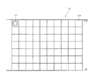
給電ボード22は、図6に示すように、水平方向及び垂直方向に区画された複数(図6では垂直方向に7ブロック×水平方向に10ブロック)の設置スペース22aを有しており、その何れかの設置スペース22aに給電部5を構成する給電コイルや給電コンデンサを有するユニットデバイス24を配置可能である。即ち、ユーザは受電側装置3の室内における設置位置に応じてユニットデバイス24を何れかの設置スペース22aに配置すれば良い。勿論、複数のユニットデバイス24を配置することも可能である。
As shown in FIG. 6, the
発光ボード23は、図7に示すように、給電ボード22に設けられている設置スペース22aに対応するように、水平方向及び垂直方向に区画された設置スペース23aを有しており、それぞれの設置スペース23aに報知部8を構成するLED25が配置されている。この場合、図8に示すように、受電側装置3としての例えばテレビを設置する部位に対応する発光ボード23の設置スペース23aにユニットデバイス24を配置し、ユニットデバイス24から受電側装置3に給電すると、その電力の出力に応じてLED25の点灯色が変化する。即ち、電力の出力が最も大きいエリアである受電側装置3の後方では危険エリアであることを示すようにLED25が例えば赤点灯する。又、危険エリアの周囲(受電側装置3から遠ざかる方)では注意エリアであることを示すようにLED25が例えば黄点灯する。更に、注意エリアの周囲(受電側装置3から遠ざかる方)では安全エリアであることを示すようにLED25が例えば緑点灯する。
As shown in FIG. 7, the
上記したユニットデバイス24を設置する態様として、図9に示すように、壁面に沿って水平方向に往復移動可能な移動ユニット31を設けても良い。移動ユニット31は、ガイド32aを有する天井側フレーム32、中間フレーム33、車輪34aを有する床側フレーム34、垂直フレーム35及び36、1対の垂直方向ガイドレール37、1対の水平方向ガイドレール38及び39、デバイス支持部材40及び41が組み合わされて構成されている。ユニットデバイス24がデバイス支持部材40又は41に装着された状態で、デバイス支持部材40又は41が水平方向ガイドレール38又は39に沿って水平方向に移動され、水平方向ガイドレール38又は39が垂直方向ガイドレール37に沿って垂直方向に移動されることで、ユニットデバイス24が位置決めされる。
As an aspect in which the above-described
以上に説明したように本実施形態によれば、給電側装置2の給電部5から受電側装置3の受電部10に給電する際の給電エリアに対してユーザがどの位置であるかを検知し、その検知した位置に応じて給電に関する情報(安全位置、注意位置、危険位置の何れかであるか)を報知させるようにした。これにより、ユーザが給電エリア内にいれば、放射暴露の可能性が高く、一方、ユーザが給電エリア外にいれば、放射暴露の可能性が低いことを報知することができ、給電に関する情報をユーザに対して適切に教示することができ、放射曝露等の問題を未然に回避することができる。
As described above, according to this embodiment, the position of the user relative to the power supply area when power is supplied from the
又、ユーザが例えば安全位置から危険位置に移動すると、給電を終了させるようにしたので、給電を継続させることによる悪影響の発生を未然に回避することができる。そして、給電を終了させた後に、ユーザが例えば危険位置から安全位置に移動すると、給電を再開させるようにすれば、給電を終了させる前の状態に速やかに復帰することができる。 In addition, when the user moves from the safe position to the dangerous position, for example, the power supply is terminated, so that it is possible to avoid an adverse effect caused by continuing the power supply. Then, after the power supply is finished, for example, when the user moves from the dangerous position to the safe position, if the power supply is resumed, it is possible to quickly return to the state before the power supply is finished.
又、ユーザが例えば安全位置から危険位置に移動すると、電力の出力を低下させ、電力の出力を低下させた後に、ユーザが例えば危険位置から安全位置に移動すると、電力の出力を復帰させるようにしても、同様の作用効果を得ることができる。 For example, when the user moves from the safe position to the dangerous position, the power output is decreased. After the power output is decreased, for example, when the user moves from the dangerous position to the safe position, the power output is restored. However, the same effect can be obtained.
又、給電を終了させたり電力の出力を低下させたりした場合に、補助電源11の使用を開始させ、給電を再開させたり電力の出力を復帰させたりした場合に、補助電源11の使用を終了させるようにすれば、放射曝露等の問題を未然に回避しつつ、受電側装置3の動作を継続させることができる。
In addition, when the power supply is terminated or the power output is reduced, the use of the auxiliary power supply 11 is started, and when the power supply is resumed or the power output is restored, the use of the auxiliary power supply 11 is terminated. By doing so, it is possible to continue the operation of the
本発明は、上記した実施形態にのみ限定されるものではなく、以下のように変形又は拡張することができる。
住宅内に設置する構成に限らず、車内に設置するようにしても良い。例えば車内に設置可能で且つ携帯情報端末や携帯電話機等の携帯機器を無線給電により充電可能な充電ホルダにおいて、充電ホルダから携帯機器への給電に関する情報を報知させるようにしても良い。
ユーザを検知対象とすることに限らず、動物(ペット)等を検知対象としても良い。
給電に関する情報を報知する態様としては、視覚的に報知する態様や聴覚的に報知する態様に限らず、例えば振動等を利用して触覚的に報知する態様であっても良い。
受電側装置3において、給電側装置2から受電して動作しているか補助電源11からの電力で動作しているかをユーザに対して教示しても良い。
給電側装置2を住宅側に設置し、受電側装置3を電気自動車側に設置し、住宅設備から電気自動車に給電するシステムに適用しても良い。
The present invention is not limited to the above-described embodiment, and can be modified or expanded as follows.
The configuration is not limited to being installed in a house, and may be installed in a vehicle. For example, in a charging holder that can be installed in a vehicle and can charge a portable device such as a portable information terminal or a mobile phone by wireless power feeding, information regarding power feeding from the charging holder to the portable device may be notified.
The detection target is not limited to the user, but an animal (pet) or the like may be the detection target.
A mode for notifying information related to power feeding is not limited to a mode for visually reporting or a mode for notifying audibly, and may be a mode for tactile reporting using, for example, vibration.
In the power receiving
You may apply to the system which installs the electric power feeding
図面中、1は無線給電システム、2は給電側装置、3は受電側装置、4は給電制御部(制御手段)、5は給電部(給電手段)、6は給電エリア記憶部(給電エリア記憶手段)、7は物体位置検知部(物体位置検知手段)、8は報知部(報知手段)、10は受電部(受電手段)、11は補助電源である。 In the drawings, 1 is a wireless power feeding system, 2 is a power feeding side device, 3 is a power receiving side device, 4 is a power feeding control unit (control unit), 5 is a power feeding unit (power feeding unit), and 6 is a power feeding area storage unit (power feeding area storage). Means), 7 is an object position detection unit (object position detection unit), 8 is a notification unit (notification unit), 10 is a power reception unit (power reception unit), and 11 is an auxiliary power source.
Claims (7)
前記給電手段(5)から前記受電手段(10)への給電エリアを記憶する給電エリア記憶手段(6)と、
物体の位置を検知する物体位置検知手段(7)と、
報知情報を報知する報知手段(8)と、
前記給電エリア記憶手段(6)に記憶されている給電エリア及び前記物体位置検知手段(7)による物体の位置の検知結果に応じて、前記給電手段(5)から前記受電手段(10)への給電に関する情報として、少なくとも前記給電手段(5)から前記受電手段(10)への給電の際に伝送される電力の出力に応じて放射暴露の可能性があることを示す危険エリアの位置が含まれる情報を前記報知手段(8)から報知させる制御手段(4)と、を備えたことを特徴とする無線給電システム。 A power supply side device (2) having power supply means (5) for supplying power wirelessly; and a power reception side device (3) having power reception means (10) for receiving power from the power supply means (5). In the wireless power supply system,
A power supply area storage means (6) for storing a power supply area from the power supply means (5) to the power receiving means (10);
An object position detecting means (7) for detecting the position of the object;
A notification means (8) for notifying the notification information;
Depending on the power supply area stored in the power supply area storage means (6) and the detection result of the object position by the object position detection means (7), the power supply means (5) to the power reception means (10). Information on power supply includes at least the position of a danger area indicating that there is a possibility of radiation exposure according to the output of power transmitted during power supply from the power supply means (5) to the power reception means (10). And a control means (4) for informing the information to be notified from the notification means (8).
前記制御手段(4)は、前記給電エリア記憶手段(6)に記憶されている給電エリア及び前記物体位置検知手段(7)による物体の位置の検知結果に応じて、給電を終了すべきと判定した場合には、前記給電手段(5)から前記受電手段(10)への給電を終了させることを特徴とする無線給電システム。 In the wireless power feeding system according to claim 1,
The control means (4) determines that the power supply should be terminated according to the power supply area stored in the power supply area storage means (6) and the detection result of the object position by the object position detection means (7). In this case, the wireless power feeding system ends power feeding from the power feeding means (5) to the power receiving means (10).
前記制御手段(4)は、前記給電手段(5)から前記受電手段(10)への給電を終了させた後に、前記給電エリア記憶手段(6)に記憶されている給電エリア及び前記物体位置検知手段(7)による物体の位置の検知結果に応じて、給電を再開すべきと判定した場合には、前記給電手段(5)から前記受電手段(10)への給電を再開させることを特徴とする無線給電システム。 In the wireless power feeding system according to claim 2,
The control means (4) detects the power supply area and the object position stored in the power supply area storage means (6) after finishing the power supply from the power supply means (5) to the power receiving means (10). The power supply from the power supply means (5) to the power reception means (10) is resumed when it is determined that the power supply should be restarted according to the detection result of the position of the object by the means (7). Wireless power supply system.
前記制御手段(4)は、前記給電エリア記憶手段(6)に記憶されている給電エリア及び前記物体位置検知手段(7)による物体の位置の検知結果に応じて、電力の出力を低下すべきと判定した場合には、前記給電手段(5)から前記受電手段(10)への電力の出力を低下させることを特徴とする無線給電システム。 In the wireless power feeding system according to claim 1,
The control means (4) should reduce the power output in accordance with the power supply area stored in the power supply area storage means (6) and the object position detection result by the object position detection means (7). If it is determined, the wireless power feeding system reduces the output of power from the power feeding means (5) to the power receiving means (10).
前記制御手段(4)は、前記給電手段(5)から前記受電手段(10)への電力の出力を低下させた後に、前記給電エリア記憶手段(6)に記憶されている給電エリア及び前記物体位置検知手段(7)による物体の位置の検知結果に応じて、電力の出力を復帰すべきと判定した場合には、前記給電手段(5)から前記受電手段(10)への電力の出力を復帰させることを特徴とする無線給電システム。 In the wireless power feeding system according to claim 4,
The control means (4) reduces the power output from the power supply means (5) to the power reception means (10) and then stores the power supply area and the object stored in the power supply area storage means (6). When it is determined that the power output should be restored according to the detection result of the position of the object by the position detection means (7), the power output from the power supply means (5) to the power reception means (10) is A wireless power feeding system characterized by being restored.
前記受電側装置は、補助電源(11)の使用を制御する受電制御部(9)を有し、
前記受電制御部(9)は、前記給電エリア記憶手段(6)に記憶されている給電エリア及び前記物体位置検知手段(7)による物体の位置の検知結果に応じて、前記補助電源(11)の使用を開始すべきと判定した場合には、前記補助電源(11)の使用を開始させることを特徴とする無線給電システム。 In the wireless power feeding system according to any one of claims 1 to 5,
The power receiving side device has a power receiving control unit (9) for controlling use of the auxiliary power source (11) ,
The power reception control unit (9) includes the auxiliary power source (11) according to a power feeding area stored in the power feeding area storage unit (6) and a detection result of an object position by the object position detecting unit (7). When it is determined that the use of the auxiliary power supply should be started, the use of the auxiliary power supply (11) is started.
前記受電制御部(9)は、前記補助電源(11)の使用を開始させた後に、前記給電エリア記憶手段(6)に記憶されている給電エリア及び前記物体位置検知手段(7)による物体の位置の検知結果に応じて、前記補助電源(11)の使用を終了すべきと判定した場合には、前記補助電源(11)の使用を終了させることを特徴とする無線給電システム。 The wireless power feeding system according to claim 6,
The power reception control unit (9) starts using the auxiliary power supply (11), and then supplies the power supply area stored in the power supply area storage means (6) and the object position detection means (7). The wireless power feeding system, wherein when it is determined that the use of the auxiliary power source (11) should be terminated according to the position detection result, the use of the auxiliary power source (11) is terminated.
Priority Applications (3)
| Application Number | Priority Date | Filing Date | Title |
|---|---|---|---|
| JP2012202714A JP5958217B2 (en) | 2012-09-14 | 2012-09-14 | Wireless power supply system |
| PCT/JP2013/003989 WO2014041729A1 (en) | 2012-09-14 | 2013-06-26 | Wireless power supply system |
| US14/420,693 US9800058B2 (en) | 2012-09-14 | 2013-06-26 | Wireless power supply system |
Applications Claiming Priority (1)
| Application Number | Priority Date | Filing Date | Title |
|---|---|---|---|
| JP2012202714A JP5958217B2 (en) | 2012-09-14 | 2012-09-14 | Wireless power supply system |
Publications (3)
| Publication Number | Publication Date |
|---|---|
| JP2014060822A JP2014060822A (en) | 2014-04-03 |
| JP2014060822A5 JP2014060822A5 (en) | 2015-01-22 |
| JP5958217B2 true JP5958217B2 (en) | 2016-07-27 |
Family
ID=50277876
Family Applications (1)
| Application Number | Title | Priority Date | Filing Date |
|---|---|---|---|
| JP2012202714A Expired - Fee Related JP5958217B2 (en) | 2012-09-14 | 2012-09-14 | Wireless power supply system |
Country Status (3)
| Country | Link |
|---|---|
| US (1) | US9800058B2 (en) |
| JP (1) | JP5958217B2 (en) |
| WO (1) | WO2014041729A1 (en) |
Families Citing this family (8)
| Publication number | Priority date | Publication date | Assignee | Title |
|---|---|---|---|---|
| JP6075118B2 (en) | 2013-02-28 | 2017-02-08 | 株式会社デンソー | Wireless power supply information provision system |
| JP6367166B2 (en) | 2015-09-01 | 2018-08-01 | 株式会社東芝 | Electronic apparatus and method |
| JP6809118B2 (en) | 2016-10-13 | 2021-01-06 | 富士ゼロックス株式会社 | Electronic devices, power supply devices and wireless power supply systems |
| JP6883423B2 (en) * | 2016-12-28 | 2021-06-09 | 株式会社Lixil | Equipment equipment |
| KR102464384B1 (en) * | 2017-10-20 | 2022-11-08 | 삼성전자주식회사 | Wireless power transmitter and method for controlling thereof |
| JP2022025563A (en) * | 2020-07-29 | 2022-02-10 | Tdk株式会社 | Power transmission device, wireless power transmission system, and information communication system |
| US20220171045A1 (en) * | 2020-12-01 | 2022-06-02 | Energous Corporation | Systems and methods for using one or more sensors to detect and classify objects in a keep-out zone of a wireless-power transmission field, and antennas with integrated sensor arrangements |
| US11916398B2 (en) | 2021-12-29 | 2024-02-27 | Energous Corporation | Small form-factor devices with integrated and modular harvesting receivers, and shelving-mounted wireless-power transmitters for use therewith |
Family Cites Families (7)
| Publication number | Priority date | Publication date | Assignee | Title |
|---|---|---|---|---|
| US8855554B2 (en) | 2008-03-05 | 2014-10-07 | Qualcomm Incorporated | Packaging and details of a wireless power device |
| US9178387B2 (en) | 2008-05-13 | 2015-11-03 | Qualcomm Incorporated | Receive antenna for wireless power transfer |
| JP2010017041A (en) * | 2008-07-06 | 2010-01-21 | Kyokko Denki Kk | Power supply apparatus |
| JP5515701B2 (en) * | 2009-12-04 | 2014-06-11 | ソニー株式会社 | Power transmission device, power reception device, and power transmission control method |
| JP5476211B2 (en) | 2010-05-19 | 2014-04-23 | Necトーキン株式会社 | Power transmission device, power receiving device, non-contact power transmission and communication system |
| JP2012019666A (en) | 2010-07-09 | 2012-01-26 | Sony Corp | Wireless charging device and wireless charging system |
| JP5740200B2 (en) * | 2011-04-22 | 2015-06-24 | 矢崎総業株式会社 | Resonant non-contact power feeding system, power receiving side device, and power transmitting side device |
-
2012
- 2012-09-14 JP JP2012202714A patent/JP5958217B2/en not_active Expired - Fee Related
-
2013
- 2013-06-26 WO PCT/JP2013/003989 patent/WO2014041729A1/en active Application Filing
- 2013-06-26 US US14/420,693 patent/US9800058B2/en not_active Expired - Fee Related
Also Published As
| Publication number | Publication date |
|---|---|
| US20150236515A1 (en) | 2015-08-20 |
| JP2014060822A (en) | 2014-04-03 |
| WO2014041729A1 (en) | 2014-03-20 |
| US9800058B2 (en) | 2017-10-24 |
Similar Documents
| Publication | Publication Date | Title |
|---|---|---|
| JP5958217B2 (en) | Wireless power supply system | |
| JP7026646B2 (en) | A wireless power transmission control method in a resonance type wireless power transmission system, a wireless power transmission device using the same, and a wireless power receiving device using the same. | |
| JP6411166B2 (en) | Wireless charging control method according to smart key position | |
| US9660480B2 (en) | Wireless charging method and electronic device implementing the same | |
| JP2013162624A (en) | Power supply system | |
| EP3081134A1 (en) | Robot cleaner | |
| KR102078073B1 (en) | Power supply apparatus | |
| JP6418867B2 (en) | Power supply device | |
| JP2016010070A (en) | Mobile apparatus and control method thereof | |
| JP2009261105A (en) | Radio energy transmission device and radio energy transmission method | |
| KR20180115207A (en) | Wireless power transmitting device, electronic device for wirelessly receiving power and operation method thereof | |
| US10027156B2 (en) | Electronic apparatus and charging method | |
| JP6060516B2 (en) | Electronic equipment and power supply system | |
| JP5280506B2 (en) | Electric equipment charging and anti-theft system in product order system | |
| US9373244B2 (en) | Base and display device having a sensing component for detecting a remote controller | |
| JP6198440B2 (en) | Wireless power transmission apparatus, control method for wireless power transmission apparatus, and program | |
| KR20210073419A (en) | Mobile robot operation service system | |
| JP2014057472A (en) | Non-contact power transmission device and power transmitter using the same and power receiver | |
| JP6677520B2 (en) | Information processing apparatus, control method, and program | |
| JP2013257812A (en) | Portable terminal device and program | |
| KR101521905B1 (en) | System, apparatus and method for notifying location of object | |
| JP5766147B2 (en) | Electronic device and operation display device | |
| JP7460908B2 (en) | Mobile devices | |
| JP2001197674A (en) | Rechargeable wireless receiver | |
| JP5705159B2 (en) | Electronic device and operation display device |
Legal Events
| Date | Code | Title | Description |
|---|---|---|---|
| A521 | Request for written amendment filed |
Free format text: JAPANESE INTERMEDIATE CODE: A523 Effective date: 20141127 |
|
| A621 | Written request for application examination |
Free format text: JAPANESE INTERMEDIATE CODE: A621 Effective date: 20150327 |
|
| TRDD | Decision of grant or rejection written | ||
| A01 | Written decision to grant a patent or to grant a registration (utility model) |
Free format text: JAPANESE INTERMEDIATE CODE: A01 Effective date: 20160524 |
|
| A61 | First payment of annual fees (during grant procedure) |
Free format text: JAPANESE INTERMEDIATE CODE: A61 Effective date: 20160606 |
|
| R151 | Written notification of patent or utility model registration |
Ref document number: 5958217 Country of ref document: JP Free format text: JAPANESE INTERMEDIATE CODE: R151 |
|
| R250 | Receipt of annual fees |
Free format text: JAPANESE INTERMEDIATE CODE: R250 |
|
| LAPS | Cancellation because of no payment of annual fees |