JP5951571B2 - Heat transfer medium device and air conditioning system for heat absorption of automobile - Google Patents
Heat transfer medium device and air conditioning system for heat absorption of automobile Download PDFInfo
- Publication number
- JP5951571B2 JP5951571B2 JP2013195621A JP2013195621A JP5951571B2 JP 5951571 B2 JP5951571 B2 JP 5951571B2 JP 2013195621 A JP2013195621 A JP 2013195621A JP 2013195621 A JP2013195621 A JP 2013195621A JP 5951571 B2 JP5951571 B2 JP 5951571B2
- Authority
- JP
- Japan
- Prior art keywords
- air
- flow
- mass flow
- evaporator
- air mass
- Prior art date
- Legal status (The legal status is an assumption and is not a legal conclusion. Google has not performed a legal analysis and makes no representation as to the accuracy of the status listed.)
- Active
Links
Images


Classifications
-
- B—PERFORMING OPERATIONS; TRANSPORTING
- B60—VEHICLES IN GENERAL
- B60H—ARRANGEMENTS OF HEATING, COOLING, VENTILATING OR OTHER AIR-TREATING DEVICES SPECIALLY ADAPTED FOR PASSENGER OR GOODS SPACES OF VEHICLES
- B60H1/00—Heating, cooling or ventilating [HVAC] devices
- B60H1/00007—Combined heating, ventilating, or cooling devices
- B60H1/00021—Air flow details of HVAC devices
- B60H1/00035—Air flow details of HVAC devices for sending an air stream of uniform temperature into the passenger compartment
- B60H1/0005—Air flow details of HVAC devices for sending an air stream of uniform temperature into the passenger compartment the air being firstly cooled and subsequently heated or vice versa
-
- B—PERFORMING OPERATIONS; TRANSPORTING
- B60—VEHICLES IN GENERAL
- B60H—ARRANGEMENTS OF HEATING, COOLING, VENTILATING OR OTHER AIR-TREATING DEVICES SPECIALLY ADAPTED FOR PASSENGER OR GOODS SPACES OF VEHICLES
- B60H1/00—Heating, cooling or ventilating [HVAC] devices
- B60H1/00007—Combined heating, ventilating, or cooling devices
- B60H1/00021—Air flow details of HVAC devices
- B60H1/00035—Air flow details of HVAC devices for sending an air stream of uniform temperature into the passenger compartment
- B60H1/00057—Air flow details of HVAC devices for sending an air stream of uniform temperature into the passenger compartment the air being heated and cooled simultaneously, e.g. using parallel heat exchangers
-
- B—PERFORMING OPERATIONS; TRANSPORTING
- B60—VEHICLES IN GENERAL
- B60H—ARRANGEMENTS OF HEATING, COOLING, VENTILATING OR OTHER AIR-TREATING DEVICES SPECIALLY ADAPTED FOR PASSENGER OR GOODS SPACES OF VEHICLES
- B60H1/00—Heating, cooling or ventilating [HVAC] devices
- B60H1/00007—Combined heating, ventilating, or cooling devices
- B60H1/00021—Air flow details of HVAC devices
- B60H2001/00078—Assembling, manufacturing or layout details
- B60H2001/00085—Assembling, manufacturing or layout details of air intake
-
- B—PERFORMING OPERATIONS; TRANSPORTING
- B60—VEHICLES IN GENERAL
- B60H—ARRANGEMENTS OF HEATING, COOLING, VENTILATING OR OTHER AIR-TREATING DEVICES SPECIALLY ADAPTED FOR PASSENGER OR GOODS SPACES OF VEHICLES
- B60H1/00—Heating, cooling or ventilating [HVAC] devices
- B60H1/00007—Combined heating, ventilating, or cooling devices
- B60H1/00021—Air flow details of HVAC devices
- B60H2001/00114—Heating or cooling details
- B60H2001/00135—Deviding walls for separate air flows
-
- B—PERFORMING OPERATIONS; TRANSPORTING
- B60—VEHICLES IN GENERAL
- B60H—ARRANGEMENTS OF HEATING, COOLING, VENTILATING OR OTHER AIR-TREATING DEVICES SPECIALLY ADAPTED FOR PASSENGER OR GOODS SPACES OF VEHICLES
- B60H1/00—Heating, cooling or ventilating [HVAC] devices
- B60H1/00007—Combined heating, ventilating, or cooling devices
- B60H1/00021—Air flow details of HVAC devices
- B60H2001/0015—Temperature regulation
- B60H2001/00178—Temperature regulation comprising an air passage from the HVAC box to the exterior of the cabin
Landscapes
- Physics & Mathematics (AREA)
- Thermal Sciences (AREA)
- Engineering & Computer Science (AREA)
- Mechanical Engineering (AREA)
- Air-Conditioning For Vehicles (AREA)
Description
本発明は、ブロワと、空気案内部と、熱伝達媒体と、を有する空気冷却用の熱伝達媒体装置に関する。熱伝達媒体は、冷媒回路に一体化され、冷媒によって貫流可能であり、また熱を空気から冷媒に伝達可能であるように空気で付勢可能に形成され、冷媒が蒸発する。 The present invention relates to an air cooling heat transfer medium device having a blower, an air guide, and a heat transfer medium. The heat transfer medium is integrated into the refrigerant circuit, can flow through the refrigerant, and can be energized with air so that heat can be transferred from the air to the refrigerant, and the refrigerant evaporates.
本発明は、さらに、熱伝達媒体装置を有する自動車の乗員室の空気を調和させるための空調システムに関する。空調システムは、空気を導くための第1及び第2の流れダクトを有するハウジングと、熱伝達媒体装置の熱伝達媒体に対応する第1の熱伝達媒体、圧縮機、第2の熱伝達媒体及び膨張器を有する冷媒回路とを備える。第1の熱伝達媒体は第1の流れダクトに配置され、第2の熱伝達媒体は第2の流れダクトに配置される。 The invention further relates to an air conditioning system for conditioning the air in the passenger compartment of a motor vehicle having a heat transfer medium device. The air conditioning system includes a housing having first and second flow ducts for guiding air, a first heat transfer medium corresponding to the heat transfer medium of the heat transfer medium device, a compressor, a second heat transfer medium, and And a refrigerant circuit having an expander. The first heat transfer medium is disposed in the first flow duct and the second heat transfer medium is disposed in the second flow duct.
さらに、本発明は、冷凍システム運転及び加熱運転の組み合わせ用、並びに、後加熱運転で乗員室の空気を調和させるための後加熱運転用の空調システムを運転する方法、並びに、蒸発器として運転される熱伝達媒体の凍結を検出して防止するための方法に関する。 Further, the present invention is operated as a method for operating an air conditioning system for a combination of a refrigeration system operation and a heating operation, and a post-heating operation for harmonizing passenger compartment air in the post-heating operation, and an evaporator. The present invention relates to a method for detecting and preventing freezing of a heat transfer medium.
長い間、従来技術に属する自動車用の空調システムは、様々な個別の構成要素を有する冷媒回路、例えば従来車両前部に配置された凝縮器と、車両エンジンに結合され且つこれによって駆動される圧縮機と、乗員室に配置された蒸発器並びにホース及び結合部とを備える。空調システムは空気を調和させ、次にこの空気が乗員室内に導かれる。圧縮機は、通常、機械的エネルギを圧縮機シャフトに結合することにより自動車のエンジンによって駆動される。クーラファン及びブロワには車両回路から12Vの電気が供給される。 For a long time, the automotive air conditioning systems belonging to the prior art have been connected to and driven by refrigerant circuits having various individual components, such as a condenser located in the front of a conventional vehicle and a vehicle engine. And an evaporator disposed in the passenger compartment, as well as a hose and a joint. The air conditioning system harmonizes the air, which is then directed into the passenger compartment. The compressor is typically driven by an automobile engine by coupling mechanical energy to the compressor shaft. The cooler fan and blower are supplied with 12V electricity from the vehicle circuit.
乗員室用の送風はブロワを介して空調ユニットに吸引され、冷却及び/又は除湿のために冷媒回路の蒸発器を介して導かれる。高い圧力レベルの凝縮器の冷凍モードにおける空調システムの運転時、圧縮機で圧縮された蒸気状の冷媒から熱が抽出され、周囲空気に放出される。 The air for the passenger compartment is sucked into the air conditioning unit through the blower and guided through the evaporator of the refrigerant circuit for cooling and / or dehumidification. During operation of the air conditioning system in the high pressure level condenser refrigeration mode, heat is extracted from the vapor refrigerant compressed by the compressor and released to the ambient air.
自動車の前部領域の取付け位置において、凝縮器は空気の流れ方向に対して垂直に位置し、たいてい大きな網面を利用し、この網面は、小型自動車の場合、14dm2〜18dm2の範囲の値を有し、コンパクトクラスの自動車の場合、20dm2〜22dm2の範囲の値を有し、より大型の自動車の場合、24dm2を超える値を有する。
At the mounting position in the front region of the car, the condenser is positioned perpendicular to the direction of air flow and usually uses a large mesh surface, which in the case of a small car is in the range of 14
網面とは、熱伝達媒体の入口もしくは出口に空気の流れ方向に対してほぼ垂直に向けられた面であると理解すべきであり、これは流れ面とも呼ばれる。この場合、網面は、熱伝達媒体のリブ状のもしくはリブで形成された領域を含み、空気側の流れ断面に対応する。 A mesh surface is to be understood as a surface oriented substantially perpendicular to the direction of air flow at the inlet or outlet of the heat transfer medium, which is also called the flow surface. In this case, the mesh surface includes a rib-like or rib-shaped region of the heat transfer medium and corresponds to the air-side flow cross section.
熱伝達媒体によって周囲空気を搬送するために、アキシャルファンとして形成されたクーラファンが使用され、このクーラファンが吸引ファンとして、いわゆるクーラモジュールの空気側出口に配置される。アキシャルファンは、圧力差が小さくても大きな空気体積流を搬送するので、空気側に直列に前後に配置され且つ貫流される冷凍モジュールの熱伝達媒体、例えば、エンジン冷却回路の冷却液−空気熱伝達媒体、給気冷却器、及び冷媒回路の凝縮器は、空気の流れ抵抗を低減するために、可能な限り小さな深さで形成される。この場合、深さとは、空気の流れ方向の熱伝達媒体の厚さもしくは空気側の流れの長さであると理解すべきである。 In order to convey the ambient air by means of a heat transfer medium, a cooler fan formed as an axial fan is used and this cooler fan is arranged as a suction fan at the air side outlet of the so-called cooler module. An axial fan conveys a large volume of air flow even if the pressure difference is small, so that the heat transfer medium of the refrigeration module that is arranged in front and back in series on the air side and flows through, for example, the coolant-air heat of the engine cooling circuit The transmission medium, the charge air cooler, and the condenser of the refrigerant circuit are formed with as little depth as possible to reduce the air flow resistance. In this case, the depth should be understood as the thickness of the heat transfer medium in the direction of air flow or the length of the air-side flow.
従来技術では、ヒートポンプモード及び熱源としての周囲空気による運転を伴う自動車用の空調システムの場合、冷凍モードで凝縮器として運転される熱伝達媒体が蒸発器として使用される。 In the prior art, in the case of an air conditioning system for an automobile that involves operation with a heat pump mode and ambient air as a heat source, a heat transfer medium that operates as a condenser in a refrigeration mode is used as an evaporator.
冷凍モードにおいて熱が冷媒から周囲空気に放出され、並びにヒートポンプモードにおいて熱が周囲空気から吸収される熱伝達媒体の運転の場合、周囲空気はクーラファン又はクーラファンパケットを介して熱伝達媒体によって吸引される。車速に基づく追加の空気速度なしに、すなわち、車両の停止状態において、クーラファンの最大出力時に、最高3.5m/sのほんの小さな空気の平均流れ速度が達成される。 In the case of operation of a heat transfer medium where heat is released from the refrigerant to the ambient air in the refrigeration mode and heat is absorbed from the ambient air in the heat pump mode, the ambient air is sucked by the heat transfer medium via the cooler fan or cooler fan packet Is done. A small average air flow speed of up to 3.5 m / s is achieved without additional air speed based on vehicle speed, i.e. when the vehicle is stationary, at the maximum output of the cooler fan.
しかしながら、空気の流速は、熱伝達媒体の凍結なしに周囲空気から吸収可能な出力に、従って、熱源としての周囲空気を有するヒートポンプの加熱出力に大きな影響を及ぼす。
熱伝達媒体の後の空気の流れ方向におけるクーラファンの先行技術から公知の配置によって、クーラファンの駆動に生じる損失熱がさらに利用不能である。
However, the air flow rate has a significant effect on the power that can be absorbed from the ambient air without freezing the heat transfer medium, and thus on the heating output of a heat pump with ambient air as a heat source.
Due to the arrangement known from the prior art of the cooler fan in the direction of air flow after the heat transfer medium, the heat loss generated in driving the cooler fan is further unavailable.
従来、冷凍モードで蒸発器として運転される熱伝達媒体には、600kg/hよりも小さな空気量が加えられる。これに対して、冷凍モードで凝縮器として及びヒートポンプモードで蒸発器として運転される熱伝達媒体には、1800kg/hよりも明らかに大きな空気量が貫流される。 Conventionally, an air amount smaller than 600 kg / h is applied to a heat transfer medium operated as an evaporator in a refrigeration mode. On the other hand, an air amount clearly larger than 1800 kg / h flows through the heat transfer medium operated as a condenser in the refrigeration mode and as an evaporator in the heat pump mode.
従来技術から、蒸発器が冷凍モード及びヒートポンプモードの両方で蒸発器として運転され、同様に、凝縮器が冷凍モード及びヒートポンプモードの両方で凝縮器として運転されるヒートポンプ機能を有する空調システムも知られている。この場合、熱流の制御は空気側の流れガイドを介して完全に実現される。 From the prior art, there is also known an air conditioning system having a heat pump function in which the evaporator is operated as an evaporator in both the refrigeration mode and the heat pump mode, and similarly, the condenser is operated as a condenser in both the refrigeration mode and the heat pump mode. ing. In this case, the control of the heat flow is completely realized via the air-side flow guide.
特許文献1(仏国特許出願公開第2743027号明細書)から、蒸発器、圧縮機、凝縮器及び膨張器のみを備える従来の冷媒回路を有する車両空調システムが知られている。熱伝達媒体は、互いに少なくとも流動技術的に分離して形成された別個の流れダクトに配置される。流れダクトは交差結合部又はバイパスを含む。ブロワによって吸引された空気質量流は、フラップを開閉することにより並びに必要及び運転モードに応じてバイパスを通して貫通して導くことにより熱伝達媒体の面を介して導かれる。この場合、空気質量流は、冷却及び/又は除湿もしくは加温され、次に、乗員室及び/又は周囲に排出される。 From Patent Document 1 (French Patent Application Publication No. 2743027), a vehicle air conditioning system having a conventional refrigerant circuit having only an evaporator, a compressor, a condenser and an expander is known. The heat transfer medium is arranged in separate flow ducts which are formed at least in a flow-technical manner. The flow duct includes a cross-connect or bypass. The air mass flow drawn by the blower is directed through the face of the heat transfer medium by opening and closing the flaps and directing through the bypass as required and operating mode. In this case, the air mass flow is cooled and / or dehumidified or warmed and then discharged into the passenger compartment and / or the surroundings.
特許文献2(独国特許出願公開第102011052752号明細書)には、空気を加熱及び冷却するためのモジュール式の車両空調システムが記載されている。車両空調システムは、ブロワと空気流れ経路を調整するためのフラップとを有するハウジングと、凝縮器と蒸発器と圧縮機と膨張器と付属の結合ラインとを有する冷媒回路とを備える。ハウジングには、一体化された蒸発器を有する蒸発器−空気流れ経路、及び一体化された凝縮器を有する凝縮器−空気流れ経路が形成される。各空気流れ経路には、周囲からの新気、乗員室からの循環内気、又は新気及び循環内気の両方からの混合気を加えることが可能である。空気の流れ経路の調整のみによって乗員室の加熱又は冷却が行われるように、両方の空気流れ経路が、制御可能なフラップを介して互いに結合される。 Patent Document 2 (German Patent Application Publication No. 102011052752) describes a modular vehicle air conditioning system for heating and cooling air. The vehicle air conditioning system includes a housing having a blower and a flap for adjusting an air flow path, and a refrigerant circuit having a condenser, an evaporator, a compressor, an expander, and an associated coupling line. The housing is formed with an evaporator-air flow path with an integrated evaporator and a condenser-air flow path with an integrated condenser. It is possible to add fresh air from the surroundings, circulating air from the passenger compartment, or air-fuel mixture from both fresh air and circulating air to each air flow path. Both air flow paths are connected to each other via a controllable flap so that the passenger compartment is heated or cooled only by adjusting the air flow path.
さらに、従来技術から、ヒートポンプモードの運転時に蒸発器の凍結を防止するための調節方法が知られている。この場合、周囲温度に基づく蒸発器の消費電力は、例えば、温度レベルを介してもしくは冷媒の蒸発圧力を介して制限される。 Furthermore, an adjustment method for preventing the evaporator from freezing during operation in the heat pump mode is known from the prior art. In this case, the power consumption of the evaporator based on the ambient temperature is limited, for example, via the temperature level or via the evaporation pressure of the refrigerant.
特許文献3(独国特許出願公開第102011051285号明細書)は、車両の空調システムのヒートポンプの蒸発器の凍結防止を調節するための方法及び装置を開示している。乗員室は、液体冷媒を蒸発させるための熱源として周囲空気を利用する蒸発器を備えるヒートポンプを用いて加熱される。周囲空気の表面温度速度は、蒸発器の前の周囲空気の温度に基づき、凍結防止を調節するための装置を用いて調節される。調節のために、蒸発器の表面温度が、蒸発器の出口と圧縮機の入口との間の冷媒ラインの部分で測定された冷媒ラインに流れる冷媒の圧力及び温度に関する信号を用いて評価又は算出され、車両の前に存在する周囲空気の露点が計算され、周囲空気の流速及び蒸発器表面の温度レベルが、膨張器の開口断面積、冷媒ラインの冷媒質量流、及びファンの回転数、並びに圧縮機に基づく行程又は圧縮機の回転数を用いて調整される。さらに、蒸発器には、蒸発器の局所的な凍結を防止するために最小の過熱が予め設定される。
Patent document 3 (
本発明の課題は、空気を冷却するための熱伝達媒体装置であって、熱伝達媒体を通して流れる冷媒によって空気から効率的に熱が抽出されるべきであり、且つ空気搬送装置の廃熱が熱源として利用可能である熱伝達媒体装置をさらに発展させることである。 An object of the present invention is a heat transfer medium device for cooling air, in which heat should be efficiently extracted from the air by a refrigerant flowing through the heat transfer medium, and waste heat of the air transfer device is a heat source Further development of a heat transfer medium device that can be used as:
本発明の別の課題は、特に自動車に使用するための加熱機能を有する空調システムを提供することにある。空調システムの冷媒回路は最小数の構成要素のみにより、従って、安価で保守が少なく形成されるべきである。さらに、空調システムは、冷凍システム運転及びヒートポンプ運転の組み合わせ用に、並びに乗員室の調和されるべき空気を加熱、冷却及び除湿するための後加熱運転用に構成されるべきであろう。この場合、運転は、低い容量の熱源を有する周囲においても、例えば、エネルギ効率的な内燃機関又は内燃機関と電動機とからなるハイブリッド駆動装置の場合、もしくは駆動装置からの熱源が存在しない場合、例えば、電気的に駆動される自動車の場合、乗員室内の快適な空調に対するすべての要求を満たすことが可能であるべきである。 Another object of the present invention is to provide an air conditioning system having a heating function particularly for use in an automobile. The refrigerant circuit of the air conditioning system should be formed with only a minimum number of components, and therefore inexpensive and less maintenance. In addition, the air conditioning system should be configured for a combination of refrigeration system operation and heat pump operation, and for post-heating operation to heat, cool and dehumidify the air to be conditioned in the passenger compartment. In this case, the operation is performed even in an environment having a low-capacity heat source, for example, in the case of an energy efficient internal combustion engine or a hybrid drive device composed of an internal combustion engine and an electric motor, or when there is no heat source from the drive device. In the case of electrically driven vehicles, it should be possible to meet all the requirements for comfortable air conditioning in the passenger compartment.
本発明の別の課題は、特に後加熱運転で効率的な運転が可能である空調システムを運転するための方法を提供することである。 Another object of the present invention is to provide a method for operating an air conditioning system that is capable of efficient operation, particularly in post-heating operation.
本発明の別の課題は、ヒートポンプモードの運転時に、蒸発器として運転される熱伝達媒体の凍結の開始を検出すること、及び/又は空調システムのヒートポンプ機能を連続的に維持するために凍結を防止することである。この場合、本方法は簡単且つ安価に実現可能であるべきである。 Another object of the present invention is to detect the start of freezing of the heat transfer medium operated as an evaporator during operation in the heat pump mode and / or to perform freezing to continuously maintain the heat pump function of the air conditioning system. Is to prevent. In this case, the method should be simple and inexpensive to implement.
上述した課題は、本発明によれば、ブロワと、空気案内部と、冷媒回路に一体化して配置された熱伝達媒体とを備える、空気を冷却するための熱伝達媒体装置によって解決される。熱伝達媒体は、一方で、冷媒によって貫流可能であり、他方で、熱を空気から冷媒に伝達可能であるように空気で付勢可能に形成される。冷媒は熱吸収時に蒸発される。 According to the present invention, the above-described problem is solved by a heat transfer medium device for cooling air, which includes a blower, an air guide, and a heat transfer medium arranged integrally with the refrigerant circuit. The heat transfer medium is formed on the one hand so as to be able to flow through by the refrigerant and on the other hand to be energized by air so that heat can be transferred from the air to the refrigerant. The refrigerant is evaporated during heat absorption.
空気案内部とは、例えば、空気が入口から出口まで導かれて調和される空調システムの流れダクトであると理解すべきである。 An air guide is to be understood as, for example, a flow duct of an air conditioning system in which air is guided and harmonized from the inlet to the outlet.
本発明の構想によれば、熱伝達媒体装置のブロワは、ブロワの損失熱が、空気が熱伝達媒体に達する前に空気を加温するように、空気の流れ方向に熱伝達媒体の前に配置される。熱伝達媒体は、本発明によれば、直列に配置された管を有する管熱伝達媒体として形成され、この場合、管熱伝達媒体は少なくとも2列に形成される。 According to the concept of the invention, the blower of the heat transfer medium device is arranged in front of the heat transfer medium in the direction of air flow so that the heat loss of the blower heats the air before the air reaches the heat transfer medium. Be placed. The heat transfer medium is formed according to the invention as a tube heat transfer medium having tubes arranged in series, in which case the tube heat transfer medium is formed in at least two rows.
ブロワの損失熱を、熱伝達媒体に供給されるべき空気に伝達することによって、空気質量流が約1K〜5Kだけ加温されることが有利である。 Advantageously, the air mass flow is heated by about 1K to 5K by transferring the heat loss of the blower to the air to be supplied to the heat transfer medium.
本発明の改良によれば、熱伝達媒体は、2dm2〜10dm2の範囲、好ましくは4dm2〜5dm2の範囲の流れ面を備える。この流れ面によって、熱伝達媒体は、それぞれ必要な出力を伝達するために、自動車の空調システムの冷凍システム運転及びヒートポンプ運転の両方で蒸発器として使用可能であり、この場合、空調システムの冷凍システムモードで凝縮器として及びヒートポンプモードで蒸発器として運転される従来技術から公知の熱伝達媒体よりも小さな流れ面を備える。 According to an improvement of the present invention, the heat transfer medium is in the range of 2dm 2 ~10dm 2, preferably comprises a flow surface in the range of 4dm 2 ~5dm 2. With this flow surface, the heat transfer medium can be used as an evaporator in both refrigeration system operation and heat pump operation of an automobile air conditioning system to transmit the required output respectively, in which case the refrigeration system of the air conditioning system It has a smaller flow surface than the heat transfer medium known from the prior art, operating as a condenser in mode and as an evaporator in heat pump mode.
第1の変形実施形態によれば、熱伝達媒体のすべての管列がそれぞれ単流で貫流される。この場合、管列は空気の流れ方向に対して垂直に整列されることが有利である。冷媒は、次の管列の管を通して導かれる前に、管列のすべての管を通して平行方向に流れる。このようにして、異なる管列の管は冷媒側で連続して、すなわち直列に貫流される。 According to the first variant embodiment, all the tube rows of the heat transfer medium are each flowed in a single flow. In this case, the tube rows are advantageously aligned perpendicular to the direction of air flow. The refrigerant flows in parallel through all the tubes of the tube row before being led through the tubes of the next tube row. In this way, the tubes of the different tube rows flow continuously on the refrigerant side, i.e. in series.
第2の変形実施形態によれば、熱伝達媒体は、複数の管列の少なくとも1つの列が複流で貫流されるように形成される。この場合、冷媒は管列のいくつかの管を通して第1の方向に導かれ、一方、冷媒は、同一の管列の他の管を通して、第1の方向とは反対方向に配置された第2の方向に流れる。冷媒は管列の管を通してそれぞれ平行に流れる。 According to the second variant embodiment, the heat transfer medium is formed such that at least one of the plurality of tube rows flows through in a double flow. In this case, the refrigerant is guided in the first direction through several tubes of the tube row, while the refrigerant is second through the other tubes in the same tube row and arranged in a direction opposite to the first direction. Flowing in the direction of. The refrigerant flows in parallel through the tubes in the tube row.
管列から次の管列への冷媒の貫流は、空気側の流れ方向に又はその反対方向にそれぞれ行うことができ、この結果、熱伝達媒体はクロスパラレルフロー熱伝達媒体として又はクロスカウンタカレントフロー熱伝達媒体として形成される。 The flow of refrigerant from one tube row to the next can be performed in the air-side flow direction or vice versa, so that the heat transfer medium can be a cross-parallel flow heat transfer medium or a cross-counter current flow. It is formed as a heat transfer medium.
熱伝達媒体は平型管から形成されることが有利であり、これらの平型管は、空気の流れ方向に対して垂直に整列され、それらの平坦な側面は空気の流れ方向に整列される。平型管は8mmよりも大きな幅を有する。この場合、平型管の幅は好ましくは11.5mm〜18mmの範囲にある。平型管は12.3mm又は16mmの幅で形成することが有利である。この場合、平型管の幅とは空気の流れ方向の管の延長部であると理解すべきである。 The heat transfer medium is advantageously formed from flat tubes, which are aligned perpendicular to the direction of air flow and their flat sides are aligned in the direction of air flow. . The flat tube has a width greater than 8 mm. In this case, the width of the flat tube is preferably in the range of 11.5 mm to 18 mm. The flat tube is advantageously formed with a width of 12.3 mm or 16 mm. In this case, the width of the flat tube should be understood as the extension of the tube in the direction of air flow.
熱伝達媒体の空気側はリブで形成されることが好ましい。この場合、リブは、1dm当たり100個未満のリブ密度で、好ましくは、1dm当たり70〜80個のリブ密度で配置されることが有利である。 The air side of the heat transfer medium is preferably formed with ribs. In this case, the ribs are advantageously arranged with a rib density of less than 100 per dm, preferably with a density of 70-80 ribs per dm.
システムに加熱機能を提供する課題は、既述の熱伝達媒体装置を有する自動車の乗員室の空気を調和させるための空調システムによって解決される。この場合、空調システムは、空気を導くための第1及び第2の流れダクトを有するハウジングと、蒸発器として形成された第1の熱伝達媒体、圧縮機、凝縮器として形成された第2の熱伝達媒体、及び膨張器を有する冷媒回路とを備える。第1の熱伝達媒体は第1の流れダクトに配置され、第2の熱伝達媒体は第2の流れダクトに配置される。この場合、第1の熱伝達媒体は、本発明による熱伝達媒体装置の熱伝達媒体に対応する。 The problem of providing a heating function to the system is solved by an air conditioning system for harmonizing the air in the passenger compartment of a motor vehicle having the heat transfer medium device described above. In this case, the air conditioning system includes a housing having first and second flow ducts for guiding air, a first heat transfer medium formed as an evaporator, a compressor, and a second formed as a condenser. A heat transfer medium and a refrigerant circuit having an expander. The first heat transfer medium is disposed in the first flow duct and the second heat transfer medium is disposed in the second flow duct. In this case, the first heat transfer medium corresponds to the heat transfer medium of the heat transfer medium device according to the present invention.
本発明の構想によれば、空調システムは、乗員室を冷却するための冷凍システム運転及び乗員室を加熱するためのヒートポンプ運転の組み合わせ用に、並びに、後加熱運転用に設計される。それぞれの運転モードの調整は、空調システムのハウジングの内部に配置された空気案内装置の制御のみを介して行われ、冷媒回路の調節を介せずに行われる。第1の熱伝達媒体は、本発明によれば、運転モードとは無関係に、運転モードでそれぞれ必要な出力が、熱伝達媒体面を介して導かれた空気質量流から冷媒に伝達可能であるように、空気質量流を冷却及び/又は除湿するための蒸発器として形成され且つ運転可能である。 According to the inventive concept, the air conditioning system is designed for a combination of a refrigeration system operation for cooling the passenger compartment and a heat pump operation for heating the passenger compartment, as well as for a post-heating operation. The adjustment of each operation mode is performed only through control of an air guide device disposed inside the housing of the air conditioning system, and is performed without adjustment of the refrigerant circuit. According to the present invention, the first heat transfer medium can transmit the output necessary for the operation mode to the refrigerant from the air mass flow guided through the heat transfer medium surface regardless of the operation mode. As such, it is configured and operable as an evaporator for cooling and / or dehumidifying the air mass flow.
蒸発器として形成された第1の熱伝達媒体は、冷凍システムモード及びヒートポンプモードの両方の運転時に、冷媒側及び空気側でそれぞれ同一の方向に貫流される。 The first heat transfer medium formed as an evaporator flows through in the same direction on the refrigerant side and the air side in both the refrigeration system mode and the heat pump mode.
第2の熱伝達媒体は運転モードとは無関係に、好ましくは凝縮器又はガス冷却器として形成され、空気質量流を加温するために運転される。 Regardless of the mode of operation, the second heat transfer medium is preferably formed as a condenser or a gas cooler and is operated to warm the air mass flow.
熱伝達媒体装置により、有利には、
−ヒートポンプモードにおいて、
−空気質量流を3.5m/sよりも高い空気速度、好ましくは約5m/sで蒸発器に搬送することができ、
−600kg/hを超える、好ましくは約1,000kg/hの空気質量流を蒸発器に搬送することができ、この蒸発器は、例えば、蒸発器内への空気入口温度が+10℃よりも低く、好ましくは0℃よりも低く、また出力が1kWを超えた場合に、10Kよりも低く、好ましくは5Kよりも低く、僅かにのみ冷却され、
−0.3kW〜6kWの範囲の出力を伝達することができ、この場合、例えば、周囲温度が−10℃である場合に、0.5kW〜6kWの範囲、好ましくは2kW〜3kWの範囲の出力が伝達可能であり、
−冷却システムモードにおいて、
−600kg/hよりも小さい、好ましくは約400kg/hの空気質量流を蒸発器に搬送することができ、この場合、2kWよりも高い出力が伝達可能であり、
−0.5kWよりも高い出力を伝達することができ、この場合、例えば、周囲温度が+30℃を超えた場合に、4kW〜8kWの範囲、好ましくは約6kWの出力が伝達可能である。
With the heat transfer medium device, advantageously
-In heat pump mode,
The air mass flow can be conveyed to the evaporator at an air velocity higher than 3.5 m / s, preferably about 5 m / s;
An air mass flow of greater than −600 kg / h, preferably about 1,000 kg / h, can be conveyed to the evaporator, for example when the air inlet temperature into the evaporator is lower than + 10 ° C. Preferably lower than 0 ° C. and lower than 10K, preferably lower than 5K, only slightly cooled when the output exceeds 1 kW,
An output in the range of −0.3 kW to 6 kW can be transmitted. In this case, for example, when the ambient temperature is −10 ° C., an output in the range of 0.5 kW to 6 kW, preferably in the range of 2 kW to 3 kW Can communicate,
-In the cooling system mode
An air mass flow of less than −600 kg / h, preferably about 400 kg / h can be conveyed to the evaporator, in which case an output higher than 2 kW can be transmitted;
An output higher than −0.5 kW can be transmitted. In this case, for example, when the ambient temperature exceeds + 30 ° C., an output in the range of 4 kW to 8 kW, preferably about 6 kW can be transmitted.
ヒートポンプ機能、すなわち、第1の空気質量流を冷却及び/又は除湿し、同時に第2の空気質量流を加温することを含む空調システムは、再加熱運転とも呼ばれる後加熱運転で運転可能であることが有利である。この場合、後加熱運転は、純粋な後加熱運転として、すなわち、調和されていない空気を混合することなく可能である。 An air conditioning system that includes a heat pump function, i.e., cooling and / or dehumidifying the first air mass flow and simultaneously heating the second air mass flow, can be operated in a post-heating operation, also referred to as a reheating operation. It is advantageous. In this case, the post-heating operation is possible as a pure post-heating operation, i.e. without mixing unconditioned air.
空気の冷却及び/又は除湿並びに空気の加熱又は後加熱の工程は空気側のみで制御される。冷媒回路は、異なる運転モードとは無関係に運転され、運転モード間では切り替えられない。この場合、熱流の制御は空気側の流れガイドを介して完全に実現される。一方で凝縮器としての、他方で蒸発器としての熱伝達媒体の運転の切り替えが不要である。例えば、膨張器の開口断面積及び/又は圧縮機の回転数のみが、周囲温度又は空気質量流等の外部条件に基づいて調節される。 Air cooling and / or dehumidification and air heating or post-heating processes are controlled only on the air side. The refrigerant circuit is operated independently of the different operation modes and cannot be switched between operation modes. In this case, the control of the heat flow is completely realized via the air-side flow guide. It is not necessary to switch the operation of the heat transfer medium as a condenser on the one hand and as an evaporator on the other hand. For example, only the opening cross-sectional area of the expander and / or the rotational speed of the compressor is adjusted based on external conditions such as ambient temperature or air mass flow.
冷却及び加熱のための冷凍システム運転及びヒートポンプ運転の組み合わせ用、並びに、自動車の乗員室の空気を調和させるための後加熱運転用の空調システムを運転するための本発明による方法は、後加熱運転において次の段階、すなわち、
−空調システムで第1の部分空気質量流及び第2の部分空気質量流を搬送する段階と、
−蒸発器を溢流する際に第1の部分空気質量流を冷却する段階と、
−冷却された第1の部分空気質量流を、周囲に導出される部分空気質量流と、後加熱のための部分空気質量流と、冷凍空気質量流とに分割する段階と、
−凝縮器の熱伝達媒体面を溢流する際に、第2の部分空気質量流と後加熱のための部分空気質量流とを加温する段階と、
−後加熱された部分空気質量流と、予め調和された冷凍空気質量流とを混合する段階であって、
−利用される冷却能力が、蒸発器の後の第1の部分空気質量流の温度と、蒸発器内の冷媒の圧力レベルとを介して調節され、
−混合された空気質量流の温度が、空気質量流に配置された少なくとも1つの温度センサを介して検出され、且つ空気案内装置の位置を通る後加熱のための部分空気質量流と、予め調和された冷凍空気質量流との比率を介して調節される段階と、
−混合された空気質量流を乗員室内に導く段階と、を含む。
The method according to the invention for operating an air conditioning system for a combination of refrigeration system operation and heat pump operation for cooling and heating, and for post-heating operation to harmonize the air in the passenger compartment of an automobile In the next stage, namely
Conveying a first partial air mass flow and a second partial air mass flow in an air conditioning system;
-Cooling the first partial air mass flow as it overflows the evaporator;
Dividing the cooled first partial air mass flow into a partial air mass flow derived around, a partial air mass flow for post-heating, and a refrigeration air mass flow;
Heating the second partial air mass flow and the partial air mass flow for post-heating when overflowing the heat transfer medium surface of the condenser;
Mixing a post-heated partial air mass flow with a pre-conditioned refrigerated air mass flow, comprising:
The cooling capacity utilized is adjusted via the temperature of the first partial air mass flow after the evaporator and the pressure level of the refrigerant in the evaporator;
The temperature of the mixed air mass flow is detected via at least one temperature sensor arranged in the air mass flow and pre-matched with the partial air mass flow for post-heating through the position of the air guide device Adjusted via a ratio to the refrigerated air mass flow,
Directing the mixed air mass flow into the passenger compartment.
温度を決定するために、冷却された第1の部分空気質量流の内部及び混合された空気質量流の内部の両方に、温度センサが配置されることが好ましい。 In order to determine the temperature, a temperature sensor is preferably arranged both inside the cooled first partial air mass flow and inside the mixed air mass flow.
冷却能力は、蒸発器、従って、蒸発器内の冷媒の圧力レベルを介して、第1の部分空気質量流を導くための空気案内装置によって調節される。 The cooling capacity is adjusted by an air guide device for directing the first partial air mass flow via the evaporator and thus the pressure level of the refrigerant in the evaporator.
第1の変形実施形態によれば、第1及び第2の部分空気質量流は共通の空気質量流として、空調システム内に導かれ、空調システムの内部で分割される。
第2の変形実施形態によれば、第1及び第2の部分空気質量流は、別個の部分空気質量流として空調システム内に導かれる。この場合、部分空気質量流は、異なる温度及び/又は絶対空気湿度を有することができる。
According to the first variant embodiment, the first and second partial air mass flows are led into the air conditioning system as a common air mass flow and are divided inside the air conditioning system.
According to a second variant embodiment, the first and second partial air mass flows are directed into the air conditioning system as separate partial air mass flows. In this case, the partial air mass flow can have different temperatures and / or absolute air humidity.
冷却された第1の部分空気質量流を、周囲に導かれるべき部分空気質量流と後加熱のための部分空気質量流と冷凍空気質量流とに分割することは、必要に応じて、空気量、温度及び空気湿度に関して、乗員室に搬送されるべき空気質量流で行われる。 Dividing the cooled first partial air mass flow into a partial air mass flow to be directed to the surroundings, a partial air mass flow for post-heating and a refrigeration air mass flow, if necessary, In terms of temperature and air humidity, this is done with the air mass flow to be transferred to the passenger compartment.
本発明の発展によれば、後加熱のための部分空気質量流と、予め調和された冷凍空気質量流との比率は0%〜100%の間で調節される。この場合、周囲に導出されない冷却された第1の部分空気質量流の割合は、0%〜100%の割合に分割可能である。0%もしくは100%の分割の場合、全体の部分空気質量流は後加熱のための部分空気質量流として又は冷凍空気質量流として転送される。0%又は100%とは異なる分割の場合、割合は、後加熱のための部分空気質量流及び冷凍空気質量流の両方として導かれる。 According to the development of the invention, the ratio of the partial air mass flow for after-heating and the pre-conditioned refrigerated air mass flow is adjusted between 0% and 100%. In this case, the proportion of the cooled first partial air mass flow that is not led to the periphery can be divided into a proportion of 0% to 100%. In the case of 0% or 100% split, the entire partial air mass flow is transferred as a partial air mass flow for post-heating or as a frozen air mass flow. In the case of splits different from 0% or 100%, the proportions are derived as both partial air mass flow and refrigeration air mass flow for post-heating.
第1及び第2の部分空気質量流は、凝縮器の熱伝達媒体面を溢流する際に混合されないかあるいは無視できる程度に混合されることが有利である。 The first and second partial air mass streams are advantageously not mixed or negligibly mixed when overflowing the heat transfer medium surface of the condenser.
後加熱のための加熱出力は、凝縮器の熱伝達媒体面を第1及び第2の領域に分割することを介して、及び凝縮器の第2の領域を通して導かれた第2の部分空気質量流によって、並びに空気案内装置の位置を通る後加熱のための部分空気質量流と、予め調和された冷凍空気質量流との比率によって調節されることが有利である。従って、加熱出力は、凝縮器内の冷媒の圧力レベルを介しても調節される。 The heating output for post-heating is obtained by dividing the heat transfer medium surface of the condenser into first and second regions and a second partial air mass introduced through the second region of the condenser. Advantageously, it is adjusted by the flow as well as by the ratio of the partial air mass flow for post-heating through the position of the air guidance device and the preconditioned refrigeration air mass flow. Thus, the heating output is also adjusted via the refrigerant pressure level in the condenser.
空調システムの蒸発器の凍結を検出して防止するための本発明による方法は、次の段階、すなわち、
−蒸発器に設けられたブロワの消費電流を測定する段階と、
−蒸発器を通して空気を搬送するためのブロワの消費電力を決定する段階と、
−ブロワの消費電力と目標値とを比較する段階であって、目標値がブロワの特性曲線からの比較値として計算される段階と、
−目標値を下回った場合に凍結防止のための措置を開始するか又は解氷作動を開始する段階と、を含む。
The method according to the invention for detecting and preventing freezing of the evaporator of the air conditioning system comprises the following steps:
-Measuring the current consumption of the blower provided in the evaporator;
-Determining the power consumption of the blower for carrying air through the evaporator;
-Comparing the power consumption of the blower with a target value, wherein the target value is calculated as a comparison value from a characteristic curve of the blower;
-Initiating anti-freezing measures or starting the de-icing operation when below the target value.
ブロワの消費電力は、主に、搬送された空気量及び従属的にのみ熱伝達媒体装置の空気側の流れ抵抗に関係する。熱伝達媒体面の凍結の開始時に増大する流れ抵抗のため、ブロワを変更しないでは同一の空気量をもはや搬送することはできない。空気量、従って消費電力が低下する。ブロワの特性曲線として、流れ抵抗に関係する空気の達成可能な搬送量が記録される。従って、蒸発器に設けられたブロワの消費電流の測定を用いて、凍結の開始が検出可能であり、凍結防止のための措置又は解氷作動を開始することができる。 The power consumption of the blower is mainly related to the amount of air conveyed and dependently only on the flow resistance on the air side of the heat transfer medium device. Due to the increased flow resistance at the beginning of the freezing of the heat transfer medium surface, the same amount of air can no longer be conveyed without changing the blower. The amount of air and hence power consumption is reduced. As a blower characteristic curve, the achievable amount of air transport related to the flow resistance is recorded. Therefore, the start of freezing can be detected using the measurement of the current consumption of the blower provided in the evaporator, and the measure for preventing freezing or the de-icing operation can be started.
要約すると、本発明による解決は、多様な利点、すなわち、
−同時の除湿及び加熱のための効率的な空調システム、
−周囲温度が低い場合に暖かい空気の迅速な提供、及び内燃機関を有する自動車の低温のエンジン冷却水の迅速な提供、
−冷媒回路の複雑さの最小化、すなわち、本質的に切替弁の省略、及び膨張弁、熱伝達媒体及び冷媒ラインの数の最小化、
−循環内気運転によって及び/又は流れダクトの内部の適切な空気案内によって乗員室を加熱するための必要な出力の低減を有する。
In summary, the solution according to the present invention has various advantages:
An efficient air conditioning system for simultaneous dehumidification and heating,
-Rapid provision of warm air when the ambient temperature is low, and rapid provision of cold engine cooling water for automobiles with internal combustion engines;
-Minimizing the complexity of the refrigerant circuit, i.e. essentially eliminating the switching valve and minimizing the number of expansion valves, heat transfer media and refrigerant lines;
-Having the necessary power reduction for heating the passenger compartment by circulating air operation and / or by suitable air guidance inside the flow duct.
本発明のさらなる詳細、特徴及び利点は、添付図面に関連して実施例の以下の説明から明らかになる。中央に配置された凝縮器及び4つのフラップを有する空調システムが示されている。 Further details, features and advantages of the invention will become apparent from the following description of embodiments in connection with the accompanying drawings. An air conditioning system with a centrally located condenser and four flaps is shown.
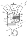
図1は、凝縮器として形成された中央に配置された熱伝達媒体8と、第1の流れダクト3並びに第2の流れダクト4を備えるハウジング2とを有する空調システム1を示しており、この場合、各々の流れダクト3、4にブロワ5、6が付設され、周囲からの新気、乗員室9からの循環内気又はそれらの両方からなる混合気がブロワに加えられる。
FIG. 1 shows an
この場合、中央の配置とは、2つの等しい大きさの領域に熱伝達媒体8を分割する隔壁10に対する熱伝達媒体8の配向と理解すべきである。第2の領域は、第2の流れダクト4の内部に配置されて、流れダクト4の流れ断面の全体を覆う。熱伝達媒体8の第1の領域は、第1の流れダクト3の内部に配置されて、流れダクト3の部分断面のみを覆う。
In this case, the central arrangement should be understood as the orientation of the
第2の流れダクト4には、凝縮器8のみが配置されるが、第1の流れダクト3には、さらに、蒸発器として形成された熱伝達媒体7が配置され、この場合、それらの両方は、空調システム1の冷媒回路の構成要素として、且つ空気が加えられる熱伝達媒体7、8として形成される。この場合、蒸発器7は、流れダクト3の流れ断面全体を占める。凝縮器8は、流れダクトに重なって配置され、2つの領域を備える。第2の領域は、第2の流れダクト4の内部に、流れ断面全体を覆うように配置され、当該領域の延長部は第1の流れダクト3内に達し、この結果、凝縮器8の第1の領域は第1の流れダクト3の内部に配置される。第1及び第2の流れダクト3、4は、隔壁10によって、並びに可動フラップとして形成された2つの追加の空気案内装置19、20によって、及び空気案内プレートとして形成された静的な空気案内装置21、22によって互いに分離される。凝縮器8を通して導かれる空気質量流は、ブロワ6の回転数及び空気案内装置19、20の位置に応じて決定される。
Only the
流れダクトに重なる凝縮器8の配置により、2つの領域への熱伝達面の調節可能な分割が行われる。この場合、凝縮器8は、熱伝達面全体の0%〜100%の範囲に分割可能である。0%もしくは100%の分割では、凝縮器8は、流れダクト3、4に完全に配置される。0%又は100%とは異なる熱伝達面の分割による熱伝達媒体装置の場合、領域は、部分的に流れダクト3の内部に及び流れダクト4の内部に配置され、例えば、熱伝達面の30%の分割による熱伝達媒体装置の場合、平面の30%が流れダクト3の内部に、70%が流れダクト4の内部に配置される。
The arrangement of the
本発明の変形実施形態(図示せず)によれば、流れダクトに重なる凝縮器8の配置により、同様に2つの領域への熱伝達面の調節不可能な分割が行われる。この場合、凝縮器8は、再び、熱伝達面全体の0%〜100%、しかし好ましくは0%〜30%の範囲に分割される。
According to a variant embodiment (not shown) of the invention, the arrangement of the
別々に調節可能なブロワ5、6は、空調システム1の有利な動的特性をもたらすが、この理由は、蒸発器7を有する第1の流れダクト3及び凝縮器8を有する第2の流れダクト4に、異なる速度の空気質量が加えられ、これによって、運転状態の変更に対する迅速な反応を可能にするからである。
The separately
第1の流れダクト3のブロワ5は、吸入された空気を空気質量流として蒸発器7に案内する。蒸発器7の熱伝達面を溢流する際、空気質量流は冷却され及び/又は除湿される。
The
蒸発器7から流出する冷却され及び/又は除湿された部分空気質量流は、冷気流れ経路11を介して周囲にまた冷気流れ経路12を介して乗員室9に、必要な比率で分割可能であるか、あるいは冷気流れ経路11、12の一方に完全に割り当てることができる。部分空気質量流は、フラップとして形成された空気案内装置13によって分割される。
The cooled and / or dehumidified partial air mass flow exiting the
冷気流れ経路12を通る部分空気質量流は、再び冷気質量流と後加熱のための部分空気質量流とに分割可能である。冷気流れ経路12を通して案内される冷気質量流は、バイパスダクト14を通して凝縮器8の周りに導かれる。後加熱のための部分空気質量流は、凝縮器8の第1の部分を介して導かれ、環境調節によって予め設定された温度に加熱される。
The partial air mass flow through the cold
ブロワ5と同様に、ブロワ6は空気を吸入し、吸入された空気を空気質量流として凝縮器8に案内する。凝縮器8の熱伝達面を溢流する際、空気質量流が加温される。
Similar to the
凝縮器8から流出する温風質量流は、温風流れ経路15を介した周囲への部分空気質量流として、また温風流れ経路16を介して乗員室9に必要な比率で部分空気質量流に分割可能であるか、あるいは温風流れ経路15、16の一方に完全に割り当てることができる。温風質量流は、フラップとして形成された空気案内装置17によって分割される。
The hot air mass flow flowing out of the
変形例として、フラップとして形成された空気案内装置13、17をそれぞれ2つの別個のフラップとして形成することができ、この場合、それぞれ2つのフラップが冷気流れ経路11、12の内部に、2つのフラップが温風流れ経路15、16の内部に配置される。この場合、それぞれ2つのフラップは、それぞれ1つの運動学的な装置によって連結され、唯一の駆動装置によって調整可能である。
As a variant, the
互いに調整された形状を備える空気案内装置19、20並びに空気案内プレート21、22は、熱伝達媒体用の空気案内装置を形成し、蒸発器7を貫流する際に冷却され且つ調和された流れダクト3の内部の空気質量流と、調和されていない第2の流れダクト4の空気質量流との混合の阻止に使用される。
The
空気案内プレートとして形成された空気案内装置21、22は、隔壁10に対して平行に整列されて配置され、この結果、隔壁10に沿って流れる空気質量流は、空気案内プレート21、22に当たって流れる際に、また側を流れもしくは貫流する際に流れ方向の方向転換を経験しない。
The
両側でそれぞれ流れダクト3、4内に、従って隔壁10からさらに遠くに配置された空気案内プレート21、22は、増大する長さLを有する。空気案内プレート21、22が隔壁10からさらに遠く配置されると、空気案内プレート21、22の長さLはそれだけ大きくなり、この場合、互いに並んで配置された空気案内プレート21、22の長さLは、空気案内プレート21、22の配置全体の端部が2つの凹状に形成された面23、24を形成するように増大する。面23、24は、それぞれ長方形に形成され、またそれぞれ面23、24に対して平行に整列される軸25、26の周りに均一に曲げられ、この結果、長方形の面23、24の第1の2つの対向する側縁部は、それぞれ1つの直線を形成し、一方、第2の2つの対向する側縁部は円弧を描く。
円弧の中心点は、それぞれ軸25、26を示し、これらの軸の周りに長方形の面23、24が曲げられる。この場合、軸25、26は、可動の空気案内装置19、20の回転軸25、26に対応する。円弧状に曲げられた面23、24の半径は、空気案内装置19、20の縦方向延長部に対応し、すなわち、流れダクト3、4を通る空気質量流の流れ方向の可動の空気案内装置19、20の延長部に対応する。
The
The center points of the arcs show
揺動可能な空気案内装置19、20は、回転軸25、26と反対側の側縁部により、凹状に湾曲した、空気案内プレート21、22の端部によって付勢された面23、24に対して整列される。空気案内装置19、20の自由な可動性のために、面23、24と空気案内装置19、20の側縁部との間に、空気質量流の流れに影響を及ぼさないかあるいは影響が無視できる程度である最小の幅の隙間が残る。
The swingable
反対の回転方向27、28のそれぞれの回転軸25、26を中心とする空気案内装置19、20の同時の回転によって、第1の流れダクト3並びに第2の流れダクト4の凝縮器8の領域の割合が調整可能である。この場合、凝縮器8の領域の分割は、ほぼ無段階に行うことができる。空気案内装置19、20の回転の内部の可能な段階は、流れダクト3、4を通る空気質量流の流れ方向に対して垂直の空気案内プレート21、22の間隔から得られる。空気案内装置19、20は、回転に従って、回転軸25、26に対して平行に且つ回転軸25、26から離れて配置された側縁部が、空気案内プレート21、22の端部に対向し、これによって、空気質量流が貫通する流れ面に沿って流れることができるように整列される。空気案内プレート21、22に関して空気案内装置19、20の中間位置に発生する漏流は、無視できる。中間位置とは、空気案内装置19、20の側縁部が空気案内プレート21、22の縁部に正確に対向せず、2つの空気案内プレート21、22の間に配置される空気案内装置19、20の位置と理解すべきである。
The region of the
空気案内プレート21、22の最大の縦方向延長部までの、すなわち第2の流れダクト4の外側ハウジング壁部に到達するまでの回転方向27、28の空気案内装置19、20の回転の際、全体の凝縮器8は、第1の流れダクト3の内部に配置される。空気案内装置19、20は第1の端部位置にある。空気案内プレート21、22の最大の縦方向延長部までの回転方向27、28と反対に置かれた空気案内装置19、20の回転の際、すなわち第1の流れダクト3の外側ハウジング壁部の方向もしくはバイパスダクト14の方向の回転の際に、全体の凝縮器8は、第2の流れダクト4の内部に配置される。空気案内装置19、20は第2の端部位置にある。両方の端部位置とならんで、空気案内装置19、20は中間位置で調整可能である。中央の中間位置が図1に示されている。
During the rotation of the
冷凍システムモード又はヒートポンプモードの運転時に、空気案内装置19、20は第2の端部位置に配置される。凝縮器8は、熱伝達面と共に完全に第2の流れダクト4の内部に配置される。
When operating in the refrigeration system mode or the heat pump mode, the
冷凍システムモードの運転時に、空気案内装置13はバイパスダクト14を開放し、周囲への冷気流れ経路11を閉鎖し、この結果、ブロワ5を通して吸入され、第1の流れダクト3を通して蒸発器7に搬送され、並びに蒸発器7を溢流する際に冷却され且つ除湿された空気質量流は、バイパスダクト14と冷気流れ経路12とを通して乗員室9に導かれる。他方で、第2の流れダクト4のブロワ6によって凝縮器8に搬送され、且つ凝縮器8を溢流する際に加温された空気質量流は、空気案内装置17によって開放される温風流れ経路15を通して周囲に運ばれる。温風流れ経路16は閉鎖される。空気案内装置19、20は、凝縮器8が完全に第2の流れダクト4に配置されるように整列される。
During operation in the refrigeration system mode, the
ヒートポンプモードの運転時に、すなわち乗員室9に供給されるべき空気の加温の際に、空気案内装置13は冷気流れ経路11を開放し、バイパスダクト14を閉鎖し、この結果、ブロワ5を通して吸入され、第1の流れダクト3を通して蒸発器7に搬送され、並びに蒸発器7を溢流する際に冷却された空気質量流は、冷気流れ経路11を通して周囲に運ばれる。他方で、ブロワ6によって吸入され且つ第2の流れダクト4を通して凝縮器8に搬送され、また凝縮器8を溢流する際に加温された空気質量流は、今や空気案内装置17によって開放される温風流れ経路16を通して乗員室9に導かれる。一方、温風流れ経路15は閉鎖される。
空気案内装置19、20は、凝縮器8が完全に第2の流れダクト4に配置されるように整列される。
During operation in the heat pump mode, that is, when the air to be supplied to the
The
この場合、ブロワ5、6は、流れダクト3、4を通る空気質量流の流れ方向に、それぞれ蒸発器7及び凝縮器8の前に配置される。ブロワ5、6の損失熱を空気に伝達することによって、空気質量流は、それぞれ約1K〜5Kだけ加温され、加温された状態で蒸発器7並びに凝縮器8に導かれる。これにより、ブロワ5、6の損失熱は、乗員室に供給されるべき空気を加温するために利用可能である。
In this case, the
後加熱モードの運転時に、空気案内装置13、17は、必要に応じて完全開と完全閉との間の様々な位置に配置され、空気案内装置19、20はそれらの位置の端部位置の間に配置される。空気案内装置13の位置並びにブロワ5の回転数によって、予め調和された加温されるべき空気質量流が変更される。
During operation in the after-heating mode, the
蒸発器7として形成された熱伝達媒体は、運転モードとは無関係に、すなわち冷凍システムモード及びヒートポンプモードの両方の運転時に、常に一方で、熱吸収のために冷媒が利用され、この場合、他方で、空気質量流が冷却され及び/又は除湿される。
The heat transfer medium formed as an
凝縮器8として形成された熱伝達媒体が、同様に運転モードとは無関係に、冷媒から空気質量流に熱放出するために常に使用される。
A heat transfer medium formed as a
図2a〜図2eによる実施形態は、図1による空調システム1と比較して、第1の流れダクト3を通る空気質量流及び第2の流れダクト4を通る空気質量流の両方を搬送する1つのみのブロワ29を備える。この空調システム1は、空気案内装置13、19、20として形成された制御のために十分であるほぼ3つの空気案内要素を含む。この場合、空気案内装置20は、図1の空気案内装置17の機能、すなわち温風流れ経路15、16の開閉を引き受ける。第4のフラップとして形成された空気案内装置18は、バイパスダクト14の開閉に使用される。さらに、空気案内装置18により、蒸発器7もしくは凝縮器8を介して空気質量流の比率を調整することができる。
The embodiment according to FIGS. 2 a-2 e carries both an air mass flow through the
図2bによる冷凍システムモードの運転時に、空気案内装置19、20は第2の端部位置に配置され、この結果、凝縮器8は完全に第2の流れダクト4の内部に配置される。空気案内装置13は、冷気流れ経路12を開放し、周囲への冷気流れ経路11を閉鎖する。蒸発器7を溢流する際に冷却され且つ除湿された空気質量流は、冷気流れ経路12を通して乗員室9に導かれる。凝縮器8を溢流する際に加温された空気質量流は、空気案内装置20によって開放される温風流れ経路15を通して周囲に案内される。温風流れ経路16は閉鎖される。
During operation in the refrigeration system mode according to FIG. 2 b, the
図2dによる調和されていない空気を有するヒートポンプモードの運転時、空気案内装置13は冷気流れ経路11を開放し、乗員室9への冷気流れ経路12を閉鎖し、この結果、蒸発器7を溢流する際に冷却された空気質量流は、冷気流れ経路11を通して周囲に運ばれる。他方で、凝縮器8を溢流する際に加温された空気質量流は、今や空気案内装置20によって開放される温風流れ経路16を通して乗員室9に搬送され、一方、温風流れ経路15は閉鎖される。
During operation in the heat pump mode with unconditioned air according to FIG. 2 d, the
空気案内装置19、20は、互いに反対方向に配置される。空気案内装置19は第1の端部位置にあり、一方、空気案内装置20は第2の端部位置に配置され、同時に温風流れ経路15を閉鎖し、並びに温風流れ経路16を開放する。
The
純粋なヒートポンプモードの運転又は調和されていない空気による加熱運転は、乗員室9に供給されるべき空気の除湿が必要でないか又は所望でない場合に切り替えられる。ブロワ29は、吸入される空気の流れ方向に蒸発器7及び凝縮器8の前に配置され、この結果、ブロワ29の損失熱を空気に熱伝達することによって、空気質量流は約1K〜5Kだけ加温され、加温された状態で蒸発器7並びに凝縮器8に導かれる。これにより、ブロワ29の損失熱は、乗員室に供給されるべき空気を加温するために利用可能である。
Operation in pure heat pump mode or heating operation with unconditioned air is switched when dehumidification of the air to be supplied to the
フルの加熱運転による加温及び乗員室9に供給されるべき空気の同時の除湿が必要な場合、第2の流れダクト4が空気案内装置19によって閉鎖され、この場合、空気案内装置19は、空気案内装置20と同様に第2の端部位置にあり、このことは図2cから読み取られる。ブロワ29によって搬送される空気質量流全体は、蒸発器7を介して案内される。空気案内装置18がバイパスダクト14を閉鎖するであろう。
When heating by full heating operation and simultaneous dehumidification of the air to be supplied to the
凝縮器8において放出されるべき熱出力は、蒸発器7、圧縮機及び凝縮器8を含む閉鎖した冷媒回路では、蒸発器7及び圧縮機の冷媒に供給される出力の和から得られ、従って、凝縮器8における熱出力は、圧縮機で供給される出力だけ蒸発器7に供給される出力よりも大きいので、空気は、凝縮器8の熱伝達面を溢流する際に僅かにのみ加温することができる。従って、同一の空気質量流では、単に圧縮機出力並びに空気の純粋な除湿による出力を再び供給することができ、この場合、システムの損失もなお考慮すべきである。
The heat output to be released in the
凝縮器8におけるより大きな熱出力を達成するために、また乗員室9に供給されるべき空気質量流をより強く加温するために、蒸発器7を介して流され並びにこの際に冷却され且つ除湿される空気質量流の第1の部分が周囲に導出され、一方、空気質量流の第2の部分は凝縮器8を介して案内され、この際に加温され、次に乗員室9に搬送される。空気質量流は、バイパスダクト14に配置された空気案内装置18の制御部によって分割される。
In order to achieve a greater heat output in the
乗員室9に搬送される空気質量流は、周囲に排出された部分だけ低減されるので、乗員室9に搬送される空気質量流のより強い加温が可能である。
Since the air mass flow conveyed to the
図2eが示すように、空調システム1は、冷凍システムモード及び純粋な加熱モードにおける運転に加えて、混合モードにおいても運転可能である。この場合、調和された空気は、冷却され且つ除湿された空気の部分から、並びに冷却され、除湿され且つ再加温された空気の部分から構成される。
As shown in FIG. 2e, the
ブロワ29は、第1の流れダクト3を通して、蒸発器7を介して完全に流れ、この際に冷却且つ除湿される空気質量流を搬送し、並びに第2の流れダクト4を通して、凝縮器8の部分領域を介して案内され、且つ蒸発器7に吸収された熱を再び誘導する空気質量流を搬送する。この場合、空気案内装置19、20は、凝縮器8の第2の領域が第2の流れダクト4に、及び凝縮器8の第1の領域が第1の流れダクト3に配置されるように整列される。第2の流れダクト4を通して搬送される空気質量流は、空気案内装置20によって開放される温風流れ経路15を通して周囲に導出される。
The
蒸発器7を介して流れる際に調和された空気質量流の第1の部分は、空気案内装置18を開放することによってバイパスダクト14を通して冷気流れ経路12に導かれる。空気質量流のこの部分はさらに調和されない。蒸発器7を介して案内された部分空気質量流の第2の部分は、流れダクト4の部分空気質量流に対して平行に凝縮器8の第1の領域を介して温風流れ経路16に案内され、この際に加温される。バイパスダクト14を通して導かれ、さらに調和されない、すなわち冷却及び除湿のみが行われる冷気流れ経路12からの部分空気質量流は、さらに凝縮器8を介して導かれ、この際に加温される温風流れ経路16からの部分空気質量流と混合され、次に乗員室9に導入される。
A first portion of the conditioned air mass flow as it flows through the
1 空調システム
2 ハウジング
3 第1の流れダクト
4 第2の流れダクト
5、6 ブロワ
7 熱伝達媒体、蒸発器
8 熱伝達媒体、凝縮器
9 乗員室
10 隔壁
11、12 冷気流れ経路
13 冷気流れ経路の空気案内装置/フラップ
14 第1の流れダクトのバイパスダクト
15、16 温風流れ経路
17 温風流れ経路の空気案内装置/フラップ
18 バイパスダクト用の空気案内装置/フラップ
19 凝縮器に当たって流れるための第1の流れダクトと第2の流れダクトとの間の空気案内装置/フラップ
20 凝縮器に当たって流れる際の第1の流れダクトと第2の流れダクトとの間の空気案内装置/フラップ
21、22 静的な空気案内装置/空気案内プレート
23、24 静的な空気案内装置の面
25、26 空気案内装置の軸、回転軸
27、28 空気案内装置の回転方向
29 ブロワ
L 長さ
DESCRIPTION OF
Claims (8)
ブロワ(5)と、空気案内部と、蒸発器(7)と、を有し、前記蒸発器(7)が、冷媒回路に一体化され、前記冷媒によって貫流可能であり、熱を空気から冷媒に伝達可能であるように形成され、前記冷媒が蒸発され、
前記ブロワ(5)は、空気が前記蒸発器(7)に達する前に損失熱が空気を加温するように、空気の流れ方向において前記蒸発器(7)の上流に配置され、
前記蒸発器(7)は、一列に配置された管を備えた管熱交換器として形成され、前記管熱交換器が少なくとも2列に形成され、
前記空調システム(1)は、さらに、空気を導くための第1の流れダクト(3)及び第2の流れダクト(4)を備えると共に、前記第1の流れダクト(3)と前記第2の流れダクト(4)との間に位置決めされた隔壁(10)を備えたハウジング(2)を有し、
前記冷媒回路は、圧縮機と、凝縮器(8)と、膨張器と、を備え、前記蒸発器(7)は、前記第1の流れダクト(3)内のみに配置され、前記凝縮器(8)は、前記第2の流れダクト(4)に配置され、
前記空調システム(1)は、前記乗員室(9)の冷却用の冷凍運転及び加熱用のヒートポンプ運転、並びに、後加熱運転用に設計され、前記蒸発器(7)は、運転モードに関わらず機能し、
前記凝縮器(8)は、熱伝達面を備え、この熱伝達面は、前記第1の流れダクト(3)の断面に部分的に配置される第1の領域と、前記第2の流れダクト(4)の断面全体に配置される第2の領域と、を備え、
前記凝縮器(8)は、前記隔壁(10)と平行に配置されて前記凝縮器の前側に配列された複数の空気案内プレート(21)を備え、これら複数の空気案内プレート(21)の配列の端部は、空気案内装置(19)によって調節可能に仕切られている表面(23)を形成し、前記凝縮器(8)の熱伝達面は、0%〜100%の割合で調節可能に分割可能であることを特徴とする空調システム(1)。 An air conditioning system (1) for conditioning air in a passenger compartment (9) of an automobile having a heat exchanger device for cooling air,
A blower (5), an air guide, and an evaporator (7). The evaporator (7) is integrated in a refrigerant circuit and can flow through the refrigerant; The refrigerant is evaporated,
The blower (5) is arranged upstream of the evaporator (7) in the air flow direction so that the heat of loss heats the air before it reaches the evaporator (7),
The evaporator (7) is formed as a tube heat exchanger with tubes arranged in a row, the tube heat exchanger is formed in at least two rows,
The air conditioning system (1) further includes a first flow duct for directing air (3) and a second Rutotomoni includes a flow duct (4), said first flow duct (3) and the second A housing (2) with a partition wall (10) positioned between the flow duct (4) of
The refrigerant circuit includes a compressor, a condenser (8), and an expander. The evaporator (7) is disposed only in the first flow duct (3) , and the condenser ( 8) is arranged in the second flow duct (4),
The air conditioning system (1) is designed for refrigeration operation for cooling the passenger compartment (9), heat pump operation for heating, and post-heating operation, and the evaporator (7) is independent of the operation mode. Function,
The condenser (8) comprises a heat transfer surface, the heat transfer surface being partly arranged in a cross section of the first flow duct (3) and the second flow duct. A second region disposed over the entire cross section of (4) ,
The condenser (8) includes a plurality of air guide plates (21) arranged in parallel to the partition wall (10) and arranged on the front side of the condenser, and the arrangement of the plurality of air guide plates (21). The end portion of the air-conditioner forms a surface (23) that can be adjusted by an air guide device (19), and the heat transfer surface of the condenser (8) can be adjusted at a rate of 0% to 100%. An air conditioning system (1) characterized in that it can be divided.
前記後加熱運転は、
前記空調システム(1)で第1の部分空気質量流及び第2の部分空気質量流を搬送する段階と、
前記蒸発器(7)を通過する際に前記第1の部分空気質量流を冷却する段階と、
前記冷却された第1の部分空気質量流を、周囲に導出される部分空気質量流と、後加熱のための部分空気質量流と、冷凍空気質量流とに分割する段階と、
前記凝縮器(8)の熱伝達面を通過する際に、前記第2の部分空気質量流と、後加熱のための前記部分空気質量流とを加温する段階と、
前記後加熱された部分空気質量流と予め調和された冷凍空気質量流とを混合する段階であって、
利用される冷却能力が、前記蒸発器(7)の後の前記第1の部分空気質量流の温度と前記蒸発器(7)内の冷媒の圧力レベルとによって調節され、
前記混合された空気質量流の温度が、前記空気質量流に配置された少なくとも1つの温度センサによって検出され、且つ空気案内装置(13、18、19、20)の位置を通る後加熱のための前記部分空気質量流と、前記予め調和された冷凍空気質量流との比率によって調節される混合する段階と、
前記混合された空気質量流を前記乗員室(9)内に導く段階と、
を有することを特徴とする方法。 For a combination of a refrigeration system operation for cooling air in the passenger compartment (9) of the automobile and a heat pump operation for heating air in the passenger compartment (9) of the automobile, and the passenger compartment (9) of the automobile A method of operating an air conditioning system (1) according to any one of claims 1 to 5 for post-heating operation to harmonize the air of
The post-heating operation is
Conveying a first partial air mass flow and a second partial air mass flow in the air conditioning system (1);
Cooling the first partial air mass flow as it passes through the evaporator (7);
Splitting the cooled first partial air mass flow into a partial air mass flow derived to the surroundings, a partial air mass flow for post-heating, and a refrigeration air mass flow;
Heating the second partial air mass flow and the partial air mass flow for post-heating as it passes through the heat transfer surface of the condenser (8);
Mixing the post-heated partial air mass flow with a pre-conditioned refrigerated air mass flow comprising:
The cooling capacity utilized is adjusted by the temperature of the first partial air mass flow after the evaporator (7) and the pressure level of the refrigerant in the evaporator (7),
The temperature of the mixed air mass flow is detected by at least one temperature sensor arranged in the air mass flow and for post-heating through the position of the air guiding device (13, 18, 19, 20) Mixing adjusted by the ratio of the partial air mass flow and the pre-conditioned refrigerated air mass flow;
Directing the mixed air mass flow into the passenger compartment (9);
A method characterized by comprising:
Applications Claiming Priority (4)
| Application Number | Priority Date | Filing Date | Title |
|---|---|---|---|
| DE102012108889 | 2012-09-20 | ||
| DE102012108889.6 | 2012-09-20 | ||
| DE102013106209.1A DE102013106209B4 (en) | 2012-09-20 | 2013-06-14 | Air conditioning device of a motor vehicle with a heat exchanger arrangement for absorbing heat |
| DE102013106209.1 | 2013-06-14 |
Publications (3)
| Publication Number | Publication Date |
|---|---|
| JP2014061878A JP2014061878A (en) | 2014-04-10 |
| JP2014061878A5 JP2014061878A5 (en) | 2015-04-30 |
| JP5951571B2 true JP5951571B2 (en) | 2016-07-13 |
Family
ID=50181862
Family Applications (1)
| Application Number | Title | Priority Date | Filing Date |
|---|---|---|---|
| JP2013195621A Active JP5951571B2 (en) | 2012-09-20 | 2013-09-20 | Heat transfer medium device and air conditioning system for heat absorption of automobile |
Country Status (4)
| Country | Link |
|---|---|
| US (1) | US9821625B2 (en) |
| JP (1) | JP5951571B2 (en) |
| CN (1) | CN103673257B (en) |
| DE (1) | DE102013106209B4 (en) |
Families Citing this family (24)
| Publication number | Priority date | Publication date | Assignee | Title |
|---|---|---|---|---|
| DE102013219811A1 (en) * | 2013-09-30 | 2015-04-02 | Behr Gmbh & Co. Kg | air conditioning |
| DE102014104969B4 (en) * | 2014-04-08 | 2019-11-21 | Hanon Systems | Air conditioning system for a motor vehicle |
| FR3026351B1 (en) * | 2014-09-25 | 2018-03-23 | Valeo Systemes Thermiques | DEVICE FOR GENERATING AN AIR FLOW |
| FR3027124B1 (en) * | 2014-10-14 | 2016-11-25 | Airbus Helicopters | METHOD OF CONTROLLING UNDER GIVING CONDITIONS OF THE TRAINING SPEED OF A ROTOR OF GIRAVION |
| DE102015117962A1 (en) * | 2014-10-24 | 2016-04-28 | Hanon Systems | Air conditioning system for conditioning the air of a passenger compartment of a motor vehicle |
| KR101628530B1 (en) * | 2014-11-17 | 2016-06-09 | 현대자동차주식회사 | Air conditioner for vehicle |
| KR101628558B1 (en) * | 2014-12-05 | 2016-06-09 | 현대자동차주식회사 | Air conditioner of vehicle |
| JP2018500531A (en) * | 2014-12-10 | 2018-01-11 | コーウェイ カンパニー リミテッドCoway Co., Ltd. | Dehumidifying / humidifying device, dehumidifying air purifier, humidified air purifier, and operation method thereof |
| US20170368914A1 (en) * | 2015-01-09 | 2017-12-28 | Carrier Corporation | Removable external bulkhead for transportation refrigeration unit |
| WO2016163771A1 (en) * | 2015-04-08 | 2016-10-13 | 한온시스템 주식회사 | Vehicle air-conditioning system |
| US20180093545A1 (en) * | 2015-04-08 | 2018-04-05 | Hanon Systems | Air conditioning system for vehicle |
| FR3035192B1 (en) * | 2015-04-15 | 2018-11-09 | Valeo Systemes Thermiques | DEVICE FOR GENERATING AN AIR FLOW AND HEATING, VENTILATION AND / OR AIR CONDITIONING INSTALLATION |
| KR101822287B1 (en) * | 2016-07-04 | 2018-01-26 | 현대자동차주식회사 | Air conditioning system for vehicle |
| KR101822288B1 (en) * | 2016-07-06 | 2018-01-26 | 현대자동차주식회사 | Air conditioning apparatus for vehicle |
| KR102334606B1 (en) * | 2017-04-14 | 2021-12-06 | 한온시스템 주식회사 | Method for controlling air conditioning system for automotive vehicles |
| US20180345751A1 (en) * | 2017-06-05 | 2018-12-06 | Denso International America, Inc. | Hvac system |
| JP6870570B2 (en) * | 2017-10-26 | 2021-05-12 | 株式会社デンソー | Vehicle heat management system |
| DE102018124748B4 (en) * | 2017-11-24 | 2023-02-09 | Hanon Systems | Multi-zone air conditioning for vehicles |
| DE102018203540A1 (en) * | 2018-03-08 | 2019-09-12 | Volkswagen Aktiengesellschaft | Air conditioning device of a motor vehicle with a heat pump and method for operating such a heat pump |
| US10974570B2 (en) | 2018-04-19 | 2021-04-13 | Toyota Motor Engineering & Manufacturing North America, Inc. | Limit for compressor speed based on inverter temperature for air conditioner in vehicle |
| JP2020019352A (en) * | 2018-07-31 | 2020-02-06 | サンデンホールディングス株式会社 | Vehicular air conditioner |
| CN110789290B (en) * | 2018-08-01 | 2023-04-07 | 上海汽车集团股份有限公司 | Air conditioning box of vehicle heat pump system and ventilation strategy thereof |
| FR3086744B1 (en) * | 2018-09-27 | 2020-12-04 | Valeo Systemes Thermiques | AUTOMOTIVE VEHICLE THERMAL EXCHANGE MODULE |
| KR102661622B1 (en) * | 2018-11-12 | 2024-04-29 | 현대자동차주식회사 | Air conditioning unit for vehicle |
Family Cites Families (31)
| Publication number | Priority date | Publication date | Assignee | Title |
|---|---|---|---|---|
| DE3513952A1 (en) * | 1985-04-18 | 1986-10-23 | Thermal-Werke Wärme-Kälte-Klimatechnik GmbH, 6832 Hockenheim | Heating, ventilating and air-conditioning system for tour buses |
| JP3306880B2 (en) * | 1991-08-28 | 2002-07-24 | 株式会社デンソー | Vehicle air conditioner |
| JP2962019B2 (en) | 1991-12-27 | 1999-10-12 | 株式会社デンソー | Vehicle air conditioner |
| JP3085329B2 (en) * | 1992-07-14 | 2000-09-04 | 株式会社デンソー | Vehicle air conditioner |
| JPH0640242A (en) * | 1992-07-22 | 1994-02-15 | Nissan Motor Co Ltd | Auxiliary hydraulic driving device for automobile |
| JP2568272Y2 (en) * | 1993-03-25 | 1998-04-08 | 株式会社ゼクセル | Automotive air conditioning controller |
| JP3456021B2 (en) * | 1994-07-29 | 2003-10-14 | 株式会社デンソー | Vehicle air conditioner |
| JP3325421B2 (en) * | 1995-03-07 | 2002-09-17 | カルソニックカンセイ株式会社 | Cooling and heating system for electric vehicles |
| FR2743027B1 (en) * | 1995-12-29 | 1998-01-23 | Renault | AIR CONDITIONING DEVICE FOR THE VEHICLE INTERIOR |
| JPH10329535A (en) * | 1997-05-28 | 1998-12-15 | Calsonic Corp | Air conditioner for automobile |
| DE19745028A1 (en) * | 1997-10-11 | 1999-04-15 | Behr Gmbh & Co | Procedure for evaporator icing-protected control for air conditioning plant |
| FR2774035B1 (en) * | 1998-01-29 | 2000-03-31 | Valeo Climatisation | MOTOR VEHICLE HEATING AND / OR AIR CONDITIONING DEVICE WITH IMPROVED HEAT EXCHANGE MANAGEMENT |
| US6715307B2 (en) * | 2001-01-24 | 2004-04-06 | Calsonic Kansei Corporation | Air conditioner for vehicle |
| JP4682489B2 (en) | 2001-09-17 | 2011-05-11 | 株式会社デンソー | Air conditioner for vehicles |
| MXPA04006151A (en) * | 2001-12-21 | 2004-11-01 | Behr Gmbh & Co Kg | Device for exchanging heat. |
| JP3911229B2 (en) * | 2002-10-24 | 2007-05-09 | サンデン株式会社 | Air conditioner for vehicles |
| JP4134687B2 (en) | 2002-11-08 | 2008-08-20 | 株式会社デンソー | Air conditioner for vehicles |
| JP4124136B2 (en) * | 2003-04-21 | 2008-07-23 | 株式会社デンソー | Refrigerant evaporator |
| DE10337753A1 (en) | 2003-08-08 | 2005-03-03 | Robert Bosch Gmbh | Air conditioning, in particular for use in motor vehicles and methods for their operation |
| JP4075831B2 (en) | 2004-03-24 | 2008-04-16 | 株式会社デンソー | Air conditioner for vehicles |
| US7578734B2 (en) * | 2006-06-19 | 2009-08-25 | Trane International Inc. | Unit ventilator having a splitter plate and a pivoting damper blade assembly |
| DE102007046663A1 (en) * | 2006-09-29 | 2008-05-21 | Behr America, Inc., Troy | Auxiliary climate control system for vehicle e.g. commercial truck, has blower and heat exchanger assembly having Z-shaped configuration |
| CN101936670B (en) * | 2009-06-30 | 2013-05-15 | 王磊 | Heat exchanger with micro-channel, parallel-flow and all-aluminum flat pipe welding structure and application |
| JP5446524B2 (en) | 2009-07-08 | 2014-03-19 | 株式会社デンソー | Air conditioner for vehicles |
| DE102009028522B4 (en) * | 2009-08-13 | 2017-05-11 | Hanon Systems | Compact air conditioning system for a motor vehicle |
| DE102009052409B4 (en) * | 2009-11-10 | 2018-03-15 | Stiebel Eltron Gmbh & Co. Kg | heat pump system |
| WO2012114767A1 (en) * | 2011-02-24 | 2012-08-30 | パナソニック株式会社 | Air conditioning device for vehicle |
| DE102011051285B4 (en) * | 2011-06-23 | 2015-11-12 | Halla Visteon Climate Control Corporation | Method and device for anti-icing control for evaporators of a heat pump of air conditioning systems in vehicles |
| DE102011052285B4 (en) | 2011-07-29 | 2021-09-02 | Leopold Möschl | Wall plugs |
| DE102011052752A1 (en) * | 2011-08-16 | 2013-02-21 | Visteon Global Technologies, Inc. | Modular vehicle air conditioning with heat pump functionality |
| DE102012108891B4 (en) * | 2012-09-20 | 2022-01-27 | Hanon Systems | Air-conditioning system for a motor vehicle and air-guiding device for a heat exchanger |
-
2013
- 2013-06-14 DE DE102013106209.1A patent/DE102013106209B4/en active Active
- 2013-09-20 JP JP2013195621A patent/JP5951571B2/en active Active
- 2013-09-20 US US14/032,918 patent/US9821625B2/en active Active
- 2013-09-22 CN CN201310432328.6A patent/CN103673257B/en active Active
Also Published As
| Publication number | Publication date |
|---|---|
| DE102013106209A1 (en) | 2014-03-20 |
| US9821625B2 (en) | 2017-11-21 |
| US20140075975A1 (en) | 2014-03-20 |
| JP2014061878A (en) | 2014-04-10 |
| DE102013106209B4 (en) | 2020-09-10 |
| CN103673257A (en) | 2014-03-26 |
| CN103673257B (en) | 2018-05-29 |
Similar Documents
| Publication | Publication Date | Title |
|---|---|---|
| JP5951571B2 (en) | Heat transfer medium device and air conditioning system for heat absorption of automobile | |
| JP6231337B2 (en) | Automotive heat exchanger apparatus and air conditioning system | |
| JP6125565B2 (en) | Automotive air conditioning system | |
| JP5967403B2 (en) | Air conditioner for vehicles | |
| US10160290B2 (en) | Modular designed high performance heat pump system for a vehicle with low waste heat radiation | |
| US10953727B2 (en) | Air-conditioning system of a motor vehicle and method for operating the air-conditioning system | |
| CN104972865B (en) | Air conditioning system for automobile | |
| JP7243410B2 (en) | Vehicle battery heating device | |
| KR20190103005A (en) | Air-conditioning system of a motor vehicle and method for operating the air-conditioning system | |
| JP2011037434A (en) | Small temperature control system for vehicle | |
| WO2014156585A1 (en) | Air-conditioning device for vehicle | |
| US10363792B2 (en) | Air-conditioning system for cooling and drying air in passenger compartment of vehicle | |
| CN110520313B (en) | Vehicle air conditioning apparatus | |
| US20170217278A1 (en) | Air conditioning system for conditioning air in automobile passenger compartment | |
| KR20190068356A (en) | Air conditioning system for vehicle | |
| JP3563094B2 (en) | Vehicle air conditioner | |
| KR102111322B1 (en) | Heat pump system for vehicle | |
| JP2011121430A (en) | Air conditioner for vehicle | |
| US7805960B2 (en) | System for air-conditioning an environment, in particular the passenger compartment of a motor vehicle | |
| KR102158496B1 (en) | Heat pump system for vehicle | |
| JPH06206439A (en) | Heat pump type air-conditioning device for vehicle | |
| KR101755929B1 (en) | Air conditioning system for vehicle | |
| CN112092568B (en) | Temperature adjusting system and method and vehicle | |
| CN108072186B (en) | Air conditioning system | |
| JPH06206433A (en) | Heat pump type air-conditioning device for vehicle |
Legal Events
| Date | Code | Title | Description |
|---|---|---|---|
| A711 | Notification of change in applicant |
Free format text: JAPANESE INTERMEDIATE CODE: A711 Effective date: 20140508 |
|
| A131 | Notification of reasons for refusal |
Free format text: JAPANESE INTERMEDIATE CODE: A131 Effective date: 20141125 |
|
| A977 | Report on retrieval |
Free format text: JAPANESE INTERMEDIATE CODE: A971007 Effective date: 20141128 |
|
| A601 | Written request for extension of time |
Free format text: JAPANESE INTERMEDIATE CODE: A601 Effective date: 20150224 |
|
| A524 | Written submission of copy of amendment under article 19 pct |
Free format text: JAPANESE INTERMEDIATE CODE: A524 Effective date: 20150311 |
|
| A131 | Notification of reasons for refusal |
Free format text: JAPANESE INTERMEDIATE CODE: A131 Effective date: 20150831 |
|
| A521 | Request for written amendment filed |
Free format text: JAPANESE INTERMEDIATE CODE: A523 Effective date: 20151125 |
|
| TRDD | Decision of grant or rejection written | ||
| A01 | Written decision to grant a patent or to grant a registration (utility model) |
Free format text: JAPANESE INTERMEDIATE CODE: A01 Effective date: 20160509 |
|
| A61 | First payment of annual fees (during grant procedure) |
Free format text: JAPANESE INTERMEDIATE CODE: A61 Effective date: 20160608 |
|
| R150 | Certificate of patent or registration of utility model |
Ref document number: 5951571 Country of ref document: JP Free format text: JAPANESE INTERMEDIATE CODE: R150 |
|
| R250 | Receipt of annual fees |
Free format text: JAPANESE INTERMEDIATE CODE: R250 |
|
| R250 | Receipt of annual fees |
Free format text: JAPANESE INTERMEDIATE CODE: R250 |
|
| R250 | Receipt of annual fees |
Free format text: JAPANESE INTERMEDIATE CODE: R250 |
|
| R250 | Receipt of annual fees |
Free format text: JAPANESE INTERMEDIATE CODE: R250 |
|
| R250 | Receipt of annual fees |
Free format text: JAPANESE INTERMEDIATE CODE: R250 |