JP5950699B2 - COMMUNICATION DEVICE AND ITS CONTROL METHOD - Google Patents
COMMUNICATION DEVICE AND ITS CONTROL METHOD Download PDFInfo
- Publication number
- JP5950699B2 JP5950699B2 JP2012125145A JP2012125145A JP5950699B2 JP 5950699 B2 JP5950699 B2 JP 5950699B2 JP 2012125145 A JP2012125145 A JP 2012125145A JP 2012125145 A JP2012125145 A JP 2012125145A JP 5950699 B2 JP5950699 B2 JP 5950699B2
- Authority
- JP
- Japan
- Prior art keywords
- address
- wireless network
- network
- communication device
- setting
- Prior art date
- Legal status (The legal status is an assumption and is not a legal conclusion. Google has not performed a legal analysis and makes no representation as to the accuracy of the status listed.)
- Active
Links
Images


Classifications
-
- H—ELECTRICITY
- H04—ELECTRIC COMMUNICATION TECHNIQUE
- H04L—TRANSMISSION OF DIGITAL INFORMATION, e.g. TELEGRAPHIC COMMUNICATION
- H04L61/00—Network arrangements, protocols or services for addressing or naming
- H04L61/50—Address allocation
- H04L61/5007—Internet protocol [IP] addresses
-
- H—ELECTRICITY
- H04—ELECTRIC COMMUNICATION TECHNIQUE
- H04L—TRANSMISSION OF DIGITAL INFORMATION, e.g. TELEGRAPHIC COMMUNICATION
- H04L61/00—Network arrangements, protocols or services for addressing or naming
- H04L61/50—Address allocation
- H04L61/5046—Resolving address allocation conflicts; Testing of addresses
-
- H—ELECTRICITY
- H04—ELECTRIC COMMUNICATION TECHNIQUE
- H04L—TRANSMISSION OF DIGITAL INFORMATION, e.g. TELEGRAPHIC COMMUNICATION
- H04L61/00—Network arrangements, protocols or services for addressing or naming
- H04L61/50—Address allocation
- H04L61/5007—Internet protocol [IP] addresses
- H04L61/5014—Internet protocol [IP] addresses using dynamic host configuration protocol [DHCP] or bootstrap protocol [BOOTP]
-
- H—ELECTRICITY
- H04—ELECTRIC COMMUNICATION TECHNIQUE
- H04L—TRANSMISSION OF DIGITAL INFORMATION, e.g. TELEGRAPHIC COMMUNICATION
- H04L2101/00—Indexing scheme associated with group H04L61/00
- H04L2101/60—Types of network addresses
- H04L2101/618—Details of network addresses
- H04L2101/622—Layer-2 addresses, e.g. medium access control [MAC] addresses
Landscapes
- Engineering & Computer Science (AREA)
- Computer Networks & Wireless Communication (AREA)
- Signal Processing (AREA)
- Mobile Radio Communication Systems (AREA)
- Small-Scale Networks (AREA)
Description
複数の通信インターフェースを有する通信装置においてIPアドレスの自動割当に関するものである。 The present invention relates to automatic assignment of IP addresses in a communication apparatus having a plurality of communication interfaces.
近年、IEEE802.11に代表される無線LANシステムが広く利用されるようになっている。 In recent years, wireless LAN systems represented by IEEE 802.11 have come to be widely used.
無線LANには、インフラストラクチャモードとアドホックモードの2つのモードが存在する。インフラストラクチャモードでは無線ネットワークの管理を行うアクセスポイント(以下、AP)とその無線ネットワークに接続して通信を行う通信端末(以下、STA)でインフラストラクチャネットワークを構成する。インフラストラクチャネットワークにおけるSTAのデータ通信は常にAPを経由して行われる。 The wireless LAN has two modes, an infrastructure mode and an ad hoc mode. In the infrastructure mode, an infrastructure network is configured by an access point (hereinafter referred to as AP) that manages a wireless network and a communication terminal (hereinafter referred to as STA) that communicates by connecting to the wireless network. STA data communication in the infrastructure network is always performed via the AP.
また、インフラストラクチャネットワークではAPを介して広域通信網(以下、WAN)との通信が可能である。そのため、データ通信には、LAN内のDHCPサーバ又はAPが内蔵するDHCPサーバ機能により割り当てられたルータブルアドレスを用いるのが一般的である。 In addition, the infrastructure network can communicate with a wide area communication network (hereinafter referred to as WAN) via the AP. Therefore, for data communication, it is common to use a routable address assigned by a DHCP server function in the DHCP server or AP built in the LAN.
ここで、ルータブルアドレスとは、ルータに転送可能なIPアドレスを示している。また、NATを使用する場合、DHCPで割り当てるアドレスはプライベートアドレスを用いるのが一般的である。IPv4におけるプライベートアドレスの一例としては、192.168.0.0〜192.168.255.255が利用されている。 Here, the routable address indicates an IP address that can be transferred to the router. In addition, when NAT is used, a private address is generally used as an address assigned by DHCP. As an example of a private address in IPv4, 192.168.0.0 to 192.168.255.255 is used.
一方、アドホックモードは、無線ネットワークを管理する装置を必要とせず、STAのみでアドホックネットワークを構成する。アドホックネットワークにおけるデータ通信は各STA間で直接行われる。また、アドホックネットワークでは、ネットワークを管理する装置が存在しないという特性上、データ通信にはAutoIPによりリンクローカルアドレスを用いるか、手動でプライベートアドレスを用いるのが一般的である。 On the other hand, the ad hoc mode does not require a device for managing a wireless network, and forms an ad hoc network only with STAs. Data communication in the ad hoc network is performed directly between the STAs. Further, in an ad hoc network, because there is no device for managing the network, it is common to use a link local address by AutoIP or manually use a private address for data communication.
ここで、IPv4におけるリンクローカルアドレスとしては、169.254.0.0〜169.254.255.255が利用されている。 Here, 169.254.0.0 to 169.254.255.255 are used as link local addresses in IPv4.
近年では、インフラストラクチャモードとアドホックモードの両方の機能を同時動作可能な機器やAPとSTAの両方の機能を同時動作可能な機器が開発されている(特許文献1参照)。これらの機能を実現する構成として、それぞれの機能を実現する無線ハードウェアを個別に設けてもよいが、その分コストが上がるので大抵の機器は一つの無線ハードウェアを各機能で共通に使用している。 In recent years, devices capable of operating both infrastructure mode and ad hoc mode functions simultaneously and devices capable of operating both AP and STA functions simultaneously have been developed (see Patent Document 1). As a configuration that realizes these functions, wireless hardware that realizes each function may be provided separately, but since the cost increases accordingly, most devices commonly use one wireless hardware for each function. ing.
このような機器では、内部的にインフラストラクチャモードとアドホックモードまたはAPとSTAを夫々別の通信インターフェースとして管理するのが一般的である。そのため、物理的に複数のインターフェースを有する機器と同様の制御が必要となる。 In such devices, it is common to internally manage infrastructure mode and ad hoc mode or AP and STA as separate communication interfaces. Therefore, the same control as that of a device having a plurality of physical interfaces is required.
無線ハードウェアを複数の機能で共通に使用する場合、各機能で異なるMACアドレスを使用することも可能であるが、単一のMACアドレスを使用することも可能である。どちらの方法を採用するかは、通信IFの提供ベンダの実装に依存しており、その通信IFの提供を受けるセットメーカ等では選択できない場合がほとんどである。 When wireless hardware is used in common by a plurality of functions, it is possible to use different MAC addresses for each function, but it is also possible to use a single MAC address. Which method is adopted depends on the implementation of the vendor providing the communication IF, and in most cases, it cannot be selected by the set maker receiving the communication IF.
また、このような機器では、各機能を異なる通信インターフェースとして管理する方法が一般的である。例えば、AP機能はIF−1、STA機能はIF−2として管理し、AP機能で通信すべきデータはIF−1に送信し、STA機能で通信すべきデータはIF−2に送信するといった制御を行う。 In such a device, a method of managing each function as a different communication interface is common. For example, the AP function is managed as IF-1, the STA function is managed as IF-2, data to be communicated by the AP function is transmitted to IF-1, and data to be communicated by the STA function is transmitted to IF-2. I do.
しかし、単一のMACアドレスを用いる場合には、複数の通信IFが同一のMACアドレスを有する状態となってしまう。そのため、MACアドレスをもとに生成されるIPv4またはIPv6のリンクローカルアドレス(Linklocal Address)が同一のものとなってしまう。 However, when a single MAC address is used, a plurality of communication IFs have the same MAC address. Therefore, the IPv4 or IPv6 link local address (Linklocal Address) generated based on the MAC address is the same.
複数の通信IFを備える通信装置では、通信アプリケーションがSocketインターフェースを介してデータ通信を行う場合、データ通信に使用する通信IFを指定するためにIPアドレスを使用する。しかし、複数の通信IFに設定されているIPアドレスが同一の値になってしまった場合、IPアドレスで一意に通信IFを特定できないため、意図しない通信IFでデータ通信を行ってしまうという課題が存在する。 In a communication apparatus including a plurality of communication IFs, when a communication application performs data communication via a Socket interface, an IP address is used to designate a communication IF used for data communication. However, when the IP addresses set in a plurality of communication IFs have the same value, the communication IF cannot be uniquely specified by the IP address, and thus there is a problem that data communication is performed with an unintended communication IF. Exists.
本発明は上記の課題を解決するためになされたものであり、複数の通信IFに同一のIPアドレスが設定されることを防ぐことができ、アプリケーションが意図した通信IFを通してデータ送受信を行うことを目的とする。 The present invention has been made to solve the above-described problem, and can prevent the same IP address from being set in a plurality of communication IFs, and can perform data transmission / reception through the communication IF intended by the application. Objective.
上記の目的を達成するための本発明による通信装置は、第1の無線ネットワークにおいて前記通信装置が利用する第1のアドレスを設定する第1の設定手段と、前記第1の無線ネットワークへ参加し、当該第1の無線ネットワークへの参加を維持したまま、当該第1の無線ネットワークとは異なる第2の無線ネットワークへ新たに参加する参加手段と、前記参加手段により前記第2の無線ネットワークへ新たに参加する際に、前記第1のアドレスのネットワークアドレス部分と、前記第2の無線ネットワークにおいて前記通信装置が利用しようとしている第1のネットワークアドレスとが共通しているかを判定する判定手段と、前記判定手段の判定の結果に応じて、前記第2の無線ネットワークにおいて前記通信装置が利用する第2のアドレスを設定する第2の設定手段と、を有し、前記第2の設定手段は、前記第1のアドレスのネットワークアドレス部分と前記第1のネットワークアドレスとが共通している場合、前記第1の無線ネットワークにおいて前記通信装置が利用するアドレスを前記第1の設定手段によって設定された前記第1のアドレスから変更することなく、前記第2のアドレスとして、前記第1のネットワークアドレスと異なる第2のネットワークアドレスを利用したアドレスを設定し、前記第2の設定手段は、前記第1のアドレスのネットワークアドレス部分と前記第1のネットワークアドレスとが共通していない場合、前記第1の無線ネットワークにおいて前記通信装置が利用するアドレスを前記第1の設定手段によって設定された前記第1のアドレスから変更することなく、前記第2のアドレスとして、前記第1のネットワークアドレスを利用したアドレスを設定する、ことを特徴とする。
In order to achieve the above object, a communication device according to the present invention participates in a first setting means for setting a first address used by the communication device in a first wireless network, and the first wireless network. , While maintaining participation in the first wireless network, joining means for newly joining a second wireless network different from the first wireless network, and joining the second wireless network by the joining means Determining means for determining whether a network address portion of the first address and a first network address to be used by the communication device in the second wireless network are common when participating in , according to the result of determination of the determination means, a second address of the communication apparatus is utilized in the second wireless network And a second setting means for setting the said second setting means, when said first network address portion of the address and said first network address is common, the first A second address different from the first network address is used as the second address without changing the address used by the communication device in the wireless network from the first address set by the first setting means. An address using a network address is set, and the second setting means, when the network address portion of the first address and the first network address are not common, in the first wireless network, The address used by the communication device is changed from the first address set by the first setting means. Without, as the second address, sets the address using the first network address, characterized in that.
本発明によれば、複数の通信IFに同一のIPアドレスが設定されることを防ぐことができ、アプリケーションが意図した通信IFを通してデータ送受信を行うことができる。 According to the present invention, it is possible to prevent the same IP address from being set in a plurality of communication IFs, and data can be transmitted and received through the communication IF intended by the application.
以下、本実施形態に係る通信装置について、図面を参照しながら詳細に説明する。 Hereinafter, the communication apparatus according to the present embodiment will be described in detail with reference to the drawings.
ここででは、IEEE802.11規格に準拠した無線LANシステムを用いた例について説明するが、通信形態は必ずしもIEEE802.11準拠の無線LANには限らない。 Here, an example using a wireless LAN system compliant with the IEEE 802.11 standard will be described, but the communication form is not necessarily limited to the wireless LAN compliant with IEEE 802.11.
<実施形態1>
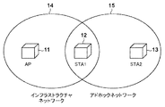
図1は実施形態1の第1の通信装置(以下、STA1)、アクセスポイント(以下、AP)および第2の通信装置(以下、STA2)、第3の通信装置(STA3)を含むネットワークシステムの構成を示す図である。
<Embodiment 1>
FIG. 1 shows a network system including a first communication device (hereinafter referred to as STA1), an access point (hereinafter referred to as AP), a second communication device (hereinafter referred to as STA2), and a third communication device (STA3) according to the first embodiment. It is a figure which shows a structure.
11はAPであり、無線LANのインフラストラクチャネットワーク14を構成し、管理している。APはWANに接続しており、インフラストラクチャネットワーク14配下の端末はAPを介してWANでの通信が可能である。
12はインフラストラクチャモードとアドホックモードの両方の機能を同時動作可能なSTA1であり、インフラストラクチャモードでインフラストラクチャネットワーク14に接続している。また、STA1はアドホックモードでアドホックネットワーク15を構成している。
13はSTA2であり、STA1と同様にアドホックネットワーク15を構成している。インフラストラクチャネットワーク14とアドホックネットワーク15は独立して動作しており、ネットワーク識別子(以下、SSID)、認証方式、暗号方式等は異なっていてもよい。
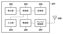
図2は通信装置12(STA1)の構成の一例を示す機能ブロック図である。 FIG. 2 is a functional block diagram showing an example of the configuration of the communication device 12 (STA1).
201は装置全体を示す。202は各種表示を行う表示部であり、LCDやLEDのように視覚で認知可能な情報の出力、あるいはスピーカ等の音出力が可能な機能を有する。203は記憶部204に記憶される制御プログラムを実行することにより装置全体を制御する制御部である。204は制御部203が実行する制御プログラムを記憶する記憶部である。後述する各種動作は、記憶部204に記憶された制御プログラムを制御部203が実行することにより行われる。205は後述するネットワークの端末制限数をユーザが指示するための入力部である。206は無線通信を行うための無線部である。無線部206には、インフラストラクチャモード用の通信IFと、アドホッネットワーク用の通信IFが搭載されている。207はアンテナ制御部である。また、208はアンテナ制御部207により制御されるアンテナである。
このように、通信装置12は、第1の通信インターフェースと第2の通信インターフェースを含む複数の通信インターフェースを有し、それぞれの通信インターフェースでネットワークに接続する通信装置である。また、第1の通信インターフェースには第1のIPアドレスが設定され、第2の通信インターフェースには第1のIPアドレスとは異なる第2のIPアドレスが設定される。尚、第1のIPアドレスと第2のIPアドレスが重複する場合には、第1のIPアドレスと第2のIPアドレスとは異なる第3のIPアドレスが一方の通信インターフェースに設定される。
As described above, the
尚、通信装置11(AP)と通信装置13(STA2)の構成も、図2の同様の構成を有しているが、無線部では、必要な通信IFを実装している。 Note that the configurations of the communication device 11 (AP) and the communication device 13 (STA2) also have the same configuration as in FIG. 2, but the wireless unit has a necessary communication IF.
図3は制御部203が実行するソフトウェア機能ブロックの構成の一例を示すブロック図である。
FIG. 3 is a block diagram showing an example of the configuration of software function blocks executed by the
301は、無線部206を制御するための無線制御部である。無線制御部301において、304は、インフラストラクチャモードの無線通信を制御するインフラストラクチャモード制御部である。305は、アドホックモードの無線通信を制御するアドホックモード制御部である。
302は、Internet Protocol(以下、IP)のアドレッシングを制御するためのアドレッシング制御部である。アドレッシング制御部302において、306は、通信IFに割り当てるIPアドレスを所定の方法で生成するためのIPアドレス生成部である。307は、Dynamic Host Configuration Protocol(以下、DHCP)のプロトコル処理を行うDHCP処理部である。308は、AutoIPのプロトコル処理を行うAutoIP処理部である。309は、機器内でIPアドレスが重複しないか否かを判定するための重複判定部である。310は、重複判定部309で重複すると判定された場合に、異なるIPアドレスを取得するためのIPアドレス再取得部である。
303は、IPの通信制御を行うIP制御部である。IP制御部303において、311は、通信で用いるパケットを受信するパケット受信部である。312は、通信で用いるパケットを送信するパケット送信部である。313は、通信IFに対してIPアドレスを登録するIPアドレス登録部である。314は、通信IFのIPアドレスを削除するIPアドレス削除部である。
An
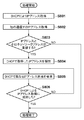
図4は通信装置12(STA1)のIPアドレス自動割当の処理を示すフローチャートである。 FIG. 4 is a flowchart showing the IP address automatic assignment process of the communication apparatus 12 (STA1).
STA1は、無線制御部301によって、他の通信IFに設定されているIPアドレスを取得する(ステップS401)。STA1は、重複判定部309によって、取得したIPアドレスと、IPアドレスが未設定の通信IFに設定する、AutoIPで生成される仮IPアドレスが重複するか否かを判定する(ステップS402)。判定方法としては、仮IPアドレスを所定の方法で生成した結果との比較で行うことでも可能であるし、MACアドレスが同一の他の通信IFにリンクローカルアドレスとして設定されていることで重複すると判定してもよい。 The STA1 acquires an IP address set in another communication IF by the wireless control unit 301 (step S401). The STA1 determines whether or not the acquired IP address and the temporary IP address generated by AutoIP set in the communication IF in which the IP address is not set are overlapped by the overlap determining unit 309 (step S402). As a determination method, it is possible to compare the result of generating a temporary IP address with a result generated by a predetermined method, and if the MAC address is duplicated because it is set as a link local address in the same other communication IF You may judge.
仮IPアドレスと重複すると判定した場合(ステップS402でYES)、STA1は、IPアドレス再取得部310によって、仮IPアドレスを生成するためのシードを変更する(ステップS403)。シードの変更方法としては、一般的に使用される通信IFのMACアドレスのG/Lビットを反転することで実現可能であるし、その他の方法を用いてもよい。次に、STA1は、IPアドレス生成部306によって、変更したシードを用いて仮IPアドレスを生成する(ステップS404)。 If it is determined that the IP address overlaps with the temporary IP address (YES in step S402), the STA1 changes the seed for generating the temporary IP address by the IP address reacquisition unit 310 (step S403). The seed change method can be realized by inverting the G / L bit of the MAC address of the communication IF that is generally used, or other methods may be used. Next, the STA1 generates a temporary IP address by using the changed seed by the IP address generation unit 306 (step S404).
一方、仮IPアドレスが重複しないと判定した場合(ステップS402でNO)、STA1は、IPアドレス生成部306によって、シードを変更することなく仮IPアドレスを生成する(ステップS404)。 On the other hand, when it is determined that the temporary IP addresses do not overlap (NO in step S402), the STA1 generates a temporary IP address without changing the seed by the IP address generation unit 306 (step S404).
仮IPアドレスを生成すると、STA1は、AutoIP処理部308によって、同一のIPアドレスがネットワーク内で使用されてないか重複判定処理を行う(ステップS407)。この方法は、AutoIPのプロトコルに従って実行可能であるし、その他の方法を用いてもよい。
When the temporary IP address is generated, the STA1 performs duplication determination processing by using the
処理が終了すると、STA1は、IPアドレス登録部313によって、通信IFにIPアドレスを設定し、その通信IFを用いてデータ通信が可能な状態となる。
When the processing is completed, the STA 1 sets an IP address in the communication IF by the IP
図5はAPが構築するインフラストラクチャネットワークにSTA1が接続しており、STA2がアドホックネットワークを構成した状態でSTA1がアドホックネットワークに接続し、IPアドレス自動割当を実行する場合のシーケンス図である。 FIG. 5 is a sequence diagram when the STA1 is connected to the infrastructure network constructed by the AP, the STA1 connects to the ad hoc network in a state where the STA2 configures the ad hoc network, and IP address automatic assignment is executed.
ここで、APのIPアドレスには「192.168.1.1」が設定されており、STA1のインフラストラクチャモードの通信IFには「169.254.11.22」が設定されている。また、アドホッネットワーク内のSTA2のIPアドレスには「169.254.33.44」が設定されている。 Here, “192.168.1.1” is set in the IP address of the AP, and “169.2544.111.22” is set in the communication IF in the infrastructure mode of the STA1. Further, “169.254.33.44” is set as the IP address of STA2 in the ad hoc network.
STA1は、アドホックモード制御部305によって、アドホックネットワークへの無線接続処理を実行する(F501)。
The STA1 uses the ad hoc
次に、STA1は、インフラストラクチャモード制御部304によって、インフラストラクチャモードの通信IFに割り当てられたIPアドレスを取得する(F502)。この例では「169.254.11.22」が取得される。 Next, the STA1 acquires the IP address assigned to the infrastructure mode communication IF by the infrastructure mode control unit 304 (F502). In this example, “169.2544.111.22” is acquired.
STA1は、IPアドレス生成部306によって、アドホックモードの通信IFのMACアドレスを用いて所定の方法で仮IPアドレスを生成する。この生成された仮IPアドレスが「169.254.11.22」であるとすると、STA1は、重複判定部309によって、設定されているIPアドレスと重複すると判定する(F503)。STA1は、IPアドレス再取得部310によって、仮IPアドレスのシードとして用いるMACアドレスの値を変更する(F504)。この時、実際の通信IFのMACアドレスは変更する必要はない。
The STA 1 uses the IP
STA1は、IPアドレス生成部306によって、変更されたシードを用いて仮IPアドレスを生成する(F505)。この例では、「169.254.55.66」を生成する。仮IPアドレスが生成されると、STA1は、AutoIP処理部308によって、AutoIPのプロトコルに従って重複判定処理を行う(F506)。
The STA1 uses the IP
重複判定処理によりネットワーク内での重複がないことを確認すると、STA1は、IPアドレス登録部313によって、生成した仮IPアドレスをアドホックモードの通信IFに設定する。一方、重複判定処理によりネットワーク内での重複があることを確認すると、STA1は、従前に生成した仮IPアドレスとは異なる仮IPアドレスを生成して、再度、重複判定処理を実行し、重複がないことが確認されるまで、仮IPアドレスの生成を繰り返す。
When the duplication determination process confirms that there is no duplication in the network, the STA 1 sets the generated temporary IP address in the ad hoc mode communication IF by the IP
以上説明したように、実施形態1によれば、AutoIPで生成される仮IPアドレスがその他の通信IFに設定されているIPアドレスと重複する場合は、異なる仮IPアドレスを使用するように制御する。そのため、AutoIPにおいて複数の通信IFに同一IPアドレスが設定されることを防止することが可能となる。 As described above, according to the first embodiment, when a temporary IP address generated by AutoIP overlaps with an IP address set in another communication IF, control is performed to use a different temporary IP address. . Therefore, it is possible to prevent the same IP address from being set in a plurality of communication IFs in AutoIP.
<実施形態2>
尚、実施形態2におけるネットワークシステムの構成、通信装置の構成は、図1乃至図3を用いて説明した実施形態1と同じであり、説明は省略する。
<Embodiment 2>
The configuration of the network system and the configuration of the communication device in the second embodiment are the same as those in the first embodiment described with reference to FIGS.
実施形態2では、STA1がインフラストラクチャモードの通信IFでDHCPによりIPアドレス自動割当を行う場合の動作について説明する。 In the second embodiment, an operation when the STA 1 performs automatic IP address assignment by DHCP in the infrastructure mode communication IF will be described.
図6は通信装置12(STA1)のIPアドレス自動割当の処理を示すフローチャートである。 FIG. 6 is a flowchart showing the IP address automatic assignment process of the communication apparatus 12 (STA1).
STA1は、DHCP処理部307によって、DHCPサーバよりIPアドレスを取得する(ステップS601)。DHCP処理部307では、DHCPクライアントがDHCPサーバに対して初回の問い合わせをする場合、DHCPサーバが配布するIPアドレスの範囲を知ることができない。そのため、一般的には任意(ANY)のIPアドレスを要求する。ステップS601においても同様に任意のIPアドレスを要求することで実施可能である。
The STA1 acquires an IP address from the DHCP server by the DHCP processing unit 307 (step S601). When the DHCP client makes an initial inquiry to the DHCP server, the
次に、STA1は、無線制御部301によって、DHCPを実行した通信IF以外の、IPアドレスが未設定の通信IFのIPアドレスを取得する(ステップS602)。STA1は、重複判定部309によって、ステップS601で取得したIPアドレスとステップS602で取得したIPアドレスが重複するか否かを判定する(ステップS603)。
Next, the STA1 uses the
IPアドレスが重複しないと判定した場合(ステップS603でNO)、STA1は、処理を終了し、DHCPで取得したIPアドレスを通信IFに設定する。 If it is determined that the IP addresses do not overlap (NO in step S603), the STA1 ends the process and sets the IP address acquired by DHCP as the communication IF.
一方、IPアドレスが重複すると判定した場合(ステップS603でYES)、STA1は、DHCP処理部307によって、ステップS601で取得した(DHCPでリースされた)IPアドレスを解放する(ステップS604)。解放する方法としては、DHCP ReleaseパケットをDHCPサーバに送信することで可能である。 On the other hand, when it is determined that the IP addresses are duplicated (YES in step S603), the STA1 releases the IP address acquired in step S601 (leased by DHCP) by the DHCP processing unit 307 (step S604). As a release method, a DHCP Release packet can be transmitted to the DHCP server.
ステップS601で取得した(DHCPでリースされた)IPアドレスを解放したら、STA1は、DHCP処理部307によって、ステップS601で取得したIPアドレスとは異なるIPアドレスの取得を要求する(ステップS605)。IPアドレスを要求する方法としては、再度DHCPによる自動割当処理を行う場合にDHCP Requestパケットに要求するIPアドレスをセットすることで可能である。
After releasing the IP address acquired in step S601 (leased by DHCP), the STA1 requests the
次に、STA1は、重複判定部309によって、ステップS605で要求したIPアドレスの取得に成功したか否かを判定する(ステップS606)。取得に失敗した場合(ステップS606でNO)、ステップS605に戻る。一方、取得に成功した場合(ステップS606でYES)、STA1は、処理を終了し、IPアドレス登録部313によって、ステップS606で取得したIPアドレスを通信IFに設定する。
Next, the STA1 determines whether or not the
図7は、STA1とSTA2がアドホックネットワークを構成し、APが構築するインフラストラクチャネットワークにSTA1が接続し、IPアドレス自動割当を実行する場合のシーケンス図である。 FIG. 7 is a sequence diagram when STA1 and STA2 constitute an ad hoc network, STA1 is connected to an infrastructure network constructed by an AP, and IP address automatic assignment is executed.
APのIPアドレスは「192.168.1.1」が設定されており、APが内蔵のDHCPサーバを有しており、インフラストラクチャネットワークではDHCPによるIPアドレス自動割当が可能である。また、アドホックネットワークでは、STA2のIPアドレスは「192.168.1.3」が、STA1のIPアドレスは「192.168.1.4」が設定されている。 The IP address of the AP is set to “192.168.1.1”, the AP has a built-in DHCP server, and the IP address can be automatically assigned by DHCP in the infrastructure network. In the ad hoc network, the IP address of STA2 is set to “192.168.1.3”, and the IP address of STA1 is set to “192.168.1.4”.
STA1は、インフラストラクチャモード制御部304によって、インフラストラクチャネットワークへの無線接続処理を実行する(F701)。接続すると、STA1は、DHCP処理部307によって、DHCPによるIPアドレス自動割当処理を行う(F702)。この例では、DHCP処理部307(F702)で「192.168.1.4」のIPアドレスを取得する。DHCP処理が完了すると、STA1は、アドホックモード制御部305によって、アドホックモードのIPアドレスを取得する。この例では「192.168.1.4」というIPアドレスを取得する。
The STA1 uses the infrastructure
次に、STA1は、重複判定部309によって、F702で取得したIPアドレスとF703で取得したIPアドレスを比較して、重複するか否かを判定する(F704)。
Next, the STA1 compares the IP address acquired in F702 with the IP address acquired in F703 by using the
判定の結果、STA1は、IPアドレスが重複すると判定すると、DHCP処理部307によって、F702で取得したIPアドレスを解放するためにDHCP ReleaseパケットをAPに送信する(F705)。
As a result of the determination, if the STA1 determines that the IP addresses are duplicated, the
次に、STA1は、IPアドレス再取得部310によって、再度DHCPによる自動割当を行う場合に要求するIPアドレスを決定する(F706)。要求するIPアドレスの決定方法としては、F702で取得したIPアドレス情報(例えば、IPアドレスが「192.168.1.4」、ネットマスクが「255.255.255.0」、オプション情報)から決定することが可能である。 Next, the STA1 determines the IP address to be requested when automatic allocation by DHCP is performed again by the IP address reacquisition unit 310 (F706). As a method for determining the requested IP address, from the IP address information acquired in F702 (for example, the IP address is “192.168.1.4”, the netmask is “255.255.255.0”, option information). It is possible to determine.
例えば、このIPアドレス情報からこのネットワークで利用可能なIPアドレスは「192.168.1.1」〜「192.168.1.255」であることが判定できる。また、DHCPサーバ(この例ではAP)には「192.168.1.1」が設定されており、F701で取得したIPアドレスは「192.168.1.4」であるため、これらのIPアドレスは対象外となる。その他、DNSサーバのIPアドレス、ゲートウェイのIPアドレス等をIPアドレス情報として取得した場合も対象外とできる。 For example, it can be determined from this IP address information that the IP addresses available on this network are “192.168.1.1” to “192.168.1.255”. Further, since “192.168.1.1” is set in the DHCP server (AP in this example) and the IP address acquired in F701 is “192.168.1.4”, these IP addresses are set. Address is excluded. In addition, when the IP address of the DNS server, the IP address of the gateway, etc. are acquired as IP address information, it can be excluded.
F706では、「192.168.1.5」を再度要求するIPアドレスとして決定したものとする。STA1は、要求するIPアドレスを決定すると、DHCP処理部307によって、DHCP Requestパケットに要求するIPアドレスをセットして、そのDHCP RequestパケットをDHCPサーバに送信する(F707)。
In F706, “192.168.1.5” is determined as the IP address to be requested again. When the STA1 determines the requested IP address, the
APは、DHCP Requestパケットを受信すると、要求されたIPアドレスが解放可能であることを確認し、DCHP ACKをSTA1に送信する(F708)。 Upon receiving the DHCP Request packet, the AP confirms that the requested IP address can be released and transmits a DCHP ACK to STA1 (F708).
STA1は、DHCPによるIPアドレスの取得に成功すると、IPアドレス登録部313によって、そのIPアドレスをインフラストラクチャモードの通信IFに設定する。
When the STA1 succeeds in acquiring an IP address by DHCP, the IP
以上説明したように、実施形態2によれば、DHCPで取得したIPアドレスが他の通信IFに設定されたIPアドレスと重複する場合は、そのIPアドレスを解放して異なるIPアドレスを再取得する。そのため、DHCPでIPアドレスを設定する場合に複数の通信IFに同一IPアドレスが設定されることを防止することが可能となる。 As described above, according to the second embodiment, when an IP address acquired by DHCP overlaps with an IP address set in another communication IF, the IP address is released and a different IP address is acquired again. . Therefore, it is possible to prevent the same IP address from being set in a plurality of communication IFs when setting the IP address by DHCP.
<実施形態3>
尚、実施形態3におけるネットワークシステムの構成、通信装置の構成は図1乃至図3を用いて説明した実施形態1と同じであり、説明は省略する。
<Embodiment 3>
The configuration of the network system and the configuration of the communication device in the third embodiment are the same as those in the first embodiment described with reference to FIGS.
実施形態3では、STA1がインフラストラクチャモードの通信IFでDHCPによりIPアドレス自動割当を行う場合の動作について説明する。 In the third embodiment, an operation when the STA 1 performs automatic IP address assignment by DHCP in the infrastructure mode communication IF will be described.
図8は通信装置12(STA1)のIPアドレス自動割当の処理を示すフローチャートである。 FIG. 8 is a flowchart showing the IP address automatic assignment process of the communication apparatus 12 (STA1).
尚、ステップS801、ステップS802、ステップS804及びステップS806の処理は、図6のステップS601、ステップS602、ステップS604及びステップS806と同様であるため、説明は省略する。 Note that the processing of step S801, step S802, step S804, and step S806 is the same as step S601, step S602, step S604, and step S806 of FIG.
STA1は、重複判定部309によって、ステップS801で取得したIPアドレスとそのネットワークアドレスがステップS802で取得したIPアドレスとそのネットワークアドレスと重複するか否かを判定する(ステップS803)。IPアドレスとそのネットワークアドレスが重複しないと判定した場合(ステップS803でNO)、STA1は、処理を終了し、IPアドレス登録部313によって、DHCPで取得したIPアドレスを通信IFに設定する。
The STA1 determines whether or not the IP address acquired in step S801 and its network address overlap the IP address acquired in step S802 and the network address by the duplication determination unit 309 (step S803). If it is determined that the IP address and its network address do not overlap (NO in step S803), the STA1 ends the process, and the IP
一方、IPアドレスとそのネットワークアドレスが重複すると判定した場合(ステップS803でYES)、STA1は、ステップS804の処理を経て、IPアドレス再取得部310によって、ステップS801で取得したIPアドレスとは異なるIPアドレスの取得を要求する(ステップS805)。ステップS805では、ネットワークアドレスの重複が回避可能と判定した場合は、異なるネットワークアドレスのIPアドレスを要求するように制御する。例えば、ステップS802で取得したIPアドレスが「192.168.1.4/24」、ステップS801で取得したIPアドレスが「192.168.1.4/16」である場合、「192.168.2.1」〜「192.168.255.255」を要求する。
On the other hand, if it is determined that the IP address and its network address overlap (YES in step S803), the STA1 performs an IP address different from the IP address acquired in step S801 by the IP
その後、ステップS806の処理を実行する。 Thereafter, the process of step S806 is executed.
図9は、STA1とSTA2がアドホックネットワークを構成し、APが構築するインフラストラクチャネットワークにSTA1が接続し、IPアドレス自動割当を実行する場合のシーケンス図である。 FIG. 9 is a sequence diagram in the case where STA1 and STA2 constitute an ad hoc network, STA1 is connected to an infrastructure network constructed by an AP, and automatic IP address assignment is executed.
APのIPアドレスは「192.168.1.1/16」が設定されており、APが内蔵のDHCPサーバを有しており、インフラストラクチャネットワークではDHCPによるIPアドレス自動割当が可能である。また、アドホックネットワークでは、STA2のIPアドレスは「192.168.1.3/24」が、STA1のIPアドレスは「192.168.1.4/24」が設定されている。 The IP address of the AP is set to “192.168.1.1/16”, the AP has a built-in DHCP server, and the IP address can be automatically assigned by DHCP in the infrastructure network. In the ad hoc network, the IP address of STA2 is set to “192.168.1.3/24”, and the IP address of STA1 is set to “192.168.1.4/24”.
F901乃至F903の処理は、図7のF701乃至F703と同様であるため、説明は省略する。但し、F902ではIPアドレス情報として「192.168.1.4/16」を取得し、F903では「192.168.1.4/24」を取得したものとする。 Since the processing of F901 to F903 is the same as that of F701 to F703 of FIG. However, it is assumed that “192.168.1.4/16” is acquired as the IP address information in F902, and “192.168.1.4/24” is acquired in F903.
次に、STA1は、重複判定部309によって、F902で取得したIPアドレスとそのネットワークアドレスと、F903で取得したIPアドレスとそのネットワークアドレスを比較して、重複するか否かを判定する(F904)。
Next, the STA1 compares the IP address acquired in F902 and its network address with the IP address acquired in F903 and the network address by the
判定の結果、STA1はIPアドレス及びネットワークアドレスが重複すると判定すると、STA1は、DHCP処理部307によって、F902で取得したIPアドレスを解放するためにDHCP ReleaseパケットをAPに送信する(F905)。
If the STA1 determines that the IP address and the network address overlap as a result of the determination, the STA1 transmits a DHCP Release packet to the AP by the
次に、STA1は、IPアドレス再取得部310によって、再度DHCPによる自動割当を行う場合に要求するIPアドレスを決定する(F906)。要求するIPアドレスの決定方法としては、F902で取得したIPアドレス情報(例えば、IPアドレスが「192.168.1.4」、ネットマスクが「255.255.0.0」、オプション情報)から決定することが可能である。 Next, the STA1 determines the IP address to be requested when automatic allocation by DHCP is performed again by the IP address reacquisition unit 310 (F906). As a method for determining the requested IP address, from the IP address information acquired in F902 (for example, the IP address is “192.168.1.4”, the netmask is “255.255.0.0”, option information). It is possible to determine.
例えば、このIPアドレス情報からこのネットワークで利用可能なIPアドレスは「192.168.0.0」〜「192.168.255.255」のアドレス空間の範囲内であることが判定できる。また、F903で取得したIPアドレス情報から「192.168.1.0」〜「192.168.1.255」のアドレス空間を対象外(範囲外)とする。 For example, from this IP address information, it can be determined that the IP address that can be used on this network is within the address space of “192.168.0.0” to “192.168.255.255”. Further, the address space from “192.168.1.0” to “192.168.1.255” is excluded (out of range) from the IP address information acquired in F903.
F906では、「192.168.2.2/16」を再度要求するIPアドレスとして決定したものとする。STA1は、要求するIPアドレスを決定すると、F707と同様に、DHCP処理部307によって、DHCP RequestパケットをDHCPサーバに送信する(F907)。
In F906, “192.168.2.2/16” is determined as the IP address to be requested again. When the STA1 determines the requested IP address, the
APは、F708と同様に、DCHP ACKをSTA1に送信する(F908)。 The AP transmits a DCHP ACK to STA1 as in F708 (F908).
STA1は、DHCPによるIPアドレスの取得に成功すると、IPアドレス登録部313によって、そのIPアドレスをインフラストラクチャモードの通信IFに設定する。
When the STA1 succeeds in acquiring an IP address by DHCP, the IP
以上説明したように、実施形態3によれば、DHCPで取得したネットワークアドレスが他の通信IFに設定されたネットワークアドレスと重複する場合は、そのIPアドレスを解放して異なるIPアドレスを再取得する。そのため、DHCPでIPアドレスを設定する場合に複数の通信IFに同一ネットワークアドレスのIPアドレスが設定されることを防止することが可能となる。 As described above, according to the third embodiment, when a network address acquired by DHCP overlaps with a network address set in another communication IF, the IP address is released and a different IP address is acquired again. . Therefore, when an IP address is set by DHCP, it is possible to prevent an IP address having the same network address from being set in a plurality of communication IFs.
<実施形態4>
尚、実施形態4におけるネットワークシステムの構成、通信装置の構成は図1乃至図3を用いて説明した実施形態1と同じであり、説明は省略する。
<Embodiment 4>
The configuration of the network system and the configuration of the communication apparatus in the fourth embodiment are the same as those in the first embodiment described with reference to FIGS.
実施形態4では、STA1がインフラストラクチャモードの通信IFでDHCPによりIPアドレス自動割当を行う場合の動作について説明する。また、STA1は過去にAPからDHCPによりIPアドレスを取得しており、一度、ネットワークから離脱して再度接続する場合の動作について説明する。 In the fourth embodiment, an operation when the STA 1 performs automatic IP address assignment by DHCP in the infrastructure mode communication IF will be described. The operation when the STA1 has acquired an IP address by DHCP from the AP in the past and once disconnects from the network and reconnects will be described.
STA1は過去にDHCPで取得したIPアドレスをIPアドレス登録部313に記憶しており、重複判定部309によって、そのIPアドレスがアドホックモードのIPアドレスと同一でないかを判定する。判定の結果、異なるIPアドレスと判定された場合は過去に取得したIPアドレスをDHCPで要求する。また、同一のIPアドレスを取得した場合は異なるIPアドレスをDHCPで要求する。
The STA1 stores the IP address obtained by DHCP in the past in the IP
以上説明したように、実施形態4によれば、過去に取得したIPアドレスを再度DHCPで取得しようとする前に他の通信IFのIPアドレスとの重複を判定し、重複する場合は異なるIPアドレスを要求する。そのため、重複判定の結果、2回目のIPアドレス取得処理(IPアドレス再取得処理)を実行する必要がなくなり、IPアドレス設定完了までの時間を短縮することが可能となる。 As described above, according to the fourth embodiment, before an IP address acquired in the past is acquired again by DHCP, the IP address of another communication IF is determined to be duplicated. Request. Therefore, as a result of the duplication determination, it is not necessary to execute the second IP address acquisition process (IP address reacquisition process), and it is possible to shorten the time until the IP address setting is completed.
尚、本発明は、以下の処理を実行することによっても実現される。即ち、上述した実施形態の機能を実現するソフトウェア(プログラム)を、ネットワーク又は各種記憶媒体を介してシステムまたは装置に供給し、そのシステムまたは装置のコンピュータ(またはCPUやMPU等)がプログラムを読み出して実行する処理である。 The present invention can also be realized by executing the following processing. That is, software (program) that realizes the functions of the above-described embodiments is supplied to a system or apparatus via a network or various storage media, and a computer (or CPU, MPU, or the like) of the system or apparatus reads the program. It is a process to be executed.
Claims (12)
第1の無線ネットワークにおいて前記通信装置が利用する第1のアドレスを設定する第1の設定手段と、
前記第1の無線ネットワークへ参加し、当該第1の無線ネットワークへの参加を維持したまま、当該第1の無線ネットワークとは異なる第2の無線ネットワークへ新たに参加する参加手段と、
前記参加手段により前記第2の無線ネットワークへ新たに参加する際に、前記第1のアドレスのネットワークアドレス部分と、前記第2の無線ネットワークにおいて前記通信装置が利用しようとしている第1のネットワークアドレスとが共通しているかを判定する判定手段と、
前記判定手段の判定の結果に応じて、前記第2の無線ネットワークにおいて前記通信装置が利用する第2のアドレスを設定する第2の設定手段と、
を有し、
前記第2の設定手段は、前記第1のアドレスのネットワークアドレス部分と前記第1のネットワークアドレスとが共通している場合、前記第1の無線ネットワークにおいて前記通信装置が利用するアドレスを前記第1の設定手段によって設定された前記第1のアドレスから変更することなく、前記第2のアドレスとして、前記第1のネットワークアドレスと異なる第2のネットワークアドレスを利用したアドレスを設定し、
前記第2の設定手段は、前記第1のアドレスのネットワークアドレス部分と前記第1のネットワークアドレスとが共通していない場合、前記第1の無線ネットワークにおいて前記通信装置が利用するアドレスを前記第1の設定手段によって設定された前記第1のアドレスから変更することなく、前記第2のアドレスとして、前記第1のネットワークアドレスを利用したアドレスを設定する、
ことを特徴とする通信装置。 A communication device,
First setting means for setting a first address used by the communication device in a first wireless network ;
Participating means for newly joining a second wireless network different from the first wireless network while joining the first wireless network and maintaining participation in the first wireless network;
When newly joining the second wireless network by the joining means, a network address portion of the first address, and a first network address that the communication device intends to use in the second wireless network, There determination means for determining whether the common,
A second setting unit configured to set a second address used by the communication device in the second wireless network according to a determination result of the determination unit;
Have
When the network address part of the first address and the first network address are common, the second setting means sets an address used by the communication device in the first wireless network. Without changing from the first address set by the setting means, an address using a second network address different from the first network address is set as the second address,
When the network address part of the first address and the first network address are not common, the second setting means sets an address used by the communication device in the first wireless network. An address using the first network address is set as the second address without changing from the first address set by the setting means .
A communication device.
第1の無線ネットワークにおいて前記通信装置が利用する第1のアドレスを設定する第1の設定手段と、 First setting means for setting a first address used by the communication device in a first wireless network;
前記第1の無線ネットワークへ参加し、当該第1の無線ネットワークへの参加を維持したまま、当該第1の無線ネットワークとは異なる第2の無線ネットワークへ新たに参加する参加手段と、 Participating means for newly joining a second wireless network different from the first wireless network while joining the first wireless network and maintaining participation in the first wireless network;
前記参加手段により前記第2の無線ネットワークへ新たに参加する際に、前記第1のアドレスと、前記第2の無線ネットワークにおいて前記通信装置が利用しようとしている第3のアドレスとが共通しているかを判定する判定手段と、 Whether the first address and a third address that the communication device intends to use in the second wireless network are common when the joining means newly joins the second wireless network Determining means for determining
前記判定手段の判定の結果に応じて、前記第2の無線ネットワークにおいて前記通信装置が利用する第2のアドレスを設定する第2の設定手段と、 A second setting unit configured to set a second address used by the communication device in the second wireless network according to a determination result of the determination unit;
を有し、 Have
前記第2の設定手段は、前記第1のアドレスと前記第3のアドレスとが共通している場合、前記第1の無線ネットワークにおいて前記通信装置が利用するアドレスを前記第1の設定手段によって設定された前記第1のアドレスから変更することなく、前記第2のアドレスとして、前記第3のアドレスとは異なるアドレスを設定し、 The second setting means sets, by the first setting means, an address used by the communication device in the first wireless network when the first address and the third address are common. Without changing from the first address that has been made, the second address is set as an address different from the third address,
前記第2の設定手段は、前記第1のアドレスと前記第3のアドレスとが共通していない場合、前記第1の無線ネットワークにおいて前記通信装置が利用するアドレスを前記第1の設定手段によって設定された前記第1のアドレスから変更することなく、前記第2のアドレスとして、前記第3のアドレスを設定する、 The second setting means sets, by the first setting means, an address used by the communication device in the first wireless network when the first address and the third address are not common. The third address is set as the second address without changing from the first address
ことを特徴とする通信装置。 A communication device.
ことを特徴とする請求項2に記載の通信装置。 The communication device according to claim 2.
ことを特徴とする請求項1または2に記載の通信装置。 The communication apparatus according to claim 1 or 2, wherein
ことを特徴とする請求項1から4のいずれか1項に記載の通信装置。 The communication apparatus according to any one of claims 1 to 4, wherein the communication apparatus is characterized in that:
ことを特徴とする請求項1から5のいずれか1項に記載の通信装置。 The communication apparatus according to any one of claims 1 to 5, wherein:
ことを特徴とする請求項1から6のいずれか1項に記載の通信装置。 The communication apparatus according to claim 1, wherein
ことを特徴とする請求項1から7のいずれか1項に記載の通信装置。 The communication device according to claim 1, wherein the communication device is a device.
前記第2の無線ネットワークと接続する第2の通信インターフェースと、 A second communication interface connected to the second wireless network;
をさらに有することを特徴とする請求項1から8のいずれか1項に記載の通信装置。 The communication apparatus according to claim 1, further comprising:
第1の無線ネットワークにおいて前記通信装置が利用する第1のアドレスを設定する第1の設定工程と、
前記第1の無線ネットワークへ参加し、当該第1の無線ネットワークへの参加を維持したまま、当該第1の無線ネットワークとは異なる第2の無線ネットワークへ新たに参加する参加工程と、
前記参加工程において前記第2の無線ネットワークへ新たに参加する際に、前記第1のアドレスのネットワークアドレス部分と、前記第2の無線ネットワークにおいて前記通信装置が利用しようとしている第1のネットワークアドレスとが共通しているかを判定する判定工程と、
前記判定工程における判定の結果に応じて、前記第2の無線ネットワークにおいて前記通信装置が利用する第2のアドレスを設定する第2の設定工程と、
を有し、
前記第2の設定工程では、前記第1のアドレスのネットワークアドレス部分と前記第1のネットワークアドレスとが共通している場合、前記第1の無線ネットワークにおいて前記通信装置が利用するアドレスを前記第1の設定工程において設定された前記第1のアドレスから変更することなく、前記第2のアドレスとして、前記第1のネットワークアドレスと異なる第2のネットワークアドレスを利用したアドレスを設定し、
前記第2の設定工程では、前記第1のアドレスのネットワークアドレス部分と前記第1のネットワークアドレスとが共通していない場合、前記第1の無線ネットワークにおいて前記通信装置が利用するアドレスを前記第1の設定工程において設定された前記第1のアドレスから変更することなく、前記第2のアドレスとして、前記第1のネットワークアドレスを利用したアドレスを設定する、
ことを特徴とする制御方法。 A communication device control method comprising:
A first setting step of setting a first address where the communication apparatus is utilized in the first wireless network,
Participating in the first wireless network and joining the second wireless network different from the first wireless network while maintaining participation in the first wireless network;
When newly joining the second wireless network in the joining step, a network address portion of the first address, and a first network address that the communication device intends to use in the second wireless network, A determination process for determining whether or not
A second setting step of setting a second address used by the communication device in the second wireless network according to a result of the determination in the determination step;
Have
In the second setting step, when the network address part of the first address and the first network address are common, the address used by the communication device in the first wireless network is the first address. Without changing from the first address set in the setting step, as the second address, an address using a second network address different from the first network address,
In the second setting step, if the network address part of the first address and the first network address are not common, the address used by the communication device in the first wireless network is the first address. An address using the first network address is set as the second address without changing from the first address set in the setting step .
A control method characterized by that .
第1の無線ネットワークにおいて前記通信装置が利用する第1のアドレスを設定する第1の設定工程と、 A first setting step of setting a first address used by the communication device in a first wireless network;
前記第1の無線ネットワークへ参加し、当該第1の無線ネットワークへの参加を維持したまま、当該第1の無線ネットワークとは異なる第2の無線ネットワークへ新たに参加する参加工程と、 Participating in the first wireless network and joining the second wireless network different from the first wireless network while maintaining participation in the first wireless network;
前記参加工程において前記第2の無線ネットワークへ新たに参加する際に、前記第1のアドレスと、前記第2の無線ネットワークにおいて前記通信装置が利用しようとしている第3のアドレスとが共通しているかを判定する判定工程と、 Whether the first address and the third address that the communication device intends to use in the second wireless network are common when newly joining the second wireless network in the joining step A determination step of determining
前記判定工程における判定の結果に応じて、前記第2の無線ネットワークにおいて前記通信装置が利用する第2のアドレスを設定する第2の設定工程と、 A second setting step of setting a second address used by the communication device in the second wireless network according to a result of the determination in the determination step;
を有し、 Have
前記第2の設定工程では、前記第1のアドレスと前記第3のアドレスとが共通している場合、前記第1の無線ネットワークにおいて前記通信装置が利用するアドレスを前記第1の設定工程において設定された前記第1のアドレスから変更することなく、前記第2のアドレスとして、前記第3のアドレスとは異なるアドレスを設定し、 In the second setting step, when the first address and the third address are common, the address used by the communication device in the first wireless network is set in the first setting step. Without changing from the first address that has been made, the second address is set as an address different from the third address,
前記第2の設定工程では、前記第1のアドレスと前記第3のアドレスとが共通していない場合、前記第1の無線ネットワークにおいて前記通信装置が利用するアドレスを前記第1の設定工程において設定された前記第1のアドレスから変更することなく、前記第2のアドレスとして、前記第3のアドレスを設定する、 In the second setting step, when the first address and the third address are not common, the address used by the communication device in the first wireless network is set in the first setting step. The third address is set as the second address without changing from the first address
ことを特徴とする制御方法。 A control method characterized by that.
Priority Applications (2)
| Application Number | Priority Date | Filing Date | Title |
|---|---|---|---|
| JP2012125145A JP5950699B2 (en) | 2012-05-31 | 2012-05-31 | COMMUNICATION DEVICE AND ITS CONTROL METHOD |
| US13/869,651 US9712487B2 (en) | 2012-05-31 | 2013-04-24 | Communication apparatus and method of controlling same |
Applications Claiming Priority (1)
| Application Number | Priority Date | Filing Date | Title |
|---|---|---|---|
| JP2012125145A JP5950699B2 (en) | 2012-05-31 | 2012-05-31 | COMMUNICATION DEVICE AND ITS CONTROL METHOD |
Publications (3)
| Publication Number | Publication Date |
|---|---|
| JP2013251738A JP2013251738A (en) | 2013-12-12 |
| JP2013251738A5 JP2013251738A5 (en) | 2015-07-09 |
| JP5950699B2 true JP5950699B2 (en) | 2016-07-13 |
Family
ID=49671713
Family Applications (1)
| Application Number | Title | Priority Date | Filing Date |
|---|---|---|---|
| JP2012125145A Active JP5950699B2 (en) | 2012-05-31 | 2012-05-31 | COMMUNICATION DEVICE AND ITS CONTROL METHOD |
Country Status (2)
| Country | Link |
|---|---|
| US (1) | US9712487B2 (en) |
| JP (1) | JP5950699B2 (en) |
Cited By (1)
| Publication number | Priority date | Publication date | Assignee | Title |
|---|---|---|---|---|
| US11917722B2 (en) | 2020-05-29 | 2024-02-27 | Canon Kabushiki Kaisha | Communication apparatus and communication control method |
Families Citing this family (7)
| Publication number | Priority date | Publication date | Assignee | Title |
|---|---|---|---|---|
| JP5696805B1 (en) * | 2014-03-20 | 2015-04-08 | 富士ゼロックス株式会社 | Information processing apparatus and program |
| CN104545509B (en) * | 2015-01-05 | 2018-03-13 | 佛山市顺德区嘉镒电器有限公司 | A kind of anti-scald baking box |
| JP2015186257A (en) * | 2015-02-12 | 2015-10-22 | 富士ゼロックス株式会社 | Information processing device and program |
| JP6577718B2 (en) * | 2015-02-25 | 2019-09-18 | キヤノン株式会社 | COMMUNICATION DEVICE, COMMUNICATION DEVICE CONTROL METHOD, AND PROGRAM |
| US10110488B2 (en) * | 2015-04-23 | 2018-10-23 | Qualcomm Incorporated | Data link interface internet protocol (IP) address generation |
| JP6794202B2 (en) * | 2016-09-20 | 2020-12-02 | キヤノン株式会社 | Communication equipment and its control method |
| JP7034694B2 (en) * | 2017-12-08 | 2022-03-14 | キヤノン株式会社 | Information processing equipment, its control method, and programs |
Family Cites Families (10)
| Publication number | Priority date | Publication date | Assignee | Title |
|---|---|---|---|---|
| US7000012B2 (en) * | 2000-04-24 | 2006-02-14 | Microsoft Corporation | Systems and methods for uniquely identifying networks by correlating each network name with the application programming interfaces of transport protocols supported by the network |
| JP3539413B2 (en) * | 2001-08-31 | 2004-07-07 | ソニー株式会社 | Network connection device, network connection system, and network connection method |
| JP3951990B2 (en) | 2003-09-05 | 2007-08-01 | ブラザー工業株式会社 | Wireless station, program, and operation control method |
| US8495224B2 (en) * | 2007-06-29 | 2013-07-23 | Apple Inc. | Network management |
| JP5171167B2 (en) | 2007-09-05 | 2013-03-27 | キヤノン株式会社 | COMMUNICATION DEVICE FOR COMMUNICATION PARAMETER SETTING PROCESS, CONTROL METHOD FOR COMMUNICATION DEVICE, AND COMPUTER PROGRAM |
| JP2009100327A (en) * | 2007-10-18 | 2009-05-07 | Renesas Technology Corp | Radio network system |
| CN101640943B (en) * | 2008-07-31 | 2012-11-07 | 国际商业机器公司 | Method for switching network layers in wireless local area network and corresponding wireless access point equipment |
| US8224946B2 (en) * | 2009-04-24 | 2012-07-17 | Rockstar Bidco, LP | Method and apparatus for accommodating duplicate MAC addresses |
| JP5820106B2 (en) * | 2010-11-08 | 2015-11-24 | キヤノン株式会社 | Communication apparatus and control method thereof |
| US9736005B2 (en) * | 2011-12-22 | 2017-08-15 | International Business Machines Corporation | Duplicate IP address detection by a DHCP relay agent |
-
2012
- 2012-05-31 JP JP2012125145A patent/JP5950699B2/en active Active
-
2013
- 2013-04-24 US US13/869,651 patent/US9712487B2/en active Active
Cited By (1)
| Publication number | Priority date | Publication date | Assignee | Title |
|---|---|---|---|---|
| US11917722B2 (en) | 2020-05-29 | 2024-02-27 | Canon Kabushiki Kaisha | Communication apparatus and communication control method |
Also Published As
| Publication number | Publication date |
|---|---|
| JP2013251738A (en) | 2013-12-12 |
| US20130326086A1 (en) | 2013-12-05 |
| US9712487B2 (en) | 2017-07-18 |
Similar Documents
| Publication | Publication Date | Title |
|---|---|---|
| JP5950699B2 (en) | COMMUNICATION DEVICE AND ITS CONTROL METHOD | |
| US8539055B2 (en) | Device abstraction in autonomous wireless local area networks | |
| KR101554743B1 (en) | Method for automatic connectting of wireless lan between devices and the device therefor | |
| KR100636186B1 (en) | Bidirectional tunnel establishment method and system thereof | |
| JP6816152B2 (en) | Methods and equipment for configuring M2M devices | |
| US9749287B2 (en) | Interface directionality assignment | |
| JP4705650B2 (en) | Communication node | |
| JP2007515111A (en) | DHCP pool sharing mechanism in mobile environment | |
| US9118552B2 (en) | System and method for computer network configuration and operation | |
| JP2007096827A (en) | Information processing system, tunnel communication apparatus, tunnel communication method, proxy response apparatus, and proxy response method | |
| JP2007096826A (en) | Information processing system, tunnel communication apparatus, and tunnel communication method | |
| US20050188069A1 (en) | Zero-configuring IP addresses for peer-to-peer networks | |
| JP5820106B2 (en) | Communication apparatus and control method thereof | |
| US20150229520A1 (en) | Network monitoring system, communication device, network management method | |
| JP4549055B2 (en) | Setting method of network address in wireless personal area network | |
| JP6497010B2 (en) | Network equipment | |
| JP2004312482A (en) | Network system, method and program for setting in-network identifier, access identification information management device, its program, network connecting point, and record medium | |
| JP2006521034A (en) | Method, apparatus and system for accurate access to roaming mobile nodes | |
| WO2015196719A1 (en) | Address configuration method, apparatus and device | |
| US9025494B1 (en) | IPv6 network device discovery | |
| JP5054666B2 (en) | VPN connection device, packet control method, and program | |
| JP3905067B2 (en) | Communication method between hosts via network | |
| JP2010239281A (en) | Communication device and address providing device | |
| JP2016515371A (en) | Packet transmission method and apparatus, and server | |
| JP4242752B2 (en) | Address table management method and terminal |
Legal Events
| Date | Code | Title | Description |
|---|---|---|---|
| A521 | Request for written amendment filed |
Free format text: JAPANESE INTERMEDIATE CODE: A523 Effective date: 20150522 |
|
| A621 | Written request for application examination |
Free format text: JAPANESE INTERMEDIATE CODE: A621 Effective date: 20150522 |
|
| A977 | Report on retrieval |
Free format text: JAPANESE INTERMEDIATE CODE: A971007 Effective date: 20160217 |
|
| A131 | Notification of reasons for refusal |
Free format text: JAPANESE INTERMEDIATE CODE: A131 Effective date: 20160219 |
|
| A521 | Request for written amendment filed |
Free format text: JAPANESE INTERMEDIATE CODE: A523 Effective date: 20160408 |
|
| TRDD | Decision of grant or rejection written | ||
| A01 | Written decision to grant a patent or to grant a registration (utility model) |
Free format text: JAPANESE INTERMEDIATE CODE: A01 Effective date: 20160509 |
|
| A61 | First payment of annual fees (during grant procedure) |
Free format text: JAPANESE INTERMEDIATE CODE: A61 Effective date: 20160607 |
|
| R151 | Written notification of patent or utility model registration |
Ref document number: 5950699 Country of ref document: JP Free format text: JAPANESE INTERMEDIATE CODE: R151 |