JP5949747B2 - Method for producing cathode for discharge lamp and discharge lamp - Google Patents
Method for producing cathode for discharge lamp and discharge lamp Download PDFInfo
- Publication number
- JP5949747B2 JP5949747B2 JP2013265193A JP2013265193A JP5949747B2 JP 5949747 B2 JP5949747 B2 JP 5949747B2 JP 2013265193 A JP2013265193 A JP 2013265193A JP 2013265193 A JP2013265193 A JP 2013265193A JP 5949747 B2 JP5949747 B2 JP 5949747B2
- Authority
- JP
- Japan
- Prior art keywords
- forming material
- cathode
- tip
- protrusion
- emitter
- Prior art date
- Legal status (The legal status is an assumption and is not a legal conclusion. Google has not performed a legal analysis and makes no representation as to the accuracy of the status listed.)
- Expired - Fee Related
Links
- 238000004519 manufacturing process Methods 0.000 title claims description 36
- 239000000463 material Substances 0.000 claims description 120
- 238000005304 joining Methods 0.000 claims description 27
- WFKWXMTUELFFGS-UHFFFAOYSA-N tungsten Chemical compound [W] WFKWXMTUELFFGS-UHFFFAOYSA-N 0.000 claims description 27
- 229910052721 tungsten Inorganic materials 0.000 claims description 27
- 239000010937 tungsten Substances 0.000 claims description 27
- 238000000034 method Methods 0.000 claims description 23
- 238000005520 cutting process Methods 0.000 claims description 15
- 238000003466 welding Methods 0.000 claims description 13
- 239000000126 substance Substances 0.000 claims description 7
- 238000002844 melting Methods 0.000 claims description 5
- 230000008018 melting Effects 0.000 claims description 5
- 230000015572 biosynthetic process Effects 0.000 description 13
- ZSLUVFAKFWKJRC-IGMARMGPSA-N 232Th Chemical compound [232Th] ZSLUVFAKFWKJRC-IGMARMGPSA-N 0.000 description 11
- 238000009792 diffusion process Methods 0.000 description 11
- 229910052776 Thorium Inorganic materials 0.000 description 10
- 238000007789 sealing Methods 0.000 description 10
- 239000011888 foil Substances 0.000 description 6
- 238000010438 heat treatment Methods 0.000 description 6
- 229910052751 metal Inorganic materials 0.000 description 6
- 239000002184 metal Substances 0.000 description 6
- ZOKXTWBITQBERF-UHFFFAOYSA-N Molybdenum Chemical compound [Mo] ZOKXTWBITQBERF-UHFFFAOYSA-N 0.000 description 3
- 229910052750 molybdenum Inorganic materials 0.000 description 3
- 239000011733 molybdenum Substances 0.000 description 3
- ZCUFMDLYAMJYST-UHFFFAOYSA-N thorium dioxide Chemical compound O=[Th]=O ZCUFMDLYAMJYST-UHFFFAOYSA-N 0.000 description 3
- 229910052724 xenon Inorganic materials 0.000 description 3
- FHNFHKCVQCLJFQ-UHFFFAOYSA-N xenon atom Chemical compound [Xe] FHNFHKCVQCLJFQ-UHFFFAOYSA-N 0.000 description 3
- UFHFLCQGNIYNRP-UHFFFAOYSA-N Hydrogen Chemical compound [H][H] UFHFLCQGNIYNRP-UHFFFAOYSA-N 0.000 description 2
- 230000000052 comparative effect Effects 0.000 description 2
- 238000001816 cooling Methods 0.000 description 2
- 239000007789 gas Substances 0.000 description 2
- 239000001257 hydrogen Substances 0.000 description 2
- 229910052739 hydrogen Inorganic materials 0.000 description 2
- MRELNEQAGSRDBK-UHFFFAOYSA-N lanthanum(3+);oxygen(2-) Chemical compound [O-2].[O-2].[O-2].[La+3].[La+3] MRELNEQAGSRDBK-UHFFFAOYSA-N 0.000 description 2
- 239000000941 radioactive substance Substances 0.000 description 2
- 239000003870 refractory metal Substances 0.000 description 2
- 238000009489 vacuum treatment Methods 0.000 description 2
- VYPSYNLAJGMNEJ-UHFFFAOYSA-N Silicium dioxide Chemical compound O=[Si]=O VYPSYNLAJGMNEJ-UHFFFAOYSA-N 0.000 description 1
- 239000010406 cathode material Substances 0.000 description 1
- 229910000420 cerium oxide Inorganic materials 0.000 description 1
- 125000004122 cyclic group Chemical group 0.000 description 1
- -1 for example Inorganic materials 0.000 description 1
- 238000005324 grain boundary diffusion Methods 0.000 description 1
- 230000008676 import Effects 0.000 description 1
- QSHDDOUJBYECFT-UHFFFAOYSA-N mercury Chemical compound [Hg] QSHDDOUJBYECFT-UHFFFAOYSA-N 0.000 description 1
- 229910052753 mercury Inorganic materials 0.000 description 1
- 238000012986 modification Methods 0.000 description 1
- 230000004048 modification Effects 0.000 description 1
- 230000003287 optical effect Effects 0.000 description 1
- BMMGVYCKOGBVEV-UHFFFAOYSA-N oxo(oxoceriooxy)cerium Chemical compound [Ce]=O.O=[Ce]=O BMMGVYCKOGBVEV-UHFFFAOYSA-N 0.000 description 1
- 229910001404 rare earth metal oxide Inorganic materials 0.000 description 1
- 229910003452 thorium oxide Inorganic materials 0.000 description 1
Images


Landscapes
- Discharge Lamp (AREA)
Description
本発明は、ショートアーク型放電ランプ用の陰極の製造方法に関し、特に、先端部にエミッタ物質を含む陰極の製造方法およびこの製造方法により得られた陰極を備える放電ランプに関する。 The present invention relates to a method for producing a cathode for a short arc type discharge lamp, and more particularly, to a method for producing a cathode containing an emitter substance at the tip and a discharge lamp provided with the cathode obtained by this production method.
ショートアーク型放電ランプ(以下、単に「放電ランプ」ともいう。)は、点光源に近いことから、光学系と組み合わせることにより、集光効率の高い露光装置の光源として利用されている。
また、キセノンを封入したショートアーク型放電ランプは、映写機等の光源として利用されている。
A short arc type discharge lamp (hereinafter, also simply referred to as “discharge lamp”) is close to a point light source, and is used as a light source of an exposure apparatus with high condensing efficiency when combined with an optical system.
A short arc type discharge lamp enclosing xenon is used as a light source for a projector or the like.
従来、この種の放電ランプの陰極には、点灯始動性を高める目的でトリウムなどのエミッタ物質と呼ばれる仕事関数を低下させる材料が添加されていた。特に、トリウムは始動性への貢献が優秀なエミッタ物質として長らく利用されていた。しかしながら、トリウムは放射性の強い物質であり、近年の放射性物質規制によって輸出入の量的制限がかかるようになり、比較的大型の放電ランプにおいては、陰極全体にトリウムを含有させることが困難になっている。 Conventionally, a material that lowers the work function called an emitter substance such as thorium has been added to the cathode of this type of discharge lamp for the purpose of improving the lighting startability. In particular, thorium has long been used as an emitter material that has an excellent contribution to startability. However, thorium is a highly radioactive substance, and due to the recent restrictions on radioactive substances, quantitative restrictions on imports and exports have been imposed, making it difficult to contain thorium in the entire cathode in relatively large discharge lamps. ing.
そこで、特許文献1には、陰極の先端部のみにトリウムを含む構造、すなわち、必要な箇所に部分的にトリウムを含有させる構造が開示されている。この陰極は、具体的には、トリウムを含むタングステンを、トリウムを含まない純タングステンと拡散接合により接合し、その後切削して円錐台形状に成形したものである。
このような陰極によれば、放電ランプの点灯中の温度条件、例えば2000〜2400℃においても、陰極先端が脱落しないなど機械的強度が得られる。
Therefore, Patent Document 1 discloses a structure containing thorium only at the tip portion of the cathode, that is, a structure in which thorium is partially contained in a necessary portion. Specifically, this cathode is formed by joining tungsten containing thorium to pure tungsten not containing thorium by diffusion bonding, and then cutting to form a truncated cone shape.
According to such a cathode, mechanical strength is obtained such that the tip of the cathode does not fall off even under temperature conditions during lighting of the discharge lamp, for example, 2000 to 2400 ° C.
しかしながら、上記のような陰極の製造方法では、陰極材料を接合するためには、真空装置や加熱・加圧装置など特別な設備が必要となり、これらの設備には高いコストがかかるという問題がある。
また、接合工程において、真空処理、加熱処理、冷却処理などのプロセスに時間を要するという問題がある。さらに、製造時間が長いことによる製造コストも高くなるという問題がある。
However, in the cathode manufacturing method as described above, in order to join the cathode material, special equipment such as a vacuum apparatus and a heating / pressurizing apparatus is required, and there is a problem that these equipment are expensive. .
In addition, in the joining process, there is a problem that time is required for processes such as vacuum treatment, heat treatment, and cooling treatment. Furthermore, there is a problem that the manufacturing cost increases due to the long manufacturing time.
本発明の目的は、簡便な方法により短時間で陰極を製造することができ、得られる陰極が、点灯中の高温下においても機械的強度を維持する放電ランプ用陰極の製造方法および放電ランプを提供することにある。 An object of the present invention is to provide a method for producing a cathode for a discharge lamp and a discharge lamp in which the cathode can be produced in a short time by a simple method, and the obtained cathode maintains the mechanical strength even at a high temperature during lighting. It is to provide.
本発明の放電ランプ用陰極の製造方法は、タングステンからなる本体部と、エミッタ物質がドープされたタングステンからなる先端部とが接合されてなる放電ランプ用陰極の製造方法において、
タングステンからなる本体部形成材およびエミッタ物質がドープされたタングステンからなる先端部形成材の少なくとも一方の被接合面に突起部を形成する突起部形成工程と、
前記突起部の先端と前記本体部形成材または前記先端部形成材の被接合面とを対向させて当接させた状態で、前記本体部形成材と前記先端部形成材とを通電させることにより、前記突起部を溶融させ、当該本体部形成材および当該先端部形成材を溶着して接合体を形成する接合工程とを有することを特徴とする。
A method for producing a cathode for a discharge lamp according to the present invention is a method for producing a cathode for a discharge lamp in which a main body portion made of tungsten and a tip portion made of tungsten doped with an emitter material are joined.
A projecting portion forming step of forming a projecting portion on at least one bonded surface of a body portion forming material made of tungsten and a tip portion forming material made of tungsten doped with an emitter substance ;
By energizing the body part forming material and the tip part forming material in a state where the tip of the projection and the body part forming material or the surface to be joined of the tip part forming material are opposed to each other And a joining step of melting the protrusion and welding the body portion forming material and the tip portion forming material to form a joined body.
本発明の放電ランプ用陰極の製造方法においては、前記接合工程により形成された前記接合体を、前記突起部による溶着部分の少なくとも一部が残存するように切削することにより、円錐台形状の先端部を形成する切削工程を有することが好ましい。 In the manufacturing method of the cathode for a discharge lamp of the present invention, the joined body formed by the joining step is cut so that at least a part of the welded portion by the protrusion remains, so that a truncated cone-shaped tip It is preferable to have the cutting process which forms a part.
本発明の放電ランプ用陰極の製造方法においては、前記突起部が環状に形成されていることが好ましい。
特に、前記本体部形成材および前記先端部形成材の少なくとも一方に、被接合面に露出するエミッタ部材が収容されたエミッタ収容部が形成されており、
前記突起部がエミッタ収容部の開口を取り囲むように形成されていることが好ましい。
In the manufacturing method of the cathode for discharge lamps of this invention, it is preferable that the said projection part is formed in cyclic | annular form.
In particular, at least one of the main body portion forming material and the tip portion forming material is formed with an emitter housing portion in which an emitter member exposed to the surface to be joined is housed,
It is preferable that the protrusion is formed so as to surround the opening of the emitter accommodating portion.
本発明の放電ランプ用陰極の製造方法によれば、簡便な方法により短時間で陰極を製造することができ、得られる陰極において、点灯中の高温下においても機械的強度が維持される。 According to the method for producing a cathode for a discharge lamp of the present invention, the cathode can be produced in a short time by a simple method, and the obtained cathode maintains the mechanical strength even at a high temperature during lighting.
<放電ランプ>
以下、本発明の実施の形態について詳細に説明する。
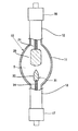
図1は、本発明の放電ランプ用陰極の製造方法により得られる陰極を備える放電ランプの一例における構成を示す説明用断面図である。
この放電ランプは、例えば石英ガラスよりなる発光管10を有する。この発光管10は、内部に放電空間Sを形成する外形が回転楕円体状の発光部11と、この発光部11の両端の各々に一体に連設された、管軸に沿って外方に伸びるロッド状の一方の封止部12および他方の封止部13とにより構成されている。
<Discharge lamp>
Hereinafter, embodiments of the present invention will be described in detail.
FIG. 1 is an explanatory cross-sectional view showing a configuration of an example of a discharge lamp including a cathode obtained by the method for producing a cathode for a discharge lamp of the present invention.
The discharge lamp has an
この発光管10の放電空間S内には、陽極20および陰極30が発光管10の軸方向に沿って互いに対向するよう配置されている。
In the discharge space S of the
発光管10における発光部11内には、例えば、水銀、キセノンガス等の希ガスなどの発光物質が封入されている。
A light emitting material such as a rare gas such as mercury or xenon gas is sealed in the
陽極20および陰極30は、それぞれ支持棒24,34によって保持されている。
The
一方の封止部12の内部には、モリブデンよりなる金属箔(図示省略)が、例えばシュリンクシールにより気密に埋設されている。この金属箔の一端には、支持棒24の基端が溶接されて電気的に接続されている。また、金属箔の他端には、一方の封止部12の外端から外方に突出する外部リード(図示省略)が溶接されて電気的に接続されている。
Inside one sealing
他方の封止部13の内部には、モリブデンよりなる金属箔(図示省略)が、例えばシュリンクシールにより気密に埋設されている。この金属箔の一端には、支持棒34の基端が溶接されて電気的に接続されている。また、金属箔の他端には、他方の封止部13の外端から外方に突出する外部リード(図示省略)が溶接されて電気的に接続されている。
Inside the other sealing
この例の放電ランプには、一方の封止部12および他方の封止部13の各々の端部に、口金16,17が設けられている。これらの口金16,17は、それぞれ外部リードに電気的に接続されている。
In the discharge lamp of this example,
なお、本発明に係る放電ランプは、垂直点灯する場合もあれば水平点灯する場合もある。 The discharge lamp according to the present invention may be lit vertically or horizontally.
<陰極:第1の実施形態>
図2は、本発明の放電ランプ用陰極の製造方法により得られる陰極の一例における構成を示す説明用断面図である。
この陰極30は、タングステンからなる本体部31と、この本体部31の先端面に接合された、エミッタ物質を含む先端部32とが接合されてなるものである。
<Cathode: First Embodiment>
FIG. 2 is a cross-sectional view illustrating the structure of an example of a cathode obtained by the method for manufacturing a cathode for a discharge lamp of the present invention.
The
この例の本体部31は、円柱状の胴部分31aと、この胴部31aに連続して形成された、先端に向かって小径となる円錐台状の先端部分31bとを有している。
この例の本体部31は、例えば純度99.99質量%の純タングステンからなる。
The
The
この例の先端部32は、陰極先端に向かって小径となる円錐台状に形成されている。先端部32の先端面は平坦面とされている。
The
この例の先端部32は、例えば酸化トリウム(ThO2 )がドープされたタングステン(トリエーテッドタングステン)からなる。先端部32は、主成分であるタングステンに、エミッタ物質としてのトリウムを酸化トリウム(ThO2 )またはトリウム(Th)の状態で担持している。
先端部32におけるエミッタ物質の濃度は、0.1〜5.0質量%であることが好ましく、より好ましくは0.3〜2.5質量%である。
先端部32に含有されるエミッタ物質としては、酸化トリウム以外のものでもよく、例えば、酸化ランタン、酸化セリウムなどの希土類酸化物などであってもよい。
The
The concentration of the emitter substance at the
The emitter material contained in the
陰極30においては、先端部32に含有されているエミッタ物質が、ランプ点灯中に高温となることによって還元され、トリウム原子となって、タングステン粒の粒界拡散や表面拡散によって温度が高い先端面へ移動し、供給される。これによって、陰極先端面の仕事関数を低下させ、電子放出特性が良好なものとなる。
In the
<放電ランプ用陰極の製造方法>
本発明の放電ランプ用陰極の製造方法は、タングステンからなる本体部と、エミッタ物質を含む先端部とが接合されてなる放電ランプ用陰極の製造方法において、本体部形成材および先端部形成材の少なくとも一方の被接合面に突起部を形成する突起部形成工程と、突起部の先端と本体部形成材または先端部形成材の被接合面とを対向させて当接させた状態で、本体部形成材と先端部形成材とを通電させることにより、突起部を溶融させ、当該本体部形成材および当該先端部形成材を溶着して接合体を形成する接合工程とを有し、接合工程の後、接合体を、突起部による溶着部分の少なくとも一部が残存するように切削することにより、円錐台形状の先端部を形成する切削工程を有することが好ましい。
以下、図2に示す陰極の製造方法の一例について具体的に説明する。
<Method for producing cathode for discharge lamp>
The method for producing a cathode for a discharge lamp of the present invention is a method for producing a cathode for a discharge lamp in which a body portion made of tungsten and a tip portion containing an emitter substance are joined. A main body portion in a state in which a protrusion forming step for forming a protrusion on at least one surface to be joined and the tip of the protrusion and the body portion forming material or the surface to be joined of the tip portion forming material are opposed to each other A bonding step of melting the protrusion by welding the forming material and the tip portion forming material, and welding the main body portion forming material and the tip portion forming material to form a joined body. After that, it is preferable to have a cutting step of forming the truncated cone-shaped tip by cutting the joined body so that at least a part of the welded portion by the protrusion remains.
Hereinafter, an example of the manufacturing method of the cathode shown in FIG. 2 will be specifically described.
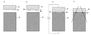
(1)突起部形成工程
図3(a)に示すように、本体部形成材41と先端部形成材42とを用意する。この本体部形成材41は、製造すべき陰極30の本体部31における胴部分31aの径と同等の径を有する円柱状の形状を有する。また、先端部形成材42は、本体部形成材41の径と同等の径を有する円柱状の形状を有する。
次に、図3(b)に示すように、先端部形成材42の被接合面42sに突起部43を形成する。
突起部43の形成方法としては、例えば旋盤などで切削する方法が挙げられる。
(1) Protrusion part formation process As shown to Fig.3 (a), the main-body
Next, as shown in FIG. 3B, the
Examples of the method of forming the
この例の突起部43は、先端部形成材42の被接合面42sの中央領域を取り囲むように円環状に形成されており、突起部43の端面43sは平坦面とされている。
この例の突起部43の陰極30の軸方向に沿った断面形状は、長方形状である。
The
The cross-sectional shape along the axial direction of the
本発明においては、突起部43は、後述する切削工程において切削される領域部分(以下、「被切削部分」ともいう。)より陰極の中心軸側に形成されることが必須である。
突起部43の高さは、0.1〜1.0mmであることが好ましく、突起部43の端面43sの幅は、1〜3mm程度であることが好ましい。突起部43は、先端部形成材42の被接合面42sの中央領域を取り囲むように円環状に複数形成することもできる。
また、突起部43の端面43sの面積(Sw)は、後述する実験例からも示されるように、接合強度の観点から、本体部形成材41または先端部形成材42の被接合面の面積(S)の0.3倍以上であることが好ましく、より好ましくは0.5倍以上0.8倍以下である。
In the present invention, it is essential that the
The height of the
Further, the area (Sw) of the
(2)接合工程
図3(c)に示すように、先端部形成材42に形成された突起部43の端面43sと本体部形成材41の被接合面41sとを、先端部形成材42の中心軸と本体部形成材41の中心軸とが一致した状態で対向させて当接させる。この状態を維持したまま、本体部形成材41と先端部形成材42とを接合方向に加圧した状態で通電させることにより、突起部43を加熱溶融させ、本体部形成材41および先端部形成材42を溶着して接合体45を形成する。このとき、本体部形成材41および先端部形成材42を通電加熱することにより、熱容量の大きい母体の材料よりも先に、熱容量の小さい突起部43のみが溶融することとなる。このように、突起部43のみが溶融することにより、突起部43と、対向する本体部形成材41の被接合面41sとが接着し、本体部形成材41と先端部形成材42とが溶着され、接合体45が形成される。
ここで、形成された接合体45においては、本体部形成材41の被接合面41sと先端部形成材42の被接合面42sとの界面(以下、「接合面」ともいう。)において、溶融された突起部43によって溶着された部分(以下、「溶着部分」ともいう。)43X以外の領域は、溶着されていない。
(2) Joining Step As shown in FIG. 3C, the
Here, in the formed bonded
通電条件としては、各形成材の寸法や突起部の寸法によって異なるが、電流量が例えば5,000〜10,000A、通電時間が例えば5〜20秒間である。 The energization conditions vary depending on the dimensions of the respective forming materials and the dimensions of the protrusions, but the amount of current is, for example, 5,000 to 10,000 A, and the energization time is, for example, 5 to 20 seconds.
以上のような接合工程によれば、従来の拡散接合に比べて、短時間での接合が可能となり製造時間を短縮することができる。ここで、従来の拡散接合においては、各形成材の被接合面において、溶融点以下の温度で溶融させず接合させるため、1回の接合時間がおよそ15〜20分間程度である。
また、完全な平面同士で接合する方法ではないが、接合面の周方向に均一な溶着部分43Xを形成することにより、接合面での接合に準じた接合強度を得ることができる。
さらに、接合面において、溶着されていない領域があることにより、先端部の熱が本体部に伝導し難く、先端部の温度が高温に維持されるので、エミッタ効率が維持される。
According to the joining process as described above, joining in a short time is possible and manufacturing time can be shortened as compared with conventional diffusion joining. Here, in the conventional diffusion bonding, since the bonding surfaces of the respective forming materials are bonded without being melted at a temperature equal to or lower than the melting point, one bonding time is approximately 15 to 20 minutes.
Moreover, although it is not the method of joining by perfect planes, the joint strength according to the joining in a joining surface can be obtained by forming the
Furthermore, since there is a region that is not welded on the joint surface, the heat at the tip is hardly conducted to the main body, and the temperature at the tip is maintained at a high temperature, so that the emitter efficiency is maintained.
(3)切削工程
図3(d)に示すように、接合工程により形成された接合体45を、溶着部分43Xの少なくとも一部が残存するように例えば旋盤などで切削することにより、円錐台形状の先端部32を形成する(図3(d)の破線部分参照)。
切削工程においては、溶着部分43Xの全てが除去されないように切削することが必須であるが、得られる陰極の機械的強度の観点から、溶着部分43Xよりも外側の部分を切削することが好ましい。すなわち、被切削部分が溶着部分43Xと一部重なっていてもよいが、被切削部分が溶着部分43Xよりも外側であることが好ましい。
(3) Cutting step As shown in FIG. 3 (d), the joined
In the cutting process, it is essential to perform cutting so that not all of the welded
なお、図3(d)の例では、本体部形成材41の一部についても切削されているが、先端部形成材42のみを切削してもよい。
In addition, in the example of FIG.3 (d), although part of the main-body-
<陰極:第2の実施形態>
図4は、本発明の放電ランプ用陰極の製造方法により得られる陰極の他の例における構成を示す説明用断面図である。
この陰極30Aは、タングステンからなる本体部31と、この本体部31の先端面に接合された、エミッタ物質を含む先端部32とが接合されてなるものである。
本体部31には、円柱状の形状を有するエミッタ部材Eが収容されたエミッタ収容部44が設けられている。
<Cathode: Second Embodiment>
FIG. 4 is an explanatory cross-sectional view showing the configuration of another example of the cathode obtained by the method for manufacturing a cathode for a discharge lamp of the present invention.
The
The
エミッタ部材Eは、その先端面(図4における上面)が先端部32の底面に密着している。
エミッタ部材Eは、エミッタ物質が含有されてなるものであり、具体的には、高融点金属材料およびエミッタ物質の焼結体により構成されている。
エミッタ部材Eを構成する高融点金属材料としては、タングステン、モリブデンなどを用いることができる。
エミッタ部材Eにおけるエミッタ物質の濃度は、10〜80質量%であることが好ましく、より好ましくは20〜50質量%である。
The emitter member E has a distal end surface (upper surface in FIG. 4) in close contact with the bottom surface of the
The emitter member E contains an emitter material, and is specifically composed of a refractory metal material and a sintered body of the emitter material.
As the refractory metal material constituting the emitter member E, tungsten, molybdenum or the like can be used.
The concentration of the emitter substance in the emitter member E is preferably 10 to 80% by mass, more preferably 20 to 50% by mass.
図4に示す陰極においては、本体部31にエミッタ収容部44が設けられていることの他は、図2に示す陰極の構成と同様であるので、その他の構成の説明は省略する。
The cathode shown in FIG. 4 is the same as the cathode shown in FIG. 2 except that the
<放電ランプ用陰極の製造方法>
以下、図4に示す陰極の製造方法の一例について具体的に説明する。
<Method for producing cathode for discharge lamp>
Hereinafter, an example of the manufacturing method of the cathode shown in FIG. 4 is demonstrated concretely.
(1)突起部形成工程
図5(a)に示すように、本体部形成材41と先端部形成材42とを用意する。この本体部形成材41は、製造すべき陰極30Aの本体部31における胴部分31aの径と同等の径を有する円柱状の形状を有し、当該本体部形成材41の中心部に中心軸に沿って円柱状の空間を有するエミッタ収容部44が形成されている。また、先端部形成材42は、本体部形成材41の径と同等の径を有する円柱状の形状を有する。そして、本体部形成材41の被接合面41sに露出するようにエミッタ部材Eをエミッタ収容部44に配置する。
次に、図5(b)に示すように、先端部形成材42の被接合面42sに突起部43を切削などにより形成する。
(1) Protrusion part formation process As shown to Fig.5 (a), the main-body
Next, as shown in FIG. 5B, the
この例の突起部43は、エミッタ収容部44の開口を取り囲む位置に円環状に形成されており、突起部43の端面43sは平坦面とされている。
この例の突起部43の陰極30Aの軸方向に沿った断面形状は、長方形状である。
The
The cross-sectional shape along the axial direction of the
本発明においては、この実施形態のように、本体部形成材および先端部形成材の少なくとも一方に、エミッタ収容部を形成する場合において、突起部は、環状に形成されていることが好ましく、特に、突起部がエミッタ収容部の開口を取り囲む位置に環状に形成されていることが好ましい。これは、接合工程において、エミッタ部材の露出面を確保しながら、その外周を溶着することが好ましいためである。これにより、エミッタ部材が先端部の底面に接触すると共に、その外周の溶着部によって密閉されるので、エミッタ部材からのエミッタ物質を先端部に確実に供給すると共に、エミッタ物質が漏出することを抑制することができる。 In the present invention, as in this embodiment, in the case where the emitter accommodating portion is formed in at least one of the main body portion forming material and the tip portion forming material, the protrusion is preferably formed in an annular shape, The protrusion is preferably formed in an annular shape at a position surrounding the opening of the emitter accommodating portion. This is because it is preferable to weld the outer periphery of the emitter member while securing the exposed surface of the emitter member in the joining step. As a result, the emitter member comes into contact with the bottom surface of the tip portion and is sealed by the welded portion on the outer periphery thereof, so that the emitter material from the emitter member is reliably supplied to the tip portion and the emitter material is prevented from leaking. can do.
(2)接合工程
図5(c)に示すように、先端部形成材42に形成された突起部43の端面43sと本体部形成材41の被接合面41sとを、先端部形成材42の中心軸と本体部形成材41の中心軸とが一致した状態で対向させて当接させる。この状態を維持したまま、本体部形成材41と先端部形成材42とを接合方向に加圧した状態で通電させることにより、突起部43を加熱溶融させ、本体部形成材41および先端部形成材42を溶着して接合体45を形成する。
(2) Joining Step As shown in FIG. 5C, the
(3)切削工程
図5(d)に示すように、接合工程により形成された接合体45を、溶着部分43Xの少なくとも一部が残存するように例えば旋盤などで切削することにより、円錐台形状の先端部32を形成する(図5(d)の破線部分参照)。
(3) Cutting Step As shown in FIG. 5 (d), the joined
以上のように、本発明の放電ランプ用陰極の製造方法においては、本体部形成材と先端部形成材とを通電加熱することによって突起部が溶融され、これにより、本体部形成材と先端部形成材とが溶着して接合するので、従来の拡散接合に比べて、簡便で、短時間での接合が可能となり製造時間を短縮することができる。 As described above, in the method for manufacturing a cathode for a discharge lamp according to the present invention, the protrusion is melted by energizing and heating the main body portion forming material and the tip portion forming material, thereby the main body portion forming material and the tip portion. Since the forming material is welded and bonded, it is simpler and can be bonded in a shorter time than the conventional diffusion bonding, and the manufacturing time can be shortened.
本発明においては、上記の実施の形態に限定されず、種々の変更を加えることが可能である。
例えば、エミッタ収容部は、本体部形成材および先端部形成材の少なくとも一方に形成されればよく、図6に示す陰極30Bのように、先端部32を形成するための先端部形成材にエミッタ収容部44が形成されていてもよい。
また例えば、突起部は、本体部形成材および先端部形成材の少なくとも一方に形成されればよく、突起部が、本体部形成材および先端部形成材の双方に形成される場合には、双方の突起部の端面(先端)同士が対向するように形成されることが好ましい。
さらに例えば、突起部は、環状に形成されていることに限定されず、例えば円盤状に形成されていてもよい。突起部が環状に形成されている場合でも、部分的に間隙がある状態でもよい。また、突起部の陰極の軸方向に沿った断面形状としては、例えば、台形状、矩形状などが挙げられるが、突起部の端面は、平坦面であることに限定されず、曲面であってもよい。
The present invention is not limited to the above embodiment, and various modifications can be made.
For example, the emitter accommodating portion may be formed on at least one of the main body portion forming material and the tip portion forming material, and the emitter is formed on the tip portion forming material for forming the
In addition, for example, the protrusion may be formed on at least one of the body part forming material and the tip part forming material, and when the protrusion part is formed on both the body part forming material and the tip part forming material, both It is preferable that end surfaces (tips) of the protrusions are formed so as to face each other.
Furthermore, for example, the protrusion is not limited to being formed in an annular shape, and may be formed in a disk shape, for example. Even in the case where the protrusion is formed in an annular shape, there may be a state where there is a gap partially. In addition, examples of the cross-sectional shape of the protrusion along the axial direction of the cathode include a trapezoidal shape and a rectangular shape, but the end surface of the protrusion is not limited to a flat surface, and is a curved surface. Also good.
〔実験例〕
各形成材の接合において、拡散接合によって得られた接合体と、本発明に係る突起部を溶着すること(以下、「突起溶着」ともいう。)によって得られた接合体との接合強度を測定した。
具体的には、純タングステンからなる外径φ15mm、全長80mmのタングステン棒(本体部)と、ThO2 をドープしたタングステン(ThO2 の濃度:2質量%)からなる外径φ15mm、全長80mmのトリエーテッドタングステン棒(先端部)との接合を、拡散接合と突起溶着とで行い、得られた接合体の引張強度をそれぞれ測定した。なお、突起溶着については、先端部の被接合面に高さ1mmの突起部を円環状に形成した。また、突起部の端面の面積を「Sw(mm2 )」とし、先端部の被接合面の面積を「S(mm2 )」としたとき、突起部の端面の面積Swが、0.2×S、0.3×S、0.5×SおよびSである場合について行った。
[Experimental example]
In the bonding of each forming material, the bonding strength between the bonded body obtained by diffusion bonding and the bonded body obtained by welding the protrusions according to the present invention (hereinafter also referred to as “protrusion welding”) is measured. did.
Specifically, outer diameter 15 mm made of pure tungsten, tungsten rod total length 80mm (body portion), (concentration of ThO 2: 2 wt%) ThO 2 doped tungsten consisting outer diameter 15 mm, the total length 80mm Torie Bonding with the Ted tungsten rod (tip portion) was performed by diffusion bonding and projection welding, and the tensile strength of the obtained bonded body was measured. In addition, about protrusion welding, the 1 mm high protrusion part was formed in the annular | circular shape in the to-be-joined surface of the front-end | tip part. In addition, when the area of the end surface of the protrusion is “Sw (mm 2 )” and the area of the surface to be bonded is “S (mm 2 )”, the area Sw of the end surface of the protrusion is 0.2. It was performed for the cases of xS, 0.3xS, 0.5xS and S.

表1の結果より、本発明に係る突起溶着においては、突起部の端面の面積Swが0.3×S以上である場合に、拡散接合を上回る接合強度が得られることが確認された。 From the results in Table 1, it was confirmed that in the projection welding according to the present invention, when the area Sw of the end face of the projection is 0.3 × S or more, a bonding strength exceeding the diffusion bonding can be obtained.
〈実施例1〉
以下に示す工程を経て、陰極〔1〕を作製した。
(1)突起部形成工程
下記寸法となるように、各形成材を切削処理し、表面を研磨・洗浄処理し、水素処理を1000℃で行った。なお、突起部は先端部形成材に形成した。
本体部形成材(41)の寸法:外径10mm、全長18mm
本体部形成材(41)の材質:純タングステン
先端部形成材(42)の寸法:外径10mm、全長10mm
先端部形成材(42)の材質:ThO2 をドープしたタングステン(ThO2 の濃度:2質量%)
突起部(43)の寸法:外径7mm、幅2.4mm、高さ1mm(突起部の端面の面積が先端部形成材の被接合面の面積の0.3倍)
(2)接合工程
突起部(43)の端面(43s)と先端部形成材(42)の被接合面(42s)とを対向させて当接させ、本体部形成材と先端部形成材とを加圧条件:5kNで加圧し、通電条件:電流10,000A、10秒間で通電させた。
(3)切削工程
接合工程により形成された接合体を、下記の寸法となるように切削した後、洗浄を行い、真空熱処理を行い、7kWのキセノンランプの陰極〔1〕を作製した。
陰極(30)の寸法:外径10mm、全長21mm、先端角40度
<Example 1>
A cathode [1] was produced through the following steps.
(1) Protrusion part formation process Each formation material was cut and the surface was polished and washed so as to have the following dimensions, and hydrogen treatment was performed at 1000 ° C. The protrusions were formed on the tip forming material.
Dimensions of main body forming material (41):
Body part forming material (41) material: Pure tungsten tip forming material (42) dimensions: 10 mm outer diameter, 10 mm overall length
The material of the tip forming material (42): ThO 2 doped tungsten (concentration of ThO 2: 2 mass%)
Dimensions of protrusion (43): outer diameter 7 mm, width 2.4 mm, height 1 mm (the area of the end face of the protrusion is 0.3 times the area of the joined surface of the tip forming material)
(2) Joining process The end face (43s) of the projection (43) and the face to be joined (42s) of the tip forming member (42) are brought into contact with each other to bring the main body forming member and the tip forming member into contact. Pressurizing condition: pressurized at 5 kN, energizing condition: current 10,000 A, energized for 10 seconds.
(3) Cutting process After the joined body formed by the joining process was cut to the following dimensions, it was washed and subjected to vacuum heat treatment to produce a cathode [1] of a 7 kW xenon lamp.
Dimensions of cathode (30):
〈実施例2〉
以下に示す工程を経て、陰極〔2〕を作製した。
(1)突起部形成工程
下記寸法となるように、各形成材を切削処理し、表面を研磨・洗浄処理し、水素処理を1000℃で行った。なお、突起部は先端部形成材に形成し、本体部形成材にエミッタ収容部を形成した。
本体部形成材(41)の寸法:外径8mm、全長41.5mm
本体部形成材(41)の材質:純タングステン
先端部形成材(42)の寸法:外径8mm、全長10mm
先端部形成材(42)の材質:CeO2 をドープしたタングステン(CeO2 の濃度:2質量%)
突起部(43)の寸法:外径5.6mm、幅1.1mm、高さ1mm(突起部の端面の面積が先端部形成材の被接合面の面積の0.3倍)
エミッタ収容部(44)の寸法:孔径2.5mm、全長3mm
エミッタ部材(E)の材料:CeO2 ,ZrO2 ,Wの焼結体
(2)接合工程
エミッタ収容部(44)にエミッタ部材(E)を挿入し、突起部(43)の端面(43s)と先端部形成材(42)の被接合面(42s)とを対向させて当接させ、本体部形成材と先端部形成材とを加圧条件:3kNで加圧し、通電条件:電流6,000A、10秒間で通電させた。
(3)切削工程
接合工程により形成された接合体を、下記の寸法となるように切削した後、洗浄を行い、真空熱処理を行い、2kWの高圧UVランプの陰極〔2〕を作製した。
陰極(30)の寸法:外径8mm、全長50mm、先端角40度
<Example 2>
The cathode [2] was produced through the following steps.
(1) Protrusion part formation process Each formation material was cut and the surface was polished and washed so as to have the following dimensions, and hydrogen treatment was performed at 1000 ° C. The protrusion was formed on the tip portion forming material, and the emitter accommodating portion was formed on the main body forming material.
Dimensions of main body forming material (41): outer diameter 8mm, total length 41.5mm
Material of main body forming material (41): Pure tungsten tip forming material (42) dimensions: outer diameter 8 mm,
Tip part forming material (42): CeO 2 doped tungsten (CeO 2 concentration: 2 mass%)
Dimensions of protrusion (43): outer diameter 5.6 mm, width 1.1 mm, height 1 mm (the area of the end face of the protrusion is 0.3 times the area of the joined surface of the tip forming material)
Dimensions of emitter housing (44): hole diameter 2.5mm, total length 3mm
Material of emitter member (E): CeO 2 , ZrO 2 , W sintered body (2) joining step The emitter member (E) is inserted into the emitter housing portion (44), and the end surface (43s) of the projection (43) And the to-be-joined surface (42s) of the tip portion forming material (42) are brought into contact with each other, the body portion forming material and the tip portion forming material are pressurized at a pressure condition of 3 kN, and an energizing condition is a current 6, 000 A was energized for 10 seconds.
(3) Cutting process After the joined body formed by the joining process was cut to the following dimensions, it was washed and subjected to vacuum heat treatment to produce a cathode [2] of a 2 kW high-pressure UV lamp.
Dimensions of cathode (30): outer diameter 8 mm, total length 50 mm, tip angle 40 degrees
〈比較例1〉
実施例1において、突起部形成工程において突起部を形成せず、接合工程において、真空処理、加熱処理(1800℃、7分間)および冷却処理により拡散接合を行ったことの他は同様にして比較用陰極〔1〕を作製した。
<Comparative example 1>
In Example 1, the protrusions were not formed in the protrusion formation process, and the comparison was made in the same manner except that diffusion bonding was performed by vacuum treatment, heat treatment (1800 ° C., 7 minutes) and cooling treatment in the joining step. A cathode [1] was prepared.
得られた陰極〔1〕,〔2〕および比較用陰極〔1〕の引張強度を測定したところ、同程度の接合強度であった。
以上の結果から明らかなように、実施例1および2に係る陰極〔1〕,〔2〕によれば、拡散接合に比べ短時間で接合することができ、得られる陰極が、拡散接合による接合の場合と同等の機械的強度を有していることが確認された。
When the tensile strengths of the obtained cathodes [1] and [2] and comparative cathode [1] were measured, the joint strength was comparable.
As is clear from the above results, according to the cathodes [1] and [2] according to Examples 1 and 2, the cathode can be bonded in a shorter time than diffusion bonding, and the obtained cathode is bonded by diffusion bonding. It was confirmed that it had the same mechanical strength as in the case of.
10 発光管
11 発光部
12 一方の封止部
13 他方の封止部
16,17 口金
20 陽極
24 支持棒
30,30A,30B 陰極
31 本体部
31a 胴部分
31b 先端部分
32 先端部
34 支持棒
41 本体部形成材
41s 被接合面
42 先端部形成材
42s 被接合面
43 突起部
43s 端面
43X 溶着部分
44 エミッタ収容部
45 接合体
E エミッタ部材
S 放電空間
DESCRIPTION OF
Claims (4)
タングステンからなる本体部形成材およびエミッタ物質がドープされたタングステンからなる先端部形成材の少なくとも一方の被接合面に突起部を形成する突起部形成工程と、
前記突起部の先端と前記本体部形成材または前記先端部形成材の被接合面とを対向させて当接させた状態で、前記本体部形成材と前記先端部形成材とを通電させることにより、前記突起部を溶融させ、当該本体部形成材および当該先端部形成材を溶着して接合体を形成する接合工程とを有することを特徴とする放電ランプ用陰極の製造方法。 In a method for manufacturing a cathode for a discharge lamp in which a main body portion made of tungsten and a tip portion made of tungsten doped with an emitter material are joined,
A projecting portion forming step of forming a projecting portion on at least one bonded surface of a body portion forming material made of tungsten and a tip portion forming material made of tungsten doped with an emitter substance ;
By energizing the body part forming material and the tip part forming material in a state where the tip of the projection and the body part forming material or the surface to be joined of the tip part forming material are opposed to each other A method for producing a cathode for a discharge lamp, comprising: joining a step of melting the protrusion and welding the body portion forming material and the tip portion forming material to form a joined body.
前記突起部がエミッタ収容部の開口を取り囲む位置に形成されていることを特徴とする請求項3に記載の放電ランプ用陰極の製造方法。
At least one of the main body part forming material and the tip part forming material is formed with an emitter housing part in which an emitter member exposed to the surface to be joined is housed,
4. The method for manufacturing a cathode for a discharge lamp according to claim 3, wherein the protrusion is formed at a position surrounding the opening of the emitter accommodating portion.
Priority Applications (4)
| Application Number | Priority Date | Filing Date | Title |
|---|---|---|---|
| JP2013265193A JP5949747B2 (en) | 2013-12-24 | 2013-12-24 | Method for producing cathode for discharge lamp and discharge lamp |
| CN201480037590.3A CN105359252B (en) | 2013-10-02 | 2014-09-18 | The manufacture method of the negative electrode of short arc discharge lamp and short arc discharge lamp |
| PCT/JP2014/074663 WO2015049995A1 (en) | 2013-10-02 | 2014-09-18 | Short-arc discharge lamp and short-arc discharge lamp cathode production method |
| TW103133996A TWI609407B (en) | 2013-10-02 | 2014-09-30 | Method for producing cathodes for short arc discharge lamps and short arc discharge lamps |
Applications Claiming Priority (1)
| Application Number | Priority Date | Filing Date | Title |
|---|---|---|---|
| JP2013265193A JP5949747B2 (en) | 2013-12-24 | 2013-12-24 | Method for producing cathode for discharge lamp and discharge lamp |
Publications (2)
| Publication Number | Publication Date |
|---|---|
| JP2015122195A JP2015122195A (en) | 2015-07-02 |
| JP5949747B2 true JP5949747B2 (en) | 2016-07-13 |
Family
ID=53533659
Family Applications (1)
| Application Number | Title | Priority Date | Filing Date |
|---|---|---|---|
| JP2013265193A Expired - Fee Related JP5949747B2 (en) | 2013-10-02 | 2013-12-24 | Method for producing cathode for discharge lamp and discharge lamp |
Country Status (1)
| Country | Link |
|---|---|
| JP (1) | JP5949747B2 (en) |
Families Citing this family (1)
| Publication number | Priority date | Publication date | Assignee | Title |
|---|---|---|---|---|
| JP6265456B1 (en) * | 2017-06-29 | 2018-01-24 | ジャパンモード株式会社 | Virtual currency trading system, virtual currency trading apparatus, and virtual currency trading program |
Family Cites Families (6)
| Publication number | Priority date | Publication date | Assignee | Title |
|---|---|---|---|---|
| JP3175592B2 (en) * | 1996-05-17 | 2001-06-11 | ウシオ電機株式会社 | Discharge lamp electrode |
| JP2002008816A (en) * | 2000-06-20 | 2002-01-11 | Toyota Motor Corp | Joining method of conductor piece for electrical connection and reinforcing piece for conductor piece junction |
| JP2002081874A (en) * | 2000-09-11 | 2002-03-22 | Canon Inc | Plate type heat pipe and its manufacturing method |
| JP4596855B2 (en) * | 2004-08-25 | 2010-12-15 | 京セラ株式会社 | Metal-ceramic composite structure and electrode member for plasma generation comprising the same |
| JP5556315B2 (en) * | 2010-04-02 | 2014-07-23 | ウシオ電機株式会社 | Short arc type discharge lamp |
| JP5024466B1 (en) * | 2011-03-10 | 2012-09-12 | ウシオ電機株式会社 | Short arc type discharge lamp |
-
2013
- 2013-12-24 JP JP2013265193A patent/JP5949747B2/en not_active Expired - Fee Related
Also Published As
| Publication number | Publication date |
|---|---|
| JP2015122195A (en) | 2015-07-02 |
Similar Documents
| Publication | Publication Date | Title |
|---|---|---|
| US8018155B2 (en) | Short arc type high voltage electrical discharge electrode, short arc type high voltage electrical discharge tube, short arc type high voltage electrical discharge light source apparatus, and their manufacturing methods | |
| US20090121634A1 (en) | Electrode for a Discharge Lamp and a Method for Producing Such an Electrode | |
| US6135840A (en) | Discharge lamp of the short arc type and process for production thereof | |
| JP4681668B2 (en) | Foil seal lamp | |
| TW201415527A (en) | Method for manufacturing discharge lamp electrode | |
| JP5949747B2 (en) | Method for producing cathode for discharge lamp and discharge lamp | |
| JP6633826B2 (en) | Discharge lamp | |
| JP5346428B2 (en) | Super high pressure mercury lamp | |
| JP2000285849A (en) | Electrode for electric discharge lamp, manufacture thereof and electric discharge lamp using it | |
| KR102469050B1 (en) | Discharge lamp | |
| KR20090079790A (en) | Flash lamp and method of manufacturing the same | |
| CN101924009B (en) | High-pressure discharge lamp | |
| JP6593777B2 (en) | Short arc type discharge lamp | |
| TWI609407B (en) | Method for producing cathodes for short arc discharge lamps and short arc discharge lamps | |
| KR102460981B1 (en) | Discharge lamp, electrode for discharge lamp, method for producing discharge lamp, and method for producing electrode for discharge lamp | |
| JP5668796B2 (en) | Cathode and discharge lamp for discharge lamp | |
| JP2008059764A (en) | Discharge lamp, and its forming method | |
| JP5825316B2 (en) | Short arc type discharge lamp | |
| JP5056916B2 (en) | High pressure discharge lamp | |
| JP6562298B2 (en) | Discharge lamp | |
| JP3290649B2 (en) | Discharge lamp and lamp unit | |
| JP2000003695A (en) | Discharge lamp | |
| JP4973509B2 (en) | Short arc type high pressure discharge lamp | |
| JP2732454B2 (en) | High pressure mercury lamp | |
| JP2010021066A (en) | Mount for thermionic cathode fluorescent lamp, and thermionic cathode fluorescent lamp |
Legal Events
| Date | Code | Title | Description |
|---|---|---|---|
| A131 | Notification of reasons for refusal |
Free format text: JAPANESE INTERMEDIATE CODE: A131 Effective date: 20150915 |
|
| A521 | Request for written amendment filed |
Free format text: JAPANESE INTERMEDIATE CODE: A523 Effective date: 20151111 |
|
| TRDD | Decision of grant or rejection written | ||
| A01 | Written decision to grant a patent or to grant a registration (utility model) |
Free format text: JAPANESE INTERMEDIATE CODE: A01 Effective date: 20160510 |
|
| A61 | First payment of annual fees (during grant procedure) |
Free format text: JAPANESE INTERMEDIATE CODE: A61 Effective date: 20160523 |
|
| R150 | Certificate of patent or registration of utility model |
Ref document number: 5949747 Country of ref document: JP Free format text: JAPANESE INTERMEDIATE CODE: R150 |
|
| R250 | Receipt of annual fees |
Free format text: JAPANESE INTERMEDIATE CODE: R250 |
|
| R250 | Receipt of annual fees |
Free format text: JAPANESE INTERMEDIATE CODE: R250 |
|
| R250 | Receipt of annual fees |
Free format text: JAPANESE INTERMEDIATE CODE: R250 |
|
| LAPS | Cancellation because of no payment of annual fees |