JP5944727B2 - Sphygmomanometer and pump drive system - Google Patents
Sphygmomanometer and pump drive system Download PDFInfo
- Publication number
- JP5944727B2 JP5944727B2 JP2012095287A JP2012095287A JP5944727B2 JP 5944727 B2 JP5944727 B2 JP 5944727B2 JP 2012095287 A JP2012095287 A JP 2012095287A JP 2012095287 A JP2012095287 A JP 2012095287A JP 5944727 B2 JP5944727 B2 JP 5944727B2
- Authority
- JP
- Japan
- Prior art keywords
- voltage
- pump
- switching elements
- control
- series circuit
- Prior art date
- Legal status (The legal status is an assumption and is not a legal conclusion. Google has not performed a legal analysis and makes no representation as to the accuracy of the status listed.)
- Active
Links
- 230000007704 transition Effects 0.000 claims description 33
- 230000036772 blood pressure Effects 0.000 claims description 27
- 238000009530 blood pressure measurement Methods 0.000 claims description 22
- 239000012530 fluid Substances 0.000 claims description 21
- 238000000034 method Methods 0.000 description 13
- 230000009467 reduction Effects 0.000 description 11
- 102100031699 Choline transporter-like protein 1 Human genes 0.000 description 9
- 101000940912 Homo sapiens Choline transporter-like protein 1 Proteins 0.000 description 9
- 238000001514 detection method Methods 0.000 description 7
- 238000005259 measurement Methods 0.000 description 7
- 238000012545 processing Methods 0.000 description 7
- 210000001367 artery Anatomy 0.000 description 6
- 230000008859 change Effects 0.000 description 6
- 230000035488 systolic blood pressure Effects 0.000 description 5
- 239000003990 capacitor Substances 0.000 description 4
- 230000003247 decreasing effect Effects 0.000 description 4
- 230000008569 process Effects 0.000 description 4
- 210000000707 wrist Anatomy 0.000 description 4
- 238000004364 calculation method Methods 0.000 description 3
- 238000009532 heart rate measurement Methods 0.000 description 3
- 230000010355 oscillation Effects 0.000 description 3
- 238000005549 size reduction Methods 0.000 description 3
- 230000005856 abnormality Effects 0.000 description 2
- 230000006837 decompression Effects 0.000 description 2
- 230000000737 periodic effect Effects 0.000 description 2
- 102100035954 Choline transporter-like protein 2 Human genes 0.000 description 1
- 102100039497 Choline transporter-like protein 3 Human genes 0.000 description 1
- 101000948115 Homo sapiens Choline transporter-like protein 2 Proteins 0.000 description 1
- 101000889279 Homo sapiens Choline transporter-like protein 3 Proteins 0.000 description 1
- 238000006243 chemical reaction Methods 0.000 description 1
- 230000000295 complement effect Effects 0.000 description 1
- 230000035487 diastolic blood pressure Effects 0.000 description 1
- 230000000694 effects Effects 0.000 description 1
- 230000005669 field effect Effects 0.000 description 1
- 230000006870 function Effects 0.000 description 1
- 238000012986 modification Methods 0.000 description 1
- 230000004048 modification Effects 0.000 description 1
- 238000012360 testing method Methods 0.000 description 1
- 238000004804 winding Methods 0.000 description 1
Images


Classifications
-
- F—MECHANICAL ENGINEERING; LIGHTING; HEATING; WEAPONS; BLASTING
- F04—POSITIVE - DISPLACEMENT MACHINES FOR LIQUIDS; PUMPS FOR LIQUIDS OR ELASTIC FLUIDS
- F04B—POSITIVE-DISPLACEMENT MACHINES FOR LIQUIDS; PUMPS
- F04B45/00—Pumps or pumping installations having flexible working members and specially adapted for elastic fluids
- F04B45/04—Pumps or pumping installations having flexible working members and specially adapted for elastic fluids having plate-like flexible members, e.g. diaphragms
- F04B45/047—Pumps having electric drive
-
- A—HUMAN NECESSITIES
- A61—MEDICAL OR VETERINARY SCIENCE; HYGIENE
- A61B—DIAGNOSIS; SURGERY; IDENTIFICATION
- A61B5/00—Measuring for diagnostic purposes; Identification of persons
- A61B5/02—Detecting, measuring or recording pulse, heart rate, blood pressure or blood flow; Combined pulse/heart-rate/blood pressure determination; Evaluating a cardiovascular condition not otherwise provided for, e.g. using combinations of techniques provided for in this group with electrocardiography or electroauscultation; Heart catheters for measuring blood pressure
- A61B5/021—Measuring pressure in heart or blood vessels
- A61B5/02141—Details of apparatus construction, e.g. pump units or housings therefor, cuff pressurising systems, arrangements of fluid conduits or circuits
-
- A—HUMAN NECESSITIES
- A61—MEDICAL OR VETERINARY SCIENCE; HYGIENE
- A61B—DIAGNOSIS; SURGERY; IDENTIFICATION
- A61B5/00—Measuring for diagnostic purposes; Identification of persons
- A61B5/02—Detecting, measuring or recording pulse, heart rate, blood pressure or blood flow; Combined pulse/heart-rate/blood pressure determination; Evaluating a cardiovascular condition not otherwise provided for, e.g. using combinations of techniques provided for in this group with electrocardiography or electroauscultation; Heart catheters for measuring blood pressure
- A61B5/021—Measuring pressure in heart or blood vessels
- A61B5/022—Measuring pressure in heart or blood vessels by applying pressure to close blood vessels, e.g. against the skin; Ophthalmodynamometers
- A61B5/02225—Measuring pressure in heart or blood vessels by applying pressure to close blood vessels, e.g. against the skin; Ophthalmodynamometers using the oscillometric method
-
- A—HUMAN NECESSITIES
- A61—MEDICAL OR VETERINARY SCIENCE; HYGIENE
- A61B—DIAGNOSIS; SURGERY; IDENTIFICATION
- A61B5/00—Measuring for diagnostic purposes; Identification of persons
- A61B5/02—Detecting, measuring or recording pulse, heart rate, blood pressure or blood flow; Combined pulse/heart-rate/blood pressure determination; Evaluating a cardiovascular condition not otherwise provided for, e.g. using combinations of techniques provided for in this group with electrocardiography or electroauscultation; Heart catheters for measuring blood pressure
- A61B5/021—Measuring pressure in heart or blood vessels
- A61B5/022—Measuring pressure in heart or blood vessels by applying pressure to close blood vessels, e.g. against the skin; Ophthalmodynamometers
- A61B5/0225—Measuring pressure in heart or blood vessels by applying pressure to close blood vessels, e.g. against the skin; Ophthalmodynamometers the pressure being controlled by electric signals, e.g. derived from Korotkoff sounds
- A61B5/02255—Measuring pressure in heart or blood vessels by applying pressure to close blood vessels, e.g. against the skin; Ophthalmodynamometers the pressure being controlled by electric signals, e.g. derived from Korotkoff sounds the pressure being controlled by plethysmographic signals, e.g. derived from optical sensors
-
- A—HUMAN NECESSITIES
- A61—MEDICAL OR VETERINARY SCIENCE; HYGIENE
- A61B—DIAGNOSIS; SURGERY; IDENTIFICATION
- A61B5/00—Measuring for diagnostic purposes; Identification of persons
- A61B5/02—Detecting, measuring or recording pulse, heart rate, blood pressure or blood flow; Combined pulse/heart-rate/blood pressure determination; Evaluating a cardiovascular condition not otherwise provided for, e.g. using combinations of techniques provided for in this group with electrocardiography or electroauscultation; Heart catheters for measuring blood pressure
- A61B5/024—Detecting, measuring or recording pulse rate or heart rate
Landscapes
- Health & Medical Sciences (AREA)
- Life Sciences & Earth Sciences (AREA)
- Cardiology (AREA)
- Vascular Medicine (AREA)
- Engineering & Computer Science (AREA)
- Pathology (AREA)
- Public Health (AREA)
- Physics & Mathematics (AREA)
- Veterinary Medicine (AREA)
- Biophysics (AREA)
- Physiology (AREA)
- Biomedical Technology (AREA)
- Heart & Thoracic Surgery (AREA)
- Medical Informatics (AREA)
- Molecular Biology (AREA)
- Surgery (AREA)
- Animal Behavior & Ethology (AREA)
- General Health & Medical Sciences (AREA)
- Ophthalmology & Optometry (AREA)
- Mechanical Engineering (AREA)
- General Engineering & Computer Science (AREA)
- Measuring Pulse, Heart Rate, Blood Pressure Or Blood Flow (AREA)
- Reciprocating Pumps (AREA)
Description
この発明は血圧計に関し、より詳しくは、血圧測定用カフへ流体を送るポンプと、ポンプを駆動するためのポンプ駆動回路とを備えた血圧計に関する。 The present invention relates to a sphygmomanometer, and more particularly, to a sphygmomanometer including a pump that sends a fluid to a blood pressure measurement cuff and a pump drive circuit for driving the pump.
また、この発明は、ポンプと、ポンプを駆動するためのポンプ駆動回路とを備えたポンプ駆動システムに関する。 The present invention also relates to a pump drive system including a pump and a pump drive circuit for driving the pump.
最近、例えば特許文献1(特開2000−171320号公報)に記載のように、血圧計の血圧測定用カフ(より正確には、カフに内包された空気袋を指す。以下同様。)へ流体を送るポンプとして圧電ポンプ(圧電素子を利用してダイアフラムを駆動するポンプ)を用いる提案がなされている。 Recently, as described in, for example, Patent Document 1 (Japanese Patent Application Laid-Open No. 2000-171320), a blood pressure is measured into a cuff for blood pressure measurement of a sphygmomanometer (more precisely, an air bag enclosed in the cuff; the same applies hereinafter). A proposal has been made to use a piezoelectric pump (a pump that drives a diaphragm by using a piezoelectric element) as a pump for feeding the pressure.
圧電ポンプを駆動するための公知の駆動回路としては、例えば特許文献2(特開2010−142783号公報)に記載のように、低電圧の電源を昇圧して、圧電素子のための高電圧の駆動電源を発生し、その駆動電源を用いながら、低電圧の駆動波形をアンプで増幅して、上記圧電素子を駆動するための駆動信号を得る方式が知られている。また、特許文献3(特開2009−50051号公報)に記載のように、トランスの一次側で電源電圧をスイッチング動作(圧電素子のための駆動周波数で)し、前記トランスの二次側に接続されている圧電素子に駆動電圧を印加する方式が知られている。 As a known drive circuit for driving the piezoelectric pump, for example, as described in Patent Document 2 (Japanese Patent Laid-Open No. 2010-142833), a low-voltage power source is boosted to increase the high-voltage for the piezoelectric element. There is known a method of generating a driving power source and amplifying a low voltage driving waveform with an amplifier while using the driving power source to obtain a driving signal for driving the piezoelectric element. Further, as described in Patent Document 3 (Japanese Patent Laid-Open No. 2009-50051), the power supply voltage is switched on the primary side of the transformer (at the driving frequency for the piezoelectric element) and connected to the secondary side of the transformer. There is known a method of applying a driving voltage to a piezoelectric element.
ここで、例えば手首式血圧計の血圧測定用カフへ流体を送るポンプとして圧電ポンプを用いる場合、上記圧電ポンプ(の圧電素子)を駆動するための駆動信号として、例えば最大で50Vp−p(ピーク・ツー・ピーク電圧)程度の振幅をもつのが望ましい。これとともに、等速加圧(例えば10mmHg/sec)を行うため、また、圧電ポンプの特性ばらつきに適合するために、振幅を例えば0.1V単位で、また、駆動周波数を100Hz単位でそれぞれ細かく制御するのが望ましい。 Here, for example, when a piezoelectric pump is used as a pump for sending fluid to a blood pressure measurement cuff of a wrist sphygmomanometer, for example, a maximum of 50 Vp-p (peak) is used as a drive signal for driving the piezoelectric pump (piezoelectric element). It is desirable to have an amplitude of about (two-peak voltage). At the same time, in order to perform constant-speed pressurization (for example, 10 mmHg / sec) and adapt to variations in the characteristics of the piezoelectric pump, the amplitude is finely controlled in units of 0.1 V and the drive frequency in units of 100 Hz, respectively. It is desirable to do.
しかしながら、特許文献2(特開2010−142783号公報)に記載の方式では、アンプの電源(高電圧の駆動電源)として所定の高電圧を提供する大型の電源が要求されるし、また、アンプも高コストになる。また、振幅や駆動周波数の細かな制御が困難である。このため、小型化、低コスト化、高性能化を達成することができないという問題がある。 However, the method described in Patent Document 2 (Japanese Patent Application Laid-Open No. 2010-142833) requires a large power supply that provides a predetermined high voltage as an amplifier power supply (high voltage drive power supply). Will also be expensive. In addition, fine control of amplitude and drive frequency is difficult. For this reason, there exists a problem that size reduction, cost reduction, and high performance cannot be achieved.
同様に、特許文献3(特開2009−50051号公報)に記載の方式では、トランスが大型で高コストになる。また、振幅や駆動周波数の細かな制御が困難である。このため、小型化、低コスト化、高性能化を達成することができないという問題がある。 Similarly, in the method described in Patent Document 3 (Japanese Patent Laid-Open No. 2009-50051), the transformer is large and expensive. In addition, fine control of amplitude and drive frequency is difficult. For this reason, there exists a problem that size reduction, cost reduction, and high performance cannot be achieved.
そこで、この発明の課題は、血圧測定用カフへ流体を送るポンプと、ポンプを駆動するためのポンプ駆動回路とを備えた血圧計であって、小型化、低コスト化、高性能化を達成できるものを提供することにある。 Accordingly, an object of the present invention is a sphygmomanometer including a pump that sends a fluid to a cuff for blood pressure measurement and a pump drive circuit for driving the pump, and achieves downsizing, cost reduction, and high performance. It is to provide what can be done.
また、この発明の課題は、ポンプと、ポンプを駆動するためのポンプ駆動回路とを備えたポンプ駆動システムであって、小型化、低コスト化、高性能化を達成できるものを提供することにある。 Another object of the present invention is to provide a pump drive system including a pump and a pump drive circuit for driving the pump, which can achieve downsizing, cost reduction, and high performance. is there.
上記課題を解決するため、この発明の血圧計は、
血圧測定用カフへ流体を送るポンプと、
上記ポンプを駆動するためのポンプ駆動回路と、
血圧測定のために上記ポンプ駆動回路を制御する制御部とを少なくとも備え、
上記ポンプ駆動回路は、
電源からの第1のDC電圧を昇圧して第2のDC電圧として出力する昇圧部と、
上記第2のDC電圧に対応する高電位とこの高電位よりも低い基準電位との間に、直列に接続された2個のスイッチング素子をそれぞれ含む第1、第2の直列回路を有するHブリッジ部とを備え、
上記制御部からのブリッジ制御信号によって、上記第1の直列回路の上記2個のスイッチング素子、上記第2の直列回路の上記2個のスイッチング素子は、それぞれオン、オフ制御され、
上記第1の直列回路の上記2個のスイッチング素子の間の第1の接続点と、上記第2の直列回路の上記2個のスイッチング素子の間の第2の接続点との間に生じる電圧が、上記ポンプを駆動するための駆動電圧として用いられることを特徴とする。
In order to solve the above problems, the sphygmomanometer of the present invention is
A pump that sends fluid to a blood pressure cuff;
A pump drive circuit for driving the pump;
A control unit that controls the pump drive circuit for blood pressure measurement,
The pump drive circuit is
A boosting unit that boosts the first DC voltage from the power supply and outputs the first DC voltage as a second DC voltage;
An H-bridge having first and second series circuits each including two switching elements connected in series between a high potential corresponding to the second DC voltage and a reference potential lower than the high potential With
By the bridge control signal from the control unit, the two switching elements of the first series circuit and the two switching elements of the second series circuit are respectively turned on and off,
A voltage generated between a first connection point between the two switching elements of the first series circuit and a second connection point between the two switching elements of the second series circuit. Is used as a driving voltage for driving the pump.
この発明の血圧計では、昇圧部が、電源からの第1のDC電圧を昇圧して第2のDC電圧として出力する。Hブリッジ部が有する第1、第2の直列回路は、それぞれ上記第2のDC電圧に相当する高電位とこの高電位よりも低い基準電位(例えば、接地電位)との間に接続されている。制御部からのブリッジ制御信号によって、上記第1の直列回路の上記2個のスイッチング素子、上記第2の直列回路の上記2個のスイッチング素子は、それぞれオン、オフ制御される。上記第1の直列回路の上記2個のスイッチング素子の間の第1の接続点と、上記第2の直列回路の上記2個のスイッチング素子の間の第2の接続点との間に生じる電圧が、上記ポンプを駆動するための駆動電圧として用いられる。 In the sphygmomanometer according to the present invention, the booster boosts the first DC voltage from the power source and outputs the boosted voltage as the second DC voltage. The first and second series circuits of the H bridge section are connected between a high potential corresponding to the second DC voltage and a reference potential (for example, ground potential) lower than the high potential. . The two switching elements of the first series circuit and the two switching elements of the second series circuit are on / off controlled by a bridge control signal from the control unit, respectively. A voltage generated between a first connection point between the two switching elements of the first series circuit and a second connection point between the two switching elements of the second series circuit. Is used as a driving voltage for driving the pump.
例えば、上記ポンプが圧電ポンプであり、上記制御部からのブリッジ制御信号によって、上記第1の直列回路の上記2個のスイッチング素子は相補的にオン、オフ制御されるとともに、上記第2の直列回路の上記2個のスイッチング素子は、上記第1の直列回路の上記2個のスイッチング素子のオン、オフ制御とは逆の位相で相補的にオン、オフ制御されるものとする。この場合、例えば50Vp−p(ピーク・ツー・ピーク電圧)程度の振幅をもつ駆動電圧を得るためには、上記昇圧部は上記第2のDC電圧として、上記駆動電圧として要求される振幅の半分の電圧、つまり最大で25Vを出力すれば足りる。したがって、電源が、例えば3Vの乾電池(1.5V×2個)でも構成され得る。また、上記昇圧部が、小型で低コストに構成され得る。さらに、Hブリッジ部自体も、比較的部品点数が少ないことから、小型で低コストに構成され得る。 For example, the pump is a piezoelectric pump, and the two switching elements of the first series circuit are complementarily turned on and off by the bridge control signal from the control unit, and the second series It is assumed that the two switching elements of the circuit are complementarily turned on / off in a phase opposite to the on / off control of the two switching elements of the first series circuit. In this case, for example, in order to obtain a drive voltage having an amplitude of about 50 Vp-p (peak-to-peak voltage), the boosting unit uses the second DC voltage as half of the amplitude required as the drive voltage. It is sufficient to output a voltage of 25V, that is, a maximum of 25V. Therefore, the power source can be configured with, for example, a 3V dry battery (1.5V × 2). Further, the boosting unit can be configured in a small size and at a low cost. Furthermore, since the H bridge portion itself has a relatively small number of parts, it can be configured in a small size and at a low cost.
また、上記第1の直列回路の上記2個のスイッチング素子、上記第2の直列回路の上記2個のスイッチング素子をそれぞれオン、オフ制御するために、上記制御部は、上記ブリッジ制御信号として4つのデジタル信号を出力すれば足り、負荷が小さい。したがって、上記制御部は、特段の新たな部品を設けることなく、例えば血圧計を構成する既存のCPU(Central Processing Unit;中央演算処理装置)によって構成され得る。また、上記ブリッジ制御信号としてそのようなCPUが出力するデジタル信号、例えばPWM(Pulse Width Modulation;パルス幅変調)信号を用いれば、オン、オフの細かな制御が可能になり、例えば100Hz単位で上記ポンプのための駆動周波数の細かな制御ができる。したがって、例えば圧電ポンプの特性ばらつき(特に、共振周波数のばらつき)に容易に適合することができる。 In addition, in order to turn on and off the two switching elements of the first series circuit and the two switching elements of the second series circuit, the control unit uses 4 as the bridge control signal. It is enough to output two digital signals, and the load is small. Therefore, the said control part can be comprised by existing CPU (Central Processing Unit; central processing unit) which comprises a blood pressure meter, for example, without providing a special new component. Further, if a digital signal output by such a CPU, for example, a PWM (Pulse Width Modulation) signal, is used as the bridge control signal, fine control of on and off becomes possible. Fine control of the drive frequency for the pump. Therefore, for example, it is possible to easily adapt to variations in characteristics (particularly, variations in resonance frequency) of the piezoelectric pump.
したがって、この血圧計によれば、小型化、低コスト化、高性能化を達成できる。 Therefore, according to this blood pressure monitor, downsizing, cost reduction, and high performance can be achieved.
なお、この血圧計は、上記血圧測定用カフ内の流体圧を検出する圧力センサと、この圧力センサの出力に基づいて被験者の血圧測定値を得る制御部とを備えるのが望ましい。これにより、被験者の血圧測定値を出力することができる。 The sphygmomanometer preferably includes a pressure sensor that detects the fluid pressure in the blood pressure measurement cuff and a control unit that obtains a blood pressure measurement value of the subject based on the output of the pressure sensor. Thereby, a test subject's blood-pressure measurement value can be output.
一実施形態の血圧計では、上記昇圧部は、上記制御部からの昇圧制御信号に応じて、上記第2のDC電圧を可変して出力する昇圧レギュレータであることを特徴とする。 In the sphygmomanometer according to an embodiment, the boosting unit is a boosting regulator that variably outputs the second DC voltage in accordance with a boosting control signal from the control unit.
この一実施形態の血圧計では、上記昇圧部は、上記制御部からの昇圧制御信号に応じて、上記第2のDC電圧を可変して出力する昇圧レギュレータである。このような昇圧レギュレータとしては、市販の小型で安価なものを採用することができる。したがって、この血圧計によれば、さらに小型化、低コスト化を達成できる。 In the sphygmomanometer according to this embodiment, the boosting unit is a boosting regulator that variably outputs the second DC voltage in accordance with a boosting control signal from the control unit. As such a boost regulator, a commercially available small and inexpensive one can be adopted. Therefore, according to this blood pressure monitor, further miniaturization and cost reduction can be achieved.
一実施形態の血圧計では、
上記制御部からの昇圧制御信号はPWM信号であり、
上記昇圧部としての昇圧レギュレータは、上記PWM信号のパルス幅に応じて、上記第2のDC電圧を可変して出力することを特徴とする。
In one embodiment of the sphygmomanometer,
The boost control signal from the control unit is a PWM signal,
The boosting regulator as the boosting unit variably outputs the second DC voltage according to the pulse width of the PWM signal.
この一実施形態の血圧計では、上記制御部からの昇圧制御信号はPWM(Pulse Width Modulation;パルス幅変調)信号であるから、オン、オフの細かな制御が可能になる。上記昇圧部としての昇圧レギュレータは、上記PWM信号のパルス幅に応じて、上記第2のDC電圧を可変して出力する。例えば上記第2のDC電圧を細かく、0.1V単位で上昇させることができる。したがって、例えば上記ポンプが圧電ポンプである場合、等速加圧(例えば10mmHg/sec)を容易に行うことができる。したがって、この血圧計によれば、さらに高性能化を達成できる。 In the sphygmomanometer according to this embodiment, since the boost control signal from the control unit is a PWM (Pulse Width Modulation) signal, fine control of ON and OFF is possible. The boosting regulator as the boosting unit variably outputs the second DC voltage according to the pulse width of the PWM signal. For example, the second DC voltage can be finely increased in units of 0.1V. Therefore, for example, when the pump is a piezoelectric pump, constant pressure pressurization (for example, 10 mmHg / sec) can be easily performed. Therefore, this blood pressure monitor can achieve higher performance.
一実施形態の血圧計では、
上記ポンプは圧電ポンプであり、
上記制御部からのブリッジ制御信号によって、上記第1の直列回路の上記2個のスイッチング素子は相補的にオン、オフ制御されるとともに、上記第2の直列回路の上記2個のスイッチング素子は、上記第1の直列回路の上記2個のスイッチング素子のオン、オフ制御とは逆の位相で相補的にオン、オフ制御されることを特徴とする。
In one embodiment of the sphygmomanometer,
The pump is a piezoelectric pump,
The two switching elements of the first series circuit are complementarily turned on and off by the bridge control signal from the control unit, and the two switching elements of the second series circuit are The two switching elements of the first series circuit are complementarily turned on / off in the opposite phase to the on / off control.
ここで、「圧電ポンプ」とは、圧電素子とこの圧電素子に連結されたダイアフラムとを備え、上記圧電素子に交流電圧が印加されることにより、上記圧電素子とともに上記ダイアフラムが振動し、このダイアフラムの振動によって流体を送り出すポンプである。 Here, the “piezoelectric pump” includes a piezoelectric element and a diaphragm connected to the piezoelectric element. When an AC voltage is applied to the piezoelectric element, the diaphragm vibrates together with the piezoelectric element. This is a pump that pumps out fluid by the vibrations.
この一実施形態の血圧計では、上記制御部からのブリッジ制御信号によって、上記第1の直列回路の上記2個のスイッチング素子は相補的にオン、オフ制御されるとともに、上記第2の直列回路の上記2個のスイッチング素子は、上記第1の直列回路の上記2個のスイッチング素子のオン、オフ制御とは逆の位相で相補的にオン、オフ制御される。これにより、上記ポンプとしての圧電ポンプに、駆動電圧として交流電圧が印加される。したがって、上記圧電ポンプが動作して、血圧測定用カフへ流体を送ることができる。ここで、例えば50Vp−p(ピーク・ツー・ピーク電圧)程度の振幅をもつ駆動電圧を得るためには、上記昇圧部は上記第2のDC電圧として、上記駆動電圧として要求される振幅の半分の電圧、つまり最大で25Vを出力すれば足りる。したがって、電源が、例えば3Vの乾電池(1.5V×2個)で構成され得る。また、上記昇圧部が、小型で低コストに構成され得る。さらに、Hブリッジ部自体も、比較的部品点数が少ないことから、小型で低コストに構成され得る。 In the sphygmomanometer according to this embodiment, the two switching elements of the first series circuit are complementarily turned on and off by the bridge control signal from the control unit, and the second series circuit The two switching elements of the first series circuit are complementarily turned on / off in a phase opposite to the on / off control of the two switching elements of the first series circuit. Thereby, an alternating voltage is applied as a drive voltage to the piezoelectric pump as the pump. Therefore, the piezoelectric pump operates to send fluid to the blood pressure measurement cuff. Here, in order to obtain a driving voltage having an amplitude of, for example, about 50 Vp-p (peak-to-peak voltage), the boosting unit uses the second DC voltage as the second DC voltage, and is half the amplitude required as the driving voltage. It is sufficient to output a voltage of 25V, that is, a maximum of 25V. Therefore, a power supply can be comprised by the dry battery (1.5Vx2 piece) of 3V, for example. Further, the boosting unit can be configured in a small size and at a low cost. Furthermore, since the H bridge portion itself has a relatively small number of parts, it can be configured in a small size and at a low cost.
また、上記第1、第2の直列回路の上記2個のスイッチング素子をオン、オフ制御するために、上記制御部は、上記ブリッジ制御信号として4つのデジタル信号を出力すれば足り、負荷が小さい。したがって、上記制御部は、特段の新たな部品を設けることなく、例えば血圧計を構成する既存のCPUによって構成され得る。また、上記ブリッジ制御信号としてそのようなCPUが出力するデジタル信号、例えばPWM信号によれば、オン、オフの細かな制御が可能になり、上記ポンプのための駆動周波数の細かな制御ができる。したがって、例えば圧電ポンプの特性ばらつきに容易に適合することができる。 Also, in order to turn on and off the two switching elements of the first and second series circuits, it is sufficient for the control unit to output four digital signals as the bridge control signal, and the load is small. . Therefore, the said control part can be comprised by the existing CPU which comprises a blood pressure meter, for example, without providing a special new component. Further, according to the digital signal output from the CPU as the bridge control signal, for example, a PWM signal, fine control of on and off is possible, and fine control of the driving frequency for the pump is possible. Therefore, for example, it is possible to easily adapt to variations in characteristics of the piezoelectric pump.
したがって、この血圧計によれば、さらに小型化、低コスト化、高性能化を達成できる。 Therefore, according to this blood pressure monitor, further miniaturization, cost reduction, and high performance can be achieved.
一実施形態の血圧計では、上記制御部は、上記第1、第2の直列回路の或るスイッチング素子のオン期間とこのオン期間に続く別のスイッチング素子のオン期間との間に、いずれのスイッチング素子もオフしている休止期間を設定する制御を行うことを特徴とする。 In the sphygmomanometer according to an embodiment, the control unit may select any one between an on period of a certain switching element of the first and second series circuits and an on period of another switching element following the on period. Control is performed to set an idle period in which the switching element is also off.
この一実施形態の血圧計では、上記制御部は、上記第1、第2の直列回路の或るスイッチング素子のオン期間とこのオン期間に続く別のスイッチング素子のオン期間との間に、いずれのスイッチング素子もオフしている休止期間を設定する制御を行う。これにより、上記ポンプとしての圧電ポンプに対する駆動電圧の波形において、プラス電圧印加期間とマイナス電圧印加期間との間に、印加電圧ゼロの期間が生ずる。この結果、駆動電圧の反転時、つまりプラス電圧印加期間の開始時、マイナス電圧印加期間の開始時に、上記ポンプとしての圧電ポンプに対する突入電流が制限される。したがって、駆動電圧の反転時における電力消費が抑制され、省エネルギが実現される。 In the sphygmomanometer according to the embodiment, the control unit may be configured between an on period of one switching element of the first and second series circuits and an on period of another switching element following the on period. Control is performed to set a rest period in which the switching element is also off. Thereby, in the waveform of the driving voltage for the piezoelectric pump as the pump, a period of zero applied voltage occurs between the plus voltage application period and the minus voltage application period. As a result, the inrush current to the piezoelectric pump as the pump is limited when the drive voltage is inverted, that is, at the start of the plus voltage application period and at the start of the minus voltage application period. Therefore, power consumption during inversion of the drive voltage is suppressed, and energy saving is realized.
一実施形態の血圧計では、上記制御部は、上記第1、第2の直列回路の各スイッチング素子を、オフ状態からオン状態へ、またオン状態からオフ状態へ、それぞれ有限の遷移期間をかけて遷移させる制御を行うことを特徴とする。 In the sphygmomanometer according to an embodiment, the control unit applies a finite transition period to each switching element of the first and second series circuits from the off state to the on state and from the on state to the off state. It is characterized by performing control to make transition.
この一実施形態の血圧計では、上記制御部は、上記第1、第2の直列回路の各スイッチング素子を、オフ状態からオン状態へ、またオン状態からオフ状態へ、それぞれ有限な遷移期間をかけて遷移させる制御を行う。これにより、上記ポンプとしての圧電ポンプに対する駆動電圧の波形において、プラス電圧印加期間の開始時および終了時、マイナス電圧印加期間の開始時および終了時に、それぞれ有限な遷移期間をかけて印加電圧が遷移する。この結果、駆動電圧の反転時、つまりプラス電圧印加期間の開始時、マイナス電圧印加期間の開始時に、上記ポンプとしての圧電ポンプに対する突入電流が制限される。したがって、駆動電圧の反転時における電力消費が抑制され、省エネルギが実現される。 In the sphygmomanometer according to this embodiment, the control unit causes the switching elements of the first and second series circuits to have finite transition periods from the off state to the on state and from the on state to the off state, respectively. To make transition. As a result, in the waveform of the driving voltage for the piezoelectric pump as the pump, the applied voltage changes over a finite transition period at the start and end of the plus voltage application period and at the start and end of the minus voltage application period. To do. As a result, the inrush current to the piezoelectric pump as the pump is limited when the drive voltage is inverted, that is, at the start of the plus voltage application period and at the start of the minus voltage application period. Therefore, power consumption during inversion of the drive voltage is suppressed, and energy saving is realized.
一実施形態の血圧計では、
上記ポンプはロータリポンプであり、
上記制御部からのブリッジ制御信号によって、上記第1の直列回路の上記2個のスイッチング素子のうち上記高電位側のスイッチング素子はオン、オフ制御され、上記基準電位側のスイッチング素子はオフ状態に維持されるとともに、上記第2の直列回路の上記2個のスイッチング素子のうち上記高電位側のスイッチング素子はオフ状態に維持され、上記基準電位側のスイッチング素子は上記第1の直列回路の上記高電位側のスイッチング素子のオン、オフ制御とは逆の位相でオン、オフ制御されることを特徴とする。
In one embodiment of the sphygmomanometer,
The pump is a rotary pump,
Of the two switching elements of the first series circuit, the switching element on the high potential side is turned on and off by the bridge control signal from the control unit, and the switching element on the reference potential side is turned off. Among the two switching elements of the second series circuit, the high-potential side switching element is maintained in the OFF state, and the reference potential-side switching element is the above-described first series circuit. The on / off control is performed at a phase opposite to the on / off control of the switching element on the high potential side.
この一実施形態の血圧計では、上記ポンプはロータリポンプである。上記制御部からのブリッジ制御信号によって、上記第1の直列回路の上記2個のスイッチング素子のうち上記高電位側のスイッチング素子はオン、オフ制御され、上記基準電位側のスイッチング素子はオフ状態に維持されるとともに、上記第2の直列回路の上記2個のスイッチング素子のうち上記高電位側のスイッチング素子はオフ状態に維持され、上記基準電位側のスイッチング素子は上記第1の直列回路の上記高電位側のスイッチング素子のオン、オフ制御とは逆の位相でオン、オフ制御される。これにより、上記ポンプとしてのロータリポンプに、駆動電圧として周期的なプラス電圧が印加される。したがって、上記ロータリポンプが動作して、血圧測定用カフへ流体を送ることができる。 In the sphygmomanometer of this embodiment, the pump is a rotary pump. Of the two switching elements of the first series circuit, the switching element on the high potential side is turned on and off by the bridge control signal from the control unit, and the switching element on the reference potential side is turned off. Among the two switching elements of the second series circuit, the high-potential side switching element is maintained in the OFF state, and the reference potential-side switching element is the above-described first series circuit. On / off control is performed at a phase opposite to the on / off control of the switching element on the high potential side. Thereby, a periodic positive voltage is applied as a drive voltage to the rotary pump as the pump. Therefore, the rotary pump operates to send fluid to the blood pressure measurement cuff.
この発明のポンプ駆動システムは、
ポンプと、
上記ポンプを駆動するためのポンプ駆動回路と、
上記ポンプ駆動回路を制御する制御部とを少なくとも備え、
上記ポンプ駆動回路は、
電源からの第1のDC電圧を昇圧して第2のDC電圧として出力する昇圧部と、
上記第2のDC電圧に対応する高電位とこの高電位よりも低い基準電位との間に、直列に接続された2個のスイッチング素子をそれぞれ含む第1、第2の直列回路を有するHブリッジ部とを備え、
上記制御部からの昇圧制御信号はPWM信号であり、上記昇圧部は、抵抗とFETとを有する上記PWM信号のパルス幅に応じて抵抗値を可変させる第1の抵抗部と、第2の抵抗部とを備え、上記第2のDC電圧を、上記第1の抵抗部と上記第2の抵抗部とで分圧して帰還させることで、上記第2のDC電圧の可変出力が可能な昇圧レギュレータであり、
上記制御部からのブリッジ制御信号によって、上記第1、第2の直列回路の上記2個のスイッチング素子はオン、オフ制御され、
上記第1の直列回路の上記2個のスイッチング素子の間の第1の接続点と、上記第2の直列回路の上記2個のスイッチング素子の間の第2の接続点との間に生じる電圧が、上記ポンプを駆動するための駆動電圧として用いられることを特徴とする。
The pump drive system of this invention is
A pump,
A pump drive circuit for driving the pump;
A control unit for controlling the pump drive circuit,
The pump drive circuit is
A boosting unit that boosts the first DC voltage from the power supply and outputs the first DC voltage as a second DC voltage;
An H-bridge having first and second series circuits each including two switching elements connected in series between a high potential corresponding to the second DC voltage and a reference potential lower than the high potential With
The step-up control signal from the control unit is a PWM signal, and the step-up unit includes a first resistance unit that varies a resistance value according to a pulse width of the PWM signal having a resistor and an FET, and a second resistor. And a step-up regulator capable of variably outputting the second DC voltage by dividing and feeding back the second DC voltage between the first resistor and the second resistor. And
The two switching elements of the first and second series circuits are on / off controlled by a bridge control signal from the control unit,
A voltage generated between a first connection point between the two switching elements of the first series circuit and a second connection point between the two switching elements of the second series circuit. Is used as a drive voltage for driving the pump.
この発明のポンプ駆動システムでは、昇圧部が、電源からの第1のDC電圧を昇圧して第2のDC電圧として出力する。Hブリッジ部が有する第1、第2の直列回路は、それぞれ上記第2のDC電圧に相当する高電位とこの高電位よりも低い基準電位(例えば、接地電位)との間に接続されている。制御部からのブリッジ制御信号によって、上記第1の直列回路の上記2個のスイッチング素子、上記第2の直列回路の上記2個のスイッチング素子は、それぞれオン、オフ制御される。上記第1の直列回路の上記2個のスイッチング素子の間の第1の接続点と、上記第2の直列回路の上記2個のスイッチング素子の間の第2の接続点との間に生じる電圧が、上記ポンプを駆動するための駆動電圧として用いられる。 In the pump drive system according to the present invention, the booster boosts the first DC voltage from the power source and outputs the boosted voltage as the second DC voltage. The first and second series circuits of the H bridge section are connected between a high potential corresponding to the second DC voltage and a reference potential (for example, ground potential) lower than the high potential. . The two switching elements of the first series circuit and the two switching elements of the second series circuit are on / off controlled by a bridge control signal from the control unit, respectively. A voltage generated between a first connection point between the two switching elements of the first series circuit and a second connection point between the two switching elements of the second series circuit. Is used as a driving voltage for driving the pump.
例えば、上記ポンプが圧電ポンプであり、上記制御部からのブリッジ制御信号によって、上記第1の直列回路の上記2個のスイッチング素子は相補的にオン、オフ制御されるとともに、上記第2の直列回路の上記2個のスイッチング素子は、上記第1の直列回路の上記2個のスイッチング素子のオン、オフ制御とは逆の位相で相補的にオン、オフ制御されるものとする。この場合、例えば50Vp−p(ピーク・ツー・ピーク電圧)程度の振幅をもつ駆動電圧を得るためには、上記昇圧部は上記第2のDC電圧として、上記駆動電圧として要求される振幅の半分の電圧、つまり最大で25Vを出力すれば足りる。したがって、電源が、例えば3Vの乾電池(1.5V×2個)で構成され得る。また、上記昇圧部が、小型で低コストに構成され得る。さらに、Hブリッジ部自体も、比較的部品点数が少ないことから、小型で低コストに構成され得る。 For example, the pump is a piezoelectric pump, and the two switching elements of the first series circuit are complementarily turned on and off by the bridge control signal from the control unit, and the second series It is assumed that the two switching elements of the circuit are complementarily turned on / off in a phase opposite to the on / off control of the two switching elements of the first series circuit. In this case, for example, in order to obtain a drive voltage having an amplitude of about 50 Vp-p (peak-to-peak voltage), the boosting unit uses the second DC voltage as half of the amplitude required as the drive voltage. It is sufficient to output a voltage of 25V, that is, a maximum of 25V. Therefore, a power supply can be comprised by the dry battery (1.5Vx2 piece) of 3V, for example. Further, the boosting unit can be configured in a small size and at a low cost. Furthermore, since the H bridge portion itself has a relatively small number of parts, it can be configured in a small size and at a low cost.
また、上記第1の直列回路の上記2個のスイッチング素子、上記第2の直列回路の上記2個のスイッチング素子をそれぞれオン、オフ制御するために、上記制御部は、上記ブリッジ制御信号として4つのデジタル信号を出力すれば足り、負荷が小さい。したがって、上記制御部は、CPU(Central Processing Unit;中央演算処理装置)によって構成され得る。また、上記ブリッジ制御信号としてそのようなCPUが出力するデジタル信号、例えばPWM(Pulse Width Modulation;パルス幅変調)信号を用いれば、オン、オフの細かな制御が可能になり、例えば100Hz単位で上記ポンプのための駆動周波数の細かな制御ができる。したがって、例えば圧電ポンプの特性ばらつき(特に、共振周波数のばらつき)に容易に適合することができる。 In addition, in order to turn on and off the two switching elements of the first series circuit and the two switching elements of the second series circuit, the control unit uses 4 as the bridge control signal. It is enough to output two digital signals, and the load is small. Therefore, the control unit can be configured by a CPU (Central Processing Unit). Further, if a digital signal output by such a CPU, for example, a PWM (Pulse Width Modulation) signal, is used as the bridge control signal, fine control of on and off becomes possible. Fine control of the drive frequency for the pump. Therefore, for example, it is possible to easily adapt to variations in characteristics (particularly, variations in resonance frequency) of the piezoelectric pump.
さらに、上記昇圧部は、抵抗とFETとを有する上記PWM信号のパルス幅に応じて抵抗値を可変させる第1の抵抗部と、第2の抵抗部とを備え、上記第2のDC電圧を、上記第1の抵抗部と上記第2の抵抗部とで分圧して帰還させる昇圧レギュレータである。これにより、分圧比に応じて、すなわち(上記第1の抵抗部の抵抗値)/(上記第1の抵抗部の抵抗値プラス上記第2の抵抗部の抵抗値)に応じて、上記第2のDC電圧の可変出力が可能となる。 Further, the boosting unit includes a first resistance unit that varies a resistance value according to a pulse width of the PWM signal having a resistor and an FET, and a second resistance unit, and the second DC voltage is increased. A boost regulator that divides and feeds back by the first resistor and the second resistor. Thus, according to the voltage dividing ratio, that is, according to (resistance value of the first resistance portion) / (resistance value of the first resistance portion plus resistance value of the second resistance portion), the second The variable output of the DC voltage becomes possible.
したがって、このポンプ駆動システムによれば、小型化、低コスト化、高性能化を達成できる。 Therefore, according to this pump drive system, size reduction, cost reduction, and high performance can be achieved.
一実施形態のポンプ駆動システムでは、
上記ポンプは圧電ポンプであり、
上記制御部からのブリッジ制御信号によって、上記第1の直列回路の上記2個のスイッチング素子は相補的にオン、オフ制御されるとともに、上記第2の直列回路の上記2個のスイッチング素子は、上記第1の直列回路の上記2個のスイッチング素子のオン、オフ制御とは逆の位相で相補的にオン、オフ制御されることを特徴とする。
In one embodiment of a pump drive system,
The pump is a piezoelectric pump,
The two switching elements of the first series circuit are complementarily turned on and off by the bridge control signal from the control unit, and the two switching elements of the second series circuit are The two switching elements of the first series circuit are complementarily turned on / off in the opposite phase to the on / off control.
この一実施形態のポンプ駆動システムでは、上記制御部からのブリッジ制御信号によって、上記第1の直列回路の上記2個のスイッチング素子は相補的にオン、オフ制御されるとともに、上記第2の直列回路の上記2個のスイッチング素子は、上記第1の直列回路の上記2個のスイッチング素子のオン、オフ制御とは逆の位相で相補的にオン、オフ制御される。これにより、上記ポンプとしての圧電ポンプに、駆動電圧として交流電圧が印加される。したがって、上記圧電ポンプが動作して、血圧測定用カフへ流体を送ることができる。ここで、例えば50Vp−p(ピーク・ツー・ピーク電圧)程度の振幅をもつ駆動電圧を得るためには、上記昇圧部は上記第2のDC電圧として、上記駆動電圧として要求される振幅の半分の電圧、つまり最大で25Vを出力すれば足りる。したがって、電源が、例えば3Vの乾電池(1.5V×2個)で構成され得る。また、上記昇圧部が、小型で低コストに構成され得る。さらに、Hブリッジ部自体も、比較的部品点数が少ないことから、小型で低コストに構成され得る。 In the pump drive system of this embodiment, the two switching elements of the first series circuit are complementarily turned on and off by the bridge control signal from the control unit, and the second series The two switching elements of the circuit are complementarily turned on / off in a phase opposite to the on / off control of the two switching elements of the first series circuit. Thereby, an alternating voltage is applied as a drive voltage to the piezoelectric pump as the pump. Therefore, the piezoelectric pump operates to send fluid to the blood pressure measurement cuff. Here, in order to obtain a driving voltage having an amplitude of, for example, about 50 Vp-p (peak-to-peak voltage), the boosting unit uses the second DC voltage as the second DC voltage, and is half the amplitude required as the driving voltage. It is sufficient to output a voltage of 25V, that is, a maximum of 25V. Therefore, a power supply can be comprised by the dry battery (1.5Vx2 piece) of 3V, for example. Further, the boosting unit can be configured in a small size and at a low cost. Furthermore, since the H bridge portion itself has a relatively small number of parts, it can be configured in a small size and at a low cost.
一実施形態のポンプ駆動システムでは、上記制御部は、上記第1、第2の直列回路の或るスイッチング素子のオン期間とこのオン期間に続く別のスイッチング素子のオン期間との間に、いずれのスイッチング素子もオフしている休止期間を設定する制御を行うことを特徴とする。 In the pump drive system according to an embodiment, the control unit may be configured between an on period of a certain switching element of the first and second series circuits and an on period of another switching element following the on period. The switching element is controlled to set a rest period in which the switching element is also turned off.
この一実施形態のポンプ駆動システムでは、上記制御部は、上記第1、第2の直列回路の或るスイッチング素子のオン期間とこのオン期間に続く別のスイッチング素子のオン期間との間に、いずれのスイッチング素子もオフしている休止期間を設定する制御を行う。これにより、上記ポンプとしての圧電ポンプに対する駆動電圧の波形において、プラス電圧印加期間とマイナス電圧印加期間との間に、印加電圧ゼロの期間が生ずる。この結果、駆動電圧の反転時、つまりプラス電圧印加期間の開始時、マイナス電圧印加期間の開始時に、上記ポンプとしての圧電ポンプに対する突入電流が制限される。したがって、駆動電圧の反転時における電力消費が抑制され、省エネルギが実現される。 In the pump drive system of this one embodiment, the control unit is configured to switch between an on period of a certain switching element of the first and second series circuits and an on period of another switching element following the on period. Control is performed to set an idle period in which all the switching elements are off. Thereby, in the waveform of the driving voltage for the piezoelectric pump as the pump, a period of zero applied voltage occurs between the plus voltage application period and the minus voltage application period. As a result, the inrush current to the piezoelectric pump as the pump is limited when the drive voltage is inverted, that is, at the start of the plus voltage application period and at the start of the minus voltage application period. Therefore, power consumption during inversion of the drive voltage is suppressed, and energy saving is realized.
一実施形態のポンプ駆動システムでは、上記制御部は、上記第1、第2の直列回路の各スイッチング素子を、オフ状態からオン状態へ、またオン状態からオフ状態へ、それぞれ有限の遷移期間をかけて遷移させる制御を行うことを特徴とする。 In the pump drive system according to an embodiment, the control unit causes the switching elements of the first and second series circuits to have finite transition periods from the off state to the on state and from the on state to the off state, respectively. It is characterized in that control for transition is performed.
この一実施形態のポンプ駆動システムでは、上記制御部は、上記第1、第2の直列回路の各スイッチング素子を、オフ状態からオン状態へ、またオン状態からオフ状態へ、それぞれ有限な遷移期間をかけて遷移させる制御を行う。これにより、上記ポンプとしての圧電ポンプに対する駆動電圧の波形において、プラス電圧印加期間の開始時および終了時、マイナス電圧印加期間の開始時および終了時に、それぞれ有限な遷移期間をかけて印加電圧が遷移する。この結果、駆動電圧の反転時、つまりプラス電圧印加期間の開始時、マイナス電圧印加期間の開始時に、上記ポンプとしての圧電ポンプに対する突入電流が制限される。したがって、駆動電圧の反転時における電力消費が抑制され、省エネルギが実現される。 In the pump drive system according to this embodiment, the control unit causes the switching elements of the first and second series circuits to have a finite transition period from the off state to the on state and from the on state to the off state, respectively. To make transition control. As a result, in the waveform of the driving voltage for the piezoelectric pump as the pump, the applied voltage changes over a finite transition period at the start and end of the plus voltage application period and at the start and end of the minus voltage application period. To do. As a result, the inrush current to the piezoelectric pump as the pump is limited when the drive voltage is inverted, that is, at the start of the plus voltage application period and at the start of the minus voltage application period. Therefore, power consumption during inversion of the drive voltage is suppressed, and energy saving is realized.
以上より明らかなように、この発明の血圧計およびポンプ駆動システムによれば、小型化、低コスト化、高性能化を達成できる。 As is clear from the above, according to the blood pressure monitor and the pump drive system of the present invention, it is possible to achieve miniaturization, cost reduction, and high performance.
以下、この発明を図示の実施形態により、詳細に説明する。 Hereinafter, the present invention will be described in detail with reference to illustrated embodiments.
図1は、この発明の一実施形態の血圧計(全体を符号1で示す。)の概略ブロック構成を示している。この血圧計1は、本体10と、この本体10に搭載された、制御部としてのCPU(Central Processing Unit)100、表示器50、メモリ51、操作部52、電源部53、ポンプ32、弁33、および圧力センサ31を含む。また、本体10は、この本体10に搭載された、圧力センサ31からの出力を周波数に変換する発振回路310、ポンプ32を駆動するポンプ駆動回路320、弁33を駆動する弁駆動回路330、および脈波センサ41を制御して脈波を検出する脈波検出回路410を有する。
FIG. 1 shows a schematic block configuration of a sphygmomanometer (the whole is denoted by reference numeral 1) according to an embodiment of the present invention. The
上記表示器50は、ディスプレイおよびインジケータ等を含み、CPU100からの制御信号に従って所定の情報を表示する。
The
上記操作部52は、電源部53をONまたはOFFするための指示の入力を受付ける電源スイッチ52Aと、血圧の測定開始の指示を受け付けるための血圧測定スイッチ52Bとを有する。上記電源スイッチ52Aおよび血圧測定スイッチ52Bは、操作者による指示に応じた操作信号をCPU100に入力する。
The
上記メモリ51は、血圧計1を制御するためのプログラムのデータ、血圧計1を制御するために用いられるデータ、血圧計1の各種機能を設定するための設定データ、および血圧値や脈拍数の測定結果のデータなどを記憶する。また、メモリ51は、プログラムが実行されるときのワークメモリなどとして用いられる。
The
上記CPU100は、メモリ51に記憶された血圧計1を制御するためのプログラムに従って、操作部52からの操作信号に応じて、ポンプ32や弁33、脈波センサ41を駆動する制御を行う。また、CPU100は、圧力センサ31および脈波センサ41からの信号に基づいて、血圧値や脈拍数を算出し、表示器50およびメモリ51を制御する。
The
上記電源部53は、CPU100、圧力センサ31、ポンプ32、弁33、脈波センサ41、表示器50、メモリ51、発振回路310、ポンプ駆動回路320、弁駆動回路330および脈波検出回路410の各部に電力を供給する。この例では、電源部53は、乾電池(1.5V)を2個直列に接続して構成され、第1のDC電圧として3Vを供給する。
The
上記ポンプ32は、この例では圧電ポンプからなり、流体袋22内の圧力(カフ圧)を加圧するために、流体袋22に空気を供給する。弁33は、流体袋22の空気を排出し、または封入してカフ圧を制御するために開閉される。ポンプ駆動回路320は、ポンプ32をCPU100から与えられる制御信号に基づいて駆動する。弁駆動回路330は、弁33をCPU100から与えられる制御信号に基づいて開閉する。
The
上記圧力センサ31は、例えば、ピエゾ抵抗式圧力センサであり、カフ用エアチューブ39を介して、ポンプ32、弁33およびカフ20に内包されている流体袋22に接続されている。この例では、発振回路310は、圧力センサ31からのピエゾ抵抗効果による電気抵抗の変化に基づく電気信号値に基づき発振して、圧力センサ31の電気信号値に応じた周波数を有する周波数信号をCPU100に出力する。
The
上記脈波検出回路410は、脈波センサ41とCPU100とに接続されている。脈波検出回路410は、CPU100からの制御信号に基づいて脈波センサ41の発光素子411を駆動させる発光素子駆動回路(図示しない)と、受光素子412からの出力信号に基づいて電圧信号を生成する受光量検出回路(図示しない)とを有する。
The pulse
上記発光素子駆動回路は、CPU100からの制御信号に基づいて所定量の電流を発光素子411に印加することにより、発光素子411を発光させるものである。発光素子411に印加される電流としては、例えば、50mA程度の直流電流が使用される。上記発光素子駆動回路としては、好適には、発光素子411に所定のデューティでパルス電流を供給することによって発光素子411を周期的にパルス発光させる回路が利用される。このように発光素子411をパルス発光させることとすれば、発光素子411への単位時間当たりの印加電力を抑制することが可能になり、発光素子411の温度上昇を防ぐことが可能になる。
The light emitting element driving circuit causes the light emitting element 411 to emit light by applying a predetermined amount of current to the light emitting element 411 based on a control signal from the
上記受光量検出回路は、たとえばアナログフィルタ回路、整流回路、増幅回路、A/D(Analog/Digital)変換回路等の処理回路を含んでおり、アナログ値として受光素子412から入力された上記出力信号をデジタル値化した電圧信号としてCPU100に向けて出力する。
The received light amount detection circuit includes processing circuits such as an analog filter circuit, a rectifier circuit, an amplifier circuit, and an A / D (Analog / Digital) conversion circuit, and the output signal input from the light receiving element 412 as an analog value. Is output to the
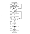
血圧および脈拍数の測定は、血圧計1のCPU100によって、図2のフローに従って行われる。
The blood pressure and pulse rate are measured by the
本実施形態での血圧の測定方法の説明に先立ち、一般的なオシロメトリック法による血圧測定の原理について説明する。 Prior to the description of the blood pressure measurement method in the present embodiment, the principle of blood pressure measurement by a general oscillometric method will be described.
一般的なオシロメトリック法に従って血圧を測定する場合、次のような動作が行なわれる。すなわち、被験者の測定部位に予めカフを巻き付けておき、測定時には、ポンプ・弁を制御して、カフ圧を最高血圧より高く加圧し、その後徐々に減圧していく。この減圧する過程において、測定部位の動脈で発生する動脈容積の変動をカフを介して、圧力センサで脈波信号として検出する。その時のカフ圧と検出した動脈容積の変動の大きさ(脈波信号の振幅)を利用して最高血圧(収縮期血圧:Systolic Blood Pressure)と最低血圧(拡張期血圧:Diastolic Blood Pressure)とを算出することにより、血圧が測定される。 When blood pressure is measured according to a general oscillometric method, the following operation is performed. In other words, a cuff is wound around the measurement site of the subject in advance, and at the time of measurement, the pump / valve is controlled to increase the cuff pressure higher than the maximum blood pressure, and then gradually reduce the pressure. In the process of reducing the pressure, a change in the arterial volume generated in the artery at the measurement site is detected as a pulse wave signal by the pressure sensor through the cuff. The systolic blood pressure and systolic blood pressure (diastolic blood pressure) are calculated using the cuff pressure at that time and the detected amplitude of the arterial volume (the amplitude of the pulse wave signal). By calculating, blood pressure is measured.
具体的には、まず、この例では被験者が血圧計1の電源スイッチ52AをONにして動作状態にさせる(ステップST1)。すると、CPU100は、処理用メモリ領域を初期化し、弁駆動回路330に制御信号を出力する。弁駆動回路330は、制御信号に基づいて、弁33を開放してカフ20の流体袋22内の空気を排気する。続いて、圧力センサ31の0mmHgの調整を行う制御を行う(ステップST2)。
Specifically, in this example, first, in this example, the subject turns on the
次に、被験者は、カフ20を被験者の手首に巻き付けて装着する。カフ20を巻き付けた後、被験者が血圧測定スイッチ52Bを押した場合(ステップST3でYES)、CPU100は、上記オシロメトリック法に従って血圧の測定を開始する制御を行う(ステップST4)。
Next, the subject wraps the cuff 20 around the wrist of the subject and wears it. When the subject presses the blood
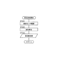
図3に示すように、血圧測定において、まず、CPU100は、弁駆動回路330を介して弁33を閉鎖し、その後、ポンプ駆動回路320を介してポンプ32を駆動して、流体袋22に空気を送る制御を行う。これにより、流体袋22を膨張させるとともにカフ圧を徐々に加圧していく(ステップST101)。
As shown in FIG. 3, in the blood pressure measurement, first, the
カフ圧が加圧されて所定の圧力に達すると(ステップST102でYES)、CPU100は、ポンプ駆動回路320を介してポンプ32を停止し、その後、弁駆動回路330を介して弁33を徐々に開放する制御を行う。これにより、流体袋22を収縮させるとともにカフ圧を徐々に減圧していく(ステップST103)。
When the cuff pressure is increased and reaches a predetermined pressure (YES in step ST102), the
ここで、所定の圧力とは、収縮期血圧よりも十分高い圧力(例えば、収縮期血圧+30mmHg)であり、予めメモリ51に記憶されているか、カフ圧の加圧中にCPU100が収縮期血圧を所定の算出式により推定して決定する。
Here, the predetermined pressure is a pressure sufficiently higher than the systolic blood pressure (for example, systolic blood pressure + 30 mmHg), and is stored in the
上記減圧過程において、圧力センサ31が手首の動脈で発生する容積変化をカフ20を介して圧脈波信号として検出する。CPU100は、この圧脈波信号に基づいて、オシロメトリック法による所定のアルゴリズムを適用して血圧値を算出する(ステップST104)。なお、血圧の算出は、減圧過程に限らず、加圧過程において行われてもよい。
In the decompression process, the
血圧値を算出して決定すると(ステップST105でYES)、CPU100は、算出した血圧値を表示器50へ表示し(ステップST106)、血圧値をメモリ51へ保存する制御を行う(ステップST107)。
When the blood pressure value is calculated and determined (YES in step ST105), the
次に、CPU100は、弁駆動回路330を介して弁33を開放し、カフ20の流体袋22内の空気を排気する制御を行う(ステップST108)。
Next, the
次に、図2に示すように、CPU100は、上記電源スイッチ52Aが押されなければ(ステップST5でNO)、ステップST3に戻り、上記電源スイッチ52Aが押されると、測定を終了する。
Next, as shown in FIG. 2, if the
一方、被験者が血圧測定スイッチ52Bを押さなかった場合(ステップST3でNO)、CPU100は、脈拍測定を開始する制御を行う(ステップST6)。
On the other hand, when the subject does not press blood
図4に示すように、脈拍測定において、まず、CPU100は、脈波検出回路410の発光素子駆動回路を介して発光素子411を駆動させ、発光素子411を発光させる制御を行う(ステップST201)。なお、発光素子411の駆動周波数としては、検出すべき動脈の容積の変動に含まれる周波数成分(おおよそ30Hz)よりも十分に高い周波数(たとえば3kHz程度)とすることにより、より精緻に動脈の容積の変動を検出できる。
As shown in FIG. 4, in the pulse measurement, first, the
発光素子411から上記手首中に延在する動脈に照射された光は、動脈によって反射され、この反射光を受光素子412が受光し、受光した光の光量に応じた出力信号を出力する。上記受光量検出回路は、受光素子412からの出力信号に基づいて電圧信号を生成し、CPU100へ出力する。CPU100は、この電圧信号に基づいて、所定のアルゴリズムを適用して脈拍数を算出し(ステップST202)、算出した脈拍数をメモリ51に記憶する制御を行う(ステップST203)。
The light emitted from the light emitting element 411 to the artery extending into the wrist is reflected by the artery, the light receiving element 412 receives the reflected light, and outputs an output signal corresponding to the amount of the received light. The received light amount detection circuit generates a voltage signal based on an output signal from the light receiving element 412 and outputs the voltage signal to the
次に、図2に示すように、CPU100は、脈拍数算出動作時間を測るタイマーカウントを増加させる制御を行う(ステップST7)。CPU100は、脈波が検出されて、脈拍があると判断すると(ステップST8でYES)、タイマーカウントをリセットする制御を行う(ステップST9)。
Next, as shown in FIG. 2, the
次に、CPU100は、上記電源スイッチ52Aが押されなければ(ステップST5でNO)、ステップST3に戻り、上記電源スイッチ52Aが押されると、測定を終了する。
Next, if the
一方、CPU100は、脈波が検出されなければ、脈拍がないと判断し(ステップST8でNO)、さらに、2分以上継続して脈波が検出されない場合(ステップST10でNO)、表示器50に異常を表示させる制御を行う(ステップST11)。次に、CPU100は、メモリ51に異常である旨を示すフラグを残す制御を行って(ステップST12)、測定を終了する。
On the other hand, if no pulse wave is detected,
図5は、ポンプ駆動回路320のブロック構成を示している。このポンプ駆動回路320は、昇圧部としての昇圧レギュレータ62と、Hブリッジ部としてのHブリッジ回路63とを有している。
FIG. 5 shows a block configuration of the
昇圧レギュレータ62は、概ね図6Aに示すように、入力端子71と出力端子76との間に直列に接続されたリアクタンス72およびダイオード73と、リアクタンス72とダイオード73との接続点と接地電位との間に接続されたスイッチング素子(この例では、MOSFET;Metal-Semiconductor-Oxide Field Effect Transistor;MOS型電界効果トランジスタ)74と、昇圧制御部75とを有している。
As shown in FIG. 6A, the
この昇圧レギュレータ62は、入力端子71に電源部(電池)53からの第1のDC電圧V1(この例では3V)を受ける。そして、昇圧制御部75の制御信号CGに応じてスイッチング素子74がオン、オフ制御されることにより、第1のDC電圧V1を昇圧して第2のDC電圧V2として出力端子76に出力する。第2のDC電圧V2は、昇圧制御部75へフィードバック信号FBとして戻される。このフィードバック信号FBに基づいて、第2のDC電圧V2が目標値になるように、昇圧制御部75の制御信号CGによって、スイッチング素子74のオン、オフが制御される。第2のDC電圧V2のための目標値は、図5中に示すCPU100からの昇圧制御信号CTL1によって設定される。
The
具体的には、CPU100からの昇圧制御信号CTL1はPWM信号であり、昇圧レギュレータ62は、そのPWM信号のパルス幅に応じて、第2のDC電圧V2を可変して目標値に制御して出力する。これにより、例えば第2のDC電圧V2を細かく、0.1V単位で変化(上昇または下降)させることができる。
Specifically, the boost control signal CTL1 from the
図6Aにおける第2のDC電圧V2から昇圧制御部(昇圧IC)75のフィードバック信号FBが入力される端子までの構成について図6Bを用いて詳述する。昇圧レギュレータ62は、一端がフィードバック信号FBに接続される固定抵抗11と、昇圧制御信号CTL1がゲートに入力され、固定抵抗11の他端にドレインが直列に接続されるFET14と、一端がFET14のソースと直列に接続され、他端が接地されている抵抗13と、昇圧制御信号CTL1発生部とFET14のゲートとの間の経路に対して一端が並列に接続され、他端が接地されている抵抗15及び抵抗15と同様に接続されるコンデンサ16と、昇圧制御信号CTL1発生部とFET14のゲートとの間の経路に対して直列に接続される抵抗17と、を有する。ここで、固定抵抗11がクレームの「第2の抵抗部」、FET14と抵抗13とを含む可変抵抗部12がクレームの「第1の抵抗部」に相当する。
The configuration from the second DC voltage V2 in FIG. 6A to the terminal to which the feedback signal FB of the boost control unit (boost IC) 75 is input will be described in detail with reference to FIG. 6B. The
昇圧制御信号CTL1は例えばCPUから出力されるPWM信号であり、通常デューティ比が50%の矩形波である。昇圧制御信号CTL1は、抵抗15と、抵抗17との分圧により出力レベルが調整され、抵抗15及びコンデンサ16により信号が平滑化される。
The boost control signal CTL1 is a PWM signal output from the CPU, for example, and is a rectangular wave with a normal duty ratio of 50%. The boost control signal CTL1 is adjusted in output level by voltage division between the
次に、平滑化された電圧(DC電圧)は、FET14のゲートに入力される。ここで、昇圧制御信号CTL1のデューティ比を増減させることで、平滑化された電圧(DC電圧)のレベルが増減するため、可変抵抗部12の抵抗値(FET14のインピーダンスから導きだされる等価的な抵抗値)を増減させることができる。
Next, the smoothed voltage (DC voltage) is input to the gate of the
昇圧IC75に印加されるフィードバック信号FBの電圧は、第2のDC電圧V2を固定抵抗11と可変抵抗部12との分圧比(固定抵抗11の抵抗値/(固定抵抗11の抵抗値+可変抵抗部12の抵抗値))によって分圧させた電圧として決定される。この電圧を昇圧IC75に帰還させることで、該分圧比に応じた第2のDC電圧の可変出力が可能となる。
The voltage of the feedback signal FB applied to the
このようにしているので、ポンプの駆動電圧の調整を容易に行うことができる。また、ポンプ最適な圧力を吐出するよう、安定して動作させることができる。 Since it is doing in this way, adjustment of the drive voltage of a pump can be performed easily. In addition, the pump can be stably operated so as to discharge the optimum pressure.
Hブリッジ回路63は、図7に示すように、昇圧レギュレータ62が出力した第2のDC電圧V2に対応する高電位(電位V2)とこの高電位よりも低い基準電位としての接地電位(電位ゼロ)との間に、直列に接続された2個のスイッチング素子(この例ではNPN型バイポーラトランジスタ)81,82を含む第1の直列回路63Aを有している。また、同様に、第2のDC電圧V2に対応する高電位V2と接地電位(電位ゼロ)との間に、直列に接続された2個のスイッチング素子(この例ではNPN型バイポーラトランジスタ)83,84を含む第2の直列回路63Bを有している。各スイッチング素子81,82,83,84は、ブリッジ制御信号GSW1,GSW2,GSW3,GSW4がH(高)レベルになるとオンし、ブリッジ制御信号GSW1,GSW2,GSW3,GSW4がL(低)レベルになるとオフする。
As shown in FIG. 7, the
CPU100からのブリッジ制御信号GSW1,GSW2,GSW3,GSW4(図5では、これらを包括的に「CTL2」として示す。)によって、第1の直列回路63Aの2個のスイッチング素子81,82、第2の直列回路63Bの2個のスイッチング素子83,84は、それぞれ後に詳述するようにオン、オフ制御される。この結果、第1の直列回路63Aの2個のスイッチング素子81,82の間の第1の接続点O1と、第2の直列回路63Bの2個のスイッチング素子83,84の間の第2の接続点O2との間に生じる電圧(Vout)が、上記ポンプ32を駆動するための駆動電圧として用いられる。
By the bridge control signals GSW1, GSW2, GSW3, and GSW4 from the CPU 100 (in FIG. 5, these are collectively indicated as “CTL2”), the two switching
また、CPU100が出力するブリッジ制御信号GSW1,GSW2,GSW3,GSW4によれば、PWM(Pulse Width Modulation;パルス幅変調)信号としてオン、オフの細かな制御が可能になり、例えば100Hz単位でポンプのための駆動周波数の細かな制御ができる。
Further, according to the bridge control signals GSW1, GSW2, GSW3, and GSW4 output from the
上記から分かるように、上記ポンプ32と、ポンプ駆動回路320と、制御部としてのCPU100とが、ポンプ駆動システムを構成している。
As can be seen from the above, the
なお、図5の上部には、理解の容易のために、電源部(電池)53からの第1のDC電圧V1、昇圧レギュレータ62が出力する第2のDC電圧V2、ポンプ32に印加される駆動電圧(O1−O2端子間電圧)Voutの波形を模式的に表している。
In the upper part of FIG. 5, for easy understanding, the first DC voltage V <b> 1 from the power supply unit (battery) 53, the second DC voltage V <b> 2 output from the
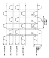
図9は、CPU100からの各スイッチング素子81,82,83,84に対するブリッジ制御信号GSW1,GSW2,GSW3,GSW4およびポンプ32に印加される駆動電圧(O1−O2端子間電圧)Voutの波形の一例として、最も基本的な動作波形を具体的に示している。図9において、(a)〜(d)は、時間tの経過に伴って、ブリッジ制御信号GSW1,GSW2,GSW3,GSW4のレベルがそれぞれHレベルとLレベルとの間で遷移することを示し、(e)は、それらのブリッジ制御信号GSW1,GSW2,GSW3,GSW4のレベルの変化に伴って、O1−O2端子間電圧Voutが変化することを表している(図10、図11、図12、図13において同様。)。なお、この例では、O1端子がO2端子よりも高電位となる期間を「プラス電圧印加期間」と呼び、O1端子がO2端子よりも低電位となる期間を「マイナス電圧印加期間」と呼ぶ。
FIG. 9 shows an example of the waveform of the bridge control signals GSW1, GSW2, GSW3, GSW4 from the
この図9の動作波形では、第1の直列回路63Aの2個のスイッチング素子81,82は相補的に、つまり交互に矩形波によってオン、オフ制御されている(図9(a),(b))。これとともに、第2の直列回路63Bの2個のスイッチング素子83,84は、第1の直列回路63Aの2個のスイッチング素子81,82のオン、オフ制御とは逆の位相で相補的に矩形波によってオン、オフ制御されている(図9(c),(d))。したがって、スイッチング素子81,84が互いに同じタイミングでオン状態、オフ状態になり、それとは逆の位相で、スイッチング素子82,83が互いに同じタイミングでオン状態、オフ状態になっている。
In the operation waveform of FIG. 9, the two switching
この結果、図9(e)に示すように、ポンプ32に印加される駆動電圧(O1−O2端子間電圧)Voutの波形は、昇圧レギュレータ62が出力する第2のDC電圧をV2(>0)としたとき、+V2が印加されたプラス電圧印加期間T1と−V2が印加されたマイナス電圧印加期間T2とを周期的に交互に繰り返す波形となる。プラス電圧印加期間T1とマイナス電圧印加期間T2との繰り返し周期は、ポンプ32としての圧電ポンプ(より正確には、圧電素子)の共振周期Tと一致されている。なお、この例では、圧電ポンプの共振周波数は約100kHzであり、したがって、共振周期Tは約10μ秒である。
As a result, as shown in FIG. 9E, the waveform of the drive voltage (O1-O2 terminal voltage) Vout applied to the
これにより、ポンプ32としての圧電ポンプに、駆動電圧Voutとして周波数が共振周期Tと一致した交流電圧が印加される。したがって、圧電ポンプが動作して、カフ20の流体袋22に空気を送ることができる。
As a result, an AC voltage whose frequency matches the resonance period T is applied to the piezoelectric pump as the
このようにした場合、圧電ポンプを駆動するために、例えば50Vp−p(ピーク・ツー・ピーク電圧)程度の振幅をもつ駆動電圧を得るためには、昇圧レギュレータ62は第2のDC電圧V2として、駆動電圧として要求される振幅の半分の電圧、つまり最大で25Vを出力すれば足りる。したがって、電源が、例えば3Vの乾電池(1.5V×2個)で構成され得る。また、昇圧レギュレータ62が、小型で低コストに構成され得る。さらに、Hブリッジ回路63自体も、比較的部品点数が少ないことから、小型で低コストに構成され得る。
In this case, in order to obtain a drive voltage having an amplitude of, for example, about 50 Vp-p (peak-to-peak voltage) in order to drive the piezoelectric pump, the
また、第1の直列回路63Aの2個のスイッチング素子81,82、第2の直列回路63Bの2個のスイッチング素子83,84をそれぞれオン、オフ制御するために、CPU100は、ブリッジ制御信号GSW1,GSW2,GSW3,GSW4として4つのデジタル信号を出力すれば足り、負荷が小さい。したがって、CPU100は、特段の新たな部品を設けることなく、例えば血圧計1を構成する既存のCPU(Central Processing Unit;中央演算処理装置)によって構成され得る。また、CPU100が出力するブリッジ制御信号GSW1,GSW2,GSW3,GSW4によれば、既述のようにオン、オフの細かな制御が可能になり、例えば100Hz単位でポンプ32のための駆動周波数の細かな制御ができる。したがって、例えば圧電ポンプの特性ばらつき(特に、共振周波数のばらつき)に容易に適合することができる。
In order to turn on and off the two switching
また、既述のように、昇圧レギュレータ62は、CPU100が出力する昇圧制御信号CTL1に応じて、第2のDC電圧V2を細かく、例えば0.1V単位で上昇させることができる。したがって、例えばポンプ32としての圧電ポンプによって、等速加圧(例えば10mmHg/sec)を容易に行うことができる。
Further, as described above, the
したがって、この血圧計1によれば、小型化、低コスト化、高性能化を達成できる。
Therefore, according to the
図10は、CPU100からの各スイッチング素子81,82,83,84に対するブリッジ制御信号GSW1,GSW2,GSW3,GSW4およびポンプ32に印加される駆動電圧(O1−O2端子間電圧)Voutの波形の別の例を示している。
FIG. 10 shows different waveforms of the bridge control signals GSW1, GSW2, GSW3, and GSW4 from the
この図10の動作波形では、図9の動作波形に対して、或るスイッチング素子のオン期間とこのオン期間に続く別のスイッチング素子のオン期間との間に、いずれのスイッチング素子もオフしている休止期間tddが設けられている点が異なっている。 In the operation waveform of FIG. 10, with respect to the operation waveform of FIG. 9, any switching element is turned off between the ON period of a certain switching element and the ON period of another switching element following this ON period. The difference is that there is a rest period tdd.
具体的には、図10(a)〜(d)に示すように、図9の動作波形に対して、ブリッジ制御信号GSW1,GSW4がHレベルからLレベルへ遷移するタイミングがtddだけ早くなり、したがって、スイッチング素子81,84がオン状態からオフ状態へ遷移するタイミングがtddだけ早くなっている。同様に、ブリッジ制御信号GSW2,GSW3がHレベルからLレベルへ遷移するタイミングがtddだけ早くなり、したがって、スイッチング素子82,83がオン状態からオフ状態へ遷移するタイミングがtddだけ早くなっている。
Specifically, as shown in FIGS. 10A to 10D, the timing at which the bridge control signals GSW1 and GSW4 transition from the H level to the L level is earlier than the operation waveform of FIG. 9 by tdd, Therefore, the timing at which the
これにより、図10(e)に示すように、ポンプ32に印加される駆動電圧(O1−O2端子間電圧)Voutの波形において、プラス電圧印加期間T1とマイナス電圧印加期間T2との間に、印加電圧ゼロの期間(tdd)が生じている。
Accordingly, as shown in FIG. 10E, in the waveform of the drive voltage (O1-O2 terminal voltage) Vout applied to the
この結果、駆動電圧Voutの反転時、つまりプラス電圧印加期間T1の開始時、マイナス電圧印加期間T2の開始時に、ポンプ32としての圧電ポンプに対する突入電流が制限される。したがって、駆動電圧Voutの反転時における電力消費が抑制され、省エネルギが実現される。
As a result, the inrush current to the piezoelectric pump as the
図11は、CPU100からの各スイッチング素子81,82,83,84に対するブリッジ制御信号GSW1,GSW2,GSW3,GSW4およびポンプ32に印加される駆動電圧(O1−O2端子間電圧)Voutの波形のさらに別の例を示している。
FIG. 11 shows the waveform of the bridge control signals GSW1, GSW2, GSW3, GSW4 from the
この図11の動作波形では、図9の動作波形に対して、各スイッチング素子81,82,83,84を、オフ状態からオン状態へ、またオン状態からオフ状態へ、それぞれ有限の遷移期間をもって遷移させる点が異なっている。
In the operation waveform of FIG. 11, the switching
具体的には、CPU100とHブリッジ回路63との間に、図8に示すようなフィルタ回路90を設ける。このフィルタ回路90は、CPU100側の入力端子91とHブリッジ回路63側の出力端子95との間に設けられた抵抗92と、出力端子95と接地電位との間に、直列に接続されたアナログスイッチ93とコンデンサ94を有している。アナログスイッチ93は、CPU100からの遷移制御信号CTL3によってオン、オフ制御され、オン状態で有限なオン抵抗を示す。
Specifically, a
CPU100からのブリッジ制御信号GSW1,GSW2,GSW3,GSW4がなす矩形波98が、端子91に入力されると、アナログスイッチ93の有限なオン抵抗を通してコンデンサ94が充電される。この結果、出力端子95から、台形状の波形99が出力される。この波形99は、有限の遷移期間(t0〜t0′)をかけてLレベルからHレベルへ遷移し、有限の遷移期間(t1′〜t1)をかけてHレベルからLレベルへ遷移する。
When a
図11(a)〜(d)に示すように、CPU100からのブリッジ制御信号GSW1,GSW2,GSW3,GSW4は、いずれも上述のような台形状の波形99になっている。
As shown in FIGS. 11A to 11D, the bridge control signals GSW1, GSW2, GSW3, and GSW4 from the
これにより、図11(e)に示すように、ポンプ32に印加される駆動電圧(O1−O2端子間電圧)Voutの波形も、プラス電圧印加期間T1、マイナス電圧印加期間T2でそれぞれ台形状の波形になっている。すなわち、駆動電圧Voutは、プラス電圧印加期間T1の開始時に、有限の遷移期間(t0〜t0′)をかけてゼロから+V2へ遷移し、プラス電圧印加期間T1の終了時に、有限の遷移期間(t1′〜t1)をかけて+V2からゼロへ遷移する。同様に、駆動電圧Voutは、マイナス電圧印加期間T2の開始時に、有限の遷移期間t0〜t0′をかけてゼロから−V2へ遷移し、マイナス電圧印加期間T2の終了時に、有限の遷移期間t1′〜t1をかけて−V2からゼロへ遷移する。
As a result, as shown in FIG. 11E, the waveform of the drive voltage (O1-O2 terminal voltage) Vout applied to the
この結果、駆動電圧Voutの反転時、つまりプラス電圧印加期間T1の開始時、マイナス電圧印加期間T2の開始時に、ポンプ32としての圧電ポンプに対する突入電流が制限される。したがって、駆動電圧Voutの反転時における電力消費が抑制され、省エネルギが実現される。
As a result, the inrush current to the piezoelectric pump as the
図12は、CPU100からの各スイッチング素子81,82,83,84に対するブリッジ制御信号GSW1,GSW2,GSW3,GSW4およびポンプ32に印加される駆動電圧(O1−O2端子間電圧)Voutの波形のさらに別の例を示している。
FIG. 12 shows the waveform of the bridge control signals GSW1, GSW2, GSW3, GSW4 from the
この図12の動作波形は、図10の動作波形と図11の動作波形とを組み合わせたものである。すなわち、図12(a)〜(d)に示すように、図10の動作波形と同様に、或るスイッチング素子のオン期間とこのオン期間に続く別のスイッチング素子のオン期間との間に、いずれのスイッチング素子もオフしている休止期間tddが設けられている。しかも、図11の動作波形と同様に、各スイッチング素子81,82,83,84を、オフ状態からオン状態へ、またオン状態からオフ状態へ、それぞれ有限の遷移期間をもって遷移させている。
The operation waveform of FIG. 12 is a combination of the operation waveform of FIG. 10 and the operation waveform of FIG. That is, as shown in FIGS. 12A to 12D, similarly to the operation waveform of FIG. 10, between the ON period of one switching element and the ON period of another switching element following this ON period, A pause period tdd is provided in which all the switching elements are off. Moreover, similarly to the operation waveform of FIG. 11, the switching
これにより、図12(e)に示すように、ポンプ32に印加される駆動電圧(O1−O2端子間電圧)Voutでは、プラス電圧印加期間T1とマイナス電圧印加期間T2との間に、電圧ゼロの期間(tdd)が生じている。しかも、ポンプ32に印加される駆動電圧(O1−O2端子間電圧)Voutの波形は、プラス電圧印加期間T1、マイナス電圧印加期間T2でそれぞれ台形状の波形になっている。
As a result, as shown in FIG. 12E, in the drive voltage (O1-O2 terminal voltage) Vout applied to the
この結果、駆動電圧Voutの反転時、つまりプラス電圧印加期間T1の開始時、マイナス電圧印加期間T2の開始時に、ポンプ32としての圧電ポンプに対する突入電流がさらに制限される。したがって、駆動電圧Voutの反転時における電力消費がさらに抑制され、省エネルギが実現される。
As a result, the inrush current to the piezoelectric pump as the
図13は、上記ポンプ32として、圧電ポンプに代えて、DCモータ駆動式ロータリポンプを用いる場合の動作波形を示している。
FIG. 13 shows an operation waveform when a DC motor-driven rotary pump is used as the
この図13の動作波形では、第1の直列回路63Aの2個のスイッチング素子81,82のうち高電位側のスイッチング素子81は矩形波によってオン、オフ制御され、接地電位側のスイッチング素子82はオフ状態に維持されている(図13(a),(b))。これとともに、第2の直列回路63Bの2個のスイッチング素子83,84のうち高電位側のスイッチング素子83はオフ状態に維持され、接地電位側のスイッチング素子84は第1の直列回路63Aの高電位側のスイッチング素子81のオン、オフ制御とは逆の位相で矩形波によってオン、オフ制御されている(図13(c),(d))。
In the operation waveform of FIG. 13, among the two switching
この結果、図13(e)に示すように、ポンプ32に印加される駆動電圧(O1−O2端子間電圧)Voutの波形は、昇圧レギュレータ62が出力する第2のDC電圧をV2(>0)としたとき、+V2が印加されたプラス電圧印加期間Δt1とゼロ電圧が印加された期間Δt2とを周期的に交互に繰り返す波形となる。
As a result, as shown in FIG. 13E, the waveform of the drive voltage (O1-O2 terminal voltage) Vout applied to the
これにより、ポンプ32としてのDCモータ駆動式ロータリポンプに、駆動電圧Voutとして周期的なプラス電圧が印加される。したがって、モータ駆動式ロータリポンプが動作して、カフ20の流体袋22に空気を送ることができる。
As a result, a periodic positive voltage is applied to the DC motor-driven rotary pump as the
DCモータ駆動式ロータリポンプからなるポンプ32の駆動は、第2のDC電圧V2を固定し、デューティ比Δt1/(Δt1+Δt2)を可変することによって、制御される。
The driving of the
上述のように、この実施形態の血圧計およびポンプ駆動システムによれば、小型化、低コスト化、高性能化を達成できる。特に、電源を例えば3Vの乾電池(1.5V×2個)で構成できる点、また、ポンプ32の駆動電圧Voutの大きさV2と周波数をCPU100によって容易に制御できる点が注目される。さらに、ポンプ32として圧電ポンプとロータリポンプとのいずれを採用しても駆動できる点が注目される。
As described above, the sphygmomanometer and the pump drive system of this embodiment can achieve downsizing, cost reduction, and high performance. In particular, it is noted that the power source can be configured by, for example, a 3V dry battery (1.5V × 2), and the magnitude V2 and frequency of the drive voltage Vout of the
なお、上述の実施形態は例示に過ぎず、この発明の範囲から逸脱することなく種々の変形が可能である。 The above-described embodiment is merely an example, and various modifications can be made without departing from the scope of the present invention.
1 血圧計
20 血圧測定用カフ
62 昇圧レギュレータ
63 Hブリッジ回路
100 CPU
320 ポンプ駆動回路
1 Blood Pressure Monitor 20 Blood
320 Pump drive circuit
Claims (11)
上記ポンプを駆動するためのポンプ駆動回路と、
血圧測定のために上記ポンプ駆動回路を制御する制御部とを少なくとも備え、
上記ポンプ駆動回路は、
電源からの第1のDC電圧を昇圧して第2のDC電圧として出力する昇圧部と、
上記第2のDC電圧に対応する高電位とこの高電位よりも低い基準電位との間に、直列に接続された2個のスイッチング素子をそれぞれ含む第1、第2の直列回路を有するHブリッジ部とを備え、
上記制御部からのブリッジ制御信号によって、上記第1の直列回路の上記2個のスイッチング素子、上記第2の直列回路の上記2個のスイッチング素子は、それぞれオン、オフ制御され、
上記第1の直列回路の上記2個のスイッチング素子の間の第1の接続点と、上記第2の直列回路の上記2個のスイッチング素子の間の第2の接続点との間に生じる電圧が、上記ポンプを駆動するための駆動電圧として用いられることを特徴とする血圧計。 A pump that sends fluid to a blood pressure cuff;
A pump drive circuit for driving the pump;
A control unit that controls the pump drive circuit for blood pressure measurement,
The pump drive circuit is
A boosting unit that boosts the first DC voltage from the power supply and outputs the first DC voltage as a second DC voltage;
An H-bridge having first and second series circuits each including two switching elements connected in series between a high potential corresponding to the second DC voltage and a reference potential lower than the high potential With
By the bridge control signal from the control unit, the two switching elements of the first series circuit and the two switching elements of the second series circuit are respectively turned on and off,
A voltage generated between a first connection point between the two switching elements of the first series circuit and a second connection point between the two switching elements of the second series circuit. Is used as a drive voltage for driving the pump.
上記昇圧部は、上記制御部からの昇圧制御信号に応じて、上記第2のDC電圧を可変して出力する昇圧レギュレータであることを特徴とする血圧計。 The sphygmomanometer according to claim 1,
The sphygmomanometer, wherein the boosting unit is a boosting regulator that variably outputs the second DC voltage in accordance with a boosting control signal from the control unit.
上記制御部からの昇圧制御信号はPWM信号であり、
上記昇圧部としての昇圧レギュレータは、上記PWM信号のパルス幅に応じて、上記第2のDC電圧を可変して出力することを特徴とする血圧計。 The sphygmomanometer according to claim 2,
The boost control signal from the control unit is a PWM signal,
The sphygmomanometer, wherein the boosting regulator as the boosting unit variably outputs the second DC voltage according to the pulse width of the PWM signal.
上記ポンプは圧電ポンプであり、
上記制御部からのブリッジ制御信号によって、上記第1の直列回路の上記2個のスイッチング素子は相補的にオン、オフ制御されるとともに、上記第2の直列回路の上記2個のスイッチング素子は、上記第1の直列回路の上記2個のスイッチング素子のオン、オフ制御とは逆の位相で相補的にオン、オフ制御されることを特徴とする血圧計。 The sphygmomanometer according to any one of claims 1 to 3,
The pump is a piezoelectric pump,
The two switching elements of the first series circuit are complementarily turned on and off by the bridge control signal from the control unit, and the two switching elements of the second series circuit are A sphygmomanometer, wherein the two switching elements of the first series circuit are complementarily turned on / off in a phase opposite to that of the on / off control.
上記制御部は、上記第1、第2の直列回路の或るスイッチング素子のオン期間とこのオン期間に続く別のスイッチング素子のオン期間との間に、いずれのスイッチング素子もオフしている休止期間を設定する制御を行うことを特徴とする血圧計。 The sphygmomanometer according to claim 4,
The control unit is in a state where any switching element is turned off between an on period of a certain switching element of the first and second series circuits and an on period of another switching element following the on period. A sphygmomanometer characterized by performing control for setting a period.
上記制御部は、上記第1、第2の直列回路の各スイッチング素子を、オフ状態からオン状態へ、またオン状態からオフ状態へ、それぞれ有限の遷移期間をかけて遷移させる制御を行うことを特徴とする血圧計。 The sphygmomanometer according to claim 4 or 5,
The control unit performs control for transitioning the switching elements of the first and second series circuits from an off state to an on state and from an on state to an off state over a finite transition period. Sphygmomanometer characterized.
上記ポンプはロータリポンプであり、
上記制御部からのブリッジ制御信号によって、上記第1の直列回路の上記2個のスイッチング素子のうち上記高電位側のスイッチング素子はオン、オフ制御され、上記基準電位側のスイッチング素子はオフ状態に維持されるとともに、上記第2の直列回路の上記2個のスイッチング素子のうち上記高電位側のスイッチング素子はオフ状態に維持され、上記基準電位側のスイッチング素子は上記第1の直列回路の上記高電位側のスイッチング素子のオン、オフ制御とは逆の位相でオン、オフ制御されることを特徴とする血圧計。 The sphygmomanometer according to claim 1,
The pump is a rotary pump,
Of the two switching elements of the first series circuit, the switching element on the high potential side is turned on and off by the bridge control signal from the control unit, and the switching element on the reference potential side is turned off. Among the two switching elements of the second series circuit, the high-potential side switching element is maintained in the OFF state, and the reference potential-side switching element is the above-described first series circuit. A sphygmomanometer, wherein on / off control is performed at a phase opposite to on / off control of a switching element on a high potential side.
上記ポンプを駆動するためのポンプ駆動回路と、
上記ポンプ駆動回路を制御する制御部とを少なくとも備え、
上記ポンプ駆動回路は、
電源からの第1のDC電圧を昇圧して第2のDC電圧として出力する昇圧部と、
上記第2のDC電圧に対応する高電位とこの高電位よりも低い基準電位との間に、直列に接続された2個のスイッチング素子をそれぞれ含む第1、第2の直列回路を有するHブリッジ部とを備え、
上記制御部からの昇圧制御信号はPWM信号であり、上記昇圧部は、抵抗とFETとを有する上記PWM信号のパルス幅に応じて抵抗値を可変させる第1の抵抗部と、第2の抵抗部とを備え、上記第2のDC電圧を、上記第1の抵抗部と上記第2の抵抗部とで分圧して帰還させることで、上記第2のDC電圧の可変出力が可能な昇圧レギュレータであり、
上記制御部からのブリッジ制御信号によって、上記第1、第2の直列回路の上記2個のスイッチング素子はオン、オフ制御され、
上記第1の直列回路の上記2個のスイッチング素子の間の第1の接続点と、上記第2の直列回路の上記2個のスイッチング素子の間の第2の接続点との間に生じる電圧が、上記ポンプを駆動するための駆動電圧として用いられることを特徴とするポンプ駆動システム。 A pump,
A pump drive circuit for driving the pump;
A control unit for controlling the pump drive circuit,
The pump drive circuit is
A boosting unit that boosts the first DC voltage from the power supply and outputs the first DC voltage as a second DC voltage;
An H-bridge having first and second series circuits each including two switching elements connected in series between a high potential corresponding to the second DC voltage and a reference potential lower than the high potential With
The step-up control signal from the control unit is a PWM signal, and the step-up unit includes a first resistance unit that varies a resistance value according to a pulse width of the PWM signal having a resistor and an FET, and a second resistor. And a step-up regulator capable of variably outputting the second DC voltage by dividing and feeding back the second DC voltage between the first resistor and the second resistor. And
The two switching elements of the first and second series circuits are on / off controlled by a bridge control signal from the control unit,
A voltage generated between a first connection point between the two switching elements of the first series circuit and a second connection point between the two switching elements of the second series circuit. Is used as a driving voltage for driving the pump.
上記ポンプは圧電ポンプであり、
上記制御部からのブリッジ制御信号によって、上記第1の直列回路の上記2個のスイッチング素子は相補的にオン、オフ制御されるとともに、上記第2の直列回路の上記2個のスイッチング素子は、上記第1の直列回路の上記2個のスイッチング素子のオン、オフ制御とは逆の位相で相補的にオン、オフ制御されることを特徴とするポンプ駆動システム。 The pump drive system according to claim 8,
The pump is a piezoelectric pump,
The two switching elements of the first series circuit are complementarily turned on and off by the bridge control signal from the control unit, and the two switching elements of the second series circuit are A pump drive system, wherein the two switching elements of the first series circuit are complementarily turned on / off in a phase opposite to that of the on / off control.
上記制御部は、上記第1、第2の直列回路の或るスイッチング素子のオン期間とこのオン期間に続く別のスイッチング素子のオン期間との間に、いずれのスイッチング素子もオフしている休止期間を設定する制御を行うことを特徴とするポンプ駆動システム。 The pump drive system according to claim 9, wherein
The control unit is in a state where any switching element is turned off between an on period of a certain switching element of the first and second series circuits and an on period of another switching element following the on period. A pump drive system characterized by performing control for setting a period.
上記制御部は、上記第1、第2の直列回路の各スイッチング素子を、オフ状態からオン状態へ、またオン状態からオフ状態へ、それぞれ有限の遷移期間をかけて遷移させる制御を行うことを特徴とするポンプ駆動システム。 The pump drive system according to claim 9 or 10,
The control unit performs control for transitioning the switching elements of the first and second series circuits from an off state to an on state and from an on state to an off state over a finite transition period. Feature pump drive system.
Priority Applications (5)
| Application Number | Priority Date | Filing Date | Title |
|---|---|---|---|
| JP2012095287A JP5944727B2 (en) | 2012-04-19 | 2012-04-19 | Sphygmomanometer and pump drive system |
| DE112013002130.7T DE112013002130T5 (en) | 2012-04-19 | 2013-04-03 | Sphygmomanometer and pump drive system |
| CN201380020501.XA CN104254276B (en) | 2012-04-19 | 2013-04-03 | Sphygomanometer and drive system of pump |
| PCT/JP2013/060231 WO2013157394A1 (en) | 2012-04-19 | 2013-04-03 | Sphygmomanometer and pump driving system |
| US14/516,777 US9775526B2 (en) | 2012-04-19 | 2014-10-17 | Blood pressure meter and pump driving system |
Applications Claiming Priority (1)
| Application Number | Priority Date | Filing Date | Title |
|---|---|---|---|
| JP2012095287A JP5944727B2 (en) | 2012-04-19 | 2012-04-19 | Sphygmomanometer and pump drive system |
Publications (3)
| Publication Number | Publication Date |
|---|---|
| JP2013220288A JP2013220288A (en) | 2013-10-28 |
| JP2013220288A5 JP2013220288A5 (en) | 2015-06-11 |
| JP5944727B2 true JP5944727B2 (en) | 2016-07-05 |
Family
ID=49383359
Family Applications (1)
| Application Number | Title | Priority Date | Filing Date |
|---|---|---|---|
| JP2012095287A Active JP5944727B2 (en) | 2012-04-19 | 2012-04-19 | Sphygmomanometer and pump drive system |
Country Status (5)
| Country | Link |
|---|---|
| US (1) | US9775526B2 (en) |
| JP (1) | JP5944727B2 (en) |
| CN (1) | CN104254276B (en) |
| DE (1) | DE112013002130T5 (en) |
| WO (1) | WO2013157394A1 (en) |
Families Citing this family (9)
| Publication number | Priority date | Publication date | Assignee | Title |
|---|---|---|---|---|
| TWI670046B (en) * | 2016-03-29 | 2019-09-01 | 豪展醫療科技股份有限公司 | Measuring device and method for measuring emotional stress index and blood pressure detecting |
| JP6673505B2 (en) | 2017-01-20 | 2020-03-25 | 株式会社村田製作所 | Fluid control device and blood pressure monitor |
| WO2018168379A1 (en) * | 2017-03-16 | 2018-09-20 | 株式会社村田製作所 | Fluid control device and sphygmomanometer |
| CN107536605B (en) * | 2017-09-05 | 2020-05-05 | 广州视源电子科技股份有限公司 | PWM circuit duty ratio adjusting method, controller and blood pressure measuring device |
| CN107748589A (en) * | 2017-10-18 | 2018-03-02 | 京东方科技集团股份有限公司 | A kind of adjustable circuit of output voltage and its voltage adjusting method and display device |
| JP7055659B2 (en) * | 2018-02-15 | 2022-04-18 | 東芝テック株式会社 | Liquid circulation device and liquid discharge device |
| WO2019159501A1 (en) * | 2018-02-16 | 2019-08-22 | 株式会社村田製作所 | Fluid control device |
| TWI720876B (en) * | 2020-04-24 | 2021-03-01 | 研能科技股份有限公司 | Driving circuit system for driving piezoelectric pump |
| CN113143234B (en) * | 2021-04-13 | 2023-04-14 | 研和智能科技(杭州)有限公司 | Blood pressure measuring device and control method |
Family Cites Families (13)
| Publication number | Priority date | Publication date | Assignee | Title |
|---|---|---|---|---|
| JP2770295B2 (en) * | 1989-12-05 | 1998-06-25 | 株式会社産機 | Vibration transfer device |
| JP3622539B2 (en) | 1998-12-04 | 2005-02-23 | 松下電工株式会社 | Blood pressure measurement device using piezoelectric diaphragm pump |
| JP3595808B2 (en) * | 2002-07-11 | 2004-12-02 | コニカミノルタホールディングス株式会社 | Voltage generating circuit and driving device provided with the circuit |
| US7862514B2 (en) * | 2006-02-06 | 2011-01-04 | Welch Allyn, Inc. | Blood pressure measurement |
| JP2007259911A (en) * | 2006-03-27 | 2007-10-11 | Omron Healthcare Co Ltd | Device for measuring blood pressure |
| JP5151310B2 (en) | 2007-08-15 | 2013-02-27 | ソニー株式会社 | Piezoelectric element drive circuit and pump device |
| WO2009107008A2 (en) * | 2008-02-28 | 2009-09-03 | Koninklijke Philips Electronics, N.V. | Automated non-magnetic medical monitor using piezoelectric ceramic diaphragm devices |
| JP2009240151A (en) * | 2008-03-07 | 2009-10-15 | Seiko Epson Corp | Semiconductor device for controlling supply of driving signal |
| JP2010142783A (en) | 2008-12-22 | 2010-07-01 | Sanyo Electric Co Ltd | Voltage output driver |
| JP5028400B2 (en) * | 2008-12-22 | 2012-09-19 | 三洋電機株式会社 | Voltage output driver and piezoelectric pump |
| JP5740879B2 (en) * | 2009-09-18 | 2015-07-01 | 株式会社村田製作所 | Piezoelectric actuator drive circuit |
| US8371829B2 (en) * | 2010-02-03 | 2013-02-12 | Kci Licensing, Inc. | Fluid disc pump with square-wave driver |
| JP2012029793A (en) * | 2010-07-29 | 2012-02-16 | Omron Healthcare Co Ltd | Module for electronic sphygmomanometer, and electronic sphygmomanometer |
-
2012
- 2012-04-19 JP JP2012095287A patent/JP5944727B2/en active Active
-
2013
- 2013-04-03 DE DE112013002130.7T patent/DE112013002130T5/en active Pending
- 2013-04-03 WO PCT/JP2013/060231 patent/WO2013157394A1/en active Application Filing
- 2013-04-03 CN CN201380020501.XA patent/CN104254276B/en active Active
-
2014
- 2014-10-17 US US14/516,777 patent/US9775526B2/en active Active
Also Published As
| Publication number | Publication date |
|---|---|
| WO2013157394A1 (en) | 2013-10-24 |
| CN104254276B (en) | 2016-06-08 |
| CN104254276A (en) | 2014-12-31 |
| US20150038858A1 (en) | 2015-02-05 |
| US9775526B2 (en) | 2017-10-03 |
| JP2013220288A (en) | 2013-10-28 |
| DE112013002130T5 (en) | 2015-01-29 |
Similar Documents
| Publication | Publication Date | Title |
|---|---|---|
| JP5944727B2 (en) | Sphygmomanometer and pump drive system | |
| JP5884496B2 (en) | Blood pressure measuring device and method for controlling blood pressure measuring device | |
| JP5998486B2 (en) | Blood pressure measuring device and method for controlling blood pressure measuring device | |
| CA2739852C (en) | A method and apparatus for supplying energy to a medical device | |
| US20090168475A1 (en) | Converter power supply circuit and converter power supply driving method | |
| KR102012743B1 (en) | Power supply supporting device and method of supporting power supply to load | |
| US20220010791A1 (en) | Methods and devices for driving a piezoelectric pump | |
| WO2013157399A1 (en) | Blood pressure measuring device, control device in blood pressure measuring device, and control method of blood pressure measuring device | |
| WO2018142975A1 (en) | Fluid control device and blood pressure meter | |
| US11773835B2 (en) | Fluid control device and sphygmomanometer | |
| TW201223095A (en) | Switching power converter | |
| JP2014014556A (en) | Electronic sphygmomanometer and sphygmomanometry method | |
| JP6908137B2 (en) | Drive device and fluid control device | |
| JP2010011606A (en) | Power supply circuit using piezoelectric transformer | |
| JP5771769B2 (en) | Lighting device, lighting fixture, lighting system | |
| JP2000300662A (en) | Low-pressure continuing suction device of electrical type | |
| JP6035838B2 (en) | Piezoelectric pump control device, piezoelectric pump control method, piezoelectric pump control program, and blood pressure measurement device | |
| JP2012161162A (en) | Multiple voltage output type power supply device | |
| JP2017115792A (en) | Piezoelectric pump driving device and hemadynamometer provided with the same | |
| JP2015015983A (en) | Route measuring apparatus | |
| CN110213990A (en) | Fluid control device and sphygmomanometer | |
| AU2017201947B2 (en) | A method and apparatus for supplying energy to a medical device | |
| JP5046518B2 (en) | Piezoelectric drive circuit | |
| TWI518336B (en) | Output current measurement method of Chi - back power converter operating in discontinuous mode | |
| CN117337149A (en) | Drive circuit for blood pressure measurement and blood pressure measurement device |
Legal Events
| Date | Code | Title | Description |
|---|---|---|---|
| A521 | Request for written amendment filed |
Free format text: JAPANESE INTERMEDIATE CODE: A523 Effective date: 20150408 |
|
| A621 | Written request for application examination |
Free format text: JAPANESE INTERMEDIATE CODE: A621 Effective date: 20150408 |
|
| TRDD | Decision of grant or rejection written | ||
| A01 | Written decision to grant a patent or to grant a registration (utility model) |
Free format text: JAPANESE INTERMEDIATE CODE: A01 Effective date: 20160510 |
|
| A61 | First payment of annual fees (during grant procedure) |
Free format text: JAPANESE INTERMEDIATE CODE: A61 Effective date: 20160526 |
|
| R150 | Certificate of patent or registration of utility model |
Ref document number: 5944727 Country of ref document: JP Free format text: JAPANESE INTERMEDIATE CODE: R150 |
|
| R250 | Receipt of annual fees |
Free format text: JAPANESE INTERMEDIATE CODE: R250 |
|
| R250 | Receipt of annual fees |
Free format text: JAPANESE INTERMEDIATE CODE: R250 |
|
| R250 | Receipt of annual fees |
Free format text: JAPANESE INTERMEDIATE CODE: R250 |
|
| R250 | Receipt of annual fees |
Free format text: JAPANESE INTERMEDIATE CODE: R250 |
|
| R250 | Receipt of annual fees |
Free format text: JAPANESE INTERMEDIATE CODE: R250 |
|
| R250 | Receipt of annual fees |
Free format text: JAPANESE INTERMEDIATE CODE: R250 |