JP5941281B2 - System and method for ablating body tissue - Google Patents
System and method for ablating body tissue Download PDFInfo
- Publication number
- JP5941281B2 JP5941281B2 JP2011536608A JP2011536608A JP5941281B2 JP 5941281 B2 JP5941281 B2 JP 5941281B2 JP 2011536608 A JP2011536608 A JP 2011536608A JP 2011536608 A JP2011536608 A JP 2011536608A JP 5941281 B2 JP5941281 B2 JP 5941281B2
- Authority
- JP
- Japan
- Prior art keywords
- transducer
- transducer element
- heat sink
- tissue
- distal
- Prior art date
- Legal status (The legal status is an assumption and is not a legal conclusion. Google has not performed a legal analysis and makes no representation as to the accuracy of the status listed.)
- Active
Links
Images


Classifications
-
- A—HUMAN NECESSITIES
- A61—MEDICAL OR VETERINARY SCIENCE; HYGIENE
- A61B—DIAGNOSIS; SURGERY; IDENTIFICATION
- A61B8/00—Diagnosis using ultrasonic, sonic or infrasonic waves
- A61B8/44—Constructional features of the ultrasonic, sonic or infrasonic diagnostic device
- A61B8/4483—Constructional features of the ultrasonic, sonic or infrasonic diagnostic device characterised by features of the ultrasound transducer
- A61B8/4494—Constructional features of the ultrasonic, sonic or infrasonic diagnostic device characterised by features of the ultrasound transducer characterised by the arrangement of the transducer elements
-
- A—HUMAN NECESSITIES
- A61—MEDICAL OR VETERINARY SCIENCE; HYGIENE
- A61N—ELECTROTHERAPY; MAGNETOTHERAPY; RADIATION THERAPY; ULTRASOUND THERAPY
- A61N7/00—Ultrasound therapy
- A61N7/02—Localised ultrasound hyperthermia
- A61N7/022—Localised ultrasound hyperthermia intracavitary
-
- A—HUMAN NECESSITIES
- A61—MEDICAL OR VETERINARY SCIENCE; HYGIENE
- A61B—DIAGNOSIS; SURGERY; IDENTIFICATION
- A61B8/00—Diagnosis using ultrasonic, sonic or infrasonic waves
- A61B8/08—Detecting organic movements or changes, e.g. tumours, cysts, swellings
- A61B8/0883—Detecting organic movements or changes, e.g. tumours, cysts, swellings for diagnosis of the heart
-
- A—HUMAN NECESSITIES
- A61—MEDICAL OR VETERINARY SCIENCE; HYGIENE
- A61B—DIAGNOSIS; SURGERY; IDENTIFICATION
- A61B8/00—Diagnosis using ultrasonic, sonic or infrasonic waves
- A61B8/12—Diagnosis using ultrasonic, sonic or infrasonic waves in body cavities or body tracts, e.g. by using catheters
-
- A—HUMAN NECESSITIES
- A61—MEDICAL OR VETERINARY SCIENCE; HYGIENE
- A61B—DIAGNOSIS; SURGERY; IDENTIFICATION
- A61B8/00—Diagnosis using ultrasonic, sonic or infrasonic waves
- A61B8/44—Constructional features of the ultrasonic, sonic or infrasonic diagnostic device
- A61B8/4444—Constructional features of the ultrasonic, sonic or infrasonic diagnostic device related to the probe
- A61B8/445—Details of catheter construction
-
- A—HUMAN NECESSITIES
- A61—MEDICAL OR VETERINARY SCIENCE; HYGIENE
- A61B—DIAGNOSIS; SURGERY; IDENTIFICATION
- A61B17/00—Surgical instruments, devices or methods, e.g. tourniquets
- A61B17/32—Surgical cutting instruments
- A61B17/320068—Surgical cutting instruments using mechanical vibrations, e.g. ultrasonic
- A61B2017/320069—Surgical cutting instruments using mechanical vibrations, e.g. ultrasonic for ablating tissue
-
- A—HUMAN NECESSITIES
- A61—MEDICAL OR VETERINARY SCIENCE; HYGIENE
- A61B—DIAGNOSIS; SURGERY; IDENTIFICATION
- A61B18/00—Surgical instruments, devices or methods for transferring non-mechanical forms of energy to or from the body
- A61B2018/00005—Cooling or heating of the probe or tissue immediately surrounding the probe
- A61B2018/00011—Cooling or heating of the probe or tissue immediately surrounding the probe with fluids
- A61B2018/00023—Cooling or heating of the probe or tissue immediately surrounding the probe with fluids closed, i.e. without wound contact by the fluid
-
- A—HUMAN NECESSITIES
- A61—MEDICAL OR VETERINARY SCIENCE; HYGIENE
- A61B—DIAGNOSIS; SURGERY; IDENTIFICATION
- A61B90/00—Instruments, implements or accessories specially adapted for surgery or diagnosis and not covered by any of the groups A61B1/00 - A61B50/00, e.g. for luxation treatment or for protecting wound edges
- A61B90/36—Image-producing devices or illumination devices not otherwise provided for
- A61B90/37—Surgical systems with images on a monitor during operation
- A61B2090/378—Surgical systems with images on a monitor during operation using ultrasound
- A61B2090/3782—Surgical systems with images on a monitor during operation using ultrasound transmitter or receiver in catheter or minimal invasive instrument
Description
(関連出願の参照)
本出願は、同時係属の米国特許出願第11/747,862号(代理人整理番号027680−000120US)、第11/747,867号(代理人整理番号027680−000130US)、第12/480,929号(代理人整理番号027680−000210US)、第12/480,256号(代理人整理番号027680−000310US)、第12/483,174号(代理人整理番号027680−000410US)、第12/482,640号(代理人整理番号027680−000510US)、第12/505,326号(代理人整理番号027680−000510US)、第12/505,335号(代理人整理番号027680−000710US)、第12/609,759号(代理人整理番号027680−001110US)、第12/609,274号(代理人整理番号027680−001410US)、および第12/609,705号(代理人整理番号027680−001610US)に関する。本出願はまた、同時係属の米国仮特許出願第61/148,809号(代理人整理番号027680−001000US)、および第61/254,997号(代理人整理番号027680−001900US)に関する。上記参照の出願の各々の全内容は、参照によって本明細書に援用される。
(Refer to related applications)
No. 11 / 747,862 (Attorney Docket No. 027680-000120US), 11 / 747,867 (Attorney Docket No. 027680-000130US), 12 / 480,929. No. (Attorney Docket No. 027680-000210US), No. 12 / 480,256 (Attorney Docket No. 027680-000310US), No. 12 / 483,174 (Attorney Docket No. 027680-000410US), No. 12/482 No. 640 (Attorney Docket No. 027680-000510US), No. 12 / 505,326 (Attorney Docket No. 027680-000510US), No. 12 / 505,335 (Attorney Docket No. 027680-000710US), No. 12/609 , 759 (Agent reference number 0 7680-001110US), No. 12 / 609,274 (Attorney Docket No. 027680-001410US), and No. 12 / 609,705 relates to (Attorney Docket No. 027680-001610US). This application also relates to co-pending US Provisional Patent Applications Nos. 61 / 148,809 (Attorney Docket No. 027680-001000US) and 61 / 254,997 (Attorney Docket No. 027680-001900US). The entire contents of each of the above referenced applications are hereby incorporated by reference.
(発明の背景)
(1.発明の分野)
本出願は、概して、人の組織に切除帯を作るシステムおよび方法に関する。より具体的には、本出願は、組織損傷を作るために用いられる超音波トランスデューサ形態に関し、さらにより具体的には、心臓の細動を治療するために用いられる超音波トランスデューサに関する。本出願は、心房細動の治療を強調するが、当業者は、このことが限定することは意図されないこと、また本明細書に開示されるシステムおよび方法が他の不整脈を治療するため、そして組織に損傷を作ることによって他の状態を治療するためにも用いられ得ることを理解する。
(Background of the Invention)
(1. Field of the Invention)
The present application relates generally to systems and methods for creating ablation zones in human tissue. More specifically, this application relates to ultrasonic transducer configurations used to create tissue damage, and even more specifically to ultrasonic transducers used to treat cardiac fibrillation. Although this application emphasizes the treatment of atrial fibrillation, those skilled in the art will not limit this, and the systems and methods disclosed herein will treat other arrhythmias, and It is understood that it can also be used to treat other conditions by creating damage to the tissue.
心房細動(AF)の状態は、心筋の正常な同期の動き(「正常洞調律」)から調子が外れる、心臓の左心房の異常な(通常非常に速い)拍動を特徴とする。正常洞調律において、電気的インパルスは、右心房にある洞房結節(「SA結節(node)」)において生じる。心房の心筋の異常な拍動は、「細動」として公知であり、例えば肺静脈(「PV」)においてなどSA結節以外の点において代わりに生じる電気的インパルスによって引き起こされる。 The state of atrial fibrillation (AF) is characterized by an abnormal (usually very fast) beat of the left atrium of the heart that is out of tune with the normal synchronized movement of the myocardium (“normal sinus rhythm”). In normal sinus rhythm, electrical impulses occur in the sinoatrial node in the right atrium (the “SA node”). Abnormal beats of the atrial myocardium, known as “fibrillation”, are caused by electrical impulses that occur instead at points other than SA nodules, such as in the pulmonary vein (“PV”).
様々な成功の度合いを有する、この状態に対する薬理学的治療がある。さらに、PVから左心房(「LA」)への迷入の電気的経路を除去することを意図する、Cox−Maze III Procedureなどの外科手術的介入がある。この処置は99%有効であることが示されるが、特別の外科手術的スキルを必要とし、時間がかかる。従って、より非侵襲的で経皮カテーテルベースのアプローチ用いてCox−Maze処置をまねる相当な努力がなされてきた。異常な信号がPVにおいて生じる迷入の焦点を囲む組織を切除する(または殺す)ある形態のエネルギーを用いることを伴う侵襲性の少ない治療が開発されてきた。最も一般的な方法論は、無線周波(「RF」)電気的エネルギーを用いて、筋肉組織を加熱し、それによって筋肉組織を切除することである。迷入の電気的インパルスは次いで、PVから心房に伝わることが妨げられ(「伝導ブロック」を達成し)、従って心房筋の細動を回避する。マイクロ波、レーザ、および超音波などの他のエネルギー源が、伝導ブロックを達成するために利用されてきた。さらに凍結切除、エタノールの投与などの技術もまた用いられてきた。これらの方法およびデバイスのいくつかは、以下に説明される。 There are pharmacological treatments for this condition with varying degrees of success. In addition, there are surgical interventions such as the Cox-Maze III Procedure that are intended to eliminate the electrical path of entry from the PV to the left atrium ("LA"). This procedure has been shown to be 99% effective, but requires special surgical skills and is time consuming. Accordingly, considerable efforts have been made to mimic Cox-Maze procedures using a more non-invasive, percutaneous catheter-based approach. Less invasive treatments have been developed that involve using some form of energy to ablate (or kill) the tissue surrounding the invading focus where abnormal signals occur in PV. The most common methodology is to use radio frequency (“RF”) electrical energy to heat muscle tissue and thereby ablate muscle tissue. Intrusive electrical impulses are then prevented from traveling from the PV to the atrium (achieving a “conduction block”), thus avoiding atrial muscle fibrillation. Other energy sources such as microwaves, lasers, and ultrasound have been utilized to achieve the conduction block. In addition, techniques such as cryoablation and ethanol administration have also been used. Some of these methods and devices are described below.
無線周波(RF)エネルギーを用いるAFの治療のためにカテーテルベースのシステムを開発する相当な努力がなされてきた。そのような方法の1つは、カテーテルの先端に遠位電極と近位電極とを有するカテーテルを含む。カテーテルは、コイル形状に曲げられ得、肺静脈内に位置を決められ得る。PVの内壁の組織は、迷入の心臓活動源を殺す試みにおいて切除される。 Considerable efforts have been made to develop catheter-based systems for the treatment of AF using radio frequency (RF) energy. One such method includes a catheter having a distal electrode and a proximal electrode at the tip of the catheter. The catheter can be bent into a coil shape and positioned within the pulmonary vein. The tissue on the inner wall of the PV is excised in an attempt to kill the source of the invading heart activity.
切除に用いられる別の供給源は、マイクロ波である。そのような術中デバイスのうちの1つは、心房組織を切除する能力を有する可鍛性アンテナを有するプローブから成る。 Another source used for ablation is microwaves. One such intraoperative device consists of a probe with a malleable antenna that has the ability to ablate atrial tissue.
別のカテーテルベースの方法は、心房の組織が−60℃より低い温度で凍結される冷凍技術を利用する。これは、結果として、PVの近くの組織を殺すことになり、それによって、AFを引き起こす迷入の信号のための通路を除去する。冷凍ベースの技術はまた、上記に説明される部分的Mase処置の一部であった。より最近では、Dr.Coxおよび彼のグループは、冷凍プローブ(冷凍Maze)を用い、Cox−Maze III処置の本質的要素を再現した(duplicate)。 Another catheter-based method utilizes a freezing technique in which atrial tissue is frozen at temperatures below -60 ° C. This results in killing the tissue near the PV, thereby eliminating the path for the intrusive signal that causes AF. The refrigeration-based technology was also part of the partial case treatment described above. More recently Dr. Cox and his group used a cryoprobe (frozen Maze) to duplicate the essential elements of Cox-Maze III treatment.
AF治療に対するより最近のアプローチは、超音波エネルギーを用いることを伴う。肺静脈を囲む領域の標的組織は、1つ以上の超音波トランスデューサによって放出される超音波エネルギーによって加熱される。そのようなアプローチの1つは、バルーンが装備され超音波要素を含むカテーテル遠位先端部分を含む。バルーンは、肺静脈にカテーテルの先端を固定する(secure)固定(anchoring)手段として働く。カテーテルのバルーン部分は選択された肺静脈に位置を決められ、バルーンは、超音波エネルギーに透明である流体で膨張させられる。トランスデューサは、超音波エネルギーを放出し、その超音波エネルギーは、肺静脈におけるまたは肺静脈の近くの標的組織に伝わり、その標的組織を切除する。意図された療法は、肺静脈の周りの電気的伝導経路を破壊し、それによって正常洞調律を回復する。療法は、必要に応じて個々の肺静脈の周りに多数の外傷を作ることを伴う。 A more recent approach to AF treatment involves using ultrasound energy. The target tissue in the area surrounding the pulmonary veins is heated by the ultrasonic energy emitted by one or more ultrasonic transducers. One such approach includes a catheter distal tip portion that is equipped with a balloon and that includes an ultrasound element. The balloon serves as an anchoring means for securing the tip of the catheter to the pulmonary vein. The balloon portion of the catheter is positioned in a selected pulmonary vein and the balloon is inflated with a fluid that is transparent to ultrasonic energy. The transducer emits ultrasonic energy that is transmitted to the target tissue in or near the pulmonary vein and ablate the target tissue. The intended therapy disrupts the electrical conduction pathways around the pulmonary veins, thereby restoring normal sinus rhythm. Therapy involves creating multiple traumas around individual pulmonary veins as needed.
超音波エネルギーを用いるさらに別のカテーテルデバイスは、標的組織の三次元像を作る目的でグリッドパターンの超音波要素の配列を持つ先端を有するカテーテルを含む。画像化グリッドを取り囲むリング形状の切除超音波トランスデューサが提供される。切除トランスデューサは、10MHz周波数の超音波エネルギーのリングを放出する。 Yet another catheter device that uses ultrasonic energy includes a catheter having a tip with an array of ultrasonic elements in a grid pattern for the purpose of creating a three-dimensional image of the target tissue. A ring-shaped ablation ultrasonic transducer surrounding the imaging grid is provided. The ablation transducer emits a ring of ultrasonic energy at a 10 MHz frequency.
そのような切除療法はそれだけで有望であるが、単一ユニットでこれらの切除療法を画像化能力に結合するデバイスおよびシステムが好ましい。治療領域に対して切除デバイスの位置を正しく決めるためにかつ治療の進行を評価するために、治療領域を感知することまたは画像化すること(しばしば交換可能で用いられる)を提供することが特に有用である。そのような画像化は、標的の組織領域のみが切除されることをシステムまたはオペレータが確実にすることを助ける。さらに心臓組織など動く標的において、画像化によって識別された最初の標的は動き得、従って非標的組織が不注意に切除され得る。従って、同時発生(または、ほとんど同時発生)の画像化が、非標的組織を切除するリスクを最小にする。従って、組織切除のために超音波技術を用いる1つの満たされていないニーズは、画像化および切除の両方の能力のあるデバイスを提供することである。 While such ablation therapies are promising by themselves, devices and systems that combine these ablation therapies with imaging capabilities in a single unit are preferred. It is particularly useful to provide sensing or imaging (often used interchangeably) to correctly position the ablation device relative to the treatment area and to assess the progress of the treatment It is. Such imaging helps the system or operator to ensure that only the targeted tissue region is excised. In addition, in moving targets such as heart tissue, the initial target identified by imaging can move, and thus non-target tissue can be inadvertently excised. Thus, simultaneous (or nearly simultaneous) imaging minimizes the risk of ablating non-target tissue. Thus, one unmet need to use ultrasound technology for tissue ablation is to provide a device capable of both imaging and ablation.
この目標を達成することは、画像化機能も提供するために従来の超音波切除システムの基本的な構成要素を再設計することを伴う。典型的には、超音波切除システムはトランスデューサアセンブリを用いて達成される。トランスデューサアセンブリは、一般的にはジルコン酸鉛チタン酸塩(PZT)結晶などの1つ以上の圧電的活性要素であるトランスデューサ要素を含む。PZT結晶は、しばしば、効率的な送電を容易にするためかつ画像化性能を向上させるために、切除面上に音響的(インピーダンス)整合層(matching layer)を含む。さらに、結晶は、適切な方向にあらゆる超音波ビームを反射させるかまたは吸収するために、非切除面上のバッキング(backing)に接合され得る。典型的に療法の目的で用いられる従来の音響トランスデューサは、周波数領域において良好な画像化性能に必要な帯域幅より狭い帯域幅を有する音響的に大きいしばしば単一結晶のデバイスである。従来の音響トランスデューサは、標的組織に音響エネルギーを効率的に伝導するように設計されているが、狭帯域幅を有する結晶デバイスは、画像化に適さないものとしてこれまで見られていた。これは、従来の切除トランスデューサが画像化および切除の両方ために最適化された超音波周波数の帯域幅を扱うことができないと認められていることに起因する。切除はより狭い範囲の周波数を用いて達成され得るが、画像化は通常広い範囲の周波数を用いて行われる。従って、画像化の帯域幅に適応するために切除に用いられるより広い帯域幅にPZTが適応可能であることが望ましい。 Achieving this goal involves redesigning the basic components of a conventional ultrasound ablation system to also provide imaging capabilities. Typically, an ultrasonic ablation system is achieved using a transducer assembly. The transducer assembly includes a transducer element that is typically one or more piezoelectric active elements such as lead zirconate titanate (PZT) crystals. PZT crystals often include an acoustic (impedance) matching layer on the ablation surface to facilitate efficient power transmission and improve imaging performance. Furthermore, the crystal can be bonded to a backing on the non-ablated surface to reflect or absorb any ultrasound beam in the appropriate direction. Conventional acoustic transducers typically used for therapeutic purposes are acoustically large, often single crystal devices with a narrower bandwidth in the frequency domain than that required for good imaging performance. Conventional acoustic transducers are designed to efficiently conduct acoustic energy to the target tissue, but crystal devices with narrow bandwidth have been previously viewed as unsuitable for imaging. This is due to the perception that conventional ablation transducers cannot handle the bandwidth of ultrasound frequencies optimized for both imaging and ablation. Ablation can be achieved using a narrower range of frequencies, but imaging is usually performed using a wider range of frequencies. Therefore, it is desirable that PZT be adaptable to the wider bandwidth used for ablation to accommodate the imaging bandwidth.
より広いトランスデューサ帯域幅は、しばしば、整合層を用いることによって達成される。整合層は、典型的には、PZTの音響インピーダンスと組織との間の音響インピーダンスを有する材料を用い、超音波周波数の1/4の波長に近い厚さが利用される。整合層はPZTから組織の中への超音波の伝送を改善するためにしばしば用いられるが、整合層はまたPZTの機械的応答を減衰させ、PZTの帯域幅を広くさせるためにも用いられ得る。この減衰は、結果として、トランスデューサ効率をいくらか減少させることをもたらし得る。さらに広帯域幅トランスデューサは、広帯域幅トランスデューサが整合層の熱的に絶縁する特性に一部起因して効果的に冷却され得ないために高出力レベルで動作することが可能ではない場合がある。より高い帯域幅を有する従来のPZTトランスデューサは、しばしば、電気エネルギーを音響エネルギーに変換する際にわずか30%〜50%の効率であり得、エネルギー多くは、熱に変換され、トランスデューサアセンブリにおいて失われる。超音波エネルギーへの変換の際の効率の欠如の他に、熱はPZTの効率をさらに減少させ、PZT結晶を減極させ(depole)得、トランスデューサとしての機能を停止させ得る。 A wider transducer bandwidth is often achieved by using a matching layer. The matching layer typically uses a material having an acoustic impedance between the acoustic impedance of the PZT and the tissue, and a thickness close to a quarter wavelength of the ultrasonic frequency is utilized. While the matching layer is often used to improve the transmission of ultrasound from the PZT into the tissue, the matching layer can also be used to attenuate the mechanical response of the PZT and increase the bandwidth of the PZT. . This attenuation can result in some reduction in transducer efficiency. Further, the wide bandwidth transducer may not be able to operate at high power levels because the wide bandwidth transducer cannot be cooled effectively due in part to the thermally insulating properties of the matching layer. Conventional PZT transducers with higher bandwidth often can be only 30% to 50% efficient in converting electrical energy to acoustic energy, with much of the energy being converted to heat and lost in the transducer assembly . Besides the lack of efficiency in converting to ultrasonic energy, heat can further reduce the efficiency of PZT, depolarize the PZT crystal, and stop functioning as a transducer.
従って、さらなる課題は、市販のシステムに現在提供されている動作温度より低い動作温度を維持するためにトランスデューサを冷却することである。冷却されたトランスデューサは、より激しく駆動され得る。すなわち、冷却されたトランスデューサは、より高い電力に耐え、より高い音響出力を生成し得る。この高い音響出力は、損傷サイズを増加させかつ/または損傷を作るのに要する時間を減少させる際に有用である。これらの属性の両方とも、AFを治療する臨床用途において重要である。 Thus, a further challenge is to cool the transducer to maintain an operating temperature that is lower than that currently provided in commercial systems. The cooled transducer can be driven harder. That is, the cooled transducer can withstand higher power and produce higher acoustic output. This high acoustic power is useful in increasing the damage size and / or reducing the time taken to create the damage. Both of these attributes are important in clinical applications treating AF.
トランスデューサを冷却する1つの方法は、トランスデューサのサイズに依存する出力密度および熱消散を利用することである。トランスデューサの直径(および対応する表面積)が増加すると、出力密度は下落し、単位面積当りの熱消散もまた下落する。トランスデューサが十分に大きい場合、従来の冷却方法は、トランスデューサを冷えた状態に保つことに十分であり得る。しかしながら、介入的アプローチを用いる、切除に適したカテーテルにおいて、トランスデューサは必然的に小さくなければならず、さらに組織を切除するのに必要な出力密度レベルを生成ことも可能でなければならない。そのようなトランスデューサにおいて、サイズは、トランスデューサの温度を調節する適切な方法ではない。従って、小さいトランスデューササイズならびにその結果の高い出力密度および低い熱消散により、代替のアプローチはトランスデューサを冷却することが保証される。 One way to cool the transducer is to utilize power density and heat dissipation that depends on the size of the transducer. As the transducer diameter (and corresponding surface area) increases, the power density decreases and the heat dissipation per unit area also decreases. If the transducer is large enough, conventional cooling methods may be sufficient to keep the transducer cool. However, in a catheter suitable for ablation using an interventional approach, the transducer must necessarily be small, and it must also be possible to produce the power density level necessary to ablate tissue. In such a transducer, size is not a suitable way to adjust the temperature of the transducer. Thus, the small transducer size and the resulting high power density and low heat dissipation ensure that an alternative approach cools the transducer.
1つの可能性のある解決策は、トランスデューサを冷却する流体を用いることである。一般的に、トランスデューサの周りに流れる血液などの体液は、冷却流体として用いられ得る。しかしながら、トランスデューサが加熱された場合、血液は、変性し、トランスデューサの周りに集まる傾向がある。心房にクロットを作る可能性という付随した問題の他に、変性した血液はまた、トランスデューサの面に付着し得、絶縁層を作り得、トランスデューサの性能をさらに減少させ得る。対照的に、食塩水または水などの導入された流体(非体液)は、血液と同じ付随した問題を有しなく、より低いトランスデューサ動作温度を維持するように有用である。しかしながら、効果的にするために、これらの導入された流体は、トランスデューサの全ての面を冷却するためにトランスデューサの全体に効果的に輸送されなければならない。流体の輸送が不適切である場合、冷却されない領域は、トランスデューサの効率を妨げ得る「ホットスポット」を発達させ得る。 One possible solution is to use a fluid that cools the transducer. In general, bodily fluids such as blood that flow around the transducer can be used as a cooling fluid. However, when the transducer is heated, the blood tends to denature and collect around the transducer. In addition to the attendant problem of possible clots in the atria, denatured blood can also adhere to the transducer face, create an insulating layer, and further reduce transducer performance. In contrast, introduced fluids (non-body fluids) such as saline or water do not have the same associated problems as blood and are useful to maintain lower transducer operating temperatures. However, in order to be effective, these introduced fluids must be effectively transported throughout the transducer to cool all surfaces of the transducer. If fluid transport is inadequate, uncooled areas can develop “hot spots” that can hinder the efficiency of the transducer.
単一結晶超音波療法システムなどのいくつかデバイスは、画像化および療法の目的で報告されてきたが、どれもトランスデューサ全体を冷却する方法を開示しない。単一結晶モデルの懸念を回避する他の多結晶トランスデューサアセンブリもまた利用可能である。これらのシステムのいくつかは、トランスデューサ結晶の後部を冷却する方法を提供する。しかしながら、これらのシステムまたは方法のどれも、トランスデューサ結晶の全体を冷却することを含まない。上記のように、トランスデューサの全ての面(前部および後部)を冷却することが重要である。トランデューサの一部のみを冷却することは、トランスデューサのいくつかの領域に「ホットスポット」を引き起こし得、それによって、切除および画像化の両方が必要である状況においてトランスデューサの効率を減少させ得る。 Some devices, such as single crystal ultrasound therapy systems have been reported for imaging and therapy purposes, but none disclose a method for cooling the entire transducer. Other polycrystalline transducer assemblies that avoid single crystal model concerns are also available. Some of these systems provide a way to cool the back of the transducer crystal. However, none of these systems or methods involve cooling the entire transducer crystal. As mentioned above, it is important to cool all faces (front and back) of the transducer. Cooling only a portion of the transducer can cause “hot spots” in some areas of the transducer, thereby reducing the efficiency of the transducer in situations where both ablation and imaging are required.
結合された画像化能力および切除能力を実現するために、いくつかのシステムは、別個の画像化ユニットおよび切除ユニットを有する。例えば、1つの市販のシステムは、治療および画像化システムを含む。このシステムは、患者の治療領域から画像化情報を得るように適合された超音波トランスデューサを有するプローブおよび超音波エネルギーを治療領域に送達する別個のアーム部材も含む。当然のことながら、これらは、かさばり、カテーテルベースのシステムにおける使用にあまり適していない。結合された画像化ユニットおよび切除ユニットの変種は、画像化および切除のために別個のトランスデューサ要素を用いることである。このアプローチは、多くの欠点を被り、その多く欠点は、機能的にいって切除された組織が画像化された組織と同一ではないことと、構造的にいって画像化要素および切除要素のこの分離した形状がハウジングにおいてより多くのスペースを占めことであって、特に、介入アプローチにおいて用いられるようにトランスデューサがカテーテルの先端にある場合、トランスデューサアセンブリにおいてスペースが限定される、こととを含む。さらに、多要素デバイスは、トランスデューサ要素を冷却するのに必要な複雑な配置と共に、製造するのに、より費用がかかり、より不都合である。さらに、多要素デバイスは、調整不良となる傾向があり、このことは、多要素デバイスを用いることをより困難にし得る。また、多要素デバイスは、典型的には多要素デバイスを制御し用いるためにより複雑かつ高価なシステムを必要とする。 In order to achieve combined imaging and ablation capabilities, some systems have separate imaging and ablation units. For example, one commercially available system includes a treatment and imaging system. The system also includes a probe having an ultrasonic transducer adapted to obtain imaging information from a patient treatment area and a separate arm member for delivering ultrasonic energy to the treatment area. Of course, they are bulky and not well suited for use in catheter-based systems. A variant of the combined imaging unit and ablation unit is to use separate transducer elements for imaging and ablation. This approach suffers from a number of drawbacks, including the fact that the functionally excised tissue is not identical to the imaged tissue and that structurally this imaging and ablation elements The separate shape occupies more space in the housing, including limited space in the transducer assembly, particularly when the transducer is at the tip of the catheter as used in an interventional approach. Furthermore, multi-element devices are more expensive and more inconvenient to manufacture, with the complex arrangement required to cool the transducer elements. In addition, multi-element devices tend to be misaligned, which can make it more difficult to use multi-element devices. Multi-element devices also typically require more complex and expensive systems to control and use multi-element devices.
従って、結合された画像化能力および切除能力を有する超音波デバイスの分野においてさらなる改善がなおも望まれる。動作効率を保護し維持するためにトランスデューサの全ての面が冷却される単一結晶トランスデューサを有するデバイスを提供することが望ましい。使い易く、製造し易く、現在の市販のシステムよりコストが低いそのようなシステムを提供することもまた望ましい。 Accordingly, further improvements are still desired in the field of ultrasound devices having combined imaging and ablation capabilities. It would be desirable to provide a device having a single crystal transducer in which all sides of the transducer are cooled to protect and maintain operating efficiency. It would also be desirable to provide such a system that is easy to use, easy to manufacture, and less expensive than current commercial systems.
(2.背景技術の説明)
心房細動の治療に関する特許は、以下のものを含むが、これらに限定されない:特許文献1、特許文献2、特許文献3、特許文献4、特許文献5、特許文献6、特許文献7、特許文献8、特許文献9、特許文献10、米国特許第6,929,639号、第6,872,205号、第6,814,733号、第6,780,183号、第6,666,858号、第6,652,515号、第6,635,054号、第6,605,084号、第6,547,788号、第6,514,249号、第6,502,576号、第6,500,121号、第6,416,511号、第6,383,151号、第6,305,378号、第6,254,599号、第6,245,064号、第6,164,283号、第6,161,543号、第6,117,101号、第6,024,902号、第6,052,576号、第6,024,740号、第6,012,457号、第5,629,906号、第5,405,346号、第5,314,466号、第5,295,484号、第5,246,438号、第4,757,820号および第4,641,649号。
(2. Description of background art)
Patents relating to the treatment of atrial fibrillation include, but are not limited to, the following: Patent Literature 1, Patent Literature 2, Patent Literature 3, Patent Literature 4, Patent Literature 5, Patent Literature 6, Patent Literature 7, Patent Document 8, Patent Document 9, Patent Document 10, U.S. Patents 6,929,639, 6,872,205, 6,814,733, 6,780,183, 6,666, 858, 6,652,515, 6,635,054, 6,605,084, 6,547,788, 6,514,249, 6,502,576 6,500,121, 6,416,511, 6,383,151, 6,305,378, 6,254,599, 6,245,064, 6,164,283, 6,161,543, 6,1 7,101, 6,024,902, 6,052,576, 6,024,740, 6,012,457, 5,629,906, 5,405 No. 346, No. 5,314,466, No. 5,295,484, No. 5,246,438, No. 4,757,820 and No. 4,641,649.
心房細動の治療に関する特許公開は、国際PCT公開第WO2005/117734号、第WO1999/002096号、および米国特許公開第2005/0267453号、2003/0050631号、第2003/0050630号、および第2002/0087151号を含むが、これらに限定されない。 Patent publications relating to the treatment of atrial fibrillation include International PCT Publication Nos. WO 2005/117734, WO 1999/002096, and US Patent Publication Nos. 2005/0267453, 2003/0050631, 2003/0050630, and 2002 / Including, but not limited to, 0087151.
心房細動の治療に関する科学公開は、非特許文献1、非特許文献2、非特許文献3、非特許文献4、非特許文献5、非特許文献6、非特許文献7、非特許文献8、非特許文献9、非特許文献10、非特許文献11、非特許文献12、および非特許文献13を含むが、これらに限定されない。
Scientific publications regarding the treatment of atrial fibrillation include Non-Patent Document 1, Non-Patent Document 2, Non-Patent Document 3, Non-Patent Document 4, Non-Patent Document 5, Non-Patent Document 6, Non-Patent Document 7, Non-patent document 9, Non-patent document 10, Non-patent document 11,
(発明の概要)
本発明は、組織に損傷を作るために用いられ得る、結合された画像化能力および療法能力を有するトランスデューサアセンブリを開示する。好ましい実施形態において、トランスデューサアセンブリは、迷入の電気的経路をブロックする伝導ブロックを標的組織に作り組織を切除するために用いられる。従って、トランスデューサアセンブリは、細動または他の不整脈ならびに組織に損傷を作ることを必要とする他の状態に対する治療として用いられ得る。
(Summary of Invention)
The present invention discloses a transducer assembly having combined imaging and therapeutic capabilities that can be used to create tissue damage. In a preferred embodiment, the transducer assembly is used to create a conductive block in the target tissue that blocks the intrusive electrical path and to ablate the tissue. Thus, the transducer assembly can be used as a treatment for fibrillation or other arrhythmias as well as other conditions that require damage to tissue.
本発明の第1の局面において、トランスデューサシステムは、近位表面と遠位表面とを備えているトランスデューサ要素と、トランスデューサ要素の遠位表面に取り付けられた第1のヒートシンクとを備えている。システムはまた、トランスデューサ要素の近位表面に取り付けられた第2のヒートシンクと、第1のヒートシンクおよび第2のヒートシンクに結合されたベースとを有する。ベースは、トランスデューサ要素の近位表面と遠位表面とを冷却するためにトランスデューサ要素、およびヒートシンクを通過して流体が流れることを可能にするように構成される。 In a first aspect of the present invention, a transducer system includes a transducer element comprising a proximal surface and a distal surface, and a first heat sink attached to the distal surface of the transducer element. The system also has a second heat sink attached to the proximal surface of the transducer element and a base coupled to the first heat sink and the second heat sink. The base is configured to allow fluid to flow through the transducer element and the heat sink to cool the proximal and distal surfaces of the transducer element.
システムは、ベースと、トランスデューサ要素と、第1のヒートシンクと、第2のヒートシンクとを収納するように構成される管状のジャケットをさらに備え得る。管状のジャケットは、管状のジャケットから流体が出ることを可能にするように構成される少なくとも1つの流体出口ポートを備え得る。第1のヒートシンクは、第1の接合部分と、第1の実質的に湾曲した部分とを備え得る。第1の接合部分は、トランスデューサの遠位表面に接合され得、第1の実質的に湾曲した部分は、トランスデューサ要素から近位に突き出得、それによって、トランスデューサ要素の遠位表面から熱を逃がすように伝え得る。第1の接合部分は、材料であって、その組成および寸法がトランスデューサ要素の遠位表面に音響的整合層を提供する、材料を含み得る。第1の接合部分は、アルミニウムと、グラファイトと、金属充填グラファイトと、セラミックと、グラファイトおよび銅またはタングステンのアマルガムと、エポキシ充填金属とからなる群から選ばれる材料を含み得る。接合部分は、トランスデューサ要素の遠位表面と電気的連絡および/または熱的連絡をし得る。接合部分と遠位表面との間の電気的連絡は、接合部分と遠位表面との間の直接接触によって確立され得る。直接接触は、接合部分および遠位表面の表面あらさによって制御され得る。 The system may further comprise a tubular jacket configured to house the base, the transducer element, the first heat sink, and the second heat sink. The tubular jacket may comprise at least one fluid outlet port configured to allow fluid to exit from the tubular jacket. The first heat sink may comprise a first joint portion and a first substantially curved portion. The first joining portion can be joined to the distal surface of the transducer, and the first substantially curved portion can protrude proximally from the transducer element, thereby dissipating heat from the distal surface of the transducer element. I can tell you. The first joining portion may comprise a material, the composition and dimensions of which provide an acoustic matching layer on the distal surface of the transducer element. The first joining portion may comprise a material selected from the group consisting of aluminum, graphite, metal filled graphite, ceramic, graphite and copper or tungsten amalgam, and epoxy filled metal. The joining portion may be in electrical and / or thermal communication with the distal surface of the transducer element. Electrical communication between the junction and the distal surface can be established by direct contact between the junction and the distal surface. Direct contact can be controlled by the surface roughness of the junction and the distal surface.
第2のヒートシンクは、第2の接合部分と、第2の実質的に湾曲した部分とを備え得る。第2の接合部分は、トランスデューサの近位表面に接合され得、第2の実質的に湾曲した部分は、トランスデューサ要素から近位に突き出得、それによって、トランスデューサ要素の近位表面から熱を逃がすように伝え得る。第2の接合部分は、材料であって、その組成がトランスデューサ要素の音響インピーダンスに音響的に不整合であり、それによって、トランスデューサ要素の近位表面に反射バッキング層を提供する、材料を含み得る。第2の接合部分は銅などの金属を含み得る。エアポケットは、トランスデューサの近位表面と第2のヒートシンクとの間に配置され得る。 The second heat sink may comprise a second joint portion and a second substantially curved portion. The second joining portion can be joined to the proximal surface of the transducer, and the second substantially curved portion can protrude proximally from the transducer element, thereby releasing heat from the proximal surface of the transducer element. I can tell you. The second joining portion may comprise a material, the composition of which is acoustically inconsistent with the acoustic impedance of the transducer element, thereby providing a reflective backing layer on the proximal surface of the transducer element. . The second joining portion can include a metal such as copper. The air pocket may be disposed between the proximal surface of the transducer and the second heat sink.
トランスデューサ要素は、実質的に平らな円形のディスクを備え得、トランスデューサ要素は、第1の周波数範囲において第1の出力レベルおよび第2の周波数範囲において第2の出力レベルで動作し得る。第1の周波数範囲は組織を超音波による画像化するために用いられ得、第2の周波数範囲は組織損傷を作るために用いられ得る。第1の周波数範囲は5MHz〜30MHzであり得、第2の周波数範囲は10MHz〜18MHzであり得る。 The transducer element may comprise a substantially flat circular disk, and the transducer element may operate at a first power level in a first frequency range and a second power level in a second frequency range. The first frequency range can be used to image tissue with ultrasound and the second frequency range can be used to create tissue damage. The first frequency range can be from 5 MHz to 30 MHz and the second frequency range can be from 10 MHz to 18 MHz.
第1の接合部分および第2の接合部分は目打ちを含むマトリックスを備え、その結果、第1の接合部分はトランスデューサ要素の音響インピーダンスに音響的に整合し、第2の接合部分はトランスデューサ要素の音響インピーダンスに音響的に不整合である。システムは、近位端と遠位端とを有する細長い可撓性シャフトをさらに備え、トランスデューサはシャフトの遠位端に隣接して配置され得る。システムはまた、トランスデューサと流体連絡する冷却流体を備え得る。システムは、トランスデューサまたはトランスデューサを通過して流れる冷却流体の温度を監視するために、トランスデューサに隣接して温度センサを備え得る。冷却流体流量またはトランスデューサ出力レベルに対する調整は、監視された温度に基づいてなされ得る。 The first joint portion and the second joint portion comprise a matrix including perforations so that the first joint portion acoustically matches the acoustic impedance of the transducer element and the second joint portion is the acoustical of the transducer element. Acoustically mismatched to impedance. The system further comprises an elongate flexible shaft having a proximal end and a distal end, and the transducer can be positioned adjacent to the distal end of the shaft. The system may also include a cooling fluid in fluid communication with the transducer. The system may include a temperature sensor adjacent to the transducer to monitor the temperature of the transducer or cooling fluid flowing through the transducer. Adjustments to the cooling fluid flow rate or transducer output level can be made based on the monitored temperature.
本発明の別の局面において、組織を切除する方法は、患者の中に切除デバイスを導入することを包含する。デバイスは、第1の出力レベルおよび第2の出力レベルで動作するように構成される超音波トランスデューサ要素を備えている。第1の出力レベルは、組織を超音波による画像化し、標的組織を識別するために用いられ、第2の出力レベルは、標的組織を切除するために用いられる。第1の出力レベルでトランスデューサ要素を動作させることは、組織の一部分を画像化ことおよび標的組織を識別することを可能にする。第2の出力レベルで動作させることは、標的組織を切除する。超音波トランスデューサの表面は、動作中、冷却される。 In another aspect of the present invention, a method for ablating tissue includes introducing an ablation device into a patient. The device includes an ultrasonic transducer element configured to operate at a first power level and a second power level. The first power level is used to ultrasound image the tissue and identify the target tissue, and the second power level is used to ablate the target tissue. Operating the transducer element at the first power level allows for imaging a portion of the tissue and identifying the target tissue. Operating at the second power level ablate the target tissue. The surface of the ultrasonic transducer is cooled during operation.
トランスデューサ要素は、近位表面と遠位表面とを備え得、デバイスは、トランスデューサ要素の遠位表面および近位表面にそれぞれ接合された第1および第2のヒートシンクをさらに備え得る。冷却するステップは、トランスデューサ要素の動作中、トランスデューサ要素ならびに第1のヒートシンクおよび第2のヒートシンクに流体を導入し、それによって、トランスデューサ要素をさらに冷却することを包含し得る。トランスデューサ要素は、第1の部分と第2の部分とを備え得る。第1の部分は第1の出力レベルで動作するように構成され得、第2の部分は記第2の出力レベルで動作するように構成され得る。第1の部分は、第2の出力レベルでの第2の部分の動作と同時に第1の出力レベルで動作させられ得る。導入するステップは、患者の心臓の隔壁を横切って中隔を越えて切除デバイスを通過させることを包含し得る。導入するステップはまた、患者の心臓の左心房の中に切除デバイスの位置を決めることを包含し得る。トランスデューサと標的組織とは直接接触しないことがあり得る。 The transducer element can comprise a proximal surface and a distal surface, and the device can further comprise first and second heat sinks joined to the distal and proximal surfaces of the transducer element, respectively. The step of cooling may include introducing fluid into the transducer element and the first heat sink and the second heat sink during operation of the transducer element, thereby further cooling the transducer element. The transducer element can comprise a first portion and a second portion. The first portion may be configured to operate at a first power level and the second portion may be configured to operate at a second power level. The first portion may be operated at the first power level simultaneously with the operation of the second portion at the second power level. The introducing step may include passing the ablation device across the septum across the septum of the patient's heart. The introducing step may also include locating the ablation device in the left atrium of the patient's heart. There may be no direct contact between the transducer and the target tissue.
これらおよび他の実施形態は、添付の図面に関連して以下の説明においてさらに詳細に説明される。
本発明は、例えば、以下を提供する。
(項目1)
近位表面と遠位表面とを備えているトランスデューサ要素と、
該トランスデューサ要素の該遠位表面に取り付けられた第1のヒートシンクと、
該トランスデューサ要素の該近位表面に取り付けられた第2のヒートシンクと、
該第1のヒートシンクおよび第2のヒートシンクに結合されたベースであって、該ベースは、該トランスデューサ要素の該近位表面および遠位表面を冷却するために該トランスデューサ要素を通過して流体が流れることを可能にするように構成される、ベースと
を備えている、トランスデューサシステム。
(項目2)
上記ベースと、上記トランスデューサ要素と、上記第1のヒートシンクと、上記第2のヒートシンクとを収納するように構成される管状のジャケットをさらに備え、該管状のジャケットは、該管状のジャケットから流体が出ることを可能にするように構成される少なくとも1つの流体出口ポートを備えている、項目1に記載のシステム。
(項目3)
上記第1のヒートシンクは、第1の接合部分と、第1の実質的に湾曲した部分とを備え、該第1の接合部分は、上記トランスデューサの上記遠位表面に接合され、該第1の実質的に湾曲した部分は、該トランスデューサ要素から近位に突き出ることによって、該トランスデューサ要素の該遠位表面から熱を逃がすように伝える、項目1に記載のシステム。
(項目4)
上記第1の接合部分は、材料を含み、該材料の組成および寸法が上記トランスデューサ要素の上記遠位表面に音響的整合層を提供する、項目3に記載のシステム。
(項目5)
上記第1の接合部分は、アルミニウムと、グラファイトと、金属充填グラファイトと、セラミックと、グラファイトおよび銅またはタングステンのアマルガムと、エポキシ充填金属とからなる群から選ばれる材料である、項目4に記載のシステム。
(項目6)
上記接合部分は、上記トランスデューサ要素の上記遠位表面と電気的連絡かつ熱的連絡をしている、項目5に記載のシステム。
(項目7)
上記接合部分と上記遠位表面との間の電気的連絡は、該接合部分と該遠位表面との間の直接接触によって確立される、項目6に記載のシステム。
(項目8)
上記直接接触は、上記接合部分および上記遠位表面の表面あらさによって制御される、項目7に記載のシステム。
(項目9)
上記第2のヒートシンクは、第2の接合部分と、第2の実質的に湾曲した部分とを備え、該第2の接合部分は、上記トランスデューサの上記近位表面に接合され、該第2の実質的に湾曲した部分は、該トランスデューサ要素から近位に突き出ることによって、該トランスデューサ要素の該近位表面から熱を逃がすように伝える、項目1に記載のシステム。
(項目10)
上記第2の接合部分は、材料を含み、該材料の組成が上記トランスデューサ要素の音響インピーダンスに音響的に不整合であることによって、該トランスデューサ要素の上記近位表面に反射バッキング層を提供する、項目9に記載のシステム。
(項目11)
上記トランスデューサの上記近位表面と上記第2のヒートシンクとの間に配置されるエアポケットをさらに備えている、項目1に記載のシステム。
(項目12)
上記第2の接合部分は銅を含む、項目9に記載のシステム。
(項目13)
上記トランスデューサ要素は、実質的に平らな円形のディスクを備えている、項目1に記載のシステム。
(項目14)
上記トランスデューサ要素は、第1の周波数範囲において第1の出力レベルおよび第2の周波数範囲において第2の出力レベルで動作する、項目1に記載のシステム。
(項目15)
上記第1の周波数範囲は組織を超音波による画像化するために用いられ、上記第2の周波数範囲は組織損傷を作るために用いられる、項目14に記載のシステム。
(項目16)
上記第1の周波数範囲は5MHz〜30MHzであり、上記第2の周波数範囲は10MHz〜18MHzである項目15に記載のシステム。
(項目17)
上記第1の接合部分および上記第2の接合部分は目打ちを備え、その結果、該第1の接合部分は上記トランスデューサ要素の上記音響インピーダンスに音響的に整合し、該第2の接合部分は該トランスデューサ要素の該音響インピーダンスに音響的に不整合である、項目3に記載のシステム。
(項目18)
近位端と遠位端とを有する細長い可撓性シャフトをさらに備え、上記トランスデューサは該シャフトの該遠位端に隣接して配置される、項目1に記載のシステム。
(項目19)
上記トランスデューサと流体連絡する冷却流体をさらに備えている、項目1に記載のシステム。
(項目20)
温度をモニタするために、上記トランスデューサに隣接して温度センサをさらに備えている、項目1に記載のシステム。
(項目21)
組織を切除する方法であって、該方法は、
患者に切除デバイスを導入することであって、該デバイスは、第1の出力レベルおよび第2の出力レベルで動作するように構成される超音波トランスデューサ要素を備え、該第1の出力レベルは、組織を超音波による画像化し、標的組織を識別するために用いられ、該第2の出力レベルは、該標的組織を切除するために用いられる、ことと、
該組織の一部分を画像化し、該標的組織を識別するために該第1の出力レベルで該トランスデューサ要素を動作させ、該標的組織を切除するために該第2の出力レベルで該トランスデューサ要素を動作させることと、
該超音波トランスデューサの表面を冷却することと
を包含する、方法。
(項目22)
上記トランスデューサ要素は、近位表面と遠位表面とを備え、上記デバイスは、該トランスデューサ要素の該遠位表面および近位表面に接合された第1および第2のヒートシンクをさらに備えている、項目21に記載の方法。
(項目23)
上記冷却することは、上記トランスデューサ要素の動作中、上記トランスデューサ要素ならびに上記第1のヒートシンクおよび第2のヒートシンクに流体を導入することによって、該トランスデューサ要素をさらに冷却する、項目21に記載の方法。
(項目24)
上記流体の温度をモニタすることと、該モニタされた温度に基づいて流体の流れを調整することをさらに包含する、項目23に記載の方法。
(項目25)
上記トランスデューサ要素は、第1の部分と第2の部分とを備え、該第1の部分は上記第1の出力レベルで動作するように構成され、該第2の部分は上記第2の出力レベルで動作するように構成される、項目21に記載の方法。
(項目26)
上記第1の部分は、上記第2の出力レベルでの上記第2の部分の動作と同時に上記第1の出力レベルで動作させられる、項目25に記載の方法。
(項目27)
上記導入するステップは、患者の心臓の隔壁を横切って中隔を越えて上記切除デバイスを通過させることを包含する、項目21に記載の方法。
(項目28)
上記導入するステップは、患者の心臓の左心房の中に上記切除デバイスの位置を決めることを包含する、項目21に記載の方法。
(項目29)
上記超音波トランスデューサと上記標的組織とは接触しない、項目28に記載の方法。
(項目30)
上記トランスデューサ要素の温度をモニタすることと、該モニタされた温度に基づいて上記第1の出力レベルまたは上記第2の出力レベルのいずれかを調整することをさらに包含する、項目21に記載の方法。
These and other embodiments are described in further detail in the following description with reference to the accompanying drawings.
For example, the present invention provides the following.
(Item 1)
A transducer element comprising a proximal surface and a distal surface;
A first heat sink attached to the distal surface of the transducer element;
A second heat sink attached to the proximal surface of the transducer element;
A base coupled to the first heat sink and the second heat sink, wherein the base flows fluid through the transducer element to cool the proximal and distal surfaces of the transducer element; Configured to allow that, base and
Comprising a transducer system.
(Item 2)
A tubular jacket configured to house the base, the transducer element, the first heat sink, and the second heat sink, the tubular jacket receiving fluid from the tubular jacket; The system of item 1, comprising at least one fluid outlet port configured to allow exit.
(Item 3)
The first heat sink comprises a first joint portion and a first substantially curved portion, the first joint portion joined to the distal surface of the transducer, the first heat sink The system of claim 1, wherein the substantially curved portion conducts heat away from the distal surface of the transducer element by protruding proximally from the transducer element.
(Item 4)
4. The system of item 3, wherein the first interface includes a material and the composition and dimensions of the material provide an acoustic matching layer on the distal surface of the transducer element.
(Item 5)
Item 5. The item 1, wherein the first joining portion is a material selected from the group consisting of aluminum, graphite, metal-filled graphite, ceramic, graphite and copper or tungsten amalgam, and epoxy-filled metal. system.
(Item 6)
6. The system of item 5, wherein the joining portion is in electrical and thermal communication with the distal surface of the transducer element.
(Item 7)
The system of item 6, wherein electrical communication between the junction and the distal surface is established by direct contact between the junction and the distal surface.
(Item 8)
8. A system according to item 7, wherein the direct contact is controlled by the surface roughness of the junction and the distal surface.
(Item 9)
The second heat sink includes a second joint portion and a second substantially curved portion, the second joint portion joined to the proximal surface of the transducer, the second heat sink. The system of claim 1, wherein the substantially curved portion conducts heat away from the proximal surface of the transducer element by protruding proximally from the transducer element.
(Item 10)
The second joining portion comprises a material and provides a reflective backing layer on the proximal surface of the transducer element by acoustically mismatching the composition of the material to the acoustic impedance of the transducer element; The system according to item 9.
(Item 11)
The system of claim 1, further comprising an air pocket disposed between the proximal surface of the transducer and the second heat sink.
(Item 12)
10. A system according to item 9, wherein the second joining portion comprises copper.
(Item 13)
The system of item 1, wherein the transducer element comprises a substantially flat circular disk.
(Item 14)
The system of claim 1, wherein the transducer element operates at a first power level in a first frequency range and a second power level in a second frequency range.
(Item 15)
15. The system of
(Item 16)
16. The system according to item 15, wherein the first frequency range is 5 MHz to 30 MHz, and the second frequency range is 10 MHz to 18 MHz.
(Item 17)
The first joint portion and the second joint portion are provided with perforations so that the first joint portion acoustically matches the acoustic impedance of the transducer element and the second joint portion is 4. The system of item 3, wherein the system is acoustically mismatched to the acoustic impedance of the transducer element.
(Item 18)
The system of claim 1, further comprising an elongate flexible shaft having a proximal end and a distal end, wherein the transducer is disposed adjacent to the distal end of the shaft.
(Item 19)
The system of claim 1, further comprising a cooling fluid in fluid communication with the transducer.
(Item 20)
The system of item 1, further comprising a temperature sensor adjacent to the transducer for monitoring temperature.
(Item 21)
A method of excising tissue, the method comprising:
Introducing an ablation device into a patient, the device comprising an ultrasound transducer element configured to operate at a first power level and a second power level, the first power level being: Ultrasonically imaging the tissue and used to identify the target tissue, and the second power level is used to ablate the target tissue;
Operate the transducer element at the first power level to image a portion of the tissue, identify the target tissue, and operate the transducer element at the second power level to ablate the target tissue And letting
Cooling the surface of the ultrasonic transducer;
Including the method.
(Item 22)
The transducer element comprises a proximal surface and a distal surface, and the device further comprises first and second heat sinks joined to the distal and proximal surfaces of the transducer element. The method according to 21.
(Item 23)
24. The method of item 21, wherein the cooling further cools the transducer element by introducing fluid into the transducer element and the first and second heat sinks during operation of the transducer element.
(Item 24)
24. The method of item 23, further comprising monitoring the temperature of the fluid and adjusting fluid flow based on the monitored temperature.
(Item 25)
The transducer element comprises a first portion and a second portion, wherein the first portion is configured to operate at the first power level, the second portion being the second power level. The method of item 21, wherein the method is configured to operate with:
(Item 26)
26. A method according to item 25, wherein the first part is operated at the first power level simultaneously with the operation of the second part at the second power level.
(Item 27)
24. The method of item 21, wherein the introducing step comprises passing the ablation device across the septum across the septum of the patient's heart.
(Item 28)
28. The method of item 21, wherein the introducing step includes locating the ablation device in the left atrium of the patient's heart.
(Item 29)
29. A method according to item 28, wherein the ultrasonic transducer and the target tissue are not in contact.
(Item 30)
22. The method of item 21, further comprising monitoring the temperature of the transducer element and adjusting either the first power level or the second power level based on the monitored temperature. .
(発明の詳細の説明)
詳細な説明は多くの特殊例を含むが、これらは、本発明の範囲を限定するものとして解釈されるべきではなく、単に本発明の種々の実施例および局面を示すものとして解釈されるべきである。本発明の範囲が上記に詳細に考察されない他の実施形態を含むことは理解されるべきである。当業者に明らかである様々な他の修正、変更および変種が、ここに説明されるような本発明の精神および範囲から逸脱することなく、本明細書において開示される本発明の配置、動作、方法および装置の詳細においてなされ得る。
(Description of the details of the invention)
The detailed description includes many specific examples, which should not be construed as limiting the scope of the invention, but merely as illustrating various embodiments and aspects of the invention. is there. It should be understood that the scope of the invention includes other embodiments not discussed in detail above. Various other modifications, changes and variations apparent to those skilled in the art may be made to the arrangements, operations, and arrangements of the invention disclosed herein without departing from the spirit and scope of the invention as described herein. Details can be made in the method and apparatus.
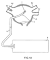
本発明は、人の組織において切除帯を作ることに関し、より具体的には、組織損傷を作るために用いられるトランスデューサアセンブリ(またはサブアセンブリ)に関する。図1Aは、上記に参照される関係する親出願に説明されるように、人の組織に切除帯を作るシステムの例示的実施形態の線図である。カテーテルデバイスCは、シースS内に収納される。カテーテルCの近位部分は、コンソールPに結合される。超音波トランスデューササブアセンブリTを備えている、カテーテルCの遠位部分は、心臓の中に、好ましくは経中隔で患者の肺静脈PVに隣接した左心房(LA)の中に導入される。トランスデューササブアセンブリTは、組織を切除するために超音波エネルギーを提供するように電圧を加えられる。コンソールPは、トランスデューササブアセンブリTへのエネルギー送達、ならびに切除経路を追跡するためにカテーテルCの遠位部分の動きを制御する。切除システムについてのさらなる詳細は、参照によって本明細書に援用された先の米国仮特許出願第61/254,997号に開示される。 The present invention relates to making an ablation zone in human tissue, and more particularly to a transducer assembly (or subassembly) used to create tissue damage. FIG. 1A is a diagram of an exemplary embodiment of a system for creating an ablation zone in human tissue, as described in the related parent application referenced above. The catheter device C is housed in the sheath S. The proximal portion of catheter C is coupled to console P. The distal portion of catheter C, comprising an ultrasonic transducer subassembly T, is introduced into the heart, preferably in the left atrium (LA) adjacent to the patient's pulmonary vein PV at the transseptal. The transducer subassembly T is energized to provide ultrasonic energy to ablate tissue. Console P controls the delivery of energy to transducer subassembly T, as well as the movement of the distal portion of catheter C to track the ablation path. Further details about the ablation system are disclosed in earlier US provisional patent application 61 / 254,997, incorporated herein by reference.
簡潔にするため、トランスデューササブセンブリは、本明細書において、組織を感知し切除するためのカテーテルの一実施形態に関して説明される。しかしながら、本発明のトランスデューサアセンブリは、医療分野および非医療分野の両方において任意の適切なデバイスと共に利用され得る。 For simplicity, the transducer subassembly is described herein with respect to one embodiment of a catheter for sensing and ablating tissue. However, the transducer assembly of the present invention can be utilized with any suitable device in both the medical and non-medical fields.
トランスデューササブアセンブリは、トランスデューサ要素を備え、同じトランスデューサ要素が(例えば、Aモードで)画像化し、切除するために用いられ得るように構成される。トランスデューサ要素はディスクの形状であり得るか、または他の形状がトランスデューサ要素のために用いられ得る。トンスデューササブアセンブリはまた、変換の効率を上げるためにトランスデューサ要素を効果的に冷却するように構成される。これは、遠位および近位のヒートシンクをトランスデューサ要素に取り付けることによって(例えば、接合、溶接、スナップフィッティングなどによって)達成され、それによって、トランスデューサ要素から熱を逃がすように伝える。さらに効率を上げるために、遠位ヒートシンクは音響的整合層を備え、近位ヒートシンクは音響的不整合のバッキング層を備えている。さらに、ヒートシンクの各々は、冷却物質(例えば、食塩水、水などの流体)が、トランスデューサ要素の近位表面および遠位表面(以下に「面」とも称される)に向けられ、トランスデューサ要素の面から熱を消散させることを可能にするように構成される。 The transducer subassembly includes a transducer element and is configured such that the same transducer element can be used to image and ablate (eg, in A mode). The transducer element can be in the form of a disk, or other shapes can be used for the transducer element. The transducer subassembly is also configured to effectively cool the transducer elements to increase the efficiency of the conversion. This is accomplished by attaching distal and proximal heat sinks to the transducer element (eg, by bonding, welding, snap fitting, etc.), thereby transferring heat away from the transducer element. For further efficiency, the distal heat sink has an acoustic matching layer and the proximal heat sink has an acoustically mismatched backing layer. In addition, each of the heat sinks has a cooling material (eg, a fluid such as saline, water, etc.) directed toward the proximal and distal surfaces (hereinafter also referred to as “faces”) of the transducer element, Configured to allow heat to be dissipated from the surface.
図1Bに示されるように、トランスデューササブアセンブリ3000は、カテーテル2000の遠位部分にまたはその近くに配置され、管状のジャケット3400内に収容される。カテーテル2000は、任意の適切なカテーテルであり得、少なくとも1つの内腔2100を備えている。トランスデューササブアセンブリ3000の構成要素は、図1Bの組立図、および図1Cの分解組立図で示される。トランスデューササブアセンブリ3000は、遠位面3102と近位面3104とを有するトランスデューサ要素3100を備えている。トランスデューササブアセンブリ3000は、ヒートシンクから熱を逃がすように伝えることによってトランスデューサ要素3000を冷却するように働くヒートシンクをさらに備えている。具体的には、トランスデューササブアセンブリ3000は、トランスデューサ要素3100の遠位面3102に接合される遠位ヒートシンク3300と、トランスデューサ要素3100の近位面3104に接合される近位ヒートシンク3200とを備えている。
As shown in FIG. 1B, the
ヒートシンクは、さらに、音響的整合および音響的反射によってトランスデューサ要素3000の動作効率を上げるように構成される。具体的にはそして下記にさらに詳細に説明されるように、遠位ヒートシンク3300は、音響的整合の層部分であって、すなわち、その部分の構成および厚さがトランスデューササブアセンブリ3000の前でトランスデューサ要素3100と任意の流体との間に1/4波長整合層を提供する、音響的整合の層部分を備えている。近位ヒートシンク3200は、音響的不整合の層部分であって、すなわち、その部分の構成がトランスデューサ要素3100の音響インピーダンスに音響的に不整合である、音響的不整合の層部分を備え、それによって、トランスデューサ要素3100から発する超音波をトランスデューサ要素3100の方に戻るように反射する。これらの部分は下記にさらに十分に説明される。
The heat sink is further configured to increase the operating efficiency of the
トランスデューササブアセンブリ3000はまた、ヒートシンク3200および3300を固定するベース3500を備え、トランスデューサ要素3100はそれらのヒートシンク間に接合される。トランスデューササブアセンブリ3000は、ヒートシンク3200および3300の各々に接合される1つ以上の電気ケーブル3600を用いて電力を供給される。これらの電気ケーブル3600は、図1Bおよび図1Cに示されるように、一対の撚線を介して例示として提供される。理解されるように、これらの電気ケーブルはまた、同軸線または分離(separate)非撚線であり得る。ヒートシンク3200および3300は、ヒートシンク3200および3300を電気ケーブル3600に電気的に結合する電気アタッチメント(図示されていない)を備え、それによって、トランスデューサ要素3100に電力を供給する。トランスデューサ要素3100は、トランスデューサ要素3100の面の上に電気的エネルギーを分配するために、遠位面および近位面に電極プレーティングを備えている。
The
本明細書に開示されるように、トランスデューサ要素3100は、単一のトランスデューサ要素を備えている。しかしながら、当業者は、この単一の要素がより小さいサブ要素から構成され得ることを理解する。トランスデューサは、心臓の心房の中に経費的に導入されるように構成されるカテーテルの中にフィットする適切なサイズである。例えば、一実施形態において、トランスデューサの直径は、0.2インチ未満であり、好ましくは0.15インチである。
As disclosed herein, the
さらに、トランスデューサ要素は、様々な外形、ならびに様々な音響的活性および不活性の部分を備え得る。そのようなトランスデューサ要素の特性は、次いで、作られた切除損傷の形状などのトランスデューサの画像化特性および切除特性に影響を与える。様々な形状およびサイズのトランスデューサ要素(サブ要素)を用いるというこれらの概念は、下記にさらに説明される。 In addition, the transducer elements can have various contours and various acoustically active and inactive portions. The characteristics of such transducer elements then affect the imaging and ablation characteristics of the transducer, such as the shape of the created ablation lesion. These concepts of using transducer elements (sub-elements) of various shapes and sizes are further explained below.
例えば、図1Bおよび図1Cに示される実施形態において、トランスデューサ要素3100は、平坦な円形のディスクであって、その近位面および遠位面から超音波エネルギーを送信する、ディスクである。トランスデューサ要素3100は、レンズの効果を達成するか、または、アポディゼーション(すなわち、トランスデューサ要素3100の表面の一部分もしくは複数の部分の振動を選択可能に減少させること)と、超音波ビームの伝達の管理とを支援するために、代わりに凹面もしくは凸面のいずれかなどのより複雑な外形を有し得る。
For example, in the embodiment shown in FIGS. 1B and 1C, the
他の例示的なトランスデューサは、図2A〜図2Dに示される。例えば、図2Aおよび図2Bに示されるように、トランスデューサ3100aおよび3100bは少なくとも1つの音響的不活性の部分4200を含み、トランスデューサ表面の残りは音響的活性の部分を備えている。これらの実施形態において、音響的不活性の部分4200は、トランスデューサが電圧を加えられたときエネルギービームを放出しないか、または代わりに、非常に低い(実質的に0)エネルギーを有するエネルギービームを放出し得る。音響的不活性の部分4200は、いくつかの機能を有する。例えば、そのようなトランスデューサを用いて組織を切除することによって生成される損傷の形状は、音響的活性の切除部分の形状に対応し得る。例えば、図1Bおよび図1Cに示される円形の実施形態において、損傷の形状は涙滴形状である。しかしながら、図2Aに示される環状の実施形態において、損傷の形状はおおよそ歯形であるかまたは鈍い涙滴形である。これは、図2Aにおける音響的不活性の部分4200が組織の対応する中心部分において、引き延ばされた切除を妨げるからである。組織の引き延ばされた切除がより深い切除を作るので、音響的不活性の部分4200の存在は、中心部分において切除が組織の中により深く到達することを妨げる。損傷は、従って、図2Aの例示的損傷形状Lによって示めされるように、涙形よりはむしろ、おおよそ歯形または鈍い涙滴形である。
Other exemplary transducers are shown in FIGS. 2A-2D. For example, as shown in FIGS. 2A and 2B,
作られる切除損傷の形状に影響を与える他に、音響的不活性の部分4200はさらに、示される任意の実施形態において、トランスデューサ要素3100aおよび3100bの温度調節を助ける、すなわちトランスデューサ要素が熱くなり過ぎるのを防ぐことを助けるように機能を果たす。
In addition to affecting the shape of the ablation lesion that is created, the acoustically
音響的不活性の部分は、様々な方法で作られ得る。一実施形態において、音響的不活性の部分4200は、トランスデューサ要素の音響的活性の領域の境界によって規定される穴または間隙である。そのような実施形態において、オプションの冷却剤源は、トランスデューサ要素の温度をさらに冷却し調節するために、トランスデューサ要素によって規定される穴または間隙に結合され得る(冷却流体の場合、冷却流体は穴または間隙を通って流れ得る)。
The acoustically inert portion can be made in a variety of ways. In one embodiment, the acoustically
別の実施形態において、音響的不活性の部分4200は、トランスデューサ要素の活性領域の特性とは異なる特性を有する材料組成を含み得る。例えば、音響的不活性の材料は、銅などの金属から作られ得、その金属はさらに、トランスデューサ要素から熱を逃がすように熱を引くかまたは伝えるように機能を果たす。代わりに、音響的不活性の部分4200は、トランスデューサ要素と同じ材料から作られ得るが、電極プレーティングが電気アタッチメントから取り外されるかまたは切断される。音響的不活性の部分4200は、トランスデューサ要素の全厚さに沿って配置され得るか、または代わりにトランスデューサ要素の全厚さより少ない厚さを有するトランスデューサ要素にある材料の層かもしくはトランスデューサ要素内の材料の層であり得る。
In another embodiment, the acoustically
例えば、図2Aに示されるように、トランスデューサ要素3100aはドーナツ形のトランスデューサであり、ドーナツ形のトランスデューサはそうでなければ円形のディスク形のトランスデューサ要素の中心部分において穴(または音響的不活性の部分)4200を含む。この実施形態のトランスデューサ要素3100aは、円形の外形を有するが、代わりに楕円形、図2Bに示されるような多角形、または任意の他の適切な形状であり得る。トランスデューサ要素3100aは、単一の円形で音響的不活性の部分4200を含むが、代わりに、図2Bに示されるように、任意の適切な外形の任意の適切な数の音響的不活性の部分4200を含み得る。音響的不活性の部分の例示的外形は、円形、正方形、長方形、楕円形、多角形、または任意の他の形状の領域を含む。トランスデューサ要素から放出される全エネルギーは、トランスデューサ要素の音響的活性の表面積に関係する。従って音響的活性の部分(単数、複数)4200のサイズおよび場所は、トランスデューサ要素における発熱性を十分に減少させ得、一方、トランスデューサ要素ができるだけ多くの出力エネルギーまたは所望の出力エネルギーを提供することを可能にする。
For example, as shown in FIG. 2A,
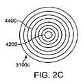
本明細書において開示されるように、トランスデューサ要素は、オプションで2つ以上の周波数で動作するように構成され得る。このことは、複数周波数の切除のためまたは診断と同時の切除のためにトランスデューサ要素が用いられることを可能にする。例えば、そのような複数周波数トランスデューサ要素は、標的組織を識別するために組織の一部分を画像化するのに用いられる第1の周波数範囲を用いて第1の出力レベルで断続的に動作させられ得、標的組織を切除するために用いられる第2の周波数範囲を用いて第2の出力レベルで動作させられ得る。一実施形態において、画像化周波数は、約5MHz〜30MHzの範囲であり、切除周波数は、好ましくは5MHz〜25MHzの範囲であり、より好ましくは8MHz〜20MHzの範囲であり、さらにより好ましくは10MHz〜18MHzの範囲である。これらの構成を達成するトランスデューサは、例示として、環状のトランスデューサまたはグリッドアレイであると示される。 As disclosed herein, the transducer element may optionally be configured to operate at more than one frequency. This allows the transducer element to be used for multiple frequency ablation or for simultaneous ablation with diagnosis. For example, such a multi-frequency transducer element may be operated intermittently at a first power level using a first frequency range that is used to image a portion of tissue to identify target tissue. And can be operated at a second power level using a second frequency range used to ablate the target tissue. In one embodiment, the imaging frequency is in the range of about 5 MHz to 30 MHz, and the ablation frequency is preferably in the range of 5 MHz to 25 MHz, more preferably in the range of 8 MHz to 20 MHz, and even more preferably from 10 MHz. The range is 18 MHz. Transducers that achieve these configurations are illustratively shown to be annular transducers or grid arrays.
図2Cおよび図2Dに示されるように、トランスデューサ要素3100cおよび3100dは、2つ以上の周波数で送信する能力があるように構成される。具体的には、図2Cに示されるように、トランスデューサ要素3100cは、複数の環状トランスデューサ部分4400を含む。複数の環状トランスデューサ部分は、複数の同心のリングであるが、代わりに、楕円形または多角形などの任意の適切な外形を有する任意の適切な構成を有し得る。オプションで、トランスデューサ要素3100cは、トランスデューサ3100cの中心部分などの1つ以上の音響的不活性の部分4200を含む。複数の環状トランスデューサ部分4400は、少なくとも、第1の環状部分と第2の環状部分とを含む。第1の環状部分は第2の環状部分の材料特性とは異なる材料特性を有し得、その結果、第1の環状部分は第2の環状部分によって放出される第2のエネルギービームとは異なる第1のエネルギービームを放出する。さらに第1の環状部分は、第2の環状部分とは異なる周波数、電圧、デューティサイクル、出力で、かつ/または異なる長さの時間で電圧を加えられ得る。代わりに、第1の環状部分は、第2の環状部分とは異なるモードで動作させられ得る。例えば、第1の環状部分は切除モードなどの療法モードで動作させられ得、療法モードは組織を加熱するのに十分な超音波エネルギーのパルスを送達する。第2の環状部分は、Aモードなどの画像化モードで動作させられ得、画像化モードは短い継続時間の超音波のパルスを送達し、短い継続時間の超音波のパルスは、概して組織の加熱に十分ではないが、超音波送達システムにおいてかつ超音波送達システムの周りにおいて標的組織および/または環境の特性を検出するように機能を果たす。第1の環状部分は、第2の環状部分の電気アタッチメントとは別個の電気アタッチメントをさらに含み得る。
As shown in FIGS. 2C and 2D,
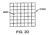
図2Dに示される複数周波数トランスデューサ要素の別の実施形態において、トランスデューサ要素3100dはトランスデューサ部分4600のグリッドを含む。トランスデューサ部分4600のグリッドは、円形、長方形、楕円形、多角形、または任意の他の適切な外形などの任意の適切な外形を有する。この変種におけるトランスデューサ要素3100dは、音響的に不活性である1つ以上のトランスデューサ部分をさらに含み得る。トランスデューサ部分4600のグリッドは、少なくとも、第1のトランスデューサ部分と、第2のトランスデューサ部分とを含む。第1のトランスデューサ部分および第2のトランスデューサ部分は、材料特性一式を有する単一のトランスデューサの複数の部分である。第1のトランスデューサ部分は、第2のトランスデューサ部分とは異なる周波数、電圧、デューティサイクル、出力で、かつ/または異なる長さの時間で電圧を加えられる。さらに、第1のトランスデューサ部分は、第2のトランスデューサ部分とは異なるモードで動作させられ得る。例えば、上記の説明と同様に、第1のトランスデューサ部分は切除モードなどの療法モードで動作し得、一方、第2のトランスデューサ部分はAモードなどの画像化モードで動作し得る。第1のトランスデューサ部分は、第2のトランスデューサ部分の電気アタッチメントとは別個の電気アタッチメントをさらに含み得る。例えば、第1のトランスデューサ部分はトランスデューサ要素3100dの中心の方に位置を定められ得、第2のトランスデューサ部分はトランスデューサ要素3100dの外側部分の方に位置を定められ得る。さらに、第2のトランスデューサ部分は電圧を加えられ得、一方、第1のトランスデューサ部分は不活性のままである。他の実施形態において、第1のトランスシューサ部分は第2のトランスデュサーサ部分の材料特性とは異なる材料特性を有し、その結果、第1のトランスデューサ部分は第2のトランスデューサ部分によって放出される第2のエネルギービームとは異なる第1のエネルギービームを放出する。そのような実施形態において、第1のトランスデューサ部分はまた、第2のトランスデューサ部分とは異なる周波数、電圧、デューティサイクル、出力で、かつ/または異なる長さの時間で電圧を加えられ得る。
In another embodiment of the multi-frequency transducer element shown in FIG. 2D,
ここでヒートシンク3200および3300に転じると、図3は、近位ヒートシンク3200を示す。この実施形態において、近位ヒートシンク3200は、接合部分3210と、接合部分3210に概ね直交の脚3220を形成する実質的に湾曲した部分とを備えている。近位ヒートシンクは、少なくとも1つの電気アタッチメント3230をさらに備えている。同様に、遠位ヒートシンクは、電気アタッチメント3330を備えている(図4に示される)。電線3600は、電気アタッチメント3230および3330に接続される。電気リード線がクリスタルの向かい合う面に接続される、トランスデューサクリスタルの従来の電気アタッチメントとは異なり、開示される配置は、「ホットスポット」を除去し、結果としてクリスタルの表面全体に均一の電気出力密度をもたらす。さらにこのことは、結果としてより容易な構造または製造工程をもたらす。
Turning now to
接合部分3210は、エポキシなどの適切な接合材料でトランスデューサ要素3100の近位面に接合され、接合層を形成する。この実施形態において接合部分3210が実質的に平らであるように示されているが、当業者は、接合部分3210が本明細書に説明される機能性をなおも維持して凹面部分などの任意の適切な構成であり得ることを理解する。実質的に湾曲した部分3220は、脚、またはトランスデューサ要素3100から近位に突き出る要素を備えている。さらに、湾曲部分3220は、流体が湾曲部分を通って流れることを可能にし、また流体がトランスデューサ要素3100の近位面を囲み冷却することを可能にするような方法で構成される。湾曲部分内に収容され得る流体は、効果的なヒートシンクを有することと画像性能を劣化させる音反響を最小にすることとの適切なバランスを達成する任意の適切な流体であり得る。近位ヒートシンク3200は、適切な厚さの銅などの適切な材料から形成される。このヒートシンクのための材料の厚さは、銅ヒートシンクに対して好ましくは0.0001インチ〜0.01インチの範囲である。
近位ヒートシンク3200は、トランスデューサ要素3100から熱を逃がすように伝えかつ消散させることによってトランスデューサの近位面を冷却するように働く。トランスデューサ要素3100からの熱は、接合部分3210によって吸収され、湾曲部分3220に伝えられ、そこで熱が循環流体の中に消散される。この消散は、トランスデューサ要素3100の近位面にいくらかの冷却を提供する。さらに、湾曲部分3220は、流体がトランスデューサ要素3100の近位面を囲み冷却することを可能にするように構成される。例えば、図3に示されるように、湾曲部分3220は、トランスデューサ要素3100の後ろに1つ以上のポケットを提供し、そのポケットにおいて流体は、トランスデューサ要素3100ならびにトランスデューサ要素3100の近位面から熱を消散させる近位ヒードシンク3200に流れ、それらの両方を冷却するように導入され得る。
上記に説明されるように、熱を消散させる他に近位ヒートシンク3200は、トランスデューサ要素3100においてホットスポットを減少させるヒートスプレッダとしても働き、それによって、トランスデューサ3100の全面にわたって熱を保持する。この熱の広がりがないと、トランスデューサ要素3100の中心は、トランスデューサ要素3100の残部より実質的に熱い。
As explained above, in addition to dissipating heat, the
接合部分3210は、トランスデューサ要素3100から伝導される反射エネルギーの量を最大にするように構成され得る。ヒートシンク用途に適している多くの金属は、PTZとあまり異なっていない音響インピーダンスを有するので、PTZとヒートシンク自体との間の境界は、あまり効果的な反射界面を提供しない。しかしながら、ヒートシールドにすぐの近位の別の材料は、それが効率的な音響反射器を提供するように選択され得る。例えば、空気は、水のように優れた音響不整合を提供するので、良好な反射器としてふるまう。水は空気ほど非常に効果的な反射器ではないとしても、水はまた熱導体としてふるまうので、水は好まれる。空気がトランスデューサアセンブリの周りの冷却流体の流れを妨げないならば、空気が用いられ得る。これを達成するために、3210の接合部分は、2つの金属層の間に空気の第3の薄い層を捕捉する2つの金属層から組み立てられる。代わりに、音響的に吸収する媒体を提供して残響を最小にし、画像化性能をさらに最適化するために、バッキング材料が近位ヒートシンク3200の近位に位置を定められ得る。そのようなバッキング材料は、オプションで、エポキシ、金属粒子、タングステンなどの組み合わせから作られ得る。
さらにまたは代わりに、トランスデューサ要素3100またはトランスデューササブアセンブリ3000は、三脚型構造(図示されていない)で配置され得、その結果、トランスデューサ要素3100の近位表面は三脚の中に面する。この構成においてトランスデューサ要素3100と三脚ベースとの間の空間にポケットが生ずる。このポケットは、同じ2つの面の目的を有する代替のバッキングとして働く。第1に、バッキングは、音響的に不整合であり、それによって、トランスデューサ要素3100から生ずる超音波を反射する。第2に、流体(例えば、食塩水または水)がトランスデューサアセンブリ3000の中に導入されると、ポケットはまた、流体がトランスデューサ要素3100と接触するようになることを可能にし、それによって、追加の冷却を提供する。
Additionally or alternatively, the
代わりに、妥当な熱伝導を有する別の適切な音響的に不整合の材料が、流体の代わりに用いられ得る。そのような材料は、例えばスチールウールまたは封入空気(entrapped air)を有する多孔性金属などの、閉じ込められた空気(trapped air)を有する金属を含む。例えば、PZTの背面は、多孔性金属のポケットが後ろに取り付けられている全背面を備えている薄いヒートスプレッダを備え得る。別の例として、PZTの中心は、ヒートシンクの一部として熱を伝える中心ポストを提供することによってさらに冷却され得、空気の環状リングが接合部分3210の後ろに閉じ込められることを可能にし得る。
Alternatively, another suitable acoustically mismatched material with reasonable heat conduction can be used in place of the fluid. Such materials include metals with trapped air, such as, for example, steel wool or porous metals with encapsulated air. For example, the back of the PZT may comprise a thin heat spreader with a full back with a porous metal pocket attached to the back. As another example, the center of the PZT may be further cooled by providing a central post that conducts heat as part of the heat sink, allowing an annular ring of air to be confined behind the
上記に言及されるように、熱を分配しトランスデューサ要素3100の遠位面を冷却する(ヒートスプレッダとしても働く)遠位ヒートシンク3300によって、追加の冷却が提供され得る。図4に示されるように、遠位ヒートシンク3300はまた、接合部分3310と、平らな部分3310に直交の実質的に湾曲した部分3320とを備えている。遠位ヒートシンクは、少なくとも1つの電気アタッチメント3330をさらに備えている。遠位ヒートシンク3300は、接合部分3310がトランスデューサ要素3100の遠位面に接合されるように構成される。実質的に湾曲した部分3320は、トランスデューサ要素3100から近位に突き出る要素または脚を備えている。従って、遠位ヒートシンク3300の湾曲部分3320は、近位ヒートシンク3200の湾曲部分3220に隣接している。上記に言及されるように、接合部分3310は、さらに、トランスデューサ要素3100のための音響的接合層として働くように構成される。熱伝導性でもある音響的整合構成を提供するために、接合部分3310はアルミニウムなどの適切な材料から作られ、他の適切な材料は、所望の周波数で厚さが1/4波長であるように、0.026インチ〜0.00026インチの範囲の適切な厚さで、グラファイト、金属充填のグラファイトもしくはセラミック、またはグラファイトと銅またはタングステンとの混合物を含む。接合部分3310は、エポキシなどの適切な接合材料でトランスデューサ要素3100の遠位面に接合され、接合層を形成する。
As mentioned above, additional cooling may be provided by a
さらにそしてオプションで、接合部分3310は、音響インピーダンス整合を高めるために適切な薄さの層に適用されるエポキシによって充填され得る目打ちまたは穴3315を備えている。遠位整合層における目打ちは、多くの方法で達成され得る。目打ち構造は、後にエポキシ材料で充填される開放空間を含む金属マトリックスの組み合わせから作られる。例えば、金属マトリックスはワイヤグリッドであり得る。代わりに、目打ち構造はエポキシ膜のマトリックスであり得、穴はアルミニウムなどの金属で充填され得る。さらに、エポキシと金属との混合率は、音響インピーダンス整合を高めるように構成される。音響インピーダンスは、2つの複合材料の音響インピーダンスおよび混合率によって決定される。例えば、アルミニウムおよびEPO−TEK(登録商標)377(Epoxy Technology,Inc.,Billerica,MA)を用いて、適切な率は35%〜60%のエポキシの容積分率であり、良好な音響インピーダンス整合は40%〜50%のエポキシの容積分率で達成され、理想的な整合は約41%である。さらに、目打ちまたは穴3315は、超音波ビームの波長と比較して十分に小さい直径を有し、それによって、接合部分3310は、トランスデューサ要素3100から生ずる伝搬波(propagating wave)と同質であるように見えることを可能にする。
Additionally and optionally, the
音響インピーダンス整合を達成するために目打ちまたは穴を有する接合部分3310を用いる構造と同様に、トランスデューサクリスタルの近位表面における接合部分3210はまた、音響インピーダンス不整合を達成するために用いられる材料において目打ちまたは穴を用いることから利益を受け得る。そのような材料は、銅、タングステンなどを含み得る。代わりに、エポキシ層に撒かれた金属粒子を有するエポキシ層および穴または目打ちの分布は、音響インピーダンスを提供することと同じ目的を達成し得る。
Similar to structures that use
(銀などの金属粒子を有する)非伝導性および伝導性のエポキシの両方とも、近位接合層または遠位接合層のいずれかを形成するために用いられ得る。一実施形態において、エポキシは例示として低粘性の非伝導性エポキシ(例えば、EPO−TEK(登録商標)377)である。エポキシは、音響インピーダンス整合に対するエポキシの影響を最小にするために、適切な薄さの層に適用され、一方、トランスデューサ3100を冷却するために熱伝導性を最大にする。さらに、接合層はまた、ヒートシンク3310および3210をトランスデューサ3100に電気的に接続するように構成される。これは、トランスデューサ3100面および整合部分3310および3210を粗くするように構成することによって、伝導性エポキシを用いることなくうまく達成される。その後、トランスデューサ要素3100の遠位面および近位面は、電気的非伝導性エポキシを有する、遠位面および近位面に関係のあるヒートシンクに接合される。各接合層は、トランスデューサ3100の表面あらさがヒートシンク3310および3210の表面あらさに電気的に接触することを可能にするほど十分な薄さである。これは、トランスデューサ要素3100の粗い表面がその表面に関係のあるヒートシンクに直接に電気的接触することを可能にし、それによって(熱と共に劣化し得る)電気的伝導性エポキシを用いることを不要にする。従って、電気的伝導性は、エポキシを介するよりはむしろ、トランスデューサ要素3100の粗い表面とヒートシンクとの間の接触点を経由して行われる。
Both non-conductive and conductive epoxies (with metal particles such as silver) can be used to form either the proximal or distal bonding layer. In one embodiment, the epoxy is illustratively a low viscosity non-conductive epoxy (eg, EPO-TEK® 377). Epoxy is applied to an appropriately thin layer to minimize the effect of epoxy on acoustic impedance matching, while maximizing thermal conductivity to cool
さらにそしてオプションで、パリレンまたは任意のそのようなコーティングは、追加の整合層としてふるまうために遠位ヒートシンク3300の接合部分3310に配置される。コーティングの1つの結果は、従って、トランスデューサ要素3100伝導性の効率を上げるためかつ広帯域幅性能をさらに最適化するために第2の音響整合層を生成することであり得る。このパリレンコートの厚さは、標的超音波波長の1/4である。オプションで、ヒートシンク3200および3300の両方は、電気的絶縁を提供するために、パリレンまたは任意のそのような適切なコーティングによって被覆される。さらに、ヒートシンクは、電気的絶縁を提供するために陽極処理され、一方、熱伝導性を最大にする。トランスデューササブアセンブリ3000は、図5に示されるように管状ジャケット3400内に位置を定められる。管状ジャケット3400は、近位端および遠位端を有する空洞の円筒である。トランスデューササブアセンブリ3000は、管状ジャケットの遠位端がトランスデューササブアセンブリ3000の遠位端を越えて適切な距離、例えば1mm〜5mm突き出るように管状ジャケット3400の中に配置される。管状ジャケット3400の遠位端は、遠位開口部3410と、遠位開口部の近くに位置を定められる流体出口ポート3420とを備えている。トランスデューサ要素3100の冷却は、食塩水、水、または任意の生理的適合の流体もしくはゲルなどの冷却流体もしくはゲルを管状ジャケット3400の近位端の中に導入することによって達成され得る。冷却流体は、トランスデューサ要素3100の温度に対してより低い温度を有する。冷却流体は、ヒートシンク3200および3300の湾曲部分3220および3320に沿って接合部分3210および3310の両方を越えて流れ、遠位開口部3410、流体出口ポート3420、またはこれらの任意の組み合わせを通って出ていく。オプションで出口ポート3420は、グレーティング、スクリーン、穴、水抜き穴、浸出構造(weeping structure)、または任意の数の適切なアパーチャの形式であり得る。
Additionally and optionally, parylene or any such coating is placed on the
さらに、トランスデューササブアセンブリ3000において説明される任意の金属構成要素またはそのすべては、金などの適切な生体適合材料のプレーティングが備え付けられる。そのようなプレーティングは、トランスデューサアセンブリが組み立てられる前に個々の構成要素に備え付けられる。
Further, any or all of the metal components described in
例示的実施形態において、冷却流体または冷却ゲルの温度は、冷却流体または冷却ゲルがトランスデューサ要素3100およびオプションで標的組織を冷却するほど十分に低い。この実施形態において、流体またはゲルの温度は、おおよそ―5と体温との間である。第2の実施形態において、冷却流体または冷却ゲルの温度は、冷却流体または冷却ゲルがトランスデューサ要素3100を冷却するが、標的組織を冷却しないで、実際は標的組織を暖め得るような温度範囲内である。流体またはゲルは、代わりにトランスデューサ要素3100を十分に冷却する、室温を含む任意の適切な温度であり得る。
In the exemplary embodiment, the temperature of the cooling fluid or gel is sufficiently low that the cooling fluid or gel cools the
上記に説明される本発明は、小さい方のトランスデューサアセンブリを冷えた状態に保つという利点を有する。前に言及されたように、トランスデューサの直径は、カテーテルの先端の中にフィットするほど十分に小さい(0.2インチ未満、理想的には0.15インチ未満)が、組織損傷を作るのに十分に高い出力密度レベルを生成する(約50ワット/cm2〜2500ワット/cm2)。本発明は、組織損傷を効率的に作るためにトランスデューサアセンブリを冷えた状態に保つ。 The invention described above has the advantage of keeping the smaller transducer assembly cool. As previously mentioned, the transducer diameter is small enough to fit within the tip of the catheter (less than 0.2 inches, ideally less than 0.15 inches) to create tissue damage. Produces sufficiently high power density levels (approximately 50 watts / cm 2 to 2500 watts / cm 2 ). The present invention keeps the transducer assembly cool to efficiently create tissue damage.
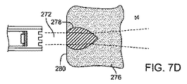
本出願人らは、ここで損傷の形成を説明することに転じる。組織との超音波ビームの相互作用は、図6に説明される。組織276は、視準長L内の超音波ビーム272に提示される。組織276の前面280は、カテーテル2000の遠位先端2110から距離d(282)だけ離れている。超音波ビーム272は組織276を通って移動するので、超音波ビーム272のエネルギーは組織276によって吸収されかつ散乱させられ、超音波エネルギーのほとんどは熱エネルギーに変換させられる。この熱エネルギーは、周囲の組織より高い温度に組織を加熱する。結果は、長く延びた涙滴の典型的な形状を有する加熱帯278である。帯278の直径D1は、組織表面280におけるトランスデューサアパーチャ直径Dより小さく、さらに、組織276の外側層276は、実質的に損傷されないままである。これは、組織表面280を通過して流れる周囲の流体によって提供される熱冷却のためである。組織276の外側層は、組織表面280が冷却される量に従って、かつ/または超音波送達システムの特性(トランスデューサ要素3100、超音波ビーム272、超音波エネルギーおよび周波数を含む)に従って、多かれ少なかれそのまま残され得るかまたは実質的に損傷されないままであり得る。切除帯278に堆積されたエネルギーは、心臓内面がもとのままでありかつ/または焦がされないように、組織と相互に作用する。超音波ビーム272は組織276の中により深く進むので、熱冷却は、周囲の組織によって提供され、表面上の熱冷却ほど効率的ではない。結果として、周囲の組織の伝熱特性ならびにビーム272からの超音波エネルギーの継続する入力によって決定されるように、切除帯278がD1より大きい直径D2を有する。この超音波−組織の相互作用中、超音波エネルギーは組織276によって吸収され、組織の中にさらに進む利用可能な超音波エネルギーがより少なくなる。従って対応するより小さい直径の加熱帯は組織276において発達させられ、全体的な結果として、加熱切除帯278の形成となり、加熱切除帯278は組織276の中に深さ288に限定された長く延びた涙滴の形状である。
Applicants now turn to describing the formation of damage. The interaction of the ultrasonic beam with the tissue is illustrated in FIG. The
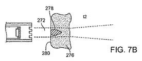
切除帯(切除帯のサイズおよび他の特性を含む)の形成は、図7A〜図7Dに示されるように時間に依存し、図7A〜図7Dは、時間t1、t2、t3およびt4のそれぞれにおける損傷の形成を示す。音ビーム272が最初に時間t1において組織276の前面280突き当ると、熱が作られ、熱は損傷278を形成し始める(図7A)。時間がt2およびt3に経過すると(図7Bおよび7C)、切除帯278は直径および深さにおいて成長し続ける。このt1からt3への時間順序は、超音波エネルギー密度に従って、わずか約1秒〜5秒、または好ましくは約3秒〜5秒を要する。超音波ビーム272の入射が時間t3を越えて継続されると、切除損傷278は、直径および長さにおいてわずかに成長し、次いで、エネルギーの超音波形態から熱形態へのエネルギー移動において達成され、周囲の組織の中への熱エネルギーの消散によって平衡が保たれる定常状態により、成長が止まる。図7Dに示される例は、超音波ビーム272に対しておおよそ30秒の曝露t4後の損傷を示す。従って、損傷は、サイズにおいて自然の限度に達し、無限に成長するのではない。
The formation of the ablation zone (including the size of the ablation zone and other characteristics) is time dependent as shown in FIGS. 7A-7D, which are shown at times t1, t2, t3 and t4, respectively. Shows the formation of damage in When the
超音波ビーム272によって形成される損傷また切除帯278の形状は、超音波ビーム272、(材料、外形、電圧を加えられかつ/または電圧を加えられないトランスデューサ要素3100の部分などを含む)トランスデューサ要素3100、存在する任意の整合層および/またはバッキング、(周波数、電圧、デューティサイクル、信号の長さおよび形状などを含む)電気エネルギー源からの電気信号、およびエネルギー送達の継続時間などの要因に依存する。標的組織の特性は、伝熱特性と、超音波の吸収および減衰と、標的組織および周囲組織の後方散乱特性とを含む。切除帯278のサイズおよび特性はまた、所望の超音波ビームを作るためにトランスデューサ要素3100に印加される周波数および電圧に依存する。
The shape of the lesion or
上記に言及されるように、トランスデューサ要素の形状および構造などの特性は、トランスデューサ要素によって作られる切除損傷に影響を与える。図7A〜図7Dに示される特定の例の損傷は、例えば、円形ディスクを備えているトランスデューサ要素3100によって生成されるような涙形の損傷である。切除形状の第2の変種は図8に示され、図8において切除帯278’はより短い深さ288’を有する。この変種において、損傷278’は、図6の切除帯278よりも鈍い形状を有する。この第2の変種の1つのあり得る損傷外形は、図8に示されるように歯形の外形であり得るが、但し、外形は代わりに、鈍い涙形、円形、または楕円形を有し得る。図8に示されるように、(図6における帯278に類似した)帯278’は、組織表面280を通過して流れる周囲の流体によって提供される熱冷却のために、組織表面280においてビーム272’の直径Dより小さい直径D1を有する。損傷外形におけるこの変種は、トランスデューサ3100aによって生成され、トランスデューサ3100aは、その中心に位置を定められる音響的不活性部分4200を有する、すなわち、図6に示される超音波ビーム272より広く平らな輪郭を有して概してより多く放散させられる超音波ビーム272’を放出するドーナツ形トランスデューサである。図8に示されるように、そのようなドーナツ形トランスデューサから放出される超音波ビーム272’は、(図8において点線によって断面で示されるような)エネルギービームの正中線に沿って、減少した頂点強度を有する。この超音波−組織の相互作用によって、エネルギービームの正中線に沿う減少した頂点強度は、組織によって吸収され、組織の中にさらに進むために利用され得るエネルギーが益々少なくなり、それによって結果として、第1の変種と比較してより鈍い損傷をもたらす。
As mentioned above, characteristics such as the shape and structure of the transducer element affect the ablation damage created by the transducer element. The particular example of damage shown in FIGS. 7A-7D is, for example, a tear-shaped damage as generated by a
超音波エネルギー密度は、切除が行われる速度を決定する。トランスデューサ要素3100によって送達される音響出力は、ビーム幅の断面積によって割られ、単位時間当たりのエネルギー密度を決定する。本実施形態において、有効音響出力は、好ましくは0.5ワット〜25ワット、より好ましくは2ワット〜10ワット、そしてさらにより好ましくは2ワット〜7ワットの範囲である。対応する出力密度は、おおよそ50ワット/cm2〜2500ワット/cm2の範囲である。これらの出力密度は、切除帯において発達させられる。ビームが切除帯を越えて分散すると、エネルギー密度は露出時間に関わらず切除が行われないように降下する。
The ultrasonic energy density determines the rate at which ablation is performed. The acoustic power delivered by the
トランスデューササブアセンブリ3000は、さらにセンサ(図示されていない)に結合され得る。センサの1つの変種は温度センサである。温度センサは、周囲環境の温度、トランスデューサ要素3100の温度、および/または任意の他の要素または領域の温度を検出するように機能を果たす。センサはまた、冷却流体がトランスデューサを通過して流れると、冷却流体の温度を監視するためにも用いられ得る。温度センサは、熱電対であるが、代わりにサーミスタまたは赤外線温度センサなどの任意の適切な温度センサであり得る。オプションで、温度センサは、例えば近位面おいてトランスデューサに結合される。センサによって集められた温度情報は、療法中に連続的な切除エネルギーを組織276に送達することを管理し、標的組織および/または超音波送達システムの温度を管理するために用いられる。一実施形態において、センサは、トランスデューサ要素3100の外形と実質的に同一である外形を有し、その結果、センサによって診断される面積は、トランスデューサ要素3100によって治療される面積と実質的に同一である。代わりに、センサは、超音波エネルギーの送達を妨げることを最小にするためにより小さい外形を有するが、特定の場所のホットスポットである領域に位置を定められ得る。例えば、近位ヒートスプレッダ3200の中心に取り付けられる小さい熱電対は、トランスデューサアセンブリの最も熱いホットスポットの温度を監視する。温度センサについての追加の詳細は、上記に参照によって前に援用された出願に開示される。
The
代わりに、センサの第2の変種において、同じ超音波トランスデューサ要素3100は、センサとして働き、組織検出の目的のために用いられる。一方において、切除を達成するために、トランスデューサ要素3100は、エネルギー入力が周囲の組織による冷却によって提供される熱緩和を超えるように、十分なエネルギーの超音波ビームを生成し、組織に送達するために用いられる。超音波トランスデューサ要素3100に電圧加えるこのモードは、切除モードと称される。他方において、トランスデューサ要素3100は、概して組織の加熱に十分ではない、組織感知に最適化された超音波信号を利用することによって、組織を画像化するかまたは組織特性を検出するために用いられ得る。1つのそのような超音波画像化技術は、当該分野においてA−ModeまたはAmplitude Mode画像化と呼ばれる。トランスデューサ要素3100に電圧を加えるこのモードは、画像化モードと称される。画素化モードは、組織の切除によって提供される療法を指示する際に利用される。トランスデューサ要素3100は、間隙(すなわち、カテーテル2000の遠位先端から組織表面までの距離)、切除の標的とする組織の厚さ、切除組織の特性、入射ビーム角度、または、温度、厚さおよび切除深さなどの超音波送達システムの周りの組織および/または環境の任意の他の適切なパラメータもしくは特性を検出するために、画像化モードにおいて用いられ得る。これらおよび他の適用可能な特徴は、参照によって前に援用された開示に説明される。
Instead, in the second variant of the sensor, the same
さらにそしてオプションで、好ましい実施形態の超音波送達システムは、センサに結合されたプロセッサを含み、プロセッサは、センサによって得られた情報に基づいて電気アタッチメントおよび/または電気アタッチメントに送達された電気信号を制御する。プロセッサは、従来のプロセッサであり得るか、または代わりに所望の処理機能を行う任意の適切なデバイスであり得る。 Additionally and optionally, the ultrasound delivery system of the preferred embodiment includes a processor coupled to the sensor, the processor receiving an electrical attachment and / or an electrical signal delivered to the electrical attachment based on information obtained by the sensor. Control. The processor can be a conventional processor or can alternatively be any suitable device that performs the desired processing functions.
プロセッサは、カテーテルと組織との間の距離(すなわち、間隙距離)、切除の標的とする組織の厚さ、切除組織の特性、または任意の他の適切なパラメータまたは特性に関係する情報などの情報をセンサから受信する。この情報に基づいて、プロセッサは、電気アタッチメントを経由してトランスデューサ要素3100に送られる電気信号を修正することによって、トランスデューサ要素3100によって放出される超音波ビームを制御する。これは、周波数、電圧、デューティサイクル、パルスの長さ、および/または任意の他のパラメータを修正することを含み得る。プロセッサはまた、トランスデューサ要素のどの部分に電圧が加えられるかを制御することによって、かつ/またはトランスデューサ要素の様々な部分に電圧が加えられ得る場合の周波数、電圧、デューティサイクルなどを制御することによって、多要素トランスデューサにおいて超音波ビームを制御し得る。さらに、プロセッサは、さらに流体フローコントローラに結合され得る。プロセッサは、切除組織、未切除組織または標的組織、冷却流体の温度、組織および/もしくはエネルギー源の検出された特性、ならびに/または任意の他の適切な条件に基づいて流体フローを増加させるかまたは減少させるために、流体フローコントローラを制御し得る。さらにプロセッサは、所望の温度の動作範囲内にトランスデューサ要素3100を維持するために、流体フローコントローラを制御し得る。さらに組織に損傷線または損傷形状を作るためのトランスデューサの動きは、オペレータによるかまたはプロセッサ制御下の1つ以上のモータを介してのいずれかで制御され得る。
Information such as the distance between the catheter and the tissue (ie, the gap distance), the thickness of the tissue targeted for ablation, the characteristics of the ablated tissue, or information related to any other suitable parameter or characteristic Is received from the sensor. Based on this information, the processor controls the ultrasound beam emitted by the
超音波ビーム、および/または標的組織もしくはトランスデューサ要素3100の冷却を制御することによって、切除帯278の形状が制御され得る。例えば、切除帯の深さ288は、経壁または実質的に経壁の損傷が達成されるように制御され得る。さらに損傷の性質は、ビームの速度を制御することによって制御され得る。ビームが組織に沿って動く速度は、組織に堆積するエネルギーの量を決定する。従って、例えば、より遅い速度は、結果としてより長い滞留時間をもたらし、それによって、組織に転送されるエネルギーを増加させ、従ってより深い損傷を作る。さらに、プロセッサは、例えば外心房壁を越えるなど標的組織を越えて損傷を作る可能性を最小にするように機能を果たす。損傷および/または切除ウィンドウが心房の外壁を越えようとしていることまたは損傷の深さが所定の深さに達したかまたは所定の深さを越えたことをセンサが検出した場合、プロセッサは、発電機の電源を切りかつ/または電気信号をトランスデューサに送りかつ/またはビームを動かす。
By controlling the ultrasound beam and / or cooling of the target tissue or
さらにプロセッサは、トランスデューサと標的組織の表面との間の好ましい間隙距離を維持するように機能を果たし得る。間隙距離は、好ましくは2mm〜25mmであり、より好ましくは2mm〜20mmであり、さらにより好ましくは2mm〜15mmである。損傷および/または切除ウィンドウが心房の外壁を越えて延びようとしているかもしくは心房の外壁に到達していないこと、または損傷の深さが所定の深さに到達していないかもしくは所定の深さを越えたことをセンサが検出した場合、プロセッサは、エネルギー送達システムの位置を変え得る。例えばカテーテル2000が回転させられた場合、切除ウィンドウは、(円形の切除経路または楕円形の切除経路などの)切除経路を掃引し、円すい胴の断面を作る。しかしながら、切除ウィンドウが心房の壁に達していないことをセンサが決定した場合、プロセッサは、解剖におけるあり得る変動に対して調整するために、長くなった部材をZ軸に沿って前後に動かし得るか、または長くなった部材が動かされるべきであることを指示し得る。そのような一実施形態において、オペレータは、カテーテル2000の位置を変え得るか、またはプロセッサはモータ駆動ユニットもしくはカテーテル2000の位置を変えるように機能を果たす他の制御ユニットに結合され得る。
Further, the processor may function to maintain a favorable gap distance between the transducer and the target tissue surface. The gap distance is preferably 2 mm to 25 mm, more preferably 2 mm to 20 mm, and even more preferably 2 mm to 15 mm. The injury and / or resection window is about to extend beyond the outer wall of the atrium or has not reached the outer wall of the atrium, or the depth of the injury has not reached the predetermined depth or has reached the predetermined depth If the sensor detects that it has been exceeded, the processor can change the position of the energy delivery system. For example, if the
上記トランスデューサ要素およびトランスデューササブアセンブリは切除カテーテルの関係において説明されたが、本明細書において説明されるトランスデューサ要素およびトランスデューササブアセンブリが超音波による組織を画像化しかつ/または組織を切除するように構成される任意のデバイスの一部として用いられ得る事は理解されるべきである。さらに上記のことは、本発明の好ましい実施形態の完全な説明であるが、様々な代案、修正および均等物が用いられ得る。従って、上記の説明は、本発明の範囲を限定することとして解されるべきではなく、本発明の範囲は添付の特許請求の範囲によって規定される。 Although the transducer elements and transducer subassemblies have been described in the context of an ablation catheter, the transducer elements and transducer subassemblies described herein are configured to image ultrasound tissue and / or ablate tissue. It should be understood that it can be used as part of any device. Furthermore, while the above is a complete description of the preferred embodiment of the present invention, various alternatives, modifications and equivalents may be used. Therefore, the above description should not be taken as limiting the scope of the invention, which is defined by the appended claims.
Claims (18)
該トランスデューサ要素の該遠位表面に取り付けられた第1のヒートシンクであって、該第1のヒートシンクは、第1の接合部分を備え、該第1の接合部分は、該トランスデューサの該遠位表面に接合され、該第1の接合部分は、材料を含み、該材料の組成および寸法が該トランスデューサ要素の該遠位表面に音響的整合層を提供する、第1のヒートシンクと、
該トランスデューサ要素の該近位表面に取り付けられた第2のヒートシンクであって、該第2のヒートシンクは、第2の接合部分と、第2の実質的に湾曲した部分とを備え、該第2の接合部分は、該トランスデューサの該近位表面に接合され、該第2の実質的に湾曲した部分は、該トランスデューサ要素から近位に突き出る脚を含むことによって、該トランスデューサ要素の該近位表面から熱を逃がすように伝え、該第2のヒートシンクは、該トランスデューサの該近位表面および該遠位表面に流体の流れを向けるように構成されている、第2のヒートシンクと、
該第1のヒートシンクおよび第2のヒートシンクに結合されたベースであって、該ベースは、該トランスデューサ要素の該近位表面および遠位表面を冷却するために該トランスデューサ要素を通過して流体が流れることを可能にするように構成されている、ベースと
を備え、
該第1のヒートシンクおよび該第2のヒートシンクは、該トランスデューサに電力を提供する、トランスデューサシステム。 A transducer element comprising a proximal surface and a distal surface;
A first heat sink attached to the distal surface of the transducer element, the first heat sink comprising a first joint, the first joint being the distal surface of the transducer; A first heat sink comprising a material, the composition and dimensions of the material providing an acoustic matching layer on the distal surface of the transducer element;
A second heat sink attached to the proximal surface of the transducer element, the second heat sink comprising a second joining portion and a second substantially curved portion; A joining portion of the transducer element is joined to the proximal surface of the transducer, and the second substantially curved portion includes a leg projecting proximally from the transducer element to thereby provide the proximal surface of the transducer element A second heat sink configured to direct fluid flow to the proximal surface and the distal surface of the transducer ;
A base coupled to the first heat sink and the second heat sink, wherein the base flows fluid through the transducer element to cool the proximal and distal surfaces of the transducer element; Comprising a base, configured to allow
The transducer system, wherein the first heat sink and the second heat sink provide power to the transducer.
Applications Claiming Priority (3)
| Application Number | Priority Date | Filing Date | Title |
|---|---|---|---|
| US11540308P | 2008-11-17 | 2008-11-17 | |
| US61/115,403 | 2008-11-17 | ||
| PCT/US2009/064850 WO2010057211A1 (en) | 2008-11-17 | 2009-11-17 | Systems and methods for ablating body tissue |
Related Child Applications (1)
| Application Number | Title | Priority Date | Filing Date |
|---|---|---|---|
| JP2014226653A Division JP2015027579A (en) | 2008-11-17 | 2014-11-07 | System and method for ablating body tissue |
Publications (3)
| Publication Number | Publication Date |
|---|---|
| JP2012509111A JP2012509111A (en) | 2012-04-19 |
| JP2012509111A5 JP2012509111A5 (en) | 2012-12-27 |
| JP5941281B2 true JP5941281B2 (en) | 2016-06-29 |
Family
ID=42170429
Family Applications (2)
| Application Number | Title | Priority Date | Filing Date |
|---|---|---|---|
| JP2011536608A Active JP5941281B2 (en) | 2008-11-17 | 2009-11-17 | System and method for ablating body tissue |
| JP2014226653A Pending JP2015027579A (en) | 2008-11-17 | 2014-11-07 | System and method for ablating body tissue |
Family Applications After (1)
| Application Number | Title | Priority Date | Filing Date |
|---|---|---|---|
| JP2014226653A Pending JP2015027579A (en) | 2008-11-17 | 2014-11-07 | System and method for ablating body tissue |
Country Status (7)
| Country | Link |
|---|---|
| US (2) | US9737323B2 (en) |
| EP (1) | EP2352559B1 (en) |
| JP (2) | JP5941281B2 (en) |
| AU (2) | AU2009313687B2 (en) |
| CA (1) | CA2742787C (en) |
| ES (1) | ES2447291T3 (en) |
| WO (1) | WO2010057211A1 (en) |
Families Citing this family (136)
| Publication number | Priority date | Publication date | Assignee | Title |
|---|---|---|---|---|
| US8241274B2 (en) | 2000-01-19 | 2012-08-14 | Medtronic, Inc. | Method for guiding a medical device |
| US8150519B2 (en) | 2002-04-08 | 2012-04-03 | Ardian, Inc. | Methods and apparatus for bilateral renal neuromodulation |
| US7617005B2 (en) | 2002-04-08 | 2009-11-10 | Ardian, Inc. | Methods and apparatus for thermally-induced renal neuromodulation |
| US20070084897A1 (en) | 2003-05-20 | 2007-04-19 | Shelton Frederick E Iv | Articulating surgical stapling instrument incorporating a two-piece e-beam firing mechanism |
| US9060770B2 (en) | 2003-05-20 | 2015-06-23 | Ethicon Endo-Surgery, Inc. | Robotically-driven surgical instrument with E-beam driver |
| US11890012B2 (en) | 2004-07-28 | 2024-02-06 | Cilag Gmbh International | Staple cartridge comprising cartridge body and attached support |
| US10159482B2 (en) | 2005-08-31 | 2018-12-25 | Ethicon Llc | Fastener cartridge assembly comprising a fixed anvil and different staple heights |
| US7669746B2 (en) | 2005-08-31 | 2010-03-02 | Ethicon Endo-Surgery, Inc. | Staple cartridges for forming staples having differing formed staple heights |
| US11246590B2 (en) | 2005-08-31 | 2022-02-15 | Cilag Gmbh International | Staple cartridge including staple drivers having different unfired heights |
| US8708213B2 (en) | 2006-01-31 | 2014-04-29 | Ethicon Endo-Surgery, Inc. | Surgical instrument having a feedback system |
| US8186555B2 (en) | 2006-01-31 | 2012-05-29 | Ethicon Endo-Surgery, Inc. | Motor-driven surgical cutting and fastening instrument with mechanical closure system |
| US11793518B2 (en) | 2006-01-31 | 2023-10-24 | Cilag Gmbh International | Powered surgical instruments with firing system lockout arrangements |
| US7845537B2 (en) | 2006-01-31 | 2010-12-07 | Ethicon Endo-Surgery, Inc. | Surgical instrument having recording capabilities |
| US20080039746A1 (en) | 2006-05-25 | 2008-02-14 | Medtronic, Inc. | Methods of using high intensity focused ultrasound to form an ablated tissue area containing a plurality of lesions |
| US8684253B2 (en) | 2007-01-10 | 2014-04-01 | Ethicon Endo-Surgery, Inc. | Surgical instrument with wireless communication between a control unit of a robotic system and remote sensor |
| US20080169332A1 (en) | 2007-01-11 | 2008-07-17 | Shelton Frederick E | Surgical stapling device with a curved cutting member |
| US11857181B2 (en) | 2007-06-04 | 2024-01-02 | Cilag Gmbh International | Robotically-controlled shaft based rotary drive systems for surgical instruments |
| US8931682B2 (en) | 2007-06-04 | 2015-01-13 | Ethicon Endo-Surgery, Inc. | Robotically-controlled shaft based rotary drive systems for surgical instruments |
| US11849941B2 (en) | 2007-06-29 | 2023-12-26 | Cilag Gmbh International | Staple cartridge having staple cavities extending at a transverse angle relative to a longitudinal cartridge axis |
| BRPI0901282A2 (en) | 2008-02-14 | 2009-11-17 | Ethicon Endo Surgery Inc | surgical cutting and fixation instrument with rf electrodes |
| US9386983B2 (en) | 2008-09-23 | 2016-07-12 | Ethicon Endo-Surgery, Llc | Robotically-controlled motorized surgical instrument |
| US8210411B2 (en) | 2008-09-23 | 2012-07-03 | Ethicon Endo-Surgery, Inc. | Motor-driven surgical cutting instrument |
| US9005230B2 (en) | 2008-09-23 | 2015-04-14 | Ethicon Endo-Surgery, Inc. | Motorized surgical instrument |
| US8608045B2 (en) | 2008-10-10 | 2013-12-17 | Ethicon Endo-Sugery, Inc. | Powered surgical cutting and stapling apparatus with manually retractable firing system |
| US9320523B2 (en) | 2012-03-28 | 2016-04-26 | Ethicon Endo-Surgery, Llc | Tissue thickness compensator comprising tissue ingrowth features |
| US11849952B2 (en) | 2010-09-30 | 2023-12-26 | Cilag Gmbh International | Staple cartridge comprising staples positioned within a compressible portion thereof |
| US9629814B2 (en) | 2010-09-30 | 2017-04-25 | Ethicon Endo-Surgery, Llc | Tissue thickness compensator configured to redistribute compressive forces |
| US10945731B2 (en) | 2010-09-30 | 2021-03-16 | Ethicon Llc | Tissue thickness compensator comprising controlled release and expansion |
| US10213198B2 (en) | 2010-09-30 | 2019-02-26 | Ethicon Llc | Actuator for releasing a tissue thickness compensator from a fastener cartridge |
| US11812965B2 (en) | 2010-09-30 | 2023-11-14 | Cilag Gmbh International | Layer of material for a surgical end effector |
| CA2834649C (en) | 2011-04-29 | 2021-02-16 | Ethicon Endo-Surgery, Inc. | Staple cartridge comprising staples positioned within a compressible portion thereof |
| US9072535B2 (en) | 2011-05-27 | 2015-07-07 | Ethicon Endo-Surgery, Inc. | Surgical stapling instruments with rotatable staple deployment arrangements |
| JP5926806B2 (en) | 2011-09-22 | 2016-05-25 | ザ・ジョージ・ワシントン・ユニバーシティThe George Washingtonuniversity | System and method for visualizing ablated tissue |
| EP2757933B1 (en) | 2011-09-22 | 2019-02-06 | The George Washington University | Systems for visualizing ablated tissue |
| CN104321024B (en) | 2012-03-28 | 2017-05-24 | 伊西康内外科公司 | Tissue thickness compensator comprising a plurality of layers |
| JP6105041B2 (en) | 2012-03-28 | 2017-03-29 | エシコン・エンド−サージェリィ・インコーポレイテッドEthicon Endo−Surgery,Inc. | Tissue thickness compensator containing capsules defining a low pressure environment |
| US9101358B2 (en) | 2012-06-15 | 2015-08-11 | Ethicon Endo-Surgery, Inc. | Articulatable surgical instrument comprising a firing drive |
| US9289256B2 (en) | 2012-06-28 | 2016-03-22 | Ethicon Endo-Surgery, Llc | Surgical end effectors having angled tissue-contacting surfaces |
| US20140001231A1 (en) | 2012-06-28 | 2014-01-02 | Ethicon Endo-Surgery, Inc. | Firing system lockout arrangements for surgical instruments |
| BR112015010140A2 (en) | 2012-11-08 | 2017-07-11 | Koninklijke Philips Nv | intervention device and method for mounting an intervention device |
| JP6382235B2 (en) | 2013-03-01 | 2018-08-29 | エシコン・エンド−サージェリィ・インコーポレイテッドEthicon Endo−Surgery,Inc. | Articulatable surgical instrument with a conductive path for signal communication |
| US9775609B2 (en) | 2013-08-23 | 2017-10-03 | Ethicon Llc | Tamper proof circuit for surgical instrument battery pack |
| EP3071095A4 (en) | 2013-11-20 | 2017-07-26 | The George Washington University | Systems and methods for hyperspectral analysis of cardiac tissue |
| CN106456159B (en) | 2014-04-16 | 2019-03-08 | 伊西康内外科有限责任公司 | Fastener cartridge assembly and nail retainer lid arragement construction |
| US20150297222A1 (en) | 2014-04-16 | 2015-10-22 | Ethicon Endo-Surgery, Inc. | Fastener cartridges including extensions having different configurations |
| JP6636452B2 (en) | 2014-04-16 | 2020-01-29 | エシコン エルエルシーEthicon LLC | Fastener cartridge including extension having different configurations |
| BR112016023825B1 (en) | 2014-04-16 | 2022-08-02 | Ethicon Endo-Surgery, Llc | STAPLE CARTRIDGE FOR USE WITH A SURGICAL STAPLER AND STAPLE CARTRIDGE FOR USE WITH A SURGICAL INSTRUMENT |
| BR112017004361B1 (en) | 2014-09-05 | 2023-04-11 | Ethicon Llc | ELECTRONIC SYSTEM FOR A SURGICAL INSTRUMENT |
| US9924944B2 (en) | 2014-10-16 | 2018-03-27 | Ethicon Llc | Staple cartridge comprising an adjunct material |
| US10517594B2 (en) | 2014-10-29 | 2019-12-31 | Ethicon Llc | Cartridge assemblies for surgical staplers |
| WO2016073492A1 (en) | 2014-11-03 | 2016-05-12 | Luxcath, Llc. | Systems and methods for assessment of contact quality |
| AU2015343258B2 (en) | 2014-11-03 | 2020-07-16 | 460Medical, Inc. | Systems and methods for lesion assessment |
| US10085748B2 (en) | 2014-12-18 | 2018-10-02 | Ethicon Llc | Locking arrangements for detachable shaft assemblies with articulatable surgical end effectors |
| US11154301B2 (en) | 2015-02-27 | 2021-10-26 | Cilag Gmbh International | Modular stapling assembly |
| US10441279B2 (en) | 2015-03-06 | 2019-10-15 | Ethicon Llc | Multiple level thresholds to modify operation of powered surgical instruments |
| US10433844B2 (en) | 2015-03-31 | 2019-10-08 | Ethicon Llc | Surgical instrument with selectively disengageable threaded drive systems |
| US10779904B2 (en) | 2015-07-19 | 2020-09-22 | 460Medical, Inc. | Systems and methods for lesion formation and assessment |
| US10105139B2 (en) | 2015-09-23 | 2018-10-23 | Ethicon Llc | Surgical stapler having downstream current-based motor control |
| US10433846B2 (en) | 2015-09-30 | 2019-10-08 | Ethicon Llc | Compressible adjunct with crossing spacer fibers |
| US11890015B2 (en) | 2015-09-30 | 2024-02-06 | Cilag Gmbh International | Compressible adjunct with crossing spacer fibers |
| US10292704B2 (en) | 2015-12-30 | 2019-05-21 | Ethicon Llc | Mechanisms for compensating for battery pack failure in powered surgical instruments |
| US11213293B2 (en) | 2016-02-09 | 2022-01-04 | Cilag Gmbh International | Articulatable surgical instruments with single articulation link arrangements |
| US10448948B2 (en) | 2016-02-12 | 2019-10-22 | Ethicon Llc | Mechanisms for compensating for drivetrain failure in powered surgical instruments |
| US10357247B2 (en) | 2016-04-15 | 2019-07-23 | Ethicon Llc | Surgical instrument with multiple program responses during a firing motion |
| US20170296173A1 (en) | 2016-04-18 | 2017-10-19 | Ethicon Endo-Surgery, Llc | Method for operating a surgical instrument |
| AU2017257421B2 (en) | 2016-04-25 | 2021-05-13 | Integra Lifesciences Enterprises, Lllp | Flue for ultrasonic aspiration surgical horn |
| USD820441S1 (en) | 2016-06-13 | 2018-06-12 | Integra Lifesciences Nr Ireland Limited | Surgical handpiece nosecone |
| CA3029759A1 (en) | 2016-05-24 | 2017-11-30 | Integra Lifesciences Nr Ireland Limited | Ergonomic tubing attachment for medical apparatus |
| CN109982654B (en) * | 2016-11-16 | 2021-09-03 | 英特格拉生命科技企业责任有限合伙公司 | Ultrasonic surgical handpiece |
| US10687840B1 (en) | 2016-11-17 | 2020-06-23 | Integra Lifesciences Nr Ireland Limited | Ultrasonic transducer tissue selectivity |
| JP7010956B2 (en) | 2016-12-21 | 2022-01-26 | エシコン エルエルシー | How to staple tissue |
| US20180168625A1 (en) | 2016-12-21 | 2018-06-21 | Ethicon Endo-Surgery, Llc | Surgical stapling instruments with smart staple cartridges |
| US11090048B2 (en) | 2016-12-21 | 2021-08-17 | Cilag Gmbh International | Method for resetting a fuse of a surgical instrument shaft |
| WO2018162283A1 (en) | 2017-03-07 | 2018-09-13 | Koninklijke Philips N.V. | Ultrasound imaging device with thermally conductive plate |
| US10779820B2 (en) | 2017-06-20 | 2020-09-22 | Ethicon Llc | Systems and methods for controlling motor speed according to user input for a surgical instrument |
| US10307170B2 (en) | 2017-06-20 | 2019-06-04 | Ethicon Llc | Method for closed loop control of motor velocity of a surgical stapling and cutting instrument |
| US11696759B2 (en) | 2017-06-28 | 2023-07-11 | Cilag Gmbh International | Surgical stapling instruments comprising shortened staple cartridge noses |
| USD906355S1 (en) | 2017-06-28 | 2020-12-29 | Ethicon Llc | Display screen or portion thereof with a graphical user interface for a surgical instrument |
| US10932772B2 (en) | 2017-06-29 | 2021-03-02 | Ethicon Llc | Methods for closed loop velocity control for robotic surgical instrument |
| US11974742B2 (en) | 2017-08-03 | 2024-05-07 | Cilag Gmbh International | Surgical system comprising an articulation bailout |
| US11944300B2 (en) | 2017-08-03 | 2024-04-02 | Cilag Gmbh International | Method for operating a surgical system bailout |
| WO2019034687A1 (en) * | 2017-08-15 | 2019-02-21 | Koninklijke Philips N.V. | Intracardiac therapeutic and diagnostic ultrasound device |
| US10842490B2 (en) | 2017-10-31 | 2020-11-24 | Ethicon Llc | Cartridge body design with force reduction based on firing completion |
| US10779826B2 (en) | 2017-12-15 | 2020-09-22 | Ethicon Llc | Methods of operating surgical end effectors |
| US10743868B2 (en) | 2017-12-21 | 2020-08-18 | Ethicon Llc | Surgical instrument comprising a pivotable distal head |
| US11207065B2 (en) | 2018-08-20 | 2021-12-28 | Cilag Gmbh International | Method for fabricating surgical stapler anvils |
| US11696761B2 (en) | 2019-03-25 | 2023-07-11 | Cilag Gmbh International | Firing drive arrangements for surgical systems |
| US11903581B2 (en) | 2019-04-30 | 2024-02-20 | Cilag Gmbh International | Methods for stapling tissue using a surgical instrument |
| JP7202263B2 (en) * | 2019-06-24 | 2023-01-11 | 朝日インテック株式会社 | Catheters, catheter sets, and medical devices |
| US11684434B2 (en) | 2019-06-28 | 2023-06-27 | Cilag Gmbh International | Surgical RFID assemblies for instrument operational setting control |
| US11241235B2 (en) | 2019-06-28 | 2022-02-08 | Cilag Gmbh International | Method of using multiple RFID chips with a surgical assembly |
| US11771419B2 (en) | 2019-06-28 | 2023-10-03 | Cilag Gmbh International | Packaging for a replaceable component of a surgical stapling system |
| CA3153080A1 (en) | 2019-10-10 | 2021-04-15 | Sunnybrook Research Institute | Systems and methods for cooling ultrasound transducers and ultrasound transducer arrays |
| US11701111B2 (en) | 2019-12-19 | 2023-07-18 | Cilag Gmbh International | Method for operating a surgical stapling instrument |
| US20220031320A1 (en) | 2020-07-28 | 2022-02-03 | Cilag Gmbh International | Surgical instruments with flexible firing member actuator constraint arrangements |
| US11931025B2 (en) | 2020-10-29 | 2024-03-19 | Cilag Gmbh International | Surgical instrument comprising a releasable closure drive lock |
| US11779330B2 (en) | 2020-10-29 | 2023-10-10 | Cilag Gmbh International | Surgical instrument comprising a jaw alignment system |
| USD1013170S1 (en) | 2020-10-29 | 2024-01-30 | Cilag Gmbh International | Surgical instrument assembly |
| US11896217B2 (en) | 2020-10-29 | 2024-02-13 | Cilag Gmbh International | Surgical instrument comprising an articulation lock |
| US11737751B2 (en) | 2020-12-02 | 2023-08-29 | Cilag Gmbh International | Devices and methods of managing energy dissipated within sterile barriers of surgical instrument housings |
| US11744581B2 (en) | 2020-12-02 | 2023-09-05 | Cilag Gmbh International | Powered surgical instruments with multi-phase tissue treatment |
| US11849943B2 (en) | 2020-12-02 | 2023-12-26 | Cilag Gmbh International | Surgical instrument with cartridge release mechanisms |
| US11944296B2 (en) | 2020-12-02 | 2024-04-02 | Cilag Gmbh International | Powered surgical instruments with external connectors |
| US11890010B2 (en) | 2020-12-02 | 2024-02-06 | Cllag GmbH International | Dual-sided reinforced reload for surgical instruments |
| WO2022144695A2 (en) * | 2020-12-31 | 2022-07-07 | Ethicon, Inc. | Systems and methods for liquid flooding of lung to enhance endobronchial energy transfer for use in imaging, diagnosis and/or treatment |
| US11723657B2 (en) | 2021-02-26 | 2023-08-15 | Cilag Gmbh International | Adjustable communication based on available bandwidth and power capacity |
| US11730473B2 (en) | 2021-02-26 | 2023-08-22 | Cilag Gmbh International | Monitoring of manufacturing life-cycle |
| US11751869B2 (en) | 2021-02-26 | 2023-09-12 | Cilag Gmbh International | Monitoring of multiple sensors over time to detect moving characteristics of tissue |
| US11812964B2 (en) | 2021-02-26 | 2023-11-14 | Cilag Gmbh International | Staple cartridge comprising a power management circuit |
| US11696757B2 (en) | 2021-02-26 | 2023-07-11 | Cilag Gmbh International | Monitoring of internal systems to detect and track cartridge motion status |
| US20220273303A1 (en) * | 2021-02-26 | 2022-09-01 | Ethicon Llc | Staple cartridge comrising a sensing array and a temperature control system |
| US11950777B2 (en) | 2021-02-26 | 2024-04-09 | Cilag Gmbh International | Staple cartridge comprising an information access control system |
| US11749877B2 (en) | 2021-02-26 | 2023-09-05 | Cilag Gmbh International | Stapling instrument comprising a signal antenna |
| US11793514B2 (en) | 2021-02-26 | 2023-10-24 | Cilag Gmbh International | Staple cartridge comprising sensor array which may be embedded in cartridge body |
| US11701113B2 (en) | 2021-02-26 | 2023-07-18 | Cilag Gmbh International | Stapling instrument comprising a separate power antenna and a data transfer antenna |
| US11744583B2 (en) | 2021-02-26 | 2023-09-05 | Cilag Gmbh International | Distal communication array to tune frequency of RF systems |
| US11759202B2 (en) | 2021-03-22 | 2023-09-19 | Cilag Gmbh International | Staple cartridge comprising an implantable layer |
| US11826042B2 (en) | 2021-03-22 | 2023-11-28 | Cilag Gmbh International | Surgical instrument comprising a firing drive including a selectable leverage mechanism |
| US11723658B2 (en) | 2021-03-22 | 2023-08-15 | Cilag Gmbh International | Staple cartridge comprising a firing lockout |
| US11806011B2 (en) | 2021-03-22 | 2023-11-07 | Cilag Gmbh International | Stapling instrument comprising tissue compression systems |
| US11737749B2 (en) | 2021-03-22 | 2023-08-29 | Cilag Gmbh International | Surgical stapling instrument comprising a retraction system |
| US11826012B2 (en) | 2021-03-22 | 2023-11-28 | Cilag Gmbh International | Stapling instrument comprising a pulsed motor-driven firing rack |
| US11717291B2 (en) | 2021-03-22 | 2023-08-08 | Cilag Gmbh International | Staple cartridge comprising staples configured to apply different tissue compression |
| US11903582B2 (en) | 2021-03-24 | 2024-02-20 | Cilag Gmbh International | Leveraging surfaces for cartridge installation |
| US11786239B2 (en) | 2021-03-24 | 2023-10-17 | Cilag Gmbh International | Surgical instrument articulation joint arrangements comprising multiple moving linkage features |
| US11857183B2 (en) | 2021-03-24 | 2024-01-02 | Cilag Gmbh International | Stapling assembly components having metal substrates and plastic bodies |
| US11744603B2 (en) | 2021-03-24 | 2023-09-05 | Cilag Gmbh International | Multi-axis pivot joints for surgical instruments and methods for manufacturing same |
| US11896218B2 (en) | 2021-03-24 | 2024-02-13 | Cilag Gmbh International | Method of using a powered stapling device |
| US11849944B2 (en) | 2021-03-24 | 2023-12-26 | Cilag Gmbh International | Drivers for fastener cartridge assemblies having rotary drive screws |
| US11793516B2 (en) | 2021-03-24 | 2023-10-24 | Cilag Gmbh International | Surgical staple cartridge comprising longitudinal support beam |
| US11832816B2 (en) | 2021-03-24 | 2023-12-05 | Cilag Gmbh International | Surgical stapling assembly comprising nonplanar staples and planar staples |
| US11849945B2 (en) | 2021-03-24 | 2023-12-26 | Cilag Gmbh International | Rotary-driven surgical stapling assembly comprising eccentrically driven firing member |
| US11786243B2 (en) | 2021-03-24 | 2023-10-17 | Cilag Gmbh International | Firing members having flexible portions for adapting to a load during a surgical firing stroke |
| US11896219B2 (en) | 2021-03-24 | 2024-02-13 | Cilag Gmbh International | Mating features between drivers and underside of a cartridge deck |
| US20220378426A1 (en) | 2021-05-28 | 2022-12-01 | Cilag Gmbh International | Stapling instrument comprising a mounted shaft orientation sensor |
| US11937816B2 (en) | 2021-10-28 | 2024-03-26 | Cilag Gmbh International | Electrical lead arrangements for surgical instruments |
Family Cites Families (116)
| Publication number | Priority date | Publication date | Assignee | Title |
|---|---|---|---|---|
| JPS61209643A (en) | 1985-03-15 | 1986-09-17 | 株式会社東芝 | Ultrasonic diagnostic and medical treatment apparatus |
| US4641649A (en) | 1985-10-30 | 1987-02-10 | Rca Corporation | Method and apparatus for high frequency catheter ablation |
| JPH0194841A (en) * | 1987-10-08 | 1989-04-13 | Olympus Optical Co Ltd | Ultrasonic treatment device |
| US4945912A (en) | 1988-11-25 | 1990-08-07 | Sensor Electronics, Inc. | Catheter with radiofrequency heating applicator |
| ATE120670T1 (en) * | 1990-06-21 | 1995-04-15 | Siemens Ag | COMPOSITE ULTRASONIC TRANSDUCER AND METHOD FOR PRODUCING A STRUCTURED COMPONENT MADE OF PIEZOELECTRIC CERAMIC. |
| US5314466A (en) | 1992-04-13 | 1994-05-24 | Ep Technologies, Inc. | Articulated unidirectional microwave antenna systems for cardiac ablation |
| US5295484A (en) | 1992-05-19 | 1994-03-22 | Arizona Board Of Regents For And On Behalf Of The University Of Arizona | Apparatus and method for intra-cardiac ablation of arrhythmias |
| US6161543A (en) | 1993-02-22 | 2000-12-19 | Epicor, Inc. | Methods of epicardial ablation for creating a lesion around the pulmonary veins |
| US5405346A (en) | 1993-05-14 | 1995-04-11 | Fidus Medical Technology Corporation | Tunable microwave ablation catheter |
| US5471988A (en) | 1993-12-24 | 1995-12-05 | Olympus Optical Co., Ltd. | Ultrasonic diagnosis and therapy system in which focusing point of therapeutic ultrasonic wave is locked at predetermined position within observation ultrasonic scanning range |
| US6277116B1 (en) | 1994-05-06 | 2001-08-21 | Vidaderm | Systems and methods for shrinking collagen in the dermis |
| US5560362A (en) * | 1994-06-13 | 1996-10-01 | Acuson Corporation | Active thermal control of ultrasound transducers |
| US5755753A (en) | 1995-05-05 | 1998-05-26 | Thermage, Inc. | Method for controlled contraction of collagen tissue |
| US5718241A (en) | 1995-06-07 | 1998-02-17 | Biosense, Inc. | Apparatus and method for treating cardiac arrhythmias with no discrete target |
| US5964749A (en) | 1995-09-15 | 1999-10-12 | Esc Medical Systems Ltd. | Method and apparatus for skin rejuvenation and wrinkle smoothing |
| US5735811A (en) | 1995-11-30 | 1998-04-07 | Pharmasonics, Inc. | Apparatus and methods for ultrasonically enhanced fluid delivery |
| TW396706B (en) | 1996-07-09 | 2000-07-01 | Matra Comm | Radiocommunication equipment having a secure communication mode, and an extension unit forming part of the equipment |
| US5908418A (en) * | 1996-09-13 | 1999-06-01 | Dority; Douglas B. | Hand held coagulating device |
| US6719755B2 (en) | 1996-10-22 | 2004-04-13 | Epicor Medical, Inc. | Methods and devices for ablation |
| US6237605B1 (en) | 1996-10-22 | 2001-05-29 | Epicor, Inc. | Methods of epicardial ablation |
| US6311692B1 (en) | 1996-10-22 | 2001-11-06 | Epicor, Inc. | Apparatus and method for diagnosis and therapy of electrophysiological disease |
| US6805128B1 (en) | 1996-10-22 | 2004-10-19 | Epicor Medical, Inc. | Apparatus and method for ablating tissue |
| US6840936B2 (en) | 1996-10-22 | 2005-01-11 | Epicor Medical, Inc. | Methods and devices for ablation |
| US6332880B1 (en) | 1996-12-19 | 2001-12-25 | Ep Technologies, Inc. | Loop structures for supporting multiple electrode elements |
| US6024740A (en) | 1997-07-08 | 2000-02-15 | The Regents Of The University Of California | Circumferential ablation device assembly |
| US6012457A (en) | 1997-07-08 | 2000-01-11 | The Regents Of The University Of California | Device and method for forming a circumferential conduction block in a pulmonary vein |
| US5879314A (en) * | 1997-06-30 | 1999-03-09 | Cybersonics, Inc. | Transducer assembly and method for coupling ultrasonic energy to a body for thrombolysis of vascular thrombi |
| US6245064B1 (en) | 1997-07-08 | 2001-06-12 | Atrionix, Inc. | Circumferential ablation device assembly |
| AU741167B2 (en) | 1997-07-08 | 2001-11-22 | Atrionix, Inc. | Circumferential ablation device assembly and method |
| US6117101A (en) | 1997-07-08 | 2000-09-12 | The Regents Of The University Of California | Circumferential ablation device assembly |
| US6547788B1 (en) | 1997-07-08 | 2003-04-15 | Atrionx, Inc. | Medical device with sensor cooperating with expandable member |
| US6869431B2 (en) | 1997-07-08 | 2005-03-22 | Atrionix, Inc. | Medical device with sensor cooperating with expandable member |
| US6966908B2 (en) | 1997-07-08 | 2005-11-22 | Atrionix, Inc. | Tissue ablation device assembly and method for electrically isolating a pulmonary vein ostium from an atrial wall |
| US6164283A (en) | 1997-07-08 | 2000-12-26 | The Regents Of The University Of California | Device and method for forming a circumferential conduction block in a pulmonary vein |
| US6997925B2 (en) | 1997-07-08 | 2006-02-14 | Atrionx, Inc. | Tissue ablation device assembly and method for electrically isolating a pulmonary vein ostium from an atrial wall |
| US6514249B1 (en) | 1997-07-08 | 2003-02-04 | Atrionix, Inc. | Positioning system and method for orienting an ablation element within a pulmonary vein ostium |
| US6652515B1 (en) | 1997-07-08 | 2003-11-25 | Atrionix, Inc. | Tissue ablation device assembly and method for electrically isolating a pulmonary vein ostium from an atrial wall |
| US6500174B1 (en) | 1997-07-08 | 2002-12-31 | Atrionix, Inc. | Circumferential ablation device assembly and methods of use and manufacture providing an ablative circumferential band along an expandable member |
| US6500121B1 (en) | 1997-10-14 | 2002-12-31 | Guided Therapy Systems, Inc. | Imaging, therapy, and temperature monitoring ultrasonic system |
| US6050943A (en) * | 1997-10-14 | 2000-04-18 | Guided Therapy Systems, Inc. | Imaging, therapy, and temperature monitoring ultrasonic system |
| US6231595B1 (en) | 1998-03-31 | 2001-05-15 | Innercool Therapies, Inc. | Circulating fluid hypothermia method and apparatus |
| US6325818B1 (en) | 1999-10-07 | 2001-12-04 | Innercool Therapies, Inc. | Inflatable cooling apparatus for selective organ hypothermia |
| US6312452B1 (en) | 1998-01-23 | 2001-11-06 | Innercool Therapies, Inc. | Selective organ cooling catheter with guidewire apparatus and temperature-monitoring device |
| US6251130B1 (en) | 1998-03-24 | 2001-06-26 | Innercool Therapies, Inc. | Device for applications of selective organ cooling |
| US6491716B2 (en) | 1998-03-24 | 2002-12-10 | Innercool Therapies, Inc. | Method and device for applications of selective organ cooling |
| US6261312B1 (en) | 1998-06-23 | 2001-07-17 | Innercool Therapies, Inc. | Inflatable catheter for selective organ heating and cooling and method of using the same |
| US6585752B2 (en) | 1998-06-23 | 2003-07-01 | Innercool Therapies, Inc. | Fever regulation method and apparatus |
| US6379378B1 (en) | 2000-03-03 | 2002-04-30 | Innercool Therapies, Inc. | Lumen design for catheter |
| US6251129B1 (en) | 1998-03-24 | 2001-06-26 | Innercool Therapies, Inc. | Method for low temperature thrombolysis and low temperature thrombolytic agent with selective organ temperature control |
| US6096068A (en) | 1998-01-23 | 2000-08-01 | Innercool Therapies, Inc. | Selective organ cooling catheter and method of using the same |
| US6464716B1 (en) | 1998-01-23 | 2002-10-15 | Innercool Therapies, Inc. | Selective organ cooling apparatus and method |
| US6491039B1 (en) | 1998-01-23 | 2002-12-10 | Innercool Therapies, Inc. | Medical procedure |
| US6245095B1 (en) | 1998-03-24 | 2001-06-12 | Innercool Therapies, Inc. | Method and apparatus for location and temperature specific drug action such as thrombolysis |
| US6551349B2 (en) | 1998-03-24 | 2003-04-22 | Innercool Therapies, Inc. | Selective organ cooling apparatus |
| US7001378B2 (en) | 1998-03-31 | 2006-02-21 | Innercool Therapies, Inc. | Method and device for performing cooling or cryo-therapies, for, e.g., angioplasty with reduced restenosis or pulmonary vein cell necrosis to inhibit atrial fibrillation employing tissue protection |
| US6602276B2 (en) | 1998-03-31 | 2003-08-05 | Innercool Therapies, Inc. | Method and device for performing cooling- or cryo-therapies for, e.g., angioplasty with reduced restenosis or pulmonary vein cell necrosis to inhibit atrial fibrillation |
| US6905494B2 (en) | 1998-03-31 | 2005-06-14 | Innercool Therapies, Inc. | Method and device for performing cooling- or cryo-therapies for, e.g., angioplasty with reduced restenosis or pulmonary vein cell necrosis to inhibit atrial fibrillation employing tissue protection |
| US6685732B2 (en) | 1998-03-31 | 2004-02-03 | Innercool Therapies, Inc. | Method and device for performing cooling- or cryo-therapies for, e.g., angioplasty with reduced restenosis or pulmonary vein cell necrosis to inhibit atrial fibrillation employing microporous balloon |
| US6064902A (en) | 1998-04-16 | 2000-05-16 | C.R. Bard, Inc. | Pulmonary vein ablation catheter |
| US6607502B1 (en) | 1998-11-25 | 2003-08-19 | Atrionix, Inc. | Apparatus and method incorporating an ultrasound transducer onto a delivery member |
| US6200308B1 (en) | 1999-01-29 | 2001-03-13 | Candela Corporation | Dynamic cooling of tissue for radiation treatment |
| US6325797B1 (en) | 1999-04-05 | 2001-12-04 | Medtronic, Inc. | Ablation catheter and method for isolating a pulmonary vein |
| ATE353001T1 (en) | 1999-05-11 | 2007-02-15 | Atrionix Inc | BALLOON ANCHORING WIRE |
| DE60044531D1 (en) | 1999-06-25 | 2010-07-22 | Vahid Saadat | TISSUE TREATMENT DEVICE |
| AU775394B2 (en) | 1999-07-19 | 2004-07-29 | St. Jude Medical, Atrial Fibrillation Division, Inc. | Apparatus and method for ablating tissue |
| AU6530800A (en) * | 1999-08-05 | 2001-03-05 | Broncus Technologies, Inc. | Methods and devices for creating collateral channels in the lungs |
| US6669655B1 (en) | 1999-10-20 | 2003-12-30 | Transurgical, Inc. | Sonic element and catheter incorporating same |
| US20030229331A1 (en) * | 1999-11-05 | 2003-12-11 | Pharmasonics, Inc. | Methods and apparatus for uniform transcutaneous therapeutic ultrasound |
| US6745080B2 (en) | 1999-11-22 | 2004-06-01 | Scimed Life Systems, Inc. | Helical and pre-oriented loop structures for supporting diagnostic and therapeutic elements in contact with body tissue |
| US6645199B1 (en) | 1999-11-22 | 2003-11-11 | Scimed Life Systems, Inc. | Loop structures for supporting diagnostic and therapeutic elements contact with body tissue and expandable push devices for use with same |
| US6529756B1 (en) | 1999-11-22 | 2003-03-04 | Scimed Life Systems, Inc. | Apparatus for mapping and coagulating soft tissue in or around body orifices |
| US6613046B1 (en) | 1999-11-22 | 2003-09-02 | Scimed Life Systems, Inc. | Loop structures for supporting diagnostic and therapeutic elements in contact with body tissue |
| US6542781B1 (en) | 1999-11-22 | 2003-04-01 | Scimed Life Systems, Inc. | Loop structures for supporting diagnostic and therapeutic elements in contact with body tissue |
| US6711444B2 (en) | 1999-11-22 | 2004-03-23 | Scimed Life Systems, Inc. | Methods of deploying helical diagnostic and therapeutic element supporting structures within the body |
| US6464693B1 (en) | 2000-03-06 | 2002-10-15 | Plc Medical Systems, Inc. | Myocardial revascularization |
| ATE408436T1 (en) | 2000-03-24 | 2008-10-15 | Prorhythm Inc | DEVICE FOR INTRACORPORAL THERMOTHERAPY |
| US6652517B1 (en) | 2000-04-25 | 2003-11-25 | Uab Research Foundation | Ablation catheter, system, and method of use thereof |
| US6932811B2 (en) | 2000-04-27 | 2005-08-23 | Atricure, Inc. | Transmural ablation device with integral EKG sensor |
| US20020107514A1 (en) | 2000-04-27 | 2002-08-08 | Hooven Michael D. | Transmural ablation device with parallel jaws |
| US6905498B2 (en) | 2000-04-27 | 2005-06-14 | Atricure Inc. | Transmural ablation device with EKG sensor and pacing electrode |
| US6546935B2 (en) | 2000-04-27 | 2003-04-15 | Atricure, Inc. | Method for transmural ablation |
| EP1296598B1 (en) | 2000-05-16 | 2007-11-14 | Atrionix, Inc. | Apparatus incorporating an ultrasound transducer on a delivery member |
| AU6682401A (en) | 2000-06-13 | 2001-12-24 | Atrionix Inc | Surgical ablation probe for forming a circumferential lesion |
| US6635054B2 (en) | 2000-07-13 | 2003-10-21 | Transurgical, Inc. | Thermal treatment methods and apparatus with focused energy application |
| DE10037660A1 (en) | 2000-07-31 | 2002-02-21 | Curative Ag | Ablation catheter for alveolar separation forms adjustable contact pattern treats auricular arrhythmia |
| US6607527B1 (en) | 2000-10-17 | 2003-08-19 | Luis Antonio Ruiz | Method and apparatus for precision laser surgery |
| US6540679B2 (en) | 2000-12-28 | 2003-04-01 | Guided Therapy Systems, Inc. | Visual imaging system for ultrasonic probe |
| US20020087151A1 (en) | 2000-12-29 | 2002-07-04 | Afx, Inc. | Tissue ablation apparatus with a sliding ablation instrument and method |
| US6666858B2 (en) | 2001-04-12 | 2003-12-23 | Scimed Life Systems, Inc. | Cryo balloon for atrial ablation |
| US6763722B2 (en) | 2001-07-13 | 2004-07-20 | Transurgical, Inc. | Ultrasonic transducers |
| US6666614B2 (en) | 2001-08-13 | 2003-12-23 | Weasler Engineering, Inc. | Automatic latching lockout shaft sensing coupler |
| US7285116B2 (en) | 2004-05-15 | 2007-10-23 | Irvine Biomedical Inc. | Non-contact tissue ablation device and methods thereof |
| US6920883B2 (en) | 2001-11-08 | 2005-07-26 | Arthrocare Corporation | Methods and apparatus for skin treatment |
| US6814733B2 (en) | 2002-01-31 | 2004-11-09 | Biosense, Inc. | Radio frequency pulmonary vein isolation |
| US6929639B2 (en) | 2002-08-30 | 2005-08-16 | Scimed Life Systems, Inc. | Cryo ablation coil |
| US6780183B2 (en) | 2002-09-16 | 2004-08-24 | Biosense Webster, Inc. | Ablation catheter having shape-changing balloon |
| US7306593B2 (en) | 2002-10-21 | 2007-12-11 | Biosense, Inc. | Prediction and assessment of ablation of cardiac tissue |
| US6923808B2 (en) | 2003-02-24 | 2005-08-02 | Boston Scientific Scimed, Inc. | Probes having helical and loop shaped inflatable therapeutic elements |
| US7311701B2 (en) | 2003-06-10 | 2007-12-25 | Cierra, Inc. | Methods and apparatus for non-invasively treating atrial fibrillation using high intensity focused ultrasound |
| JP2007531544A (en) | 2003-07-11 | 2007-11-08 | リライアント・テクノロジーズ・インコーポレイテッド | Method and apparatus for fractionated light treatment of skin |
| EP1706052B1 (en) | 2003-12-31 | 2011-05-04 | Biosense Webster, Inc. | Circumferential ablation device assembly with dual expandable members |
| US20050267453A1 (en) | 2004-05-27 | 2005-12-01 | Wong Serena H | High intensity focused ultrasound for imaging and treatment of arrhythmias |
| JP3975299B2 (en) | 2004-07-08 | 2007-09-12 | 前田金属工業株式会社 | Tightening torque measuring unit and torque display tightening machine |
| US7393325B2 (en) | 2004-09-16 | 2008-07-01 | Guided Therapy Systems, L.L.C. | Method and system for ultrasound treatment with a multi-directional transducer |
| US8066641B2 (en) | 2004-10-06 | 2011-11-29 | Guided Therapy Systems, L.L.C. | Method and system for treating photoaged tissue |
| US7405510B2 (en) * | 2005-07-20 | 2008-07-29 | Ust, Inc. | Thermally enhanced piezoelectric element |
| US20080077200A1 (en) | 2006-09-21 | 2008-03-27 | Aculight Corporation | Apparatus and method for stimulation of nerves and automated control of surgical instruments |
| EP2018129B1 (en) * | 2006-05-12 | 2020-04-01 | Vytronus, Inc. | Device for ablating body tissue |
| US20080039746A1 (en) | 2006-05-25 | 2008-02-14 | Medtronic, Inc. | Methods of using high intensity focused ultrasound to form an ablated tissue area containing a plurality of lesions |
| US8102734B2 (en) * | 2007-02-08 | 2012-01-24 | St. Jude Medical, Atrial Fibrillation Division, Inc. | High intensity focused ultrasound transducer with acoustic lens |
| US9155588B2 (en) | 2008-06-13 | 2015-10-13 | Vytronus, Inc. | System and method for positioning an elongate member with respect to an anatomical structure |
| US20090312693A1 (en) | 2008-06-13 | 2009-12-17 | Vytronus, Inc. | System and method for delivering energy to tissue |
| US20100152582A1 (en) | 2008-06-13 | 2010-06-17 | Vytronus, Inc. | Handheld system and method for delivering energy to tissue |
| EP2296573B1 (en) | 2008-06-14 | 2019-09-25 | Vytronus, Inc. | System for delivering energy to tissue |
| US10363057B2 (en) | 2008-07-18 | 2019-07-30 | Vytronus, Inc. | System and method for delivering energy to tissue |
| US8475379B2 (en) | 2008-11-17 | 2013-07-02 | Vytronus, Inc. | Systems and methods for ablating body tissue |
-
2009
- 2009-11-17 JP JP2011536608A patent/JP5941281B2/en active Active
- 2009-11-17 AU AU2009313687A patent/AU2009313687B2/en active Active
- 2009-11-17 EP EP09826990.5A patent/EP2352559B1/en active Active
- 2009-11-17 WO PCT/US2009/064850 patent/WO2010057211A1/en active Application Filing
- 2009-11-17 ES ES09826990.5T patent/ES2447291T3/en active Active
- 2009-11-17 CA CA2742787A patent/CA2742787C/en active Active
-
2013
- 2013-05-31 US US13/907,412 patent/US9737323B2/en active Active
-
2014
- 2014-11-07 JP JP2014226653A patent/JP2015027579A/en active Pending
-
2016
- 2016-02-23 AU AU2016201109A patent/AU2016201109C1/en active Active
-
2017
- 2017-08-04 US US15/669,675 patent/US10154831B2/en active Active
Also Published As
| Publication number | Publication date |
|---|---|
| US20130261455A1 (en) | 2013-10-03 |
| AU2016201109A1 (en) | 2016-03-10 |
| US9737323B2 (en) | 2017-08-22 |
| EP2352559B1 (en) | 2013-12-25 |
| WO2010057211A1 (en) | 2010-05-20 |
| US20170354397A1 (en) | 2017-12-14 |
| AU2016201109B2 (en) | 2017-05-04 |
| ES2447291T3 (en) | 2014-03-11 |
| EP2352559A1 (en) | 2011-08-10 |
| AU2009313687B2 (en) | 2015-11-26 |
| CA2742787A1 (en) | 2010-05-20 |
| AU2009313687A1 (en) | 2010-05-20 |
| JP2015027579A (en) | 2015-02-12 |
| AU2016201109C1 (en) | 2017-09-07 |
| US10154831B2 (en) | 2018-12-18 |
| JP2012509111A (en) | 2012-04-19 |
| CA2742787C (en) | 2018-05-15 |
| EP2352559A4 (en) | 2012-11-21 |
Similar Documents
| Publication | Publication Date | Title |
|---|---|---|
| US10154831B2 (en) | Methods for imaging and ablating body tissue | |
| US8475379B2 (en) | Systems and methods for ablating body tissue | |
| JP6529942B2 (en) | System and method for delivering energy to tissue | |
| US11207549B2 (en) | System and method for delivering energy to tissue | |
| US8414508B2 (en) | System and method for delivery of energy to tissue while compensating for collateral tissue | |
| JP5685230B2 (en) | Device for excising body tissue | |
| US6752805B2 (en) | Surgical ablation probe for forming a circumferential lesion |
Legal Events
| Date | Code | Title | Description |
|---|---|---|---|
| A521 | Request for written amendment filed |
Free format text: JAPANESE INTERMEDIATE CODE: A523 Effective date: 20121112 |
|
| A621 | Written request for application examination |
Free format text: JAPANESE INTERMEDIATE CODE: A621 Effective date: 20121112 |
|
| A977 | Report on retrieval |
Free format text: JAPANESE INTERMEDIATE CODE: A971007 Effective date: 20130830 |
|
| A131 | Notification of reasons for refusal |
Free format text: JAPANESE INTERMEDIATE CODE: A131 Effective date: 20130911 |
|
| A601 | Written request for extension of time |
Free format text: JAPANESE INTERMEDIATE CODE: A601 Effective date: 20131209 |
|
| A602 | Written permission of extension of time |
Free format text: JAPANESE INTERMEDIATE CODE: A602 Effective date: 20131216 |
|
| A601 | Written request for extension of time |
Free format text: JAPANESE INTERMEDIATE CODE: A601 Effective date: 20140210 |
|
| A602 | Written permission of extension of time |
Free format text: JAPANESE INTERMEDIATE CODE: A602 Effective date: 20140218 |
|
| A521 | Request for written amendment filed |
Free format text: JAPANESE INTERMEDIATE CODE: A523 Effective date: 20140311 |
|
| A02 | Decision of refusal |
Free format text: JAPANESE INTERMEDIATE CODE: A02 Effective date: 20140709 |
|
| A521 | Request for written amendment filed |
Free format text: JAPANESE INTERMEDIATE CODE: A523 Effective date: 20141107 |
|
| A911 | Transfer to examiner for re-examination before appeal (zenchi) |
Free format text: JAPANESE INTERMEDIATE CODE: A911 Effective date: 20141217 |
|
| A912 | Re-examination (zenchi) completed and case transferred to appeal board |
Free format text: JAPANESE INTERMEDIATE CODE: A912 Effective date: 20150123 |
|
| A601 | Written request for extension of time |
Free format text: JAPANESE INTERMEDIATE CODE: A601 Effective date: 20151208 |
|
| A521 | Request for written amendment filed |
Free format text: JAPANESE INTERMEDIATE CODE: A523 Effective date: 20160315 |
|
| A61 | First payment of annual fees (during grant procedure) |
Free format text: JAPANESE INTERMEDIATE CODE: A61 Effective date: 20160520 |
|
| R150 | Certificate of patent or registration of utility model |
Ref document number: 5941281 Country of ref document: JP Free format text: JAPANESE INTERMEDIATE CODE: R150 |
|
| R250 | Receipt of annual fees |
Free format text: JAPANESE INTERMEDIATE CODE: R250 |
|
| R250 | Receipt of annual fees |
Free format text: JAPANESE INTERMEDIATE CODE: R250 |
|
| R250 | Receipt of annual fees |
Free format text: JAPANESE INTERMEDIATE CODE: R250 |
|
| R250 | Receipt of annual fees |
Free format text: JAPANESE INTERMEDIATE CODE: R250 |
|
| R250 | Receipt of annual fees |
Free format text: JAPANESE INTERMEDIATE CODE: R250 |