JP5938569B2 - Advanced driver support system considering azimuth information and operation method thereof - Google Patents
Advanced driver support system considering azimuth information and operation method thereof Download PDFInfo
- Publication number
- JP5938569B2 JP5938569B2 JP2013045109A JP2013045109A JP5938569B2 JP 5938569 B2 JP5938569 B2 JP 5938569B2 JP 2013045109 A JP2013045109 A JP 2013045109A JP 2013045109 A JP2013045109 A JP 2013045109A JP 5938569 B2 JP5938569 B2 JP 5938569B2
- Authority
- JP
- Japan
- Prior art keywords
- vehicle
- traffic
- traffic participant
- driver assistance
- assistance system
- Prior art date
- Legal status (The legal status is an assumption and is not a legal conclusion. Google has not performed a legal analysis and makes no representation as to the accuracy of the status listed.)
- Expired - Fee Related
Links
- 238000000034 method Methods 0.000 title claims description 17
- 230000000007 visual effect Effects 0.000 claims description 42
- 239000000284 extract Substances 0.000 claims description 5
- 238000004458 analytical method Methods 0.000 claims description 3
- 230000006399 behavior Effects 0.000 claims description 2
- 238000012545 processing Methods 0.000 description 9
- 238000001514 detection method Methods 0.000 description 8
- 230000001133 acceleration Effects 0.000 description 4
- 230000003287 optical effect Effects 0.000 description 4
- 230000009471 action Effects 0.000 description 3
- 238000010586 diagram Methods 0.000 description 3
- 230000000116 mitigating effect Effects 0.000 description 3
- 230000003044 adaptive effect Effects 0.000 description 2
- 230000008859 change Effects 0.000 description 2
- 238000000605 extraction Methods 0.000 description 2
- 230000004927 fusion Effects 0.000 description 2
- 238000005259 measurement Methods 0.000 description 2
- 230000008569 process Effects 0.000 description 2
- 238000013459 approach Methods 0.000 description 1
- 239000003086 colorant Substances 0.000 description 1
- 230000002860 competitive effect Effects 0.000 description 1
- 230000007423 decrease Effects 0.000 description 1
- 230000001419 dependent effect Effects 0.000 description 1
- 238000003708 edge detection Methods 0.000 description 1
- 230000000694 effects Effects 0.000 description 1
- 238000011156 evaluation Methods 0.000 description 1
- 230000006870 function Effects 0.000 description 1
- 238000010191 image analysis Methods 0.000 description 1
- 238000000691 measurement method Methods 0.000 description 1
- 238000005457 optimization Methods 0.000 description 1
- 230000008447 perception Effects 0.000 description 1
- 230000004044 response Effects 0.000 description 1
- 230000002123 temporal effect Effects 0.000 description 1
Images

Classifications
-
- G—PHYSICS
- G08—SIGNALLING
- G08G—TRAFFIC CONTROL SYSTEMS
- G08G1/00—Traffic control systems for road vehicles
- G08G1/16—Anti-collision systems
-
- B—PERFORMING OPERATIONS; TRANSPORTING
- B60—VEHICLES IN GENERAL
- B60W—CONJOINT CONTROL OF VEHICLE SUB-UNITS OF DIFFERENT TYPE OR DIFFERENT FUNCTION; CONTROL SYSTEMS SPECIALLY ADAPTED FOR HYBRID VEHICLES; ROAD VEHICLE DRIVE CONTROL SYSTEMS FOR PURPOSES NOT RELATED TO THE CONTROL OF A PARTICULAR SUB-UNIT
- B60W30/00—Purposes of road vehicle drive control systems not related to the control of a particular sub-unit, e.g. of systems using conjoint control of vehicle sub-units, or advanced driver assistance systems for ensuring comfort, stability and safety or drive control systems for propelling or retarding the vehicle
- B60W30/08—Active safety systems predicting or avoiding probable or impending collision or attempting to minimise its consequences
- B60W30/095—Predicting travel path or likelihood of collision
-
- G—PHYSICS
- G06—COMPUTING; CALCULATING OR COUNTING
- G06V—IMAGE OR VIDEO RECOGNITION OR UNDERSTANDING
- G06V20/00—Scenes; Scene-specific elements
- G06V20/50—Context or environment of the image
- G06V20/56—Context or environment of the image exterior to a vehicle by using sensors mounted on the vehicle
- G06V20/58—Recognition of moving objects or obstacles, e.g. vehicles or pedestrians; Recognition of traffic objects, e.g. traffic signs, traffic lights or roads
-
- G—PHYSICS
- G08—SIGNALLING
- G08G—TRAFFIC CONTROL SYSTEMS
- G08G1/00—Traffic control systems for road vehicles
- G08G1/16—Anti-collision systems
- G08G1/165—Anti-collision systems for passive traffic, e.g. including static obstacles, trees
-
- G—PHYSICS
- G08—SIGNALLING
- G08G—TRAFFIC CONTROL SYSTEMS
- G08G1/00—Traffic control systems for road vehicles
- G08G1/16—Anti-collision systems
- G08G1/166—Anti-collision systems for active traffic, e.g. moving vehicles, pedestrians, bikes
Description
本発明は、向きを考慮する交通衝突警告システムに関する。特に、本発明は、車両用の高度運転者支援システム(ADAS)と、当該ADASの動作方法に関する。 The present invention relates to a traffic collision warning system that considers the direction . In particular, the present invention relates to an advanced driver assistance system (ADAS) for a vehicle and an operation method of the ADAS.
車両用のADASを用いて、車両の運転者(すなわちADASが搭載されている自車両の運転者)に対し、他の交通参加者との関係における危険な状態を警告することができる。また、ADASを用いて、自車両に当該危険な状況を回避するための動作を開始させたり、衝突を回避できないときは衝撃を和らげる動作を開始させることができる。ADASは、通常、自車両近傍の環境内に存在する他の交通参加者の位置や速度を出力する環境認識サブシステムを備えている。また、ADASは、通常、ある種の予測処理や意思決定処理を行って警告を発したりアクションを起こさせるためのサブシステムを備えている。 The vehicle ADAS can be used to warn the driver of the vehicle (that is, the driver of the vehicle on which the ADAS is mounted) of a dangerous state in relation to other traffic participants. Further, by using ADAS, it is possible to start the operation for avoiding the dangerous situation in the own vehicle, or to start the operation for reducing the impact when the collision cannot be avoided. ADAS usually includes an environment recognition subsystem that outputs the position and speed of other traffic participants existing in the environment in the vicinity of the host vehicle. In addition, ADAS usually includes a subsystem for issuing a warning or causing an action by performing some kind of prediction processing or decision making processing.
最先端技術であるADASの主たる欠点は、自車両の走行空間の近傍や走行軌道の近傍に存在する静止物体の向きから、自車両に関する潜在的危険についての情報推定を全く行わないことである。 The main drawback of ADAS, which is the state-of-the-art technology, is that it does not estimate any information about potential dangers related to the host vehicle from the direction of stationary objects existing in the vicinity of the host vehicle's driving space or the driving track.
非特許文献1には、車両の向き推定のみ記載されている。
また、非特許文献2には、車両についての4つの典型的向き(canonical orientations)の認識など、三次元シーンの推定について記載されている。
しかしながら、これらの文献には危険予測や警告手法についての示唆は何ら示されておらず、向きの認識は視覚追跡の改良のためにのみ用いられている。
Non-Patent Document 1 describes only vehicle orientation estimation.
Non-Patent Document 2 describes estimation of a three-dimensional scene, such as recognition of four typical orientations for a vehicle.
However, these documents do not provide any suggestions for danger prediction or warning techniques, and orientation recognition is used only to improve visual tracking.
他の文献は、向きの推定に際して車両が移動していることを必要とし、静止物体の向きを推定することはできない。
非特許文献3及び非特許文献4には、車線区分線に基づく方法について記載されているが、この方法を中心市街地の環境に展開するのは困難である。
非特許文献5には、デジタル標高地図を用いた三次元手法について記載されている。
非特許文献6には、立体視とホモグラフィとに基づく手法が記載されている。
非特許文献7には、適応的であるが事前学習を要しない手法が記載されている。
Other references require that the vehicle is moved during orientation estimation, it is impossible to estimate the orientation of the stationary object.
Non-Patent Document 3 and Non-Patent Document 4 describe a method based on lane markings, but it is difficult to deploy this method in the environment of a central urban area.
Non-Patent Document 5 describes a three-dimensional technique using a digital elevation map.
Non-Patent Document 6 describes a technique based on stereoscopic vision and homography.
Non-Patent Document 7 describes a technique that is adaptive but does not require prior learning.
その結果、公知のADASは、いくつかの限界を有するものとなっている。上述したように、他の交通参加者の向き(姿勢とも呼ばれる)は検出されず、又は検出されても危険予測処理には用いられていない。しかしながら、このような情報を考慮すれば、交通参加者が現在移動していない場合にも、最も高い可能性として当該交通参加者がその後どのように移動するかを特定することができるであろう。このような特定は、非線形の確率的軌道推定と考えることができる。このような推定を採用することにより、発生する可能性は高いが未だ直接的には観測できていない危険から自車両を遠ざけておく、先見性のあるADASを構築することができるであろう。 As a result, the known ADAS has several limitations. As described above, the direction (also referred to as posture) of other traffic participants is not detected, or is detected but not used in the risk prediction process. However, considering such information, even if a traffic participant is not currently moving, it will most likely be able to identify how the traffic participant will subsequently move. . Such identification can be thought of as non-linear stochastic trajectory estimation. By adopting such estimation, it will be possible to construct a foreseeable ADAS that keeps the vehicle away from danger that is highly likely to occur but has not yet been observed directly.
さらに、上述した最先端技術に基づく衝突緩和システムは、他の交通参加者との衝突は不可避なものであり当該衝突の影響を和らげるためにアクションが必要である、という前提に基づいている。しかしながら、衝突が不可避であることの判断は、実際の衝突の直前にのみ可能である。このような衝突直前のタイムスケールにおいては、運転者の動作はもはや何らの効果も奏さない。衝突緩和システムの判断は、一般的に、非常に無難な判断となるように設定されている。すなわち、衝突に深く関連する指標がほんの僅かであるため、誤検知率というものがない。しかし、このような先端技術のシステムは、衝突前の非常に短いタイムスパンでしか動作しない。 Furthermore, the above-described collision mitigation system based on the state-of-the-art technology is based on the premise that a collision with another traffic participant is inevitable and an action is required to reduce the influence of the collision. However, the determination that a collision is inevitable is possible only immediately before the actual collision. In the time scale just before the collision, the driver's movement no longer has any effect. The judgment of the collision mitigation system is generally set to be a very safe judgment. That is, since there are only a few indicators that are deeply related to collisions, there is no false detection rate. However, such advanced technology systems operate only in a very short time span before the collision.
本発明は、上記の欠点を克服して先行技術を改良することを目的とする。具体的には、本発明の目的は、より長いタイムスケールで動作し、危険に対して反応するだけでなく、来るべき危険を遠ざけるように運転者及び自車両を導いて衝突の影響を和らげるADASを提供することである。 The present invention aims to overcome the above-mentioned drawbacks and to improve the prior art. Specifically, the object of the present invention is not only to operate on a longer time scale and react to danger, but also to guide the driver and the vehicle to reduce the impact of the collision so as to keep away the coming danger. Is to provide.
システムによる衝突緩和動作のタイムスケールが長くなれば、衝突発生予測には大きな分散が生じることとなり、誤検知率が増加して適正な予測を行えない場合も生じ得る。 If the time scale of the collision mitigation operation by the system is lengthened, a large variance occurs in the collision occurrence prediction, and there may be a case where the false detection rate increases and proper prediction cannot be performed.
したがって、本発明のADASでは、より多くの情報を考慮して衝突発生予測の分散を
低減することも目的としている。当該多くの情報には、他の交通参加者の向き、すなわち
姿勢と、自車両の走行エリア及び/又は走行ルート(driving corridor)と、運転者が意
図する自車両の走行軌道と、に関する情報が含まれる。
Therefore, the ADAS of the present invention also aims to reduce the variance of collision occurrence prediction in consideration of more information. Much information includes information on the direction of other traffic participants, that is, the posture, the traveling area and / or driving route of the own vehicle, and the traveling track of the own vehicle intended by the driver. included.
以下に示す本発明が提示する解決策は、単眼画像によるものであり、基本構成の追加を必要としない。したがって、本発明は非常に競争力がある。 The solution presented below by the present invention is based on monocular images and does not require the addition of a basic configuration. Therefore, the present invention is very competitive.
具体的には、本発明は、特許請求の範囲にしたがって上記の目的を達成する。さらに、従属項は、本発明の利点を拡張する。 Specifically, the present invention achieves the above object according to the claims. Furthermore, the dependent claims extend the advantages of the present invention.
本発明は、具体的には、車両用のADASに関するものである。本ADASは、一つ以上の交通参加者を検出する少なくとも一つのセンサと、前記少なくとも一つのセンサからセンサ信号を受信して、当該センサ信号から、前記各交通参加者の、自車両に対する向きを特定し、特定された当該向きから自車両についての一つ以上の潜在的危険を予測する演算ユニットと、を備える。 The present invention specifically relates to an ADAS for a vehicle. The ADAS receives at least one sensor for detecting one or more traffic participants and a sensor signal from the at least one sensor, and determines the direction of each traffic participant relative to the own vehicle from the sensor signal. A computing unit that identifies and predicts one or more potential hazards for the host vehicle from the identified orientation .
上記向きにより、本ADASは交通参加者の移動方向を推定することができ、当該推定により潜在的危険を提示することができる。本ADASは、潜在的危険を危険度値として表現することができる。この危険度値は、例えば、自車両についての危険度がより高いと考えられる場合にはより大きな値に設定される。 With this orientation , the ADAS can estimate the direction of travel of the traffic participant, and can present a potential danger by the estimation. The ADAS can represent potential danger as a risk value. This risk level value is set to a larger value, for example, when the risk level of the host vehicle is considered to be higher.
視覚センサとしては、一以上のカメラが好ましい。ただし、レーザセンサや光センサ等の、他の視覚センサを用いて交通参加者の視覚的特徴を検出するものとしてもよい。本ADAS(すなわち本ADASの演算ユニット)は、上記検出した視覚的特徴を解析し(例えば、パラメータ化し)、及び/又は予め記憶された視覚的特徴と比較する。予め記憶された視覚的特徴は、例えば本ADASのメモリ又はデータベースに保存されている。これにより、交通参加者の、例えば、大きさ、色、形を特定して、当該交通参加者の向きを特定することができる。 As the visual sensor, one or more cameras are preferable. However, it is good also as what detects the visual feature of a traffic participant using other visual sensors, such as a laser sensor and an optical sensor. The present ADAS (ie, the arithmetic unit of the present ADAS) analyzes (eg, parameterizes) the detected visual features and / or compares them with pre-stored visual features. The pre-stored visual features are stored, for example, in the ADAS memory or database. Accordingly, for example, the size, color, and shape of the traffic participant can be specified, and the direction of the traffic participant can be specified.
好ましくは、前記演算ユニットは、前記センサ信号から交通参加者の視覚的特徴を抽出し、当該抽出した視覚的特徴の解析に基づいて当該交通参加者の向きを特定するように構成されている。 Preferably, the arithmetic unit is configured to extract a visual feature of the traffic participant from the sensor signal and specify the direction of the traffic participant based on the analysis of the extracted visual feature.
好ましくは、前記演算ユニットは、前記抽出された視覚的特徴を前記ADASのメモリに保存された視覚的特徴と比較することによって、前記抽出された視覚的特徴を解析するように構成されている。 Preferably, the computing unit is configured to analyze the extracted visual features by comparing the extracted visual features with the visual features stored in the ADAS memory.
交通参加者の向きは、例えば、本ADASが上記抽出された視覚的特徴に基づいて特定する当該交通参加者の正面方向又は進行方向とすることができる。上記視覚的特徴は、交通参加者の形や大きさ等の特徴とすることができる。特に、静止物体、すなわち移動していない車両や移動していない歩行者等の物体は、任意の方向に移動し始めるのではなく、現在向いている一の方向に移動し始める可能性が最も高い。したがって、向いている方向が、その交通参加者のその後の移動の指標となる。この向いている方向は、交通参加者の外観、例えば、視覚的特徴、形、色等から特定することができる。この情報の特定は、交通参加者が移動していなくても行うことができ、また、現在移動中の交通参加者についても行うことができる。本ADASは、移動していない交通参加者を考慮することにより、安全性を向上する。 The direction of the traffic participant can be, for example, the front direction or the traveling direction of the traffic participant specified by the ADAS based on the extracted visual feature. The visual feature may be a feature such as the shape or size of a traffic participant. In particular, a stationary object, that is, an object such as a non-moving vehicle or a non-moving pedestrian, is most likely not to start moving in an arbitrary direction but to start moving in one direction that is currently facing. . Thus, the direction in which it is facing is an indicator of subsequent movement of the traffic participant. This facing direction can be specified from the appearance of the traffic participant, for example, visual features, shapes, colors, and the like. The identification of this information can be performed even when the traffic participant is not moving, and can also be performed for the traffic participant currently moving. The ADAS improves safety by taking into account traffic participants who are not moving.
好ましくは、上記演算ユニットは、交通参加者の向きと自車両の現在の走行方向との間
の角度を継続的に測定するように構成されている。
Preferably, the arithmetic unit is configured to continuously measure the angle between the direction and the current traveling direction of the own vehicle traffic participants.
この測定は、すべての交通参加者、すなわちすべての静止中及び移動中の交通参加者のすべての運動状態について適用される。継続的な測定を行うことにより、本ADASの危険検出や危険回避の機能を向上させることができる。(走行方向や歩行方向の観点から)移動しない交通参加者がその向きを変えた場合には、本ADASはその変化を検出し、当該変化に起因して新たに起こり得る危険を推定することができる。例えば、向きの角度、すなわち交通参加者が向いている方向が、突然、自車両の走行方向と交差することとなった場合には、新たな衝突の危険が存在することとなる。 This measurement applies to all movement conditions of all traffic participants, ie all stationary and moving traffic participants. By performing continuous measurement, the risk detection and risk avoidance functions of the ADAS can be improved. When the (travel in terms of direction and the walking direction) does not move traffic participants has changed its direction, the present ADAS detects the change, is possible to estimate the possible danger to the newly due to the change it can. For example, when the direction angle, that is, the direction in which the traffic participant is facing, suddenly intersects the traveling direction of the host vehicle, there is a risk of a new collision.
好ましくは、上記演算ユニットは、抽出された視覚的特徴に基づいて、交通参加者の種類、特に当該交通参加者が車両であるか歩行者であるかを特定するように構成されている。 Preferably, the arithmetic unit is configured to identify the type of traffic participant, particularly whether the traffic participant is a vehicle or a pedestrian, based on the extracted visual features.
本ADASは、交通参加者が車、トラック、自転車、オートバイ、歩行者、又は電車のいずれであるかを特定することができる。この場合にも、一つ以上の視覚センサによって検出された信号から抽出された視覚的特徴を、予め記憶されている視覚的特徴と比較することができる。上記特定を行うため、例えば、ADASの処理手段がカメラ画像を解析する。 This ADAS can specify whether a traffic participant is a car, a truck, a bicycle, a motorcycle, a pedestrian, or a train. Again, visual features extracted from signals detected by one or more visual sensors can be compared with pre-stored visual features. In order to perform the above identification, for example, the ADAS processing means analyzes the camera image.
本ADASは、交通参加者の種類を特定することにより、向きの特定精度を向上させる。さらに、当該種類の特定により、本ADASは当該交通参加者を予め記憶されている特徴と対応付けることができ、潜在的危険を評価する際に当該特徴を考慮に入れることができる。例えば、本ADASは、交通参加者について予期される速度(歩行者は、例えば車よりゆっくり移動する)、交通参加者の重量(トラックとの衝突は車との衝突よりもさらに危険であろう)、又は可能な移動経路(歩行者は、車や自転車とは異なる通路を使う可能性が非常に高い)を考慮に入れる。潜在的危険の危険度値を計算する際には、交通参加者の種類を考慮に入れることができる。 This ADAS improves the direction identification accuracy by identifying the type of traffic participant. Furthermore, by identifying the type, the ADAS can associate the traffic participant with a pre-stored feature, and take that feature into account when evaluating the potential danger. For example, the ADAS uses the expected speed for traffic participants (pedestrians move slower than cars, for example), the weight of traffic participants (a collision with a truck will be more dangerous than a collision with a car) Or take into account possible travel routes (pedestrians are very likely to use a different path than cars or bicycles). When calculating the risk value for potential danger, the type of traffic participant can be taken into account.
好ましくは、上記演算ユニットは、交通参加者を車両であると特定した場合には、当該車両の前部と後部とを識別して、当該後部から当該前部に向かう方向を向きとして特定するように構成されている。 Preferably, the arithmetic unit, when the traffic participant is identified as a vehicle, identifies the front and rear of the vehicle, so as to identify the direction from the rear to the front as the direction It is configured.
車両の前部及び後部は、上記抽出された視覚的特徴から導き出される。前部及び後部の特定は、交通参加者の向きの予測精度を高め、当該交通参加者のその後の動きの予測精度を高める。 The front and rear of the vehicle are derived from the extracted visual features. The identification of the front part and the rear part increases the prediction accuracy of the direction of the traffic participant and increases the prediction accuracy of the subsequent movement of the traffic participant.
好ましくは、上記演算ユニットは、自車両の走行エリアに関する情報を特定し、当該走行エリアに密接な関係性を持つ交通参加者の向きのみを考慮して、自車両に関する潜在的な危険を予測するように構成されている。 Preferably, the arithmetic unit identifies information related to the travel area of the host vehicle, and predicts a potential risk related to the host vehicle by considering only the direction of a traffic participant having a close relationship with the travel area. It is configured as follows.
走行エリア(自由走行エリア(free driving area)とも呼ばれる)又は走行ルートとは、自車両がその範囲内で走行することを予期されたエリアである。したがって、現在の速度、ナビゲーションシステムの設定、作動された方向指示器の設定等、監視中の自車両のパラメータが考慮されることになるる。また、車線や、マーキング等を検出することにより、走行することが許される範囲での走行エリアを考慮することができる。密接な関係性を持つ交通参加者のみを扱うこととなるので、本ADASの処理リソースを節約することができる。 A traveling area (also called a free driving area) or a traveling route is an area where the host vehicle is expected to travel within the range. Therefore, the parameters of the vehicle being monitored, such as the current speed, the setting of the navigation system, the setting of the activated direction indicator, etc. are taken into account. Further, by detecting lanes, markings, etc., it is possible to consider a travel area within a range where travel is permitted. Since only traffic participants having a close relationship are handled, processing resources of the ADAS can be saved.
好ましくは、本ADASは、交通参加者と自車両の走行エリアとの距離を計測し、当該計測した距離が所定のしきい値未満である場合には、当該交通参加者が密接な関係性を有するものとみなす手段をさらに備える。
これにより、自車両の自由走行エリアに近い交通参加者のみが考慮されることとなる。これらの交通参加者は、自車両の安全性に最も密接に関係する。近くの交通参加者が自車両の走行エリアや走行ルートを妨げる確率は、遠くの交通参加者より高い。距離は、一つ以上のカメラセンサから導出することもできるし、例えば光センサやレーザセンサによって計測することもできる。またあるいは、その他の既知の距離計測技術を利用することもできる。
Preferably, the ADAS measures the distance between the traffic participant and the traveling area of the vehicle, and if the measured distance is less than a predetermined threshold, the traffic participant has a close relationship. It further includes means for regarding what it has.
Thereby, only the traffic participant close | similar to the free running area of the own vehicle will be considered. These traffic participants are most closely related to the safety of the vehicle. The probability that a nearby traffic participant obstructs the travel area or travel route of the vehicle is higher than that of a distant traffic participant. The distance can be derived from one or more camera sensors, and can be measured by, for example, an optical sensor or a laser sensor. Alternatively, other known distance measurement techniques can be used.
好ましくは、上記演算ユニットは、さらに、自車両についての意図された走行軌道を特定するように構成されている。 Preferably, the arithmetic unit is further configured to specify an intended travel path for the host vehicle.
好ましくは、上記演算ユニットは、自車両の運転者の動作及び意図に関する車両パラメータを監視し、自車両の過去の軌道及び/又は当該監視している車両パラメータに基づいて、上記走行軌道を特定するように構成されている。 Preferably, the arithmetic unit monitors a vehicle parameter related to the behavior and intention of the driver of the host vehicle, and specifies the traveling track based on the past track of the host vehicle and / or the monitored vehicle parameter. It is configured as follows.
本ADASは、例えば、車両のナビゲーションシステムやGPSのログにアクセスして、現在及び/又は過去の走行軌道、若しくは自車両や運転者の傾向をそれぞれ特定することができる。また、運転者の意図も、例えば車両の現在の速度、加速度、減速度、設定された方向指示器、ナビゲーションシステムの設定等から導き出すことができる。 For example, the ADAS can access a vehicle navigation system and a GPS log, and specify the current and / or past traveling track, or the tendency of the host vehicle and the driver, respectively. The driver's intention can also be derived from, for example, the current speed, acceleration, deceleration, set direction indicator, setting of the navigation system, etc. of the vehicle.
好ましくは、上記演算ユニットは、自車両の走行軌道が、予測された潜在的危険を回避するのに十分なものであるか否かを計算するように構成されている。 Preferably, the arithmetic unit is configured to calculate whether the traveling track of the host vehicle is sufficient to avoid the predicted potential danger.
本ADASは、自車両について予測された将来の走行軌道、及び/又は上述した速度、加速度等のパラメータを考慮する。本ADASは、危険状況回避についての確率値を計算することができ、しきい値に基づいて上記走行軌道の十分性を判断することができる。 The ADAS takes into account future travel trajectories predicted for the vehicle and / or parameters such as speed, acceleration, etc. described above. The ADAS can calculate a probability value for avoiding a dangerous situation, and can determine the sufficiency of the traveling track based on a threshold value.
好ましくは、上記演算ユニットは、上記特定された自車両の走行軌道が、前記予測された潜在的危険を回避するのに十分なものではないと判断したときは警告信号を出力するように構成されている。 Preferably, the arithmetic unit is configured to output a warning signal when it is determined that the identified traveling track of the host vehicle is not sufficient to avoid the predicted potential danger. ing.
警告は、例えば、自車両が備えるヒューマンマシンインタフェース(HMI)における音響的又は視覚的な表示により発することができる。上記以外の場合、すなわち意図する走行軌道が十分であると判断したときは、警告は発しない。これにより、到来する潜在的危険に対して運転者が既に反応し始めている状況における煩わしい誤警報の発出を低減する。 The warning can be issued by, for example, an acoustic or visual display in a human machine interface (HMI) included in the host vehicle. In cases other than the above, that is, when it is determined that the intended travel path is sufficient, no warning is issued. This reduces the occurrence of annoying false alarms in situations where the driver has already begun to react to the incoming potential danger.
好ましくは、上記演算ユニットは、センサ信号から交通参加者の移動方向を抽出し、当該移動方向に基づいて当該交通参加者の向きを特定するように構成されている。 Preferably, the arithmetic unit is configured to extract a moving direction of the traffic participant from the sensor signal and specify the direction of the traffic participant based on the moving direction.
好ましくは、上記演算ユニットは、特定されたすべての潜在的危険に順位を付け、所定のしきい値順位よりも高い順位が付けられた潜在的危険に関してのみ警告信号を発するように構成されている。 Preferably, the computing unit is configured to rank all identified potential dangers and issue a warning signal only for those potential dangers ranked higher than a predetermined threshold rank. .
予測された危険度値及び軌道情報を考慮して、最も高い順位が付けられた潜在的危険(すなわち、最も高い値を有すべきと考えられる危険)に運転者が気づいているか否かを推定することができる。運転者がその危険に気づいていないと推定される場合にのみ、自車両が備える何らかのHMIにおいて、当該危険を誘発する物体についての強調提示(警告)を開始して、当該運転者が来るべき当該危険に注意を向けるよう誘導する。 Estimate whether the driver is aware of the highest ranked potential hazard (ie, the risk that should have the highest value), taking into account the predicted risk value and trajectory information can do. Only when it is presumed that the driver is not aware of the danger, in any HMI provided in the host vehicle, the emphasis (warning) about the object that induces the danger is started, and the driver should come Invite attention to danger.
本発明は、車両用のADASの動作方法に関するものである。本方法は、一つ以上の交通参加者を検出するステップと、センサ信号から各交通参加者の自車両に対する向きを特定するステップと、特定された向きから、自車両に関する一つ以上の潜在的危険を予測するステップと、を含む。 The present invention relates to a method for operating an ADAS for a vehicle. The method includes detecting one or more traffic participants, identifying a direction of each traffic participant with respect to the vehicle from the sensor signal, and determining one or more potentials related to the vehicle from the identified orientation. Predicting danger.
この方法は、本ADASに関して記載した有利な特徴を実現すべく、さらなるステップを含むものとすることができる。 The method may include further steps to realize the advantageous features described with respect to the present ADAS.
以下、添付の図面を参照して本発明を説明する。 Hereinafter, the present invention will be described with reference to the accompanying drawings.
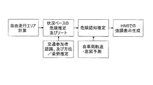
本発明は、自車両20の自由走行エリア(free driving area)に近い一つ以上の交通参加者30、40、50、60の各々の向きから、自車両20に関する一つ以上の潜在的危険を予測するものであり、運転者の運転動作を監視して、来るべき危険に運転者が気付いていないことが示唆されるときは、自車両20の運転者に警告を発することができる。ADAS10は、走行処理として以下の処理ステップを継続して行う。
The present invention eliminates one or more potential hazards associated with the
一つ以上の視覚センサ11a、11b(例えばカメラやその他の適切な光センサ又はレーザセンサ)は、少なくとも自車両20の前方エリアを監視し、その後の処理のためにセンサデータS11a、S11b(例えば画像データ)を、ADAS10が備える処理手段(演算ユニット12)に継続的に出力する。カメラ11a、11bは、自車両20の両側方又は後方もモニタすることができる。センサデータS11a、S11b(例えば、一つ以上のカメラ11a、11bから取得した画像)に基づいて、自車両20の自由走行エリアを特定することができる。自由走行エリアとは、当該エリア内にすでに存在する物体(例えば、交通参加者や障害物)に衝突することなく自車両20が安全に走行して到達することのできるエリア又は通過することのできるエリアを意味する。
One or more
この自由走行エリアは、マーク、標識、一般的な運転規則により示されるような法的に走行可能なエリアに関する情報により、さらに明確となる。このような情報はナビゲーションシステム(例えばGPS)やインターネットから得ることができる。自由走行エリアは、例えば、欧州特許出願第11183057号明細書に記載された道路地形検出方法に従って、解析し特定することができる。 This free-running area is further clarified by information on areas that can be legally traveled as indicated by marks, signs, and general driving rules. Such information can be obtained from a navigation system (eg, GPS) or the Internet. The free running area can be analyzed and specified in accordance with, for example, the road landform detection method described in European Patent Application No. 11183057.
このような道路地形検出方法は、センサ11a、11bの少なくとも一つを用いて車両の環境を検知するステップと、センサ信号S11a、S11bを、少なくとも一つの基本分類器を用いて、環境内の局所的な特徴物についての少なくとも一つの信頼度マップ(confidence map)に変換するステップと、上記少なくとも一つの信頼度マップに基づいて、上記局所的な特徴物についての空間特徴を生成するステップと、当該生成した空間特徴に基づいて、自車両20の環境における位置を、道路地形の或るカテゴリに分類するステップと、を備える。この信頼度マップには、対応する位置(例えば、ピクセル位置や距離空間におけるセル)が或る特徴物を持つか否かについての信頼度情報が含まれる。したがって、信頼度マップは、例えば空間表現における各位置について、当該位置に特徴物が存在する信頼度を表わしている。基本分類器は、道路様領域(road-like area)から縁石等の道路境界を区別する視覚的特徴を見つけるための視覚的境界を分類する。自車両と他の交通参加者との衝突の危険性は、処理手段によって推定される。
Such a road terrain detection method uses a step of detecting the environment of a vehicle using at least one of the
自由走行エリアの特定と並行して、カメラ11a、11bの少なくとも一つの視野に入るすべての交通参加者30、40、50、60が検出される。特に、交通参加者の位置及び速度が演算ユニット12によってカメラ画像に基づいて特定される。そして、カメラ画像から抽出された視覚的特徴を、例えばADAS10のメモリ14に保存されている視覚的特徴と比較することによって、交通参加者の向きが推定され追跡される。随意的に、上記抽出された視覚的特性(例えば、大きさ、形、色等)から、交通参加者30、40、50、60の種類も推定することができる。
In parallel with the specification of the free running area, all
自由走行エリアと、交通参加者の情報とが、状況(situation)ベースの危険度推定処理ステップにおいて解析される。 Free-running areas and traffic participant information are analyzed in a situation-based risk estimation process step.
既知の決定論的な軌道ベースの手法を用いて、動いている交通参加者と自車両20とが衝突する危険度を推定することができる。静止物体に関しては、その向き、すなわち、物体が動き始める可能性が最も高い方向に基づいて衝突の危険度を推定する。上記交通参加者の情報は自由走行エリアと比較され、ADAS10は、自車両20との衝突が起こり得るか否か、及び衝突発生の可能性がどの程度あるかを判断する。このような衝突発生の確率は危険度値によって表すことができ、有意な潜在的な危険は、この危険度値の評価に基づいて特定することができる。
A known deterministic trajectory-based method can be used to estimate the risk of collision between a moving traffic participant and the
自車両20の自由走行エリアにより近い物体、及び、自由走行エリアの方向を向いている物体は、この自由走行エリアからより遠い物体、及び、この自由走行エリアから離れる方向を向いている物体よりも自車両20と衝突する危険性が高い。これについては、図3に示す例を参照して後述する。結果として得られる各物体についての危険度、すなわち各交通参加者に関する危険度は、値によって表され、ソート(順位付け)される。
An object closer to the free running area of the
上記のような情報に基づいて警告を発すると、不要な警告を頻発してしまうこととなる場合がある。運転者がすでにその危険性に気づいている場合があるからである。運転者が気づいていることを明確に示すものの例として、車両の軌道をわずかに調整したり、自車両20の移動速度をわずかに低下させたりする反応が挙げられる。
If a warning is issued based on the above information, an unnecessary warning may occur frequently. This is because the driver may already be aware of the danger. As an example of clearly indicating that the driver is aware, there is a reaction that slightly adjusts the track of the vehicle or slightly decreases the moving speed of the
したがって、そのような情報を伝えることが、自車両軌道・意図予測モジュールの役割である。このため、ADAS10は、継続的に又は間隔をおいて、現在の速度、加速度、ハンドルの向き、方向指示器の設定等の、自車両20のパラメータを監視するものとすることができる。この予測は、危険認知推定モジュールにおいて危険度値と組み合わされる。起こり得る危険に対して運転者が反応していない、という明らかな危険性がある場合にのみ、自車両20のHMI22を用いて、例えば運転者の視界内で視覚的に、その危険の要因が強調される。音による警告も発することができる。
Therefore, it is the role of the vehicle trajectory / intention prediction module to convey such information. For this reason, the
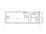
図2は、自車両20内に搭載可能なADAS10の概略図を示している。ADAS10は、センサ11a、11bの少なくとも一つを含む。センサ11a、11bは、好ましくはカメラであり、その視野(点線で示されている)内に存在する交通参加者を検出することができる。
FIG. 2 shows a schematic diagram of the
各センサ11a、11bは、演算ユニット12にセンサ信号S11a、S11bを出力する。演算ユニット12は、センサ信号S11a、S11bから視覚的特徴を抽出することができる。この抽出には、公知の画像処理アルゴリズム、例えば物体のエッジ検出を利用することができる。演算ユニット12は、さらにADAS10のメモリ14からデータを読み込んだりメモリ14との通信を行う。メモリ14には、例えば視覚的特徴が保存されている。さらに、演算ユニット12は、抽出された視覚的特徴を、保存されている視覚的特徴と比較して、交通参加者の向き、形、大きさ、又は種類を特定する。
Each
各センサ11a、11bは距離計測手段15を備えるものとすることができ、または、距離計測手段15に各センサ11a、11bが含まれるものとすることができる。距離計測手段15は、例えば継続的に交通参加者の距離を計測するための、光手段、レーザ手段、又はその他の手段とすることができる。演算ユニット12は、自車両20の自由走行エリア上の位置までの距離、すなわち、意図されている走行軌道上の地点であって、自車両20がその後到達するであろう地点までの距離を計算する。
Each
演算ユニット12は、センサデータS11a、S11bから交通参加者の移動方向を抽出することもできる。この抽出は、公知の画像解析技術を用いて行うことができる。
The
演算ユニット12は、検出した他の交通参加者の一つ又は複数に起因した潜在的な危険を特定した場合には、出力信号を生成する。この出力信号は、警告ユニット13によって受信され、当該信号を受信した警告ユニット13は、どのような動作をするべきか決定することができる。警告ユニット13は、自車両20の運転者に警告信号を表示するようHMI22に指示することができる。警告ユニット13は、また、自車両20の駆動システム21(モータ制御)の操作装置としても動作することができる。例えば、警告ユニット13は、自車両20の制動、減速、加速、ステアリングその他の動作を自動で誘導するものとすることができる。警告ユニット13は、自車両20に搭載されたコンピュータ23と通信して、潜在的な危険を運転者に通知したり、発生し得る衝突を回避すべく必要な動作を迅速に行うことができる。
The
図3は、本発明のADAS10を備えた自車両20が遭遇する交通状況の一例を示している。ADAS10は、少なくとも一つの前方カメラ11aを備える。この前方カメラ11aは、その視野(カメラ11aから伸びる点線で示されている)内の交通参加者30、40、50、60を検出する。ADAS10の演算ユニット12は、他の交通参加者30、40、50、60に関する視覚的特徴を、センサ(カメラ)信号Sllaから抽出することができる。この視覚的特徴により、演算ユニット12は、自車両20に対する各交通参加者の向き、特に自車両20の走行方向(軌道)に対する向きを特定することができる。この走行軌道は、演算ユニット12によって特定され、図3内に破線の矢印Aで示されている。
FIG. 3 shows an example of the traffic situation encountered by the
演算ユニット12は、例えば既知の(保存されている)視覚的特徴と比較することによって、視覚的特徴を解析して向きを決定することができる。演算ユニット12は、例えば交通参加者30、40、50、及び60の向きB、C、D、及びEを、それぞれ特定する。車30や自転車40のような車両に関しては、車両の後部と前部とを識別することによって向きが特定され、例えば後部から前部へ向かう方向を向きとすることができる。歩行者に関しては、顔認識や、歩行者の外観を決定する他の顕著な視覚的特徴によって、向きを特定することができる。
The
図3に見られるように、交通参加者の向き、特に、移動していない交通参加者の向きは、当該交通参加者のその後の動きを推定するための良い指標となる。演算ユニット12は、特定した向きに基づいて、潜在的な危険を予測する。
As seen in FIG. 3, the traffic participant orientation, in particular, not moving direction of traffic participants is a good indicator for estimating subsequent movement of the traffic participant. The
図3では、交通参加者60に関しては、危険が発生する可能性は低いと考えられる。当該交通参加者の向きは、自車両20について推定された走行軌道から離れる方向を向いている。歩行者60は、自車両20の軌道から離れる方向に移動する可能性が最も高い。したがって、衝突の危険性は低い。
In FIG. 3, regarding the traffic participant 60, it is considered that the possibility of danger is low. The direction of the traffic participant is facing away from the travel path estimated for the
しかし、交通参加者40は、その向きが自車両20の走行軌道に対し密接な関係性を有しており、衝突の危険度が高い。
However, traffic participants 40, its direction has a close relationship to the travel trajectory of the
交通参加者50の場合も同様である。しかし、歩行者50はまだ自車両20の自由走行エリアからかなり離れているため、潜在的危険は密接な関係性を有すると言えるほど十分には高くない。仮に歩行者50が自車両20の自由走行エリアに向かう方向に移動し始めたとすれば、この状況は明らかに変化する。潜在的危険を特定するため、演算ユニット12は交通参加者の種類を特定する。その後、演算ユニット12は、特定した交通参加者の既知の(保存されている)特性、例えば速度を考慮に入れることができる。歩行者は、車両よりゆっくり移動する。
The same applies to the
要約すると、本発明は、ADAS10を提供する。当該ADAS10は、より長いタイムスケールで動作し、危険に反応して衝突の影響を和らげるだけでなく、来るべき危険から遠ざけるように運転者及び自車両を誘導する。これを行うため、他の交通参加者30、40、50、60の向き(すなわち姿勢)、自車両20が走行する可能性のあるエリア、及び/又は運転者によって意図された自車両20の走行軌道を含む情報を考慮して、潜在的危険を特定する。
In summary, the present invention provides
Claims (15)
演算ユニットと、
を備え、
前記演算ユニットは、
前記少なくとも一つのセンサ(11a、11b)からセンサ信号(S11a、S11b)を受信し、
当該センサ信号(S11a、S11b)から、前記検出された交通参加者のそれぞれについての、当該交通参加者が移動している方向又は移動し始める可能性の最も高い方向を示す当該交通参加者の向きと、当該参加者の位置と、を特定し、
当該特定した前記各交通参加者の向き及び位置と自車両(20)の進行方向との関係に基づき、前記交通参加者のそれぞれについて自車両(20)に関連する一つ以上の潜在的危険の程度を表す危険度値を算出するものであり、
前記危険度値は、自車両が走行しようとするエリアにより近い交通参加者ほど、及び当該エリアに向いている交通参加者ほど、より高い危険を表す値に設定される、
車両用の高度運転者支援システム(10)。 At least one sensor (11a, 11b) for detecting one or more traffic participants (30, 40, 50, 60);
An arithmetic unit;
With
The arithmetic unit is
Receiving sensor signals (S11a, S11b) from the at least one sensor (11a, 11b);
The sensor signal (S11a, S11b) from the for each of the detected transportation participants of the traffic participants having the highest direction of possibly the traffic participant starts to have a direction or moving mobile identify and orientation, and position of the participants, the,
Based on the relationship between the direction and position of each identified traffic participant and the traveling direction of the vehicle (20), one or more potential hazards associated with the vehicle (20) for each of the traffic participants. provided for calculating the risk value representing the degree,
The risk value is set to a value representing a higher risk for traffic participants closer to the area where the vehicle is going to travel, and for traffic participants facing the area,
Advanced driver assistance system for a vehicle (10).
自車両の速度及び走行方向を含む走行パラメータを監視し、
当該走行パラメータに基づき、運転者が前記各交通参加者に気づいているか否かを判断し、
運転者が気づいていると判断される前記交通参加者に関しては警告信号を発しない、
よう構成されている、
請求項13に記載の高度運転者支援システム(10)。 The arithmetic unit is
Monitor driving parameters including the speed and direction of the vehicle,
Based on the travel parameters, determine whether the driver is aware of each traffic participant,
No warning signal is issued for the traffic participants that are determined to be noticed by the driver,
Configured as
The advanced driver assistance system (10) according to claim 13 .
前記センサにより、一つ以上の交通参加者(30、40、50、60)を検出するステップと、
前記演算ユニットが、当該演算ユニットの入力部を介して前記センサからセンサ信号(S11a、S11b)を受け取り、前記演算ユニットの演算部が、当該受け取った前記センサ信号から前記交通参加者のそれぞれについての、当該交通参加者が移動している方向又は移動し始める可能性の最も高い方向を示す当該交通参加者の自車両(20)に対する向きと、当該参加者の位置と、を特定するステップと、
前記演算部が、前記特定した前記各交通参加者の向き及び位置と自車両(20)の進行方向との関係に基づき、前記交通参加者毎の自車両(20)に関連する一つ以上の潜在的危険の程度を表す危険度値を算出するステップと、
を含み、
前記危険度値は、自車両が走行しようとするエリアにより近い交通参加者ほど、及び当該エリアに向いている交通参加者ほど、より高い危険を表す値に設定される、方法。 At least one sensor for detecting one or more traffic participants (30, 40, 50, 60) (11a, 11b), Advanced Driver assistance system for a vehicle having a computing unit, a (10) A method of operation,
Detecting one or more traffic participants (30, 40, 50, 60) by the sensor;
The operation unit receives the sensor signal from the sensor via the input unit of the operation unit (S11a, S11b), calculating unit of the operation unit, respective front Ki交 communication participants from the sensor signals received the for, identifying and orientation with respect to the traffic participant the the highest direction may begin to to have a direction or moving the moving traffic participants of the vehicle (20), the position of the participants, the When,
One or more of the calculation unit is related to the vehicle (20) for each traffic participant based on the relationship between the direction and position of each identified traffic participant and the traveling direction of the vehicle (20). Calculating a risk value representing the degree of potential danger;
Including
The risk level value is set to a value representing a higher risk for a traffic participant closer to an area where the vehicle is going to travel and a traffic participant facing the area.
Applications Claiming Priority (2)
| Application Number | Priority Date | Filing Date | Title |
|---|---|---|---|
| EP12164976.8A EP2654028B1 (en) | 2012-04-20 | 2012-04-20 | Orientation sensitive traffic collision warning system |
| EP12164976.8 | 2012-04-20 |
Publications (3)
| Publication Number | Publication Date |
|---|---|
| JP2013225295A JP2013225295A (en) | 2013-10-31 |
| JP2013225295A5 JP2013225295A5 (en) | 2016-03-31 |
| JP5938569B2 true JP5938569B2 (en) | 2016-06-22 |
Family
ID=45954528
Family Applications (1)
| Application Number | Title | Priority Date | Filing Date |
|---|---|---|---|
| JP2013045109A Expired - Fee Related JP5938569B2 (en) | 2012-04-20 | 2013-03-07 | Advanced driver support system considering azimuth information and operation method thereof |
Country Status (3)
| Country | Link |
|---|---|
| US (1) | US9524643B2 (en) |
| EP (1) | EP2654028B1 (en) |
| JP (1) | JP5938569B2 (en) |
Families Citing this family (23)
| Publication number | Priority date | Publication date | Assignee | Title |
|---|---|---|---|---|
| DE102010031038A1 (en) * | 2010-07-07 | 2012-01-12 | Robert Bosch Gmbh | Method for assisting a driver of a motor vehicle |
| US20150278729A1 (en) * | 2014-03-28 | 2015-10-01 | International Business Machines Corporation | Cognitive scoring of asset risk based on predictive propagation of security-related events |
| EP2950294B1 (en) * | 2014-05-30 | 2019-05-08 | Honda Research Institute Europe GmbH | Method and vehicle with an advanced driver assistance system for risk-based traffic scene analysis |
| US9947215B2 (en) * | 2014-09-26 | 2018-04-17 | Harman International Industries, Incorporated | Pedestrian information system |
| JP6413621B2 (en) * | 2014-10-22 | 2018-10-31 | 株式会社デンソー | On-vehicle object discrimination device |
| US9440649B2 (en) | 2014-10-29 | 2016-09-13 | Robert Bosch Gmbh | Impact mitigation by intelligent vehicle positioning |
| KR20160054825A (en) * | 2014-11-07 | 2016-05-17 | 현대모비스 주식회사 | Apparatus and method for judging drivable space |
| US9505413B2 (en) | 2015-03-20 | 2016-11-29 | Harman International Industries, Incorporated | Systems and methods for prioritized driver alerts |
| JP6819594B2 (en) * | 2015-08-28 | 2021-01-27 | ソニー株式会社 | Information processing equipment, information processing methods and programs |
| DE102015224171A1 (en) * | 2015-12-03 | 2017-06-08 | Robert Bosch Gmbh | Tilt detection on two-wheeled vehicles |
| WO2018142394A2 (en) * | 2017-02-06 | 2018-08-09 | Vayavision Sensing Ltd. | Computer aided driving |
| DE102017201936A1 (en) * | 2017-02-08 | 2018-08-09 | Robert Bosch Gmbh | Method for reducing collision damage |
| EP3409553B1 (en) * | 2017-06-01 | 2021-08-04 | Honda Research Institute Europe GmbH | System and method for automated execution of a maneuver or behavior of a system |
| WO2019064490A1 (en) * | 2017-09-29 | 2019-04-04 | 本田技研工業株式会社 | Vehicle control device, vehicle control method, and program |
| US11195410B2 (en) * | 2018-01-09 | 2021-12-07 | Continental Automotive Systems, Inc. | System and method for generating a traffic heat map |
| US11505181B2 (en) * | 2019-01-04 | 2022-11-22 | Toyota Motor Engineering & Manufacturing North America, Inc. | System, method, and computer-readable storage medium for vehicle collision avoidance on the highway |
| US11544935B2 (en) | 2020-02-26 | 2023-01-03 | Honda Motor Co., Ltd. | System for risk object identification via causal inference and method thereof |
| US11458987B2 (en) * | 2020-02-26 | 2022-10-04 | Honda Motor Co., Ltd. | Driver-centric risk assessment: risk object identification via causal inference with intent-aware driving models |
| US11491976B2 (en) * | 2020-04-21 | 2022-11-08 | Baidu Usa Llc | Collision warning system for safety operators of autonomous vehicles |
| CN112124306B (en) * | 2020-09-29 | 2022-08-09 | 深圳东和邦泰科技有限公司 | Vehicle anti-collision control system and control method for new energy automobile |
| US11845464B2 (en) * | 2020-11-12 | 2023-12-19 | Honda Motor Co., Ltd. | Driver behavior risk assessment and pedestrian awareness |
| CN113189989B (en) * | 2021-04-21 | 2022-07-01 | 东风柳州汽车有限公司 | Vehicle intention prediction method, device, equipment and storage medium |
| US20230030815A1 (en) * | 2021-07-29 | 2023-02-02 | Argo AI, LLC | Complementary control system for an autonomous vehicle |
Family Cites Families (25)
| Publication number | Priority date | Publication date | Assignee | Title |
|---|---|---|---|---|
| JP2799375B2 (en) * | 1993-09-30 | 1998-09-17 | 本田技研工業株式会社 | Anti-collision device |
| DE10002778B4 (en) | 2000-01-22 | 2012-05-24 | Robert Groten | Use of a microfilament nonwoven fabric as a cleaning cloth |
| US6687577B2 (en) * | 2001-12-19 | 2004-02-03 | Ford Global Technologies, Llc | Simple classification scheme for vehicle/pole/pedestrian detection |
| US7079924B2 (en) * | 2002-11-07 | 2006-07-18 | The Regents Of The University Of California | Vision-based obstacle avoidance |
| JP4546956B2 (en) * | 2003-06-12 | 2010-09-22 | 本田技研工業株式会社 | Target orientation estimation using depth detection |
| JP2006218935A (en) * | 2005-02-09 | 2006-08-24 | Advics:Kk | Traveling supporting device for vehicle |
| US20080065328A1 (en) * | 2006-09-08 | 2008-03-13 | Andreas Eidehall | Method and system for collision avoidance |
| JP2008279842A (en) * | 2007-05-09 | 2008-11-20 | Matsushita Electric Ind Co Ltd | Dead angle zone estimation device |
| JP4207088B2 (en) * | 2007-06-20 | 2009-01-14 | トヨタ自動車株式会社 | Vehicle travel estimation device |
| JP4900103B2 (en) * | 2007-07-18 | 2012-03-21 | マツダ株式会社 | Pedestrian detection device |
| EP2055835A1 (en) * | 2007-10-30 | 2009-05-06 | Saab Ab | Method and arrangement for determining position of vehicles relative each other |
| JP4893593B2 (en) * | 2007-11-13 | 2012-03-07 | マツダ株式会社 | Vehicle driving support device |
| JP5283967B2 (en) * | 2008-05-14 | 2013-09-04 | 日立オートモティブシステムズ株式会社 | In-vehicle object detection device |
| JP5345350B2 (en) * | 2008-07-30 | 2013-11-20 | 富士重工業株式会社 | Vehicle driving support device |
| DE102008049824B4 (en) * | 2008-10-01 | 2014-09-04 | Universität Kassel | Method for collision avoidance |
| DE102008062916A1 (en) * | 2008-12-23 | 2010-06-24 | Continental Safety Engineering International Gmbh | Method for determining a collision probability of a vehicle with a living being |
| JP4853525B2 (en) * | 2009-02-09 | 2012-01-11 | トヨタ自動車株式会社 | Moving region prediction device |
| JP4819919B2 (en) * | 2009-04-16 | 2011-11-24 | 本田技研工業株式会社 | Vehicle object detection device |
| EP2246806B1 (en) * | 2009-04-29 | 2014-04-02 | Autoliv Development AB | Vision method and system for automatically detecting objects in front of a motor vehicle |
| JP2011113120A (en) * | 2009-11-24 | 2011-06-09 | Toyota Motor Corp | Vehicle-surrounding monitoring apparatus |
| US8509982B2 (en) * | 2010-10-05 | 2013-08-13 | Google Inc. | Zone driving |
| US8818702B2 (en) * | 2010-11-09 | 2014-08-26 | GM Global Technology Operations LLC | System and method for tracking objects |
| EP2574958B1 (en) | 2011-09-28 | 2017-02-22 | Honda Research Institute Europe GmbH | Road-terrain detection method and system for driver assistance systems |
| US20130238181A1 (en) * | 2012-03-12 | 2013-09-12 | Toyota Motor Eng. & Man. North America (Tema) | On-board vehicle path prediction using processed sensor information |
| US8949012B2 (en) * | 2012-04-05 | 2015-02-03 | Her Majesty The Queen In Right Of Canada, As Represented By The Minister Of National Defence | Automated multi-vehicle position, orientation and identification system and method |
-
2012
- 2012-04-20 EP EP12164976.8A patent/EP2654028B1/en not_active Not-in-force
-
2013
- 2013-03-07 JP JP2013045109A patent/JP5938569B2/en not_active Expired - Fee Related
- 2013-04-16 US US13/863,563 patent/US9524643B2/en active Active
Also Published As
| Publication number | Publication date |
|---|---|
| EP2654028A1 (en) | 2013-10-23 |
| JP2013225295A (en) | 2013-10-31 |
| EP2654028B1 (en) | 2018-09-26 |
| US9524643B2 (en) | 2016-12-20 |
| US20130282268A1 (en) | 2013-10-24 |
Similar Documents
| Publication | Publication Date | Title |
|---|---|---|
| JP5938569B2 (en) | Advanced driver support system considering azimuth information and operation method thereof | |
| EP3361466B1 (en) | Risk-based driver assistance for approaching intersections of limited visibility | |
| US10627228B2 (en) | Object detection device | |
| US9965957B2 (en) | Driving support apparatus and driving support method | |
| JP5971341B2 (en) | Object detection device and driving support device | |
| CN109841088B (en) | Vehicle driving assistance system and method | |
| JP2013225295A5 (en) | ||
| US10336252B2 (en) | Long term driving danger prediction system | |
| KR20180060860A (en) | Collision avoidance apparatus and method preventing collision between objects | |
| JP2016001463A (en) | Processor, processing system, processing program, and processing method | |
| JP2016001464A (en) | Processor, processing system, processing program, and processing method | |
| JP2016001170A (en) | Processing unit, processing program and processing method | |
| US11003925B2 (en) | Event prediction system, event prediction method, program, and recording medium having same recorded therein | |
| JP5587170B2 (en) | Driving support device and program | |
| TW201704067A (en) | Collision avoidance method, computer program product for said collision avoidance method and collision avoidance system | |
| JPWO2014192137A1 (en) | Moving track prediction apparatus and moving track prediction method | |
| KR20110067359A (en) | Method and apparatus for collision avoidance of vehicle | |
| KR20130007243A (en) | Method and system for warning forward collision using camera | |
| JP5898001B2 (en) | Vehicle periphery monitoring device | |
| JP2013173416A (en) | Vehicle traveling support device | |
| CN113771867A (en) | Method and device for predicting driving state and terminal equipment | |
| KR102279754B1 (en) | Method, apparatus, server, and computer program for preventing crash accident | |
| WO2023179494A1 (en) | Danger early warning method and apparatus, and vehicle | |
| JP5747593B2 (en) | Standard vehicle speed calculation device and program | |
| JP2024031048A (en) | Vehicle control device, vehicle control method, and vehicle control computer program |
Legal Events
| Date | Code | Title | Description |
|---|---|---|---|
| A977 | Report on retrieval |
Free format text: JAPANESE INTERMEDIATE CODE: A971007 Effective date: 20140430 |
|
| A131 | Notification of reasons for refusal |
Free format text: JAPANESE INTERMEDIATE CODE: A131 Effective date: 20140501 |
|
| A521 | Request for written amendment filed |
Free format text: JAPANESE INTERMEDIATE CODE: A523 Effective date: 20140703 |
|
| A02 | Decision of refusal |
Free format text: JAPANESE INTERMEDIATE CODE: A02 Effective date: 20140819 |
|
| A521 | Request for written amendment filed |
Free format text: JAPANESE INTERMEDIATE CODE: A523 Effective date: 20141217 |
|
| RD02 | Notification of acceptance of power of attorney |
Free format text: JAPANESE INTERMEDIATE CODE: A7422 Effective date: 20141217 |
|
| A911 | Transfer to examiner for re-examination before appeal (zenchi) |
Free format text: JAPANESE INTERMEDIATE CODE: A911 Effective date: 20141226 |
|
| A912 | Re-examination (zenchi) completed and case transferred to appeal board |
Free format text: JAPANESE INTERMEDIATE CODE: A912 Effective date: 20150213 |
|
| A521 | Request for written amendment filed |
Free format text: JAPANESE INTERMEDIATE CODE: A523 Effective date: 20160203 |
|
| A524 | Written submission of copy of amendment under article 19 pct |
Free format text: JAPANESE INTERMEDIATE CODE: A524 Effective date: 20160203 |
|
| A61 | First payment of annual fees (during grant procedure) |
Free format text: JAPANESE INTERMEDIATE CODE: A61 Effective date: 20160324 |
|
| R150 | Certificate of patent or registration of utility model |
Ref document number: 5938569 Country of ref document: JP Free format text: JAPANESE INTERMEDIATE CODE: R150 |
|
| RD02 | Notification of acceptance of power of attorney |
Free format text: JAPANESE INTERMEDIATE CODE: R3D02 |
|
| R250 | Receipt of annual fees |
Free format text: JAPANESE INTERMEDIATE CODE: R250 |
|
| R250 | Receipt of annual fees |
Free format text: JAPANESE INTERMEDIATE CODE: R250 |
|
| R250 | Receipt of annual fees |
Free format text: JAPANESE INTERMEDIATE CODE: R250 |
|
| R250 | Receipt of annual fees |
Free format text: JAPANESE INTERMEDIATE CODE: R250 |
|
| LAPS | Cancellation because of no payment of annual fees |