JP5937456B2 - Substrate cleaning device and substrate cleaning unit - Google Patents
Substrate cleaning device and substrate cleaning unit Download PDFInfo
- Publication number
- JP5937456B2 JP5937456B2 JP2012175266A JP2012175266A JP5937456B2 JP 5937456 B2 JP5937456 B2 JP 5937456B2 JP 2012175266 A JP2012175266 A JP 2012175266A JP 2012175266 A JP2012175266 A JP 2012175266A JP 5937456 B2 JP5937456 B2 JP 5937456B2
- Authority
- JP
- Japan
- Prior art keywords
- cleaning body
- base member
- cleaning
- unit
- substrate
- Prior art date
- Legal status (The legal status is an assumption and is not a legal conclusion. Google has not performed a legal analysis and makes no representation as to the accuracy of the status listed.)
- Active
Links
- 238000004140 cleaning Methods 0.000 title claims description 287
- 239000000758 substrate Substances 0.000 title claims description 120
- 238000001514 detection method Methods 0.000 claims description 98
- 230000007246 mechanism Effects 0.000 claims description 56
- 230000003028 elevating effect Effects 0.000 claims description 19
- 230000005540 biological transmission Effects 0.000 claims description 11
- 235000012431 wafers Nutrition 0.000 description 70
- 238000000034 method Methods 0.000 description 27
- 230000008569 process Effects 0.000 description 18
- 238000005406 washing Methods 0.000 description 6
- 238000010586 diagram Methods 0.000 description 3
- 230000033001 locomotion Effects 0.000 description 2
- 230000004048 modification Effects 0.000 description 2
- 238000012986 modification Methods 0.000 description 2
- 230000002093 peripheral effect Effects 0.000 description 2
- XUIMIQQOPSSXEZ-UHFFFAOYSA-N Silicon Chemical compound [Si] XUIMIQQOPSSXEZ-UHFFFAOYSA-N 0.000 description 1
- 230000008859 change Effects 0.000 description 1
- 150000001875 compounds Chemical class 0.000 description 1
- 230000007423 decrease Effects 0.000 description 1
- 238000001035 drying Methods 0.000 description 1
- 230000000694 effects Effects 0.000 description 1
- 230000006872 improvement Effects 0.000 description 1
- 239000007788 liquid Substances 0.000 description 1
- 230000003287 optical effect Effects 0.000 description 1
- 239000004065 semiconductor Substances 0.000 description 1
- 238000000926 separation method Methods 0.000 description 1
- 229910052710 silicon Inorganic materials 0.000 description 1
- 239000010703 silicon Substances 0.000 description 1
- 239000000126 substance Substances 0.000 description 1
- XLYOFNOQVPJJNP-UHFFFAOYSA-N water Substances O XLYOFNOQVPJJNP-UHFFFAOYSA-N 0.000 description 1
Images


Classifications
-
- B—PERFORMING OPERATIONS; TRANSPORTING
- B08—CLEANING
- B08B—CLEANING IN GENERAL; PREVENTION OF FOULING IN GENERAL
- B08B1/00—Cleaning by methods involving the use of tools
- B08B1/10—Cleaning by methods involving the use of tools characterised by the type of cleaning tool
- B08B1/12—Brushes
-
- H—ELECTRICITY
- H01—ELECTRIC ELEMENTS
- H01L—SEMICONDUCTOR DEVICES NOT COVERED BY CLASS H10
- H01L21/00—Processes or apparatus adapted for the manufacture or treatment of semiconductor or solid state devices or of parts thereof
- H01L21/67—Apparatus specially adapted for handling semiconductor or electric solid state devices during manufacture or treatment thereof; Apparatus specially adapted for handling wafers during manufacture or treatment of semiconductor or electric solid state devices or components ; Apparatus not specifically provided for elsewhere
- H01L21/67005—Apparatus not specifically provided for elsewhere
- H01L21/67011—Apparatus for manufacture or treatment
- H01L21/67017—Apparatus for fluid treatment
- H01L21/67028—Apparatus for fluid treatment for cleaning followed by drying, rinsing, stripping, blasting or the like
- H01L21/6704—Apparatus for fluid treatment for cleaning followed by drying, rinsing, stripping, blasting or the like for wet cleaning or washing
- H01L21/67046—Apparatus for fluid treatment for cleaning followed by drying, rinsing, stripping, blasting or the like for wet cleaning or washing using mainly scrubbing means, e.g. brushes
-
- H—ELECTRICITY
- H01—ELECTRIC ELEMENTS
- H01L—SEMICONDUCTOR DEVICES NOT COVERED BY CLASS H10
- H01L21/00—Processes or apparatus adapted for the manufacture or treatment of semiconductor or solid state devices or of parts thereof
- H01L21/02—Manufacture or treatment of semiconductor devices or of parts thereof
- H01L21/04—Manufacture or treatment of semiconductor devices or of parts thereof the devices having potential barriers, e.g. a PN junction, depletion layer or carrier concentration layer
- H01L21/18—Manufacture or treatment of semiconductor devices or of parts thereof the devices having potential barriers, e.g. a PN junction, depletion layer or carrier concentration layer the devices having semiconductor bodies comprising elements of Group IV of the Periodic Table or AIIIBV compounds with or without impurities, e.g. doping materials
- H01L21/30—Treatment of semiconductor bodies using processes or apparatus not provided for in groups H01L21/20 - H01L21/26
- H01L21/302—Treatment of semiconductor bodies using processes or apparatus not provided for in groups H01L21/20 - H01L21/26 to change their surface-physical characteristics or shape, e.g. etching, polishing, cutting
-
- H—ELECTRICITY
- H01—ELECTRIC ELEMENTS
- H01L—SEMICONDUCTOR DEVICES NOT COVERED BY CLASS H10
- H01L21/00—Processes or apparatus adapted for the manufacture or treatment of semiconductor or solid state devices or of parts thereof
- H01L21/67—Apparatus specially adapted for handling semiconductor or electric solid state devices during manufacture or treatment thereof; Apparatus specially adapted for handling wafers during manufacture or treatment of semiconductor or electric solid state devices or components ; Apparatus not specifically provided for elsewhere
- H01L21/67005—Apparatus not specifically provided for elsewhere
- H01L21/67242—Apparatus for monitoring, sorting or marking
- H01L21/67253—Process monitoring, e.g. flow or thickness monitoring
Landscapes
- Engineering & Computer Science (AREA)
- Physics & Mathematics (AREA)
- Condensed Matter Physics & Semiconductors (AREA)
- General Physics & Mathematics (AREA)
- Manufacturing & Machinery (AREA)
- Computer Hardware Design (AREA)
- Microelectronics & Electronic Packaging (AREA)
- Power Engineering (AREA)
- Cleaning Or Drying Semiconductors (AREA)
Description
開示の実施形態は、基板洗浄装置および基板洗浄ユニットに関する。 Embodiments disclosed herein relate to a substrate cleaning apparatus and a substrate cleaning unit.
従来、シリコンウェハや化合物半導体ウェハ等の基板の洗浄方式として、スクラブ洗浄方式が知られている。スクラブ洗浄方式は、回転するブラシやスポンジを基板の表面に接触させて、表面に付着した異物を除去する洗浄方式である。 Conventionally, a scrub cleaning method is known as a method for cleaning a substrate such as a silicon wafer or a compound semiconductor wafer. The scrub cleaning method is a cleaning method in which a rotating brush or sponge is brought into contact with the surface of a substrate to remove foreign substances adhering to the surface.
スクラブ洗浄方式を採用する基板洗浄装置は、モータによって回転し且つエアシリンダによって上下動するシャフトの下端部にブラシ等の洗浄体を備えており、エアシリンダが発生させる浮力を調整することによって洗浄体の基板への接触圧を調整する。従来の基板洗浄装置は、洗浄体やシャフト等の合計重量を検知するセンサを備えており、予め設定された所望の接触圧と上記センサからの出力との差分だけエアシリンダの浮力を発生させることによって、所望の接触圧を得ることができる。 A substrate cleaning apparatus that employs a scrub cleaning system includes a cleaning body such as a brush at the lower end of a shaft that is rotated by a motor and moved up and down by an air cylinder, and the cleaning body is adjusted by adjusting the buoyancy generated by the air cylinder. The contact pressure to the substrate is adjusted. A conventional substrate cleaning apparatus includes a sensor that detects a total weight of a cleaning body, a shaft, and the like, and generates buoyancy of an air cylinder by a difference between a preset desired contact pressure and an output from the sensor. Thus, a desired contact pressure can be obtained.
一方、従来の基板洗浄装置では、洗浄体のシャフトを回転させるためのモータが、シャフトと別体に設けられており、モータの出力軸に取り付けられたプーリとシャフトに取り付けられたプーリとの間に掛け回された伝達ベルトによってモータの回転をシャフトへ伝達して洗浄体を回転させていた(特許文献1参照)。 On the other hand, in the conventional substrate cleaning apparatus, the motor for rotating the shaft of the cleaning body is provided separately from the shaft, and between the pulley attached to the output shaft of the motor and the pulley attached to the shaft. The cleaning body is rotated by transmitting the rotation of the motor to the shaft by the transmission belt wound around (see Patent Document 1).
しかしながら、従来の基板洗浄装置には、洗浄体の基板への接触圧を正確に検知するという点でさらなる改善の余地があった。 However, the conventional substrate cleaning apparatus has room for further improvement in that the contact pressure of the cleaning body to the substrate is accurately detected.
たとえば、洗浄体は、基板表面の凹凸によって上下動することがある。このような場合、シャフトに取り付けられたプーリはシャフトとともに上下動するが、モータに取り付けられたプーリは上下動しないため、これらのプーリ間に掛け回されたベルトが斜めになり、この影響が圧力センサへ伝わって正確な検知結果が得られない可能性があった。 For example, the cleaning body may move up and down due to irregularities on the substrate surface. In such a case, the pulley attached to the shaft moves up and down together with the shaft, but the pulley attached to the motor does not move up and down. There is a possibility that accurate detection results may not be obtained when transmitted to the sensor.
実施形態の一態様は、洗浄体の基板への接触圧を正確に検知することのできる基板洗浄装置および基板洗浄ユニットを提供することを目的とする。 An object of one embodiment is to provide a substrate cleaning apparatus and a substrate cleaning unit that can accurately detect a contact pressure of a cleaning body on a substrate.
実施形態の一態様に係る基板洗浄装置は、洗浄体ヘッド部と、第1荷重検知部と、浮力付与部とを備える。洗浄体ヘッド部は、洗浄体と、洗浄体を支持するシャフトと、シャフトを回転させる回転機構と、これらを一体的に保持するベース部材とを備える。第1荷重検知部は、一端側が洗浄体ヘッド部のベース部材に連結され、洗浄体ヘッド部から受ける荷重を検知する。浮力付与部は、第1荷重検知部を介して洗浄体ヘッド部に浮力を与える。また、浮力付与部は、第2ベース部材と、ガイド部と、昇降機構と、第3ベース部材とを備える。第2ベース部材は、第1荷重検知部の他端側に連結される。ガイド部は、第2ベース部材を昇降可能に支持する。昇降機構は、第2ベース部材を昇降させる。第3ベース部材は、昇降機構およびガイド部を保持する。 A substrate cleaning apparatus according to an aspect of an embodiment includes a cleaning body head unit, a first load detection unit, and a buoyancy imparting unit. The cleaning body head unit includes a cleaning body, a shaft that supports the cleaning body, a rotation mechanism that rotates the shaft, and a base member that integrally holds these. The first load detection unit is connected at one end to the base member of the cleaning body head unit and detects a load received from the cleaning body head unit. The buoyancy imparting unit imparts buoyancy to the cleaning body head unit via the first load detection unit. The buoyancy imparting unit includes a second base member, a guide unit, an elevating mechanism, and a third base member. The second base member is coupled to the other end side of the first load detection unit. A guide part supports the 2nd base member so that raising and lowering is possible. The elevating mechanism elevates and lowers the second base member. The third base member holds the lifting mechanism and the guide part.
実施形態の一態様によれば、洗浄体の基板への接触圧を正確に検知することができる。 According to one aspect of the embodiment, the contact pressure of the cleaning body on the substrate can be accurately detected.
以下、添付図面を参照して、本願の開示する基板洗浄装置および基板洗浄ユニットの実施形態を詳細に説明する。なお、以下に示す実施形態によりこの発明が限定されるものではない。 Hereinafter, embodiments of a substrate cleaning apparatus and a substrate cleaning unit disclosed in the present application will be described in detail with reference to the accompanying drawings. In addition, this invention is not limited by embodiment shown below.
(第1の実施形態)
まず、第1の実施形態に係るスクラブ洗浄ユニットの概略構成について図1を用いて説明する。図1は、スクラブ洗浄ユニットの構成を示す模式平面図である。
(First embodiment)
First, a schematic configuration of the scrub cleaning unit according to the first embodiment will be described with reference to FIG. FIG. 1 is a schematic plan view showing the configuration of the scrub cleaning unit.
なお、以下においては、位置関係を明確にするために、互いに直交するX軸、Y軸およびZ軸を規定し、Z軸正方向を鉛直上向き方向とする。 In the following, in order to clarify the positional relationship, the X axis, the Y axis, and the Z axis that are orthogonal to each other are defined, and the positive direction of the Z axis is the vertically upward direction.
図1に示すように、第1の実施形態に係るスクラブ洗浄ユニット100は、本願の開示する基板洗浄ユニットの一例であり、チャンバ3内に、基板洗浄装置1と、基板保持装置2とを備える。
As shown in FIG. 1, a
基板洗浄装置1は、基板保持装置2によって保持されたウェハWに対してスクラブ洗浄を行う装置である。具体的には、基板洗浄装置1には、ブラシやスポンジなどの洗浄体11が回転可能に設けられており、洗浄体11をウェハWに接触させた状態で洗浄体11を回転させることによって、ウェハWの表面に付着した異物を除去する。
The substrate cleaning device 1 is a device that performs scrub cleaning on the wafer W held by the
また、基板洗浄装置1の基端部には、洗浄体11を鉛直方向に沿って移動させる昇降機構50と、昇降機構50をX軸方向に沿って水平に移動させる移動機構55とが設けられる。基板洗浄装置1は、洗浄体11を回転させたのち、昇降機構50を用いて洗浄体11を降下させてウェハWの表面に接触させ、さらに、移動機構55を用いて昇降機構50を移動させることにより、後述する基板保持装置2によって回転するウェハWの表面全体をスクラブ洗浄する。
In addition, a
基板保持装置2は、ウェハWを水平に保持するとともに、保持したウェハWを鉛直軸回りに回転させる回転保持機構2aと、回転保持機構2aを取り囲むように配置されたカップ2bとを備える。かかる基板保持装置2は、回転保持機構2aによってウェハWを回転させるとともに、ウェハWの回転による遠心力によってウェハWの外方へ飛散する洗浄液をカップ2bによって回収する。
The
なお、基板保持装置2は、ウェハW上にDIW(純水)を供給するためのノズル2cを備えるており、後述する基板洗浄処理中に、かかるノズル2cからウェハW上にDIWを供給することによって、ウェハWの表面の乾燥を防止することとしている。ここでは、ノズル2cがカップ2bの上部に設けられるものとするが、ノズル2cを処理位置まで旋回させる旋回機構をチャンバ3内に設け、かかる旋回機構の先端にノズル2cを設けてもよい。
The
また、スクラブ洗浄ユニット100は、チャンバ3の外部に制御装置4を備える。制御装置4は、スクラブ洗浄ユニット100の動作を制御する装置である。かかる制御装置4は、たとえばコンピュータであり、図示しない制御部と記憶部とを備える。記憶部には、基板洗浄処理等の各種の処理を制御するプログラムが格納される。制御部は記憶部に記憶されたプログラムを読み出して実行することによってスクラブ洗浄ユニット100の動作を制御する。
In addition, the
なお、かかるプログラムは、コンピュータによって読み取り可能な記録媒体に記録されていたものであって、その記録媒体から制御装置4の記憶部にインストールされたものであってもよい。コンピュータによって読み取り可能な記録媒体としては、たとえばハードディスク(HD)、フレキシブルディスク(FD)、コンパクトディスク(CD)、マグネットオプティカルディスク(MO)、メモリカードなどがある。 Such a program may be recorded on a computer-readable recording medium, and may be installed in the storage unit of the control device 4 from the recording medium. Examples of the computer-readable recording medium include a hard disk (HD), a flexible disk (FD), a compact disk (CD), a magnetic optical disk (MO), and a memory card.
ここで、スクラブ洗浄方式を採用する基板洗浄装置は、洗浄体を支持するシャフトをエアシリンダ等を用いて所定の浮力で持ち上げることによって、洗浄体のウェハへの接触圧を調整している。具体的には、洗浄体やシャフト等の合計重量を検知するセンサを備え、予め設定された所望の接触圧と上記センサからの出力との差分だけエアシリンダの浮力を生じさせることによって、所望の接触圧を得ることができる。 Here, the substrate cleaning apparatus adopting the scrub cleaning method adjusts the contact pressure of the cleaning body to the wafer by lifting the shaft supporting the cleaning body with a predetermined buoyancy using an air cylinder or the like. Specifically, a sensor that detects the total weight of the cleaning body, the shaft, and the like is provided, and a desired buoyancy of the air cylinder is generated by a difference between a preset desired contact pressure and an output from the sensor. Contact pressure can be obtained.
しかしながら、従来の基板洗浄装置では、洗浄体のシャフトを回転させるためのモータが、シャフトとは別体に設けられており、モータの出力軸に取り付けられたプーリとシャフトに取り付けられたプーリとの間に掛け回された伝達ベルトによってモータの回転をシャフトへ伝達し、洗浄体を回転させていた。このため、洗浄体がウェハ表面の凹凸によって上下動した場合に、プーリ間に掛け回されたベルトが斜めになり、洗浄体のウェハへの接触圧を正確に検知することができない可能性があった。 However, in the conventional substrate cleaning apparatus, a motor for rotating the shaft of the cleaning body is provided separately from the shaft, and a pulley attached to the output shaft of the motor and a pulley attached to the shaft are provided. The rotation of the motor was transmitted to the shaft by the transmission belt wound around, and the cleaning body was rotated. For this reason, when the cleaning body moves up and down due to the unevenness of the wafer surface, the belt wound around the pulleys is inclined, and the contact pressure of the cleaning body to the wafer may not be accurately detected. It was.
そこで、第1の実施形態に係る基板洗浄装置1は、洗浄体11のシャフトを回転させる回転機構や、洗浄体11のウェハWへの接触圧を検知するためのセンサの配置を工夫することにより、洗浄体11のウェハWへの接触圧を正確に検知することとした。以下では、かかる基板洗浄装置1の構成について具体的に説明する。
Therefore, the substrate cleaning apparatus 1 according to the first embodiment is devised by arranging a rotation mechanism that rotates the shaft of the cleaning
図2は、第1の実施形態に係る基板洗浄装置1の構成を示す模式側面図である。図2に示すように、基板洗浄装置1は、洗浄体ヘッド部10と、第1荷重検知部20と、浮力付与部30と、第2荷重検知部40と、昇降機構50とを備える。
FIG. 2 is a schematic side view showing the configuration of the substrate cleaning apparatus 1 according to the first embodiment. As shown in FIG. 2, the substrate cleaning apparatus 1 includes a cleaning
洗浄体ヘッド部10は、洗浄体11と、シャフト12と、回転機構13と、第1ベース部材14とを備える。洗浄体11は、ブラシやスポンジ等であり、下端面をウェハWの表面との対向面としている。シャフト12は、鉛直方向に延在する長尺状の部材であり、下端部が洗浄体11の上部に接続されることによって、洗浄体11を支持する。
The cleaning
回転機構13は、シャフト12を鉛直軸まわりに回転させる。具体的には、回転機構13は、モータ13aと、第1プーリ13bと、第2プーリ13cと、伝達ベルト13dとを備える。モータ13aは、シャフト12に隣接する位置に、出力軸がシャフト12と平行となる向きで設けられる。第1プーリ13bは、モータ13aの出力軸の先端部に取り付けられ、第2プーリ13cは、シャフト12の先端部に取り付けられる。これら第1プーリ13bおよび第2プーリ13cは、同一の高さに配置されて伝達ベルト13dが掛け渡される。
The
かかる回転機構13では、モータ13aが出力軸を回転させると、かかる出力軸の回転に伴って第1プーリ13bが回転する。第1プーリ13bの回転は、伝達ベルト13dによって第2プーリ13cへ伝達される。そして、第2プーリ13cが回転することによって、シャフト12および洗浄体11が回転する。
In the
第1ベース部材14は、洗浄体11、シャフト12および回転機構13を一体的に保持する部材であり、本体部14aと、支持部14bと、第1連結部14cとを備える。
The
本体部14aは、シャフト12とモータ13aを保持する。シャフト12およびモータ13aの出力軸は、かかる本体部14aから突出しており、かかる本体部14aの上方に第1プーリ13b、第2プーリ13cおよび伝達ベルト13dが配置される。なお、シャフト12は、軸受12aを介して本体部14aに回転可能に保持される。
The
支持部14bは、鉛直方向に延在する部材であり、下端部が本体部14aの上部に固定される。第1連結部14cは、水平方向に延在する部材であり、支持部14bの上部に設けられる。
The
このように、洗浄体ヘッド部10は、洗浄体11と、洗浄体11を支持するシャフト12と、シャフト12を回転させる回転機構13とが第1ベース部材14に一体的に保持された構成を有する。これにより、ウェハWの凹凸によって洗浄体11が上下動した場合に、回転機構13も一体となって上下動するため、従来のように一方のプーリのみが上下動して伝達ベルトが斜めになるといった事態が生じるおそれがない。
Thus, the cleaning
第1荷重検知部20は、洗浄体11のウェハWへの接触圧を検知するための検知部である。具体的には、第1荷重検知部20は、ロバーバル型のロードセルであり、水平方向に延在する矩形状の本体部(起歪体)の一端側に第1ベース部材14の第1連結部14cが連結され、他端側には後述する第2ベース部材31の第2連結部31aに連結される。
The first
第1荷重検知部20の本体部は、洗浄体ヘッド部10から受ける荷重によって変形する。第1荷重検知部20は、かかる本体部の変形量を本体部に貼着されたひずみゲージによって電気的に検出することによって、洗浄体ヘッド部10から受ける荷重を検知する。
The main body of the first
このように、第1の実施形態に係る基板洗浄装置1では、第1荷重検知部20を、洗浄体ヘッド部10と浮力付与部30とを連結する連結部材としても利用することとしている。特に、第1の実施形態に係る基板洗浄装置1では、第1荷重検知部20としてロバーバル型のロードセルを用いることにより、洗浄体ヘッド部10および浮力付与部30を効率的に連結することができる。
Thus, in the substrate cleaning apparatus 1 according to the first embodiment, the first
なお、第1ベース部材14の第1連結部14cおよび第2ベース部材31の第2連結部31aは、それぞれ第1荷重検知部20に対してボルトで固定される。このとき、図2に示すように、第1荷重検知部20の上面に第1連結部14cを連結し、下面に第2連結部31aを連結する構成とすることにより、第1荷重検知部20に対する第1連結部14cおよび第2連結部31aの取り付け容易性を高めることができる。言い換えれば、第1連結部14cを第1荷重検知部20の下面に連結し、第2連結部31aを上面に連結した場合と比較して、これら第1連結部14cの取り付けに要するスペースを小さくすることができるため、洗浄体ヘッド部10と浮力付与部30とをよりコンパクトに連結することができる。
The first connecting
浮力付与部30は、第2ベース部材31と、ガイド部32と、エアシリンダ33と、第3ベース部材34とを備える。第2ベース部材31は、水平方向に延在する第2連結部31aを備え、かかる第2連結部31aにおいて第1荷重検知部20の他端側と連結する。ガイド部32は、第2ベース部材31を昇降可能に支持する部材である。
The
エアシリンダ33は、第2ベース部材31を昇降させる昇降機構である。具体的には、エアシリンダ33は、上側供給部33a_1および下側供給部33a_2が形成された本体部33aと、本体部33aの内部に昇降可能に設けられた昇降軸33bとを備える。かかるエアシリンダ33は、本体部33aの上側供給部33a_1および下側供給部33a_2からそれぞれ供給されるエアの圧力差を利用して、昇降軸33bを移動させる。
The
より具体的には、上側供給部33a_1には図示しないエア供給源が接続され、かかるエア供給源から一定圧力のエアが供給される。また、下側供給部33a_2には電空レギュレータ60が接続され、電空レギュレータ60によって所定の圧力に調整されたエアが供給される。基板洗浄装置1は、下側供給部33a_2へ供給するエアの圧力を電空レギュレータ60によって調整することにより、本体部33aの内部に所望の浮力を発生させて昇降軸33bを移動させる。
More specifically, an air supply source (not shown) is connected to the upper supply portion 33a_1, and air with a constant pressure is supplied from the air supply source. Further, an
第3ベース部材34は、エアシリンダ33の本体部33aおよびガイド部32を保持するベース部材である。
The
上記のように構成された浮力付与部30では、エアシリンダ33が昇降軸33bを上下動させることによって、昇降軸33bが第2ベース部材31を上下動させる。これにより、第2ベース部材31が、ガイド部32に沿って上下動し、かかる第2ベース部材31に連結された第1荷重検知部20および第1荷重検知部20に連結された洗浄体ヘッド部10が上下動する。
In the
このように、浮力付与部30は、第1荷重検知部20の他端側に連結され、第1荷重検知部20を介して洗浄体ヘッド部10に浮力を与える。
Thus, the
なお、エアシリンダ33の昇降軸33bは、第2ベース部材31に対して当接および離隔可能に(以下、「接離可能に」と記載する)構成される。これにより、洗浄体11がウェハWから突発的に大きな抗力を受けた場合に、第2ベース部材31が昇降軸33bから離れることで、洗浄体ヘッド部10が上方に逃げることができ、ウェハWに大きな負荷がかかることを防止することができる。
The elevating
ここでは、昇降機構としてエアシリンダ33を用いる場合の例を示したが、昇降機構は、第2ベース部材31を昇降させることができるものであればよく、エアシリンダ33以外であってもよい。
Here, an example in which the
第2荷重検知部40は、洗浄体11のウェハWへの接触圧を所望の接触圧に設定するために用いられる検知部である。具体的には、第3ベース部材34には、第2荷重検知部40を所定の高さに支持する支持部材41が固定され、かかる支持部材41の上部に第2荷重検知部40が固定される。そして、第2荷重検知部40は、第2ベース部材31の下部に上端部が当接することによって、第2ベース部材31から受ける荷重を検知する。第2ベース部材31から受ける荷重は、洗浄体11がウェハWに接触していない状態においては、洗浄体ヘッド部10、第1荷重検知部20および第2ベース部材31の合計重量である。
The
なお、第2荷重検知部40は、第3ベース部材34に保持され、かつ、第2ベース部材31に対して接離可能に構成されることにより、後述する浮力値の決定処理を効率的に行うことができる。
Note that the second
ここでは、第2荷重検知部40が、第1荷重検知部20と同様、ロバーバル型のロードセルであるものとするが、第2荷重検知部40は、ロバーバル型のロードセル以外の検知部であってもよい。
Here, it is assumed that the second
昇降機構50は、第3ベース部材34を水平に支持する支持部51と、支持部51を昇降させる昇降部52とを備える。このように、昇降機構50は、第3ベース部材34を昇降させる第2昇降機構に相当する。
The elevating
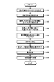
次に、基板洗浄装置1の具体的動作について図3を用いて説明する。図3は、第1の実施形態に係る基板洗浄処理の処理手順を示すフローチャートである。なお、基板洗浄処理が開始される前において、基板洗浄装置1は、図2に示す待機状態、すなわち、洗浄体11をウェハWに接触させていない状態にあるものとする。
Next, a specific operation of the substrate cleaning apparatus 1 will be described with reference to FIG. FIG. 3 is a flowchart illustrating a processing procedure of the substrate cleaning processing according to the first embodiment. It is assumed that the substrate cleaning apparatus 1 is in the standby state shown in FIG. 2, that is, the state where the cleaning
図3に示すように、制御装置4の制御部は、まず、第2荷重検知部40の出力値を取得する(ステップS101)。すなわち、制御部は、洗浄体ヘッド部10、第1荷重検知部20および第2ベース部材31の合計重量を取得する。なお、図2に示す待機状態においては、第2ベース部材31には、エアシリンダ33による浮力は働いていないものとする。
As shown in FIG. 3, the control part of the control apparatus 4 acquires the output value of the 2nd
また、制御部は、制御装置4の記憶部に記憶された接触圧の設定値を取得する(ステップS102)。接触圧の設定値は、ユーザによって予め設定される値であり、適宜変更可能である。 Further, the control unit acquires a set value of contact pressure stored in the storage unit of the control device 4 (step S102). The set value of the contact pressure is a value set in advance by the user and can be changed as appropriate.
つづいて、制御部は、ステップS101において取得した第2荷重検知部40の出力値と、ステップS102において取得した接触圧の設定値とに基づいて洗浄体ヘッド部10に与える浮力値を決定する(ステップS103)。具体的には、制御部は、第2荷重検知部40の出力値(すなわち、洗浄体ヘッド部10、第1荷重検知部20および第2ベース部材31の合計重量)と接触圧の設定値との差分を浮力値として決定する。
Subsequently, the control unit determines a buoyancy value to be given to the cleaning
そして、制御部は、決定した浮力値に従って電空レギュレータ60を制御する(ステップS104)。すなわち、ステップS103において決定した浮力値が得られるように、電空レギュレータ60からエアシリンダ33に供給されるエアの圧力を調整する。これにより、エアシリンダ33の昇降軸33bから第2ベース部材31に対して所望の浮力が与えられ、かかる浮力が第1荷重検知部20を介して洗浄体ヘッド部10へ伝わって、洗浄体ヘッド部10が所望の浮力で持ち上げられた状態となる。
Then, the control unit controls the
なお、ここでは、第2荷重検知部40の出力値を取得した後で、接触圧の設定値を取得することとしたが、出力値および設定値の取得順序は逆でもよい。
Here, after the output value of the
また、制御部は、第1荷重検知部20の出力値を取得し、取得した出力値をゼロリセットする(ステップS105)。すなわち、洗浄体11がウェハWに接触していない状態において洗浄体ヘッド部10から受ける荷重(つまり、洗浄体ヘッド部10の重量)をゼロに設定する。これにより、制御部は、後述する洗浄動作中において第1荷重検知部20から取得される値を反転することで、洗浄体11のウェハWへの接触圧を容易に検知することができる。
Moreover, a control part acquires the output value of the 1st
つづいて、制御部は、回転機構13(図2参照)を動作させて洗浄体11を回転させた後(ステップS106)、昇降機構50(図2参照)を用いて第3ベース部材34を所定位置まで降下させる(ステップS107)。ここで、かかるステップS107の動作について図4A,4Bを用いて具体的に説明する。図4Aおよび図4Bは、基板洗浄装置1の動作例を示す図である。
Subsequently, the control unit operates the rotating mechanism 13 (see FIG. 2) to rotate the cleaning body 11 (step S106), and then uses the lifting mechanism 50 (see FIG. 2) to move the
図4Aに示すように、制御部は、昇降機構50を用いて第3ベース部材34を降下させることによって、洗浄体11をウェハWの表面に接触させる。つづいて、制御部は、図4Bに示すように、第3ベース部材34をさらに2mm程度降下させて、第2ベース部材31を第2荷重検知部40から離隔させる。
As shown in FIG. 4A, the control unit lowers the
これにより、洗浄体ヘッド部10、第1荷重検知部20および第2ベース部材31が、エアシリンダ33の昇降軸33bとウェハWとによって支持された状態となる。言い換えれば、エアシリンダ33から受ける浮力およびウェハWから受ける抗力が、洗浄体ヘッド部10、第1荷重検知部20および第2ベース部材31の合計重量と釣り合った状態となる。このとき、ウェハWには、洗浄体ヘッド部10、第1荷重検知部20および第2ベース部材31の合計重量からエアシリンダ33の浮力を差し引いた力、すなわち、予め設定された所望の接触圧がかかっていることになる。
Accordingly, the cleaning
第1荷重検知部20が洗浄体ヘッド部10から受ける荷重は、上記接触圧の分だけ減少する。このため、第1荷重検知部20の出力値は、上記接触圧の分だけ小さくなる。したがって、制御部は、かかる出力値の変化量を洗浄体11のウェハWへの接触圧として検知することができる。しかも、ステップS105において第1荷重検知部20の出力値をゼロリセットしているため、接触圧の検知を容易に行うことができる。
The load that the first
なお、ここでは、ステップS105において第1荷重検知部20の出力値をゼロリセットする場合の例を示したが、制御部は、洗浄体11をウェハWへ接触させる前における第1荷重検知部20の出力値を記憶しておき、接触後における出力値との差分を求めることで、洗浄体11のウェハWへの接触圧を検知してもよい。
Here, an example in which the output value of the first
なお、制御部は、基板洗浄処理を開始してから洗浄体11がウェハWの表面に接触するまでのいずれかのタイミングで、基板保持装置2を制御することによってウェハWを回転させる。
The control unit rotates the wafer W by controlling the
図3に戻り、基板洗浄処理の内容についての説明を続ける。ステップS107の処理を終えると、制御部は、洗浄動作を開始する(ステップS108)。すなわち、制御部は、図1を用いて説明したように、移動機構55を用いて昇降機構50を移動させることによって、基板保持装置2によって回転するウェハWの表面全体をスクラブ洗浄する。制御部は、かかる洗浄動作中において、洗浄体11のウェハWへの接触圧を第1荷重検知部20を用いて検知する。
Returning to FIG. 3, the description of the contents of the substrate cleaning process will be continued. When the process of step S107 is completed, the control unit starts a cleaning operation (step S108). That is, as described with reference to FIG. 1, the control unit scrubs the entire surface of the wafer W rotated by the
ステップS108の洗浄動作を終えると、制御部は、初期位置(図1に示す位置)へ移動し(ステップS109)、基板保持装置2によるウェハWの回転を停止して、基板洗浄処理を終了する。
When the cleaning operation in step S108 is completed, the control unit moves to the initial position (position shown in FIG. 1) (step S109), stops the rotation of the wafer W by the
このように、第1の実施形態に係る基板洗浄装置1は、洗浄体ヘッド部10と浮力付与部30とを第1荷重検知部20で連結した構成とすることにより、洗浄動作中における洗浄体11のウェハWへの接触圧を検知することができる。
As described above, the substrate cleaning apparatus 1 according to the first embodiment has a configuration in which the cleaning
しかも、回転機構13が第1ベース部材14に一体的に保持されるため、ウェハWの凹凸によって洗浄体11が上下動した場合であっても、伝達ベルト13dが斜めになるといった事態が生じるおそれがなく、第1荷重検知部20を用いた接触圧の検知を正確に行うことができる。
In addition, since the
上述してきたように、第1の実施形態に係る基板洗浄装置1は、洗浄体ヘッド部10と、第1荷重検知部20と、浮力付与部30とを備える。洗浄体ヘッド部10は、洗浄体11と、洗浄体11を支持するシャフト12と、シャフト12を回転させる回転機構13と、これらを一体的に保持する第1ベース部材14とを備える。第1荷重検知部20は、一端側が洗浄体ヘッド部10の第1ベース部材14に連結され、洗浄体ヘッド部10から受ける荷重を検知する。浮力付与部30は、第1荷重検知部20の他端側に連結され、第1荷重検知部20を介して洗浄体ヘッド部10に浮力を与える。したがって、第1の実施形態に係る基板洗浄装置1によれば、洗浄体11のウェハWへの接触圧を正確に検知することができる。
As described above, the substrate cleaning apparatus 1 according to the first embodiment includes the cleaning
(第2の実施形態)
ところで、上述してきた第1の実施形態では、基板洗浄装置1が第2荷重検知部40を備え、かかる第2荷重検知部40の出力値に基づいて浮力値を決定することとしたが、基板洗浄装置は、必ずしも第2荷重検知部40を備えることを要しない。すなわち、基板洗浄装置は、第2荷重検知部40を用いることなく浮力値を決定することもできる。
(Second Embodiment)
In the first embodiment described above, the substrate cleaning apparatus 1 includes the second
以下では、かかる点について説明する。図5は、第2の実施形態に係る基板洗浄装置の構成を示す模式側面図である。なお、以下の説明では、既に説明した部分と同様の部分については、既に説明した部分と同一の符号を付し、重複する説明を省略する。 Hereinafter, this point will be described. FIG. 5 is a schematic side view showing the configuration of the substrate cleaning apparatus according to the second embodiment. In the following description, parts that are the same as those already described are given the same reference numerals as those already described, and redundant descriptions are omitted.
図5に示すように、第2の実施形態に係る基板洗浄装置1Aは、第1の実施形態に係る基板洗浄装置1から第2荷重検知部40および支持部材41を省いた構成を有する。また、第2の実施形態では、チャンバ3(図1参照)内にステージ70が設けられる。ステージ70は、水平面を有する部材である。ステージ70の水平面は、ウェハWの表面と同一の高さに配置されることが好ましい。
As shown in FIG. 5, the substrate cleaning apparatus 1 </ b> A according to the second embodiment has a configuration in which the second
次に、第2の実施形態に係る基板洗浄装置1Aが実行する浮力値決定処理の内容について図6を用いて説明する。図6は、第2の実施形態に係る浮力値決定処理の処理手順を示すフローチャートである。
Next, the content of the buoyancy value determination process executed by the
図6に示すように、制御部は、第1荷重検知部20の出力値を取得する(ステップS201)。すなわち、制御部は、洗浄体ヘッド部10の重量を取得する。また、制御部は、予め記憶された接触圧の設定値を取得する(ステップS202)。なお、第1の実施形態と同様、ステップS201およびステップS202の処理順序は、逆でもよい。
As illustrated in FIG. 6, the control unit acquires the output value of the first load detection unit 20 (step S201). That is, the control unit acquires the weight of the cleaning
つづいて、制御部は、第3ベース部材34を降下させることによって洗浄体11を降下させてステージ70の水平面に接触させる(ステップS203)。このとき、制御部は、第3ベース部材34を図4Bに示す位置、すなわち、洗浄動作中の位置まで降下させる。
Subsequently, the control unit lowers the cleaning
つづいて、制御部は、第1荷重検知部20の出力値を再度取得し(ステップS204)、ステップS201およびステップS204において取得した出力値と、ステップS202において取得した設定値とに基づいて浮力値を決定する(ステップS205)。具体的には、制御部は、まず、ステップS201において取得した出力値からステップS204において取得した出力値を差し引くことによって、洗浄体11のステージ70への接触圧を求める。そして、制御部は、求めた接触圧からステップS202において取得した接触圧の設定値を差し引くことによって浮力値を得ることができる。
Subsequently, the control unit acquires the output value of the first
なお、ステップS202の処理は、ステップS203の処理の後またはステップS204の処理の後に行ってもよい。 Note that the process of step S202 may be performed after the process of step S203 or after the process of step S204.
つづいて、制御部は、ステップS205において決定した浮力値に従って電空レギュレータ60を制御する(ステップS206)。これにより、第1の実施形態と同様に、洗浄体ヘッド部10が所望の浮力で持ち上げられた状態となる。
Subsequently, the control unit controls the
そして、制御部は、洗浄体11を上昇させた後(ステップS207)、第1荷重検知部20の出力値を取得し、取得した出力値をゼロリセットして(ステップS208)、浮力値決定処理を終了する。なお、制御部は、ステップS208の処理を終えた後、図3に示すステップS106〜ステップS109の処理を行う。また、制御部は、第1の実施形態と同様に、基板洗浄処理を開始してから洗浄体11がウェハWの表面に接触するまでのいずれかのタイミングで、基板保持装置2を制御することによってウェハWを回転させる。
Then, the control unit raises the cleaning body 11 (step S207), acquires the output value of the first
このように、制御部は、第2荷重検知部40を用いることなく、浮力値を決定することができる。
Thus, the control unit can determine the buoyancy value without using the second
ここでは、チャンバ3内に設置されたステージ70を用いて浮力値を決定することとしたが、かかるステージ70に相当する部材を基板洗浄装置に設けてもよい。かかる場合の例について図7を用いて説明する。図7は、第2の実施形態に係る基板洗浄装置の他の構成を示す模式側面図である。
Here, the buoyancy value is determined using the
図7に示すように、基板洗浄装置1Bは、洗浄体ヘッド部10に代えて洗浄体ヘッド部10Bを備える。
As shown in FIG. 7, the substrate cleaning apparatus 1 </ b> B includes a cleaning
洗浄体ヘッド部10Bは、洗浄体ヘッド部10が備える第1ベース部材14に代えて第1ベース部材14Bを備えており、第1ベース部材14Bは、当接部14dをさらに備える。当接部14dは、水平方向に延在する部材であり、たとえば支持部14bの上端部において第1連結部14cの反対側に設けられる。
The cleaning
また、基板洗浄装置1Bには、ヘッドサポート75と、支持部材76とが設けられる。ヘッドサポート75は、水平方向に延在する部材であり、洗浄体ヘッド部10Cの当接部14dの下側に配置される。かかるヘッドサポート75の一端側は、支持部材76に固定されており、他端側の上部は、当接部14dに対して接離可能である。
The
支持部材76は、ヘッドサポート75を所定の高さに支持する部材であり、第3ベース部材34の先端部に固定される。
The
上記のように構成された基板洗浄装置1Bにおいて、エアシリンダ33の浮力値は以下のようにして決定される。
In the
まず、制御部は、基板洗浄装置1Bの待機状態(洗浄体11がウェハWに接触しておらず、かつ、洗浄体ヘッド部10Bの当接部14dがヘッドサポート75に接触していない状態)における第1荷重検知部20の出力値(すなわち、洗浄体ヘッド部10Bの重量)を取得してゼロリセットしておく。
First, the control unit is in a standby state of the
つづいて、制御部は、エアシリンダ33の昇降軸33bを所定の高さまで降下させて、当接部14dをヘッドサポート75に接触させる。このとき、第1荷重検知部20の出力値は、ヘッドサポート75に加わる荷重(つまり、当接部14dのヘッドサポート75への接触圧)の分だけ減ることとなる。
Subsequently, the control unit lowers the elevating
制御部は、かかる出力値の差分が、制御装置4(図1参照)の記憶部に予め記憶された接触圧の設定値と一致するように、電空レギュレータ60から供給されるエアの圧力を調整する。これにより、浮力値が決定される。
The control unit adjusts the pressure of the air supplied from the
つづいて、制御部は、回転機構13を動作させて洗浄体11を回転させた後、昇降機構50を用いて第3ベース部材34を所定位置まで降下させて、ウェハWの表面に洗浄体11を接触させる。そして、制御部は、第3ベース部材34をさらに2mm程度降下させることによって、当接部14dをヘッドサポート75から離隔させる。これにより、ウェハWに対して所望の接触圧がかかった状態となる。なお、制御部は、基板洗浄処理を開始してから洗浄体11がウェハWの裏面に接触するまでのいずれかのタイミングで、基板保持装置2を制御することによってウェハWを回転させる。
Subsequently, the control unit operates the
そして、制御部は、洗浄動作中において第1荷重検知部20からの出力値を取得し、取得した出力値を反転させることで、洗浄体11のウェハWへの接触圧を検知することができる。
And a control part can detect the contact pressure to the wafer W of the cleaning
(第3の実施形態)
ところで、洗浄体の種類は、上述してきた各実施形態において示したものに限定されない。たとえば、上述してきた各実施形態では、ウェハWの表面を洗浄するタイプの洗浄体を用いる場合の例について説明したが、洗浄体は、ウェハWの裏面に接触してウェハWの裏面側の周縁部を洗浄するタイプのものであってもよい。以下では、かかる点について図8を用いて説明する。図8は、第3の実施形態に係る基板洗浄装置の構成を示す模式側面図である。
(Third embodiment)
By the way, the kind of cleaning body is not limited to what was shown in each embodiment mentioned above. For example, in each of the embodiments described above, an example in which a type of cleaning body that cleans the surface of the wafer W has been described. It may be of a type that cleans the part. Hereinafter, this point will be described with reference to FIG. FIG. 8 is a schematic side view showing the configuration of the substrate cleaning apparatus according to the third embodiment.
図8に示すように、第3の実施形態に係る基板洗浄装置1Cは、洗浄体ヘッド部10Bに代えて洗浄体ヘッド部10Cを備える。洗浄体ヘッド部10Cは、洗浄体ヘッド部10Bが備える洗浄体11に代えて、洗浄体11Cを備える。かかる洗浄体11Cは、たとえばベベルブラシであり、ウェハWの裏面に接触してウェハWの裏面側の周縁部を洗浄する。このような洗浄体11Cを用いた場合、上述してきた各実施形態とは逆向きの接触圧、すなわち、鉛直上向きの接触圧がウェハWにかかることとなる。なお、洗浄体ヘッド部10Cのその他の構成は、洗浄体ヘッド部10Bと同様である。
As shown in FIG. 8, a substrate cleaning apparatus 1C according to the third embodiment includes a cleaning
さらに、基板洗浄装置1Cは、第1の実施形態に係る基板洗浄装置1が備える第2荷重検知部40および支持部材41に代えて、第3荷重検知部80と支持部材81とを備える。支持部材81は、第3荷重検知部80を所定の高さに支持する部材であり、第3ベース部材34の先端部に固定される。
Furthermore, the substrate cleaning apparatus 1 </ b> C includes a third
第3荷重検知部80は、洗浄体11CのウェハWへの接触圧を所望の接触圧に設定するために用いられる検知部である。具体的には、第3荷重検知部80は、一端側の下部が支持部材81の上部に固定されるとともに、他端側の下部が洗浄体ヘッド部10Cの当接部14dに対して接離可能に設けられる。
The
上記のように構成された基板洗浄装置1Cにおいて、エアシリンダ33の浮力値は以下のようにして決定される。
In the substrate cleaning apparatus 1C configured as described above, the buoyancy value of the
まず、制御部は、基板洗浄装置1Cの待機状態(洗浄体11CがウェハWに接触しておらず、かつ、洗浄体ヘッド部10Cの当接部14dが第3荷重検知部80に接触していない状態)における第1荷重検知部20の出力値(すなわち、洗浄体ヘッド部10Cの重量)を取得してゼロリセットしておく。
First, the control unit waits for the substrate cleaning apparatus 1C (the cleaning body 11C is not in contact with the wafer W, and the
つづいて、制御部は、エアシリンダ33の昇降軸33bを所定の高さまで上昇させて、洗浄体ヘッド部10Cの当接部14dを第3荷重検知部80に接触させる。そして、制御部は、第3荷重検知部80の出力値(すなわち、エアシリンダ33の現在の浮力値)を取得する。
Subsequently, the control unit raises the elevating
つづいて、制御部は、第3荷重検知部80から取得される出力値が、制御装置4(図1参照)の記憶部に予め記憶された接触圧の設定値と一致するように、電空レギュレータ60から供給されるエアの圧力を調整する。これにより、浮力値が決定される。
Subsequently, the control unit performs electropneumatic so that the output value acquired from the third
つづいて、制御部は、回転機構13を動作させて洗浄体11Cを回転させた後、昇降機構50を用いて第3ベース部材34を所定位置まで上昇させて、ウェハWの裏面に洗浄体11Cを接触させる。そして、制御部は、第3ベース部材34をさらに2mm程度上昇させることによって、当接部14dを第3荷重検知部80から離隔させる。これにより、ウェハWに対して所望の接触圧がかかった状態となる。なお、制御部は、基板洗浄処理を開始してから洗浄体11CがウェハWの裏面に接触するまでのいずれかのタイミングで、基板保持装置2を制御することによってウェハWを回転させる。
Subsequently, the control unit operates the
そして、制御部は、洗浄動作中において第1荷重検知部20からの出力値を取得し、取得した出力値を反転させることで、洗浄体11CのウェハWへの接触圧を検知することができる。
And a control part can detect the contact pressure to the wafer W of the cleaning body 11C by acquiring the output value from the 1st
上述してきたように、ウェハWの裏面に接触してウェハWの裏面側の周縁部を洗浄する洗浄体11Cを用いた場合であっても、第1および第2の実施形態と同様に、洗浄動作中における洗浄体11CのウェハWへの接触圧を検知することができる。 As described above, even when the cleaning body 11C that contacts the back surface of the wafer W and cleans the peripheral edge of the back surface side of the wafer W is used, the cleaning is performed as in the first and second embodiments. The contact pressure of the cleaning body 11C on the wafer W during operation can be detected.
なお、ここでは、基板洗浄装置1Cに対して第3荷重検知部80および支持部材81を設け、第3荷重検知部80を用いてエアシリンダ33の浮力値を決定する場合の例を示したが、第2の実施形態と同様に、ステージを設け、かかるステージを用いてエアシリンダ33の浮力値を決定することとしてもよい。かかる場合、第3荷重検知部80および支持部材81は不要となる。また、図7に示す基板洗浄装置1Bと同様に、ヘッドサポートを用いてエアシリンダ33の浮力値を決定してもよい。かかる場合には、図8に示す第3荷重検知部80に代えてヘッドサポート75を設ければよい。
In addition, although the 3rd
また、上述してきた各実施形態では、エアシリンダ33の昇降軸33bが、第2ベース部材31に対して接離可能に構成される場合の例を示したが、昇降軸33bは、第2ベース部材31に対して固定されてもよい。このように構成すれば、昇降軸33bの上下動に対する洗浄体ヘッド部10,10B,10Cの追従性を高めることができる。
Moreover, in each embodiment mentioned above, although the example in case the raising / lowering axis |
また、上述してきた各実施形態では、洗浄体のウェハへの接触圧を検知する場合の例について説明してきたが、さらに、検知した接触圧に基づいて電空レギュレータ60のフィードバック制御を行うこととしてもよい。すなわち、制御部は、検知した接触圧と所望の接触圧との差分を求め、かかる差分が小さくなるように電空レギュレータ60が供給するエアの圧力(すなわち、浮力値)を変更するようにしてもよい。
Further, in each of the embodiments described above, an example in which the contact pressure of the cleaning body to the wafer has been described, but further, feedback control of the
さらなる効果や変形例は、当業者によって容易に導き出すことができる。このため、本発明のより広範な態様は、以上のように表しかつ記述した特定の詳細および代表的な実施形態に限定されるものではない。したがって、添付の特許請求の範囲およびその均等物によって定義される総括的な発明の概念の精神または範囲から逸脱することなく、様々な変更が可能である。 Further effects and modifications can be easily derived by those skilled in the art. Thus, the broader aspects of the present invention are not limited to the specific details and representative embodiments shown and described above. Accordingly, various modifications can be made without departing from the spirit or scope of the general inventive concept as defined by the appended claims and their equivalents.
W ウェハ
1 基板洗浄装置
2 基板保持装置
3 チャンバ
4 制御装置
10 洗浄体ヘッド部
11 洗浄体
12 シャフト
13 回転機構
13a モータ
13b 第1プーリ
13c 第2プーリ
13d 伝達ベルト
14 第1ベース部材
14c 第1連結部
20 第1荷重検知部
30 浮力付与部
31 第2ベース部材
31a 第2連結部
32 ガイド部
33 エアシリンダ
33b 昇降軸
34 第3ベース部材
40 第2荷重検知部
50 昇降機構
60 電空レギュレータ
W wafer 1
Claims (13)
一端側が前記洗浄体ヘッド部のベース部材に連結され、前記洗浄体ヘッド部から受ける荷重を検知する第1荷重検知部と、
前記第1荷重検知部を介して前記洗浄体ヘッド部に浮力を与える浮力付与部と
を備え、
前記浮力付与部は、
前記第1荷重検知部の他端側に連結される第2ベース部材と、
前記第2ベース部材を昇降可能に支持するガイド部と、
前記第2ベース部材を昇降させる昇降機構と、
前記昇降機構および前記ガイド部を保持する第3ベース部材と
を備えることを特徴とする基板洗浄装置。 A cleaning body, a shaft that supports the cleaning body, and a cleaning body head unit in which a rotation mechanism that rotates the shaft is integrally held by a base member;
A first load detection unit that is connected to a base member of the cleaning body head portion and that detects a load received from the cleaning body head portion;
And a buoyancy imparting unit that gives buoyancy to the cleaning member head portion through a pre-Symbol first load detection unit,
The buoyancy imparting unit is
A second base member connected to the other end side of the first load detector;
A guide portion that supports the second base member to be movable up and down;
An elevating mechanism for elevating and lowering the second base member;
A third base member for holding the lifting mechanism and the guide portion;
Substrate cleaning apparatus comprising: a.
前記第2ベース部材に対して接離可能であること
を特徴とする請求項1に記載の基板洗浄装置。 The lifting shaft of the lifting mechanism is
The substrate cleaning apparatus according to claim 1 , wherein the substrate cleaning apparatus is capable of contacting and separating from the second base member.
をさらに備えることを特徴とする請求項1または2に記載の基板洗浄装置。 The substrate cleaning apparatus according to claim 1 or 2, further comprising a second load detector for detecting the load received from said second base member.
前記第3ベース部材に保持され、かつ、前記第2ベース部材に対して接離可能であること
を特徴とする請求項3に記載の基板洗浄装置。 The second load detector is
The substrate cleaning apparatus according to claim 3 , wherein the substrate cleaning apparatus is held by the third base member and can be brought into contact with and separated from the second base member.
をさらに備えることを特徴とする請求項1〜4のいずれか一つに記載の基板洗浄装置。 The substrate cleaning apparatus according to any one of claims 1 to 4, further comprising a second lifting mechanism for lifting the third base member.
を特徴とする請求項1〜5のいずれか一つに記載の基板洗浄装置。 The first load detection unit, the substrate cleaning apparatus according to any one of claims 1-5, characterized in that the Roberval type load cell.
一端側の上面に前記洗浄体ヘッド部のベース部材が連結され、他端側の下面に前記浮力付与部が連結されること
を特徴とする請求項6に記載の基板洗浄装置。 The first load detector is
The substrate cleaning apparatus according to claim 6 , wherein a base member of the cleaning body head portion is connected to an upper surface on one end side, and the buoyancy imparting portion is connected to a lower surface on the other end side.
前記洗浄体ヘッド部のベース部材に連結され、前記洗浄体ヘッド部から受ける荷重を検知する第1荷重検知部と、 A first load detection unit connected to a base member of the cleaning body head unit and detecting a load received from the cleaning body head unit;
前記第1荷重検知部に連結され、前記第1荷重検知部を介して前記洗浄体ヘッド部に浮力を与える浮力付与部と A buoyancy imparting unit connected to the first load detection unit and imparting buoyancy to the cleaning body head unit via the first load detection unit;
を備え、 With
前記回転機構は、 The rotation mechanism is
モータと、 A motor,
前記モータの出力軸に取り付けられた第1プーリと、 A first pulley attached to the output shaft of the motor;
前記シャフトに取り付けられた第2プーリと、 A second pulley attached to the shaft;
前記第1プーリおよび前記第2プーリ間に掛け渡された伝達部材と A transmission member spanned between the first pulley and the second pulley;
を備えることを特徴とする基板洗浄装置。 A substrate cleaning apparatus comprising:
前記洗浄体ヘッド部のベース部材に連結され、前記洗浄体ヘッド部から受ける荷重を検知する第1荷重検知部と、 A first load detection unit connected to a base member of the cleaning body head unit and detecting a load received from the cleaning body head unit;
前記第1荷重検知部に連結され、前記第1荷重検知部を介して前記洗浄体ヘッド部に浮力を与える浮力付与部と A buoyancy imparting unit connected to the first load detection unit and imparting buoyancy to the cleaning body head unit via the first load detection unit;
を備え、 With
前記第1荷重検知部は、 The first load detector is
ロバーバル型のロードセルであり、一端側の上面に前記洗浄体ヘッド部のベース部材が連結され、他端側の下面に前記浮力付与部が連結されること It is a robust type load cell, the base member of the cleaning body head portion is connected to the upper surface on one end side, and the buoyancy imparting portion is connected to the lower surface on the other end side.
を特徴とする基板洗浄装置。 A substrate cleaning apparatus.
前記洗浄体ヘッド部のベース部材に連結され、前記洗浄体ヘッド部から受ける荷重を検知する第1荷重検知部と、 A first load detection unit connected to a base member of the cleaning body head unit and detecting a load received from the cleaning body head unit;
前記第1荷重検知部に連結され、前記第1荷重検知部を介して前記洗浄体ヘッド部に浮力を与える浮力付与部と A buoyancy imparting unit connected to the first load detection unit and imparting buoyancy to the cleaning body head unit via the first load detection unit;
を備え、 With
前記回転機構は、 The rotation mechanism is
モータと、 A motor,
前記モータの出力軸に取り付けられた第1プーリと、 A first pulley attached to the output shaft of the motor;
前記シャフトに取り付けられた第2プーリと、 A second pulley attached to the shaft;
前記第1プーリおよび前記第2プーリ間に掛け渡された伝達部材と A transmission member spanned between the first pulley and the second pulley;
を備え、 With
前記第1荷重検知部は、 The first load detector is
ロバーバル型のロードセルであり、一端側の上面に前記洗浄体ヘッド部のベース部材が連結され、他端側の下面に前記浮力付与部が連結されること It is a robust type load cell, the base member of the cleaning body head portion is connected to the upper surface on one end side, and the buoyancy imparting portion is connected to the lower surface on the other end side.
を特徴とする基板洗浄装置。 A substrate cleaning apparatus.
前記基板保持装置によって保持された前記基板を洗浄する基板洗浄装置と、
前記基板保持装置および前記基板洗浄装置を制御する制御部と
を備え、
前記基板洗浄装置は、
洗浄体、該洗浄体を支持するシャフトおよび該シャフトを回転させる回転機構がベース部材に一体的に保持された洗浄体ヘッド部と、
一端側が前記洗浄体ヘッド部のベース部材に連結され、前記洗浄体ヘッド部から受ける荷重を検知する第1荷重検知部と、
前記第1荷重検知部を介して前記洗浄体ヘッド部に浮力を与える浮力付与部と
を備え、
前記浮力付与部は、
前記第1荷重検知部の他端側に連結される第2ベース部材と、
前記第2ベース部材を昇降可能に支持するガイド部と、
前記第2ベース部材を昇降させる昇降機構と、
前記昇降機構および前記ガイド部を保持する第3ベース部材と
を備え、
前記基板洗浄装置は、
前記第2ベース部材から受ける荷重を検知する第2荷重検知部
を備えることを特徴とする基板洗浄ユニット。 A substrate holding device for rotatably holding the substrate;
A substrate cleaning device for cleaning the substrate held by the substrate holding device;
A controller that controls the substrate holding device and the substrate cleaning device,
The substrate cleaning apparatus includes:
A cleaning body, a shaft that supports the cleaning body, and a cleaning body head unit in which a rotation mechanism that rotates the shaft is integrally held by a base member;
A first load detection unit that is connected to a base member of the cleaning body head portion and that detects a load received from the cleaning body head portion;
And a buoyancy imparting unit that gives buoyancy to the cleaning member head portion through a pre-Symbol first load detection unit,
The buoyancy imparting unit is
A second base member connected to the other end side of the first load detector;
A guide portion that supports the second base member to be movable up and down;
An elevating mechanism for elevating and lowering the second base member;
A third base member for holding the lifting mechanism and the guide portion;
With
The substrate cleaning apparatus includes:
A second load detector for detecting a load received from the second base member
Substrate cleaning unit, characterized in that it comprises a.
前記第2荷重検知部の出力値に基づいて、前記浮力付与部が前記洗浄体ヘッド部に与える浮力を決定し、前記第1荷重検知部の出力値に基づいて、前記洗浄体の前記基板への接触圧を検知すること
を特徴とする請求項11に記載の基板洗浄ユニット。 The controller is
Based on the output value of the second load detection unit, the buoyancy imparted to the cleaning body head unit by the buoyancy applying unit is determined, and based on the output value of the first load detection unit, the substrate of the cleaning body The substrate cleaning unit according to claim 11, wherein the contact pressure is detected.
前記洗浄体を前記基板に接触させることにより前記基板を洗浄しているときに、前記第1荷重検知部の出力値に基づいて、前記洗浄体の前記基板への接触圧を検知すること
を特徴とする請求項11または12に記載の基板洗浄ユニット。 The controller is
When the substrate is being cleaned by bringing the cleaning body into contact with the substrate, the contact pressure of the cleaning body on the substrate is detected based on the output value of the first load detector. The substrate cleaning unit according to claim 11 or 12 .
Priority Applications (4)
| Application Number | Priority Date | Filing Date | Title |
|---|---|---|---|
| JP2012175266A JP5937456B2 (en) | 2012-08-07 | 2012-08-07 | Substrate cleaning device and substrate cleaning unit |
| US13/956,943 US9579695B2 (en) | 2012-08-07 | 2013-08-01 | Substrate cleaning apparatus and substrate cleaning unit |
| TW102128002A TW201420216A (en) | 2012-08-07 | 2013-08-05 | Substrate cleaning device and substrate cleaning unit |
| KR1020130093103A KR101761444B1 (en) | 2012-08-07 | 2013-08-06 | Substrate cleaning apparatus and substrate cleaning unit |
Applications Claiming Priority (1)
| Application Number | Priority Date | Filing Date | Title |
|---|---|---|---|
| JP2012175266A JP5937456B2 (en) | 2012-08-07 | 2012-08-07 | Substrate cleaning device and substrate cleaning unit |
Publications (3)
| Publication Number | Publication Date |
|---|---|
| JP2014036055A JP2014036055A (en) | 2014-02-24 |
| JP2014036055A5 JP2014036055A5 (en) | 2015-03-05 |
| JP5937456B2 true JP5937456B2 (en) | 2016-06-22 |
Family
ID=50065256
Family Applications (1)
| Application Number | Title | Priority Date | Filing Date |
|---|---|---|---|
| JP2012175266A Active JP5937456B2 (en) | 2012-08-07 | 2012-08-07 | Substrate cleaning device and substrate cleaning unit |
Country Status (4)
| Country | Link |
|---|---|
| US (1) | US9579695B2 (en) |
| JP (1) | JP5937456B2 (en) |
| KR (1) | KR101761444B1 (en) |
| TW (1) | TW201420216A (en) |
Families Citing this family (6)
| Publication number | Priority date | Publication date | Assignee | Title |
|---|---|---|---|---|
| JP2016131186A (en) * | 2015-01-13 | 2016-07-21 | 株式会社ディスコ | Spinner cleaning device |
| JP6941464B2 (en) * | 2017-04-07 | 2021-09-29 | 株式会社荏原製作所 | Substrate cleaning equipment and substrate processing equipment |
| JP6758247B2 (en) * | 2017-05-10 | 2020-09-23 | 株式会社荏原製作所 | Cleaning equipment and substrate processing equipment, cleaning equipment maintenance methods, and programs |
| CN107340128A (en) * | 2017-08-23 | 2017-11-10 | 长治清华机械厂 | Cleanninfg brushes experimental rig |
| CN109950170B (en) * | 2017-12-20 | 2023-04-04 | 弘塑科技股份有限公司 | Wafer cleaning equipment and method for controlling brush set of wafer cleaning equipment |
| KR20210144071A (en) | 2020-05-21 | 2021-11-30 | 삼성전자주식회사 | Substrate cleaning apparatus with tiltable roll brush |
Family Cites Families (11)
| Publication number | Priority date | Publication date | Assignee | Title |
|---|---|---|---|---|
| JP3328426B2 (en) | 1994-05-12 | 2002-09-24 | 東京エレクトロン株式会社 | Cleaning equipment |
| JP3539787B2 (en) | 1995-03-09 | 2004-07-07 | 大日本スクリーン製造株式会社 | Rotary substrate cleaning equipment |
| KR0175278B1 (en) * | 1996-02-13 | 1999-04-01 | 김광호 | Wafer Cleaner |
| JPH09326378A (en) * | 1996-06-05 | 1997-12-16 | Sony Corp | Method and equipment for cleaning substrate |
| US6292972B1 (en) * | 1998-03-30 | 2001-09-25 | Tokyo Electron Limited | Scrub washing apparatus and scrub washing method |
| JP3953716B2 (en) * | 2000-08-01 | 2007-08-08 | 株式会社荏原製作所 | Substrate cleaning device |
| JP4994074B2 (en) * | 2006-04-20 | 2012-08-08 | 東京エレクトロン株式会社 | Substrate cleaning apparatus, substrate cleaning method, substrate processing apparatus |
| JP4829710B2 (en) * | 2006-07-26 | 2011-12-07 | 芝浦メカトロニクス株式会社 | Substrate processing equipment |
| JP5413016B2 (en) * | 2008-07-31 | 2014-02-12 | 東京エレクトロン株式会社 | Substrate cleaning method, substrate cleaning apparatus and storage medium |
| CN102317744B (en) * | 2009-02-10 | 2013-09-04 | 株式会社岛津制作所 | Sensor mechanism body and electronic balance using the same |
| JP5583503B2 (en) * | 2010-07-14 | 2014-09-03 | 東京エレクトロン株式会社 | Substrate cleaning apparatus and coating and developing apparatus provided with the same |
-
2012
- 2012-08-07 JP JP2012175266A patent/JP5937456B2/en active Active
-
2013
- 2013-08-01 US US13/956,943 patent/US9579695B2/en active Active
- 2013-08-05 TW TW102128002A patent/TW201420216A/en unknown
- 2013-08-06 KR KR1020130093103A patent/KR101761444B1/en active IP Right Grant
Also Published As
| Publication number | Publication date |
|---|---|
| JP2014036055A (en) | 2014-02-24 |
| US20140041696A1 (en) | 2014-02-13 |
| KR101761444B1 (en) | 2017-07-25 |
| US9579695B2 (en) | 2017-02-28 |
| KR20140019755A (en) | 2014-02-17 |
| TWI559991B (en) | 2016-12-01 |
| TW201420216A (en) | 2014-06-01 |
Similar Documents
| Publication | Publication Date | Title |
|---|---|---|
| JP5937456B2 (en) | Substrate cleaning device and substrate cleaning unit | |
| KR102025600B1 (en) | Substrate cleaning apparatus and substrate processing apparatus | |
| KR101852365B1 (en) | Brush cleaning apparatus and control method therof | |
| JP2017528921A (en) | Semiconductor wafer cleaning apparatus and semiconductor wafer cleaning method | |
| JP5009253B2 (en) | Substrate cleaning device | |
| KR102238958B1 (en) | Load measuring apparatus and load measuring method | |
| WO2017018219A1 (en) | Substrate processing method and substrate processing device | |
| KR20170095748A (en) | Substrate cleaning apparatus and substrate processing apparatus | |
| JP2015005567A (en) | Substrate processing device | |
| CN110651356B (en) | Cleaning apparatus, substrate processing apparatus, maintenance method for cleaning apparatus, and computer-readable recording medium | |
| JP2020021863A (en) | Substrate processing method and substrate processing apparatus | |
| JP6011323B2 (en) | Substrate cleaning apparatus, substrate cleaning method, and storage medium | |
| JP6444277B2 (en) | Substrate processing apparatus and substrate processing method | |
| JP6785605B2 (en) | Substrate processing method, substrate processing equipment, and recording medium | |
| TWI786309B (en) | Substrate cleaning device and substrate cleaning method | |
| JP7133403B2 (en) | Substrate processing equipment | |
| KR102041310B1 (en) | Apparatus for treating a substrate and method for determining the state the pose of a substrate | |
| JP2018164037A (en) | Substrate processing method, substrate processing device, and program recording medium | |
| JP2024045835A (en) | Wafer Cleaning Equipment | |
| JP2010016156A (en) | Substrate cleaning device, substrate cleaning method, and storage medium | |
| KR20240035810A (en) | Polishing device and method for detecting polishing end point in the polishing device | |
| CN117352454A (en) | Detection device and detection method for electrostatic chuck | |
| KR20090011635A (en) | Spin scrubber |
Legal Events
| Date | Code | Title | Description |
|---|---|---|---|
| A521 | Request for written amendment filed |
Free format text: JAPANESE INTERMEDIATE CODE: A523 Effective date: 20150119 |
|
| A621 | Written request for application examination |
Free format text: JAPANESE INTERMEDIATE CODE: A621 Effective date: 20150119 |
|
| A977 | Report on retrieval |
Free format text: JAPANESE INTERMEDIATE CODE: A971007 Effective date: 20160203 |
|
| A131 | Notification of reasons for refusal |
Free format text: JAPANESE INTERMEDIATE CODE: A131 Effective date: 20160209 |
|
| A521 | Request for written amendment filed |
Free format text: JAPANESE INTERMEDIATE CODE: A523 Effective date: 20160329 |
|
| TRDD | Decision of grant or rejection written | ||
| A01 | Written decision to grant a patent or to grant a registration (utility model) |
Free format text: JAPANESE INTERMEDIATE CODE: A01 Effective date: 20160419 |
|
| A61 | First payment of annual fees (during grant procedure) |
Free format text: JAPANESE INTERMEDIATE CODE: A61 Effective date: 20160512 |
|
| R150 | Certificate of patent or registration of utility model |
Ref document number: 5937456 Country of ref document: JP Free format text: JAPANESE INTERMEDIATE CODE: R150 |
|
| R250 | Receipt of annual fees |
Free format text: JAPANESE INTERMEDIATE CODE: R250 |
|
| R250 | Receipt of annual fees |
Free format text: JAPANESE INTERMEDIATE CODE: R250 |
|
| R250 | Receipt of annual fees |
Free format text: JAPANESE INTERMEDIATE CODE: R250 |
|
| R250 | Receipt of annual fees |
Free format text: JAPANESE INTERMEDIATE CODE: R250 |
|
| R250 | Receipt of annual fees |
Free format text: JAPANESE INTERMEDIATE CODE: R250 |
|
| R250 | Receipt of annual fees |
Free format text: JAPANESE INTERMEDIATE CODE: R250 |