JP5935433B2 - Elevator fire operation system - Google Patents
Elevator fire operation system Download PDFInfo
- Publication number
- JP5935433B2 JP5935433B2 JP2012065735A JP2012065735A JP5935433B2 JP 5935433 B2 JP5935433 B2 JP 5935433B2 JP 2012065735 A JP2012065735 A JP 2012065735A JP 2012065735 A JP2012065735 A JP 2012065735A JP 5935433 B2 JP5935433 B2 JP 5935433B2
- Authority
- JP
- Japan
- Prior art keywords
- fire
- elevator
- floor
- output
- hoistway
- Prior art date
- Legal status (The legal status is an assumption and is not a legal conclusion. Google has not performed a legal analysis and makes no representation as to the accuracy of the status listed.)
- Active
Links
- 239000000779 smoke Substances 0.000 claims description 36
- 238000001514 detection method Methods 0.000 claims description 33
- 230000005856 abnormality Effects 0.000 claims description 26
- 230000002159 abnormal effect Effects 0.000 claims description 22
- 238000000034 method Methods 0.000 description 26
- 230000007704 transition Effects 0.000 description 8
- 238000012806 monitoring device Methods 0.000 description 6
- 238000010586 diagram Methods 0.000 description 5
- 230000007257 malfunction Effects 0.000 description 5
- 238000012544 monitoring process Methods 0.000 description 3
- 230000004913 activation Effects 0.000 description 2
- 238000012790 confirmation Methods 0.000 description 2
- 230000000694 effects Effects 0.000 description 2
- 230000002265 prevention Effects 0.000 description 2
- 230000002238 attenuated effect Effects 0.000 description 1
- 230000000903 blocking effect Effects 0.000 description 1
- 238000004891 communication Methods 0.000 description 1
- 230000008602 contraction Effects 0.000 description 1
- 239000004973 liquid crystal related substance Substances 0.000 description 1
- 238000012545 processing Methods 0.000 description 1
- 238000012546 transfer Methods 0.000 description 1
- 238000011179 visual inspection Methods 0.000 description 1
Images


Landscapes
- Maintenance And Inspection Apparatuses For Elevators (AREA)
Description
この発明は、エレベータの火災時運転システムに関するものである。 The present invention relates to an elevator operation system in a fire.
従来におけるエレベータの火災時運転システムにおいては、エレベータが停止する各階床に火災検知手段を設置し、火災発生時に火災発生階以外の階へ乗りかごを直行運転させた後、エレベータを休止させる火災時管制運転を実施するものが知られている(例えば、特許文献1参照)。また、火災発生時に乗りかごを火災時管制運転によって避難階に直行させ、この避難階で乗りかごを所定時間だけ戸開した後に強制的に戸閉した上で、エレベータを休止させるものも従来において知られている(例えば、特許文献2参照)。 In a conventional elevator operation system in the event of a fire, a fire detection means is installed on each floor where the elevator stops, and when the fire occurs, the elevator is stopped after directing the car to a floor other than the floor where the fire occurred. One that performs control operation is known (see, for example, Patent Document 1). Also, in the past, when a fire broke out, the car was moved directly to the evacuation floor by fire control operation, the elevator car was forcibly closed after opening the car for a predetermined time on this evacuation floor, and the elevator was suspended. It is known (see, for example, Patent Document 2).
さらに、発光素子と受光素子とを組み合わせて、発光素子より照射された光を遮蔽させて、その光量の変化によって受光素子より出力される受光信号のレベルで乗りかごの位置を検出する光電式のエレベータの位置検出装置において、受光信号のレベルが所定の短時間内で設定レベルまで変化したときに煙検出信号を出力し、この煙検出信号を受けて乗りかごの走行を阻止させるものも従来において知られている(例えば、特許文献3参照)。 In addition, a light-emitting element and a light-receiving element are combined to block the light emitted from the light-emitting element, and the position of the car is detected at the level of the light-receiving signal output from the light-receiving element by the change in the amount of light. Conventionally, an elevator position detection device that outputs a smoke detection signal when the level of a light reception signal changes to a set level within a predetermined short period of time and receives the smoke detection signal to prevent the car from traveling. It is known (see, for example, Patent Document 3).
しかしながら、特許文献1や特許文献2に示された従来におけるエレベータの火災時運転システムにおいては、エレベータが設置された建物内のある階床で火災発生が感知された場合には、エレベータの昇降路内に火炎や煙が侵入した状態であるか否かによらず、火災時管制運転へと移行してエレベータを休止させてしまう。
However, in the conventional elevator operation system shown in
このため、建物内のある階床での火災発生が感知はされたが、エレベータの昇降路内に火炎や煙はまだ侵入しておらず、エレベータの運転が可能であってエレベータを建物内の人の避難に使用することができる状況であっても、エレベータの運転は休止されてしまうためにその後の避難にエレベータを用いることができず、建物内滞在者の避難完了に要する時間が長くなってしまうという課題がある。 For this reason, the occurrence of a fire on a certain floor in the building was detected, but flames and smoke had not yet entered the elevator hoistway, and the elevator could be operated. Even in situations where people can be used for evacuation, the operation of the elevator will be suspended, so it will not be possible to use the elevator for subsequent evacuation, and the time required to complete the evacuation of residents staying in the building will increase. There is a problem that it ends up.
なお、エレベータの運転が休止され避難にエレベータを用いることができない場合には、非常階段等を用いて避難することとなるため、特に、車椅子利用者や高齢者の避難に要する時間が長くなってしまうおそれがある。 In addition, when the elevator operation is suspended and the elevator cannot be used for evacuation, the emergency stairs will be used to evacuate. There is a risk that.
また、特許文献3に示された従来のエレベータは、光電式のかご位置検出(着床)センサにおいて、受光信号のレベルが所定の短時間内で設定レベルまで変化したとき、すなわち、通常の乗りかご検出時とは異なる受光信号レベル変化があったときに、昇降路内の煙を検出したとして、エレベータの運転を休止させるものである。
Further, the conventional elevator shown in
しかし、通常の乗りかご検出時とは異なる受光信号レベル変化は、光電センサ自体の故障や直射日光等の要因による誤動作の場合でも起こり得る。したがって、受光信号レベルの変化をもって昇降内で煙が検出されたとしてかごの走行を阻止(エレベータの運転を休止)させてしまうと、必要以上にエレベータが休止されてしまいサービスの低下を招いてしまうという課題がある。 However, a change in the received light signal level that is different from that at the time of detecting a normal car can occur even in the case of malfunction due to factors such as failure of the photoelectric sensor itself or direct sunlight. Therefore, if smoke is detected in the elevator with a change in the light reception signal level and the car is prevented from traveling (elevator operation is suspended), the elevator will be suspended more than necessary, leading to a decrease in service. There is a problem.
この発明は、このような課題を解決するためになされたもので、エレベータが設置された建物内で火災発生が感知された場合に、エレベータの昇降路内の状態を考慮して、適切に火災時管制運転へと移行させることができるエレベータの火災時運転システムを得るものである。 The present invention has been made to solve such a problem, and when a fire occurrence is detected in a building where the elevator is installed, the fire is appropriately considered in consideration of the state in the elevator hoistway. An elevator fire operation system that can be shifted to time control operation is obtained.
この発明に係るエレベータの火災時運転システムにおいては、エレベータが設置される建物の各階床にそれぞれ設けられ、各階床での火災発生を感知して作動する火災報知器と、前記エレベータの昇降路内又は機械室内に設けられ前記昇降路内又は前記機械室内の高温異常を検出して異常信号を出力する温度センサ、及び、前記昇降路内のかごに設けられ発光部とこの発光部からの光を受光する受光部とを有しこの受光部における受光量の変化に基づいて異常信号を出力する光電センサからなる昇降路内異常検出手段と、前記火災報知器それぞれから出力された作動信号及び前記昇降路内異常検出手段から出力された異常信号に基づいて、前記エレベータを所定の火災時管制運転に移行させるか否かを判定する火災時管制運転判定手段と、を備え、前記火災時管制運転判定手段は、前記昇降路内異常検出手段から出力された異常信号が前記光電センサから出力されたものであった場合、前記火災報知器のいずれかから作動信号が出力され、かつ、巻上機又は調速機のエンコーダ出力より求めた前記かごの位置が所定の着床範囲外であるときに、前記エレベータを前記火災時管制運転に移行させるよう判定する構成とする。
In the elevator fire operation system according to the present invention, a fire alarm provided on each floor of the building where the elevator is installed, which operates by detecting the occurrence of a fire on each floor, and in the elevator hoistway Alternatively, a temperature sensor provided in a machine room for detecting a high temperature abnormality in the hoistway or in the machine room and outputting an abnormal signal, and a light emitting part provided in a car in the hoistway and light from the light emitting part a photoelectric sensor or Ranaru hoistway abnormality detecting means for outputting an abnormality signal based on a change in the amount of light received at the light receiving portion and a light-receiving unit for receiving, operating signals and output from each of the fire alarm A fire control operation determining means for determining whether to shift the elevator to a predetermined fire control operation based on an abnormality signal output from the hoistway abnormality detection means; For example, the FIRE control operation determining means, when the abnormality signal outputted from the hoistway abnormality detecting means was for output from the photoelectric sensor, the activation signal from one of the fire alarm output In addition, when the position of the car obtained from the encoder output of the hoisting machine or the speed governor is outside a predetermined landing range, the elevator is determined to shift to the fire control operation. .
この発明に係るエレベータの火災時運転システムにおいては、エレベータが設置された建物内で火災発生が感知された場合に、エレベータの昇降路内の状態を考慮して、適切に火災時管制運転へと移行させることができるという効果を奏する。 In the elevator fire operation system according to the present invention, when a fire occurrence is detected in the building where the elevator is installed, the state in the elevator hoistway is taken into consideration and the fire control operation is appropriately performed. There exists an effect that it can be made to shift.
この発明を添付の図面に従い説明する。各図を通じて同符号は同一部分又は相当部分を示しており、その重複説明は適宜に簡略化又は省略する。 The present invention will be described with reference to the accompanying drawings. Throughout the drawings, the same reference numerals indicate the same or corresponding parts, and redundant description thereof will be simplified or omitted as appropriate.
実施の形態1.
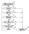
図1から図4は、この発明の実施の形態1に係るもので、図1はエレベータの火災時運転システムの全体構成を示すブロック図、図2はエレベータの火災時運転システムの火災時管制運転への移行条件を説明する図、図3はエレベータの火災時運転システムの運転モード変更動作を説明するフロー図、図4はエレベータの火災時運転システムの避難運転動作を説明するフロー図である。
FIGS. 1 to 4 relate to
図1において、1は、エレベータが設置される建物内に設けられた昇降路である。この昇降路1内には、エレベータのかご2が昇降自在に配設されている。かご2内には、このかご2内の乗客に対して種々の情報を報知するための表示器2a及びアナウンス機器2bが設置されている。表示器2aは、例えば、かご内操作盤に設けられた非常灯や液晶ディスプレイ(LCD)を用いることができる。また、アナウンス機器2bは、ブザーや音声アナウンスを鳴動するためのスピーカ等を備えている。
In FIG. 1, 1 is a hoistway provided in a building where an elevator is installed. An
エレベータの各号機には、かご2が停止階に対して正しく着床したか否かを確認するための着床装置3が設けられている。この着床装置3は、ここでは、磁気センサ3a及び光電センサ3bを備えている。磁気センサ3aは、エレベータのドアを開閉することができるドアゾーン内にかご2があるか否かを検出するためのものである。また、光電センサ3bは、主ロープの伸縮等によるかご2の着床位置のズレを補正するためのものである。
Each elevator unit is provided with a
着床装置3の磁気センサ3a及び光電センサ3bは、かご2側に設置される。そして、昇降路1内の各乗場側の所定の位置には、検出プレートが設置されている。磁気センサ3aは、磁気センサ3aと着床プレートとが係合して磁気回路の閉ループが形成されたか否かによって、かご2が停止階のドアゾーン内に停止したか否かを検出する。
The
光電センサ3bは、赤外光等の光を射出する発光部及びこの発光部に対向して配置され、発光部からの光を受光する受光部を備えている。かご2が所定のリレベルゾーン内に入ると、発光部と受光部との間に検出プレートが入り、発光部から射出した光が検出プレートにより遮光される。こうして生じる受光部における受光量の変化に基づいて、光電センサ3bはかご2がリレベルゾーン内にあるか否かを検出する。光電センサ3bから出力された信号は、各台制御装置6へと入力される。
The
昇降路1の頂部に設けられた機械室内(機械室がないエレベータにあっては昇降路1内)には、温度センサ4が設置されている。この温度センサ4は昇降路1内又は機械室内の雰囲気の温度を検出するためのものである。なお、温度センサ4を昇降路1内の機器や機械室内の制御盤内等に設け、これらの機器が正常な温度範囲で動作しているか否かを監視する目的を兼ねるようにしてもよい。温度センサ4から出力された温度検出信号は各台制御装置6へと入力される。
A temperature sensor 4 is installed in a machine room provided at the top of the hoistway 1 (in the
このシステムは、群管理装置5及びこの群管理装置5の下位装置である各台制御装置6を備えている。群管理装置5は1台以上のエレベータを一群として管理するためのものである。各台制御装置6は、1以上のエレベータの各号機毎に設けられており、群管理装置5による管理の下で、群を構成するエレベータの各号機それぞれの運転動作を制御するためのものである。
This system includes a
昇降路1の頂部に設けられた機械室内(機械室がないエレベータにあっては昇降路1内の頂部)には、昇降路1内や機械室内の煙を感知して作動する煙感知器7が設置されている。また、建物内の各階床(各階床にあるエレベータの乗場(ホール)を含む)には、設置された階床における火災の発生を検知して作動する火災報知器8(F1〜Fn:nは建物の階床数)が設置されている。
In a machine room (at the top of the
各階床の火災報知器8(F1〜Fn)の作動状態、押しボタン式の発振器(図示せず)の作動状態、及び、煙感知器7の作動状態は、このシステムが備える中央監視装置9の火災報知設備監視回路9aにおいて常時監視されている。
The operating state of the fire alarms 8 (F1 to Fn) on each floor, the operating state of the push button type oscillator (not shown), and the operating state of the
そして、各階床の火災報知器8(F1〜Fn)のいずれかが作動した場合には、火災報知器出力接点9bから群管理装置5へと火災報知器出力信号Feが出力される。また、煙感知器7が作動した場合には、煙感知器出力接点9cから群管理装置5へと煙感知器出力信号Seが出力される。さらに、監視員や管理員等が建物内での火災発生を目視等により発見した場合には、火災管制手動スイッチ9dを手動で操作することにより、火災管制手動スイッチ9dから群管理装置5へと火災管制スイッチ出力信号Fswが群管理装置5へと出力される。
When any of the fire alarms 8 (F1 to Fn) on each floor is activated, a fire alarm output signal Fe is output from the fire
群管理装置5には、火災時管制運転判定回路5aが備えられている。この火災時管制運転判定回路5aは、中央監視装置9からの火災報知器出力信号Fe、煙感知器出力信号Se及び火災管制スイッチ出力信号Fsw、並びに、各台制御装置6から一定周期で送信されてくる光電センサ3bの出力信号及び温度センサ4の出力信号に基づいて、エレベータの運転モードを判定するものである。この判定は、各信号出力に基づき、火災の発生場所とエレベータへの影響度に応じて、平常運転、火災時管制運転及び避難運転の3種類のうちから適切な運転モードを選択するものである。
The
図2は、火災時管制運転判定回路5aにおいて、火災時管制運転に移行する判定を行う条件を示すものである。まず、火災時管制運転判定回路5aでの判定に、光電センサ3bからの出力信号を用いない場合、図2(a)に示すように、火災時管制運転に移行すると判定する条件は以下のようになる。
FIG. 2 shows conditions for determining whether to shift to the fire control operation in the fire control
・火災報知器Fe接点出力があり、かつ、温度センサ4から昇降路内高温異常出力がある場合
又は、
・煙感知器7接点出力がある場合
又は、
・火災管制スイッチFsw出力がある場合
-When there is a fire alarm Fe contact output and there is a high temperature abnormal output in the hoistway from the temperature sensor 4, or
・ When there is a smoke sensor 7-contact output or
・ When there is a fire control switch Fsw output
また、火災時管制運転判定回路5aでの判定に、光電センサ3bからの出力信号を用いる場合、図2(b)に示すように、火災時管制運転に移行すると判定する条件は以下のようになる。
In addition, when the output signal from the
・火災報知器Fe接点出力があり、かつ、(温度センサ4から昇降路内高温異常出力がある、もしくは、光電センサ3bからの異常出力がある)場合
又は、
・煙感知器7接点出力がある場合
又は、
・火災管制スイッチFsw出力がある場合
-When there is a fire alarm Fe contact output and (there is a high temperature abnormal output in the hoistway from the temperature sensor 4 or an abnormal output from the
・ When there is a smoke sensor 7-contact output or
・ When there is a fire control switch Fsw output
ここで、図2(a)(b)において、火災報知器Fe接点出力とは、火災報知器8(F1〜Fn)からの各出力のOR(論理和)出力のことである。 Here, in FIGS. 2A and 2B, the fire alarm Fe contact output is an OR (logical sum) output of each output from the fire alarm 8 (F1 to Fn).
なお、前述したように、光電センサ3bからの出力信号は、まず、各台制御装置6へと入力された上で群管理装置5へと送られて火災時管制運転判定回路5aでの判定に用いられる。ここで、光電センサ3bの受光部における受光量が変化する要因としては、検出プレートによる遮光以外にも、火災等による昇降路1内の煙で発光部からの光が減光されることや、発光部/受光部の故障、直射日光による誤動作等も考えられる。
As described above, the output signal from the
そこで、光電センサ3bからの出力信号が変化し、すなわち、光電センサ3bの受光部における受光量に変化があった場合には、各台制御装置6は、まず、例えば巻上機や調速機のエンコーダ出力より求めたかご2の位置を確認し、かご2が所定のリレベルゾーン内にあるか否かを確認する。
Therefore, when the output signal from the
そして、かご2がリレベルゾーン内にない場合には、検出プレートによる遮光以外の要因を疑い、次に、火災報知器出力信号Fe及び火災管制スイッチ出力信号Fswの少なくともいずれかが出力されているか否かを確認する。そして、火災報知器出力信号Fe及び火災管制スイッチ出力信号Fswのいずれも出力されていない場合には、光電センサ3bの故障や誤検出であると判断し、当該光電センサ3bが設けられたエレベータのかご2を最寄階に停止させた後、当該エレベータの運転を休止する。
If the
また、温度センサ4から出力された温度検出信号が異常となる要因としては、火災の発生により昇降路1内/機械室内の温度が異常に上昇してしまうことの他、温度センサ4自体の故障や直射日光による誤作動等も考えられる。
In addition, the temperature detection signal output from the temperature sensor 4 may be abnormal because the temperature in the
そこで、温度センサ4から出力された温度検出信号が異常を示した場合には、各台制御装置6は、火災報知器出力信号Fe及び火災管制スイッチ出力信号Fswの少なくともいずれかが出力されているか否かを確認する。そして、火災報知器出力信号Fe及び火災管制スイッチ出力信号Fswのいずれも出力されていない場合には、温度センサ4の故障や誤検出であると判断し、当該光電センサ3bが設けられたエレベータのかご2を最寄階に停止させた後、当該エレベータの運転を休止する。
Therefore, when the temperature detection signal output from the temperature sensor 4 indicates an abnormality, each of the
したがって、結果的には、火災報知器出力信号Feや火災管制スイッチ出力信号Fswの出力がある場合に、光電センサ3bや温度センサ4からの異常出力が火災時管制運転判定回路5aにおける火災時管制運転への移行条件の判定に用いられることになる。
Therefore, as a result, when there is an output of the fire alarm output signal Fe or the fire control switch output signal Fsw, the abnormal output from the
次に、図3を参照しながら、以上に述べた火災時管制運転移行条件に従った、火災時管制運転判定回路5aにおける運転モード移行判定処理を説明する。なお、ここで、前述した図2(b)の光電センサ3bからの出力信号を用いる場合について説明する。
まず、ステップS1において、建物内の任意階すなわち1からnまでの階床のうちのいずれかの階で火災が発生すると、この火災発生を感知した火災報知器8(F1〜Fn)のいずれかが作動し、火災報知器出力信号Feが出力される。
Next, the operation mode transition determination process in the fire control
First, in step S1, when a fire occurs on any floor in the building, that is, one of
次に、ステップS2において、火災時管制運転判定回路5aは、火災管制手動スイッチ9dがONであるか(火災管制スイッチFsw出力があるか)否かを確認する。火災管制スイッチFsw出力があった場合には、ステップS8へと進み、火災時管制運転判定回路5aは火災時管制運転への移行を選択する。
Next, in step S2, the fire control
一方、火災管制スイッチFsw出力がない場合には、ステップS3へと進み、火災時管制運転判定回路5aは、煙感知器7が作動したか(煙感知器7接点出力があるか)否かを確認する。煙感知器7接点出力があった場合には、ステップS8へと進み、火災時管制運転判定回路5aは火災時管制運転への移行を選択する。
On the other hand, if there is no fire control switch Fsw output, the process proceeds to step S3, where the fire control
一方、煙感知器7接点出力がない場合には、ステップS4へと進み、火災時管制運転判定回路5aは、温度センサ4により検出された昇降路内温度が高温異常であるか(昇降路内高温異常出力があるか)否かを確認する。昇降路内高温異常出力があった場合には、ステップS8へと進み、火災時管制運転判定回路5aは火災時管制運転への移行を選択する。
On the other hand, if there is no
一方、昇降路内高温異常出力がない場合には、ステップS5へと進み、火災時管制運転判定回路5aは、かご2が着床範囲(リレベルゾーン)外で、光電センサ3bからの出力がOFFであるか(光電センサ3bからの異常出力があるか)否かを確認する。光電センサ3bからの異常出力があった場合には、ステップS8へと進み、火災時管制運転判定回路5aは火災時管制運転への移行を選択する。
On the other hand, if there is no high-temperature abnormal output in the hoistway, the process proceeds to step S5, and the fire control
一方、光電センサ3bからの異常出力がない場合(光電センサ3bからの出力がONで正常である場合)には、ステップS6を経てステップS7へと進み、火災時管制運転判定回路5aは避難運転への移行を選択することになる。ここで、ステップS7での避難運転に先立って、ステップS6において、各台制御装置6は、表示器2a及びアナウンス機器2bを用いて、かご2内に乗客に対して火災が発生した旨及び避難運転に移行する旨を報知する。
On the other hand, when there is no abnormal output from the
そして、ステップS7の後は、ステップS2へと戻り、火災時管制運転への移行条件が成立するまで、避難運転が継続される。 After step S7, the process returns to step S2, and the evacuation operation is continued until the condition for shifting to the fire-fighting control operation is satisfied.
このように、各階床に設置された火災報知器8(F1〜Fn)からの火災感知信号出力があった場合には、さらに、昇降路1内の光電センサ3b又は温度センサ4の異常を確認する。そして、光電センサ3bの異常出力により昇降路1内に煙の侵入が推認される場合や、温度センサ4の異常高温出力により昇降路1内が火炎等の侵入が予想される場合には、火災時管制運転へと移行し、光電センサ3bや温度センサ4の出力に異常がみられない場合には、昇降路1内は無事であってエレベータは利用可能であると判断して避難運転へと移行する。
As described above, when there is a fire detection signal output from the fire alarm 8 (F1 to Fn) installed on each floor, the abnormality of the
このため、火災が発生してもエレベータの機能が健全である間は、建物内の滞在者、特に車椅子利用者や高齢者等が、エレベータを有効に活用して避難することができ、迅速に避難を完了することができる。また、火災報知器8の作動のみでエレベータの全号機が火災時管制運転に移行して運転休止となることがないため、火災報知器8の誤作動や火災管制手動スイッチ9dの誤操作等によるサービス低下を防止することができる。
Therefore, as long as the elevator function is healthy even if a fire breaks out, residents in the building, especially wheelchair users and elderly people, can evacuate by using the elevator effectively. Evacuation can be completed. In addition, since all elevator units do not shift to fire-controlled operation only due to the operation of the
また、煙感知器7により昇降路1内で煙が感知された場合や、火災管制手動スイッチ9dが手動で操作された場合には、既にエレベータを避難に利用できる状態ではない可能性が高いと判断して、平常運転や避難運転から直ちに火災時管制運転へと移行する。このため、平常運転や避難運転中におけるかご2内の乗客の閉じ込めを防止することができる。
Further, when smoke is detected in the
群管理装置5は、火災時管制運転判定回路5aでの判定結果に基づいて、選択された運転モード(平常運転、避難運転、火災時管制運転)に従ってエレベータを運転させるよう各台制御装置6へと指示する。
Based on the determination result in the fire control
各台制御装置6には、群管理装置5により指示された運転モードに従ってエレベータを運転させるための平常運転回路6a、火災時管制運転回路6b及び避難運転回路6cを備えている。平常運転回路6aはエレベータを平常運転させるためのものである。
Each of the
火災時管制運転回路6bはエレベータを火災時管制運転させるためのものである。火災時管制運転においては、全ての号機のかご2がそれぞれの最寄階へと直行し、戸開してかご2内の乗客をかご2の外へと避難させた後、戸閉して運転休止となる。
The fire
避難運転回路6cはエレベータを避難運転させるためのものである。この避難運転回路6cによるエレベータの避難運転時の動作を、図4を参照しながら説明する。
まず、ステップS11において、群管理装置5から避難運転への移行が指示され避難運転を開始すると、次にステップS12において、予め設定登録された避難階へとかご2を直行させ、到着したらかご2を避難階に着床させる。
The
First, in step S11, when the shift to the evacuation operation is instructed from the
続くステップS13において、表示器2aとアナウンス機器2bを用いて、かご2内の乗客に対してこの避難階で降車するよう促す旨の報知を行う。そして、ステップS14へと進み、全ての乗客がかご2内から降車したか否かを確認する。かご2内から全ての乗客が降車するまではステップS13の報知とステップS14の確認を繰り返し、かご2内から全ての乗客が降車したことが確認できればステップS15へと進む。
In the subsequent step S13, the
ステップS15においては、現在かご2が停止している避難階以外の階床でのかご呼び、乗場呼びの登録があるか否かを確認する。そして、避難階以外の階床での呼びが登録されるまではステップS16へと進んで避難階にて停止待機を続け、避難階以外の階床での呼びが登録されるとステップS17へと進む。
In step S15, it is confirmed whether there is a registration of a car call or a hall call on a floor other than the evacuation floor where the
ステップS17においては、かご2を呼びが登録されている階床へと直行させ、かご2が呼び登録階に到着したらステップS18へと進む。ステップS18においては、呼び登録階で乗客をかご2に乗車させた後、避難階を行先として選択した呼びを自動的に登録する。このステップS18の後は、ステップS12へと戻り、避難階と呼び登録階との間でのピストン運行を繰り返す。
In step S17, the
なお、この避難運転時には、光電センサ3bから異常出力がなされ、光電センサ3bによりリレベルゾーン検出を正常に行うことができない状態である可能性も考えられる。しかし、このように光電センサ3bを用いることができない場合であっても、ドアゾーン検出用の磁気センサ3aの出力と巻上機や調速機のエンコーダ出力から求めたかご2の位置情報とを用いることで、避難階等にかご2を着床させること自体は可能である。
During this evacuation operation, there is a possibility that abnormal output is made from the
以上のように構成されたエレベータの火災時運転システムは、エレベータが設置される建物の各階床にそれぞれ設けられ、各階床での火災発生を感知して作動する火災報知器と、エレベータの昇降路内又は機械室内に設けられ昇降路内又は機械室内の高温異常を検出して異常信号を出力する温度センサ、及び、昇降路内のかごに設けられ発光部とこの発光部からの光を受光する受光部とを有しこの受光部における受光量の変化に基づいて異常信号を出力する光電センサの一方又は両方からなる昇降路内異常検出手段と、火災報知器それぞれから出力された作動信号及び昇降路内異常検出手段から出力された異常信号に基づいて、エレベータを所定の火災時管制運転に移行させるか否かを判定する火災時管制運転判定手段と、を備えたものである。このため、エレベータが設置された建物内で火災発生が感知された場合に、昇降路内の状態も考慮して、適切に火災時管制運転へと移行させることができる。 The elevator fire operating system configured as described above is provided on each floor of the building where the elevator is installed, and detects the fire occurrence on each floor, and operates the elevator hoistway. A temperature sensor provided in the machine room or in the machine room for detecting a high temperature abnormality in the hoistway or machine room and outputting an abnormal signal, and a light emitting part provided in a car in the hoistway and receiving light from the light emitting part An abnormality detection means in the hoistway composed of one or both of photoelectric sensors that have a light receiving portion and output an abnormal signal based on a change in the amount of light received by the light receiving portion; A fire control operation determination means for determining whether or not to shift the elevator to a predetermined fire control operation based on an abnormality signal output from the road abnormality detection means. . For this reason, when the occurrence of a fire is detected in a building where an elevator is installed, it is possible to appropriately shift to a fire-time control operation in consideration of the state in the hoistway.
実施の形態2.
図5から図8は、この発明の実施の形態2に係るもので、図5はエレベータの火災時運転システムの全体構成を示すブロック図、図6はエレベータの火災時運転システムの火災時管制運転への移行条件を説明する図、図7はエレベータの火災時運転システムの運転モード変更動作を説明するフロー図、図8はエレベータの火災時運転システムの避難運転動作を説明するフロー図である。
FIGS. 5 to 8 relate to
前述した実施の形態1では、避難運転における避難階は予め設定された階床となるため、火災が発生した階床、箇所によっては、必ずしも適切な階床を避難階とすることができるとは限らない。
In
そこで、ここで説明する実施の形態2は、前述した実施の形態1の構成において、各階床の火災報知器のうちの1つが火災を感知したが、2つ目の火災報知器の火災感知がなく(すなわち、1つの階床のみで火災発生が感知され)、かつ、光電センサや温度センサの異常出力もない場合に避難運転へと移行し、この避難運転においては火災が感知された階床以外の階床を避難階として選択するようにしたものである。 Therefore, in the second embodiment described here, in the configuration of the first embodiment described above, one of the fire alarms on each floor senses a fire, but the second fire alarm senses a fire. If there is no fire (detection of fire on only one floor) and there is no abnormal output from the photoelectric sensor or temperature sensor, the operation shifts to evacuation operation. In this evacuation operation, the floor where a fire is detected Other floors are selected as evacuation floors.
図5において、中央監視装置9の火災報知器出力接点9bからは、火災報知器8(F1〜Fn)の全ての作動状態を含む火災報知器状態信号Fswが出力される。そして、群管理装置5には、この火災報知器状態信号Fswに基づいて火災発生階を検出する火災発生階検出回路5bが備えられている。
In FIG. 5, the fire alarm state signal Fsw including all operating states of the fire alarm 8 (F1 to Fn) is output from the fire
この火災発生階検出回路5bは、火災報知器状態信号Fswに含まれる各階床の火災報知器8(F1〜Fn)の作動状態から、1番はじめに作動した火災報知器8(以下、これを火災報知器Fxという。F1≦Fx≦Fnである。)を検出して、この火災報知器Fxが設置されている階床を火災発生階とする。
This fire occurrence
また、群管理装置5の火災時管制運転判定回路5aは、中央監視装置9からの火災報知器状態信号Fst、煙感知器出力信号Se及び火災管制スイッチ出力信号Fsw、並びに、各台制御装置6から一定周期で送信されてくる光電センサ3bの出力信号及び温度センサ4の出力信号に基づいて、エレベータの運転モードを判定する。
In addition, the fire control
この火災時管制運転判定回路5aにおける火災時管制運転に移行する判定を行う条件を図6に示す。まず、火災時管制運転判定回路5aでの判定に、光電センサ3bからの出力信号を用いない場合は、図6(a)に示すように、火災時管制運転への移行を判定する条件は以下のようになる。
FIG. 6 shows conditions for performing the determination to shift to the fire control operation in the fire control
・火災報知器Fxの出力信号があり、かつ、(火災報知器Fyの出力信号がある、もしくは、温度センサ4から昇降路内高温異常出力がある)場合
又は、
・煙感知器7接点出力がある場合
又は、
・火災管制スイッチFsw出力がある場合
・ When there is an output signal of the fire alarm Fx and (there is an output signal of the fire alarm Fy, or there is a high temperature abnormal output in the hoistway from the temperature sensor 4) or
・ When there is a smoke sensor 7-contact output or
・ When there is a fire control switch Fsw output
また、火災時管制運転判定回路5aでの判定に、光電センサ3bからの出力信号を用いる場合は、図6(b)に示すように、火災時管制運転に移行すると判定する条件は以下のようになる。
Further, when the output signal from the
・火災報知器Fxの出力信号があり、かつ、(火災報知器Fyの出力信号がある、もしくは、温度センサ4から昇降路内高温異常出力がある、もしくは、光電センサ3bからの異常出力がある)場合
又は、
・煙感知器7接点出力がある場合
又は、
・火災管制スイッチFsw出力がある場合
There is an output signal of the fire alarm Fx, and (there is an output signal of the fire alarm Fy, there is a high temperature abnormal output in the hoistway from the temperature sensor 4, or there is an abnormal output from the photoelectric sensor 3b. ) Or
・ When there is a smoke sensor 7-contact output or
・ When there is a fire control switch Fsw output
ここで、これらの図6(a)(b)において、火災報知器Fxは、前述したように第1番目に作動した火災報知器8であり、F1≦Fx≦Fnである。そして、火災報知器Fyは、第2番目に作動した、すなわち、火災報知器Fxの次に作動した火災報知器8であり、F1≦Fy≦Fnである。また、火災報知器Fxと火災報知器Fyとは異なる階床に設置されており、Fx≠Fyである。
Here, in these FIG. 6 (a) (b), the fire alarm Fx is the
次に、図7を参照しながら、以上に述べた火災時管制運転移行条件に従った、火災時管制運転判定回路5aにおける運転モード移行判定処理を説明する。なお、ここで、前述した図6(b)の光電センサ3bからの出力信号を用いる場合について説明する。
Next, the operation mode transition determination processing in the fire control
また、この図7におけるステップS22は実施の形態1の図3のステップS2と同じである。さらに、図7のステップS23は図3のステップS3と、図7のステップS25は図3のステップS4と、図7のステップS26は図3のステップS5と、図7のステップS28は図3のステップS6と、図7のステップS30は図3のステップS8と、それぞれ同じである。そこで、これらのステップについてはその説明を省略する。 Further, step S22 in FIG. 7 is the same as step S2 in FIG. 3 of the first embodiment. Further, step S23 in FIG. 7 is step S3 in FIG. 3, step S25 in FIG. 7 is step S4 in FIG. 3, step S26 in FIG. 7 is step S5 in FIG. 3, and step S28 in FIG. Step S6 and step S30 in FIG. 7 are the same as step S8 in FIG. Therefore, description of these steps is omitted.
まず、ステップS21において、建物内のX階(1≦X≦n)で火災が発生すると、このX階に設置された火災報知器Fxが火災発生を感知して作動し、火災報知器Fxの作動信号を含む火災報知器状態信号Fstが出力される。この火災報知器Fxが第1番目の火災報知器である。 First, in step S21, when a fire occurs on the X floor (1 ≦ X ≦ n) in the building, the fire alarm Fx installed on the X floor senses the fire occurrence and operates. A fire alarm state signal Fst including an activation signal is output. This fire alarm Fx is the first fire alarm.
続くステップS22、S23を経て進んだステップS24においては、火災時管制運転判定回路5aは、火災報知器状態信号Fstに基づいて、第1番目の火災報知器Fxとは異なる第2番目の火災報知器Fyが作動したか否かを確認する。第2番目の火災報知器Fyが作動した場合には、ステップS30へと進み、火災時管制運転判定回路5aは火災時管制運転への移行を選択する。
In step S24 that has proceeded through subsequent steps S22 and S23, the fire control
一方、第2番目の火災報知器Fyが作動していない場合には、ステップS25へと進む。そして、ステップS25、S26を経てステップS27へと進んだ場合には、このステップS27において、群管理装置5は、第1番目に作動した火災報知器Fxが設置されているX階に対する呼び登録がある場合には当該呼び登録を無効にし、以後のX階に対する呼び登録を禁止する。
On the other hand, if the second fire alarm Fy is not activated, the process proceeds to step S25. And when it progresses to step S27 through step S25, S26, in this step S27, the
そして、ステップS28を経てステップS29へと進み、火災時管制運転判定回路5aは、X階の利用を除く避難運転への移行を選択する。このステップS29の後は、ステップS22へと戻り、火災時管制運転への移行条件が成立するまで、避難運転が継続される。
Then, the process proceeds to step S29 through step S28, and the fire control
このように、各階床に設置された火災報知器8(F1〜Fn)のうちの1つの火災報知器Fxが作動した場合には、さらに、昇降路1内の光電センサ3b又は温度センサ4の異常を確認する。そして、光電センサ3bの異常出力により昇降路1内に煙の侵入が推認される場合や、温度センサ4の異常高温出力により昇降路1内が火炎等の侵入が予想される場合には、火災時管制運転へと移行する。
Thus, when one fire alarm Fx of the fire alarms 8 (F1 to Fn) installed on each floor is activated, the
一方、光電センサ3bや温度センサ4の出力に異常がみられない場合には、昇降路1内は無事であってエレベータは利用可能であると判断して避難運転へと移行する。そして、この際の避難運転においては、火災発生階検出回路5bが検出した火災発生階、すなわち、第1番目に作動した火災報知器Fxが設置されているX階への呼び登録を禁止し、このX階以外の階を避難階にして、X階を利用しないようにする。したがって、火災報知器8から作動信号が出力された順序から特定した火災発生階以外の階を避難階にして、より適切かつ迅速な避難を支援することができる。
On the other hand, when there is no abnormality in the outputs of the
また、煙感知器7により昇降路1内で煙が感知された場合や、火災管制手動スイッチ9dが手動で操作された場合に加え、第1番目の火災報知器Fxとは異なる第2番目の火災報知器Fyが作動して2つの階床での火災が感知された場合には、平常運転や避難運転から直ちに火災時管制運転へと移行する。
Further, in addition to the case where smoke is detected in the
したがって、異なる2台の火災報知器8が作動した場合には、光電センサ3bや温度センサ4からの出力に異常がみられない場合であっても、エレベータの機能が完全である内に火災時管制運転へと移行することができる。
Therefore, when two
なお、ここでは、ステップS27において、X階に対する呼び登録がある場合には当該呼び登録を無効にし、以後のX階に対する呼び登録を禁止としたが、X階に滞在する者の避難を優先する場合には、かご2内から登録されたX階へのかご呼び登録は無効とするが、X階の乗場から登録されたX階への乗場呼びは有効とするようにしてもよい。
Here, in step S27, if there is a call registration for the X floor, the call registration is invalidated and the subsequent call registration for the X floor is prohibited. However, priority is given to evacuation of persons staying on the X floor. In this case, the car call registration from the
この場合には、ステップS29における避難運転は、「X階の利用を除く避難運転」ではなく、「X階からの乗場呼びを除きX階を利用しない避難運転」となる。ただし、X階の乗場において防火シャッターや防火ドア等の防火設備が設置されている場合には、X階での火災発生が感知されると防火設備が作動してX階の乗場が隔離された上で、中央監視装置9からの指令によりX階でのエレベータ利用は不可となるため、X階の乗場から登録されたX階への乗場呼びを有効することは無意味である。
In this case, the evacuation operation in step S29 is not “evacuation operation excluding use of the X floor” but “evacuation operation not using the X floor except for a hall call from the X floor”. However, if fire prevention equipment such as fire shutters and fire doors are installed at the X floor hall, the fire prevention equipment was activated when the fire on the X floor was detected, and the X floor hall was isolated. In the above, since the elevator on the X floor cannot be used by a command from the
次に、図7のステップS29におけるX階の利用を除く避難運転の動作について、図8を参照しながら説明する。なお、この実施の形態2においては、避難運転における避難階として優先順に第1の避難階及び第2の避難階の異なる2つの避難階が予め設定登録されている。 Next, the operation of the evacuation operation excluding the use of the X floor in step S29 in FIG. 7 will be described with reference to FIG. In the second embodiment, two evacuation floors, which are different from the first evacuation floor and the second evacuation floor, are preset and registered in order of priority as evacuation floors in the evacuation operation.
まず、ステップS41において、群管理装置5から避難運転への移行が指示され避難運転を開始すると、次にステップS42において、予め設定登録された第1の避難階が、火災発生が感知されたX階であるか否かを確認する。第1の避難階がX階であった場合には、ステップS43へと進み、予め設定登録された第2の避難階へとかご2を直行させ、到着したらかご2を第2の避難階に着床させる。
First, in step S41, when the shift to the evacuation operation is instructed from the
一方、第1の避難階がX階でなかった場合には、ステップS44へと進み、第1の避難階へとかご2を直行させ、到着したらかご2を第1の避難階に着床させる。ステップS43及びS44の後は、ステップS45へと進む。
On the other hand, if the first evacuation floor is not the X floor, the process proceeds to step S44, where the
このステップS45においては、表示器2aとアナウンス機器2bを用いて、かご2内の乗客に対して停止した避難階で降車するよう促す旨の報知を行う。そして、ステップS46へと進み、全ての乗客がかご2内から降車したか否かを確認する。かご2内から全ての乗客が降車するまではステップS45の報知とステップS46の確認を繰り返し、かご2内から全ての乗客が降車したことが確認できればステップS47へと進む。
In this step S45, the
ステップS47においては、現在かご2が停止している避難階及び火災発生階であるX階以外の階床でのかご呼び、乗場呼びの登録があるか否かを確認する。そして、避難階及びX階以外の階床での呼びが登録されるまではステップS48へと進んで避難階にて停止待機を続け、避難階及びX階以外の階床での呼びが登録されるとステップS49へと進む。
In step S47, it is confirmed whether there is registration of a car call and a hall call on floors other than the evacuation floor where the
ステップS49及びS50は、実施の形態1の図4におけるステップS17及びS18と同じであるためその説明を省略する。ステップS50の後は、ステップS42へと戻り、避難階と呼び登録階との間でのピストン運行を繰り返す。 Steps S49 and S50 are the same as steps S17 and S18 in FIG. After step S50, the process returns to step S42 to repeat the piston operation between the evacuation floor and the registered floor.
なお、図5においては、火災報知器状態信号Fstと煙感知器出力信号Seと火災管制スイッチ出力信号Fswとを別々に図示しているが、これらの信号データに係る通信を適宜にまとめて行うようにしてもよい。例えば、火災報知器状態信号Fstと煙感知器出力信号Seとを一緒にして送信したり、火災報知器状態信号Fstと火災管制スイッチ出力信号Fswとを一緒に送信したり、又は、これらの信号全てを一緒に送信したりというごとくである。あるいは、火災報知器出力接点9bの接点数に余裕があるのであれば、火災報知器8(F1〜Fn)の全ての出力信号を並列にして群管理装置5へと送信するようにしてもよい。
他の構成については実施の形態1と同様であって、その詳細説明は省略する。
In FIG. 5, the fire alarm state signal Fst, the smoke detector output signal Se, and the fire control switch output signal Fsw are illustrated separately, but communication related to these signal data is performed as appropriate. You may do it. For example, the fire alarm state signal Fst and the smoke detector output signal Se are transmitted together, the fire alarm state signal Fst and the fire control switch output signal Fsw are transmitted together, or these signals Like sending everything together. Alternatively, if there is a margin in the number of contacts of the fire
Other configurations are the same as those of the first embodiment, and detailed description thereof is omitted.
以上のように構成されたエレベータの火災時運転システムは、実施の形態1の構成において、火災報知器から作動信号が出力された順序に基づいて、建物の各階床のうち火災が発生した火災発生階を検出する火災発生階検出手段を備え、避難運転における避難階を火災発生階検出手段により検出された火災発生階以外の階床とする。また、複数の火災報知器から作動信号が出力された場合には、エレベータを火災時管制運転に移行させるものである。 The elevator fire operating system configured as described above is the fire occurrence in which fire has occurred in each floor of the building based on the order in which the operation signals are output from the fire alarm in the configuration of the first embodiment. Fire detection floor detection means for detecting the floor is provided, and the evacuation floor in the evacuation operation is a floor other than the fire occurrence floor detected by the fire generation floor detection means. Moreover, when an operation signal is output from a plurality of fire alarms, the elevator is shifted to a fire control operation.
このため、実施の形態1と同様の効果を奏することができるのに加えて、火災発生時にさらに適切な運転モード変更を実施することができる。 For this reason, in addition to having the same effects as those of the first embodiment, it is possible to further appropriately change the operation mode when a fire occurs.
1 昇降路
2 かご
2a 表示器
2b アナウンス機器
3 着床装置
3a 磁気センサ
3b 光電センサ
4 温度センサ
5 群管理装置
5a 火災時管制運転判定回路
5b 火災発生階検出回路
6 各台制御装置
6a 平常運転回路
6b 火災時管制運転回路
6c 避難運転回路
7 煙感知器
8 火災報知器
9 中央監視装置
9a 火災報知設備監視回路
9b 火災報知器出力接点
9c 煙感知器出力接点
9d 火災管制手動スイッチ
DESCRIPTION OF
Claims (6)
前記エレベータの昇降路内又は機械室内に設けられ前記昇降路内又は前記機械室内の高温異常を検出して異常信号を出力する温度センサ、及び、前記昇降路内のかごに設けられ発光部とこの発光部からの光を受光する受光部とを有しこの受光部における受光量の変化に基づいて異常信号を出力する光電センサからなる昇降路内異常検出手段と、
前記火災報知器それぞれから出力された作動信号及び前記昇降路内異常検出手段から出力された異常信号に基づいて、前記エレベータを所定の火災時管制運転に移行させるか否かを判定する火災時管制運転判定手段と、を備え、
前記火災時管制運転判定手段は、前記昇降路内異常検出手段から出力された異常信号が前記光電センサから出力されたものであった場合、前記火災報知器のいずれかから作動信号が出力され、かつ、巻上機又は調速機のエンコーダ出力より求めた前記かごの位置が所定の着床範囲外であるときに、前記エレベータを前記火災時管制運転に移行させるよう判定することを特徴とするエレベータの火災時運転システム。 A fire alarm provided on each floor of the building where the elevator is installed, and activated by detecting the occurrence of a fire on each floor;
A temperature sensor provided in a hoistway of the elevator or in a machine room for detecting a high temperature abnormality in the hoistway or the machine room and outputting an abnormal signal; and a light emitting unit provided in a car in the hoistway a photoelectric sensor or Ranaru hoistway abnormality detecting means for outputting an abnormality signal based on a change in the amount of light received at the light receiving portion and a light receiving portion for receiving light from the light emitting portion,
Fire control that determines whether or not to shift the elevator to a predetermined fire control operation based on the operation signal output from each of the fire alarms and the abnormality signal output from the hoistway abnormality detection means Driving determination means ,
The fire control operation determining means, when the abnormality signal output from the hoistway abnormality detection means is output from the photoelectric sensor, an operation signal is output from any of the fire alarms, In addition, when the position of the car obtained from the encoder output of the hoisting machine or the governor is out of a predetermined landing range, it is determined to shift the elevator to the fire control operation. Elevator fire operation system.
前記火災時管制運転判定手段は、前記煙感知器から作動信号が出力された場合に、前記エレベータを前記火災時管制運転に移行させるよう判定することを特徴とする請求項1に記載のエレベータの火災時運転システム。 A smoke detector that is provided at the top of the hoistway or in the machine room and operates by sensing smoke;
2. The elevator control operation according to claim 1, wherein the fire control operation determination unit determines to shift the elevator to the fire control operation when an operation signal is output from the smoke detector. 3. Fire driving system.
前記避難運転における避難階は、前記火災発生階検出手段により検出された前記火災発生階以外の階床とすることを特徴とする請求項4に記載のエレベータの火災時運転システム。 Based on the order in which the operation signal is output from the fire alarm, comprising a fire occurrence floor detection means for detecting a fire occurrence floor where a fire has occurred among the floors of the building,
The elevator operation system according to claim 4 , wherein the evacuation floor in the evacuation operation is a floor other than the fire occurrence floor detected by the fire occurrence floor detection means.
Priority Applications (1)
| Application Number | Priority Date | Filing Date | Title |
|---|---|---|---|
| JP2012065735A JP5935433B2 (en) | 2012-03-22 | 2012-03-22 | Elevator fire operation system |
Applications Claiming Priority (1)
| Application Number | Priority Date | Filing Date | Title |
|---|---|---|---|
| JP2012065735A JP5935433B2 (en) | 2012-03-22 | 2012-03-22 | Elevator fire operation system |
Publications (3)
| Publication Number | Publication Date |
|---|---|
| JP2013193867A JP2013193867A (en) | 2013-09-30 |
| JP2013193867A5 JP2013193867A5 (en) | 2015-03-05 |
| JP5935433B2 true JP5935433B2 (en) | 2016-06-15 |
Family
ID=49393277
Family Applications (1)
| Application Number | Title | Priority Date | Filing Date |
|---|---|---|---|
| JP2012065735A Active JP5935433B2 (en) | 2012-03-22 | 2012-03-22 | Elevator fire operation system |
Country Status (1)
| Country | Link |
|---|---|
| JP (1) | JP5935433B2 (en) |
Families Citing this family (2)
| Publication number | Priority date | Publication date | Assignee | Title |
|---|---|---|---|---|
| CN107285153A (en) * | 2017-07-31 | 2017-10-24 | 合肥桥旭科技有限公司 | A kind of elevator management control system based on Internet of Things |
| CN107473042A (en) * | 2017-08-16 | 2017-12-15 | 西子电梯集团有限公司 | A kind of fireman's switch control system for elevator |
Family Cites Families (4)
| Publication number | Priority date | Publication date | Assignee | Title |
|---|---|---|---|---|
| JPS53120060U (en) * | 1977-03-02 | 1978-09-25 | ||
| JPH01150685A (en) * | 1987-12-07 | 1989-06-13 | Mitsubishi Electric Corp | Position transducer for elevator |
| JPH05147849A (en) * | 1991-11-26 | 1993-06-15 | Toshiba Corp | Elevator controller |
| JP5660594B2 (en) * | 2009-12-15 | 2015-01-28 | 東芝エレベータ株式会社 | Elevator operation control device |
-
2012
- 2012-03-22 JP JP2012065735A patent/JP5935433B2/en active Active
Also Published As
| Publication number | Publication date |
|---|---|
| JP2013193867A (en) | 2013-09-30 |
Similar Documents
| Publication | Publication Date | Title |
|---|---|---|
| EP1988048B1 (en) | Evacuation assistance device for elevator | |
| JP4937762B2 (en) | Elevator evacuation support device | |
| US8113320B2 (en) | Fire evacuation support system and fire door control device | |
| JP4932855B2 (en) | Elevator control system | |
| CN102381604B (en) | Elevator device | |
| CN112135787B (en) | Safety switching system and method for switching an elevator installation between a normal operating mode and an inspection operating mode | |
| KR101305568B1 (en) | Notification device of elevator | |
| WO2011125164A1 (en) | Control device for elevator | |
| US20210261383A1 (en) | Elevator monitoring system | |
| JP2011046494A (en) | Elevator control device | |
| JP5935433B2 (en) | Elevator fire operation system | |
| JP5704685B2 (en) | Evacuation system for elevator | |
| JP5392354B2 (en) | Elevator control device | |
| KR102348615B1 (en) | elevator system | |
| KR100919548B1 (en) | Elevator control apparatus and control method | |
| JP4932399B2 (en) | Elevator rescue operation device | |
| JP2004359405A (en) | Remote rescue method for elevator in case of earthquake | |
| JP2010024024A (en) | Earthquake control preferential communication system | |
| JP2000351545A (en) | Elevator maintenance safety device | |
| JP2011098799A (en) | Notification device of elevator | |
| JP5003060B2 (en) | Elevator earthquake rescue operation method | |
| JP2008162799A (en) | Elevator control device | |
| JP4180878B2 (en) | Elevator fire operation device | |
| FI118730B (en) | Method and equipment for evacuating a building or part thereof | |
| JPH04345490A (en) | Emergency operation device of elevator |
Legal Events
| Date | Code | Title | Description |
|---|---|---|---|
| A621 | Written request for application examination |
Free format text: JAPANESE INTERMEDIATE CODE: A621 Effective date: 20150107 |
|
| A521 | Request for written amendment filed |
Free format text: JAPANESE INTERMEDIATE CODE: A523 Effective date: 20150114 |
|
| A977 | Report on retrieval |
Free format text: JAPANESE INTERMEDIATE CODE: A971007 Effective date: 20151120 |
|
| A131 | Notification of reasons for refusal |
Free format text: JAPANESE INTERMEDIATE CODE: A131 Effective date: 20151201 |
|
| A521 | Request for written amendment filed |
Free format text: JAPANESE INTERMEDIATE CODE: A523 Effective date: 20160121 |
|
| TRDD | Decision of grant or rejection written | ||
| A01 | Written decision to grant a patent or to grant a registration (utility model) |
Free format text: JAPANESE INTERMEDIATE CODE: A01 Effective date: 20160412 |
|
| A61 | First payment of annual fees (during grant procedure) |
Free format text: JAPANESE INTERMEDIATE CODE: A61 Effective date: 20160425 |
|
| R150 | Certificate of patent or registration of utility model |
Ref document number: 5935433 Country of ref document: JP Free format text: JAPANESE INTERMEDIATE CODE: R150 |
|
| R250 | Receipt of annual fees |
Free format text: JAPANESE INTERMEDIATE CODE: R250 |
|
| R250 | Receipt of annual fees |
Free format text: JAPANESE INTERMEDIATE CODE: R250 |
|
| R250 | Receipt of annual fees |
Free format text: JAPANESE INTERMEDIATE CODE: R250 |
|
| R250 | Receipt of annual fees |
Free format text: JAPANESE INTERMEDIATE CODE: R250 |
|
| R250 | Receipt of annual fees |
Free format text: JAPANESE INTERMEDIATE CODE: R250 |
|
| R250 | Receipt of annual fees |
Free format text: JAPANESE INTERMEDIATE CODE: R250 |