JP5927083B2 - Dressing process monitoring method and polishing apparatus - Google Patents
Dressing process monitoring method and polishing apparatus Download PDFInfo
- Publication number
- JP5927083B2 JP5927083B2 JP2012187383A JP2012187383A JP5927083B2 JP 5927083 B2 JP5927083 B2 JP 5927083B2 JP 2012187383 A JP2012187383 A JP 2012187383A JP 2012187383 A JP2012187383 A JP 2012187383A JP 5927083 B2 JP5927083 B2 JP 5927083B2
- Authority
- JP
- Japan
- Prior art keywords
- dresser
- polishing
- polishing pad
- work coefficient
- dressing
- Prior art date
- Legal status (The legal status is an assumption and is not a legal conclusion. Google has not performed a legal analysis and makes no representation as to the accuracy of the status listed.)
- Active
Links
- 238000005498 polishing Methods 0.000 title claims description 320
- 238000000034 method Methods 0.000 title claims description 31
- 238000012544 monitoring process Methods 0.000 title claims description 9
- 238000012806 monitoring device Methods 0.000 claims description 42
- 230000005856 abnormality Effects 0.000 claims description 8
- 230000002159 abnormal effect Effects 0.000 description 13
- 238000010586 diagram Methods 0.000 description 8
- 239000007788 liquid Substances 0.000 description 8
- 238000006243 chemical reaction Methods 0.000 description 6
- 239000000758 substrate Substances 0.000 description 4
- 230000003750 conditioning effect Effects 0.000 description 3
- 230000007423 decrease Effects 0.000 description 3
- 229910003460 diamond Inorganic materials 0.000 description 2
- 239000010432 diamond Substances 0.000 description 2
- 239000002245 particle Substances 0.000 description 2
- 239000006061 abrasive grain Substances 0.000 description 1
- 239000012141 concentrate Substances 0.000 description 1
- 230000001186 cumulative effect Effects 0.000 description 1
- 238000013461 design Methods 0.000 description 1
- 238000011156 evaluation Methods 0.000 description 1
- 230000007774 longterm Effects 0.000 description 1
- 238000005259 measurement Methods 0.000 description 1
- 230000001172 regenerating effect Effects 0.000 description 1
- 238000007790 scraping Methods 0.000 description 1
- XLYOFNOQVPJJNP-UHFFFAOYSA-N water Substances O XLYOFNOQVPJJNP-UHFFFAOYSA-N 0.000 description 1
Images


Classifications
-
- B—PERFORMING OPERATIONS; TRANSPORTING
- B24—GRINDING; POLISHING
- B24B—MACHINES, DEVICES, OR PROCESSES FOR GRINDING OR POLISHING; DRESSING OR CONDITIONING OF ABRADING SURFACES; FEEDING OF GRINDING, POLISHING, OR LAPPING AGENTS
- B24B49/00—Measuring or gauging equipment for controlling the feed movement of the grinding tool or work; Arrangements of indicating or measuring equipment, e.g. for indicating the start of the grinding operation
- B24B49/18—Measuring or gauging equipment for controlling the feed movement of the grinding tool or work; Arrangements of indicating or measuring equipment, e.g. for indicating the start of the grinding operation taking regard of the presence of dressing tools
- B24B49/186—Measuring or gauging equipment for controlling the feed movement of the grinding tool or work; Arrangements of indicating or measuring equipment, e.g. for indicating the start of the grinding operation taking regard of the presence of dressing tools taking regard of the wear of the dressing tools
-
- B—PERFORMING OPERATIONS; TRANSPORTING
- B24—GRINDING; POLISHING
- B24B—MACHINES, DEVICES, OR PROCESSES FOR GRINDING OR POLISHING; DRESSING OR CONDITIONING OF ABRADING SURFACES; FEEDING OF GRINDING, POLISHING, OR LAPPING AGENTS
- B24B49/00—Measuring or gauging equipment for controlling the feed movement of the grinding tool or work; Arrangements of indicating or measuring equipment, e.g. for indicating the start of the grinding operation
- B24B49/18—Measuring or gauging equipment for controlling the feed movement of the grinding tool or work; Arrangements of indicating or measuring equipment, e.g. for indicating the start of the grinding operation taking regard of the presence of dressing tools
-
- B—PERFORMING OPERATIONS; TRANSPORTING
- B24—GRINDING; POLISHING
- B24B—MACHINES, DEVICES, OR PROCESSES FOR GRINDING OR POLISHING; DRESSING OR CONDITIONING OF ABRADING SURFACES; FEEDING OF GRINDING, POLISHING, OR LAPPING AGENTS
- B24B53/00—Devices or means for dressing or conditioning abrasive surfaces
- B24B53/017—Devices or means for dressing, cleaning or otherwise conditioning lapping tools
-
- B—PERFORMING OPERATIONS; TRANSPORTING
- B24—GRINDING; POLISHING
- B24B—MACHINES, DEVICES, OR PROCESSES FOR GRINDING OR POLISHING; DRESSING OR CONDITIONING OF ABRADING SURFACES; FEEDING OF GRINDING, POLISHING, OR LAPPING AGENTS
- B24B37/00—Lapping machines or devices; Accessories
-
- B—PERFORMING OPERATIONS; TRANSPORTING
- B24—GRINDING; POLISHING
- B24B—MACHINES, DEVICES, OR PROCESSES FOR GRINDING OR POLISHING; DRESSING OR CONDITIONING OF ABRADING SURFACES; FEEDING OF GRINDING, POLISHING, OR LAPPING AGENTS
- B24B49/00—Measuring or gauging equipment for controlling the feed movement of the grinding tool or work; Arrangements of indicating or measuring equipment, e.g. for indicating the start of the grinding operation
- B24B49/006—Measuring or gauging equipment for controlling the feed movement of the grinding tool or work; Arrangements of indicating or measuring equipment, e.g. for indicating the start of the grinding operation taking regard of the speed
-
- B—PERFORMING OPERATIONS; TRANSPORTING
- B24—GRINDING; POLISHING
- B24B—MACHINES, DEVICES, OR PROCESSES FOR GRINDING OR POLISHING; DRESSING OR CONDITIONING OF ABRADING SURFACES; FEEDING OF GRINDING, POLISHING, OR LAPPING AGENTS
- B24B49/00—Measuring or gauging equipment for controlling the feed movement of the grinding tool or work; Arrangements of indicating or measuring equipment, e.g. for indicating the start of the grinding operation
- B24B49/10—Measuring or gauging equipment for controlling the feed movement of the grinding tool or work; Arrangements of indicating or measuring equipment, e.g. for indicating the start of the grinding operation involving electrical means
-
- B—PERFORMING OPERATIONS; TRANSPORTING
- B24—GRINDING; POLISHING
- B24B—MACHINES, DEVICES, OR PROCESSES FOR GRINDING OR POLISHING; DRESSING OR CONDITIONING OF ABRADING SURFACES; FEEDING OF GRINDING, POLISHING, OR LAPPING AGENTS
- B24B49/00—Measuring or gauging equipment for controlling the feed movement of the grinding tool or work; Arrangements of indicating or measuring equipment, e.g. for indicating the start of the grinding operation
- B24B49/16—Measuring or gauging equipment for controlling the feed movement of the grinding tool or work; Arrangements of indicating or measuring equipment, e.g. for indicating the start of the grinding operation taking regard of the load
-
- B—PERFORMING OPERATIONS; TRANSPORTING
- B24—GRINDING; POLISHING
- B24B—MACHINES, DEVICES, OR PROCESSES FOR GRINDING OR POLISHING; DRESSING OR CONDITIONING OF ABRADING SURFACES; FEEDING OF GRINDING, POLISHING, OR LAPPING AGENTS
- B24B53/00—Devices or means for dressing or conditioning abrasive surfaces
- B24B53/04—Devices or means for dressing or conditioning abrasive surfaces of cylindrical or conical surfaces on abrasive tools or wheels
- B24B53/053—Devices or means for dressing or conditioning abrasive surfaces of cylindrical or conical surfaces on abrasive tools or wheels using a rotary dressing tool
Landscapes
- Engineering & Computer Science (AREA)
- Mechanical Engineering (AREA)
- Finish Polishing, Edge Sharpening, And Grinding By Specific Grinding Devices (AREA)
- Grinding-Machine Dressing And Accessory Apparatuses (AREA)
- Constituent Portions Of Griding Lathes, Driving, Sensing And Control (AREA)
Description
本発明は、ウェハを研磨する研磨パッドのドレッシングプロセスを監視する方法および研磨装置に関する。 The present invention relates to a method and a polishing apparatus for monitoring a dressing process of a polishing pad for polishing a wafer.
CMP装置に代表される研磨装置は、研磨テーブルに貼り付けられた研磨パッド上に研磨液を供給しながら、研磨パッドと基板の表面とを相対移動させることにより、基板の表面を研磨する。研磨パッドの研磨性能を維持するためには、ドレッサーにより研磨パッドの研磨面を定期的にドレッシング(コンディショニングともいう)することが必要とされる。 A polishing apparatus represented by a CMP apparatus polishes the surface of a substrate by relatively moving the polishing pad and the surface of the substrate while supplying a polishing liquid onto the polishing pad attached to the polishing table. In order to maintain the polishing performance of the polishing pad, it is necessary to periodically dress the polishing surface of the polishing pad with a dresser (also referred to as conditioning).
ドレッサーは、ダイヤモンド粒子が全面に固定されたドレッシング面を有している。ドレッサーは着脱可能なドレスディスクを有しており、このドレスディスクの下面がドレッシング面となっている。ドレッサーは、その軸心を中心に回転しながら、研磨パッドの研磨面を押圧し、この状態で研磨面上を移動する。回転するドレッサーは研磨パッドの研磨面を僅かに削り取り、これにより研磨パッドの研磨面が再生される。 The dresser has a dressing surface in which diamond particles are fixed to the entire surface. The dresser has a detachable dress disk, and the lower surface of the dress disk is a dressing surface. The dresser presses the polishing surface of the polishing pad while rotating about its axis, and moves on the polishing surface in this state. The rotating dresser slightly scrapes the polishing surface of the polishing pad, thereby regenerating the polishing surface of the polishing pad.
ドレッサーにより単位時間当たりに削り取られる研磨パッドの量(厚さ)は、カットレートと呼ばれる。このカットレートは、研磨パッドの研磨面の全体において均一であることが望ましい。理想的な研磨面を得るためには、パッドドレッシングのレシピチューニングを行うことが必要とされる。このレシピチューニングでは、ドレッサーの回転速度および移動速度、ドレッサーの研磨パッドに対する荷重(以下、ドレッシング荷重という)などが調整される。 The amount (thickness) of the polishing pad scraped per unit time by the dresser is called a cut rate. This cut rate is desirably uniform over the entire polishing surface of the polishing pad. In order to obtain an ideal polished surface, pad dressing recipe tuning is required. In this recipe tuning, the rotational speed and moving speed of the dresser, the load of the dresser on the polishing pad (hereinafter referred to as dressing load), and the like are adjusted.
ドレッサーによりドレッシングされた研磨パッドの表面状態を評価するためには、研磨パッドを研磨テーブルから剥がしてその厚さを測定する必要がある。さらに、ウェハを実際に研磨しなければ研磨パッドの表面状態は分からない。このため、パッドドレッシングのレシピチューニングには多くの枚数の研磨パッドと時間が費やされている。 In order to evaluate the surface state of the polishing pad dressed by the dresser, it is necessary to peel off the polishing pad from the polishing table and measure its thickness. Further, the surface state of the polishing pad is not known unless the wafer is actually polished. For this reason, a large number of polishing pads and time are spent on the recipe tuning of the pad dressing.
カットレートやドレッシング荷重などを測定することにより、ドレッシングプロセスを評価する方法もいくつか提案されている。しかしながら、これらの方法は、ドレッシングの結果およびドレッシング荷重から実際のドレッシングプロセスを推定するというものであり、ドレッシングプロセス自体を監視することはできなかった。 Several methods for evaluating a dressing process by measuring a cut rate, a dressing load, and the like have been proposed. However, these methods estimate the actual dressing process from the dressing result and the dressing load, and the dressing process itself cannot be monitored.
そこで、本発明は、研磨パッドへのドレッサーの仕事を数値化し、パッドドレッシング(パッドコンディショニング)を研磨パッドのドレッシング中に監視することができる方法および研磨装置を提供することを目的とする。 Accordingly, an object of the present invention is to provide a method and a polishing apparatus that can quantify the work of a dresser on a polishing pad and monitor pad dressing (pad conditioning) during dressing of the polishing pad.
上述した目的を達成するために、本発明の一態様は、研磨パッドを支持する研磨テーブルを回転させ、ドレッサーを前記研磨パッドの半径方向に揺動させながら、回転する前記研磨パッドに前記ドレッサーを押し付けて前記研磨パッドをドレッシングし、前記研磨パッドのドレッシング中に、前記ドレッサーと前記研磨パッドとの間に働く摩擦力と前記押し付け力との比を示す仕事係数を算出し、前記仕事係数に基づいて、前記ドレッサーの残存寿命を決定し、前記ドレッサーの残存寿命をTend、初期仕事係数をZ0、使用限界仕事係数をZend、単位時間当たりの仕事係数の変化量をdZ/dtとすると、前記ドレッサーの残存寿命は、Tend=(Z0−Zend)/(dZ/dt)で表されることを特徴とする研磨パッドのドレッシングの監視方法である。 In order to achieve the above-described object, according to one aspect of the present invention, a polishing table that supports a polishing pad is rotated, and the dresser is rotated on the polishing pad while the dresser is swung in a radial direction of the polishing pad. Dressing the polishing pad by pressing, calculating a work coefficient indicating a ratio between the friction force acting between the dresser and the polishing pad during the dressing of the polishing pad and the pressing force, and based on the work coefficient The remaining life of the dresser is determined, the remaining life of the dresser is Tend, the initial work coefficient is Z0, the working limit work coefficient is Zend, and the change amount of the work coefficient per unit time is dZ / dt. the remaining life, which of the polishing pad is characterized by being represented by Tend = (Z0-Zend) / (dZ / dt) A single monitoring methods.
本発明の好ましい態様は、前記仕事係数は、前記研磨テーブルを回転させるテーブルモータのトルクと、前記ドレッサーの前記研磨パッドに対する押し付け力と、前記研磨テーブルの回転中心から前記ドレッサーまでの距離とから算出することを特徴とする。
本発明の好ましい態様は、前記仕事係数をZ、ドレッシング中の前記テーブルモータのトルクをTt、前記ドレッサーが前記研磨パッドに接触する前の前記テーブルモータの初期トルクをTt0、前記押し付け力をDF、前記ドレッサーと前記研磨テーブルの中心との距離をStとすると、前記仕事係数は、Z=(Tt−Tt0)/(DF*St)で表されることを特徴とする。
In a preferred aspect of the present invention, the work coefficient is calculated from a torque of a table motor that rotates the polishing table, a pressing force of the dresser against the polishing pad, and a distance from the center of rotation of the polishing table to the dresser. It is characterized by doing.
In a preferred aspect of the present invention, the work coefficient is Z, the torque of the table motor during dressing is Tt, the initial torque of the table motor before the dresser contacts the polishing pad is Tt0, the pressing force is DF, When the distance between the dresser and the center of the polishing table is St, the work coefficient is expressed by Z = (Tt−Tt0) / (DF * St).
本発明の好ましい態様は、前記仕事係数は、ある時間幅での仕事係数の移動平均であり、前記単位時間当たりの仕事係数の変化量は、前記仕事係数の移動平均から算出されることを特徴とする。
本発明の他の態様は、研磨パッドを支持する研磨テーブルを回転させ、ドレッサーを前記研磨パッドの半径方向に揺動させながら、回転する前記研磨パッドに前記ドレッサーを押し付けて前記研磨パッドをドレッシングし、前記研磨パッドのドレッシング中に、前記ドレッサーと前記研磨パッドとの間に働く摩擦力と前記押し付け力との比を示す仕事係数を算出し、単位時間当たりの前記仕事係数の変化量と所定のしきい値との比較により、前記研磨パッドのドレッシングの異常を検知することを特徴とする研磨パッドのドレッシングの監視方法である。
本発明の好ましい態様は、前記仕事係数の変化量が前記所定のしきい値を超えたときの前記ドレッサーの位置を、前記研磨パッド上に定義された二次元平面上に表示することを特徴とする。
本発明の好ましい態様は、前記仕事係数は、前記研磨テーブルを回転させるテーブルモータのトルクと、前記ドレッサーの前記研磨パッドに対する押し付け力と、前記研磨テーブルの回転中心から前記ドレッサーまでの距離とから算出することを特徴とする。
本発明の好ましい態様は、前記仕事係数をZ、ドレッシング中の前記テーブルモータのトルクをTt、前記ドレッサーが前記研磨パッドに接触する前の前記テーブルモータの初期トルクをTt0、前記押し付け力をDF、前記ドレッサーと前記研磨テーブルの中心との距離をStとすると、前記仕事係数は、Z=(Tt−Tt 0 )/(DF*St)で表されることを特徴とする。
本発明の好ましい参考例は、前記仕事係数と所定のしきい値との比較により、前記研磨パッドのドレッシングの異常を検知することを特徴とする。
本発明の好ましい参考例は、前記仕事係数が所定のしきい値を超えたときの前記ドレッサーの位置を、前記研磨パッド上に定義された二次元平面上に表示することを特徴とする。
In a preferred aspect of the present invention, the work coefficient is a moving average of a work coefficient in a certain time width, and the change amount of the work coefficient per unit time is calculated from the moving average of the work coefficient. And
In another aspect of the present invention, the polishing table supporting the polishing pad is rotated, and the dresser is dressed by pressing the dresser against the rotating polishing pad while swinging the dresser in the radial direction of the polishing pad. Calculating a work coefficient indicating a ratio between the friction force acting between the dresser and the polishing pad during the dressing of the polishing pad and the pressing force, and a change amount of the work coefficient per unit time and a predetermined amount A polishing pad dressing monitoring method , wherein an abnormality in dressing of the polishing pad is detected by comparison with a threshold value.
In a preferred aspect of the present invention, the position of the dresser when the change amount of the work coefficient exceeds the predetermined threshold is displayed on a two-dimensional plane defined on the polishing pad. To do.
In a preferred aspect of the present invention, the work coefficient is calculated from a torque of a table motor that rotates the polishing table, a pressing force of the dresser against the polishing pad, and a distance from the center of rotation of the polishing table to the dresser. It is characterized by doing.
In a preferred aspect of the present invention, the work coefficient is Z, the torque of the table motor during dressing is Tt, the initial torque of the table motor before the dresser contacts the polishing pad is Tt0, the pressing force is DF, When the distance between the dresser and the center of the polishing table is St, the work coefficient is expressed by Z = (Tt−Tt 0 ) / (DF * St).
A preferred reference example of the present invention is characterized in that an abnormality in dressing of the polishing pad is detected by comparing the work coefficient with a predetermined threshold value.
A preferred reference example of the present invention is characterized in that the position of the dresser when the work coefficient exceeds a predetermined threshold value is displayed on a two-dimensional plane defined on the polishing pad.
本発明の他の態様は、研磨パッドを支持する研磨テーブルと、前記研磨テーブルを回転させるテーブルモータと、研磨パッドをドレッシングするドレッサーと、前記ドレッサーを前記研磨パッドの半径方向に揺動させる旋回モータと、回転する前記研磨パッドに前記ドレッサーを押し付ける押圧機構と、前記研磨パッドのドレッシングを監視するパッド監視装置とを備え、前記パッド監視装置は、前記研磨パッドのドレッシング中に、前記ドレッサーと前記研磨パッドとの間に働く摩擦力と前記押し付け力との比を示す仕事係数を算出し、前記仕事係数に基づいて、前記ドレッサーの残存寿命を決定し、前記ドレッサーの残存寿命をTend、初期仕事係数をZ0、使用限界仕事係数をZend、単位時間当たりの仕事係数の変化量をdZ/dtとすると、前記ドレッサーの残存寿命は、Tend=(Z0−Zend)/(dZ/dt)で表されることを特徴とする研磨装置である。 Another aspect of the present invention is a polishing table that supports a polishing pad, a table motor that rotates the polishing table, a dresser that dresses the polishing pad, and a swing motor that swings the dresser in the radial direction of the polishing pad. And a pressing mechanism that presses the dresser against the rotating polishing pad, and a pad monitoring device that monitors the dressing of the polishing pad, the pad monitoring device during the dressing of the polishing pad. A work coefficient indicating a ratio between the frictional force acting between the pad and the pressing force is calculated, and based on the work coefficient, the remaining life of the dresser is determined, the remaining life of the dresser is Tend, an initial work coefficient Is Z0, the working limit work coefficient is Zend, and the change amount of the work coefficient per unit time is dZ / When t, remaining life of the dresser is a polishing apparatus which is characterized by being represented by Tend = (Z0-Zend) / (dZ / dt).
本発明の好ましい態様は、前記パッド監視装置は、前記テーブルモータのトルクと、前記ドレッサーの前記研磨パッドに対する押し付け力と、前記研磨テーブルの回転中心から前記ドレッサーまでの距離とから前記仕事係数を算出することを特徴とする。
本発明の好ましい態様は、前記仕事係数をZ、ドレッシング中の前記テーブルモータのトルクをTt、前記ドレッサーが前記研磨パッドに接触する前の前記テーブルモータの初期トルクをTt0、前記押し付け力をDF、前記ドレッサーと前記研磨テーブルの中心との距離をStとすると、前記仕事係数は、Z=(Tt−Tt0)/(DF*St)で表されることを特徴とする。
In a preferred aspect of the present invention, the pad monitoring device calculates the work coefficient from the torque of the table motor, the pressing force of the dresser against the polishing pad, and the distance from the center of rotation of the polishing table to the dresser. It is characterized by doing.
In a preferred aspect of the present invention, the work coefficient is Z, the torque of the table motor during dressing is Tt, the initial torque of the table motor before the dresser contacts the polishing pad is Tt0, the pressing force is DF, When the distance between the dresser and the center of the polishing table is St, the work coefficient is expressed by Z = (Tt−Tt0) / (DF * St).
本発明の好ましい態様は、前記仕事係数は、ある時間幅での仕事係数の移動平均であり、前記単位時間当たりの仕事係数の変化量は、前記仕事係数の移動平均から算出されることを特徴とする。
本発明のさらに他の態様は、研磨パッドを支持する研磨テーブルと、前記研磨テーブルを回転させるテーブルモータと、研磨パッドをドレッシングするドレッサーと、前記ドレッサーを前記研磨パッドの半径方向に揺動させる旋回モータと、回転する前記研磨パッドに前記ドレッサーを押し付ける押圧機構と、前記研磨パッドのドレッシングを監視するパッド監視装置とを備え、前記パッド監視装置は、前記研磨パッドのドレッシング中に、前記ドレッサーと前記研磨パッドとの間に働く摩擦力と前記押し付け力との比を示す仕事係数を算出し、単位時間当たりの前記仕事係数の変化量と所定のしきい値との比較により、前記研磨パッドのドレッシングの異常を検知することを特徴とする研磨装置である。
本発明の好ましい態様は、前記パッド監視装置は、前記仕事係数の変化量が前記所定のしきい値を超えたときの前記ドレッサーの位置を、前記研磨パッド上に定義された二次元平面上に表示することを特徴とする。
本発明の好ましい態様は、前記パッド監視装置は、前記テーブルモータのトルクと、前記ドレッサーの前記研磨パッドに対する押し付け力と、前記研磨テーブルの回転中心から前記ドレッサーまでの距離とから前記仕事係数を算出することを特徴とする。
本発明の好ましい態様は、前記仕事係数をZ、ドレッシング中の前記テーブルモータのトルクをTt、前記ドレッサーが前記研磨パッドに接触する前の前記テーブルモータの初期トルクをTt0、前記押し付け力をDF、前記ドレッサーと前記研磨テーブルの中心との距離をStとすると、前記仕事係数は、Z=(Tt−Tt0)/(DF*St)で表されることを特徴とする。
本発明の好ましい参考例は、前記パッド監視装置は、前記仕事係数と所定のしきい値との比較により、前記研磨パッドのドレッシングの異常を検知することを特徴とする。
本発明の好ましい参考例は、前記パッド監視装置は、前記仕事係数が所定のしきい値を超えたときの前記ドレッサーの位置を、前記研磨パッド上に定義された二次元平面上に表示することを特徴とする。
In a preferred aspect of the present invention, the work coefficient is a moving average of a work coefficient in a certain time width, and the change amount of the work coefficient per unit time is calculated from the moving average of the work coefficient. And
Still another embodiment of the present invention includes a polishing table that supports a polishing pad, a table motor that rotates the polishing table, a dresser that dresses the polishing pad, and a swing that swings the dresser in the radial direction of the polishing pad. A motor, a pressing mechanism that presses the dresser against the rotating polishing pad, and a pad monitoring device that monitors the dressing of the polishing pad, the pad monitoring device including the dresser and the pad during the dressing of the polishing pad A work coefficient indicating a ratio between the frictional force acting on the polishing pad and the pressing force is calculated, and the amount of change in the work coefficient per unit time is compared with a predetermined threshold value, thereby dressing the polishing pad. This polishing apparatus is characterized by detecting an abnormality of the polishing .
In a preferred aspect of the present invention, the pad monitoring device displays the position of the dresser when the change amount of the work coefficient exceeds the predetermined threshold on a two-dimensional plane defined on the polishing pad. It is characterized by displaying.
In a preferred aspect of the present invention, the pad monitoring device calculates the work coefficient from the torque of the table motor, the pressing force of the dresser against the polishing pad, and the distance from the center of rotation of the polishing table to the dresser. It is characterized by doing.
In a preferred aspect of the present invention, the work coefficient is Z, the torque of the table motor during dressing is Tt, the initial torque of the table motor before the dresser contacts the polishing pad is Tt0, the pressing force is DF, When the distance between the dresser and the center of the polishing table is St, the work coefficient is expressed by Z = (Tt−Tt0) / (DF * St).
In a preferred embodiment of the present invention, the pad monitoring device detects a dressing abnormality of the polishing pad by comparing the work coefficient with a predetermined threshold value.
In a preferred embodiment of the present invention, the pad monitoring device displays the position of the dresser when the work coefficient exceeds a predetermined threshold on a two-dimensional plane defined on the polishing pad. It is characterized by.
本発明によれば、研磨パッドへのドレッサーの仕事がドレッシング中に仕事係数として数値化される。したがって、仕事係数から研磨パッドのドレッシングプロセスを監視し、評価することができる。 According to the present invention, the work of the dresser on the polishing pad is quantified as a work coefficient during dressing. Therefore, the dressing process of the polishing pad can be monitored and evaluated from the work coefficient.
以下、本発明の実施形態について図面を参照して詳細に説明する。
図1は、ウェハなどの基板を研磨する研磨装置を示す模式図である。図1に示すように、研磨装置は、研磨パッド22を支持する研磨テーブル12と、研磨パッド22上に研磨液を供給する研磨液供給ノズル5と、ウェハWを研磨するための研磨ユニット1と、ウェハWの研磨に使用される研磨パッド22をドレッシング(コンディショニング)するドレッシングユニット2とを備えている。研磨ユニット1およびドレッシングユニット2は、ベース3上に設置されている。
Hereinafter, embodiments of the present invention will be described in detail with reference to the drawings.
FIG. 1 is a schematic view showing a polishing apparatus for polishing a substrate such as a wafer. As shown in FIG. 1, the polishing apparatus includes a polishing table 12 that supports a
研磨ユニット1は、トップリングシャフト18の下端に連結されたトップリング20を備えている。トップリング20は、その下面にウェハWを真空吸着により保持するように構成されている。トップリングシャフト18は、図示しないモータの駆動により回転し、このトップリングシャフト18の回転により、トップリング20およびウェハWが回転する。トップリングシャフト18は、図示しない上下動機構(例えば、サーボモータおよびボールねじなどから構成される)により研磨パッド22に対して上下動するようになっている。
The polishing
研磨テーブル12は、その下方に配置されるテーブルモータ13に連結されている。研磨テーブル12は、その軸心まわりにテーブルモータ13によって回転される。研磨テーブル12の上面には研磨パッド22が貼付されており、研磨パッド22の上面がウェハWを研磨する研磨面22aを構成している。
The polishing table 12 is connected to a
研磨装置は、テーブルモータ13に電流を供給するモータドライバ15と、テーブルモータ13に供給される電流を測定するモータ電流測定器14と、ドレッサーによる研磨パッド22のドレッシングを監視するパッド監視装置60とをさらに備えている。モータ電流測定器14はパッド監視装置60に接続されており、電流の測定値はパッド監視装置60に送られるようになっている。
The polishing apparatus includes a
テーブルモータ13は、研磨テーブル12を予め設定された一定の速度で回転させるように制御される。したがって、ドレッサー50と研磨パッド22との間に作用する摩擦力が変化すると、テーブルモータ13に流れる電流、すなわちトルク電流が変化する。より具体的には、摩擦力が大きくなると、研磨テーブル12により大きなトルクを与えるためにトルク電流が増え、摩擦力が小さくなると、研磨テーブル12に与えるトルクを小さくするためにトルク電流が下がる。しがって、テーブルモータ13に供給される電流の値から、ドレッサー50と研磨パッド22との間に発生している摩擦力を推定することができる。
The
ウェハWの研磨は次のようにして行われる。トップリング20および研磨テーブル12をそれぞれ回転させ、研磨パッド22上に研磨液を供給する。この状態で、ウェハWを保持したトップリング20を下降させ、ウェハWを研磨パッド22の研磨面22aに押し付ける。ウェハWと研磨パッド22とは研磨液の存在下で互いに摺接され、これによりウェハWの表面が研磨され、平坦化される。
The polishing of the wafer W is performed as follows. The
ドレッシングユニット2は、研磨パッド22の研磨面22aに接触するドレッサー50と、ドレッサー50に連結されたドレッサーシャフト51と、ドレッサーシャフト51の上端に設けられたエアシリンダ53と、ドレッサーシャフト51を回転自在に支持するドレッサーアーム55とを備えている。ドレッサー50の下部はドレスディスク50aにより構成され、このドレスディスク50aの下面にはダイヤモンド粒子が固定されている。
The
ドレッサーシャフト51およびドレッサー50は、ドレッサーアーム55に対して上下動可能となっている。エアシリンダ53は、研磨パッド22へのドレッシング荷重をドレッサー50に付与する押圧機構である。ドレッシング荷重は、エアシリンダ53に供給される気体の圧力により調整することができる。エアシリンダ53に供給される気体の圧力は、圧力センサ16によって測定される。ドレッサーシャフト51には、ドレッシング荷重を測定するロードセル(荷重測定器)17が組み込まれている。ドレッシング荷重はロードセル17によって測定することも可能であるが、圧力センサ16によって測定される気体圧とエアシリンダ53の受圧面積とから計算により求めることも可能である。
The
ドレッサーアーム55は旋回モータ56に駆動されて、支軸58を中心として旋回するように構成されている。ドレッサーシャフト51は、ドレッサーアーム55内に設置された図示しないモータにより回転し、このドレッサーシャフト51の回転により、ドレッサー50がその軸心まわりに回転する。エアシリンダ53は、ドレッサーシャフト51を介してドレッサー50を所定の荷重で研磨パッド22の研磨面22aに押圧する。
The
研磨パッド22の研磨面22aのドレッシングは次のようにして行われる。研磨テーブル12および研磨パッド22をテーブルモータ13により回転させ、図示しないドレッシング液供給ノズルからドレッシング液(例えば、純水)を研磨パッド22の研磨面22aに供給する。さらに、ドレッサー50をその軸心まわりに回転させる。ドレッサー50はエアシリンダ53により研磨面22aに押圧され、ドレスディスク50aの下面を研磨面22aに摺接させる。この状態で、ドレッサーアーム55を旋回させ、研磨パッド22上のドレッサー50を研磨パッド22の略半径方向に揺動させる。研磨パッド22は、回転するドレッサー50により削り取られ、これにより研磨面22aのドレッシングが行われる。
Dressing of the polishing
研磨装置は、研磨テーブル12および研磨パッド22の回転角度を測定するテーブルロータリエンコーダ31と、ドレッサー50の旋回角度を測定するドレッサーロータリエンコーダ32とを備えている。これらテーブルロータリエンコーダ31およびドレッサーロータリエンコーダ32は、角度の絶対値を測定するアブソリュートエンコーダである。
The polishing apparatus includes a
図2は、研磨パッド22とドレッサー50を模式的に示す平面図である。研磨テーブル12およびその上の研磨パッド22は原点Oを中心として回転する。ドレッサーアーム55は所定の点Cを中心として所定の角度だけ回転し(すなわち、旋回し)、ドレッサー50は研磨パッド22の半径方向に揺動する。この点Cの位置は図1に示す支軸58の中心位置に相当する。点Cを中心とするドレッサーアーム55の旋回角度θはドレッサーロータリエンコーダ32により計測される。
FIG. 2 is a plan view schematically showing the
ドレッサー50と旋回中心点Cとの距離Lは、研磨装置の設計から定まる既知の値である。ドレッサー50の中心の位置は、点Cの位置と、距離Lと、角度θとから決定することができる。テーブルロータリエンコーダ31およびドレッサーロータリエンコーダ32はパッド監視装置60に接続されており、研磨テーブル12の回転角度αの測定値およびドレッサー50(ドレッサーアーム55)の旋回角度θの測定値はパッド監視装置60に送られるようになっている。パッド監視装置60には、上述したドレッサー50と点Cとの距離Lおよび研磨テーブル12に対する支軸58の相対位置が予め記憶されている。符号Stは、ドレッサー50の研磨テーブル12の中心からの距離であり、ドレッサー50の揺動にしたがって変わる。
The distance L between the
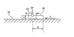
図3は、研磨パッド22をドレッシングしているときのドレッサー50に作用する力を説明するためのドレッサー50を示す模式図である。図3に示すように、ドレッサー50は、自在軸受52により傾動自在にドレッサーシャフト51に連結されている。この自在軸受52としては、球面軸受、板ばねなどが使用される。研磨パッド22のドレッシング中、ドレッサーシャフト51はドレッサー50に下向きの力DFを与える。回転する研磨テーブル12上の研磨パッド22の表面は、ドレッサー50に対して速度Vで移動する。この研磨パッド22の移動によりドレッサー50には水平方向の力Fxが作用する。この力Fxは、ドレッサー50が研磨パッド22の表面を削り取るときにドレッサー50の下面(以下、ドレッシング面という)と研磨パッド22の表面22aとの間に生じる摩擦力に相当する。
FIG. 3 is a schematic diagram showing the
図4は、研磨パッド22が速度Vで移動しているときに、ドレッサー50から研磨パッド22に作用する下向きの力の分布を示す模式図である。研磨パッド22はドレッサー50に対して相対的に速度Vで移動しているために、下向きの力DFは研磨パッド22の表面に対して不均一に作用する。結果として、ドレッサー50には、自在軸受52まわりにドレッサー50を反時計方向に回転させる反力が作用する。ドレッシング面上に分布する不均一な力が、図5に示すように研磨パッド22上の一点に集中すると仮定すると、自在軸受52まわりの反時計方向の力のモーメントM+は次の式で表される。
M+=Q*R*DF (1)
ここで、Rはドレッシング面の半径であり、Qはドレッシング面上に分布する不均一な力が研磨パッド22上の一点に集中すると仮定したときの力の作用点とドレッシング面の中心との距離を半径Rを用いて表すための変換係数である。変換係数Qは、1よりも小さい数値である。
FIG. 4 is a schematic diagram showing a downward force distribution acting on the
M + = Q * R * DF (1)
Here, R is the radius of the dressing surface, and Q is the distance between the point of application of the force and the center of the dressing surface when the uneven force distributed on the dressing surface is concentrated on one point on the
自在軸受52まわりの時計方向の力のモーメントM−は次の式で表される。
M−=Fx*h (2)
ここで、hはドレッサー50のドレッシング面と自在軸受52との距離である。
水平方向の力Fxは、ドレッサー50と研磨パッド22との摩擦力に相当する。したがって、水平方向の力Fxと下向きの力DFとの間には、基本的に相関関係がある。水平方向の力Fxと下向きの力DFとの関係は、係数Zを用いて次の式で表される。
Fx=Z*DF (3)
以下、本明細書では、係数Zを仕事係数と称する。
The moment M − of the clockwise force around the
M − = Fx * h (2)
Here, h is the distance between the dressing surface of the
The horizontal force Fx corresponds to the frictional force between the
Fx = Z * DF (3)
Hereinafter, in this specification, the coefficient Z is referred to as a work coefficient.
自在軸受52まわりの力のモーメントMは、
M=M+−M−
=Q*R*DF−h*Z*DF
=(Q*R−h*Z)*DF (4)
となる。
The moment M of the force around the
M = M + −M −
= Q * R * DF-h * Z * DF
= (Q * R-h * Z) * DF (4)
It becomes.
時計方向の力のモーメントM−が反時計方向の力のモーメントM+よりも大きいと、ドレッサー50は研磨パッド22に引っ掛かり(つまずき)、ドレッサー50の姿勢が不安定となる。したがって、自在軸受52まわりのドレッサー50の傾き運動の安定条件は、上記式(4)の括弧内の値が正の値であることである。具体的には、安定条件は次の通りである。
Q*R−h*Z>0 (5)
Qは予め決定された変換係数である。Rおよびhはドレッサー50の寸法から一意に決定される固定値である。したがって、仕事係数Zを研磨中に取得することにより、ドレッシングプロセスの安定性を監視することができる。
When the clockwise force moment M − is larger than the counterclockwise force moment M + , the
Q * R-h * Z> 0 (5)
Q is a predetermined conversion coefficient. R and h are fixed values uniquely determined from the dimensions of the
次に、仕事係数Zを取得する方法について説明する。水平方向の力Fxは、研磨テーブル12を回転させるテーブルモータ13のトルクと、ドレッサー50の研磨テーブル12の中心からの距離St(図2参照)から、次のように算出することができる。
Fx=(Tt−Tt0)/St (6)
ここで、Ttはドレッシング中のテーブルモータ13のトルクであり、Tt0はドレッサー50を研磨パッド22に接触させる前のテーブルモータ13の初期トルクである。
Next, a method for obtaining the work coefficient Z will be described. The horizontal force Fx can be calculated from the torque of the
Fx = (Tt−Tt 0 ) / St (6)
Here, Tt is the torque of the
テーブルモータ13のトルクは、テーブルモータ13に供給される電流に比例する。したがって、トルクTt,Tt0は、電流とトルク定数[Nm/A]とを掛けることにより求めることができる。トルク定数はテーブルモータ13に固有の定数であり、そのテーブルモータ13の仕様データから取得することができる。モータドライバ15からテーブルモータ13に供給される電流は、モータ電流測定器14により計測することができる。
The torque of the
ドレッシング中のドレッサー50は、研磨テーブル12の半径方向に揺動する。したがって、ドレッサー50と研磨テーブル12の中心との距離Stは、ドレッシング時間とともに周期的に変動する。距離Stは、ドレッサー50の旋回中心点Cと研磨テーブル12の中心Oとの相対位置、ドレッサー50と点Cとの距離L、ドレッサーアーム55の旋回角度θなどから計算することができる。
The
仕事係数Zは、上記式(3)および式(6)から次のように与えられる。
Z=Fx/DF
=(Tt−Tt0)/(DF*St) (7)
上記式(7)から分かるように、仕事係数Zは、ドレッサー50から研磨パッド22に作用する、研磨パッド22の表面22aと平行な力Fxと、ドレッサー50から研磨パッド22に作用する、研磨パッド22の表面22aに対して垂直に作用する力DFとの比である。
The work coefficient Z is given from the above equations (3) and (6) as follows.
Z = Fx / DF
= (Tt−Tt 0 ) / (DF * St) (7)
As can be seen from the above formula (7), the work coefficient Z is a force applied to the
パッド監視装置60は、ドレッシング中のテーブルモータ13のトルクTtと、テーブルモータ13の初期トルクTt0と、ドレッサー50に作用する下向きの力DFと、ドレッサー50と研磨テーブル12の中心との距離Stとから、仕事係数Zを上記式(7)を用いて算出する。下向きの力DFは、ドレッサーシャフト51に組み込まれたロードセル17により測定することができる。これに代えて、エアシリンダ53内の気体の圧力値にエアシリンダ53のピストンの受圧面積を掛けることにより下向きの力DFを算出してもよい。
The
ドレッシング面の半径Rをk*h(kは例えば2〜10)、変換係数Qを0.5と仮定すると、式(5)から、仕事係数Zが0.5kよりも大きいときにドレッサー50が不安定になることが分かる。パッド監視装置60は、研磨パッド22のドレッシング中に仕事係数Zを算出し、この仕事係数Zに基づいてドレッシングが正常に行われているか否かを監視する。
Assuming that the radius R of the dressing surface is k * h (k is, for example, 2 to 10) and the conversion coefficient Q is 0.5, from the equation (5), when the work coefficient Z is larger than 0.5k, It turns out that it becomes unstable. The
図6は、研磨パッド22のドレッシング中に取得された各種データを示す図である。図6の左側の縦軸は、ドレッサー50の研磨テーブル12の中心からの距離St[mm]、下向きの力DF[N]、水平方向の力Fx[N]、トルク差分Tt−Tt0[Nm]を表し、右側の縦軸は仕事係数Zを表し、横軸はドレッシング時間を表している。ドレッサー50の研磨テーブル12の半径方向の揺動は、ドレッサー50の研磨テーブル12の中心からの距離Stによって最もよく示されている。このドレッサー50の揺動に同期して、仕事係数Zが変化していることが図6から分かる。より具体的には、ドレッサー50が研磨パッド22(研磨テーブル12)のエッジ部から中心部に移動するに従って仕事係数Zおよび水平方向の力Fxが大きくなり、ドレッサー50が研磨パッド22の中心部に位置しているときに、仕事係数Zおよび水平方向の力Fxが最も大きくなる。これは、研磨パッド22のエッジ部から中心部に向かって移動しているドレッサー50のベクトルは、研磨テーブル12の回転方向と反対の方向の成分を持つためである。図6に示されるように、仕事係数Zは、ドレッシング中に変化しうる変数である。
FIG. 6 is a diagram showing various data acquired during dressing of the
図6に示すように、ドレッシング総時間を通じた水平方向の力Fxの平均は、概ね下向きの力DFと同じとなっている。ドレッサー50が研磨パッド22上を滑っている場合、すなわちドレッサー50が研磨パッド22を削り取っていない場合、仕事係数Zは0となる。図6に示す例では、仕事係数Zは概ね1を示し、その最大値は研磨テーブル12の中心での1.7である。このことは、ドレッサー50は研磨パッド22上を滑っていない、すなわち研磨パッド22を削り取っていることを示している。仕事係数Zが大きいドレッシングプロセスは、ドレッサー50が研磨パッド22を大きく削り取っているプロセスであり、この場合は、ドレッサー50の残存寿命が短くなると予想される。
As shown in FIG. 6, the average of the horizontal force Fx over the total dressing time is substantially the same as the downward force DF. When the
パッド監視装置60は、仕事係数Zが予め定められた範囲内にない場合には、ドレッシングが正しく行われていないと判断することができる。好ましくは、パッド監視装置60は、1回または複数回のドレッシング工程での仕事係数Zの平均が予め定められた範囲内にない場合には、ドレッシングが正しく行われていないと判断してもよい。
If the work coefficient Z is not within a predetermined range, the
水平方向の力Fxとドレッサー50の研磨パッド22の周方向の移動距離Sとの積は、ドレッサー50の仕事量W[J]を表す。移動距離Sは、研磨テーブル12(研磨パッド22)の中心からのドレッサー50の距離と、研磨テーブル12の回転速度とから算出することができる。
W=Fx*S[J] (8)
さらに、水平方向の力Fxとドレッサー50の研磨パッド22の周方向の単位時間当たりの移動距離dS/dtとの積は、ドレッサー50の仕事率P[J/s]を表す。
P=Fx*(dS/dt)[J/s] (9)
ドレッサー50の仕事量W[J]および仕事率P[J/s]は、どちらも、消耗品であるドレッサー50の残存寿命の予測に好適な指標となる。
The product of the horizontal force Fx and the circumferential movement distance S of the
W = Fx * S [J] (8)
Further, the product of the horizontal force Fx and the movement distance dS / dt of the
P = Fx * (dS / dt) [J / s] (9)
The work amount W [J] and the work rate P [J / s] of the
次に、消耗品であるドレッサー50の残存寿命を予測する方法について説明する。ドレッサー50の許容総仕事量をW0[J]、ドレッサー50の仕事量の累積値をW1[J]、単位時間当たりの仕事量(すなわち仕事率)をP[J/s]とすると、ドレッサー50の残存寿命Tendは次の式から求めることができる。
Tend[s]=(W0−W1)/P (10)
仕事率Pは、単位時間当たりの最新の仕事量である。この仕事率Pは、ある時間幅での移動平均であってもよい。
Next, a method for predicting the remaining life of the
Tend [s] = (W0−W1) / P (10)
The work rate P is the latest work amount per unit time. The power P may be a moving average over a certain time width.
式(3)から分かるように、仕事係数Zが0であるとき、下向きの力DFが研磨パッド22に作用しているにもかかわらず、水平方向の力Fxは0である。これは、ドレッサー50が研磨パッド22を削り取っていないことを意味する。ドレッサー50の砥粒が長時間の使用により摩耗してくると、ドレッサー50は研磨パッド22を削り取る能力を失っていく。したがって、仕事係数Zから、ドレッサー50の交換時期を決定することが可能である。
As can be seen from equation (3), when the work coefficient Z is 0, the horizontal force Fx is 0 even though the downward force DF is acting on the
次に、仕事係数Zを用いてドレッサー50の残存寿命を予測する方法について説明する。初期仕事係数をZ0、使用限界仕事係数をZend、単位時間当たりの仕事係数の変化量をdZ/dtとすると、ドレッサー50の残存寿命Tendは次の式から求めることができる。
Tend[s]=(Z0−Zend)/(dZ/dt) (11)
この場合も、仕事係数Zは、ある時間幅での移動平均であってもよく、単位時間当たりの仕事係数の変化量dZ/dtは、仕事係数Zの移動平均から算出してもよい。
Next, a method for predicting the remaining life of the
Tend [s] = (Z0−Zend) / (dZ / dt) (11)
Also in this case, the work coefficient Z may be a moving average over a certain time width, and the work coefficient change amount dZ / dt per unit time may be calculated from the moving average of the work coefficient Z.
仕事係数Zおよび単位時間当たりの仕事係数の変化量dZ/dtは、ドレッシング異常の検知に用いることができる。例えば、パッド監視装置60は、仕事係数Zおよび/または変化量dZ/dtが所定のしきい値に達したときは、ドレッシングプロセスの異常が発生したと判断するようにしてもよい。また、パッド監視装置60は、仕事係数Zまたはそのドレッシング工程を通じた平均が使用限界仕事係数Zendに達したときは、ドレッサー50の交換時期に達した、またはドレッサー50が故障したと判断するようにしてもよい。さらに、パッド監視装置60は、算出したドレッサー50の残存寿命が所定のしきい値に達したときには、ドレッサー50の交換を促す信号を発するようにしてもよい。
The work coefficient Z and the change amount dZ / dt of the work coefficient per unit time can be used for detecting a dressing abnormality. For example, the
このように、パッド監視装置60は、ドレッシング中に取得される仕事係数Zに基づいて、ドレッシングプロセスを監視し、さらにドレッサー50の残存寿命を監視することができる。さらに、仕事係数Zを用いたドレッシングプロセスの評価に基づいて、最適なドレッシングレシピを作成することが可能となる。
In this manner, the
パッド監視装置60は、ドレッシング時間全体を通じて仕事係数Zを算出し、ドレッシング中の各時点に対応する仕事係数Zを決定する。仕事係数Zが決定されたときのドレッサー50の研磨パッド22上の位置は、研磨装置の寸法およびドレッサー50の動作パラメータから特定することが可能である。したがって、決定された仕事係数Zと特定された研磨パッド22上のドレッサー50の位置から、研磨パッド22上の仕事係数Zの分布図を作成する事が可能である。
The
パッド監視装置60は、次のようにして研磨パッド22上の仕事係数Zの分布図を作成する。図7は、研磨パッド22とドレッサー50を模式的に示す平面図である。図7において、x−y座標系はベース3(図1参照)上に定義された固定座標系であり、X−Y座標系は研磨パッド22の研磨面22a上に定義された回転座標系である。図7に示すように、研磨テーブル12およびその上の研磨パッド22はx−y固定座標系の原点Oを中心として回転する。一方、ドレッサー50はx−y固定座標系上の所定の点Cを中心として所定の角度だけ旋回する。
The
研磨テーブル12と支軸58の相対位置は固定であるから、x−y固定座標系上の点Cの座標は必然的に決定される。点Cを中心とするドレッサー50の旋回角度θは、ドレッサーアーム55の旋回角度であり、この旋回角度θはドレッサー50ロータリエンコーダ32により計測される。研磨パッド22(研磨テーブル12)の回転角度αは、x−y固定座標系の座標軸とX−Y回転座標系の座標軸とがなす角度であり、この回転角度αはテーブルロータリエンコーダ31により計測される。
Since the relative position of the polishing table 12 and the
x−y固定座標系上のドレッサー50の中心の座標は、点Cの座標と、距離Lと、角度θとから決定することができる。さらに、X−Y回転座標系上のドレッサー50の中心の座標は、x−y固定座標系上のドレッサー50の中心の座標と、研磨パッド22の回転角度αとから決定することができる。固定座標系上の座標から回転座標系上の座標への変換は、公知の三角関数と四則演算を用いて行うことができる。
The coordinates of the center of the
パッド監視装置60は、回転角度αおよび旋回角度θから上述のようにしてX−Y回転座標系上のドレッサー50の中心の座標を算出する。X−Y回転座標系は、研磨面22a上に定義された二次元平面である。すなわち、X−Y回転座標系上のドレッサー50の座標は、研磨面22aに対するドレッサー50の相対位置を示す。このように、ドレッサー50の位置は、研磨面22aに定義された二次元平面上の位置として表される。
The
パッド監視装置60は、仕事係数Zを計算により取得するたびに、その仕事係数Zを取得したX−Y回転座標系上の座標を特定する。この座標は、取得した仕事係数Zに対応するドレッサー50の位置を示している。さらに、パッド監視装置60は、仕事係数Zを対応するX−Y回転座標系上の座標と関連付ける。各仕事係数および関連付けられた座標は、パッド監視装置60に記憶される。
Each time the
ドレッサー50のエッジ部が研磨パッド22の研磨面22aに引っ掛かると、研磨パッド22がドレッサー50により局所的に削られてしまい、研磨面22aの平坦度が失われてしまう。仕事係数Zが大きくなると、ドレッサー50は研磨パッド22に引っ掛かりやすくなることが式(5)から分かる。そこで、パッド監視装置60は、算出された仕事係数Zに基づいて、研磨面22aが平坦であるか否か、すなわち研磨パッド22のドレッシングが正しく行われているか否かを監視する。すなわち、パッド監視装置60は、所定のしきい値を超えた仕事係数Zを異常点として、研磨パッド22上に定義されたX−Y回転座標系上にプロット(表示)し、図8に示すような仕事係数分布を生成する。
When the edge portion of the
パッド監視装置60は、二次元平面上に表示された異常点の密度を計算する機能をさらに備えている。パッド監視装置60は、二次元平面内の複数の領域内において異常点密度を計算し、各領域において異常点密度が所定の値を超えたか否かを決定する。この領域は、研磨面22a上のX−Y回転座標系上に予め定義された格子状の領域である。
The
図9は、X−Y回転座標系上に定義された複数の領域を示す図である。異常点の密度は、各領域90での異常点の数を領域90の面積で割ることにより求めることができる。図9の符号90’は、異常点の密度が所定の値に達した領域を示している。図9に示すように、異常点の密度が所定の値に達した領域に色を付けることが好ましい。パッド監視装置60は、少なくとも1つの領域90において異常点の密度が所定の値を超えたときには、研磨パッド22のドレッシングが正常に行われていないことを示す信号を出力する。
FIG. 9 is a diagram showing a plurality of regions defined on the XY rotating coordinate system. The density of abnormal points can be obtained by dividing the number of abnormal points in each
このように、仕事係数Zの異常点を二次元平面上に表すことができるので、研磨面22aの平坦度が失われる前に、研磨パッド22を新たな研磨パッドに交換することができる。したがって、製品の歩留まりの低下を未然に防ぐことができる。さらに、研磨パッド22のドレッシングが正常に行われているか否かを、研磨パッド22のドレッシング中に知ることができる。異常点の発生を視覚的に認識しやすくするために、異常点の密度を色の濃淡で表すことが好ましい。仕事係数Zに代えて、単位時間あたりの仕事係数Zの変化量dZ/dtの異常点を二次元平面上に表ことも可能である。
Thus, since the abnormal point of the work coefficient Z can be represented on a two-dimensional plane, the
これまで本発明の実施形態について説明したが、本発明は上述の実施形態に限定されず、その技術的思想の範囲内において種々異なる形態にて実施されてよいことは言うまでもない。 Although the embodiments of the present invention have been described so far, it is needless to say that the present invention is not limited to the above-described embodiments and may be implemented in various forms within the scope of the technical idea.
1 研磨ユニット
2 ドレッシングユニット
3 ベース
5 研磨液供給ノズル
12 研磨テーブル
13 テーブルモータ
14 モータ電流測定器
15 モータドライバ
16 圧力センサ
17 ロードセル
20 トップリング
22 研磨パッド
22a 研磨面
31 テーブルロータリエンコーダ
32 ドレッサーロータリエンコーダ
50 ドレッサー
52 自在軸受
55 ドレッサーアーム
60 パッド監視装置
DESCRIPTION OF
Claims (16)
ドレッサーを前記研磨パッドの半径方向に揺動させながら、回転する前記研磨パッドに前記ドレッサーを押し付けて前記研磨パッドをドレッシングし、
前記研磨パッドのドレッシング中に、前記ドレッサーと前記研磨パッドとの間に働く摩擦力と前記押し付け力との比を示す仕事係数を算出し、
前記仕事係数に基づいて、前記ドレッサーの残存寿命を決定し、
前記ドレッサーの残存寿命をTend、初期仕事係数をZ0、使用限界仕事係数をZend、単位時間当たりの仕事係数の変化量をdZ/dtとすると、前記ドレッサーの残存寿命は、
Tend=(Z0−Zend)/(dZ/dt)
で表されることを特徴とする研磨パッドのドレッシングの監視方法。 Rotate the polishing table that supports the polishing pad,
Dressing the polishing pad by pressing the dresser against the rotating polishing pad while swinging the dresser in the radial direction of the polishing pad;
During the dressing of the polishing pad, calculate a work coefficient indicating the ratio of the frictional force acting between the dresser and the polishing pad and the pressing force,
Based on the work factor, determine the remaining life of the dresser;
When the remaining life of the dresser is Tend, the initial work coefficient is Z0, the working limit work coefficient is Zend, and the change amount of the work coefficient per unit time is dZ / dt, the remaining life of the dresser is
Tend = (Z0−Zend) / (dZ / dt)
A method for monitoring dressing of a polishing pad, characterized by:
Z=(Tt−Tt0)/(DF*St)
で表されることを特徴とする請求項2に記載の方法。 The work coefficient is Z, the torque of the table motor during dressing is Tt, the initial torque of the table motor before the dresser contacts the polishing pad, Tt0, the pressing force is DF, the dresser and the polishing table When the distance from the center is St, the work coefficient is
Z = (Tt−Tt 0 ) / (DF * St)
The method of claim 2, wherein:
前記単位時間当たりの仕事係数の変化量は、前記仕事係数の移動平均から算出されることを特徴とする請求項1に記載の方法。 The method according to claim 1, wherein the change amount of the work coefficient per unit time is calculated from a moving average of the work coefficient.
ドレッサーを前記研磨パッドの半径方向に揺動させながら、回転する前記研磨パッドに前記ドレッサーを押し付けて前記研磨パッドをドレッシングし、
前記研磨パッドのドレッシング中に、前記ドレッサーと前記研磨パッドとの間に働く摩擦力と前記押し付け力との比を示す仕事係数を算出し、
単位時間当たりの前記仕事係数の変化量と所定のしきい値との比較により、前記研磨パッドのドレッシングの異常を検知することを特徴とする研磨パッドのドレッシングの監視方法。 Rotate the polishing table that supports the polishing pad,
Dressing the polishing pad by pressing the dresser against the rotating polishing pad while swinging the dresser in the radial direction of the polishing pad;
During the dressing of the polishing pad, calculate a work coefficient indicating the ratio of the frictional force acting between the dresser and the polishing pad and the pressing force,
A polishing pad dressing monitoring method, comprising: detecting a polishing pad dressing abnormality by comparing a change amount of the work coefficient per unit time with a predetermined threshold value.
Z=(Tt−Tt Z = (Tt−Tt 00 )/(DF*St)) / (DF * St)
で表されることを特徴とする請求項7に記載の方法。 The method of claim 7, wherein:
前記研磨テーブルを回転させるテーブルモータと、
研磨パッドをドレッシングするドレッサーと、
前記ドレッサーを前記研磨パッドの半径方向に揺動させる旋回モータと、
回転する前記研磨パッドに前記ドレッサーを押し付ける押圧機構と、
前記研磨パッドのドレッシングを監視するパッド監視装置とを備え、
前記パッド監視装置は、
前記研磨パッドのドレッシング中に、前記ドレッサーと前記研磨パッドとの間に働く摩擦力と前記押し付け力との比を示す仕事係数を算出し、
前記仕事係数に基づいて、前記ドレッサーの残存寿命を決定し、
前記ドレッサーの残存寿命をTend、初期仕事係数をZ0、使用限界仕事係数をZend、単位時間当たりの仕事係数の変化量をdZ/dtとすると、前記ドレッサーの残存寿命は、
Tend=(Z0−Zend)/(dZ/dt)
で表されることを特徴とする研磨装置。 A polishing table that supports the polishing pad;
A table motor for rotating the polishing table;
A dresser for dressing the polishing pad;
A turning motor for swinging the dresser in the radial direction of the polishing pad;
A pressing mechanism that presses the dresser against the rotating polishing pad;
A pad monitoring device for monitoring the dressing of the polishing pad;
The pad monitoring device
During the dressing of the polishing pad, calculate a work coefficient indicating the ratio of the frictional force acting between the dresser and the polishing pad and the pressing force,
Based on the work factor, determine the remaining life of the dresser;
When the remaining life of the dresser is Tend, the initial work coefficient is Z0, the working limit work coefficient is Zend, and the change amount of the work coefficient per unit time is dZ / dt, the remaining life of the dresser is
Tend = (Z0−Zend) / (dZ / dt)
In polishing apparatus characterized by being represented.
Z=(Tt−Tt0)/(DF*St)
で表されることを特徴とする請求項10に記載の研磨装置。 The work coefficient is Z, the torque of the table motor during dressing is Tt, the initial torque of the table motor before the dresser contacts the polishing pad, Tt0, the pressing force is DF, the dresser and the polishing table When the distance from the center is St, the work coefficient is
Z = (Tt−Tt0) / (DF * St)
The polishing apparatus according to claim 10, wherein
前記単位時間当たりの仕事係数の変化量は、前記仕事係数の移動平均から算出されることを特徴とする請求項9に記載の研磨装置。 The polishing apparatus according to claim 9, wherein the change amount of the work coefficient per unit time is calculated from a moving average of the work coefficients.
前記研磨テーブルを回転させるテーブルモータと、
研磨パッドをドレッシングするドレッサーと、
前記ドレッサーを前記研磨パッドの半径方向に揺動させる旋回モータと、
回転する前記研磨パッドに前記ドレッサーを押し付ける押圧機構と、
前記研磨パッドのドレッシングを監視するパッド監視装置とを備え、
前記パッド監視装置は、
前記研磨パッドのドレッシング中に、前記ドレッサーと前記研磨パッドとの間に働く摩擦力と前記押し付け力との比を示す仕事係数を算出し、
単位時間当たりの前記仕事係数の変化量と所定のしきい値との比較により、前記研磨パッドのドレッシングの異常を検知することを特徴とする研磨装置。 A polishing table that supports the polishing pad;
A table motor for rotating the polishing table;
A dresser for dressing the polishing pad;
A turning motor for swinging the dresser in the radial direction of the polishing pad;
A pressing mechanism that presses the dresser against the rotating polishing pad;
A pad monitoring device for monitoring the dressing of the polishing pad;
The pad monitoring device
During the dressing of the polishing pad, calculate a work coefficient indicating the ratio of the frictional force acting between the dresser and the polishing pad and the pressing force,
Single-position by comparing the variation of the work coefficient per time and with a predetermined threshold, the polishing pad dressing abnormalities Migaku Ken apparatus you and detecting the.
Z=(Tt−Tt0)/(DF*St) Z = (Tt−Tt0) / (DF * St)
で表されることを特徴とする請求項15に記載の研磨装置。 The polishing apparatus according to claim 15, represented by:
Priority Applications (11)
| Application Number | Priority Date | Filing Date | Title |
|---|---|---|---|
| JP2012187383A JP5927083B2 (en) | 2012-08-28 | 2012-08-28 | Dressing process monitoring method and polishing apparatus |
| KR1020130100392A KR102054843B1 (en) | 2012-08-28 | 2013-08-23 | Monitoring method for dressing process and polishing apparatus |
| US14/011,668 US9808908B2 (en) | 2012-08-28 | 2013-08-27 | Method of monitoring a dressing process and polishing apparatus |
| CN201310384344.2A CN103659605B (en) | 2012-08-28 | 2013-08-27 | The monitoring method and lapping device of finishing |
| CN201710599619.2A CN107263320B (en) | 2012-08-28 | 2013-08-27 | The monitoring method and grinding device of finishing |
| TW106145303A TWI658898B (en) | 2012-08-28 | 2013-08-28 | Monitoring method and grinding device for trimming process |
| TW102130760A TWI655997B (en) | 2012-08-28 | 2013-08-28 | Monitoring method and grinding device for trimming process |
| JP2016087090A JP6113326B2 (en) | 2012-08-28 | 2016-04-25 | Dressing process monitoring method and polishing apparatus |
| US15/721,211 US10675731B2 (en) | 2012-08-28 | 2017-09-29 | Method of monitoring a dressing process and polishing apparatus |
| KR1020190159028A KR102181464B1 (en) | 2012-08-28 | 2019-12-03 | Monitoring method for dressing process and polishing apparatus |
| US16/861,729 US11325224B2 (en) | 2012-08-28 | 2020-04-29 | Method of monitoring a dressing process and polishing apparatus |
Applications Claiming Priority (1)
| Application Number | Priority Date | Filing Date | Title |
|---|---|---|---|
| JP2012187383A JP5927083B2 (en) | 2012-08-28 | 2012-08-28 | Dressing process monitoring method and polishing apparatus |
Related Child Applications (1)
| Application Number | Title | Priority Date | Filing Date |
|---|---|---|---|
| JP2016087090A Division JP6113326B2 (en) | 2012-08-28 | 2016-04-25 | Dressing process monitoring method and polishing apparatus |
Publications (2)
| Publication Number | Publication Date |
|---|---|
| JP2014042968A JP2014042968A (en) | 2014-03-13 |
| JP5927083B2 true JP5927083B2 (en) | 2016-05-25 |
Family
ID=50188183
Family Applications (2)
| Application Number | Title | Priority Date | Filing Date |
|---|---|---|---|
| JP2012187383A Active JP5927083B2 (en) | 2012-08-28 | 2012-08-28 | Dressing process monitoring method and polishing apparatus |
| JP2016087090A Active JP6113326B2 (en) | 2012-08-28 | 2016-04-25 | Dressing process monitoring method and polishing apparatus |
Family Applications After (1)
| Application Number | Title | Priority Date | Filing Date |
|---|---|---|---|
| JP2016087090A Active JP6113326B2 (en) | 2012-08-28 | 2016-04-25 | Dressing process monitoring method and polishing apparatus |
Country Status (5)
| Country | Link |
|---|---|
| US (3) | US9808908B2 (en) |
| JP (2) | JP5927083B2 (en) |
| KR (2) | KR102054843B1 (en) |
| CN (2) | CN103659605B (en) |
| TW (2) | TWI655997B (en) |
Families Citing this family (32)
| Publication number | Priority date | Publication date | Assignee | Title |
|---|---|---|---|---|
| JP2008536452A (en) | 2005-04-13 | 2008-09-04 | トムソン ライセンシング | Method and apparatus for video encoding |
| JP6307428B2 (en) | 2014-12-26 | 2018-04-04 | 株式会社荏原製作所 | Polishing apparatus and control method thereof |
| JP6592355B2 (en) * | 2015-01-30 | 2019-10-16 | 株式会社荏原製作所 | Connecting mechanism and substrate polishing apparatus |
| JP6444785B2 (en) * | 2015-03-19 | 2018-12-26 | 株式会社荏原製作所 | Polishing apparatus, control method therefor, and dressing condition output method |
| JP6649073B2 (en) * | 2015-12-16 | 2020-02-19 | 株式会社荏原製作所 | Substrate processing apparatus and quality assurance method thereof |
| JP6715153B2 (en) * | 2016-09-30 | 2020-07-01 | 株式会社荏原製作所 | Substrate polishing equipment |
| CN106597841B (en) * | 2016-12-14 | 2019-09-24 | 北京半导体专用设备研究所(中国电子科技集团公司第四十五研究所) | The spotting scaming algorithm of trimmer motor in chemical-mechanical planarization |
| CN106392884B (en) * | 2016-12-14 | 2019-10-18 | 北京中电科电子装备有限公司 | A kind of the finishing control system and method for grinding wheel |
| US10675732B2 (en) | 2017-04-18 | 2020-06-09 | Taiwan Semiconductor Manufacturing Company, Ltd. | Apparatus and method for CMP pad conditioning |
| CN107662159B (en) * | 2017-09-15 | 2019-04-02 | 清华大学 | Modify control method, device, trimmer and the polissoir of polishing pad |
| CN107900909A (en) * | 2017-11-15 | 2018-04-13 | 上海华力微电子有限公司 | A kind of method and grinding pad conditioner discs for extending grinding pad conditioner discs service life |
| US11292101B2 (en) * | 2017-11-22 | 2022-04-05 | Taiwan Semiconductor Manufacturing Co., Ltd. | Chemical mechanical polishing apparatus and method |
| JP7098311B2 (en) * | 2017-12-05 | 2022-07-11 | 株式会社荏原製作所 | Polishing equipment and polishing method |
| CN108145594A (en) * | 2017-12-21 | 2018-06-12 | 上海华力微电子有限公司 | The monitoring method and monitoring device of useful time of grinding pad |
| KR102546838B1 (en) * | 2018-03-26 | 2023-06-23 | 주식회사 케이씨텍 | Substrate treating appratus |
| KR102561647B1 (en) | 2018-05-28 | 2023-07-31 | 삼성전자주식회사 | Conditioner and chemical mechanical polishing apparatus including the same |
| JP7287761B2 (en) * | 2018-07-31 | 2023-06-06 | 株式会社荏原製作所 | Bearing radius determination method for spherical bearings |
| CN109015335A (en) * | 2018-09-27 | 2018-12-18 | 德淮半导体有限公司 | Chemical mechanical polishing device and its working method |
| TWI819138B (en) * | 2018-12-21 | 2023-10-21 | 日商荏原製作所股份有限公司 | Grinding device and dressing method of grinding components |
| CN109664179B (en) * | 2019-01-02 | 2021-05-04 | 中国科学院上海光学精密机械研究所 | Annular polishing machine |
| CN111482902A (en) * | 2020-04-14 | 2020-08-04 | 长春长光圆辰微电子技术有限公司 | Method for pressure adjustment of dresser in chemical mechanical polishing |
| CN111515863A (en) * | 2020-04-30 | 2020-08-11 | 武汉新芯集成电路制造有限公司 | Polishing method and polishing pad dressing system |
| CN111571444A (en) * | 2020-05-15 | 2020-08-25 | 中国科学院微电子研究所 | Polishing pad dressing device |
| JP2022032201A (en) * | 2020-08-11 | 2022-02-25 | 株式会社荏原製作所 | Substrate processor and dressing control method for polishing member |
| JP7421460B2 (en) | 2020-09-29 | 2024-01-24 | 株式会社荏原製作所 | Polishing equipment and how to determine when to replace polishing pads |
| TWI752734B (en) * | 2020-11-19 | 2022-01-11 | 台達電子工業股份有限公司 | Rotary machine device and linear machine device |
| CN114520577B (en) | 2020-11-19 | 2023-11-03 | 台达电子工业股份有限公司 | Rotary mechanical device and linear mechanical device |
| TWI820399B (en) * | 2021-02-26 | 2023-11-01 | 國立臺灣科技大學 | Wafer processing method and wafer processing system |
| CN113319739B (en) * | 2021-05-06 | 2022-09-30 | 西安理工大学 | Trimming mechanism for realizing self-trimming abrasive disk of single-plane grinding machine |
| TWI766697B (en) * | 2021-05-24 | 2022-06-01 | 聯毅科技股份有限公司 | Device and method for monitoring |
| CN113334238A (en) * | 2021-06-22 | 2021-09-03 | 上海华虹宏力半导体制造有限公司 | Method and apparatus for controlling chemical mechanical polishing |
| CN113561060B (en) * | 2021-07-28 | 2022-10-21 | 北京烁科精微电子装备有限公司 | Control method, device and system of diamond collator |
Family Cites Families (24)
| Publication number | Priority date | Publication date | Assignee | Title |
|---|---|---|---|---|
| JPH10315124A (en) * | 1997-05-16 | 1998-12-02 | Hitachi Ltd | Polishing method and polishing device |
| US6191038B1 (en) * | 1997-09-02 | 2001-02-20 | Matsushita Electronics Corporation | Apparatus and method for chemical/mechanical polishing |
| JP2977543B2 (en) * | 1997-09-02 | 1999-11-15 | 松下電子工業株式会社 | Chemical mechanical polishing apparatus and chemical mechanical polishing method |
| JP4030247B2 (en) * | 1999-05-17 | 2008-01-09 | 株式会社荏原製作所 | Dressing device and polishing device |
| DE60121292T2 (en) * | 2001-04-02 | 2007-07-05 | Infineon Technologies Ag | Method of conditioning the surface of a polishing pad |
| JP2005131732A (en) | 2003-10-30 | 2005-05-26 | Ebara Corp | Grinding device |
| US6986705B2 (en) * | 2004-04-05 | 2006-01-17 | Rimpad Tech Ltd. | Polishing pad and method of making same |
| JP2006004992A (en) * | 2004-06-15 | 2006-01-05 | Seiko Epson Corp | Polishing device managing system, managing device, control program thereof and control method thereof |
| US6953382B1 (en) * | 2004-06-24 | 2005-10-11 | Novellus Systems, Inc. | Methods and apparatuses for conditioning polishing surfaces utilized during CMP processing |
| JP4817687B2 (en) | 2005-03-18 | 2011-11-16 | 株式会社荏原製作所 | Polishing equipment |
| US8412370B2 (en) | 2005-04-01 | 2013-04-02 | Nikon Corporation | Polishing apparatus with dressing position setting means |
| EP1952945B1 (en) | 2007-01-30 | 2010-09-15 | Ebara Corporation | Polishing apparatus |
| JP5219395B2 (en) * | 2007-03-29 | 2013-06-26 | 株式会社東京精密 | Wafer polishing monitoring method and apparatus |
| JP2009033038A (en) * | 2007-07-30 | 2009-02-12 | Elpida Memory Inc | Cmp device, and wafer polishing method by cmp |
| US7828625B2 (en) * | 2007-10-30 | 2010-11-09 | United Microelectronics Corp. | Method of supplying polishing liquid |
| JP4658182B2 (en) | 2007-11-28 | 2011-03-23 | 株式会社荏原製作所 | Polishing pad profile measurement method |
| US8337279B2 (en) * | 2008-06-23 | 2012-12-25 | Applied Materials, Inc. | Closed-loop control for effective pad conditioning |
| US8096852B2 (en) * | 2008-08-07 | 2012-01-17 | Applied Materials, Inc. | In-situ performance prediction of pad conditioning disk by closed loop torque monitoring |
| JP5415735B2 (en) * | 2008-09-26 | 2014-02-12 | 株式会社荏原製作所 | Dressing method, dressing condition determining method, dressing condition determining program, and polishing apparatus |
| CN201333661Y (en) * | 2009-01-18 | 2009-10-28 | 湖南宇晶机器实业有限公司 | Device for controlling soft pressure of upper grinding plate in grinding machine |
| JP5306065B2 (en) | 2009-06-04 | 2013-10-02 | 株式会社荏原製作所 | Dressing apparatus and dressing method |
| KR20130059312A (en) * | 2010-04-30 | 2013-06-05 | 어플라이드 머티어리얼스, 인코포레이티드 | Pad conditioning sweep torque modeling to achieve constant removal rate |
| JP5511600B2 (en) * | 2010-09-09 | 2014-06-04 | 株式会社荏原製作所 | Polishing equipment |
| JP5896625B2 (en) | 2011-06-02 | 2016-03-30 | 株式会社荏原製作所 | Method and apparatus for monitoring the polishing surface of a polishing pad used in a polishing apparatus |
-
2012
- 2012-08-28 JP JP2012187383A patent/JP5927083B2/en active Active
-
2013
- 2013-08-23 KR KR1020130100392A patent/KR102054843B1/en active Application Filing
- 2013-08-27 CN CN201310384344.2A patent/CN103659605B/en active Active
- 2013-08-27 CN CN201710599619.2A patent/CN107263320B/en active Active
- 2013-08-27 US US14/011,668 patent/US9808908B2/en active Active
- 2013-08-28 TW TW102130760A patent/TWI655997B/en active
- 2013-08-28 TW TW106145303A patent/TWI658898B/en active
-
2016
- 2016-04-25 JP JP2016087090A patent/JP6113326B2/en active Active
-
2017
- 2017-09-29 US US15/721,211 patent/US10675731B2/en active Active
-
2019
- 2019-12-03 KR KR1020190159028A patent/KR102181464B1/en active IP Right Grant
-
2020
- 2020-04-29 US US16/861,729 patent/US11325224B2/en active Active
Also Published As
| Publication number | Publication date |
|---|---|
| US11325224B2 (en) | 2022-05-10 |
| TW201811500A (en) | 2018-04-01 |
| TWI655997B (en) | 2019-04-11 |
| US20180021920A1 (en) | 2018-01-25 |
| US20140065931A1 (en) | 2014-03-06 |
| US20200254585A1 (en) | 2020-08-13 |
| CN103659605B (en) | 2017-08-11 |
| JP2016129931A (en) | 2016-07-21 |
| CN107263320A (en) | 2017-10-20 |
| CN107263320B (en) | 2018-09-28 |
| KR102181464B1 (en) | 2020-11-23 |
| KR20140030045A (en) | 2014-03-11 |
| KR102054843B1 (en) | 2019-12-12 |
| TWI658898B (en) | 2019-05-11 |
| US9808908B2 (en) | 2017-11-07 |
| CN103659605A (en) | 2014-03-26 |
| KR20190138765A (en) | 2019-12-16 |
| TW201412457A (en) | 2014-04-01 |
| JP2014042968A (en) | 2014-03-13 |
| JP6113326B2 (en) | 2017-04-12 |
| US10675731B2 (en) | 2020-06-09 |
Similar Documents
| Publication | Publication Date | Title |
|---|---|---|
| JP6113326B2 (en) | Dressing process monitoring method and polishing apparatus | |
| KR101821886B1 (en) | Method and apparatus for monitoring a polishing surface of a polishing pad used in polishing apparatus | |
| US20170252889A1 (en) | Polishing apparatus | |
| JP6000960B2 (en) | Apparatus and method for compensating variation in chemical mechanical polishing consumables | |
| US20130122783A1 (en) | Pad conditioning force modeling to achieve constant removal rate | |
| JP2005081461A (en) | Polishing method and device of wafer or the like |
Legal Events
| Date | Code | Title | Description |
|---|---|---|---|
| A621 | Written request for application examination |
Free format text: JAPANESE INTERMEDIATE CODE: A621 Effective date: 20150311 |
|
| A131 | Notification of reasons for refusal |
Free format text: JAPANESE INTERMEDIATE CODE: A131 Effective date: 20151222 |
|
| A977 | Report on retrieval |
Free format text: JAPANESE INTERMEDIATE CODE: A971007 Effective date: 20151225 |
|
| A521 | Request for written amendment filed |
Free format text: JAPANESE INTERMEDIATE CODE: A523 Effective date: 20160215 |
|
| TRDD | Decision of grant or rejection written | ||
| A01 | Written decision to grant a patent or to grant a registration (utility model) |
Free format text: JAPANESE INTERMEDIATE CODE: A01 Effective date: 20160412 |
|
| A61 | First payment of annual fees (during grant procedure) |
Free format text: JAPANESE INTERMEDIATE CODE: A61 Effective date: 20160425 |
|
| R150 | Certificate of patent or registration of utility model |
Ref document number: 5927083 Country of ref document: JP Free format text: JAPANESE INTERMEDIATE CODE: R150 |
|
| R250 | Receipt of annual fees |
Free format text: JAPANESE INTERMEDIATE CODE: R250 |
|
| R250 | Receipt of annual fees |
Free format text: JAPANESE INTERMEDIATE CODE: R250 |
|
| R250 | Receipt of annual fees |
Free format text: JAPANESE INTERMEDIATE CODE: R250 |
|
| R250 | Receipt of annual fees |
Free format text: JAPANESE INTERMEDIATE CODE: R250 |
|
| R250 | Receipt of annual fees |
Free format text: JAPANESE INTERMEDIATE CODE: R250 |
|
| R250 | Receipt of annual fees |
Free format text: JAPANESE INTERMEDIATE CODE: R250 |