JP5924147B2 - Display device, image processing device, and display method - Google Patents
Display device, image processing device, and display method Download PDFInfo
- Publication number
- JP5924147B2 JP5924147B2 JP2012134373A JP2012134373A JP5924147B2 JP 5924147 B2 JP5924147 B2 JP 5924147B2 JP 2012134373 A JP2012134373 A JP 2012134373A JP 2012134373 A JP2012134373 A JP 2012134373A JP 5924147 B2 JP5924147 B2 JP 5924147B2
- Authority
- JP
- Japan
- Prior art keywords
- pixel
- sub
- luminance information
- luminance
- gain
- Prior art date
- Legal status (The legal status is an assumption and is not a legal conclusion. Google has not performed a legal analysis and makes no representation as to the accuracy of the status listed.)
- Expired - Fee Related
Links
Images


Classifications
-
- G—PHYSICS
- G09—EDUCATION; CRYPTOGRAPHY; DISPLAY; ADVERTISING; SEALS
- G09G—ARRANGEMENTS OR CIRCUITS FOR CONTROL OF INDICATING DEVICES USING STATIC MEANS TO PRESENT VARIABLE INFORMATION
- G09G3/00—Control arrangements or circuits, of interest only in connection with visual indicators other than cathode-ray tubes
- G09G3/20—Control arrangements or circuits, of interest only in connection with visual indicators other than cathode-ray tubes for presentation of an assembly of a number of characters, e.g. a page, by composing the assembly by combination of individual elements arranged in a matrix no fixed position being assigned to or needed to be assigned to the individual characters or partial characters
- G09G3/22—Control arrangements or circuits, of interest only in connection with visual indicators other than cathode-ray tubes for presentation of an assembly of a number of characters, e.g. a page, by composing the assembly by combination of individual elements arranged in a matrix no fixed position being assigned to or needed to be assigned to the individual characters or partial characters using controlled light sources
- G09G3/30—Control arrangements or circuits, of interest only in connection with visual indicators other than cathode-ray tubes for presentation of an assembly of a number of characters, e.g. a page, by composing the assembly by combination of individual elements arranged in a matrix no fixed position being assigned to or needed to be assigned to the individual characters or partial characters using controlled light sources using electroluminescent panels
- G09G3/32—Control arrangements or circuits, of interest only in connection with visual indicators other than cathode-ray tubes for presentation of an assembly of a number of characters, e.g. a page, by composing the assembly by combination of individual elements arranged in a matrix no fixed position being assigned to or needed to be assigned to the individual characters or partial characters using controlled light sources using electroluminescent panels semiconductive, e.g. using light-emitting diodes [LED]
- G09G3/3208—Control arrangements or circuits, of interest only in connection with visual indicators other than cathode-ray tubes for presentation of an assembly of a number of characters, e.g. a page, by composing the assembly by combination of individual elements arranged in a matrix no fixed position being assigned to or needed to be assigned to the individual characters or partial characters using controlled light sources using electroluminescent panels semiconductive, e.g. using light-emitting diodes [LED] organic, e.g. using organic light-emitting diodes [OLED]
-
- G—PHYSICS
- G09—EDUCATION; CRYPTOGRAPHY; DISPLAY; ADVERTISING; SEALS
- G09G—ARRANGEMENTS OR CIRCUITS FOR CONTROL OF INDICATING DEVICES USING STATIC MEANS TO PRESENT VARIABLE INFORMATION
- G09G2300/00—Aspects of the constitution of display devices
- G09G2300/04—Structural and physical details of display devices
- G09G2300/0439—Pixel structures
- G09G2300/0452—Details of colour pixel setup, e.g. pixel composed of a red, a blue and two green components
-
- G—PHYSICS
- G09—EDUCATION; CRYPTOGRAPHY; DISPLAY; ADVERTISING; SEALS
- G09G—ARRANGEMENTS OR CIRCUITS FOR CONTROL OF INDICATING DEVICES USING STATIC MEANS TO PRESENT VARIABLE INFORMATION
- G09G2320/00—Control of display operating conditions
- G09G2320/06—Adjustment of display parameters
- G09G2320/0626—Adjustment of display parameters for control of overall brightness
- G09G2320/0646—Modulation of illumination source brightness and image signal correlated to each other
-
- G—PHYSICS
- G09—EDUCATION; CRYPTOGRAPHY; DISPLAY; ADVERTISING; SEALS
- G09G—ARRANGEMENTS OR CIRCUITS FOR CONTROL OF INDICATING DEVICES USING STATIC MEANS TO PRESENT VARIABLE INFORMATION
- G09G2320/00—Control of display operating conditions
- G09G2320/06—Adjustment of display parameters
- G09G2320/066—Adjustment of display parameters for control of contrast
-
- G—PHYSICS
- G09—EDUCATION; CRYPTOGRAPHY; DISPLAY; ADVERTISING; SEALS
- G09G—ARRANGEMENTS OR CIRCUITS FOR CONTROL OF INDICATING DEVICES USING STATIC MEANS TO PRESENT VARIABLE INFORMATION
- G09G2320/00—Control of display operating conditions
- G09G2320/06—Adjustment of display parameters
- G09G2320/0666—Adjustment of display parameters for control of colour parameters, e.g. colour temperature
-
- G—PHYSICS
- G09—EDUCATION; CRYPTOGRAPHY; DISPLAY; ADVERTISING; SEALS
- G09G—ARRANGEMENTS OR CIRCUITS FOR CONTROL OF INDICATING DEVICES USING STATIC MEANS TO PRESENT VARIABLE INFORMATION
- G09G2340/00—Aspects of display data processing
- G09G2340/06—Colour space transformation
-
- G—PHYSICS
- G09—EDUCATION; CRYPTOGRAPHY; DISPLAY; ADVERTISING; SEALS
- G09G—ARRANGEMENTS OR CIRCUITS FOR CONTROL OF INDICATING DEVICES USING STATIC MEANS TO PRESENT VARIABLE INFORMATION
- G09G2360/00—Aspects of the architecture of display systems
- G09G2360/14—Detecting light within display terminals, e.g. using a single or a plurality of photosensors
- G09G2360/145—Detecting light within display terminals, e.g. using a single or a plurality of photosensors the light originating from the display screen
- G09G2360/147—Detecting light within display terminals, e.g. using a single or a plurality of photosensors the light originating from the display screen the originated light output being determined for each pixel
-
- G—PHYSICS
- G09—EDUCATION; CRYPTOGRAPHY; DISPLAY; ADVERTISING; SEALS
- G09G—ARRANGEMENTS OR CIRCUITS FOR CONTROL OF INDICATING DEVICES USING STATIC MEANS TO PRESENT VARIABLE INFORMATION
- G09G2360/00—Aspects of the architecture of display systems
- G09G2360/16—Calculation or use of calculated indices related to luminance levels in display data
-
- G—PHYSICS
- G09—EDUCATION; CRYPTOGRAPHY; DISPLAY; ADVERTISING; SEALS
- G09G—ARRANGEMENTS OR CIRCUITS FOR CONTROL OF INDICATING DEVICES USING STATIC MEANS TO PRESENT VARIABLE INFORMATION
- G09G3/00—Control arrangements or circuits, of interest only in connection with visual indicators other than cathode-ray tubes
- G09G3/20—Control arrangements or circuits, of interest only in connection with visual indicators other than cathode-ray tubes for presentation of an assembly of a number of characters, e.g. a page, by composing the assembly by combination of individual elements arranged in a matrix no fixed position being assigned to or needed to be assigned to the individual characters or partial characters
- G09G3/2003—Display of colours
Description
本開示は、画像を表示する表示装置、そのような表示装置に用いられる画像処理装置、および表示方法に関する。 The present disclosure relates to a display device that displays an image, an image processing device used in such a display device, and a display method.
近年、CRT(Cathode Ray Tube)表示装置から液晶表示装置や有機EL(Electro- Luminescence)表示装置への置き換えが進んでいる。これらの表示装置は、CRT表示装置に比べ、消費電力を低くすることができるとともに、薄型の表示装置を構成できるため、表示装置の主流になりつつある。 In recent years, replacement of CRT (Cathode Ray Tube) display devices with liquid crystal display devices and organic EL (Electro-Luminescence) display devices has progressed. These display devices are becoming mainstream of display devices because they can reduce power consumption as compared to CRT display devices and can form thin display devices.
一般に、表示装置では、高い画質が望まれている。画質を決める要素には様々なものがあるが、その一つにコントラストがある。コントラストを高める方法の一つとしてピーク輝度を高める方法がある。すなわち、黒レベルは外光反射などにより制限され、低くしにくいため、この方法は、ピーク輝度を高める(伸長する)ことにより、コントラストを高めようとしている。例えば、特許文献1には、画像信号の平均値に応じて、ピーク輝度を高める量(伸長量)およびガンマ特性を変えることにより、画質を改善するとともに、消費電力の低減を図る表示装置が開示されている。 Generally, high image quality is desired for display devices. There are various factors that determine image quality, one of which is contrast. One method for increasing the contrast is to increase the peak luminance. That is, since the black level is limited by external light reflection and is difficult to lower, this method attempts to increase the contrast by increasing (extending) the peak luminance. For example, Patent Document 1 discloses a display device that improves image quality and reduces power consumption by changing the amount (expansion amount) of increasing peak luminance and gamma characteristics according to the average value of image signals. Has been.
ところで、表示装置には、各画素を4つのサブ画素で構成するものがある。例えば特許文献2には、各画素を、赤色、緑色、青色、および白色のサブ画素により構成することにより、例えば、輝度を高くし、あるいは、消費電力を削減することができる表示装置が開示されている。
By the way, in some display devices, each pixel is composed of four sub-pixels. For example,
上述したように、表示装置では、高画質の実現が望まれており、さらなる画質の改善が期待されている。 As described above, the display device is desired to achieve high image quality, and further improvement in image quality is expected.
本開示はかかる問題点に鑑みてなされたもので、その目的は、画質を高めることができる表示装置、画像処理装置、および表示方法を提供することにある。 The present disclosure has been made in view of such problems, and an object thereof is to provide a display device, an image processing device, and a display method capable of improving image quality.
本開示の表示装置は、ゲイン算出部と、決定部と、表示部とを備えている。ゲイン算出部は、画素ごとの第1の輝度情報に基づいて第1のゲインを求めるものである。決定部は、第1の輝度情報と第1のゲインとに基づいて、画素ごとの第2の輝度情報を決定するものである。表示部は、第2の輝度情報に基づいて表示を行うものである。上記第1のゲインは、第1の輝度情報から導かれる画素輝度値が所定の輝度値以上の領域において、画素輝度値がより大きいほどより大きいものである。上記所定の輝度値は、フレーム画像における第1の輝度情報の平均値が高いほど高いものである。
The display device according to the present disclosure includes a gain calculation unit, a determination unit, and a display unit. The gain calculation unit obtains the first gain based on the first luminance information for each pixel. The determination unit is configured to determine second luminance information for each pixel based on the first luminance information and the first gain. The display unit performs display based on the second luminance information. The first gain is larger as the pixel luminance value is larger in a region where the pixel luminance value derived from the first luminance information is equal to or higher than a predetermined luminance value. The predetermined luminance value is higher as the average value of the first luminance information in the frame image is higher.
本開示の画像処理装置は、ゲイン算出部と、決定部とを備えている。ゲイン算出部は、画素ごとの第1の輝度情報に基づいて第1のゲインを求めるものである。決定部は、第1の輝度情報と第1のゲインとに基づいて、画素ごとの第2の輝度情報を決定するものである。上記第1のゲインは、第1の輝度情報から導かれる画素輝度値が所定の輝度値以上の領域において、画素輝度値がより大きいほどより大きいものである。上記所定の輝度値は、フレーム画像における第1の輝度情報の平均値が高いほど高いものである。
The image processing apparatus according to the present disclosure includes a gain calculation unit and a determination unit. The gain calculation unit obtains the first gain based on the first luminance information for each pixel. The determination unit is configured to determine second luminance information for each pixel based on the first luminance information and the first gain. The first gain is larger as the pixel luminance value is larger in a region where the pixel luminance value derived from the first luminance information is equal to or higher than a predetermined luminance value. The predetermined luminance value is higher as the average value of the first luminance information in the frame image is higher.
本開示の表示方法は、画素ごとの第1の輝度情報に基づいて、第1の輝度情報から導かれる画素輝度値が所定の輝度値以上の領域において、画素輝度値がより大きいほどより大きくなる第1のゲインを求め、第1の輝度情報と第1のゲインとに基づいて、画素ごとの第2の輝度情報を決定し、第2の輝度情報に基づいて表示を行うものである。上記所定の輝度値は、フレーム画像における第1の輝度情報の平均値が高いほど高いものである。
The display method of the present disclosure is larger as the pixel luminance value is larger in a region where the pixel luminance value derived from the first luminance information is equal to or higher than a predetermined luminance value based on the first luminance information for each pixel. A first gain is obtained, second luminance information for each pixel is determined based on the first luminance information and the first gain, and display is performed based on the second luminance information. The predetermined luminance value is higher as the average value of the first luminance information in the frame image is higher.
本開示の表示装置、画像処理装置、および表示方法では、第1の輝度情報に基づいて第1のゲインが求められ、その第1の輝度情報と第1のゲインとに基づいて、第2の輝度情報が決定され、その第2の輝度情報に基づいて表示が行われる。この第1のゲインは、第1の輝度情報から導かれる画素輝度値が所定の輝度値以上の領域において、画素輝度値がより大きいほどより大きいものである。 In the display device, the image processing device, and the display method of the present disclosure, the first gain is obtained based on the first luminance information, and the second gain is obtained based on the first luminance information and the first gain. Luminance information is determined, and display is performed based on the second luminance information. The first gain is larger as the pixel luminance value is larger in a region where the pixel luminance value derived from the first luminance information is equal to or higher than a predetermined luminance value.
本開示の表示装置、画像処理装置、および表示方法によれば、第1の輝度情報から導かれる画素輝度値が所定の輝度値以上の領域において、画素輝度値がより大きいほど第1のゲインをより大きくしたので、画質を高めることができる。 According to the display device, the image processing device, and the display method of the present disclosure, in a region where the pixel luminance value derived from the first luminance information is equal to or higher than the predetermined luminance value, the first gain is increased as the pixel luminance value is larger. Since it is larger, the image quality can be improved.
以下、本開示の実施の形態について、図面を参照して詳細に説明する。なお、説明は以下の順序で行う。
1.第1の実施の形態
2.第2の実施の形態
3.第3の実施の形態
4.第4の実施の形態
5.適用例
Hereinafter, embodiments of the present disclosure will be described in detail with reference to the drawings. The description will be given in the following order.
1.
<1.第1の実施の形態>
[構成例]
(全体構成例)
図1は、第1の実施の形態に係る表示装置の一構成例を表すものである。この表示装置1は、表示素子として有機EL表示素子を用いた、EL表示装置である。なお、本開示の実施の形態に係る画像処理装置及び表示方法は、本実施の形態により具現化されるので、併せて説明する。表示装置1は、入力部11と、画像処理部20と、表示制御部12と、EL表示部13とを備えている。
<1. First Embodiment>
[Configuration example]
(Overall configuration example)
FIG. 1 illustrates a configuration example of a display device according to the first embodiment. The display device 1 is an EL display device using an organic EL display element as a display element. Note that the image processing apparatus and the display method according to the embodiment of the present disclosure are embodied by the present embodiment, and will be described together. The display device 1 includes an
入力部11は、入力インターフェースであり、外部機器から供給された画像信号に基づいて画像信号Sp0を生成するものである。表示装置1に供給される画像信号は、この例では、赤色(R)の輝度情報IR、緑色(G)の輝度情報IG、および青色(B)の輝度情報IBを含む、いわゆるRGB信号である。
The
画像処理部20は、後述するように、画像信号Sp0に対して、ピーク輝度の伸長処理などの所定の画像処理を行い、画像信号Sp1を生成するものである。
As will be described later, the
表示制御部12は、画像信号Sp1に基づいて、EL表示部13での表示動作を制御するものである。EL表示部13は、表示素子として有機EL表示素子を用いた表示部であり、表示制御部12による制御に基づいて表示動作を行うものである。
The
図2は、EL表示部13の一構成例を表すものである。EL表示部13は、画素アレイ部33と、垂直駆動部31と、水平駆動部32とを有している。
FIG. 2 illustrates a configuration example of the
画素アレイ部33は、画素Pixがマトリックス状に配置されたものである。この例では、各画素Pixは、赤色(R)、緑色(G)、青色(B)、および白色(W)の4つのサブ画素SPixにより構成されている。この例では、画素Pixにおいて、これらの4つのサブ画素SPixを2行2列で配置している。具体的には、画素Pixにおいて、左上に赤色(R)のサブ画素SPixを配置し、右上に緑色(G)のサブ画素SPixを配置し、左下に白色(W)のサブ画素SPixを配置し、右下に青色(B)のサブ画素SPixを配置している。 The pixel array unit 33 has pixels Pix arranged in a matrix. In this example, each pixel Pix is composed of four sub-pixels SPix of red (R), green (G), blue (B), and white (W). In this example, in the pixel Pix, these four sub-pixels SPix are arranged in 2 rows and 2 columns. Specifically, in the pixel Pix, the red (R) sub-pixel SPix is arranged at the upper left, the green (G) sub-pixel SPix is arranged at the upper right, and the white (W) sub-pixel SPix is arranged at the lower left. The blue (B) sub-pixel SPix is arranged at the lower right.
なお、4つのサブ画素SPixの色は、これらに限定されるものではない。例えば、白色のサブ画素SPixに代えて、白色と同様に視感度が高い他の色のサブ画素SPixを用いてもよい。より具体的には、赤色、緑色、青色のうち一番視感度が高い緑色と同等またはそれ以上に視感度が高い色(例えば黄色等)のサブ画素SPixを用いることが望ましい。 Note that the colors of the four sub-pixels SPix are not limited to these. For example, instead of the white sub-pixel SPix, a sub-pixel SPix of another color having high visibility similar to white may be used. More specifically, it is desirable to use a sub-pixel SPix of a color (for example, yellow or the like) whose visual sensitivity is equal to or higher than green having the highest visibility among red, green, and blue.
垂直駆動部31は、表示制御部12によるタイミング制御に基づいて走査信号を生成し、ゲート線GCLを介して画素アレイ部33に供給することにより、画素アレイ部33内のサブ画素SPixをラインごとに順次選択して、線順次走査するものである。水平駆動部32は、表示制御部12によるタイミング制御に基づいて画素信号を生成し、データ線SGLを介して画素アレイ部33に供給することにより、画素アレイ部33の各サブ画素SPixへ画素信号を供給するものである。
The
表示装置1は、このように4つのサブ画素SPixにより画像を表示する。これにより、以下に示すように、表示できる色域を広げることができる。 In this way, the display device 1 displays an image with the four sub-pixels SPix. Thereby, as shown below, the color gamut which can be displayed can be expanded.
図3は、表示装置1の色域をHSV色空間で表すものであり、(A)は斜視図を示し、(B)は断面図を示す。HSV色空間は、この例では、円柱状の形状により表現されており、図3(A)において、径方向は彩度S(Saturation)を示し、方位角方向は色相H(Hue)を示し、軸方向は明度V(Value)を示している。図3(B)は、この例では、赤色を示す色相Hにおける断面図を示している。図4(A)〜(C)は、表示装置1の画素Pixにおける発光動作の一例を表すものである。 3A and 3B show the color gamut of the display device 1 in the HSV color space, where FIG. 3A shows a perspective view and FIG. 3B shows a cross-sectional view. In this example, the HSV color space is represented by a cylindrical shape. In FIG. 3A, the radial direction indicates saturation S (Saturation), the azimuth direction indicates hue H (Hue), The axial direction indicates lightness V (Value). FIG. 3B shows a cross-sectional view in the hue H indicating red in this example. 4A to 4C illustrate an example of the light emission operation in the pixel Pix of the display device 1.
例えば、赤色のサブ画素SPixだけを発光させた場合には、図3(B)において、彩度SがS1以下、明度VがV1以下の範囲の色を表現することができる。図4(A)に示したように、赤色(R)のサブ画素SPixだけを最大輝度で発光させた場合の色は、HSV色空間では、図3(B)の部分P1(彩度S=“S1”、明度V=“V1”)に対応する。緑色および青色についても同様である。すなわち、図3(A)において、赤色、緑色、青色の3つのサブ画素SPixにより表現できる色の範囲は、円柱状の形状のうちの下半分(明度VがV1以下の範囲)である。 For example, when only the red sub-pixel SPix is caused to emit light, in FIG. 3B, a color in a range where the saturation S is S1 or less and the lightness V is V1 or less can be expressed. As shown in FIG. 4A, when only the red (R) sub-pixel SPix emits light at the maximum luminance, the color in the HSV color space is the portion P1 (saturation S = “S1”, brightness V = “V1”). The same applies to green and blue. That is, in FIG. 3A, the color range that can be expressed by the three sub-pixels SPix of red, green, and blue is the lower half of the cylindrical shape (the range in which the brightness V is V1 or less).
一方、図4(B)に示したように、赤色(R)および白色(W)のサブ画素SPixをそれぞれ最大輝度で発光させた場合の色は、HSV色空間では、図3(B)の部分P2に対応する。さらに、図4(C)に示したように、赤色(R)、緑色(G)、青色(B)、白色(W)の4つのサブ画素SPixをそれぞれ最大輝度で発光させた場合の色は、HSV色空間では、図3(B)の部分P3に対応する。すなわち、白色のサブ画素SPixを発光させることにより、明度VをV1より高いV2にすることができる。 On the other hand, as shown in FIG. 4B, when the red (R) and white (W) sub-pixels SPix emit light at the maximum luminance, the colors in the HSV color space are as shown in FIG. Corresponds to part P2. Furthermore, as shown in FIG. 4C, when the four sub-pixels SPix of red (R), green (G), blue (B), and white (W) are each made to emit light at the maximum luminance, In the HSV color space, this corresponds to the portion P3 in FIG. That is, the brightness V can be set to V2 higher than V1 by causing the white subpixel SPix to emit light.
このように、赤色、緑色、青色のサブ画素SPixに加え、さらに白色のサブ画素SPixを設けることにより、表現できる色域を広げることができる。具体的には、例えば、赤色、緑色、青色の3つのサブ画素SPixを全て最大輝度で発光させた場合の輝度と、白色のサブ画素SPixを最大輝度で発光させた場合の輝度とが互いに等しい場合には、赤色、緑色、青色の3つのサブ画素SPixを有する場合に比べて2倍の輝度を実現できる。 As described above, by providing the white, subpixels SPix in addition to the red, green, and blue subpixels SPix, the color gamut that can be expressed can be expanded. Specifically, for example, the luminance when all three red, green, and blue sub-pixels SPix emit light with the maximum luminance is equal to the luminance when the white sub-pixel SPix emits light with the maximum luminance. In this case, it is possible to realize twice the luminance as compared with the case of having three sub-pixels SPix of red, green, and blue.
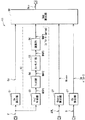
(画像処理部20)
画像処理部20は、ガンマ変換部21と、ピーク輝度伸長部22と、色域変換部23と、RGBW変換部24と、オーバーフロー補正部25と、ガンマ変換部26とを有している。
(Image processing unit 20)
The
ガンマ変換部21は、入力された画像信号Sp0を、線形なガンマ特性を有する画像信号Sp21に変換するものである。すなわち、外部から供給される画像信号は、一般的な表示装置の特性に合わせてガンマ値が例えば2.2等に設定され、非線形なガンマ特性を有している。よって、このガンマ変換部21は、画像処理部20での処理を容易にするため、このような非線形なガンマ特性を線形なガンマ特性に変換する。ガンマ変換部21は、例えばルックアップテーブル(LUT)を有しており、このルックアップテーブルを用いてこのようなガンマ変換を行うようになっている。
The
ピーク輝度伸長部22は、画像信号Sp21に含まれる輝度情報IR,IG,IBのピーク輝度を伸長することにより画像信号Sp22を生成するものである。
The peak
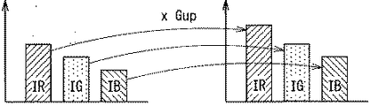
図5は、ピーク輝度伸長部22の一動作例を模式的に表すものである。ピーク輝度伸長部22は、各画素Pixに対応する3つの輝度情報IR,IG,IB(画素情報P)に基づいてゲインGupを求め、各輝度情報IR,IG,IBにそのゲインGupを乗算する。その際、後述するように、ゲインGupは、その3つの輝度情報IR,IG,IBが示す色が白色に近いほど、高くなるようになっている。これにより、ピーク輝度伸長部22は、色が白色に近いほど、輝度情報IR,IG,IBを伸長するように機能する。
FIG. 5 schematically illustrates an operation example of the peak
図6は、ピーク輝度伸長部22の一構成例を表すものである。ピーク輝度伸長部22は、明度取得部41と、平均輝度レベル取得部42と、ゲイン算出部43と、乗算部44とを有している。
FIG. 6 illustrates a configuration example of the peak
明度取得部41は、画像信号Sp21に含まれる輝度情報IR,IG,IBから、HSV色空間における明度Vを取得するものである。なお、この例では、HSV色空間における明度Vを取得するものとしたが、これに限定されるものではなく、これに代えて、例えばHSL色空間における輝度L(Luminance)を取得するように構成してもよいし、これらを選択可能に構成してもよい。
The
平均輝度レベル取得部42は、フレーム画像における輝度情報の平均値(平均輝度レベルAPL)を求めて出力するものである。
The average luminance
ゲイン算出部43は、明度取得部41から供給された画素情報Pごとの明度Vと、平均輝度レベル取得部42から供給されたフレーム画像ごとの平均輝度レベルAPLに基づいて、ゲインGupを算出するものである。
The
図7は、ゲイン算出部43の一構成例を表すものである。ゲイン算出部43は、Gv算出部91と、Garea算出部92と、Gbase算出部97と、Gup算出部98とを有している。
FIG. 7 illustrates a configuration example of the
Gv算出部91は、後述するように、明度Vに基づいてパラメータGvを算出するものである。このパラメータGvは、明度Vを用いて関数により得られるものである。
The
Garea算出部92は、明度Vに基づいて、パラメータGareaのマップを生成するものである。Garea算出部92は、マップ生成部93と、フィルタ部94と、スケーリング部95と、演算部96とを有している。
The
マップ生成部93は、各フレーム画像から得られた明度Vに基づいて、マップMAP1を生成するものである。具体的には、マップ生成部93は、フレーム画像の画像領域を、水平方向および垂直方向に複数(例えば60×30)のブロック領域Bに分け、ブロック領域Bごとの明度Vの平均値(領域輝度情報IA)を算出して、マップMAP1を生成するようになっている。この領域輝度情報IAは、そのブロック領域Bにおける明度Vの平均値を表すため、そのブロック領域Bにおいて、高い明度Vを有する画素情報Pが多いほど、すなわち明るい領域の面積が大きいほど、大きい値になるものである。
The
なお、この例では、マップ生成部93は、ブロック領域Bごとに明度Vの平均値を算出するものとしたが、これに限定されるものではなく、これに代えて、例えば、各ブロック領域Bにおける、明度Vが所定の値以上になるような画素情報Pの数を算出するようにしてもよい。
In this example, the
フィルタ部94は、マップMAP1に含まれる領域輝度情報IAを、ブロック領域B間で平滑化してマップMAP2を生成するものである。具体的には、フィルタ部94は、例えば5タップなどのFIR(Finite impulse response)フィルタにより構成されるものである。
The
スケーリング部95は、マップMAP2を、ブロック単位のマップから、画素情報P単位のマップに拡大スケーリングし、マップMAP3を生成するものである。すなわち、マップMAP3は、EL表示部13における画素Pixの数と同じ数の明度Vの情報を有するものである。その際、スケーリング部95は、例えば、線形補間や、バイキュービック補間などの補間処理により、この拡大スケーリングを行うようになっている。
The scaling
演算部96は、マップMAP3に基づいて、パラメータGareaについてのマップMAP4を生成するものである。この演算部96は、例えばルックアップテーブルを有しており、このルックアップテーブルを用いて、マップMAP3の各データに基づいて画素情報PごとのパラメータGareaを算出するようになっている。
The
Gbase算出部97は、平均輝度レベルAPLに基づいてパラメータGbaseを算出するものである。Gbase算出部97は、例えばルックアップテーブルを有しており、このルックアップテーブルを用いて、平均輝度レベルAPLに基づいて、後述するようにパラメータGbaseを算出するようになっている。
The
Gup算出部98は、後述するように、パラメータGv,Gbase,Gareaに基づいて、後述する所定の演算を行い、ゲインGupを算出するものである。
As will be described later, the
図6において、乗算部44は、輝度情報IR,IG,IBに、ゲイン算出部43によって算出されたゲインGupを乗算することにより、画像信号Sp22を生成するものである。
In FIG. 6, the
図1において、色域変換部23は、画像信号Sp22により表現される色域および色温度を、EL表示部13の色域および色温度に変換することにより、画像信号Sp23を生成するものである。具体的には、色域変換部23は、例えば3x3マトリックス変換などを行うことにより、色域および色温度変換を行うようになっている。なお、入力信号の色域と、EL表示部13の色域が一致している場合など、色域を変換する必要がない用途では、色温度を補正するための係数を用いて処理することにより、色温度の変換のみを行うようにしてもよい。
In FIG. 1, the color
RGBW変換部24は、RGB信号である画像信号Sp23に基づいて、RGBW信号を生成し、画像信号Sp24として出力するものである。具体的には、RGBW変換部24は、赤色(R)、緑色(G)、青色(B)の3色の輝度情報IR,IG,IBを含むRGB信号を、赤色(R)、緑色(G)、青色(B)、白色(W)の4色の輝度情報IR2,IG2,IB2,IW2を含むRGBW信号に変換するものである。
The
図8は、RGBW変換部24の一動作例を模式的に表すものである。RGBW変換部24は、まず、入力された3色の輝度情報IR,IG,IBのうちの最小のもの(この例では輝度情報IB)を輝度情報IW2とする。そして、RGBW変換部24は、輝度情報IRから輝度情報IW2を減算して輝度情報IR2を求め、輝度情報IGから輝度情報IW2を減算して輝度情報IG2を求め、輝度情報IBから輝度情報IW2を減算して輝度情報IB2(この例ではゼロ)を求める。そして、RGBW変換部24は、このようにして求めた輝度情報IR2,IG2,IB2,IW2を、RGBW信号として出力するようになっている。
FIG. 8 schematically illustrates an operation example of the
オーバーフロー補正部25は、画像信号Sp24に含まれる輝度情報IR2,IG2,IB2が、所定の輝度レベルを超えないように補正(オーバーフロー補正)を行い、画像信号Sp25として出力するものである。
The
図9は、オーバーフロー補正部25の一構成例を表すものである。オーバーフロー補正部25は、ゲイン算出部51R,51G,51Bと、増幅部52R,52G,52Bとを有している。ゲイン算出部51Rは、輝度情報IR2に基づいて、ゲインGRofを算出するものであり、増幅部52Rは、その輝度情報IR2にそのゲインGRofを乗算するものである。同様に、ゲイン算出部51Gは、輝度情報IG2に基づいて、ゲインGGofを算出するものであり、増幅部52Gは、その輝度情報IG2にそのゲインGGofを乗算するものである。また、ゲイン算出部51Bは、輝度情報IB2に基づいて、ゲインGBofを算出するものであり、増幅部52Bは、その輝度情報IB2にそのゲインGBofを乗算するものである。一方、オーバーフロー補正部25は、輝度情報IW2に対してはなんら処理を行わず、そのまま出力するようになっている。
FIG. 9 illustrates a configuration example of the
ゲイン算出部51R,51G,51Bは、後述するように、輝度情報IR2,IG2,IB2が所定の輝度レベルを超えないようにするためのゲインGRof,GGof,GBofをそれぞれ求める。そして、増幅部52R,52G,52Bは、輝度情報IR2,IG2,IB2に対して、このゲインGRof,GGof,GBofをそれぞれ乗算するようになっている。
As will be described later,
ガンマ変換部26は、線形なガンマ特性を有する画像信号Sp25を、EL表示部13の特性に対応した非線形なガンマ特性を有する画像信号Sp1に変換するものである。このガンマ変換部26は、ガンマ変換部21と同様に、例えばルックアップテーブルを有しており、このルックアップテーブルを用いてこのようなガンマ変換を行うようになっている。
The
ここで、乗算部44は、本開示における「決定部」の一具体例に対応する。色域変換部23およびRGBW変換部24は、本開示における「変換部」の一具体例に対応する。オーバーフロー補正部25は、本開示における「補正部」の一具体例に対応する。ゲインGupは、本開示における「第1のゲイン」の一具体例に対応する。明度Vは、本開示における「画素輝度値」の一具体例に対応する。画像信号Sp21は、本開示における「第1の輝度情報」の一具体例に対応し、画像信号Sp22は、本開示における「第2の輝度情報」の一具体例に対応し、画像信号Sp24は、本開示における「第3の輝度情報」の一具体例に対応し、画像信号Sp25は、本開示における「第4の輝度情報」の一具体例に対応する。
Here, the
[動作および作用]
続いて、本実施の形態の表示装置1の動作および作用について説明する。
[Operation and Action]
Subsequently, the operation and action of the display device 1 of the present embodiment will be described.
(全体動作概要)
まず、図1などを参照して、表示装置1の全体動作概要を説明する。入力部11は、外部機器から供給された画像信号に基づいて画像信号Sp0を生成する。ガンマ変換部21は、入力された画像信号Sp0を、線形なガンマ特性を有する画像信号Sp21に変換する。ピーク輝度伸長部22は、画像信号Sp21に含まれる輝度情報IR,IG,IBのピーク輝度を伸長することにより画像信号Sp22を生成する。色域変換部23は、画像信号Sp22により表現される色域および色温度を、EL表示部13の色域および色温度に変換することにより、画像信号Sp23を生成する。RGBW変換部24は、RGB信号である画像信号Sp23に基づいて、RGBW信号を生成し、画像信号Sp24として出力する。オーバーフロー補正部25は、画像信号Sp24に含まれる輝度情報IR2,IG2,IB2が、所定の輝度レベルを超えないように補正を行い、画像信号Sp25として出力する。ガンマ変換部26は、線形なガンマ特性を有する画像信号Sp25を、EL表示部13の特性に対応した非線形なガンマ特性を有する画像信号Sp1に変換する。表示制御部12は、画像信号Sp1に基づいて、EL表示部13での表示動作を制御する。EL表示部13は、表示制御部12による制御に基づいて表示動作を行う。
(Overview of overall operation)
First, the overall operation outline of the display device 1 will be described with reference to FIG. The
(ピーク輝度伸長部22)
次に、ピーク輝度伸長部22の詳細動作について説明する。ピーク輝度伸長部22では、明度取得部41が、画像信号Sp21に含まれる輝度情報IR,IG,IBから画素Pixごとの明度Vを取得し、平均輝度レベル取得部42が、フレーム画像における輝度情報の平均値(平均輝度レベルAPL)を求める。そして、ゲイン算出部43は、この明度Vおよび平均輝度レベルAPLに基づいてゲインGupを算出する。
(Peak luminance expansion part 22)
Next, the detailed operation of the peak
図10は、ゲイン算出部43のGv算出部91の動作を表すものである。Gv算出部91は、図10に示したように、明度Vに基づいてパラメータGvを算出する。パラメータGvは、この例では、明度Vが閾値Vth1以下では0(ゼロ)であり、閾値Vth1以上では傾きVsで一次関数的に増加するものである。すなわち、パラメータGvは、2つのパラメータ(閾値Vth1および傾きVs)により特定されるものである。
FIG. 10 illustrates the operation of the
また、ゲイン算出部43のGbase算出部97は、平均輝度レベルAPLに基づいてパラメータGbaseを算出する。このパラメータGbaseは、フレーム画像の平均輝度レベルAPLが高い(明るい)ほど小さく、平均輝度レベルAPLが低い(暗い)ほど大きいものである。Gbase算出部97は、平均輝度レベル取得部42から供給されたフレーム画像ごとの平均輝度レベルAPLに基づいて、このパラメータGbaseを求める。
Further, the
次に、Garea算出部92の動作について説明する。
Next, the operation of the
図11は、Garea算出部92の一動作例を表すものであり、(A)は表示装置1に入力されるフレーム画像Fを示し、(B)はマップMAP3を示し、(C)はパラメータGareaのマップMAP4を示す。図11(C)では、黒色はパラメータGareaが小さいことを示し、パラメータGareaが大きいほど白色になることを示している。
FIG. 11 shows an operation example of the
表示装置1では、まず、明度取得部41が、図11(A)に示したフレーム画像Fに基づいて、画素情報Pごとの明度Vを取得し、Garea算出部92に供給する。Garea算出部92では、まず、マップ生成部93が、ブロック領域Bごとの明度Vの平均値(領域輝度情報IA)を算出して、マップMAP1を生成する。領域輝度情報IAは、高い明度Vを有する画素情報Pが多いほど、すなわち明るい領域の面積が大きいほど、大きい値になるものであるため、マップMAP1は、明るい領域の面積を示すマップとなる。フィルタ部94は、このマップMAP1に含まれる領域輝度情報IAを、ブロック領域B間で平滑化してマップMAP2を生成する。
In the display device 1, first, the
次に、スケーリング部95は、マップMAP2に基づいて、補間処理により画素情報P単位のマップに拡大スケーリングし、マップMAP3(図11(B))を生成する。
Next, the scaling
次に、演算部96は、マップMAP3に基づいて、パラメータGareaについてのマップMAP4(図11(C))を生成する。
Next, the
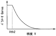
図12は、演算部96の動作を表すものである。演算部96は、図12に示したように、マップMAP3を構成する明度Vのそれぞれに基づいてパラメータGareaを算出する。パラメータGareaは、この例では、明度Vが閾値Vth2以下では一定値であり、閾値Vth2以上では明度Vが増加するにつれて減少するものである。
FIG. 12 shows the operation of the
演算部96は、このように、マップMAP3を構成する明度Vのそれぞれに基づいてパラメータGareaを算出し、マップMAP4(図11(C))を生成する。このマップMAP4(図11(C))では、フレーム画像F(図11(A))において、明るい領域の面積が大きいほどパラメータGareaは小さくなり(黒色で表示)、明るい領域の面積が小さいほどパラメータGareaが大きくなる(白色で表示)。
In this way, the
Gup算出部98は、このようにして得られた3つのパラメータGv,Gbase,Gareaに基づいて、以下の式(1)を用いて、画素情報PごとにゲインGupを算出する。
Gup=(1+Gv×Garea)×Gbase ・・・(1)
The
Gup = (1 + Gv × Garea) × Gbase (1)
図13は、ゲインGupの特性を表すものである。この図13では、平均輝度レベルAPLが一定(パラメータGbaseが一定)の条件において、その平均輝度レベルAPLが大きい場合と小さい場合の2つの特性を示している。なお、この例では、説明の便宜上、パラメータGareaは一定としている。ゲインGupは、図13に示したように、明度Vが閾値Vth1よりも低い場合には一定値となり、明度Vが閾値Vth1よりも高い場合には、明度Vが高いほど大きくなる。すなわち、ゲインGupは、その輝度情報IR,IG,IBが示す色が白色に近いほど高くなる。また、平均輝度レベルAPLが小さい場合には、パラメータGbaseが大きくなるため、ゲインGupは大きくなり、反対に、平均輝度レベルAPLが大きい場合には、パラメータGbaseが小さくなるため、ゲインGupは小さくなる。 FIG. 13 shows the characteristics of the gain Gup. FIG. 13 shows two characteristics when the average luminance level APL is large and small when the average luminance level APL is constant (parameter Gbase is constant). In this example, the parameter Garea is constant for convenience of explanation. As shown in FIG. 13, the gain Gup has a constant value when the brightness V is lower than the threshold value Vth1, and increases as the brightness V increases when the brightness V is higher than the threshold value Vth1. That is, the gain Gup increases as the color indicated by the luminance information IR, IG, IB is closer to white. Further, when the average luminance level APL is small, the parameter Gbase increases, so the gain Gup increases. Conversely, when the average luminance level APL is large, the parameter Gbase decreases, so the gain Gup decreases. .
図14は、ピーク輝度伸長部22の一動作例を表すものである。この図14は、図13において、平均輝度レベルAPLが小さい場合の明度V1〜V3における動作を示しており、図14(A)は明度V1の場合を示し、図14(B)は明度V2の場合を示し、図14(C)は明度V3の場合を示す。図13に示したように、明度Vが閾値Vth1以下である場合には、ゲインGupはゲインG1で一定であるため、図14(A),(B)に示したように、ピーク輝度伸長部22は、輝度情報IR,IG,IBに同じゲインG1で乗算する。一方、図13に示したように、明度Vが閾値Vth1以上である場合には、ゲインGupが高くなるため、図14(C)に示したように、ピーク輝度伸長部22は、輝度情報IR,IG,IBに、ゲインG1よりも大きいゲインG2を乗算する。
FIG. 14 shows an operation example of the peak
このように、ピーク輝度伸長部22は、明度Vが高いほどゲインGupを高くすることにより、輝度を伸長する。これにより、画像信号のダイナミックレンジを高くすることができる。よって、表示装置1は、例えば、夜空に星がまたたくような画像を表示する際には、星をより明るく表示することができ、また、コインなどの金属を表示する場合には、その金属の光沢を表現できるなど、コントラストが高い画像を表示することができる。
As described above, the peak
また、図13に示したように、表示装置1では、明度Vがしきい値Vth1以下である場合にはゲインGupを一定値とし、明度Vがしきい値Vth1以上である場合にゲインGupを高くしたので、表示画像が暗くなるおそれを低減することができる。すなわち、例えば特許文献1に開示された表示装置では、ピーク輝度を伸長するとともに、低階調の輝度を下げるようにガンマ特性を変化させるため、表示画像のうち、ピーク輝度の伸長に係る部分以外の部分において、画像が暗くなり、画質が低下するおそれがある。一方、表示装置1では、明度Vがしきい値Vth1以下である場合にはゲインGupを一定値としたので、ピーク輝度の伸長に係る部分以外の部分について画像が暗くなることがないため、画質の低下を抑えることができる。 Further, as shown in FIG. 13, in the display device 1, the gain Gup is set to a constant value when the brightness V is equal to or less than the threshold value Vth1, and the gain Gup is set to when the brightness V is equal to or greater than the threshold value Vth1. Since the height is increased, it is possible to reduce the possibility that the display image becomes dark. That is, for example, in the display device disclosed in Patent Literature 1, the peak luminance is expanded and the gamma characteristic is changed so as to decrease the luminance of low gradation. In this part, the image becomes dark and the image quality may be deteriorated. On the other hand, in the display device 1, when the lightness V is equal to or less than the threshold value Vth1, the gain Gup is set to a constant value, so that the image does not become dark in portions other than the portion related to the peak luminance expansion. Can be suppressed.
また、表示装置1では、平均輝度レベルAPLに基づいてゲインGupが変化するようにしたので、画質を高めることができる。すなわち、例えば、表示画面が暗い場合には、観察者の眼の順応輝度が低いため、観察者は、表示画面内の輝度レベルが高い部分における輝度レベルの階調の違いを感じにくくなっている。一方、表示画面が明るい場合には、観察者の眼の順応輝度が高いため、観察者は、表示画面内の輝度レベルが高い部分における輝度レベルの階調の違いを感じやすい。表示装置1では、平均輝度レベルAPLに基づいてゲインGupが変化するようにしたので、例えば、表示画面が暗い場合(平均輝度レベルAPLが低い場合)には、ゲインGupを大きくすることにより、輝度レベルの階調の違いを感じやすくし、表示画面が明るい場合(平均輝度レベルAPLが大きい場合)には、ゲインGupを小さくすることにより、輝度レベルの階調の違いを過度に感じないようにしている。 In the display device 1, the gain Gup is changed based on the average luminance level APL, so that the image quality can be improved. That is, for example, when the display screen is dark, the adaptation brightness of the observer's eyes is low, so the observer is less likely to perceive a difference in luminance level gradation in a portion with a high luminance level in the display screen. . On the other hand, when the display screen is bright, the adaptation brightness of the observer's eyes is high, and thus the observer can easily feel the difference in gradation of the brightness level in the portion with the high brightness level in the display screen. In the display device 1, the gain Gup is changed based on the average luminance level APL. For example, when the display screen is dark (when the average luminance level APL is low), the gain Gup is increased to increase the luminance. Makes it easy to feel the difference in the gradation of the level, and when the display screen is bright (when the average luminance level APL is large), the gain Gup is reduced so that the difference in the gradation of the luminance level is not excessively felt. ing.
また、表示装置1では、パラメータGareaに基づいてゲインGupが変化するようにしたので、以下に示すように、画質を高めることができる。 In the display device 1, since the gain Gup is changed based on the parameter Garea, the image quality can be improved as described below.
図15は、表示画面の一例を表すものである。この例では、夜空に満月Y1、および複数の星Y2がある画像を表示している。仮に、ゲイン算出部43が、パラメータGareaを用いずにゲインGupを算出する場合には、ピーク輝度伸長部22は、この例では、この満月Y1を構成する輝度情報IR,IG,IBと、星Y2を構成する輝度情報IR,IG,IBの両方に対してピーク輝度を伸長する。しかしながら、観察者は、表示面積の大きい満月Y1についてはより輝きを増したと感じる一方、星Y2については、それらの面積が小さいため、その効果を感じにくいおそれがある。
FIG. 15 shows an example of a display screen. In this example, an image having a full moon Y1 and a plurality of stars Y2 in the night sky is displayed. If the
また、例えば特許文献1に開示された表示装置において、図15に示したような画像を表示させる場合には、明るい領域の面積が大きい満月Y1により、画面全体としてピーク輝度の伸長が抑制されてしまうおそれがある。 Further, in the display device disclosed in Patent Document 1, for example, when an image as shown in FIG. 15 is displayed, expansion of peak luminance as a whole screen is suppressed by the full moon Y1 having a large bright area. There is a risk that.
一方、表示装置1では、パラメータGareaに基づいてゲインGupが変化するようにしている。具体的には、フレーム画像において、明るい領域の面積が大きいほどパラメータGareaは小さくなり、式(1)によりゲインGupが小さくなる。同様に、明るい領域の面積が小さいほどパラメータGareaが大きくなり、式(1)によりゲインGupが大きくなる。これにより、図15の例では、満月Y1では、明るい領域の面積が大きいため、パラメータGareaが小さくなることによりピーク輝度の伸長が抑制され、星Y2では、明るい領域の面積が小さいため、ピーク輝度が伸長される。よって、星Y2の部分での輝度が相対的に高くなるため、画質を高めることができる。 On the other hand, in the display device 1, the gain Gup is changed based on the parameter Garea. Specifically, in the frame image, the larger the area of the bright region, the smaller the parameter Garea, and the gain Gup is reduced according to the equation (1). Similarly, the smaller the area of the bright region, the larger the parameter Garea, and the gain Gup increases according to the equation (1). Accordingly, in the example of FIG. 15, since the area of the bright region is large in the full moon Y1, the expansion of the peak luminance is suppressed by decreasing the parameter Garea, and in the star Y2, the area of the bright region is small, so that the peak luminance is Is expanded. Therefore, the luminance at the portion of the star Y2 becomes relatively high, so that the image quality can be improved.
次に、画像処理部20における処理順序について説明する。
Next, the processing order in the
表示装置1では、ピーク輝度伸長部22の後段に色域変換部23を設け、ピーク輝度を伸長した画像信号Sp22の色域および色温度を、EL表示部13の色域および色温度に変換するようにしたので、画質の低下を抑えることができる。すなわち、仮に、色域変換部23の後段にピーク輝度伸長部22を設けた場合には、ピーク輝度伸長部22は、色域変換後の輝度情報の明度Vに基づいてゲインGupを算出することになるため、例えばピーク輝度を伸長する対象(色度の範囲)が変化してしまい、画質が低下するおそれがある。一方、表示装置1では、ピーク輝度伸長部22の後段に色域変換部23を設けるようにしたので、このようにピーク輝度を伸長する対象(色度の範囲)が変化することがないため、画質の低下を抑えることができる。
In the display device 1, a color
また、表示装置1では、ピーク輝度伸長部22の後段にRGBW変換部24を設け、ピーク輝度を伸長した輝度情報IR,IG,IBを含むRGB信号を、RGBW変換するようにしたので、画質の低下を抑えることができる。すなわち、一般に、EL表示部13の各サブ画素SPixは、信号レベルに依存して色度が変化するおそれがある。よって、仮に、RGBW変換部24の後段にピーク輝度伸長部22を設けた場合には、表示画像の色度がずれるおそれがあり、これを避けるために画像処理を行う場合には、非線形性を考慮した複雑な処理を行う必要がある。一方、表示装置1では、ピーク輝度伸長部22の後段にRGBW変換部24を設けるようにしたので、表示画像の色度がずれるおそれを低減することができる。
In the display device 1, the
また、表示装置1では、Garea算出部92(図7)において、フィルタ部94の後段にスケーリング部94を設け、平滑化したマップMAP2に基づいて拡大スケーリングすることによりマップMAP4を生成するようにしたので、マップMAP4におけるデータをより滑らかにすることができ、画質の低下を抑えることができる。
Further, in the display device 1, the Garea calculation unit 92 (FIG. 7) includes a
また、表示装置1では、スケーリング部95の後段に演算部96を設け、拡大スケーリング後のマップMAP3に基づいて、演算部96がパラメータGareaを求めるようにしたので、以下に示すように、画質の低下を抑えることができる。
In the display device 1, the
図16は、図11(C)の線分W1におけるパラメータGareaを表すものであり、(A)はスケーリング部95の後段に演算部96を設けた場合を示し、(B)は一例としてスケーリング部95の前段に演算部96を設けた場合を示す。スケーリング部95の後段に演算部96を設けた場合(図16(A))には、スケーリング部95の前段に演算部96を設けた場合(図16(B))に比べ、例えば部分W2などにおいて、パラメータGareaをより滑らかにすることができる。
FIG. 16 shows the parameter Garea in the line segment W1 of FIG. 11C, where FIG. 16A shows the case where the
これは、以下の理由によると考えられる。すなわち、演算部96が、図12に示したように、明度Vに基づいてパラメータGareaを求める際には、図12の特性線の勾配が高い部分において、変換後のパラメータGareaが粗くなるおそれがある。よって、スケーリング部95の前段に演算部96を設けた場合には、このように粗くなったパラメータGareaに基づいて拡大スケーリングが行われるため、誤差が伝搬し、図16(B)に示したように、例えば部分W3などにおいて滑らかさが低下するおそれがある。一方、表示装置1では、スケーリング部95の後段に演算部96を設けたので、誤差が伝搬するおそれを低減することができるため、図16(A)に示したように、パラメータGareaをより滑らかにすることができる。これにより、表示装置1では、画質の低下を抑えることができる。
This is considered to be due to the following reason. That is, as shown in FIG. 12, when the
(オーバーフロー補正部25)
次に、オーバーフロー補正部25におけるオーバーフロー補正について詳細に説明する。オーバーフロー補正部25では、ゲイン算出部51R,51G,51Bは、輝度情報IR2,IG2,IB2が所定の最大輝度レベルを超えないようなゲインGRof,GGof,GBofをそれぞれ求め、増幅部52R,52G,52Bは、輝度情報IR2,IG2,IB2にこのゲインGRof,GGof,GBofをそれぞれ乗算する。
(Overflow correction unit 25)
Next, the overflow correction in the
図17は、オーバーフロー補正部25の一動作例を表すものであり、(A)はゲイン算出部51R,51G,51Bの動作を示し、(B)は増幅部52R,52G,52Bの動作を示す。以下、説明の便宜上、輝度情報IR2に対する処理を例に説明する。なお、輝度情報IG2,IB2に対する処理も全く同様である。
FIG. 17 illustrates an operation example of the
図17(A)に示したように、ゲイン算出部51Rは、輝度情報IR2に基づいて、ゲインGRofを算出する。その際、ゲイン算出部51Rは、輝度情報IR2が所定の輝度値Ithよりも低い場合にはゲインGRofを“1”に設定し、輝度情報IR2がこの輝度値Ithよりも高い場合には、輝度情報IR2が大きいほど低いゲインGRofを設定する。
As shown in FIG. 17A, the
増幅部52Rが、輝度情報IR2にこのゲインGRofを乗算すると、図17(B)に示したように、増幅部52Rから出力される輝度情報IR2(補正後の輝度情報IR2)は、輝度値Ithより大きくなると、徐々に所定の輝度レベルImax(この例では1024)に飽和する。
When the
このように、オーバーフロー補正部25は、輝度情報IR2,IG2,IB2が所定の輝度レベルImaxを超えないように補正を行っている。これにより、画像が乱れるおそれを低減することができる。すなわち、表示装置1では、RGBW変換部24がRGBW変換を行うことにより輝度情報IR2,IG2,IB2,IW2を生成し、EL表示部13はこれらに基づいて表示を行う。その際、RGBW変換部24が、EL表示部13が表示出来ないような過大な輝度情報IR2,IG2,IB2を生成するおそれがある。このような過大な輝度情報IR2,IG2,IB2に基づいてEL表示部13が表示を行った場合には、輝度が高い部分を適切に表示することができないため、画像が乱れるおそれがある。一方、表示装置1では、オーバーフロー補正部25を設け、輝度情報IR2,IG2,IB2が、輝度レベルImaxを超えないように補正を行うようにしたので、このように画像が乱れるおそれを低減することができる。
As described above, the
[効果]
以上のように本実施の形態では、ピーク輝度伸長部は、輝度情報の明度が高いほどゲインGupが高くなるように設定したので、コントラストを高めることができるため、画質を高めることができる。
[effect]
As described above, in the present embodiment, the peak luminance expansion unit is set so that the gain Gup increases as the brightness of the luminance information increases. Therefore, the contrast can be increased, and the image quality can be improved.
また、本実施の形態では、平均輝度レベルに基づいてゲインGupが変化するようにしたので、観察者の眼の順応輝度に応じてピーク輝度の伸長を調整することができるため、画質を高めることができる。 In this embodiment, since the gain Gup is changed based on the average luminance level, the extension of the peak luminance can be adjusted according to the adaptation luminance of the observer's eyes, so that the image quality is improved. Can do.
また、本実施の形態では、明るい領域の面積に応じてゲインGupが変化するようにしたので、明るい領域の面積が大きい部分に対してはピーク輝度の伸長を抑制し、明るい領域の面積が小さい部分の輝度を相対的に上昇することができるため、画質を高めることができる。 In the present embodiment, the gain Gup is changed in accordance with the area of the bright region. Therefore, the peak luminance is suppressed from being increased in the portion where the area of the bright region is large, and the area of the bright region is small. Since the luminance of the portion can be relatively increased, the image quality can be improved.
また、本実施の形態では、ピーク輝度伸長部の後段に色域変換部やRGBW変換部を設けたので、画質の低下を抑えることができる。 Further, in the present embodiment, since the color gamut conversion unit and the RGBW conversion unit are provided after the peak luminance expansion unit, it is possible to suppress deterioration in image quality.
また、本実施の形態では、オーバーフロー補正部を設け、輝度情報が所定の輝度レベルを超えないように補正を行うようにしたので、画質の低下を抑えることができる。 In the present embodiment, since an overflow correction unit is provided and correction is performed so that the luminance information does not exceed a predetermined luminance level, deterioration in image quality can be suppressed.
また、本実施の形態では、Garea算出部において、フィルタ部の後段にスケーリング部を設け、平滑化したマップMAP2に基づいて拡大スケーリングするようにしたので、画質の低下を抑えることができる。 In the present embodiment, since the Garea calculation unit is provided with a scaling unit after the filter unit and is scaled up based on the smoothed map MAP2, it is possible to suppress degradation in image quality.
また、本実施の形態では、Garea算出部において、スケーリング部の後段に演算部を設け、を設け、拡大スケーリング後のマップMAP3に基づいてパラメータGareaを求めるようにしたので、画質の低下を抑えることができる。 Further, in the present embodiment, the Garea calculation unit is provided with a calculation unit after the scaling unit, and the parameter Garea is obtained based on the map MAP3 after the enlarged scaling. Can do.
[変形例1−1]
上記実施の形態では、オーバーフロー補正部25は、輝度情報IR2,IG2,IB2ごとにゲインGRof,GGof,GBofを算出したが、これに限定されるものではなく、これに代えて、例えば、図18に示したように、輝度情報IR2,IG2,IB2に基づいて、共通のゲインGofを算出してもよい。以下に、本変形例に係るオーバーフロー補正部25Bについて、詳細に説明する。
[Modification 1-1]
In the above embodiment, the
オーバーフロー補正部25Bは、図18に示したように、最大輝度検出部53と、ゲイン算出部54と、増幅部52Wを有している。最大輝度検出部53は、各輝度情報IR2,IG2,IB2のうちの最大のものを検出するものである。ゲイン算出部54は、最大輝度検出部53が検出した最大の輝度情報に基づいて、オーバーフロー補正部25の場合(図17)と同様にゲインGofを算出するものである。増幅部52R,52G,52B,52Wは、輝度情報IR2,IG2,IB2,IW2に、このゲインGofを乗算するものである。
As shown in FIG. 18, the overflow correction unit 25B includes a maximum
本変形例に係るオーバーフロー補正部25Bは、輝度情報IR2,IG2,IB2,IW2に対して共通のゲインGofを乗算する。これにより、色度ずれが生じるおそれを低減することができる。一方、上記実施の形態に係るオーバーフロー補正部25は、輝度情報IR2,IG2,IB2ごとにゲインGRof,GGof,GBofを算出したので、表示画像を明るくすることができる。
The overflow correction unit 25B according to this modification multiplies the luminance information IR2, IG2, IB2, and IW2 by a common gain Gof. Thereby, the possibility that chromaticity deviation may occur can be reduced. On the other hand, since the
[変形例1−2]
上記実施の形態では、ピーク輝度伸長部22は、パラメータGvを、明度Vを用いて関数により得るようにしたが、これに限定されるものではなく、これに代えて、例えば、明度Vを用いてルックアップテーブルにより得てもよい。この場合には、パラメータGvと明度Vとの関係を、例えば図19に示したように、より自由に設定することができる。
[Modification 1-2]
In the above embodiment, the peak
[変形例1−3]
上記実施の形態では、ピーク輝度伸長部22は、明度Vに基づいてパラメータGvを算出する際のしきい値Vth1を固定値としたが、これに限定されるものではなく、これに代えて、例えば、図20に示したように、平均輝度レベルAPLが低い場合にはしきい値Vth1を下げ、平均輝度レベルAPLが高い場合にはしきい値Vth1を上げるようにしてもよい。これにより、図21に示したように、平均輝度レベルAPLが低い場合には、明度Vが低いところからゲインGupを増加させることができ、一方、平均輝度レベルAPLが高い場合には、明度Vが高いところからゲインGupを増加させることができ、観察者の眼の順応輝度の変化による感度の変化を補うことができる。
[Modification 1-3]
In the above embodiment, the peak
<2.第2の実施の形態>
次に、第2の実施の形態に係る表示装置2について説明する。本実施の形態は、ピーク輝度を伸長する際に、オーバーフロー補正をも行うものである。なお、上記第1の実施の形態に係る表示装置1と実質的に同一の構成部分には同一の符号を付し、適宜説明を省略する。
<2. Second Embodiment>
Next, the
図22は、本実施の形態に係る表示装置2の一構成例を表すものである。表示装置2は、ピーク輝度伸長部62を有する画像処理部60を備えている。ピーク輝度伸長部62は、ピーク輝度の伸長処理を行うとともに、オーバーフロー補正をも行い、画像信号Sp62を生成するものである。すなわち、このピーク輝度伸長部62は、上記第1の実施の形態に係る表示装置1において、オーバーフロー補正部25が行っていたオーバーフロー補正を、RGBW変換前にあらかじめ行うものである。
FIG. 22 illustrates a configuration example of the
図23は、ピーク輝度伸長部62の一構成例を表すものである。ピーク輝度伸長部62は、彩度取得部64と、ゲイン算出部63とを有している。彩度取得部64は、画像信号Sp21に含まれる輝度情報IR,IG,IBから、HSV色空間における彩度Sを画素情報Pごとに取得するものである。ゲイン算出部63は、この彩度取得部64が取得した彩度S、明度取得部41が取得した明度V、および平均輝度レベル取得部42が取得した平均輝度レベルAPLに基づいてゲインGupを算出するものである。
FIG. 23 illustrates a configuration example of the peak
図24は、ゲイン算出部63の一構成例を表すものである。ゲイン算出部63は、Gs算出部67と、Gup算出部68とを備えている。
FIG. 24 illustrates a configuration example of the
Gs算出部67は、彩度Sに基づいてパラメータGsを算出するものである。Gs算出部67は、例えばルックアップテーブルを有しており、このルックアップテーブルを用いて、彩度Sに基づいて、パラメータGsを算出するようになっている。
The
図25は、Gs算出部67の動作を表すものである。Gs算出部67は、図25に示したように、彩度Sに基づいてパラメータGsを算出する。パラメータGsは、この例では、彩度Sが大きくなるほど減少するものである。
FIG. 25 shows the operation of the
Gup算出部68は、パラメータGv,Gbase,Garea,Gsに基づいて、以下の式(2)を用いて、ゲインGupを算出する。
Gup=(1+Gv×Garea×Gs)×Gbase ・・・(2)
The
Gup = (1 + Gv × Garea × Gs) × Gbase (2)
このように、表示装置2では、彩度Sが大きいほどパラメータGsが小さくなり、その結果、ゲインGupが小さくなるため、上述したオーバーフロー補正と同等の効果を得ることができる。
As described above, in the
以上のように本実施の形態では、パラメータGsを設け、彩度によりゲインGupが変化するようにしたので、ピーク輝度伸長部が、ピーク輝度の伸長を行うとともにオーバーフロー補正をも行うことができる。その他の効果は、上記第1の実施の形態の場合と同様である。 As described above, in the present embodiment, the parameter Gs is provided, and the gain Gup is changed according to the saturation. Therefore, the peak luminance extending unit can perform the peak correction and the overflow correction. Other effects are the same as in the case of the first embodiment.
[変形例2−1]
上記実施の形態に係る表示装置2に、上記第1の実施の形態の変形例1−1〜1−3を適用してもよい。
[Modification 2-1]
Modifications 1-1 to 1-3 of the first embodiment may be applied to the
<3.第3の実施の形態>
次に、第3の実施の形態に係る表示装置3について説明する。本実施の形態は、表示素子として液晶表示素子を用い、液晶表示装置として構成したものである。なお、上記第1の実施の形態に係る表示装置1等と実質的に同一の構成部分には同一の符号を付し、適宜説明を省略する。
<3. Third Embodiment>
Next, a display device 3 according to a third embodiment will be described. In this embodiment, a liquid crystal display element is used as a display element, and the liquid crystal display device is configured. In addition, the same code | symbol is attached | subjected to the component substantially the same as the display apparatus 1 etc. which concern on the said 1st Embodiment, and description is abbreviate | omitted suitably.
図26は、表示装置3の一構成例を表すものである。表示装置3は、画像処理部70と、表示制御部14と、液晶表示部15と、バックライト制御部16と、バックライト17とを備えている。
FIG. 26 illustrates a configuration example of the display device 3. The display device 3 includes an
画像処理部70は、バックライトレベル算出部71と、輝度情報変換部72とを有している。バックライトレベル算出部71および輝度情報変換部72は、以下に説明するように、表示装置3の消費電力を低減することができる、いわゆるディミング機能を実現するために設けられたものである。ディミング機能については、例えば、特開2012−27405に記載がある。
The
バックライトレベル算出部71は、画像信号Sp22に基づいて、バックライト17の発光輝度を示すバックライトレベルBLを算出するものである。具体的には、バックライトレベル算出部71は、例えば、各フレーム画像における輝度情報IR,IG,IBのピーク値を求め、そのピーク値が大きいほどバックライト17の発光輝度が高くなるようにバックライトレベルBLを算出する。
The backlight
輝度情報変換部72は、画像信号Sp22に含まれる輝度情報IR,IG,IBを、バックライトレベルBLで除算することにより変換し、画像信号Sp72を生成するものである。
The luminance
表示制御部14は、画像信号Sp1に基づいて、液晶表示部15での表示動作を制御するものである。液晶表示部15は、表示素子として液晶表示素子を用いた表示部であり、表示制御部14による制御に基づいて表示動作を行うものである。
The
バックライト制御部16は、バックライトレベルBLに基づいて、バックライト17における発光を制御するものである。バックライト17は、バックライト制御部16による制御に基づいて発光し、液晶表示部15に対してその光を射出するものである。バックライト17は、例えば、LED(Light Emitting Diode)を用いて構成されるものである。
The
この構成により、表示装置3では、バックライトレベル算出部71および輝度情報変換部72が、輝度情報IR,IG,IBに応じてバックライト17の発光輝度を調整する。これにより、表示装置3では、消費電力を低減することができる。
With this configuration, in the display device 3, the backlight
また、表示装置3では、ピーク輝度伸長部22の後段に、バックライトレベル算出部71および輝度情報変換部72を設け、ピーク輝度を伸長した画像信号Sp22に基づいてバックライトレベルBLを算出するとともに輝度情報IR,IG,IBを変換している。これにより、画面全体を暗くすることなく、ピーク輝度のみ伸長することができる。
In the display device 3, a backlight
以上のように、本技術を液晶表示装置に適用しても、上記第1の実施の形態の場合などと同様の効果を実現することができる。 As described above, even when the present technology is applied to the liquid crystal display device, it is possible to achieve the same effect as in the case of the first embodiment.
[変形例3−1]
上記実施の形態に係る表示装置3に、上記第1の実施の形態の変形例1−1〜1−3、上記第2の実施の形態、およびその変形例2−1を適用してもよい。
[Modification 3-1]
Modifications 1-1 to 1-3 of the first embodiment, the second embodiment, and modification 2-1 of the first embodiment may be applied to the display device 3 according to the embodiment. .
<4.第4の実施の形態>
次に、第4の実施の形態に係る表示装置4について説明する。本実施の形態は、赤色、緑色、青色の3色のサブ画素SPixからなる画素Pixを用いてEL表示部を構成したものである。なお、上記第1の実施の形態に係る表示装置1等と実質的に同一の構成部分には同一の符号を付し、適宜説明を省略する。
<4. Fourth Embodiment>
Next, a
図27は、表示装置4の一構成例を表すものである。表示装置4は、EL表示部13Aと、表示制御部12Aと、画像処理部80とを備えている。
FIG. 27 illustrates a configuration example of the
図28は、EL表示部13Aの一構成例を表すものである。EL表示部13Aは、画素アレイ部33Aと、垂直駆動部31Aと、水平駆動部32Aとを有している。画素アレイ部33Aは、画素Pixがマトリックス状に配置されたものである。この例では、各画素は、垂直方向Yに延伸する、赤色(R)、緑色(G)、および青色(B)の3つのサブ画素SPixにより構成されている。この例では、画素Pixにおいて、左から、赤色(R)、緑色(G)、青色(B)のサブ画素SPixを順に配置している。垂直駆動部31Aおよび水平駆動部32Aは、表示制御部12Aによるタイミング制御に基づいて、画素アレイ部33Aを駆動するものである。
FIG. 28 illustrates a configuration example of the
表示制御部12Aは、このようなEL表示部13Aでの表示動作を制御するものである。
The
画像処理部80は、図27に示したように、ガンマ変換部21と、ピーク輝度伸長部82と、色域変換部23と、ガンマ変換部26を有するものである。すなわち、画像処理部80は、上記第1の実施の形態に係る画像処理部20(図1)において、ピーク輝度伸長部22をピーク輝度伸長部82に置き換えるとともに、RGBW変換部24およびオーバーフロー補正部25を省いたものである。
As illustrated in FIG. 27, the image processing unit 80 includes a
図29は、ピーク輝度伸長部82の一構成例を表すものである。ピーク輝度伸長部82は、乗算部81を有している。乗算部81は、画像信号Sp21に含まれる輝度情報IR,IG,IBに対して、共通の1以下のゲインGpre(例えば0.8など)を乗算し、画像信号Sp81を生成するものである。明度取得部41、平均輝度レベル42、ゲイン算出部43、および乗算部44は、上記第1の実施の形態の場合と同様に、この画像信号Sp81に含まれる輝度情報IR,IG,IBのピーク輝度を伸長するようになっている。
FIG. 29 illustrates a configuration example of the peak
表示装置4では、このように、あらかじめ輝度情報IR,IG,IBを小さくした後、上記第1の実施の形態の場合と同様に、そのピーク輝度を伸長する。その際、輝度情報IR,IG,IBを小さくした分だけ、ピーク輝度を伸長することができるため、ダイナミックレンジを維持しつつピーク輝度を伸長することができる。
In the
また、表示装置4では、上記第1の実施の形態の場合と同様に、明るい領域の面積に応じてゲインGupが変化するため、明るい領域の面積が大きい部分に対してはピーク輝度の伸長を抑制し、明るい領域の面積が小さい部分の輝度を相対的に上昇することができるため、画質を高めることができる。
Further, in the
以上のように、本技術を、3色のサブ画素を有するEL表示装置に適用しても、上記第1の実施の形態の場合などと同様の効果を実現することができる。 As described above, even if the present technology is applied to an EL display device having sub-pixels of three colors, the same effect as in the case of the first embodiment can be realized.
[変形例4−1]
上記実施の形態に係る表示装置4に、上記第1の実施の形態の変形例1−1〜1−3、上記第2の実施の形態、およびその変形例2−1を適用してもよい。
[Modification 4-1]
Modifications 1-1 to 1-3 of the first embodiment, the second embodiment, and modification 2-1 of the first embodiment may be applied to the
<5.適用例>
次に、上記実施の形態および変形例で説明した表示装置の適用例について説明する。
<5. Application example>
Next, application examples of the display device described in the above embodiment and modifications will be described.
図30は、上記実施の形態等の表示装置が適用されるテレビジョン装置の外観を表すものである。このテレビジョン装置は、例えば、フロントパネル511およびフィルターガラス512を含む映像表示画面部510を有している。このテレビジョン装置は、上記実施の形態等に係る表示装置を含んで構成されている。
FIG. 30 illustrates an appearance of a television device to which the display device of the above-described embodiment or the like is applied. The television apparatus includes a video display screen unit 510 including a front panel 511 and a
上記実施の形態等の表示装置は、このようなテレビジョン装置の他、デジタルカメラ、ノート型パーソナルコンピュータ、携帯電話等の携帯端末装置、携帯型ゲーム機、あるいはビデオカメラなどのあらゆる分野の電子機器に適用することが可能である。言い換えると、上記実施の形態等の表示装置は、映像を表示するあらゆる分野の電子機器に適用することが可能である。 The display device according to the above embodiment includes electronic devices in various fields such as a digital camera, a notebook personal computer, a portable terminal device such as a mobile phone, a portable game machine, or a video camera in addition to such a television device. It is possible to apply to. In other words, the display device of the above embodiment and the like can be applied to electronic devices in all fields that display video.
以上、いくつかの実施の形態および変形例、ならびに電子機器への適用例を挙げて本技術を説明したが、本技術はこれらの実施の形態等には限定されず、種々の変形が可能である。 The present technology has been described above with some embodiments and modifications, and application examples to electronic devices. However, the present technology is not limited to these embodiments and the like, and various modifications are possible. is there.
例えば、上記の第1〜第3の各実施の形態等では、EL表示部13の画素アレイ部33において、4つのサブ画素SPixを2行2列で配置して画素Pixを構成したが、これに限定されるものではなく、図31に示したように、垂直方向Yに延伸する4つのサブ画素SPixを水平方向Xに並設することにより画素Pixを構成してもよい。この例では、画素Pixにおいて、左から、赤色(R)、緑色(G)、青色(B)、白色(W)のサブ画素SPixを順に配置している。
For example, in each of the first to third embodiments described above, the pixel Pix is configured by arranging the four subpixels SPix in two rows and two columns in the pixel array unit 33 of the
なお、本技術は以下のような構成とすることができる。 In addition, this technique can be set as the following structures.
(1)画素ごとの第1の輝度情報に基づいて第1のゲインを求めるゲイン算出部と、
前記第1の輝度情報と前記第1のゲインとに基づいて、画素ごとの第2の輝度情報を決定する決定部と、
前記第2の輝度情報に基づいて表示を行う表示部と
を備え、
前記第1のゲインは、前記第1の輝度情報から導かれる画素輝度値が所定の輝度値以上の領域において、前記画素輝度値がより大きいほどより大きい
表示装置。
(1) a gain calculation unit that obtains a first gain based on first luminance information for each pixel;
A determination unit that determines second luminance information for each pixel based on the first luminance information and the first gain;
A display unit that performs display based on the second luminance information,
The first gain is larger as the pixel luminance value is larger in a region where the pixel luminance value derived from the first luminance information is equal to or higher than a predetermined luminance value.
(2)前記ゲイン算出部は、前記画素輝度値と前記第1のゲインとの関係を表すゲイン関数に基づいて前記第1のゲインを求め、
前記ゲイン関数において、前記第1のゲインは、前記所定の輝度値以上の前記画素輝度値に対して所定の傾きで増加する
前記(1)に記載の表示装置。
(2) The gain calculation unit obtains the first gain based on a gain function representing a relationship between the pixel luminance value and the first gain,
The display device according to (1), wherein in the gain function, the first gain increases with a predetermined inclination with respect to the pixel luminance value equal to or greater than the predetermined luminance value.
(3)前記所定の輝度値は、フレーム画像における前記第1の輝度情報の平均値が高いほど高い
前記(1)または(2)に記載の表示装置。
(3) The display device according to (1) or (2), wherein the predetermined luminance value is higher as an average value of the first luminance information in the frame image is higher.
(4)前記画素輝度値は、HSV色空間におけるV情報の値である
前記(1)から(3)のいずれかに記載の表示装置。
(4) The display device according to any one of (1) to (3), wherein the pixel luminance value is a value of V information in an HSV color space.
(5)前記表示部は、複数の表示画素を有し、
前記表示画素のそれぞれは、
それぞれ異なる波長に対応づけられた第1のサブ画素、第2のサブ画素、および第3のサブ画素と、
前記第1のサブ画素、前記第2のサブ画素、および前記第3のサブ画素とは異なる色光を発する第4のサブ画素と
を有する
前記(1)から(4)のいずれかに記載の表示装置。
(5) The display unit includes a plurality of display pixels,
Each of the display pixels is
A first sub-pixel, a second sub-pixel, and a third sub-pixel each associated with a different wavelength;
The display according to any one of (1) to (4), further comprising: a first subpixel, a second subpixel, and a fourth subpixel that emits color light different from the third subpixel. apparatus.
(6)前記第1の輝度情報は、前記第1のサブ画素、前記第2のサブ画素、および前記第3のサブ画素にそれぞれ対応する3つの第1のサブ輝度情報を含む
前記(5)に記載の表示装置。
(6) The first luminance information includes three pieces of first sub luminance information respectively corresponding to the first sub pixel, the second sub pixel, and the third sub pixel. The display device described in 1.
(7)前記第2の輝度情報は、前記第1のサブ画素、前記第2のサブ画素、および前記第3のサブ画素にそれぞれ対応する3つの第2のサブ輝度情報を含み、
前記第2の輝度情報に基づいて、前記第1のサブ画素、前記第2のサブ画素、前記第3のサブ画素、および前記第4のサブ画素にそれぞれ対応する4つの第3のサブ輝度情報を含む第3の輝度情報を生成する変換部をさらに備え、
前記表示部は、前記第3の輝度情報に基づいて表示を行う
前記(5)に記載の表示装置。
(7) The second luminance information includes three pieces of second sub luminance information respectively corresponding to the first sub pixel, the second sub pixel, and the third sub pixel,
Four third sub-luminance information respectively corresponding to the first sub-pixel, the second sub-pixel, the third sub-pixel, and the fourth sub-pixel based on the second luminance information A conversion unit that generates third luminance information including
The display device according to (5), wherein the display unit performs display based on the third luminance information.
(8)前記変換部は、前記第2の輝度情報に基づいて色域変換を行い、その色域変換された第2の輝度情報に基づいて前記第3の輝度情報を生成する
前記(7)に記載の表示装置。
(8) The conversion unit performs color gamut conversion based on the second luminance information, and generates the third luminance information based on the second luminance information subjected to the color gamut conversion. The display device described in 1.
(9)前記第3の輝度情報に含まれる4つの前記第3のサブ輝度情報のうち、前記第1のサブ画素、前記第2のサブ画素、および前記第3のサブ画素に対応する3つの第3のサブ輝度情報に基づいて第2のゲインをそれぞれ求め、その3つの第3のサブ輝度情報と、対応する前記第2のゲインとに基づいて、前記第1のサブ画素、前記第2のサブ画素、および前記第3のサブ画素に対応する3つの第4のサブ輝度情報ならびに前記第4のサブ画素に対応する第3のサブ輝度情報を含む第4の輝度情報を生成する補正部をさらに備え、
前記表示部は、前記第4の輝度情報に基づいて表示を行う
前記(7)に記載の表示装置。
(9) Of the four pieces of the third sub-luminance information included in the third luminance information, three corresponding to the first sub-pixel, the second sub-pixel, and the third sub-pixel A second gain is obtained based on the third sub luminance information, and the first sub pixel and the second gain are obtained based on the three third sub luminance information and the corresponding second gain. Correction unit that generates the fourth sub-pixel, the fourth sub-luminance information corresponding to the third sub-pixel, and the fourth sub-luminance information corresponding to the fourth sub-pixel. Further comprising
The display device according to (7), wherein the display unit performs display based on the fourth luminance information.
(10)前記第2のゲインは、前記第3のサブ輝度情報が示す輝度レベルが所定値以上の領域において、その輝度レベルがより高いほどより小さい
前記(9)に記載の表示装置。
(10) The display device according to (9), wherein the second gain is smaller as the luminance level is higher in a region where the luminance level indicated by the third sub luminance information is a predetermined value or more.
(11)前記第3の輝度情報に含まれる4つの前記第3のサブ輝度情報のうち、前記第1のサブ画素、前記第2のサブ画素、および前記第3のサブ画素に対応する3つの第3のサブ輝度情報における最大輝度レベルに基づいて画素ごとの第2のゲインを求め、3つの第3のサブ輝度情報のそれぞれと前記第2のゲインとに基づいて、前記第1のサブ画素、前記第2のサブ画素、前記第3のサブ画素、および前記第4のサブ画素に対応する4つの第4のサブ輝度情報を含む第4の輝度情報を生成する補正部をさらに備え、
前記表示部は、前記第4の輝度情報に基づいて表示を行う
前記(7)に記載の表示装置。
(11) Of the four third sub-luminance information included in the third luminance information, three corresponding to the first sub-pixel, the second sub-pixel, and the third sub-pixel A second gain for each pixel is obtained based on the maximum luminance level in the third sub-luminance information, and the first sub-pixel is obtained based on each of the three third sub-luminance information and the second gain. And a correction unit that generates fourth luminance information including four fourth sub luminance information corresponding to the second sub pixel, the third sub pixel, and the fourth sub pixel,
The display device according to (7), wherein the display unit performs display based on the fourth luminance information.
(12)前記ゲイン算出部は、前記第1の輝度情報からHSV色空間におけるS情報を取得し、そのS情報がより大きいほど前記第1のゲインをより小さくするように補正する
前記(1)から(8)のいずれかに記載の表示装置。
(12) The gain calculation unit acquires S information in the HSV color space from the first luminance information, and corrects the first gain to be smaller as the S information is larger. To (8).
(13)前記ゲイン算出部は、フレーム画像における前記第1の輝度情報の平均値がより高いほど前記第1のゲインをより小さくするように補正する
前記(1)から(12)のいずれかに記載の表示装置。
(13) The gain calculation unit corrects the first gain to be smaller as the average value of the first luminance information in the frame image is higher. Any one of (1) to (12) The display device described.
(14)前記第1のサブ画素、前記第2のサブ画素、および前記第3のサブ画素は、それぞれ赤色、緑色、および青色の色光を発し、
前記第4のサブ画素が発する色光に対する視感度は、前記第2のサブ画素が発する緑色の色光に対する視感度と同程度またはそれ以上である
前記(5)に記載の表示装置。
(14) The first subpixel, the second subpixel, and the third subpixel emit red, green, and blue color lights, respectively.
The display device according to (5), wherein the visibility with respect to the color light emitted from the fourth sub-pixel is equal to or higher than the visibility with respect to the green color light emitted from the second sub-pixel.
(15)前記第4のサブ画素は白色の色光を発する
前記(14)に記載の表示装置。
(15) The display device according to (14), wherein the fourth sub-pixel emits white color light.
(16)画素ごとの第1の輝度情報に基づいて第1のゲインを求めるゲイン算出部と、
前記第1の輝度情報と前記第1のゲインとに基づいて、画素ごとの第2の輝度情報を決定する決定部と
を備え、
前記第1のゲインは、前記第1の輝度情報から導かれる画素輝度値が所定の輝度値以上の領域において、前記画素輝度値がより大きいほどより大きい
画像処理装置。
(16) a gain calculation unit for obtaining a first gain based on the first luminance information for each pixel;
A determination unit configured to determine second luminance information for each pixel based on the first luminance information and the first gain;
The image processing apparatus according to claim 1, wherein the first gain is larger as the pixel luminance value is larger in a region where the pixel luminance value derived from the first luminance information is a predetermined luminance value or more.
(17)画素ごとの第1の輝度情報に基づいて、前記第1の輝度情報から導かれる画素輝度値が所定の輝度値以上の領域において、前記画素輝度値がより大きいほどより大きくなる第1のゲインを求め、
前記第1の輝度情報と前記第1のゲインとに基づいて、画素ごとの第2の輝度情報を決定し、
前記第2の輝度情報に基づいて表示を行う
表示方法。
(17) Based on the first luminance information for each pixel, in a region where the pixel luminance value derived from the first luminance information is equal to or greater than a predetermined luminance value, the larger the pixel luminance value, the larger the first luminance value. Find the gain of
Determining second luminance information for each pixel based on the first luminance information and the first gain;
A display method for performing display based on the second luminance information.
1,2,3,4…表示装置、11…入力部、12,12A,14…表示制御部、13,13A,13B…EL表示部、15…液晶表示部、16…バックライト制御部、17…バックライト、20,60,70,80…画像処理部、21…ガンマ変換部、22,62,82…ピーク輝度伸長部、23…色域変換部、24…RGBW変換部、25,25B…オーバーフロー補正部、26…ガンマ変換部、31,31A,31B…垂直駆動部、32,32A,32B…水平駆動部、33,33A,33B…画素アレイ部、41…明度取得部、42…平均輝度レベル取得部、43,63…ゲイン算出部、44…乗算部、51R,51G,51B,54…ゲイン算出部、52R,52G,52B,52W…増幅部、53…最大輝度検出部、64…彩度取得部、67…Gs算出部、71…バックライトレベル算出部、72…輝度情報変換部、81…乗算部、91…Gv算出部、92…Garea算出部、93…マップ生成部、94…フィルタ部、95…スケーリング部、96…演算部、97…Gbase算出部、68,98…Gup算出部、APL…平均輝度レベル、B…ブロック領域、BL…バックライトレベル、GCL…ゲート線、Gpre,Gup,Gof,GRof,GGof,GBof…ゲイン、Garea,Gbase,Gs,Gv…パラメータ、IR,IG,IB,IR2,IG2,IB2,IW2…輝度情報、MAP1〜MAP4…マップ、P…画素情報、Pix…画素、S…彩度、SGL…データ線、SPix…サブ画素、Sp0,Sp1,Sp21〜Sp25,Sp62,Sp72,Sp81,Sp82…画像信号、V…明度、Vs…傾き、Vth1,Vth2…しきい値。
1, 2, 3, 4 ... display device, 11 ... input unit, 12, 12A, 14 ... display control unit, 13, 13A, 13B ... EL display unit, 15 ... liquid crystal display unit, 16 ... backlight control unit, 17 ... Backlight, 20, 60, 70, 80 ... Image processing unit, 21 ... Gamma conversion unit, 22, 62, 82 ... Peak luminance expansion unit, 23 ... Color gamut conversion unit, 24 ... RGBW conversion unit, 25, 25B ... Overflow correction unit, 26 ... gamma conversion unit, 31, 31A, 31B ... vertical drive unit, 32, 32A, 32B ... horizontal drive unit, 33, 33A, 33B ... pixel array unit, 41 ... brightness acquisition unit, 42 ... average luminance Level acquisition unit, 43, 63 ... gain calculation unit, 44 ... multiplication unit, 51R, 51G, 51B, 54 ... gain calculation unit, 52R, 52G, 52B, 52W ... amplification unit, 53 ... maximum luminance detection unit, 64 ... aya Preparatory 67: Gs calculation unit, 71: Backlight level calculation unit, 72 ... Luminance information conversion unit, 81 ... Multiplication unit, 91 ... Gv calculation unit, 92 ... Garea calculation unit, 93 ... Map generation unit, 94 ...
Claims (16)
前記第1の輝度情報と前記第1のゲインとに基づいて、画素ごとの第2の輝度情報を決定する決定部と、
前記第2の輝度情報に基づいて表示を行う表示部と
を備え、
前記第1のゲインは、前記第1の輝度情報から導かれる画素輝度値が所定の輝度値以上の領域において、前記画素輝度値がより大きいほどより大きく、
前記所定の輝度値は、フレーム画像における前記第1の輝度情報の平均値が高いほど高い
表示装置。 A gain calculation unit for obtaining a first gain based on the first luminance information for each pixel;
A determination unit that determines second luminance information for each pixel based on the first luminance information and the first gain;
A display unit that performs display based on the second luminance information,
The first gain, in the first region pixel intensity value is equal to or larger than a predetermined luminance value derived from the luminance information, the pixel intensity values rather more magnitude as larger,
The predetermined luminance value is higher as an average value of the first luminance information in the frame image is higher .
前記ゲイン関数において、前記第1のゲインは、前記所定の輝度値以上の前記画素輝度値に対して所定の傾きで増加する
請求項1に記載の表示装置。 The gain calculation unit obtains the first gain based on a gain function representing a relationship between the pixel luminance value and the first gain,
The display device according to claim 1, wherein in the gain function, the first gain increases with a predetermined inclination with respect to the pixel luminance value equal to or greater than the predetermined luminance value.
請求項1または請求項2に記載の表示装置。 The display device according to claim 1, wherein the pixel luminance value is a value of V information in an HSV color space.
前記表示画素のそれぞれは、
それぞれ異なる波長に対応づけられた第1のサブ画素、第2のサブ画素、および第3のサブ画素と、
前記第1のサブ画素、前記第2のサブ画素、および前記第3のサブ画素とは異なる色光を発する第4のサブ画素と
を有する
請求項1から請求項3のいずれか一項に記載の表示装置。 The display unit has a plurality of display pixels,
Each of the display pixels is
A first sub-pixel, a second sub-pixel, and a third sub-pixel each associated with a different wavelength;
The first sub-pixel, the second sub-pixel, and a fourth sub-pixel that emits different color light from the third sub-pixel, and the fourth sub-pixel according to any one of claims 1 to 3 . Display device.
請求項4に記載の表示装置。 The first luminance information includes three pieces of first sub luminance information respectively corresponding to the first sub pixel, the second sub pixel, and the third sub pixel.
The display device according to claim 4 .
前記第2の輝度情報に基づいて、前記第1のサブ画素、前記第2のサブ画素、前記第3のサブ画素、および前記第4のサブ画素にそれぞれ対応する4つの第3のサブ輝度情報を含む第3の輝度情報を生成する変換部をさらに備え、
前記表示部は、前記第3の輝度情報に基づいて表示を行う
請求項4に記載の表示装置。 The second luminance information includes three pieces of second sub luminance information respectively corresponding to the first sub pixel, the second sub pixel, and the third sub pixel,
Four third sub-luminance information respectively corresponding to the first sub-pixel, the second sub-pixel, the third sub-pixel, and the fourth sub-pixel based on the second luminance information A conversion unit that generates third luminance information including
The display unit performs display based on the third luminance information.
The display device according to claim 4 .
請求項6に記載の表示装置。 The conversion unit performs color gamut conversion based on the second luminance information, and generates the third luminance information based on the second luminance information subjected to the color gamut conversion.
The display device according to claim 6 .
前記表示部は、前記第4の輝度情報に基づいて表示を行う
請求項6または請求項7に記載の表示装置。 Of the four third sub-luminance information included in the third luminance information, three third sub-pixels corresponding to the first sub-pixel, the second sub-pixel, and the third sub-pixel A second gain is obtained based on the sub luminance information, and the first sub pixel and the second sub pixel are obtained based on the three third sub luminance information and the corresponding second gain. And a correction unit for generating fourth luminance information including three fourth sub luminance information corresponding to the third sub pixel and third sub luminance information corresponding to the fourth sub pixel. ,
The display unit performs display based on the fourth luminance information.
The display device according to claim 6 or 7 .
請求項8に記載の表示装置。 The second gain is smaller as the luminance level is higher in a region where the luminance level indicated by the third sub luminance information is a predetermined value or more.
The display device according to claim 8 .
前記表示部は、前記第4の輝度情報に基づいて表示を行う
請求項6または請求項7に記載の表示装置。 Of the four third sub-luminance information included in the third luminance information, three third sub-pixels corresponding to the first sub-pixel, the second sub-pixel, and the third sub-pixel A second gain for each pixel is obtained based on the maximum luminance level in the sub luminance information, and the first sub pixel, the third gain, based on each of the three third sub luminance information and the second gain. A correction unit that generates fourth luminance information including four fourth sub luminance information corresponding to the second sub pixel, the third sub pixel, and the fourth sub pixel;
The display unit performs display based on the fourth luminance information.
The display device according to claim 6 or 7 .
請求項1から請求項7のいずれか一項に記載の表示装置。 The gain calculation unit, said first acquires S information in the HSV color space from the luminance information, claims 1 to 7 in which the S information to correct the first gain as larger to smaller The display device according to any one of the above.
請求項1から請求項11のいずれか一項に記載の表示装置。 Wherein the gain calculation section claims 1 average value of the first luminance information in the frame image is to correct the more higher the first gain to a smaller according to any one of claims 11 Display device.
前記第4のサブ画素が発する色光に対する視感度は、前記第2のサブ画素が発する緑色の色光に対する視感度と同程度である
請求項4に記載の表示装置。 The first sub-pixel, the second sub-pixel, and the third sub-pixel emit red, green, and blue color lights, respectively.
Wherein the visibility for the fourth sub-pixel emits color light is the luminous efficacy the same level as for the green color light and the second sub-pixel emits
The display device according to claim 4 .
請求項13に記載の表示装置。 The fourth sub-pixel emits white color light
The display device according to claim 13 .
前記第1の輝度情報と前記第1のゲインとに基づいて、画素ごとの第2の輝度情報を決定する決定部と
を備え、
前記第1のゲインは、前記第1の輝度情報から導かれる画素輝度値が所定の輝度値以上の領域において、前記画素輝度値がより大きいほどより大きく、
前記所定の輝度値は、フレーム画像における前記第1の輝度情報の平均値が高いほど高い
画像処理装置。 A gain calculation unit for obtaining a first gain based on the first luminance information for each pixel;
A determination unit configured to determine second luminance information for each pixel based on the first luminance information and the first gain;
The first gain is larger as the pixel luminance value is larger in a region where the pixel luminance value derived from the first luminance information is equal to or higher than a predetermined luminance value,
The predetermined luminance value is an image processing device that is higher as an average value of the first luminance information in the frame image is higher .
前記第1の輝度情報と前記第1のゲインとに基づいて、画素ごとの第2の輝度情報を決定し、
前記第2の輝度情報に基づいて表示を行い、
前記所定の輝度値は、フレーム画像における前記第1の輝度情報の平均値が高いほど高い
表示方法 Based on the first luminance information for each pixel, in a region where the pixel luminance value derived from the first luminance information is greater than or equal to a predetermined luminance value, a first gain that increases as the pixel luminance value increases Seeking
Determining second luminance information for each pixel based on the first luminance information and the first gain;
Display based on the second luminance information ;
The predetermined luminance value is higher as the average value of the first luminance information in the frame image is higher.
Priority Applications (8)
| Application Number | Priority Date | Filing Date | Title |
|---|---|---|---|
| JP2012134373A JP5924147B2 (en) | 2012-06-14 | 2012-06-14 | Display device, image processing device, and display method |
| US13/899,030 US9940870B2 (en) | 2012-06-14 | 2013-05-21 | Display unit, image processing unit, and display method for improving image quality |
| TW102119762A TW201411587A (en) | 2012-06-14 | 2013-06-04 | Display unit, image processing unit, and display method |
| KR1020130064439A KR102143656B1 (en) | 2012-06-14 | 2013-06-05 | Display unit, image processing unit, and display method |
| CN201310223824.0A CN103517015B (en) | 2012-06-14 | 2013-06-06 | Display unit, image processing unit and display methods |
| CN201810274645.2A CN108322683B (en) | 2012-06-14 | 2013-06-06 | Display apparatus and image processing apparatus |
| US15/914,354 US10373551B2 (en) | 2012-06-14 | 2018-03-07 | Display unit, image processing unit, and display method for improving image quality |
| US16/503,045 US11056050B2 (en) | 2012-06-14 | 2019-07-03 | Display unit, image processing unit, and display method for improving image quality |
Applications Claiming Priority (1)
| Application Number | Priority Date | Filing Date | Title |
|---|---|---|---|
| JP2012134373A JP5924147B2 (en) | 2012-06-14 | 2012-06-14 | Display device, image processing device, and display method |
Publications (3)
| Publication Number | Publication Date |
|---|---|
| JP2013257477A JP2013257477A (en) | 2013-12-26 |
| JP2013257477A5 JP2013257477A5 (en) | 2015-04-09 |
| JP5924147B2 true JP5924147B2 (en) | 2016-05-25 |
Family
ID=49755483
Family Applications (1)
| Application Number | Title | Priority Date | Filing Date |
|---|---|---|---|
| JP2012134373A Expired - Fee Related JP5924147B2 (en) | 2012-06-14 | 2012-06-14 | Display device, image processing device, and display method |
Country Status (5)
| Country | Link |
|---|---|
| US (3) | US9940870B2 (en) |
| JP (1) | JP5924147B2 (en) |
| KR (1) | KR102143656B1 (en) |
| CN (2) | CN108322683B (en) |
| TW (1) | TW201411587A (en) |
Families Citing this family (23)
| Publication number | Priority date | Publication date | Assignee | Title |
|---|---|---|---|---|
| WO2015025575A1 (en) * | 2013-08-23 | 2015-02-26 | ソニー株式会社 | Signal generating device, signal generating program, signal generating method, and image display device |
| KR102074719B1 (en) * | 2013-10-08 | 2020-02-07 | 엘지디스플레이 주식회사 | Organic light emitting display device |
| US9396684B2 (en) | 2013-11-06 | 2016-07-19 | Apple Inc. | Display with peak luminance control sensitive to brightness setting |
| JP6288818B2 (en) * | 2013-11-11 | 2018-03-07 | 株式会社Joled | Signal generation apparatus, signal generation program, signal generation method, and image display apparatus |
| EP2890129A1 (en) * | 2013-12-27 | 2015-07-01 | Thomson Licensing | Method and device for encoding a high-dynamic range image and/or decoding a bitstream |
| JP6439418B2 (en) * | 2014-03-05 | 2018-12-19 | ソニー株式会社 | Image processing apparatus, image processing method, and image display apparatus |
| CN104240666B (en) * | 2014-09-17 | 2016-08-17 | 深圳市华星光电技术有限公司 | A kind of method for processing video frequency and device |
| JP6450195B2 (en) * | 2015-01-08 | 2019-01-09 | 株式会社ジャパンディスプレイ | Display device and electronic device |
| US10089959B2 (en) | 2015-04-24 | 2018-10-02 | Apple Inc. | Display with continuous profile peak luminance control |
| US10636125B2 (en) * | 2015-05-08 | 2020-04-28 | Sony Corporation | Image processing apparatus and method |
| JP6718336B2 (en) * | 2016-08-25 | 2020-07-08 | 株式会社ジャパンディスプレイ | Display device |
| US10444592B2 (en) * | 2017-03-09 | 2019-10-15 | E Ink Corporation | Methods and systems for transforming RGB image data to a reduced color set for electro-optic displays |
| US11846769B2 (en) | 2017-05-25 | 2023-12-19 | Sony Semiconductor Solutions Corporation | Image processing apparatus, image processing method, and projection apparatus |
| EP3518223A4 (en) * | 2017-09-12 | 2020-01-08 | Sony Corporation | Display device and signal processing device |
| JP7187158B2 (en) * | 2018-03-12 | 2022-12-12 | キヤノン株式会社 | IMAGE PROCESSING DEVICE, DISPLAY DEVICE, CONTROL METHOD FOR IMAGE PROCESSING DEVICE, AND PROGRAM |
| CN108847201B (en) * | 2018-07-10 | 2020-06-05 | 京东方科技集团股份有限公司 | Brightness processing method and device, computer equipment and readable storage medium |
| CN109360530B (en) * | 2018-10-30 | 2023-06-27 | 武汉华星光电技术有限公司 | Liquid crystal display device and backlight control method thereof |
| CN109688394B (en) * | 2018-12-20 | 2021-02-19 | 苏州佳世达电通有限公司 | Picture adjusting method and display system |
| CN110136620B (en) * | 2019-06-28 | 2022-06-28 | 京东方科技集团股份有限公司 | Method and system for determining driving time difference of display panel |
| CN110490945B (en) * | 2019-09-11 | 2020-10-27 | 宋清海 | Image color adjusting method |
| KR20220092852A (en) | 2019-11-01 | 2022-07-04 | 엘지전자 주식회사 | image processing device |
| CN111599295B (en) * | 2020-05-27 | 2023-06-27 | 昆山国显光电有限公司 | Display device and peak brightness control method thereof |
| CN117651987A (en) * | 2022-06-29 | 2024-03-05 | 京东方科技集团股份有限公司 | Display substrate and display device |
Family Cites Families (32)
| Publication number | Priority date | Publication date | Assignee | Title |
|---|---|---|---|---|
| US5452018A (en) * | 1991-04-19 | 1995-09-19 | Sony Electronics Inc. | Digital color correction system having gross and fine adjustment modes |
| JP3760815B2 (en) * | 2001-07-27 | 2006-03-29 | 株式会社日立製作所 | Video display device |
| JP3838177B2 (en) * | 2002-08-22 | 2006-10-25 | 株式会社日立製作所 | Video display method, video display device, and contrast adjustment circuit used therefor |
| JP2004286814A (en) * | 2003-03-19 | 2004-10-14 | Matsushita Electric Ind Co Ltd | Four-color display device |
| JP2004326082A (en) * | 2003-04-09 | 2004-11-18 | Matsushita Electric Ind Co Ltd | Display controller and display device |
| US7245308B2 (en) * | 2003-04-09 | 2007-07-17 | Matsushita Electric Industrial Co., Ltd. | Display control device and display device |
| JP2006003475A (en) * | 2004-06-15 | 2006-01-05 | Eastman Kodak Co | Oled display device |
| CN100423063C (en) * | 2004-06-25 | 2008-10-01 | 三洋电机株式会社 | Signal processing circuit and method for self-luminous type display |
| CN100524447C (en) * | 2005-01-14 | 2009-08-05 | 佳能株式会社 | Display apparatus and its control method |
| US7512268B2 (en) * | 2005-02-22 | 2009-03-31 | Texas Instruments Incorporated | System and method for local value adjustment |
| JP4752294B2 (en) * | 2005-03-04 | 2011-08-17 | パナソニック株式会社 | Display device |
| KR101117980B1 (en) * | 2005-05-12 | 2012-03-06 | 엘지디스플레이 주식회사 | Apparatus and method for driving liquid crystal display device |
| KR101147100B1 (en) * | 2005-06-20 | 2012-05-17 | 엘지디스플레이 주식회사 | Apparatus and method for driving liquid crystal display device |
| WO2006137361A1 (en) * | 2005-06-20 | 2006-12-28 | Nikon Corporation | Image processing device, image processing method, image processing program product, and imaging device |
| JP4626497B2 (en) * | 2005-11-24 | 2011-02-09 | 株式会社日立製作所 | Video processing device and portable terminal device |
| US8154628B2 (en) * | 2006-09-14 | 2012-04-10 | Mitsubishi Electric Corporation | Image processing apparatus and imaging apparatus and method |
| US8259127B2 (en) * | 2006-09-30 | 2012-09-04 | Samsung Electronics Co., Ltd. | Systems and methods for reducing desaturation of images rendered on high brightness displays |
| JP5135790B2 (en) | 2006-12-26 | 2013-02-06 | ソニー株式会社 | Peak luminance level control device, self-luminous display device, electronic device, peak luminance level control method, and computer program |
| JP5386211B2 (en) | 2008-06-23 | 2014-01-15 | 株式会社ジャパンディスプレイ | Image display device and driving method thereof, and image display device assembly and driving method thereof |
| JP2010010754A (en) * | 2008-06-24 | 2010-01-14 | Sanyo Electric Co Ltd | Display device |
| JP4872982B2 (en) * | 2008-07-31 | 2012-02-08 | ソニー株式会社 | Image processing circuit and image display device |
| JP5091796B2 (en) * | 2008-08-05 | 2012-12-05 | 株式会社東芝 | Image processing device |
| JP5370761B2 (en) * | 2009-04-10 | 2013-12-18 | ソニー株式会社 | Video signal processing device and display device |
| WO2010137387A1 (en) * | 2009-05-27 | 2010-12-02 | シャープ株式会社 | Image processing device and program |
| WO2011102260A1 (en) * | 2010-02-19 | 2011-08-25 | シャープ株式会社 | Display device |
| KR101065406B1 (en) * | 2010-03-25 | 2011-09-16 | 삼성모바일디스플레이주식회사 | Display device, video signal correction system, and video signal correction method |
| JP5337757B2 (en) * | 2010-04-28 | 2013-11-06 | 日立コンシューマエレクトロニクス株式会社 | Liquid crystal display device and backlight control method |
| JP5593921B2 (en) * | 2010-07-27 | 2014-09-24 | ソニー株式会社 | Liquid crystal display |
| US8896641B2 (en) * | 2011-06-01 | 2014-11-25 | Lg Display Co., Ltd. | Organic light emitting diode display device and method of driving the same |
| CN102402918B (en) * | 2011-12-20 | 2014-07-09 | 深圳Tcl新技术有限公司 | Method for improving picture quality and liquid crystal display (LCD) |
| JP5966658B2 (en) * | 2012-06-22 | 2016-08-10 | ソニー株式会社 | Display device, image processing device, and display method |
| JP2014122997A (en) * | 2012-12-21 | 2014-07-03 | Sony Corp | Display device, image processing device, display method, and electronic apparatus |
-
2012
- 2012-06-14 JP JP2012134373A patent/JP5924147B2/en not_active Expired - Fee Related
-
2013
- 2013-05-21 US US13/899,030 patent/US9940870B2/en active Active
- 2013-06-04 TW TW102119762A patent/TW201411587A/en unknown
- 2013-06-05 KR KR1020130064439A patent/KR102143656B1/en active IP Right Grant
- 2013-06-06 CN CN201810274645.2A patent/CN108322683B/en not_active Expired - Fee Related
- 2013-06-06 CN CN201310223824.0A patent/CN103517015B/en not_active Expired - Fee Related
-
2018
- 2018-03-07 US US15/914,354 patent/US10373551B2/en not_active Expired - Fee Related
-
2019
- 2019-07-03 US US16/503,045 patent/US11056050B2/en active Active
Also Published As
| Publication number | Publication date |
|---|---|
| CN108322683B (en) | 2020-09-15 |
| CN103517015B (en) | 2018-07-17 |
| TW201411587A (en) | 2014-03-16 |
| CN108322683A (en) | 2018-07-24 |
| CN103517015A (en) | 2014-01-15 |
| KR102143656B1 (en) | 2020-08-11 |
| US9940870B2 (en) | 2018-04-10 |
| JP2013257477A (en) | 2013-12-26 |
| KR20130140564A (en) | 2013-12-24 |
| US10373551B2 (en) | 2019-08-06 |
| US20180197459A1 (en) | 2018-07-12 |
| US11056050B2 (en) | 2021-07-06 |
| US20190325817A1 (en) | 2019-10-24 |
| US20130335457A1 (en) | 2013-12-19 |
Similar Documents
| Publication | Publication Date | Title |
|---|---|---|
| JP5924147B2 (en) | Display device, image processing device, and display method | |
| JP5966658B2 (en) | Display device, image processing device, and display method | |
| US8456492B2 (en) | Display device, driving method and computer program for display device | |
| JP2014122997A (en) | Display device, image processing device, display method, and electronic apparatus | |
| JP6167324B2 (en) | Display device, image processing device, and image processing method | |
| US20060214942A1 (en) | Display apparatus | |
| KR102207464B1 (en) | Display apparatus and driving method thereof | |
| KR20110038321A (en) | Liquid crystal display device and method of driving the same | |
| JPWO2013035635A1 (en) | Image display device and image display method | |
| JP2014126698A (en) | Self-luminous display device | |
| TW201407579A (en) | Color signal processing circuit, color signal processing method, display device, and electronic instrument | |
| KR20210084767A (en) | Display device and method of driving the same | |
| JP2013195605A (en) | Image processing device and image processing method | |
| KR20170001885A (en) | Image processing apparatus and image processing method | |
| JP2019186826A (en) | Gradation correction data creation device, gradation correction device, electronic apparatus, and gradation correction data creation method | |
| KR20170040865A (en) | Display device and image rendering method thereof | |
| JP2015184582A (en) | Image processing device, and electronic apparatus | |
| JP6551230B2 (en) | Signal generation device and image display device | |
| US9569999B2 (en) | Signal generation apparatus, signal generation program, signal generation method, and image display apparatus | |
| JP2017072677A (en) | Image display device | |
| KR20150073700A (en) | Organic light emitting display and driving method thereof |
Legal Events
| Date | Code | Title | Description |
|---|---|---|---|
| A521 | Request for written amendment filed |
Free format text: JAPANESE INTERMEDIATE CODE: A523 Effective date: 20150219 |
|
| A621 | Written request for application examination |
Free format text: JAPANESE INTERMEDIATE CODE: A621 Effective date: 20150219 |
|
| A977 | Report on retrieval |
Free format text: JAPANESE INTERMEDIATE CODE: A971007 Effective date: 20151209 |
|
| A131 | Notification of reasons for refusal |
Free format text: JAPANESE INTERMEDIATE CODE: A131 Effective date: 20151222 |
|
| A521 | Request for written amendment filed |
Free format text: JAPANESE INTERMEDIATE CODE: A523 Effective date: 20160119 |
|
| TRDD | Decision of grant or rejection written | ||
| A01 | Written decision to grant a patent or to grant a registration (utility model) |
Free format text: JAPANESE INTERMEDIATE CODE: A01 Effective date: 20160322 |
|
| A61 | First payment of annual fees (during grant procedure) |
Free format text: JAPANESE INTERMEDIATE CODE: A61 Effective date: 20160404 |
|
| R151 | Written notification of patent or utility model registration |
Ref document number: 5924147 Country of ref document: JP Free format text: JAPANESE INTERMEDIATE CODE: R151 |
|
| R250 | Receipt of annual fees |
Free format text: JAPANESE INTERMEDIATE CODE: R250 |
|
| R250 | Receipt of annual fees |
Free format text: JAPANESE INTERMEDIATE CODE: R250 |
|
| LAPS | Cancellation because of no payment of annual fees |