JP5916632B2 - Apparatus, method and system for establishing supplemental blood flow in the circulatory system - Google Patents
Apparatus, method and system for establishing supplemental blood flow in the circulatory system Download PDFInfo
- Publication number
- JP5916632B2 JP5916632B2 JP2012553035A JP2012553035A JP5916632B2 JP 5916632 B2 JP5916632 B2 JP 5916632B2 JP 2012553035 A JP2012553035 A JP 2012553035A JP 2012553035 A JP2012553035 A JP 2012553035A JP 5916632 B2 JP5916632 B2 JP 5916632B2
- Authority
- JP
- Japan
- Prior art keywords
- tip
- cannula
- lumen
- end portion
- anchor
- Prior art date
- Legal status (The legal status is an assumption and is not a legal conclusion. Google has not performed a legal analysis and makes no representation as to the accuracy of the status listed.)
- Expired - Fee Related
Links
Images

Classifications
-
- A—HUMAN NECESSITIES
- A61—MEDICAL OR VETERINARY SCIENCE; HYGIENE
- A61M—DEVICES FOR INTRODUCING MEDIA INTO, OR ONTO, THE BODY; DEVICES FOR TRANSDUCING BODY MEDIA OR FOR TAKING MEDIA FROM THE BODY; DEVICES FOR PRODUCING OR ENDING SLEEP OR STUPOR
- A61M1/00—Suction or pumping devices for medical purposes; Devices for carrying-off, for treatment of, or for carrying-over, body-liquids; Drainage systems
- A61M1/36—Other treatment of blood in a by-pass of the natural circulatory system, e.g. temperature adaptation, irradiation ; Extra-corporeal blood circuits
- A61M1/3621—Extra-corporeal blood circuits
- A61M1/3653—Interfaces between patient blood circulation and extra-corporal blood circuit
- A61M1/3659—Cannulae pertaining to extracorporeal circulation
-
- A—HUMAN NECESSITIES
- A61—MEDICAL OR VETERINARY SCIENCE; HYGIENE
- A61M—DEVICES FOR INTRODUCING MEDIA INTO, OR ONTO, THE BODY; DEVICES FOR TRANSDUCING BODY MEDIA OR FOR TAKING MEDIA FROM THE BODY; DEVICES FOR PRODUCING OR ENDING SLEEP OR STUPOR
- A61M1/00—Suction or pumping devices for medical purposes; Devices for carrying-off, for treatment of, or for carrying-over, body-liquids; Drainage systems
- A61M1/36—Other treatment of blood in a by-pass of the natural circulatory system, e.g. temperature adaptation, irradiation ; Extra-corporeal blood circuits
- A61M1/3621—Extra-corporeal blood circuits
- A61M1/3653—Interfaces between patient blood circulation and extra-corporal blood circuit
-
- A—HUMAN NECESSITIES
- A61—MEDICAL OR VETERINARY SCIENCE; HYGIENE
- A61M—DEVICES FOR INTRODUCING MEDIA INTO, OR ONTO, THE BODY; DEVICES FOR TRANSDUCING BODY MEDIA OR FOR TAKING MEDIA FROM THE BODY; DEVICES FOR PRODUCING OR ENDING SLEEP OR STUPOR
- A61M60/00—Blood pumps; Devices for mechanical circulatory actuation; Balloon pumps for circulatory assistance
- A61M60/10—Location thereof with respect to the patient's body
- A61M60/122—Implantable pumps or pumping devices, i.e. the blood being pumped inside the patient's body
- A61M60/126—Implantable pumps or pumping devices, i.e. the blood being pumped inside the patient's body implantable via, into, inside, in line, branching on, or around a blood vessel
- A61M60/148—Implantable pumps or pumping devices, i.e. the blood being pumped inside the patient's body implantable via, into, inside, in line, branching on, or around a blood vessel in line with a blood vessel using resection or like techniques, e.g. permanent endovascular heart assist devices
-
- A—HUMAN NECESSITIES
- A61—MEDICAL OR VETERINARY SCIENCE; HYGIENE
- A61M—DEVICES FOR INTRODUCING MEDIA INTO, OR ONTO, THE BODY; DEVICES FOR TRANSDUCING BODY MEDIA OR FOR TAKING MEDIA FROM THE BODY; DEVICES FOR PRODUCING OR ENDING SLEEP OR STUPOR
- A61M60/00—Blood pumps; Devices for mechanical circulatory actuation; Balloon pumps for circulatory assistance
- A61M60/10—Location thereof with respect to the patient's body
- A61M60/122—Implantable pumps or pumping devices, i.e. the blood being pumped inside the patient's body
- A61M60/165—Implantable pumps or pumping devices, i.e. the blood being pumped inside the patient's body implantable in, on, or around the heart
- A61M60/178—Implantable pumps or pumping devices, i.e. the blood being pumped inside the patient's body implantable in, on, or around the heart drawing blood from a ventricle and returning the blood to the arterial system via a cannula external to the ventricle, e.g. left or right ventricular assist devices
-
- A—HUMAN NECESSITIES
- A61—MEDICAL OR VETERINARY SCIENCE; HYGIENE
- A61M—DEVICES FOR INTRODUCING MEDIA INTO, OR ONTO, THE BODY; DEVICES FOR TRANSDUCING BODY MEDIA OR FOR TAKING MEDIA FROM THE BODY; DEVICES FOR PRODUCING OR ENDING SLEEP OR STUPOR
- A61M60/00—Blood pumps; Devices for mechanical circulatory actuation; Balloon pumps for circulatory assistance
- A61M60/20—Type thereof
- A61M60/205—Non-positive displacement blood pumps
-
- A—HUMAN NECESSITIES
- A61—MEDICAL OR VETERINARY SCIENCE; HYGIENE
- A61M—DEVICES FOR INTRODUCING MEDIA INTO, OR ONTO, THE BODY; DEVICES FOR TRANSDUCING BODY MEDIA OR FOR TAKING MEDIA FROM THE BODY; DEVICES FOR PRODUCING OR ENDING SLEEP OR STUPOR
- A61M60/00—Blood pumps; Devices for mechanical circulatory actuation; Balloon pumps for circulatory assistance
- A61M60/80—Constructional details other than related to driving
- A61M60/855—Constructional details other than related to driving of implantable pumps or pumping devices
- A61M60/861—Connections or anchorings for connecting or anchoring pumps or pumping devices to parts of the patient's body
-
- A—HUMAN NECESSITIES
- A61—MEDICAL OR VETERINARY SCIENCE; HYGIENE
- A61B—DIAGNOSIS; SURGERY; IDENTIFICATION
- A61B17/00—Surgical instruments, devices or methods, e.g. tourniquets
- A61B17/00234—Surgical instruments, devices or methods, e.g. tourniquets for minimally invasive surgery
- A61B2017/00238—Type of minimally invasive operation
- A61B2017/00243—Type of minimally invasive operation cardiac
- A61B2017/00247—Making holes in the wall of the heart, e.g. laser Myocardial revascularization
- A61B2017/00252—Making holes in the wall of the heart, e.g. laser Myocardial revascularization for by-pass connections, i.e. connections from heart chamber to blood vessel or from blood vessel to blood vessel
-
- A—HUMAN NECESSITIES
- A61—MEDICAL OR VETERINARY SCIENCE; HYGIENE
- A61F—FILTERS IMPLANTABLE INTO BLOOD VESSELS; PROSTHESES; DEVICES PROVIDING PATENCY TO, OR PREVENTING COLLAPSING OF, TUBULAR STRUCTURES OF THE BODY, e.g. STENTS; ORTHOPAEDIC, NURSING OR CONTRACEPTIVE DEVICES; FOMENTATION; TREATMENT OR PROTECTION OF EYES OR EARS; BANDAGES, DRESSINGS OR ABSORBENT PADS; FIRST-AID KITS
- A61F2210/00—Particular material properties of prostheses classified in groups A61F2/00 - A61F2/26 or A61F2/82 or A61F9/00 or A61F11/00 or subgroups thereof
- A61F2210/0076—Particular material properties of prostheses classified in groups A61F2/00 - A61F2/26 or A61F2/82 or A61F9/00 or A61F11/00 or subgroups thereof multilayered, e.g. laminated structures
Landscapes
- Health & Medical Sciences (AREA)
- Heart & Thoracic Surgery (AREA)
- Engineering & Computer Science (AREA)
- Cardiology (AREA)
- Vascular Medicine (AREA)
- Life Sciences & Earth Sciences (AREA)
- Biomedical Technology (AREA)
- Hematology (AREA)
- Anesthesiology (AREA)
- Animal Behavior & Ethology (AREA)
- General Health & Medical Sciences (AREA)
- Public Health (AREA)
- Veterinary Medicine (AREA)
- Mechanical Engineering (AREA)
- External Artificial Organs (AREA)
- Media Introduction/Drainage Providing Device (AREA)
- Materials For Medical Uses (AREA)
Description
(関連出願の相互参照)
本出願は、2010年2月11日に出願された(係属中の)米国特許仮出願第61/303,351号の利益を主張するものであり、その開示を参照により本明細書に組み込む。
(Cross-reference of related applications)
This application claims the benefit of (pending) US Provisional Application No. 61 / 303,351, filed Feb. 11, 2010, the disclosure of which is incorporated herein by reference.
本出願は、一般に、医療用の装置および方法に関し、より詳細には、体液の伝達を支援するための装置および方法に関する。 The present application relates generally to medical devices and methods, and more particularly to devices and methods for assisting in the transfer of bodily fluids.
体液の伝達を支援するために、様々な装置および方法が使用されてきた。例えば、流入および流出カニューレを備える血液ポンプは、うっ血性心不全を経験した患者で心臓が血液を循環させるのを支援し、また移植臓器が配置されたことがなく、あるいは患者が移植に適した候補ではない。したがって、血液ポンプは、心臓の左側に流体連通するように取り付けることができ、次いで、「ポンプポケット」と呼ばれるものの中にペースメーカと同様の方法で、皮下的または筋肉下的になど、遠隔に配置することができる。ポンプポケットは、概して、鎖骨の下から胸筋の上を通り胸部へ向かう外科的切開によりアクセスできる位置に配置することができる。カニューレは、次いで、心臓をポンプに流体連通させるように結合するために使用されうる。さらに他の例では、カニューレは、透析で、または尿路閉塞もしくは感染などで、膀胱または腎臓内に挿入される。 Various devices and methods have been used to assist in the transfer of body fluids. For example, a blood pump with inflow and outflow cannulas can help the heart circulate blood in patients who have congestive heart failure, and the transplant organ has not been placed or is a suitable candidate for the transplant is not. Thus, the blood pump can be mounted in fluid communication with the left side of the heart and then placed remotely, such as subcutaneously or submuscularly, in a manner similar to a pacemaker in what is called a “pump pocket” can do. The pump pocket can generally be placed at a location that can be accessed by a surgical incision from under the clavicle, over the pectoral muscle, and into the chest. The cannula can then be used to couple the heart in fluid communication with the pump. In still other examples, the cannula is inserted into the bladder or kidney, such as by dialysis or by urinary tract obstruction or infection.
しかし、知られた従来のカニューレ設計は、隣接する生体組織による閉塞の影響を受けやすい。したがって、従来のカニューレ、および補助的な液流れシステムに関連するこれらの、および他の課題に対処するためにカニューレを開発することの必要性が引き続き存在する。 However, known conventional cannula designs are susceptible to occlusion by adjacent living tissue. Thus, there continues to be a need to develop cannulas to address these and other challenges associated with conventional cannulas and auxiliary fluid flow systems.
例示的な一実施形態では、本発明は、生体組織を通して挿入するためのカニューレを対象とする。カニューレは、管腔をその間に有する近位端部分および遠位端部分を有するシャフトを含む。カニューレは、近位端部分、遠位先端端部、およびその間に管腔を有する先端部をさらに含む。先端部の近位端部分は、先端部の管腔がシャフトの管腔と流体連通するように、シャフトの遠位端部分に固定される。先端部は、管腔と連通し、かつ遠位先端端部に対して近位方向に延びる開口部を含み、遠位先端端部が塞がれた場合であっても、液が先端部の管腔の中へと流れることを可能にする。 In one exemplary embodiment, the present invention is directed to a cannula for insertion through living tissue. The cannula includes a shaft having a proximal end portion and a distal end portion having a lumen therebetween. The cannula further includes a proximal end portion, a distal tip end, and a tip having a lumen therebetween. The proximal end portion of the tip is secured to the distal end portion of the shaft such that the tip lumen is in fluid communication with the shaft lumen. The tip includes an opening that communicates with the lumen and extends proximally with respect to the distal tip end, so that the liquid may remain in the tip even when the distal tip end is blocked. Allows flow into the lumen.
近位方向に延びる開口部は、先端部の管腔と外側表面の間で延びる先端部における少なくとも1つの切込み、先端部の管腔と外側表面の間で延びる少なくとも1つの窓孔、先端部の長手方向中心軸に対して角度が付けられた傾斜縁部、またはそれらの組合せとすることができる。 The proximally extending opening includes at least one cut in the tip extending between the tip lumen and the outer surface, at least one window hole extending between the tip lumen and the outer surface, It can be an inclined edge angled with respect to the longitudinal central axis, or a combination thereof.
他の例示的な実施形態では、本発明は、ポンプから患者の心臓へと延びるカニューレを含む血液循環支援システムを対象とする。支援システムは、ポンプから患者の動脈へと延びる流出カニューレをさらに含む。 In another exemplary embodiment, the present invention is directed to a blood circulation support system that includes a cannula extending from a pump to a patient's heart. The support system further includes an outflow cannula extending from the pump to the patient's artery.
他の例示的な実施形態によれば、本発明は、遠位先端を含むカニューレの管腔中に液を伝達する方法を対象とする。本方法は、遠位先端を、生体組織を通して腔(cavity)の中へ挿入するステップを含む。液は腔から抜かれて、カニューレの遠位先端の開口部を通り先端部に入る。遠位先端の開口部は、遠位先端の遠位先端端部に対して近位方向に延びる。 According to another exemplary embodiment, the present invention is directed to a method of transferring fluid into the lumen of a cannula including a distal tip. The method includes inserting a distal tip through a living tissue and into a cavity. Fluid is withdrawn from the cavity and enters the tip through the opening at the distal tip of the cannula. The distal tip opening extends proximally relative to the distal tip end of the distal tip.
本発明のさらに他の例示的な実施形態は、管腔および遠位先端を有するカニューレにおける液流れの閉塞を阻止する方法を対象とする。方法は、遠位先端を、生体組織を通り、腔内に挿入するステップを含む。液は、腔から抜かれて、カニューレの遠位先端における開口部を通り先端部へと入る。遠位先端の開口部は、遠位先端の遠位先端端部に対して近位方向に延びる。カニューレの遠位先端が、隣接する生体組織により妨げられた場合、液は継続して、開口部を通って腔から管腔へと抜かれる。 Yet another exemplary embodiment of the present invention is directed to a method of preventing fluid flow obstruction in a cannula having a lumen and a distal tip. The method includes the step of inserting a distal tip through a living tissue and into a cavity. Fluid is withdrawn from the cavity and through the opening at the distal tip of the cannula into the tip. The distal tip opening extends proximally relative to the distal tip end of the distal tip. If the distal tip of the cannula is obstructed by adjacent living tissue, fluid continues to be drawn from the cavity through the opening and into the lumen.
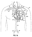
図1Aは、血液循環支援システム10の概略的な多くの可能な構成の1つを示している。本明細書の教示に従って構成された装置およびシステムは、これだけに限定されないが、本明細書で概略的に論じるものを含む任意の適切な外科的方法で植え込むことができ、また例えば、腎臓の内室(図示せず)などの他の生体組織に関連して、または腔または室がそれを通してアクセスされ、液が抜かれるさらに他の生体組織に関連して使用することができる。
FIG. 1A shows one of the many possible configurations of the blood
システム10は、患者22の心臓20の酸素化血液を含む心腔(すなわち、左心房24、または左心室26の左側)から患者の動脈系に血液をポンプ送りするために使用することができ、それにより、疾患または遺伝的な欠陥に起因して弱くなっている心臓20の「負荷を軽減する(unloading)」。システム10は、入口30および出口32を有する血液ポンプ28を含む。ポンプ28は、患者22の左側または右側に植え込むことができるが(左側への植込みが図示されている)、あるいは患者の体の外部に存在することもできる。ポンプ28は、ポンプ28から腹部の位置へと経皮的に伸びる電源コード34を含むことができ、電源コード34は、そこから患者22の外に出て電源(図示せず)に接続される。2001年1月23日にRau他に発行された「Intravascular Blood Pump」と題する特許文献1、2000年9月12日にRau他に発行された「Blood Pump」と題する特許文献2、2005年9月13日にSiessに発行された「Paracardiac Blood Pump」と題する特許文献3、2003年9月23日にSiessに発行された「Blood Pump Without Bearing」と題する特許文献4、および2005年10月6日に公開された「Pump」と題する特許文献5に記載された従来の設計を含む様々な血液ポンプ設計が知られており、かつ使用することができ、その開示を全体的に参照により本明細書に組み込む。
The
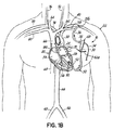
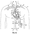
システム10は、心臓20の上方にある、図1Aで示された動脈アクセス部位39aで、大動脈38などの動脈にポンプ28の出口32を接続する流出カニューレ36をさらに含む。代替的には、流出カニューレ36は、図1Bで示すように、左鎖骨下動脈40に位置する動脈アクセス部位39bに接続することもできる。図1Aおよび1Bで示す構成では、ポンプ28は、ポンプポケット42a内に表在的に植え込むことができる。他の代替形態として、また図1Cで示すように、流出カニューレ36は、下行大動脈44に、かつ左および右の腸骨動脈46、48に近接した動脈アクセス部位39cに接続することができる。この場合では、ポンプ28を、患者22の腹部に位置するポンプポケット42bに表在的に植え込むことができる。流出カニューレ36は、適切な移植片(図示せず)、および/または縫合(図示せず)の使用を含むことのできる適切な外科的手技により、選択された動脈に接続することができる。
The
図1Aを再度参照すると、流入カニューレ50は、左心室26の壁52など、心臓20の外壁にポンプ28の入口30を接続する。流入カニューレ50は、この後で論ずる手法の1つなど、任意の望ましい外科的手法により、心臓20の中に送ることができる。
Referring again to FIG. 1A, the
ポンプ28を植え込む前、または後に、流出カニューレ36および流入カニューレ50を、血液ポンプ28の出口32および入口30にそれぞれ接続することができる。この点に関して、カニューレ36、50は、まず、適切に消毒した切断ツール(図示せず)により適切な長さに切ることができ、したがって、システム10は、カニューレ36、50をねじれさせることなく、より容易に植え込むことができる。流入カニューレ50は、後で論ずるように、所望の長さへと容易に切断できるように構成することができる。
Before or after implanting
動作では、血液を、左心室26から、流入カニューレ50を介してポンプ28に送ることができ、またポンプ28から選択された動脈(図1Aの大動脈38、図1Bの左鎖骨下動脈40、図1Cの下行大動脈44、または所望に応じて他のもの)に送ることができる。
In operation, blood can be sent from the left ventricle 26 to the
例示および参照目的のために、心臓20の右側に、右心房54および右心室56を含む特定のさらなる解剖学的構造が示されている。右心房54は、血液を、概して、静脈網から、より具体的には、図示のように、左および右鎖骨下静脈58、60、左および右頸静脈62、64、ならびに上行および下行大静脈66、68から受け取る。血液は、右心房54から右心室56へと進み、次いで、肺(図示せず)にポンプ送りされて酸素化される。肺から戻った血液は、肺静脈70を通り心臓20の左心房24に入る。左心房24内の血液は、左心室26に進み、大動脈38へとポンプ送りされて、左鎖骨下動脈40と、左頸動脈72と、右頸動脈76および右鎖骨下動脈78へと導く腕頭動脈74とを含む動脈系の先へと送られる。
For purposes of illustration and reference, certain additional anatomical structures, including the
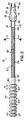
図2を次に参照し、かつ図1Aも引き続き参照すると、流入カニューレ50がより詳細に示されている。流入カニューレ50は、左心室26の壁52など、生体組織を通して挿入されるように構成された先端部110を含む。先端部110は、近位端部分114と遠位端部分116の間で延びる管腔112を含む。流入カニューレ50はまた、近位端部分124と遠位端部分126の間で延びる管腔122を有するシャフト120を含む。流入カニューレ50は、近位端部分134と遠位端部分136の間で延びる管腔132を有するハブ130をさらに含む。シャフト120の遠位端部分126は、先端部110の近位端部分114に結合され、またシャフト120の近位端部分124は、ハブ130の遠位端部分136に結合される。ハブ130は、シャフト120の近位端部分124に直接成形することができるが、代替的に、ハブ130を、別個に構成して、生体適合性のある接着剤を用いて、近位端部分124に取り付けることもできる。管腔112、122、132は、同一直線上にあるように、かつ流体連通するように位置合せされる。管腔112、122、132は、そこに血栓が形成され、流れを制限することを最小化するために、段差もしくは他の不連続性をなくすように同じ直径を有することができる。
Referring now to FIG. 2, and continuing reference to FIG. 1A, the
ハブ130の近位端部分134は、図1Aで示すように、血液ポンプ28の入口30に結合されるように構成することができ、したがって、血液は、心臓20の左心室26から、管腔112、122、132を通り、血液ポンプ28の入口30へと流れることができる。血液は、次いで、流出カニューレ36を通り、図1A、1B、および1Cに関して前に述べたように、大動脈38、下行大動脈44、または左鎖骨下動脈40など、所望の動脈へとポンプ送りすることができる。
The
先端部110は、チタン、チタン合金、ステンレス鋼、または白金などの金属材料から構成することができる。先端部110は、金属材料から構成されたとき、焼結されたセクション、または組織の内部成長を促進する繊維により覆われた少なくとも一部分を含むことができる。代替的には、先端部110は、シリコーンなどの熱硬化性材料から、またはポリウレタンなどの熱可塑性材料から成形することができる。使用できるポリウレタンの例は、CARBOTHANE(Lubrizol Advanced Materials, Inc.、米国オハイオ州クリーブランド)である。比較的、快適な設計が望ましい場合、先端部110は、ショア硬さ約25Aからショア硬さ約90Aの範囲のデュロメータ硬度を有する熱硬化性または熱可塑性材料から構成することができる。比較的剛性のある設計が望ましい場合は、先端部110は、ショア硬さ約55Dからショア硬さ約90Dの範囲のデュロメータ硬度を有する熱硬化性または熱可塑性材料から構成することができる。
The
血栓が形成される可能性をさらに小さくするために、成形工程は、分割線、すなわち、材料のずれが生ずる可能性のある場所をなくすインサート成形工程を含むことができる。インサート成形工程を使用することにより、滑らかで継ぎ目のない、先端部110を通って流れる血液と直接接触する管腔表面が得られる。したがって、抗血栓性材料を用いて管腔112の内側表面を被覆する必要はないが、そうすることが望ましい場合、被覆を含めることもできる。
In order to further reduce the possibility of thrombus formation, the molding process can include an insert molding process that eliminates parting lines, i.e., locations where material misalignment can occur. By using an insert molding process, a luminal surface is obtained that is in direct contact with blood flowing through the
血液適合性を高めるために、先端部110の遠位端部分116は、機械加工工程から生じた凹凸を最小にするために研磨することができる。十分に研磨した表面は、組織の成長が広がるのを最小化し、したがって、組織が先端部110上で成長し、流入カニューレ50内への血流を妨げる可能性を最小化する。
To enhance blood compatibility, the
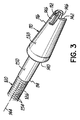
なお図2を、さらに図3を次に参照すると、先端部110のさらなる細部を見ることができる。先端部110の遠位端部分116は、患者の心臓20(図1A)の心腔内に挿入されるように構成される。その点に関して、管腔112の直径は、先端部110の近位端部分114と遠位端部分116の長さを通して全体に一定にすることができるが、先端部110の外側表面138は不連続にすることができる。このような不連続性の1つである肩部140を、近位端部分114と遠位端部分116の間に配置することができ、また遠位端部分116が、例えば、左心室26(図1A)内に挿入されたとき、心臓20(図1A)の壁52(図1A)の内側表面に対して配置されるように構成される。こうすることにより、心腔内に挿入される遠位端部分116の長さを制御し、遠位端部分116が、先端部110を心臓20(図1A)の壁52(図1A)に縫合する前に心腔からはずれないようにする。
Still referring to FIG. 2 and with further reference to FIG. 3, further details of the
外側表面138は、肩部140と遠位端部分116の間で、遠位先端端部142に向けて、切頭円錐形など、先細りさせる、またはテーパを付けることができる。遠位先端端部142は、図示のように、先端部110の長手方向中心軸144に対して実質的に直交するように構成、または成形されうる。この構成は、血液を左心室26(図1A)から連続的に引き抜くことを可能にするが、後で論ずる代替の先端部を含む様々な代替構造が可能である。
The
先端部110は、先端部110の遠位先端端部142が、隣接する内部の心臓組織などにより塞がれる、または妨げられた場合であっても、血液が先端部110の管腔112中に連続的に抜かれることを可能にするように構成された、遠位先端端部142に対して近位方向に延びる開口部146をさらに含む。開口部146は、管腔112と流体連通する、ここでは2つの切込み146で示された様々な形状を含むことができる。円周方向に離間された(180°反対に示された)2つの切込み146は、遠位先端端部142から長手方向に、かつ近位方向に延び、また先端部110の管腔112と外側表面138の間で半径方向に延びる。図2および3の特定の例示的な実施形態は、2つの切込み146を含むが、様々な形状または寸法の任意の数の開口部146、または窓孔を使用できることが理解されよう。切込み146の寸法および数は、すべての切込み146の加算した合計の横断面積が、管腔112の最小の横断面積とほぼ同じであるか、それを超えるように選択することができる。この構成は、遠位先端端部142が、ポンプの動作中に塞がれる、または妨げられた場合であっても、血液の流れの低下を回避する。このような詰まりが生ずるかどうかは、先端部110がそれを通って延びる生体組織の内側表面に対する遠位先端端部142の近さと、流入カニューレ50内に血液がポンプ送りされるときの心腔内の最小の静水圧とによる。より具体的には、ポンプの動作中に心腔の静水圧が低下することにより、心腔が十分に収縮して生体組織が先端部110に接触し、遠位先端端部142を少なくとも部分的に塞ぐ可能性がある。本発明を有する実施形態に従って構成された先端部でこのような詰まりが生じた場合、切込み146を介して血液が管腔112に流入することにより、ポンプ28の連続した動作を進めることができる。したがって、流入カニューレ50中への血液の流れの望ましくない中断を回避することができる。
The
近位端部分114の外側表面150は、研磨され、焼結され、または先端部110が生体組織中に挿入されたとき、外側表面150と接触する生体組織の傷の治癒を促進する、または加速する材料で被覆することができる。適切な材料は、これだけに限らないが、リン酸カルシウム、およびコラーゲンを含むことができる。血液に曝される先端部110の外側表面138の部分は、血栓の形成を最小化するための抗血栓性被覆を含むことができる。使用できる抗血栓性の被覆材料の例は、これだけに限らないが、ヘパリンおよび銀を含む。
The
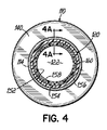
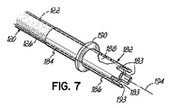
図2〜4を次に参照すると、シャフト120は、熱接合、成形工程により、または接合される部分に十分な温度および圧力を加えるなど他の手段により、先端部110とハブ130に固定することができる。シャフト120は、先端部110およびハブ130を熱的に接合させた一体化構造として構成することができる。代替的には、シャフト120は、複合構造を有することができ、その一例が図4の横断面で示されている。例示的な実施形態では、シャフト120は、内側ライナ152、内側ライナ152に固定された補強構造154、および補強構造154と内側ライナ152の両方に固定された外側被覆156を含むことができる。したがって、図4Aで示すように、内側ライナ152は管状のものであり、シャフト120の管腔122を画定することができる。内側ライナ152は、内側部分158、および外側部分160を有する同時押出しされたライナとすることができ、それは組み合わされて内側ライナ152の壁厚(tsumで示される)を画定する。管腔122の直径に相当する内側部分158の内径は、個々の用途に対する望ましい血液の流量に応じて変わる可能性がある。概して、管腔122は、ハブ130の管腔132、および先端部110の管腔112と同じ直径を有することになる。例えば、管腔122の直径は、約0.040インチ(1.016mm)から約0.400インチ(10.016mm)まで変化することができる。シャフト120の全体の壁厚は、シャフト120の望ましい機械的性能特性(曲げ、コラム(column)強さ、ねじり強さなど)に応じて変わる可能性がある。例えば、シャフト120の壁厚は、約0.004インチ(0.1016mm)から約0.080インチ(2.032mm)まで変わる可能性がある。
Referring now to FIGS. 2-4, the
内側ライナ152の内側部分158は、例えば、ショア硬さ約55Dからショア硬さ約80Dの範囲の比較的高いデュロメータ硬度を有し、かつ約0.0005インチ(0.0127mm)から約0.0050インチ(1.27mm)にわたることのできる厚さt1を有する熱硬化性材料、または熱可塑性材料から構成することができる。適切な熱硬化性材料は、これだけに限らないが、エッチングさせたフッ素重合体、およびポリイミドを含むことができる。適切な熱可塑性材料の例は、これだけに限らないが、ポリアミド、ポリウレタン、およびポリエチレンを含む。使用できるポリウレタンの例はCARBOTHANEである。
The
内側ライナ152の外側部分160は、例えば、ショア硬さ約25Aからショア硬さ約60Aの範囲の低いデュロメータ硬度を有し、かつ約0.0005インチ(0.0127mm)から約0.0100インチ(0.254mm)にわたる厚さt2を有する熱可塑性材料から構成することができる。使用できる適切な材料の例はCARBOTHANE(登録商標)などのポリウレタンである。
The
補強構造154は、内側ライナ152の外側部分160上に重ねることができ、また図3で示すように編組みされた構成を、または図2で示すようにコイル状に巻いた構成を有することができる。補強構造154は、ステンレス鋼またはチタンワイヤなどの金属ワイヤから構成することができるが、KEVLAR(E.I. du Pont de Nemours and Co.、米国デラウェア州ウィルミントン)などのポリマー材料から製作することもできる。さらに、構成材料は、これだけに限らないが、円形、または長方形を含む様々な横断面形状を有することができる。円形のワイヤが使用される場合、ワイヤの直径は、通常、約0.001インチ(0.0254mm)から約0.005インチ(0.127mm)まで変化することができる。長方形の横断面を有する材料が使用される場合、長方形は、通常、約0.001インチ(0.0254mm)から約0.005インチ(0.127mm)の範囲の高さを有し、かつ約0.003インチ(0.0762mm)から約0.010インチ(0.254mm)の範囲の幅を有することができる。
The reinforcing
図2のコイル状に巻かれた構成は、使用される個々のワイヤ、および管腔122の直径に応じて、約0.001インチ(0.0254mm)から約0.060インチ(1.524mm)の範囲のコイルピッチを含むことができる。いくつかの実施形態では、コイルピッチを、シャフト120の長さに沿って変えることができ、より高いコイルピッチが遠位方向に配置されると遠位方向に可撓性が増加する。図3で示す編組み構成では、編組みピック(pic)率(すなわち、編組みの1インチ当たりの交点数)は、約10ppiから約100ppiの範囲とすることができる。いくつかの実施形態では、ピック率を、シャフト120の長さに沿って変えることができ、より高いピック率を遠位方向に配置すると、やはり可撓性が増加する。
The coiled configuration of FIG. 2 provides coil pitches ranging from about 0.001 inch (0.0254 mm) to about 0.060 inch (1.524 mm), depending on the individual wire used and the diameter of
外側被覆156を内側ライナ152と補強構造154の上に載せて、複合構成を完了する。外側被覆156は、ショア硬さ約25Aからショア硬さ約60Aの範囲のデュロメータ硬度を有するポリウレタンなどの熱可塑性材料から構成することができる。外側被覆156の材料は、内側ライナ152の外側部分160の材料、および補強構造154の材料と適合性があるように選択される。この適合性への配慮は、補強構造154の完全なカプセル化を保証し、かつ層間はく離を阻止する、外側被覆156と内側ライナ152の間の完全なポリマー結合を保証する。
An
いくつかの実施形態では、内側部分158、および外側部分160は、同様の、または同じ材料から構成することもできるが、必ずしもそうする必要はない。
In some embodiments, the
具体的に示されていないが、シャフト120は、先端部110をシャフト120に組み立てることを支援する逆とげ、および/またはカニューレ停止部を含むことができる。逆とげは、シャフト120と先端部110の間で締まり嵌めを提供し、停止部は、シャフト120が先端部110に完全に挿入されることを保証する。
Although not specifically shown, the
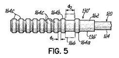
さらに図2を参照すると、ハブ130の例示的な一実施形態が示され、かつ近位端部分134から遠位端部分136へと延びる内側の円筒形部分162を含む。ハブ130は、円筒形部分162と一体化され、その周囲で延びる複数の長手方向に離間された環状部材164をさらに含むことができる。環状部材164は、ハブ130のねじれ半径を制御し、医師がハブ130の長さを切りつめて、患者22の個々の解剖学的構造に適応させることを可能にする。ねじれ半径は、シャフト120の局所的な変形、またはねじれとなりうるシャフト120の曲げ半径であると考えることができる。図2では、環状部材164が、所定の距離d1だけ等しく間隔を空けている。医師は、ハブ130の望ましい長さが提供されるように、隣接する環状部材164の間で円形部分162を切断することにより、ハブ130を必要な長さに切りつめることができる。ハブ130の遠位端部分136は、ハブ130の遠位端部分136をシャフト120の近位端部分124へと容易に接合するために、環状部材164を欠くこともできる。
Still referring to FIG. 2, an exemplary embodiment of the
図5は、上記で規定したd1を超える距離d2をだけ隣接する環状部材164bから長手方向に離間された最も遠位の環状部材164aを含むハブ130'の代替の実施形態を示している。d2の寸法は、想像線で示された流れセンサ166を収容するように選択することができ、流れセンサ166は、流入カニューレ50を通る血液流量を測定するために使用することができる。流れセンサ166は、Transonic Systems, Inc.(米国ニューヨーク州イサカ)から市販の、ハブ130を囲む、超音波技術により動作する流量計など、任意の市販の製品とすることができる。流れセンサ166は、ハブ130にクリップ留めする、またはその他の形で固定することができる。流れセンサ166に関連するワイヤまたはケーブルは、ポンプ28(図1)に関連する電源コード34(図1A)と共に経路を決めることができる。
Figure 5 shows an alternative embodiment of a hub 130 'which includes the most distal ring member 164a of the annular member 164b which is adjacent only the distance d 2 of more than d 1 as defined above spaced longitudinally . The d 2 dimension can be selected to accommodate the flow sensor 166 shown in phantom, and the flow sensor 166 can be used to measure blood flow through the
ハブ130の構成材料は、例えば、シリコーンなどの熱硬化性材料、またはポリウレタンなどの熱可塑性材料など、知られた材料から選択することができる。選択された材料は、ショア硬さ約25Aからショア硬さ約75Aまで変化するデュロメータ硬度を有することができ、またシャフト120の複合構造の全体剛性と概して等しい、またはそれを超える剛性を有することができる。ハブ130は、次いで、シャフト120の近位端部分124に成形される、または接合されうる。
The constituent material of the
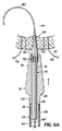
流入カニューレ50を心臓20に接続するための例示的な一手技が、図6A〜6Dで示されているが、図1Aに対してもさらに参照を行う。方法は、図2からの先端部110を含むが、本明細書で示されるものを含む任意の設計を組み込めることが理解されよう。
An exemplary procedure for connecting the
図6Aでは、医師は、外科的部位169でガイドワイヤ168を用いて壁52に穴を開ける。ガイドワイヤ168を受け入れるように構成された管腔175を有するシャフト174に固定された先端部172を含む拡張装置170が、ガイドワイヤ168の上に後方から取り付けられ、心臓20の壁52へと送られる。流入カニューレ50は、拡張装置170の上に後方から取り付けられて、心臓20の壁52へと前進する。
In FIG. 6A, the
図6Aで示すように、ガイドワイヤ168の遠位部分は、少なくとも部分的にループに、コイル状に、またはj形状にすることができ、挿入中および挿入後に、心臓20の組織に外傷を与えないようにする。
As shown in FIG. 6A, the distal portion of the
拡張装置170の先端部172は、概して、ガイドワイヤ168により作成された壁52の穴部を徐々に拡張するように使用できる円錐形状を含む。この徐々に拡張することは、壁52を通る先端部110の挿入を容易にする。挿入は、先端部110の遠位端部分116の切頭円錐形状によってさらに容易になる。
The
図6Bは、先端部110の全体の遠位端部分116が左心室26内に挿入される次の段階を示している。挿入後、先端部110の肩部140が壁52の内側表面に対して配置されるように、流入カニューレ50をわずかに後退させることができ、安定した停止部として働き、かつ医師に知覚可能なフィードバックを提供する。
FIG. 6B shows the next stage where the entire
先端部110がそのように配置されると、巾着縫合糸176、178を使用して、図6Cで示すように結紮し、流入カニューレ50を壁52に完全に固定することができる。必要に応じて、さらなる巾着縫合糸(図示せず)を用いて、さらなる組織を集めることもできるが、これは具体的に示していない。前に論じたように、壁52の穴部を横断して延びる先端部110の近位端部分114の外側表面150は、外側表面150と接触する血管組織の傷の治癒を促進する、または加速する材料を用いて被覆することができる。これは、洩れ防止シールを行うのをさらに支援することができる。
Once the
図6Dは、縫合糸176、178が締め付けられ、かつガイドワイヤ168を備える拡張装置170が、左心室26から後退した後の外科的部位169を示している。その結果、先端部110の遠位端部分116は、左心室26内に挿入されたまま留まり、かつ心臓20の壁52に固定されている。
FIG. 6D shows the
図6A〜6Dで示す手技は、先端部110を挿入するための1つの例示的な外科手術ベースの手技に過ぎないことが容易に理解されよう。代替的には、手技は、先端部110が、心房内中隔180の近傍にある後内側の壁上の位置に、すなわち、いわゆる「Watersonの溝(Waterson's Groove)」に固定されるように左心房24にアクセスするための側方開胸手術、胸部内位置(例えば、Watersonの溝)にアクセスするために、管状のトロカールが使用される胸腔鏡下手術、または針が心房内中隔180を横切るオーバザワイヤ(Seldinger)技法を含むことができ、ガイドワイヤをそこを通して配置することができ、また特殊な導入オブチュレータ(obturator)(または拡張装置)を使用して、流入カニューレ50を心房内中隔180内に前進させることができるが、それを以下でさらに詳細に述べる。
It will be readily appreciated that the procedure shown in FIGS. 6A-6D is only one exemplary surgical base procedure for inserting the
遠位先端端部に対して近位方向に延びる開口部は、図2〜3で示された実施形態を超える任意の数の代替構成を含むように構成できることが、当業者であれば容易に理解されよう。例えば、図7は、図2〜3の先端部110と同様に、部分的に、または完全に詰まった、または妨害された場合であっても、血液の連続的な流れを可能にするように構成された少なくとも1つの開口部183を含む先端部182を示している。その点に関して、先端部182は、管腔188がその間で延びている、近位端部分184と遠位端部分186を含み、図3の先端部110と同様に構成され、かつ製作することができる。近位端部分184、および遠位端部分186は、環状の部材、すなわち座環(seating ring)190により分離することができ、それは、図3で示した先端部110の肩部140と同様の方法で、すなわち、挿入中に、明確な停止部として動作するように構成される。近位端部分184は、前に述べたようにシャフト120の遠位端部分126に固定され、したがって、先端部182の管腔188は、シャフト120の管腔122と流体連通する。
Those skilled in the art will readily appreciate that the opening extending proximally relative to the distal tip end can be configured to include any number of alternative configurations beyond the embodiment shown in FIGS. It will be understood. For example, FIG. 7 is similar to the
少なくとも1つの開口部183は、複数の切込みにより画定される、すなわち、開口部183は、遠位先端端部193から近位方向に延びており、実際に、遠位先端端部193と同一の広がりを有する。したがって、遠位先端端部193は、長手方向中心軸194に対して実質的に直角になるように構成することができる。例示の実施形態では、切込み183は、円周方向に等しく間隔が空けられているが、この間隔構成は必ずしも必要なものではない。さらに、4つの切込み183が示されているが、切込み183の数は、2(図3で示す)から8まで変化することができ、また管腔188の横断面積、切込み183の長さ、および/または切込み183の幅に依存するはずであることが理解されよう。別の言い方をすると、切込み183の数および構成は、血流が制限されるのを回避するために、すべての切込み183の流れ断面積の合計が、管腔188の横断面積とほぼ同じとなるように選択することができる。
At least one
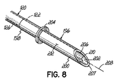
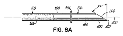
図8および8Aは、管腔202がその間で延びる、近位端部分198と遠位端部分200を含む先端部196のさらに他の実施形態を示す。前に述べたように、近位端部分198は、シャフト120の遠位端部分126に固定され、したがって、先端部196の管腔202がシャフト120の管腔122と流体連通する。さらに、また図7の先端部182と同様に、先端部196は、近位端部分198、および遠位端部分200を分離する座環204を含むことができ、かつ組織の壁52(図1A)の内側表面に対して配置されるように構成される。
8 and 8A illustrate yet another embodiment of a
例示的な実施形態では、先端部196における開口部206は、先端部196の遠位先端端部207から近位方向に延びる傾斜した縁部により画定される。傾斜度は、先端部196の長手方向中心線軸208に対して、約15°から約75°まで変化する角度αとすることができる。
In the exemplary embodiment, the
遠位端部分200は、先端部196を含む材料により囲まれた、また先端部196の管腔202と外側表面の間で延びる窓孔210として本明細書に示された、遠位先端端部207に対して近位方向に延びる第2の開口部210を含む。1つの窓孔210だけが示されているが、遠位端部分200が代替的に複数の窓孔を含みうることが理解されよう。
The
通常のポンプ動作中に、傾斜した縁部206が詰まった状態になる可能性は大幅に低減されている。この方法では、近位方向に延びる開口部206が、血流が確実に管腔202の中に入るのを助けることになる。しかし、傾斜した開口部206を通る血流が減少した場合、血流は、第2の開口部209、窓孔210を通り続けることができる。このように、先端部196は、血流の減少を阻止する2つの方法を提供する。
During normal pump operation, the possibility of the chamfered
さらに他の実施形態では、先端部は、巾着縫合糸に対する必要性を低減する方法で構成することができる。さらに、かつ/または任意選択で、先端部は、特許文献7として公開された、「Transseptal Cannula, Tip, Delivery System, and Method」と題する特許文献6に記載されたものなど、侵襲性の少ない、カテーテルベースの外科的手技で使用するのを容易にするように構成することができ、その開示を全体的に参照により本明細書に組み込む。 In still other embodiments, the tip can be configured in a manner that reduces the need for a purse string suture. In addition, and / or optionally, the tip is less invasive, such as that described in US Pat. No. 6,069,097, entitled “Transseptal Cannula, Tip, Delivery System, and Method” published as US Pat. It can be configured to facilitate use in catheter-based surgical procedures, the disclosure of which is incorporated herein by reference in its entirety.
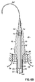
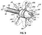
適切な先端部設計の例示的な一実施形態が図9で示されており、それは、図3を参照して前に述べた形状と同様の切頭円錐形を有する先端部250を含む。先端部250は、近位端252および遠位端254を有し、シャフト120の管腔122(図2)と同一直線上にある管腔256がその間で延びている。遠位端254は、2つの切込みとして図9で画定された少なくとも1つの開口部258を含み、それは、遠位先端端部260から近位方向に延びている。
One exemplary embodiment of a suitable tip design is shown in FIG. 9, which includes a
なお図9を参照し、さらに図9Aを次に参照すると、先端部250は、特許文献9として公開された、「Transseptal Cannula Device, Coaxial Balloon Delivery Device, and Methods of Using the Same」と題する特許文献8に記載された複数のストラット264を有する第1のアンカー262をさらに含み、その開示を全体的に参照により本明細書に組み込む。4つのストラット264が示されているが、この数は、そのように限定されるものではなく、アンカーには、個々の医師の必要性または好みに応じて、より少ない、またはさらに多くのストラットが必要となり、または望ましいことが想定されうることも理解されたい。しかし、少なくとも3つのストラット264を設けることにより、植え込まれた先端部250のさらに大きな安定性を得ることができる。
In addition, referring to FIG. 9 and further referring to FIG. 9A, the
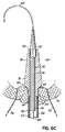
第1のアンカー262のストラット264は、平坦なシート材から部品を化学的にエッチングし、形成工程中に生成された粗い縁部を除去するためにエッチングされた部品を電解研磨し、次いで、部品を加熱して超弾性状態にすることにより、超弾性NiTi材料から少なくとも部分的に構成することができる。しかし、他の適切な生体適合性のある、応従性のない(non-compliant)、可撓性のある材料であっても十分である。図示のように、ストラット264は、接着剤、エポキシ樹脂、摩擦嵌め、または他の知られた手段を用いて先端部250内の溝268の中に固定された共通のリング構造266から延びている。その結果、第1のアンカー262のストラット264は、展開された位置で、共通のリング構造266から、かつ長手方向中心軸269に対して半径方向に延びることができる。この展開された位置では、第1のアンカー262は、右心房54と左心房24の間の、ここでは心房内中隔180として示されている生体組織の第1の側に沿って配置されるように構成される。ストラット264の超弾性状態により、ストラット264は、展開された位置(実線で示す)から角度的に離れた方向を向いている折り畳まれた位置(想像線で示す)に曲がることが可能になる。第1のアンカー262の折畳み可能な性質は、先端部250を送達シース(図示せず)中へと事前に装填することを可能にし、手技の侵襲性を低減する。より具体的には、第1のアンカー262のストラット264は、遠位方向に曲げられて、流入カニューレ50が送達シース中に後方から装填される。遠位方向に向けられたストラット264は、したがって、図9Aの想像線で示される展開に向けて配置される。望ましい場合、バルーンカテーテルを、シャフト120および先端部250の管腔を介して送ることもできる。バルーンは、膨張させたとき、先端部250の内径と接触する。先端部250とバルーンの間のこの接触により、医師が、送達シース内で先端部250の位置を操作することを可能にする。先端部250が心房内中隔180内に位置決めされ、第1のアンカー262が展開された後、送達シースを、外科的部位から後退させることができる。代替的には、送達シースは、送達シースを分割して外科的部位から除去するように、はく離できる材料から構成することもできる。
The
図9および9Aをさらに参照すると、先端部250の近位端部分252は、バンド274に結合された複数のストラット272を含む第2のアンカー270を受け入れ、かつ固定するように形成することができる。ストラット272は、バンド274の溝278内に固定された共通のリング構造276から延びるように構成することができる。第2のアンカー270のストラット272は、(以下で述べるように挿入するための)収縮した状態から、広げた状態へと移行するように動作可能であり、上記で述べたように、ワイヤを用いて形成された、または平坦なシート材から形成された管状構造から機械加工することができる。ワイヤまたは平坦なシート材は、任意の形状記憶材料(ニッケルチタン、NiTi、またはMP35Nなど)とすることができる。ストラット272に対して多くの形状が可能であるが、示された形状は、ストラット272が広がった状態にあるとき、角度の付いた部分272aおよび接触部分272bを含む。接触部分272bは生体組織に接触することになるが、角度の付いた部分272aは、アンカー270を、広い範囲の解剖学的構造および組織厚さに適合できるようにする。角度の付いた部分272aはまた、先端部250に適正に取り付けられた後、アンカー270の遠位方向移動に抗する力を生成する。
With further reference to FIGS. 9 and 9A, the
バンド274は、先端部250と同様の材料から、かつ同様の方法を用いて構成することができる。図9Aで示すように、バンド274は、先端部250の近位端部分252により受け入れられるような形状および寸法であり、かつ摩擦嵌め、締まり嵌め、磁石、ねじ山、または一般に知られた他の生体内(in vivo)組立て方法により固定される。
Band 274 can be constructed from the same material as
送達を行うために、第2のアンカー270は、複数のストラット272が収縮された状態で、かつ近位方向にその中で存在する切込み244を有する第1の送達シース242上に配置される。切込み244は、第2のアンカー270を経皮的に送達するように全体的に低い外形の組立体となることに寄与する。第1の送達シース242、および第2のアンカー270は、第2の送達シース248内に事前に装填され、ユニットとして、前に挿入された先端部250に向けて経皮的に送られる。バンド274は、十分な遠位方向の力を用いて、機械的な接続により、挿入されている先端部250の近位端部分252に取り付けられる。複数のストラット272は、次いで、心房内中隔180から第2の送達シース248を後退させることにより展開されるが、それは第2の送達シース248からハブカテーテル挿入部(図示せず)中へと近位方向に延びる1つまたは複数の接続部材246を引っ張ることを含むことができる。十分に後退させた後、ストラット272は、展開されて、収縮した状態から心房内中隔180に対して展開された状態になる。次いで、第1および第2の送達シース242、248を共に、先端部250から離れる方向に後退させることができる。
To effect delivery, the
図9でさらに示すように、アンカー262、270の一方または両方のストラット264、272は、多孔質のポリマー構造280を含み、心房内中隔180(図9A)に係合させるために、複数のストラット264、272単独よりも広い表面を提供することができる。多孔質のポリマー構造280はまた、組織の内部成長を可能にし、その場合、心房内中隔180からの生体組織は、多孔質のポリマー構造280内で成長し、かつ埋め込まれて、より大きな構造的安定性、および密封能力を提供することができる。多孔質のポリマー構造280のための適切な材料は、これだけに限らないが、ポリエステル単繊維もしくは多繊維糸、ePTFE単繊維もしくは多繊維糸、またはフッ素化されたポリオレフィン繊維もしくは糸を含むことができ、それらを織り、編組みし、編み、またはフェルト状にして適正な構成にすることができる。多孔質のポリマー構造280は、2次元または3次元のハニカム構造、円形、平坦、または3軸の管状構造を有する織物、編組み、または編み物を含む様々な固有の構成をさらに含むことができる。他の実施形態では、多孔質のポリマー構造280は、管状、円筒形、またはシート形態のePTFE部品から構成することができる。概して、多孔質のポリマー構造280は、2枚のシートの原材料(上記で述べたものなど)から、形状をエッチングまたはレーザ切断することにより構成されることになる。形成されたポリマー構造280は、次いで、形成されたポリマー構造280が、間にストラット264、272を捕捉するように、超音波で共に溶接される。
As further shown in FIG. 9, one or both
図9は、第1のアンカー262のストラット264が、第2のアンカー270のストラット272に対して位置がオフセットするように、アンカー262、270を配置できることをさらに示している。この構成は、特定の負荷に耐える利点を有するが、必ず必要なものと考えるべきではない。
FIG. 9 further illustrates that the
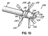
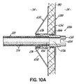
図10および10Aを次に参照すると、先端部286のさらに他の例示的な実施形態が示されている。先端部286は、先端部182(図4)と同様の方法で構成されているが、図9で示すものと同様ではあるが多孔質のポリマー構造280(図9)を含まない第1のアンカー288と、係合可能な第2のアンカー290とを含む。アンカー288、290はそれぞれ、心房内中隔180の対向する側部上に存在するように、複数のストラット292を含む。先端部286は、遠位先端端部298が妨げられる、または塞がれた場合、先端部286の管腔296への流体的なアクセスを提供するために、遠位端298から近位方向に延びる、複数の切込みとして示された少なくとも1つの開口部294をさらに含む。
Referring now to FIGS. 10 and 10A, yet another exemplary embodiment of the
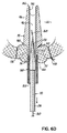
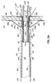
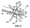
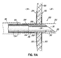
図11および11Aは、第1および第2のアンカー302、304が結合された一体形の中隔内先端部300のさらに他の実施形態を示しており、アンカー302、304は、それぞれ、単一の送達シース318を用いて生体組織に経皮的に送達されうる複数のストラット305を含む。先端部300は、いくつかの理由で設けられた1つまたは複数のリング306を含む。これらのリング306は、アンカー302、304を係合させるように動作し、かつ/またはアンカー302、304を先端部300上に固定するために1つまたは複数のクランプ308と協動して動作することができる。適切なクランプ308は、加圧変形、または圧着式のクランプを含むことができるが、または接着、溶接、または結紮により、先端部300に取り付けることができる。
FIGS. 11 and 11A illustrate yet another embodiment of an
先端部300は、図示のように、例えば、先端部196の遠位先端端部313から近位方向に延びる傾斜した遠位端表面により画定される開口部310、および窓孔の形の開口により画定される開口部312など、2つの開口部310、312を有する図5の先端部196と同様の構造をさらに含む。開口部310、312は、心房内中隔180を通して挿入されたとき、管腔314への詰まり、または流れの制限を生ずる可能性を低減する。先端部300は、シャフト120との摩擦嵌めを提供するための逆とげ316をさらに含む。
The
本発明を、様々な例示的な実施形態を述べることにより示し、かつこれらの諸実施形態をある程度詳細に述べてきているが、このような細部に、添付の特許請求の範囲を制限する、または何らかの形で限定することは出願人の意図するものではない。さらなる利点および変更形態は、当業者であれば容易に明らかとなろう。本発明の様々な特徴は、ユーザの必要性、および好みに応じて、単独で、または任意の組合せで使用することができる。しかし、本発明それ自体は、添付の特許請求の範囲によってのみ定義されるべきである。 While the invention has been illustrated by describing various exemplary embodiments and these embodiments have been described in some detail, such details limit the scope of the appended claims or It is not the applicant's intention to limit in any way. Additional advantages and modifications will be readily apparent to those skilled in the art. The various features of the present invention can be used alone or in any combination depending on the needs and preferences of the user. However, the invention itself should only be defined by the appended claims.
10 血液循環支援システム
20 心臓
22 患者
24 左心房
26 左心室
28 血液ポンプ
30 入口
32 出口
34 電源コード
36 流出カニューレ
38 大動脈
39a 動脈アクセス部位
39b 動脈アクセス部位
39c 動脈アクセス部位
40 左鎖骨下動脈
42a ポンプポケット
42b ポンプポケット
44 下行大動脈
46 左の腸骨動脈
48 右の腸骨動脈
50 流入カニューレ
52 左心室の壁
54 右心房
56 右心室
58 左鎖骨下静脈
60 右鎖骨下静脈
62 左頸静脈
64 右頸静脈
66 上行大静脈
68 下行大静脈
70 肺静脈
72 左頸動脈
74 腕頭動脈
76 右頸動脈
78 右鎖骨下動脈
110 先端部
112 管腔
114 近位端部分
116 遠位端部分
120 シャフト
122 管腔
124 近位端部分
126 遠位端部分
130 ハブ
130' ハブ
132 管腔
134 近位端部分
136 遠位端部分
138 外側表面
140 肩部
142 遠位先端端部
144 長手方向中心軸
146 開口部、切込み
150 外側表面
152 内側ライナ
154 補強構造
156 外側被覆
158 内側部分
160 外側部分
162 円筒形部分
164 環状部材
164a 環状部材
164b 環状部材
166 流れセンサ
168 ガイドワイヤ
169 外科的部位
170 拡張装置
172 先端部
174 シャフト
175 管腔
176 巾着縫合糸
178 巾着縫合糸
180 心房内中隔
182 先端部
183 開口部、切込み
184 近位端部分
186 遠位端部分
188 管腔
190 座環
193 遠位先端端部
194 長手方向中心軸
196 先端部
198 近位端部分
200 遠位端部分
202 管腔
204 座環
206 開口部、縁部
207 遠位先端端部
208 長手方向中心線軸
209 第2の開口部
210 窓孔、第2の開口部
242 第1の送達シース
244 切込み
246 接続部材
248 第2の送達シース
250 先端部
252 近位端、近位端部分
254 遠位端
256 管腔
258 開口部
260 遠位先端端部
262 第1のアンカー
264 ストラット
266 共通のリング構造
268 溝
269 長手方向中心軸
270 第2のアンカー
272 ストラット
272a 角度の付いた部分
272b 接触部分
274 バンド
276 共通のリング構造
278 溝
280 多孔質のポリマー構造
286 先端部
288 第1のアンカー
290 第2のアンカー
292 ストラット
294 開口部
296 管腔
298 遠位先端端部、遠位端
300 先端部
302 第1のアンカー
304 第2のアンカー
305 ストラット
306 リング
308 クランプ
310 開口部
312 開口部
313 遠位先端端部
314 管腔
316 逆とげ
318 送達シース
d1 距離
d2 距離
t1 厚さ
t2 厚さ
tsum 厚さ
α 角度
10 Blood circulation support system
20 heart
22 patients
24 Left atrium
26 Left ventricle
28 Blood pump
30 entrance
32 Exit
34 Power cord
36 Outflow cannula
38 Aorta
39a Arterial access site
39b Arterial access site
39c Arterial access site
40 Left subclavian artery
42a pump pocket
42b pump pocket
44 The descending aorta
46 Left iliac artery
48 Right iliac artery
50 Inflow cannula
52 Left ventricular wall
54 Right Atrium
56 Right ventricle
58 Left subclavian vein
60 Right subclavian vein
62 Left jugular vein
64 Right jugular vein
66 Ascending vena cava
68 descending vena cava
70 Pulmonary vein
72 Left carotid artery
74 brachiocephalic artery
76 Right carotid artery
78 Right subclavian artery
110 Tip
112 lumens
114 Proximal end portion
116 Distal end
120 shaft
122 lumen
124 Proximal end portion
126 Distal end
130 Hub
130 'hub
132 lumens
134 Proximal end portion
136 Distal end
138 outer surface
140 shoulder
142 Distal tip end
144 Longitudinal central axis
146 opening, notch
150 outer surface
152 Inner liner
154 Reinforcement structure
156 outer coating
158 inner part
160 Outer part
162 Cylindrical part
164 Ring member
164a Annular member
164b Annular member
166 Flow sensor
168 Guidewire
169 Surgical site
170 Expansion unit
172 Tip
174 shaft
175 lumen
176 Drawstring suture
178 Drawstring suture
180 Intra-atrial septum
182 Tip
183 opening, notch
184 Proximal end portion
186 Distal end
188 lumen
190 Seat ring
193 Distal tip end
194 Longitudinal central axis
196 Tip
198 Proximal end portion
200 Distal end
202 lumen
204 seat ring
206 Openings, edges
207 Distal tip end
208 Longitudinal centerline axis
209 Second opening
210 Window hole, second opening
242 First delivery sheath
244 depth of cut
246 Connection member
248 Second delivery sheath
250 Tip
252 Proximal end, proximal end part
254 Distal end
256 lumens
258 opening
260 Distal tip end
262 First anchor
264 struts
266 Common ring structure
268 groove
269 Longitudinal central axis
270 Second anchor
272 Strut
272a angled part
272b Contact area
274 bands
276 Common ring structure
278 groove
280 Porous polymer structure
286 Tip
288 First anchor
290 Second anchor
292 Strut
294 opening
296 lumen
298 Distal tip end, distal end
300 Tip
302 First anchor
304 second anchor
305 struts
306 ring
308 Clamp
310 opening
312 opening
313 Distal tip end
314 lumen
316 Reverse thorn
318 Delivery sheath
d 1 distance
d 2 distance
t 1 thickness
t 2 thickness
t sum thickness α angle
Claims (42)
近位端部分、および遠位端部分、ならびにその間で延びる管腔を備えるシャフトと、
近位端部分、遠位先端端部、およびその間で延びる管腔を有する先端部であり、前記先端部の前記近位端部分が、前記シャフトの前記遠位先端端部に固定される先端部とを備え、
前記先端部が、前記管腔と連通し、かつ前記遠位先端端部に対して近位方向に延びる開口部を有しており、近位方向に延びる前記開口部が、前記遠位先端端部が塞がれた場合であっても、液が前記先端部の前記管腔中に連続的に引き込まれることを可能にするように構成され、
前記先端部が、遠位方向に先細りする切頭円錐形を有する外側表面をさらに含み、前記先端部の外側表面は、前記先端部が前記生体組織を通して配置されたとき、前記生体組織の第1の側に当接するように構成された肩部を含み、前記肩部が切頭円錐形部分の近位端と一体的に形成されるカニューレ。 A cannula for insertion through living tissue,
A shaft comprising a proximal end portion and a distal end portion and a lumen extending therebetween;
A tip having a proximal end portion, a distal tip end, and a lumen extending therebetween, wherein the proximal end portion of the tip is secured to the distal tip end of the shaft And
The tip has an opening that communicates with the lumen and extends proximally relative to the distal tip end, wherein the opening extending proximally is the distal tip end. Configured to allow liquid to be continuously drawn into the lumen of the tip, even when the part is blocked ,
The tip further includes an outer surface having a frustoconical shape that tapers in a distal direction, the outer surface of the tip being a first of the living tissue when the tip is disposed through the living tissue. A cannula including a shoulder configured to abut against the side of the frame, wherein the shoulder is integrally formed with the proximal end of the frustoconical portion .
前記カニューレを受け入れるように構成され、かつ前記第1のアンカーを前記拡大した状態に展開するために前記カニューレに対して移動するように構成された送達シースと
を備える送達システム。 The cannula of claim 22 ;
A delivery sheath configured to receive the cannula and configured to move relative to the cannula to deploy the first anchor in the expanded state.
(i)入口および出口を有する血液ポンプと、
(ii)(a)近位端部分および遠位端部分、ならびにその間で延びる管腔を備えるシャフトと、
(b)前記心臓の組織を通して延びるように構成され、近位端部分、遠位先端端部、およびその間で延びる管腔を有する先端部であり、前記先端部の前記管腔が前記シャフトの前記管腔と流体連通するように、前記先端部の前記近位端部分が前記シャフトの前記遠位端部分に固定され、前記先端部が、前記遠位先端端部に対して近位方向に延びる開口部を有し、かつ前記開口部が前記先端部の前記管腔と流体連通する、先端部と
を備える流入カニューレと、
(iii)近位端部分および遠位端部分、ならびにその間で延びる管腔を有する流出カニューレであり、前記近位端部分が、前記動脈に結合されるように構成される、流出カニューレと
を備え、
前記先端部が、遠位方向に先細りする切頭円錐形を有する外側表面をさらに含み、前記先端部の外側表面は、前記先端部が前記生体組織を通して配置されたとき、前記生体組織の第1の側に当接するように構成された肩部を含み、前記肩部が切頭円錐形部分の近位端と一体的に形成される血液循環支援システム。 A blood circulation support system for increasing blood flow between a patient's heart chamber and the patient's artery,
(i) a blood pump having an inlet and an outlet;
(ii) (a) a shaft comprising a proximal end portion and a distal end portion, and a lumen extending therebetween;
(b) a tip configured to extend through the heart tissue and having a proximal end portion, a distal tip end, and a lumen extending therebetween, wherein the lumen of the tip is the portion of the shaft. The proximal end portion of the tip is secured to the distal end portion of the shaft so as to be in fluid communication with a lumen, and the tip extends proximally with respect to the distal tip end. An inflow cannula having an opening, and the opening is in fluid communication with the lumen of the tip;
(iii) an outflow cannula having a proximal end portion and a distal end portion and a lumen extending therebetween, wherein the proximal end portion is configured to be coupled to the artery; ,
The tip further includes an outer surface having a frustoconical shape that tapers in a distal direction, the outer surface of the tip being a first of the living tissue when the tip is disposed through the living tissue. A blood circulation support system comprising a shoulder configured to abut against the side of the head, wherein the shoulder is integrally formed with the proximal end of the frustoconical portion .
Applications Claiming Priority (3)
| Application Number | Priority Date | Filing Date | Title |
|---|---|---|---|
| US30335110P | 2010-02-11 | 2010-02-11 | |
| US61/303,351 | 2010-02-11 | ||
| PCT/US2011/024533 WO2011100552A1 (en) | 2010-02-11 | 2011-02-11 | Devices, methods and systems for establishing supplemental blood flow in the circulatory system |
Publications (2)
| Publication Number | Publication Date |
|---|---|
| JP2013526899A JP2013526899A (en) | 2013-06-27 |
| JP5916632B2 true JP5916632B2 (en) | 2016-05-11 |
Family
ID=44354235
Family Applications (2)
| Application Number | Title | Priority Date | Filing Date |
|---|---|---|---|
| JP2012553035A Expired - Fee Related JP5916632B2 (en) | 2010-02-11 | 2011-02-11 | Apparatus, method and system for establishing supplemental blood flow in the circulatory system |
| JP2012553039A Expired - Fee Related JP5992339B2 (en) | 2010-02-11 | 2011-02-11 | Cannula lined with tissue ingrowth material and method of use thereof |
Family Applications After (1)
| Application Number | Title | Priority Date | Filing Date |
|---|---|---|---|
| JP2012553039A Expired - Fee Related JP5992339B2 (en) | 2010-02-11 | 2011-02-11 | Cannula lined with tissue ingrowth material and method of use thereof |
Country Status (5)
| Country | Link |
|---|---|
| US (3) | US8768487B2 (en) |
| EP (2) | EP2533824B1 (en) |
| JP (2) | JP5916632B2 (en) |
| CA (2) | CA2787632C (en) |
| WO (2) | WO2011100568A1 (en) |
Families Citing this family (47)
| Publication number | Priority date | Publication date | Assignee | Title |
|---|---|---|---|---|
| US7846123B2 (en) | 2007-04-24 | 2010-12-07 | Emory University | Conduit device and system for implanting a conduit device in a tissue wall |
| AU2011217974B2 (en) | 2010-02-17 | 2015-08-20 | Artio Medical, Inc. | System and method to increase the overall diameter of veins |
| CN103228300A (en) | 2010-09-07 | 2013-07-31 | 保罗·A·斯彭斯 | Cannula systems and methods |
| EP2667792B1 (en) | 2011-01-28 | 2020-05-06 | Apica Cardiovascular Limited | Systems for sealing a tissue wall puncture |
| CA2826413A1 (en) | 2011-02-01 | 2012-08-09 | Georgia Tech Research Corporation | Systems for implanting and using a conduit within a tissue wall |
| WO2012174361A1 (en) * | 2011-06-15 | 2012-12-20 | Phraxis Inc. | Arterial venous spool anchor |
| EP3257545A1 (en) | 2011-08-11 | 2017-12-20 | Phase One Medical, LLC | Apparatus for the dialysis of blood |
| US10426878B2 (en) | 2011-08-17 | 2019-10-01 | Flow Forward Medical, Inc. | Centrifugal blood pump systems |
| US10258730B2 (en) | 2012-08-17 | 2019-04-16 | Flow Forward Medical, Inc. | Blood pump systems and methods |
| US9585991B2 (en) * | 2012-10-16 | 2017-03-07 | Heartware, Inc. | Devices, systems, and methods for facilitating flow from the heart to a blood pump |
| WO2014117087A1 (en) | 2013-01-25 | 2014-07-31 | Apica Cardiovascular Limited | Systems and methods for percutaneous access, stabilization and closure of organs |
| CN105188797B (en) * | 2013-03-07 | 2017-09-08 | 塞考利特公司 | Transseptal sleeve pipe, tip, delivery system and method |
| JP6302992B2 (en) | 2013-03-15 | 2018-03-28 | エーピーケー アドバンスド メディカル テクノロジーズ,インコーポレイテッド | Connector for implantation into the tissue wall |
| US10449274B2 (en) | 2013-06-26 | 2019-10-22 | Circulite, Inc. | System and method of facilitating connection between cannulae and a blood pump |
| EP3076884B1 (en) | 2013-12-04 | 2020-02-05 | Heartware, Inc. | Apparatus for cutting an atrial wall |
| US10286190B2 (en) | 2013-12-11 | 2019-05-14 | Cook Medical Technologies Llc | Balloon catheter with dynamic vessel engaging member |
| GB2527075A (en) | 2014-03-17 | 2015-12-16 | Daassist As | Percutaneous system, devices and methods |
| MX2016012135A (en) | 2014-03-17 | 2017-01-19 | Arkis Biosciences | Tunneling guidewire. |
| EP3193761B1 (en) | 2014-09-15 | 2021-03-24 | Novoxel Ltd. | Methods for manufacturing devices for thermal tissue vaporization and compression |
| US10485909B2 (en) | 2014-10-31 | 2019-11-26 | Thoratec Corporation | Apical connectors and instruments for use in a heart wall |
| KR102579711B1 (en) * | 2015-07-20 | 2023-09-15 | 프리스틴 어세스 테크놀로지스 리미티드 | Hemodialysis catheter with corrugated tip |
| US9717830B2 (en) | 2015-10-28 | 2017-08-01 | Circulite, Inc. | Inflow cannula and blood flow assist system |
| WO2017112698A1 (en) | 2015-12-21 | 2017-06-29 | Heartware, Inc. | Axial flow implantable mechanical circulatory support devices with outlet volute |
| US10413647B2 (en) | 2015-12-21 | 2019-09-17 | Heartware, Inc. | Implantable mechanical circulatory support devices |
| US10893847B2 (en) | 2015-12-30 | 2021-01-19 | Nuheart As | Transcatheter insertion system |
| JP2019506202A (en) * | 2016-01-08 | 2019-03-07 | ヌハート エーエスNuheart As | Connector and method for joining anatomical walls |
| US20170196565A1 (en) * | 2016-01-08 | 2017-07-13 | Nuheart As | Method for coupling anatomical walls using a connector |
| US20170197019A1 (en) * | 2016-01-08 | 2017-07-13 | Nuheart As | Connector for fluid communication between two anatomical compartments |
| USD786433S1 (en) | 2016-01-29 | 2017-05-09 | Arkis Biosciences Inc. | Trocar |
| TWI757286B (en) * | 2016-04-29 | 2022-03-11 | 美商亞提歐醫藥公司 | Conduit for transporting blood to a blood pump system and blood pump system |
| US10335528B2 (en) | 2016-10-07 | 2019-07-02 | Nuheart As | Transcatheter method and system for the delivery of intracorporeal devices |
| US10537672B2 (en) | 2016-10-07 | 2020-01-21 | Nuheart As | Transcatheter device and system for the delivery of intracorporeal devices |
| USD835777S1 (en) | 2016-10-27 | 2018-12-11 | Arkis Biosciences Inc. | Guidewire stylette |
| EP3554608A4 (en) * | 2016-12-19 | 2020-09-09 | Medical Components, Inc. | Archflo midline catheter |
| AU2018221018B2 (en) | 2017-02-14 | 2020-09-17 | W. L. Gore & Associates, Inc. | Implantable medical device delivery systems and methods |
| USD822830S1 (en) | 2017-04-20 | 2018-07-10 | Arkis Biosciences Inc. | Catheter retention device |
| US10888646B2 (en) | 2017-04-28 | 2021-01-12 | Nuheart As | Ventricular assist device and method |
| US10537670B2 (en) | 2017-04-28 | 2020-01-21 | Nuheart As | Ventricular assist device and method |
| USD905853S1 (en) | 2018-02-27 | 2020-12-22 | Medical Components, Inc. | Catheter tip |
| US20210220634A1 (en) * | 2018-06-12 | 2021-07-22 | Venstramedical Pty Limited | Intracardiac percutaneous pump for circulatory support and related systems and methods |
| EP3586900A1 (en) * | 2018-06-28 | 2020-01-01 | Medinice S.A. | Cannula for minimally invasive surgical tricuspid valve repair |
| JP7233077B2 (en) * | 2018-09-28 | 2023-03-06 | 国立大学法人東北大学 | blood circulation device |
| CR20220217A (en) * | 2019-11-22 | 2022-09-15 | Edwards Lifesciences Corp | Mechanically expandable shunt implant |
| USD984880S1 (en) | 2020-11-06 | 2023-05-02 | Medical Components, Inc. | Clamp with indicator |
| US20220193392A1 (en) * | 2020-12-23 | 2022-06-23 | Boston Scientific Scimed Inc. | Facilitate Delivery of Devices with High Friction - Braid |
| CN113368326B (en) * | 2021-06-04 | 2022-08-05 | 中国医学科学院阜外医院深圳医院(深圳市孙逸仙心血管医院) | Aorta cannula for external ventricular assist system |
| WO2023059713A2 (en) * | 2021-10-07 | 2023-04-13 | W. L. Gore & Associates, Inc. | Inflow / outflow cannula anchors |
Family Cites Families (113)
| Publication number | Priority date | Publication date | Assignee | Title |
|---|---|---|---|---|
| US3843974A (en) | 1972-01-05 | 1974-10-29 | Us Health Education & Welfare | Intimal lining and pump with vertically drafted webs |
| US3903895A (en) * | 1973-01-05 | 1975-09-09 | Sherwood Medical Ind Inc | Cardiovascular catheter |
| US4033331A (en) * | 1975-07-17 | 1977-07-05 | Guss Stephen B | Cardiac catheter and method of using same |
| US4086665A (en) * | 1976-12-16 | 1978-05-02 | Thermo Electron Corporation | Artificial blood conduit |
| EP0092927B1 (en) * | 1982-04-10 | 1986-08-13 | Nippon Zeon Co., Ltd. | Cannulae |
| JPS6096260A (en) | 1983-10-31 | 1985-05-29 | 日本ゼオン株式会社 | Freely deformable cannula |
| EP0241838B1 (en) | 1986-04-07 | 1992-04-15 | Agency Of Industrial Science And Technology | Antithrombogenic material |
| JPS6346169A (en) * | 1986-04-07 | 1988-02-27 | 工業技術院長 | Antithrombogenic material |
| US4790825A (en) * | 1986-09-05 | 1988-12-13 | Electro Catheter Corporation | Closed chest cannulation method and device for atrial-major artery bypass |
| JPH0295377A (en) * | 1988-09-30 | 1990-04-06 | Nippon Zeon Co Ltd | Resin composition for treatment and production of molding for treatment |
| JPH02156961A (en) * | 1988-12-08 | 1990-06-15 | Toray Ind Inc | Coronary vein cavity catheter |
| US5152782A (en) | 1989-05-26 | 1992-10-06 | Impra, Inc. | Non-porous coated ptfe graft |
| US5190528A (en) * | 1990-10-19 | 1993-03-02 | Boston University | Percutaneous transseptal left atrial cannulation system |
| US5704372A (en) * | 1991-05-29 | 1998-01-06 | Origin Medsystems, Inc. | Endoscopic inflatable retraction devices for separating layers of tissue, and methods of using |
| US5304220A (en) * | 1991-07-03 | 1994-04-19 | Maginot Thomas J | Method and apparatus for implanting a graft prosthesis in the body of a patient |
| US5797960A (en) * | 1993-02-22 | 1998-08-25 | Stevens; John H. | Method and apparatus for thoracoscopic intracardiac procedures |
| JPH06346169A (en) | 1993-06-07 | 1994-12-20 | Komatsu Ltd | Sintered friction material and its production |
| US5443497A (en) * | 1993-11-22 | 1995-08-22 | The Johns Hopkins University | Percutaneous prosthetic by-pass graft and method of use |
| US6102845A (en) * | 1994-02-07 | 2000-08-15 | Baxter International Inc. | Ventricular assist device with minimal blood contacting surfaces |
| US6475232B1 (en) * | 1996-12-10 | 2002-11-05 | Purdue Research Foundation | Stent with reduced thrombogenicity |
| IL111953A (en) * | 1994-12-12 | 2012-04-30 | Medical Influence Technologies Ltd | Device for catheter fixation |
| US6579314B1 (en) * | 1995-03-10 | 2003-06-17 | C.R. Bard, Inc. | Covered stent with encapsulated ends |
| JP3100315B2 (en) * | 1995-07-10 | 2000-10-16 | 信越化学工業株式会社 | Composite tube and method of manufacturing the same |
| US5788626A (en) * | 1995-11-21 | 1998-08-04 | Schneider (Usa) Inc | Method of making a stent-graft covered with expanded polytetrafluoroethylene |
| JP3884501B2 (en) | 1996-03-13 | 2007-02-21 | 宣男 中林 | Artificial blood vessel |
| DE19613564C1 (en) * | 1996-04-04 | 1998-01-08 | Guenter Prof Dr Rau | Intravascular blood pump |
| US5738649A (en) * | 1996-04-16 | 1998-04-14 | Cardeon Corporation | Peripheral entry biventricular catheter system for providing access to the heart for cardiopulmonary surgery or for prolonged circulatory support of the heart |
| US6270477B1 (en) * | 1996-05-20 | 2001-08-07 | Percusurge, Inc. | Catheter for emboli containment |
| US5676670A (en) * | 1996-06-14 | 1997-10-14 | Beth Israel Deaconess Medical Center | Catheter apparatus and method for creating a vascular bypass in-vivo |
| US5928279A (en) * | 1996-07-03 | 1999-07-27 | Baxter International Inc. | Stented, radially expandable, tubular PTFE grafts |
| US5944745A (en) * | 1996-09-25 | 1999-08-31 | Medtronic, Inc. | Implantable medical device capable of prioritizing diagnostic data and allocating memory for same |
| EP0951302B8 (en) * | 1996-10-04 | 2006-04-19 | United States Surgical Corporation | Circulatory support system |
| US6019788A (en) * | 1996-11-08 | 2000-02-01 | Gore Enterprise Holdings, Inc. | Vascular shunt graft and junction for same |
| EP1011458A2 (en) * | 1996-11-08 | 2000-06-28 | Russell A. Houser | Percutaneous bypass graft and securing system |
| US5961545A (en) * | 1997-01-17 | 1999-10-05 | Meadox Medicals, Inc. | EPTFE graft-stent composite device |
| EP0975285B1 (en) * | 1997-04-01 | 2008-10-01 | CAP Biotechnology, Inc. | Calcium phosphate microcarriers and microspheres |
| US6217546B1 (en) * | 1997-05-19 | 2001-04-17 | United States Surgical Corporation | Catheter system |
| US5947940A (en) * | 1997-06-23 | 1999-09-07 | Beisel; Robert F. | Catheter reinforced to prevent luminal collapse and tensile failure thereof |
| US6532964B2 (en) | 1997-07-11 | 2003-03-18 | A-Med Systems, Inc. | Pulmonary and circulatory blood flow support devices and methods for heart surgery procedures |
| US6123725A (en) * | 1997-07-11 | 2000-09-26 | A-Med Systems, Inc. | Single port cardiac support apparatus |
| US5858009A (en) * | 1997-08-14 | 1999-01-12 | Medtronic, Inc. | Multi-lumen cannula |
| US6468300B1 (en) * | 1997-09-23 | 2002-10-22 | Diseno Y Desarrollo Medico, S.A. De C.V. | Stent covered heterologous tissue |
| UA56262C2 (en) * | 1997-10-09 | 2003-05-15 | Орквіс Медікел Корпорейшн | Extracardiac pumping system for supplementing blood circulation |
| US6007478A (en) * | 1997-11-13 | 1999-12-28 | Impella Cardiotechnik Aktiengesellschaft | Cannula having constant wall thickness with increasing distal flexibility and method of making |
| US6540693B2 (en) * | 1998-03-03 | 2003-04-01 | Senorx, Inc. | Methods and apparatus for securing medical instruments to desired locations in a patients body |
| US6186999B1 (en) * | 1998-08-27 | 2001-02-13 | The Cleveland Clinic Foundation | Rigid clampable cannula |
| US6926662B1 (en) * | 1998-12-23 | 2005-08-09 | A-Med Systems, Inc. | Left and right side heart support |
| US6398803B1 (en) * | 1999-02-02 | 2002-06-04 | Impra, Inc., A Subsidiary Of C.R. Bard, Inc. | Partial encapsulation of stents |
| US6558414B2 (en) * | 1999-02-02 | 2003-05-06 | Impra, Inc. | Partial encapsulation of stents using strips and bands |
| US6050975A (en) * | 1999-02-25 | 2000-04-18 | Thermo Cardiosystems, Inc. | Control of tissue growth in textured blood-contacting surfaces |
| US6290639B1 (en) * | 1999-07-16 | 2001-09-18 | Tofy Mussivand | Conduit for a mechanical circulatory device |
| US6383171B1 (en) * | 1999-10-12 | 2002-05-07 | Allan Will | Methods and devices for protecting a passageway in a body when advancing devices through the passageway |
| US6440164B1 (en) * | 1999-10-21 | 2002-08-27 | Scimed Life Systems, Inc. | Implantable prosthetic valve |
| AU784413B2 (en) | 1999-11-11 | 2006-03-30 | Edwards Lifesciences Corporation | Venous return cannula with enhanced drainage |
| US6602263B1 (en) * | 1999-11-30 | 2003-08-05 | St. Jude Medical Atg, Inc. | Medical grafting methods and apparatus |
| US6808533B1 (en) * | 2000-07-28 | 2004-10-26 | Atrium Medical Corporation | Covered stent and method of covering a stent |
| US20020099392A1 (en) * | 2001-01-24 | 2002-07-25 | Mowry David H. | Autoanastomosis device and connection technique |
| US6752829B2 (en) * | 2001-01-30 | 2004-06-22 | Scimed Life Systems, Inc. | Stent with channel(s) for containing and delivering a biologically active material and method for manufacturing the same |
| US6994666B2 (en) * | 2001-06-05 | 2006-02-07 | Edwards Lifesciences Corporation | Non-porous smooth ventricular assist device conduit |
| US7560006B2 (en) * | 2001-06-11 | 2009-07-14 | Boston Scientific Scimed, Inc. | Pressure lamination method for forming composite ePTFE/textile and ePTFE/stent/textile prostheses |
| US6652508B2 (en) | 2001-11-09 | 2003-11-25 | Scimed Life Systems, Inc. | Intravascular microcatheter having hypotube proximal shaft with transition |
| US20030125790A1 (en) * | 2001-12-27 | 2003-07-03 | Vitaly Fastovsky | Deployment device, system and method for medical implantation |
| US6866805B2 (en) * | 2001-12-27 | 2005-03-15 | Advanced Cardiovascular Systems, Inc. | Hybrid intravascular stent |
| US7294124B2 (en) * | 2001-12-28 | 2007-11-13 | Boston Scientific Scimed, Inc. | Hypotube with improved strain relief |
| US6911040B2 (en) * | 2002-01-24 | 2005-06-28 | Cordis Corporation | Covered segmented stent |
| WO2003066118A1 (en) | 2002-02-05 | 2003-08-14 | Thoratec Corporation | Coated vascular prosthesis and methods of manufacture and use. |
| US6946173B2 (en) * | 2002-03-21 | 2005-09-20 | Advanced Cardiovascular Systems, Inc. | Catheter balloon formed of ePTFE and a diene polymer |
| US20030181843A1 (en) * | 2002-06-11 | 2003-09-25 | Scout Medical Technologies, Llc | Device and method providing arterial blood flow for perfusion of ischemic myocardium |
| US6984243B2 (en) * | 2002-07-30 | 2006-01-10 | Cordis Corporation | Abrasion resistant vascular graft |
| US20040122283A1 (en) * | 2002-09-10 | 2004-06-24 | Miwatec Incorporated | Cannula tip for a cardiac assist device |
| US7686758B2 (en) | 2002-09-10 | 2010-03-30 | Hitmac (Usa), Inc. | Cannula tip for a cardiac assist device |
| US7625337B2 (en) * | 2003-01-17 | 2009-12-01 | Gore Enterprise Holdings, Inc. | Catheter assembly |
| JP4505720B2 (en) | 2003-02-10 | 2010-07-21 | 日本電気硝子株式会社 | Molten glass supply apparatus, glass molded article, and method for producing glass molded article |
| US7077801B2 (en) * | 2003-02-19 | 2006-07-18 | Corlife Gbr | Methods and devices for improving cardiac output |
| AU2003901345A0 (en) * | 2003-03-21 | 2003-04-03 | Ventracor Limited | Improved cannula |
| US6965791B1 (en) * | 2003-03-26 | 2005-11-15 | Sorenson Medical, Inc. | Implantable biosensor system, apparatus and method |
| JP2005058304A (en) * | 2003-08-08 | 2005-03-10 | Terumo Corp | Introducer sheath |
| US7762977B2 (en) * | 2003-10-08 | 2010-07-27 | Hemosphere, Inc. | Device and method for vascular access |
| WO2005037345A2 (en) | 2003-10-17 | 2005-04-28 | Vanderbilt University | Percutaneously-inserted ventricular assist devices and related methods |
| JP2005144054A (en) * | 2003-11-19 | 2005-06-09 | Nippon Sherwood Medical Industries Ltd | Cannula |
| US7780692B2 (en) * | 2003-12-05 | 2010-08-24 | Onset Medical Corporation | Expandable percutaneous sheath |
| US9241735B2 (en) * | 2003-12-05 | 2016-01-26 | Onset Medical Corporation | Expandable percutaneous sheath |
| US7585290B2 (en) * | 2004-01-20 | 2009-09-08 | Ethicon Endo-Surgery, Inc. | Medical device for providing access |
| US7699864B2 (en) * | 2004-03-18 | 2010-04-20 | Onset Medical Corporation | Expandable medical access device |
| US7510561B2 (en) * | 2004-03-23 | 2009-03-31 | Correx, Inc. | Apparatus and method for connecting a conduit to a hollow organ |
| US7785318B2 (en) * | 2004-05-27 | 2010-08-31 | Abbott Laboratories | Catheter having plurality of stiffening members |
| WO2006031596A2 (en) * | 2004-09-09 | 2006-03-23 | Onset Medical Corporation | Expandable gastrointestinal sheath |
| WO2006031619A2 (en) * | 2004-09-09 | 2006-03-23 | Onset Medical Corporation | Expandable transluminal sheath |
| US7892203B2 (en) * | 2004-09-09 | 2011-02-22 | Onset Medical Corporation | Expandable transluminal sheath |
| US20060135962A1 (en) * | 2004-09-09 | 2006-06-22 | Kick George F | Expandable trans-septal sheath |
| WO2006068841A2 (en) * | 2004-12-21 | 2006-06-29 | C. R. Bard, Inc. | Hemostasis cuff for catheter securement |
| US20060253102A1 (en) * | 2004-12-21 | 2006-11-09 | Nance Edward J | Non-expandable transluminal access sheath |
| US20080109058A1 (en) * | 2005-06-01 | 2008-05-08 | Cook Incorporated | Intraoperative Anastomosis Method |
| EP1825872A3 (en) * | 2006-02-23 | 2007-10-03 | Levitronix LLC | A pump-inflow-cannula, a pump-outflow-cannula and a blood managing system |
| EP1990066B1 (en) * | 2006-02-23 | 2017-03-08 | Thoratec Delaware LLC | A pump-outflow-cannula and a blood managing system |
| EP1839601A1 (en) | 2006-03-30 | 2007-10-03 | Levitronix LLC | Self-expanding cannula |
| JP2009533157A (en) * | 2006-04-12 | 2009-09-17 | プロテウス バイオメディカル インコーポレイテッド | Embedded sealed structure without voids |
| ITMI20061080A1 (en) | 2006-06-01 | 2007-12-02 | Ngc Medical Spa | EQUIPMENT FOR MYOCARDIC REASCULARIZATION IN HEART WITH HEART AND LEFT VENTRICULAR ASSISTANCE |
| WO2008073852A2 (en) * | 2006-12-08 | 2008-06-19 | Onset Medical Corporation | Expandable medical access sheath |
| US8337518B2 (en) * | 2006-12-20 | 2012-12-25 | Onset Medical Corporation | Expandable trans-septal sheath |
| US7722568B2 (en) * | 2007-01-29 | 2010-05-25 | Onset Medical Corporation | Expandable intra-aortic balloon pump sheath |
| US8900214B2 (en) * | 2007-03-30 | 2014-12-02 | Onset Medical Corporation | Expandable trans-septal sheath |
| WO2008124361A2 (en) * | 2007-04-06 | 2008-10-16 | Cook Biotech Incorporated | Fistula plugs having increased column strength and fistula plug delivery apparatuses and methods |
| JP2008279188A (en) | 2007-05-14 | 2008-11-20 | National Cardiovascular Center | Cannula |
| EP2170449B1 (en) * | 2007-07-19 | 2013-01-16 | CircuLite, Inc. | Cannula for heart chamber implantation and related systems and methods |
| US20090093873A1 (en) * | 2007-09-28 | 2009-04-09 | The Cleveland Clinic Foundation | Vascular graft and method of use |
| US8343029B2 (en) * | 2007-10-24 | 2013-01-01 | Circulite, Inc. | Transseptal cannula, tip, delivery system, and method |
| US20090112049A1 (en) * | 2007-10-29 | 2009-04-30 | Saudi Arabian Oil Company | Heart pump apparatus and method for beating heart surgery |
| CN101983040A (en) * | 2008-02-05 | 2011-03-02 | 丝绸之路医药公司 | Interventional catheter system and methods |
| US9440054B2 (en) * | 2008-05-14 | 2016-09-13 | Onset Medical Corporation | Expandable transapical sheath and method of use |
| JP4996578B2 (en) | 2008-10-28 | 2012-08-08 | 株式会社サンメディカル技術研究所 | Medical device or instrument comprising a porous structure |
| US7951110B2 (en) * | 2008-11-10 | 2011-05-31 | Onset Medical Corporation | Expandable spinal sheath and method of use |
| US20100249491A1 (en) * | 2009-03-27 | 2010-09-30 | Circulite, Inc. | Two-piece transseptal cannula, delivery system, and method of delivery |
-
2011
- 2011-02-11 EP EP11742866.4A patent/EP2533824B1/en not_active Not-in-force
- 2011-02-11 JP JP2012553035A patent/JP5916632B2/en not_active Expired - Fee Related
- 2011-02-11 JP JP2012553039A patent/JP5992339B2/en not_active Expired - Fee Related
- 2011-02-11 WO PCT/US2011/024558 patent/WO2011100568A1/en active Search and Examination
- 2011-02-11 US US13/025,757 patent/US8768487B2/en not_active Expired - Fee Related
- 2011-02-11 EP EP11742879.7A patent/EP2533825B1/en not_active Not-in-force
- 2011-02-11 CA CA2787632A patent/CA2787632C/en not_active Expired - Fee Related
- 2011-02-11 CA CA2788129A patent/CA2788129C/en not_active Expired - Fee Related
- 2011-02-11 US US13/025,845 patent/US9504776B2/en active Active
- 2011-02-11 WO PCT/US2011/024533 patent/WO2011100552A1/en active Application Filing
-
2014
- 2014-05-16 US US14/279,735 patent/US9132216B2/en not_active Expired - Fee Related
Also Published As
| Publication number | Publication date |
|---|---|
| EP2533824A1 (en) | 2012-12-19 |
| WO2011100568A1 (en) | 2011-08-18 |
| US20140249357A1 (en) | 2014-09-04 |
| US20110196191A1 (en) | 2011-08-11 |
| WO2011100552A1 (en) | 2011-08-18 |
| CA2788129A1 (en) | 2011-08-18 |
| US9132216B2 (en) | 2015-09-15 |
| US9504776B2 (en) | 2016-11-29 |
| CA2787632A1 (en) | 2011-08-18 |
| JP2013519450A (en) | 2013-05-30 |
| JP2013526899A (en) | 2013-06-27 |
| US8768487B2 (en) | 2014-07-01 |
| WO2011100552A8 (en) | 2018-08-30 |
| EP2533825A4 (en) | 2017-09-27 |
| EP2533825B1 (en) | 2018-11-14 |
| US20110196190A1 (en) | 2011-08-11 |
| EP2533824B1 (en) | 2019-01-02 |
| CA2788129C (en) | 2016-04-05 |
| EP2533824A4 (en) | 2017-12-20 |
| JP5992339B2 (en) | 2016-09-14 |
| EP2533825A1 (en) | 2012-12-19 |
| CA2787632C (en) | 2017-05-16 |
Similar Documents
| Publication | Publication Date | Title |
|---|---|---|
| JP5916632B2 (en) | Apparatus, method and system for establishing supplemental blood flow in the circulatory system | |
| US9211367B2 (en) | Transseptal cannula, tip, delivery system, and method | |
| JP5733708B2 (en) | Septal cannula and tip and further delivery system and method | |
| EP2233165B1 (en) | Two-piece transseptal cannula and delivery system | |
| AU2014225916B2 (en) | Transseptal cannula, tip, delivery system, and method |
Legal Events
| Date | Code | Title | Description |
|---|---|---|---|
| A621 | Written request for application examination |
Free format text: JAPANESE INTERMEDIATE CODE: A621 Effective date: 20130913 |
|
| A977 | Report on retrieval |
Free format text: JAPANESE INTERMEDIATE CODE: A971007 Effective date: 20140626 |
|
| A131 | Notification of reasons for refusal |
Free format text: JAPANESE INTERMEDIATE CODE: A131 Effective date: 20140714 |
|
| A601 | Written request for extension of time |
Free format text: JAPANESE INTERMEDIATE CODE: A601 Effective date: 20141014 |
|
| A602 | Written permission of extension of time |
Free format text: JAPANESE INTERMEDIATE CODE: A602 Effective date: 20141021 |
|
| A521 | Request for written amendment filed |
Free format text: JAPANESE INTERMEDIATE CODE: A523 Effective date: 20141106 |
|
| A131 | Notification of reasons for refusal |
Free format text: JAPANESE INTERMEDIATE CODE: A131 Effective date: 20150518 |
|
| TRDD | Decision of grant or rejection written | ||
| A01 | Written decision to grant a patent or to grant a registration (utility model) |
Free format text: JAPANESE INTERMEDIATE CODE: A01 Effective date: 20160307 |
|
| A61 | First payment of annual fees (during grant procedure) |
Free format text: JAPANESE INTERMEDIATE CODE: A61 Effective date: 20160405 |
|
| R150 | Certificate of patent or registration of utility model |
Ref document number: 5916632 Country of ref document: JP Free format text: JAPANESE INTERMEDIATE CODE: R150 |
|
| LAPS | Cancellation because of no payment of annual fees |