JP5912032B2 - Temporary enclosure - Google Patents
Temporary enclosure Download PDFInfo
- Publication number
- JP5912032B2 JP5912032B2 JP2011250563A JP2011250563A JP5912032B2 JP 5912032 B2 JP5912032 B2 JP 5912032B2 JP 2011250563 A JP2011250563 A JP 2011250563A JP 2011250563 A JP2011250563 A JP 2011250563A JP 5912032 B2 JP5912032 B2 JP 5912032B2
- Authority
- JP
- Japan
- Prior art keywords
- reagent
- reagent cassette
- cassette
- unit
- station
- Prior art date
- Legal status (The legal status is an assumption and is not a legal conclusion. Google has not performed a legal analysis and makes no representation as to the accuracy of the status listed.)
- Active
Links
- 239000003153 chemical reaction reagent Substances 0.000 claims description 309
- 239000012491 analyte Substances 0.000 claims description 71
- 238000000034 method Methods 0.000 claims description 42
- 239000007788 liquid Substances 0.000 claims description 36
- 238000004458 analytical method Methods 0.000 claims description 23
- 238000001816 cooling Methods 0.000 claims description 22
- 238000012546 transfer Methods 0.000 claims description 9
- 238000012360 testing method Methods 0.000 claims description 7
- 230000007774 longterm Effects 0.000 claims description 6
- 238000012545 processing Methods 0.000 description 72
- 239000000523 sample Substances 0.000 description 52
- 238000003199 nucleic acid amplification method Methods 0.000 description 21
- 230000003321 amplification Effects 0.000 description 20
- 108020004707 nucleic acids Proteins 0.000 description 20
- 102000039446 nucleic acids Human genes 0.000 description 20
- 150000007523 nucleic acids Chemical class 0.000 description 20
- 239000007787 solid Substances 0.000 description 18
- 239000000463 material Substances 0.000 description 16
- 230000032258 transport Effects 0.000 description 16
- 238000006243 chemical reaction Methods 0.000 description 15
- 238000000926 separation method Methods 0.000 description 14
- 230000008901 benefit Effects 0.000 description 7
- 230000027455 binding Effects 0.000 description 7
- 238000001514 detection method Methods 0.000 description 7
- 239000012530 fluid Substances 0.000 description 6
- 230000007723 transport mechanism Effects 0.000 description 5
- 102000004190 Enzymes Human genes 0.000 description 4
- 108090000790 Enzymes Proteins 0.000 description 4
- VYPSYNLAJGMNEJ-UHFFFAOYSA-N Silicium dioxide Chemical compound O=[Si]=O VYPSYNLAJGMNEJ-UHFFFAOYSA-N 0.000 description 3
- 230000002457 bidirectional effect Effects 0.000 description 3
- 230000008569 process Effects 0.000 description 3
- 238000007789 sealing Methods 0.000 description 3
- 239000000725 suspension Substances 0.000 description 3
- 239000011534 wash buffer Substances 0.000 description 3
- 238000005406 washing Methods 0.000 description 3
- 239000002699 waste material Substances 0.000 description 3
- 150000001875 compounds Chemical class 0.000 description 2
- 238000010586 diagram Methods 0.000 description 2
- 238000002955 isolation Methods 0.000 description 2
- 238000005259 measurement Methods 0.000 description 2
- 230000007246 mechanism Effects 0.000 description 2
- 229920000642 polymer Polymers 0.000 description 2
- 238000000746 purification Methods 0.000 description 2
- 230000009467 reduction Effects 0.000 description 2
- 239000000126 substance Substances 0.000 description 2
- 230000001960 triggered effect Effects 0.000 description 2
- 108020004711 Nucleic Acid Probes Proteins 0.000 description 1
- 230000015572 biosynthetic process Effects 0.000 description 1
- 230000003196 chaotropic effect Effects 0.000 description 1
- 239000013522 chelant Substances 0.000 description 1
- 238000004140 cleaning Methods 0.000 description 1
- 239000012459 cleaning agent Substances 0.000 description 1
- 239000003085 diluting agent Substances 0.000 description 1
- 239000000975 dye Substances 0.000 description 1
- 238000003780 insertion Methods 0.000 description 1
- 230000037431 insertion Effects 0.000 description 1
- 238000011901 isothermal amplification Methods 0.000 description 1
- 239000006249 magnetic particle Substances 0.000 description 1
- 238000007885 magnetic separation Methods 0.000 description 1
- 239000002923 metal particle Substances 0.000 description 1
- 239000000203 mixture Substances 0.000 description 1
- 230000009871 nonspecific binding Effects 0.000 description 1
- 239000002853 nucleic acid probe Substances 0.000 description 1
- 238000001921 nucleic acid quantification Methods 0.000 description 1
- 230000000737 periodic effect Effects 0.000 description 1
- 229920001184 polypeptide Polymers 0.000 description 1
- 238000002360 preparation method Methods 0.000 description 1
- 102000004196 processed proteins & peptides Human genes 0.000 description 1
- 108090000765 processed proteins & peptides Proteins 0.000 description 1
- 230000002035 prolonged effect Effects 0.000 description 1
- 102000004169 proteins and genes Human genes 0.000 description 1
- 108090000623 proteins and genes Proteins 0.000 description 1
- 238000011002 quantification Methods 0.000 description 1
- 239000011541 reaction mixture Substances 0.000 description 1
- 238000003753 real-time PCR Methods 0.000 description 1
- 230000000717 retained effect Effects 0.000 description 1
- 238000001179 sorption measurement Methods 0.000 description 1
- 239000013076 target substance Substances 0.000 description 1
Images


Classifications
-
- G—PHYSICS
- G01—MEASURING; TESTING
- G01N—INVESTIGATING OR ANALYSING MATERIALS BY DETERMINING THEIR CHEMICAL OR PHYSICAL PROPERTIES
- G01N35/00—Automatic analysis not limited to methods or materials provided for in any single one of groups G01N1/00 - G01N33/00; Handling materials therefor
- G01N35/02—Automatic analysis not limited to methods or materials provided for in any single one of groups G01N1/00 - G01N33/00; Handling materials therefor using a plurality of sample containers moved by a conveyor system past one or more treatment or analysis stations
- G01N35/026—Automatic analysis not limited to methods or materials provided for in any single one of groups G01N1/00 - G01N33/00; Handling materials therefor using a plurality of sample containers moved by a conveyor system past one or more treatment or analysis stations having blocks or racks of reaction cells or cuvettes
-
- G—PHYSICS
- G01—MEASURING; TESTING
- G01N—INVESTIGATING OR ANALYSING MATERIALS BY DETERMINING THEIR CHEMICAL OR PHYSICAL PROPERTIES
- G01N35/00—Automatic analysis not limited to methods or materials provided for in any single one of groups G01N1/00 - G01N33/00; Handling materials therefor
- G01N35/10—Devices for transferring samples or any liquids to, in, or from, the analysis apparatus, e.g. suction devices, injection devices
- G01N35/1002—Reagent dispensers
-
- G—PHYSICS
- G01—MEASURING; TESTING
- G01N—INVESTIGATING OR ANALYSING MATERIALS BY DETERMINING THEIR CHEMICAL OR PHYSICAL PROPERTIES
- G01N35/00—Automatic analysis not limited to methods or materials provided for in any single one of groups G01N1/00 - G01N33/00; Handling materials therefor
- G01N35/00584—Control arrangements for automatic analysers
- G01N35/00722—Communications; Identification
- G01N35/00732—Identification of carriers, materials or components in automatic analysers
-
- G—PHYSICS
- G01—MEASURING; TESTING
- G01N—INVESTIGATING OR ANALYSING MATERIALS BY DETERMINING THEIR CHEMICAL OR PHYSICAL PROPERTIES
- G01N35/00—Automatic analysis not limited to methods or materials provided for in any single one of groups G01N1/00 - G01N33/00; Handling materials therefor
- G01N35/0099—Automatic analysis not limited to methods or materials provided for in any single one of groups G01N1/00 - G01N33/00; Handling materials therefor comprising robots or similar manipulators
-
- G—PHYSICS
- G01—MEASURING; TESTING
- G01N—INVESTIGATING OR ANALYSING MATERIALS BY DETERMINING THEIR CHEMICAL OR PHYSICAL PROPERTIES
- G01N35/00—Automatic analysis not limited to methods or materials provided for in any single one of groups G01N1/00 - G01N33/00; Handling materials therefor
- G01N2035/00346—Heating or cooling arrangements
- G01N2035/00435—Refrigerated reagent storage
-
- G—PHYSICS
- G01—MEASURING; TESTING
- G01N—INVESTIGATING OR ANALYSING MATERIALS BY DETERMINING THEIR CHEMICAL OR PHYSICAL PROPERTIES
- G01N35/00—Automatic analysis not limited to methods or materials provided for in any single one of groups G01N1/00 - G01N33/00; Handling materials therefor
- G01N35/00584—Control arrangements for automatic analysers
- G01N35/00722—Communications; Identification
- G01N35/00732—Identification of carriers, materials or components in automatic analysers
- G01N2035/00742—Type of codes
- G01N2035/00762—Type of codes magnetic code
-
- G—PHYSICS
- G01—MEASURING; TESTING
- G01N—INVESTIGATING OR ANALYSING MATERIALS BY DETERMINING THEIR CHEMICAL OR PHYSICAL PROPERTIES
- G01N35/00—Automatic analysis not limited to methods or materials provided for in any single one of groups G01N1/00 - G01N33/00; Handling materials therefor
- G01N35/00584—Control arrangements for automatic analysers
- G01N35/00722—Communications; Identification
- G01N35/00732—Identification of carriers, materials or components in automatic analysers
- G01N2035/00821—Identification of carriers, materials or components in automatic analysers nature of coded information
- G01N2035/00851—Identification of carriers, materials or components in automatic analysers nature of coded information process control parameters
-
- G—PHYSICS
- G01—MEASURING; TESTING
- G01N—INVESTIGATING OR ANALYSING MATERIALS BY DETERMINING THEIR CHEMICAL OR PHYSICAL PROPERTIES
- G01N35/00—Automatic analysis not limited to methods or materials provided for in any single one of groups G01N1/00 - G01N33/00; Handling materials therefor
- G01N35/02—Automatic analysis not limited to methods or materials provided for in any single one of groups G01N1/00 - G01N33/00; Handling materials therefor using a plurality of sample containers moved by a conveyor system past one or more treatment or analysis stations
- G01N35/04—Details of the conveyor system
- G01N2035/046—General conveyor features
- G01N2035/0462—Buffers [FIFO] or stacks [LIFO] for holding carriers between operations
Landscapes
- Chemical & Material Sciences (AREA)
- General Health & Medical Sciences (AREA)
- Life Sciences & Earth Sciences (AREA)
- Health & Medical Sciences (AREA)
- Analytical Chemistry (AREA)
- Biochemistry (AREA)
- Physics & Mathematics (AREA)
- General Physics & Mathematics (AREA)
- Immunology (AREA)
- Pathology (AREA)
- Chemical Kinetics & Catalysis (AREA)
- Engineering & Computer Science (AREA)
- Robotics (AREA)
- Automatic Analysis And Handling Materials Therefor (AREA)
Description
本発明は、分析対象物を検出又は定量する自動分析器及び自動システム、並びに、サンプル中の分析対象物を検出又は定量する方法に関する。 The present invention relates to an automatic analyzer and an automatic system for detecting or quantifying an analyte, and a method for detecting or quantifying an analyte in a sample.
一般的に、対象者の状態を診断するために、又は、ひとり以上の対象者からの複数のサンプルの貯蔵物を検査するために、自動分析器が使用される。1つのサンプル中の分析対象物を分析するために、複数種の試薬が必要とされる。斯かる試薬は、上記分析器に対して提供されると共に、該分析器内で配分されねばならない。故に、試薬は一般的に、上記分析器に対して装填又は装填解除され得る試薬カセット内に維持される。 In general, automated analyzers are used to diagnose a subject's condition or to examine a collection of multiple samples from one or more subjects. Multiple types of reagents are required to analyze the analyte in one sample. Such reagents must be provided to the analyzer and distributed within the analyzer. Thus, reagents are generally maintained in a reagent cassette that can be loaded or unloaded from the analyzer.
多くの場合、斯かる試薬は温度に影響されやすい。一定の分析器において、試薬は、単一回の装填に対して装填されるだけであり、その後に手動的に取出されて冷蔵器内へと移送される。また、供与時に冷却して格納を行う分析器も知られている。
本発明は、試薬に対する優れた格納システムに関する。
In many cases, such reagents are sensitive to temperature. In certain analyzers, the reagents are only loaded for a single load, after which they are manually removed and transferred into the refrigerator. Also known are analyzers that cool and store during donation.
The present invention relates to an excellent storage system for reagents.
本発明は、分析対象物を単離及び/又は分析する自動分析器であって、液体を移送するユニットであって、少なくとも1つの試薬カセットを分注デバイスに対して呈示するステーションを備えて成るユニットを備えて成る自動分析器にも関する。該分析器は付加的に、分析対象物を単離するユニットを備えて成る。更に、上記分析器は、上記分析対象物を単離及び/又は分析するために必要な試薬を収容する少なくとも1つの試薬カセットの一時的格納のためのユニットも備えて成る。 The present invention is an automatic analyzer for isolating and / or analyzing an analyte, comprising a unit for transferring a liquid, the station presenting at least one reagent cassette to a dispensing device. It also relates to an automatic analyzer comprising a unit. The analyzer additionally comprises a unit for isolating the analyte. The analyzer further comprises a unit for temporary storage of at least one reagent cassette containing the reagents necessary for isolating and / or analyzing the analyte.
本発明はまた、自動分析器において分析対象物を単離及び/又は分析するための試薬を収容する試薬カセットを分注デバイスへと呈示する方法であって、
能動的冷却を行う密閉式の試薬格納器内に格納された試薬カセットを、一時的格納ユニットへと移送する段階と、
上記分析器により上記試薬カセットが必要とされるまで、それを上記一時的格納ユニット内に保持する段階と、
上記一時的格納ユニットから上記試薬カセットを、該試薬カセットを上記分注デバイスへと呈示するステーションへと移送する段階と、
上記試薬の分注が完了したときに、上記試薬カセットを上記一時的格納ユニットへと戻し移送する段階とを備えて成る方法、にも関する。
The present invention is also a method for presenting to a dispensing device a reagent cassette containing reagents for isolating and / or analyzing an analyte in an automated analyzer comprising:
Transferring a reagent cassette stored in an enclosed reagent container for active cooling to a temporary storage unit;
Holding the reagent cassette in the temporary storage unit until the analyzer requires the reagent cassette;
Transferring the reagent cassette from the temporary storage unit to a station for presenting the reagent cassette to the dispensing device;
And a method of transferring the reagent cassette back to the temporary storage unit when dispensing of the reagent is completed.
試薬格納器:
本発明は、分析対象物を単離及び/又は分析する自動分析器に関する。
Reagent storage :
The present invention relates to an automatic analyzer for isolating and / or analyzing an analyte.
「分析装置」400及び「分析器」400及び「分析機器」400という語句は、互換的に使用される。分析システムは、分析器を備えて成る。分析器は、1つ以上のモジュール又は区画又はユニットを備えて成る。上記の各モジュール又は各区画又は各ユニットは、分析対象物の処理及び/又は分析を実施するステーションを備えて成る。 The terms “analyzer” 400 and “analyzer” 400 and “analytical instrument” 400 are used interchangeably. The analysis system comprises an analyzer. The analyzer comprises one or more modules or compartments or units. Each module or section or unit described above comprises a station for processing and / or analyzing an analyte.
本明細書中で用いられる如く「分析対象物」という語句は、検出の対象となる任意の種類の生体分子であり得ると共に、その検出は、生物の診断的状態を表す。上記生物は、動物、又は、一実施形態においては人間であり得る。分析対象物は、タンパク質、ポリペプチド、抗体又は核酸であり得る。一実施形態において、上記分析対象物は核酸である。上記分析対象物は液体サンプル中に存在し得るか、又は、それは担体に対して固着された固形サンプルとして存在し得る。固形サンプルは、組織を含むことがある。 As used herein, the term “analyte” can be any type of biomolecule to be detected and its detection represents a diagnostic state of the organism. The organism may be an animal or in one embodiment a human. The analyte can be a protein, polypeptide, antibody or nucleic acid. In one embodiment, the analyte is a nucleic acid. The analyte may be present in the liquid sample or it may be present as a solid sample that is fixed to the carrier. A solid sample may contain tissue.
本明細書中で用いられる如く「検出」という語句は、分析対象物の定性的測定に関する。 As used herein, the term “detection” relates to a qualitative measurement of an analyte.
本発明の分析器は、液体を移送するユニットを備えて成る。 The analyzer of the present invention comprises a unit for transferring a liquid.
本明細書中で用いられる如く「液体」という語句は、分析プロセスの間において移送されるべき任意の種類の液体に関する。故に、該語句は液体サンプルを包含する。それはまた、試薬、又は、試薬の懸濁液も包含する。 As used herein, the phrase “liquid” refers to any type of liquid that is to be transferred during the analytical process. Thus, the phrase includes liquid samples. It also includes reagents or reagent suspensions.
液体を移送する上記ユニットは、分注デバイスに対して試薬カセットを呈示するステーションを備えて成る。一実施形態において上記ユニットは、上記試薬カセットから試薬が少なくとも1つの受容器に対して移送されるユニット又は区画又はモジュールである。一実施形態において上記ユニットは、上記少なくとも1つの受容器に対してサンプル容器からサンプルを移送する分注デバイスであって、上記少なくとも1つの受容器に対して制御試薬を移送する分注デバイスを備えて成る。本明細書においては、分注デバイス、試薬カセット、受容器及び制御試薬の各実施形態が更に記述される。一実施形態において、液体を移送する上記ユニットは、反応混合物を調製するユニットである。斯かるユニットにおいて、反応に先立ち、分析対象物に対して試薬が加えられる。試薬カセットとは、試薬の液体又は懸濁液を収容する容器を指し得る。又は、試薬カセットとは、試薬の液体又は懸濁液を収容する容器を保持するホルダであり得る。 The unit for transferring liquid comprises a station for presenting a reagent cassette to the dispensing device. In one embodiment, the unit is a unit or compartment or module in which reagents are transferred from the reagent cassette to at least one receiver. In one embodiment, the unit comprises a dispensing device for transferring a sample from a sample container to the at least one receptor, the dispensing device transferring a control reagent to the at least one receptor. It consists of Further embodiments of the dispensing device, reagent cassette, receiver and control reagent are further described herein. In one embodiment, the unit for transferring liquid is a unit for preparing a reaction mixture. In such a unit, the reagent is added to the analyte prior to the reaction. A reagent cassette may refer to a container that contains a liquid or suspension of reagents. Alternatively, the reagent cassette may be a holder that holds a container that stores a liquid or suspension of the reagent.
一実施形態において、上記分析器は、上記分析対象物を単離するユニットを更に備えて成る。上記分析対象物を単離する上記ユニット、及び、液体を移送する上記ユニットは処理デッキ上に配置され得ると共に、上記密閉式の試薬格納器は上記処理デッキの下方に配置され得る。このことは、スペースが節約され得ると共に、上記分析器の設置面積が相当に減少され得るという利点を有している。また、液体を移送する上記ユニット及び上記分析対象物を単離する上記ユニットが結合されて1つのユニットとされる、という一実施形態も構成される。 In one embodiment, the analyzer further comprises a unit for isolating the analyte. The unit for isolating the analyte and the unit for transferring liquid may be disposed on a processing deck, and the sealed reagent storage may be disposed below the processing deck. This has the advantage that space can be saved and the footprint of the analyzer can be reduced considerably. In addition, an embodiment in which the unit for transferring a liquid and the unit for isolating the analysis target are combined to form one unit is also configured.
更なる実施形態において、上記分析器は付加的に、上記分析対象物を反応させて検出可能信号を獲得するユニットを備えて成る。一実施形態において、上記分析対象物を反応させて検出可能信号を獲得する上記ユニットは、検出ユニットも備えて成る。別実施形態において、上記分析器は付加的に、別体的な検出ユニットを備えて成る。 In a further embodiment, the analyzer additionally comprises a unit for reacting the analyte to obtain a detectable signal. In one embodiment, the unit for reacting the analyte to obtain a detectable signal also comprises a detection unit. In another embodiment, the analyzer additionally comprises a separate detection unit.
本明細書中で用いられる如く「処理デッキ」という語句は、自身上でサンプルが処理されるデッキに関している。上記処理デッキは、処理のために必要な全てのステーションが自身上に配置される1つのデッキであり得る。1つより多いモジュールを備えて成るシステムにおいて、「処理デッキ」という語句は、サンプルを処理するステーションを備えて成る異なる複数のモジュール内の全てのデッキを包含する。故に、「処理デッキ」という語句は、1つの分析器の複数の異なるモジュールにおける複数の異なるデッキも包含し得る。 As used herein, the phrase “processing deck” refers to a deck on which samples are processed. The processing deck can be a single deck on which all the stations necessary for processing are located. In a system comprising more than one module, the phrase “processing deck” encompasses all decks in different modules comprising a station for processing samples. Thus, the phrase “processing deck” may encompass a plurality of different decks in different modules of an analyzer.
別実施形態において、液体を移送する上記ユニットは、分析対象物を単離して精製する分離ステーションを備えて成る。一実施形態において、試薬カセットを分注デバイスに対して呈示する上記ステーションもまた、上記処理デッキ上に配設される。一実施形態において、上記密閉式の試薬格納器は、低レベル、最も好適には上記処理デッキの下方に配設される。故に、一実施形態において、上記密閉式の試薬格納器と、試薬カセットを分注デバイスへと呈示する上記ステーションとは、別体的である。1つの利点は、上記分析器のスペースは、上記処理デッキの下方のスペースを同様に使用することで最適な様式で使用され得る、ということである。 In another embodiment, the unit for transferring the liquid comprises a separation station for isolating and purifying the analyte. In one embodiment, the station presenting the reagent cassette to the dispensing device is also disposed on the processing deck. In one embodiment, the sealed reagent store is disposed at a low level, most preferably below the processing deck. Thus, in one embodiment, the sealed reagent store and the station presenting a reagent cassette to a dispensing device are separate. One advantage is that the analyzer space can be used in an optimal manner using the space below the processing deck as well.
更に、上記分析器は、試薬カセットを格納する密閉式の試薬格納器を備えて成る。密閉式の試薬格納器とは、ケーシングを備えた保温器に関すると理解され、その場合、上記ケーシングは、周囲環境から断熱されると共に、該保温器を開閉して試薬カセットの付加又は取出しを許容する蓋体を備えて成る。蓋体の実施形態は、ドア又はシャッタであり、又は、一実施形態においては引出しである。上記試薬格納器は付加的に、試薬を収容する他の容器の格納に対して適切であり得る。 Further, the analyzer includes a sealed reagent storage for storing the reagent cassette. A sealed reagent container is understood to relate to a warmer with a casing, in which case the casing is insulated from the surrounding environment and allows the addition or removal of reagent cassettes by opening and closing the warmer. It is provided with a lid body. An embodiment of the lid is a door or shutter, or in one embodiment a drawer. The reagent store may additionally be suitable for storing other containers containing reagents.
試薬は、上記分析を実施するために必要な試薬を備えて成る。分析対象物の分析を実施するために必要な試薬としては、サンプル調製のための試薬、制御試薬、分析対象物と反応して検出可能信号を獲得する試薬、及び/又は、上記分析対象物を検出するために必要な試薬が挙げられる。斯かる試薬としては、分析対象物を単離する試薬、及び/又は、サンプルを処理する試薬、及び/又は、分析対象物と反応して検出可能信号を獲得する試薬、及び/又は、洗浄剤、及び/又は、希釈剤が挙げられる。 The reagent comprises reagents necessary for performing the above analysis. Reagents necessary for performing analysis of the analyte include reagents for sample preparation, control reagents, reagents that react with the analyte to obtain a detectable signal, and / or the analyte. Examples include reagents necessary for detection. Examples of such a reagent include a reagent for isolating an analyte and / or a reagent for processing a sample, and / or a reagent that reacts with an analyte to obtain a detectable signal and / or a cleaning agent. And / or a diluent.
上記密閉式の試薬格納器は、能動的冷却のための冷却ユニットを備えて成る。「能動的冷却」という語句は、上記保温器が所定範囲の温度内に維持されることを意味すると理解される。温度の範囲は、−4℃又は−2℃又は0℃又は2℃から、10℃又は8℃又は6℃又は4℃までである。 The hermetic reagent container includes a cooling unit for active cooling. The phrase “active cooling” is understood to mean that the incubator is maintained within a predetermined range of temperatures. The temperature range is from -4 ° C or -2 ° C or 0 ° C or 2 ° C to 10 ° C or 8 ° C or 6 ° C or 4 ° C.
更に、それは、内部格納/取出しユニットを備えて成る。該内部格納/取出しシステムは、試薬カセットを上記試薬格納器内及び格納位置へと搬送する搬送機構であって、一実施形態においては昇降器である搬送機構と、一実施形態においては試薬カセットを位置決めする中心合わせブロックを備えて成る少なくとも1つの回転盤とを備えて成る。これにより、効率的な内部格納及び取出しが許容される。一実施形態において、上記昇降器はY操作器を備えて成る。 In addition, it comprises an internal storage / removal unit. The internal storage / removal system is a transport mechanism for transporting a reagent cassette into the reagent container and the storage position, and in one embodiment, a transport mechanism that is an elevator, and in one embodiment, a reagent cassette. And at least one turntable comprising a centering block for positioning. This allows efficient internal storage and retrieval. In one embodiment, the elevator comprises a Y actuator.
試薬カセットの投入及び取出しを許容するために、上記密閉式の試薬格納器内には蓋体が含まれる。 In order to allow the insertion and removal of the reagent cassette, a lid is included in the sealed reagent container.
上記密閉式の試薬格納器はまた、試薬カセットの内容物を識別する識別ユニットも備えて成る。 The sealed reagent container also includes an identification unit that identifies the contents of the reagent cassette.
上記密閉式の試薬格納器から上記分析器の他のステーションまでの間、及び、該試薬格納器に戻る各試薬カセットの自動搬送のために、上記分析器は、上記試薬格納器と、試薬カセットを呈示する上記ステーションとの間における上記試薬カセットの双方向搬送のための搬送システムも備えて成る。双方向搬送のための該システムは、コンベアを備えて成り得る。一実施形態において、上記搬送システムは少なくとも1つの操作器を備えて成る。一実施形態において、上記操作器システムは、少なくとも2個、又は、少なくとも3個の操作器を備えて成る。操作器システムの1つの利点は、上記密閉式の試薬格納器が上記処理デッキの下方に配置され得るということである。 For automatic transport of each reagent cassette between the sealed reagent storage and the other stations of the analyzer and back to the reagent storage, the analyzer comprises the reagent storage and the reagent cassette. A transport system for bidirectional transport of the reagent cassette to and from the station presenting The system for bidirectional transport can comprise a conveyor. In one embodiment, the transport system comprises at least one operating device. In one embodiment, the controller system comprises at least two or at least three controllers. One advantage of the handler system is that the sealed reagent storage can be located below the processing deck.
操作器及び分注デバイスは、当業界において公知である。 Manipulators and dispensing devices are known in the art.
本明細書中に記述された分析器の一実施形態において、該分析器は、上記密閉式の試薬格納器に対して命令を伝達する制御ユニットを備えて成り、上記命令は、上記システムにより要求される試薬カセットを指定する。斯かる制御ユニットは、プロセッサを備えて成り得ると共に、当業者に公知である。 In one embodiment of the analyzer described herein, the analyzer comprises a control unit that communicates instructions to the sealed reagent store, the instructions being requested by the system. Specifies the reagent cassette to be performed. Such a control unit can comprise a processor and is known to those skilled in the art.
一実施形態において、上記格納器及び一時的格納器は、分析器の同一モジュール上に構成される。別実施形態において、それらは、分析器の異なるモジュール上に構成される。一実施形態において上記分析器は、開放空間内で、一切の空間的な分離なしで複数のステーションを備えて成る自己完結式の分析器である。 In one embodiment, the storage and temporary storage are configured on the same module of the analyzer. In another embodiment, they are configured on different modules of the analyzer. In one embodiment, the analyzer is a self-contained analyzer comprising a plurality of stations in an open space without any spatial separation.
本発明はまた、
分析システムに対して試薬を提供する方法であって、
各試薬カセットを試薬格納器の装填用インタフェース上へと装填する段階と、
上記各試薬カセットを識別する段階と、
上記各試薬カセットを上記試薬格納器内へと移送する段階と、
上記各試薬カセットを上記試薬格納器内で位置決めする段階と、
制御ユニットから上記試薬格納器に対して命令を伝達する段階であって、該命令は、上記システムにより、どの試薬カセットが要求されるかを指定する段階と、
試薬カセットを搬送システムに対して提供する段階と、
上記搬送システムにより上記試薬カセットを、該試薬カセットを分注デバイスに対して呈示するステーションまで搬送する段階と、
上記試薬カセットを上記試薬格納器まで戻し、又は、上記試薬カセットを廃棄物ステーションへと移送する段階と、を備えて成る方法にも関する。
The present invention also provides
A method for providing a reagent to an analytical system, comprising:
Loading each reagent cassette onto the loading interface of the reagent container;
Identifying each of the reagent cassettes;
Transferring each of the reagent cassettes into the reagent container;
Positioning each reagent cassette in the reagent container;
Communicating a command from the control unit to the reagent reservoir, the command specifying which reagent cassette is required by the system;
Providing a reagent cassette to the transport system;
Transporting the reagent cassette by the transport system to a station that presents the reagent cassette to a dispensing device;
And a step of returning the reagent cassette to the reagent container or transferring the reagent cassette to a waste station.
この方法によれば、部分的に使用された試薬カセットを、更なる使用時まで、上記冷却された試薬格納器に戻すことが許容される。故に、試薬の寿命が延長され得ると共に、カセット内の試薬は、該カセットが空になるまで使用され得る。 This method allows a partially used reagent cassette to be returned to the cooled reagent store until further use. Thus, the life of the reagent can be extended and the reagents in the cassette can be used until the cassette is empty.
装填用インタフェースとは、本明細書中に記述された蓋体に組み合わされたインタフェースであって、操作者により装填された試薬カセットを受容するインタフェースであり、好適実施形態は、本明細書中に記述された引出しである。一実施形態において操作者は、上記密閉式の試薬格納器の引出し内に、上記試薬カセットを手動的に装填する。次に、上記引出しは自動的に閉じられる。上記試薬カセットが識別される。一実施形態において、装填の後及び試薬カセットの取出しの前における全ての段階は、自動化される。 A loading interface is an interface that is combined with the lid described herein and that receives a reagent cassette loaded by an operator; preferred embodiments are described herein. The described drawer. In one embodiment, the operator manually loads the reagent cassette into the drawer of the sealed reagent container. The drawer is then automatically closed. The reagent cassette is identified. In one embodiment, all steps after loading and before removal of the reagent cassette are automated.
本明細書中に記述された上記方法の一実施形態において、上記試薬格納器は、本明細書中に記述された如く、密閉式の試薬格納器である。故に、上記密閉式の試薬格納器は好適には、能動的冷却ユニットにより冷却される。一実施形態において、上記格納器内に上記カセットを位置決めする上記段階、及び、上記カセットを提供する段階は、内部格納/取出しユニットにより実施される。 In one embodiment of the method described herein, the reagent reservoir is a sealed reagent reservoir as described herein. Thus, the sealed reagent store is preferably cooled by an active cooling unit. In one embodiment, the steps of positioning the cassette within the enclosure and providing the cassette are performed by an internal storage / removal unit.
本明細書中に記述された上記方法の一実施形態において、上記試薬カセットは、情報を読取り且つ書き込むための少なくとも1つのタブを備えて成る。一実施形態において、上記方法は、上記タグに対して供与時間(onboard time)を記憶する段階を備えて成る。一実施形態において、上記タグに対して上記供与時間を記憶する上記段階は、上記格納器から上記カセットを上記操作器システムに対して提供するときに行われる。一実施形態において、供与時間を記憶する上記段階は、上記タグに対してタイムスタンプを書き込む段階を備えて成る。故に、一実施形態において上記方法は付加的に、供与時間を決定して記憶する段階を備えて成る。供与時間を決定して記憶する上記段階は、上記格納器から上記試薬カセットを上記搬送システムに対して提供するときにトリガされる。供与時間を記憶する上記段階は、上記試薬カセットを上記試薬格納器に対して戻す前に、段減カウンタにより行われ得る。更なる実施形態は、本明細書中に記述される。 In one embodiment of the method described herein, the reagent cassette comprises at least one tab for reading and writing information. In one embodiment, the method comprises storing an onboard time for the tag. In one embodiment, the step of storing the delivery time for the tag is performed when providing the cassette from the enclosure to the controller system. In one embodiment, the step of storing donation time comprises writing a time stamp to the tag. Thus, in one embodiment, the method additionally comprises the step of determining and storing the delivery time. The step of determining and storing a dispensing time is triggered when the reagent cassette is provided from the storage to the transport system. The step of storing the dispense time may be performed by a step-down counter before returning the reagent cassette to the reagent store. Further embodiments are described herein.
故に、一実施形態において、供与時間を記憶する上記段階は、供与時間をカウンタにより記憶する段階を備えて成る。該カウンタは、段減カウンタとされ得る。該段減カウンタの速度は、温度の上昇により増大される。故に、上記段減カウンタの速度は、長期の格納に対し、上記試薬カセットが存在する領域と上記試薬格納器との間における温度の差に関連し、又は、この差に比例する。供与タイムスタンプの実施形態に対し、その場合に上記タイムスタンプは実際の時刻と比較され、上記タイムスタンプ及び上記実際の時刻に基づいて供与時間が算出され、且つ、上記カセットを上記試薬格納器に戻す前に、累積された供与時間が算出されて上記タグに対して書き込まれる。 Thus, in one embodiment, the step of storing the dispensing time comprises storing the dispensing time with a counter. The counter can be a step-down counter. The speed of the step-down counter is increased by increasing the temperature. Thus, the speed of the step-down counter is related to, or proportional to, the temperature difference between the area where the reagent cassette is present and the reagent store for long-term storage. For an embodiment of a donation time stamp, the time stamp is then compared to an actual time, a donation time is calculated based on the time stamp and the actual time, and the cassette is placed in the reagent reservoir. Prior to returning, the accumulated donation time is calculated and written to the tag.
供与タイムスタンプを書き込むことで供与時間を追尾する段階に関する処理段階が本明細書において記述されるときは常に、その同じ処理段階は、一実施形態にては段減カウンタであるカウンタを用いて供与時間を決定する段階により置き換えられ得ることは理解される。段増カウンタは、供与時間をカウントするための代替策である。 Whenever a processing step relating to tracking a donation time by writing a donation time stamp is described herein, that same processing step is provided using a counter, which in one embodiment is a step-down counter. It will be understood that it can be replaced by a step of determining time. A step-up counter is an alternative for counting donation time.
故に、上記試薬の寿命は監視され得ると共に、試薬の使用が最適化され得る。 Thus, the lifetime of the reagent can be monitored and the use of the reagent can be optimized.
「実際の時刻」という語句は、夫々の処理段階が実施される時刻であると理解される。 The phrase “actual time” is understood to be the time at which the respective processing stage is carried out.
試薬が分注デバイスに対して一旦呈示されたなら、該試薬は、上記試薬カセットを呈示する上記ステーションに保持された該試薬カセットから少なくとも1つの受容器まで分注デバイスにより移送される。 Once the reagent is presented to the dispensing device, the reagent is transferred by the dispensing device from the reagent cassette held in the station presenting the reagent cassette to at least one receiver.
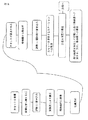
図1A及び図1Bには、本明細書中に記述された上記方法に対する作業の流れの一実施形態が更に詳細に示される。試薬カセットは、情報を記憶するタグを備えて成る。上記情報は、一実施形態においては異なる温度の複数の区画における供与時間である供与時間に関する情報から成る。上記タグはRFIDタグである。試薬カセットは、上記分析器上に装填されると共に、本明細書中に記述された試薬格納器内に格納される。装填時には上記タグに対して装填フラグが書き込まれることで、装填日付が記憶される。上記制御システムは、試薬カセット内に収容された単一種類又は複数種類の試薬の種類と、上記格納器内における該試薬カセットの箇所とに関する情報を記憶する。上記分析システムにより要求される試薬に関する情報の受信時に、上記操作器システムは、要求された単一又は複数のカセットを取出し、それを、試薬カセットを分析器に対して呈示するステーションまで搬送する。上記タグ上のカウンタは、今やトリガされることで、上記試薬格納器の外部にて費やされる時間の間において段減的にカウントを行う。代替的に、上記タグに対しては供与タイムスタンプが書き込まれても良い。上記試薬カセットは今や、試薬カセットを分注デバイスに対して呈示するステーションまで、又は、本明細書中に記述される試薬の一時的格納器まで搬送される。もし、上記試薬カセットが、試薬カセットを分注デバイスに対して呈示するステーションまで搬送されるなら、該試薬カセットは、使用後には上記試薬格納器まで戻されるか、又は、廃棄物ステーションへと移送される。もし上記試薬カセットが上記試薬格納器へと戻し移送されるなら、上記タグに対しては供与タイムスタンプが書き込まれ得る。その後、上記プロセスは反復され得る。 1A and 1B illustrate in more detail one embodiment of a workflow for the above method described herein. The reagent cassette includes a tag for storing information. The information consists of information regarding dispensing time, which in one embodiment is dispensing time in multiple compartments at different temperatures. The tag is an RFID tag. Reagent cassettes are loaded onto the analyzer and stored in the reagent store described herein. At the time of loading, a loading date is stored by writing a loading flag to the tag. The control system stores information related to the type of single type or plural types of reagents accommodated in the reagent cassette and the location of the reagent cassette in the storage. Upon receipt of information about the reagents required by the analysis system, the controller system removes the requested cassette or cassettes and transports them to a station that presents the reagent cassettes to the analyzer. The counter on the tag is now triggered to count down the time spent outside the reagent store. Alternatively, a donation time stamp may be written to the tag. The reagent cassette is now transported to a station that presents the reagent cassette to the dispensing device or to a temporary reservoir of reagents as described herein. If the reagent cassette is transported to a station that presents the reagent cassette to the dispensing device, the reagent cassette is returned to the reagent storage after use or transferred to a waste station. Is done. If the reagent cassette is transferred back to the reagent store, a donation time stamp can be written to the tag. The process can then be repeated.
上記試薬カセットが上記一時的格納器へと搬送されるとして、タイムスタンプが供与時間を監視すべく使用されるなら、上記試薬カセットを上記一時的格納器内に載置する前に、上記タグに対しては供与タイムスタンプが書き込まれ得る。上記カウンタにより、上記一時的格納器における温度に従い段減カウントが行われる。上記一時的格納器における上記カセットの位置は、上記制御システムにより記憶される。もし上記システムが試薬を要求するなら、対応する試薬カセットは、試薬カセットを分注デバイスへと呈示するステーションへと移送される。上記一時的格納器の利点は、上記分注デバイスに対して試薬カセットが非常に迅速に呈示され得るということである。上記試薬カセットが、試薬カセットを呈示する上記ステーション上に配置されている間、試薬カセットを呈示する該ステーションにおける温度が上記一時的格納器におけるよりも高ければ、上記カウンタは上記一時的格納器におけるよりも高速にカウントを行う。上記試薬カセットは、再使用のために上記一時的格納器へと、又は、長時間の格納のために上記試薬格納器へと戻され得る。上記試薬格納器内での格納に先立ち、上記タグには供与タイムスタンプが書き込まれる。供与時間カウンタが更新される。上記試薬カセットはその後、それが再び要求されるまで、上記試薬格納器内に格納される。 If the reagent cassette is transported to the temporary storage, and if a time stamp is used to monitor the delivery time, before placing the reagent cassette in the temporary storage, In contrast, a donation time stamp can be written. The counter performs step-down counting according to the temperature in the temporary storage. The position of the cassette in the temporary store is stored by the control system. If the system requires a reagent, the corresponding reagent cassette is transferred to a station that presents the reagent cassette to the dispensing device. The advantage of the temporary storage is that the reagent cassette can be presented very quickly to the dispensing device. While the reagent cassette is positioned on the station presenting the reagent cassette, if the temperature at the station presenting the reagent cassette is higher than in the temporary store, the counter is in the temporary store. Count faster than. The reagent cassette can be returned to the temporary store for reuse or to the reagent store for extended storage. Prior to storage in the reagent store, a donation time stamp is written to the tag. The donation time counter is updated. The reagent cassette is then stored in the reagent store until it is requested again.
合計の供与時間が所定値を超過したなら、又は、上記試薬カセットにおける試薬レベルが低すぎるなら、又は、上記試薬カセットが誤りであるなら、それは、廃棄物ステーションへと、又は、手動的な取り外しのために投入/取出し位置へと搬送される。 If the total dispensing time exceeds a predetermined value, or if the reagent level in the reagent cassette is too low, or if the reagent cassette is incorrect, it can be removed to a waste station or manually removed. To the loading / unloading position.
故に、本明細書中に記述された上記分析システムは、(図11に示された如き)読取り/書込みデバイス1160を備えて成る。 Thus, the analysis system described herein comprises a read / write device 1160 (as shown in FIG. 11).
また、本明細書中に記述された如く分析対象物を単離及び/又は分析する分析器及びシステムであって、本明細書中に記述された如き試薬格納器を備えて成る分析器及びシステムもまた、本発明の技術的範囲内である。 An analyzer and system for isolating and / or analyzing an analyte as described herein, comprising a reagent store as described herein. Is also within the scope of the present invention.
更に、本明細書中に記述された如き試薬格納器を備えて成るシステムにおいて分析対象物を分析する方法もまた、本発明の技術的範囲内である。 Furthermore, a method for analyzing an analyte in a system comprising a reagent storage as described herein is also within the scope of the present invention.
液体サンプル内に存在し得る分析対象物を単離して分析する方法が開示される。該方法は、自動化された以下の各段階を備えて成る:
a)上記液体サンプルを、ピペット先端部によりサンプル容器から処理容器へと移し換える段階;
b)上記処理容器のウェル内において、上記分析対象物が固体支持物質上に固定化されるのを許容するに十分な時的間隔及び条件下で、上記固体支持物質及び上記液体サンプルを相互に組み合わせる段階;
c)分離ステーションにおいて、上記液体サンプル中に存在する他の物質から上記固体支持物質を単離する段階;及び、
d)上記分離ステーションにおいて、上記固体支持物質から上記液体サンプルを分離し且つ上記物質を洗浄用緩衝液により一回以上洗浄することにより、上記分析対象物を精製する段階。
A method for isolating and analyzing an analyte that may be present in a liquid sample is disclosed. The method comprises the following automated steps:
a) transferring the liquid sample from the sample container to the processing container by a pipette tip;
b) The solid support material and the liquid sample are brought together with each other under a time interval and conditions sufficient to allow the analyte to be immobilized on the solid support material in the well of the processing vessel. Combining stages;
c) isolating the solid support material from other materials present in the liquid sample at a separation station; and
d) purifying the analyte at the separation station by separating the liquid sample from the solid support material and washing the material one or more times with a wash buffer.
一実施形態において、上記処理容器は1つ以上の受容器を備えて成る。一実施形態において、上記処理容器は多重ウェル・プレートである。上記方法は一実施形態において、
e)上記精製済み分析対象物を、検出可能信号を獲得するために必要な試薬と反応させる段階、
を付加的に備えて成る。
In one embodiment, the processing vessel comprises one or more receptacles. In one embodiment, the processing vessel is a multi-well plate. In one embodiment, the method is as follows:
e) reacting the purified analyte with reagents necessary to obtain a detectable signal;
Is additionally provided.
本明細書中で用いられる「受容器」という語句は、単一の容器(又は管体)、又は、多重管体ユニット中に含まれる1つの管体、又は、多重ウェル・プレートの1つのウェル(又は容器)に関連している。 As used herein, the phrase “receptor” refers to a single container (or tube), or one tube contained in a multi-tube unit, or one well of a multi-well plate. (Or container).
また「容器」という語句は、単一の容器、又は、多重管体ユニットにおける単一の容器、多重ウェル・プレート若しくは多重管体ユニット、又は、多重ウェル・プレートの1つのウェルを意味すると理解される。 The term “container” is also understood to mean a single container, or a single container in a multi-tube unit, a multi-well plate or multi-tube unit, or one well of a multi-well plate. The
一実施形態において、上記反応段階は、検出可能信号を生成する段階を備えて成る。更に、上記方法は付加的に、検出可能信号を検出する段階を備えて成り得る。 In one embodiment, the reaction stage comprises generating a detectable signal. Furthermore, the method can additionally comprise the step of detecting a detectable signal.
本明細書中で用いられる「反応する段階」という語句は、試薬に対する上記分析対象物の任意の種類の化学反応であって、検出可能信号を獲得するために必要である化学反応に関連する。一実施形態において、上記反応段階は、増幅から成る。増幅は、信号に対する任意の種類の強化として理解され得る。故に、増幅は酵素による分子の変換であり得ると共に、その場合に上記酵素は上記分析対象物に対して連結又は結合されて検出可能信号に繋がり、分析対象物分子が存在するよりも多くの信号分子が形成される。1つの斯かる非限定的な例は、例えばECLを用いた化学発光色素の形成である。増幅という語句は更に、上記分析対象物が核酸ならば、核酸増幅に関連する。これは、線形の等温的な増幅、及び、指数的な増幅の両方を包含する。核酸増幅方法の非限定的な例は、TMA、SDA、NASBA、及び、リアルタイムPCRを含むPCRである。当業者であれば、斯かる方法は公知である。 As used herein, the phrase “reacting” refers to any type of chemical reaction of the analyte to the reagent that is necessary to obtain a detectable signal. In one embodiment, the reaction step consists of amplification. Amplification can be understood as any type of enhancement to the signal. Thus, amplification can be the conversion of a molecule by an enzyme, in which case the enzyme is linked or bound to the analyte, leading to a detectable signal and more signals than the analyte molecule is present. A molecule is formed. One such non-limiting example is the formation of chemiluminescent dyes using, for example, ECL. The phrase amplification further relates to nucleic acid amplification if the analyte is a nucleic acid. This includes both linear isothermal amplification and exponential amplification. Non-limiting examples of nucleic acid amplification methods are PCR, including TMA, SDA, NASBA, and real-time PCR. Such methods are known to those skilled in the art.
本明細書中で用いられる「固体支持体」という語句は、吸着により直接的かつ非特異的に、又は、間接的かつ特異的に分析対象物が結合し得る任意の種類の固体支持体に関連している。間接的結合は、固体支持体上に固定化された抗体に対する分析対象物の結合、又は、例えばNiキレートに対する6xHisタグの結合などの、タグ結合化合物に対するタグの結合であり得る。上記分析対象物が核酸であるとき、斯かる間接的結合は好適には、関心対象となる核酸の目標配列と同種である捕捉核酸プローブに対する結合によるものであり得る。故に、固体支持体上に取付けられた捕捉プローブを用いると、目標分析対象物、又は目標核酸は、目標でない物質、又は目標でない核酸から分離され得る。斯かる捕捉プローブは、上記固体支持体上に固定化される。固体支持物質は、一種類のポリマとされ得るか、又は、複数種類のポリマの組成物とされ得る。他の種類の固体支持物質としては、磁性シリカ粒子、金属粒子などが挙げられる。 As used herein, the phrase “solid support” refers to any type of solid support to which an analyte can bind directly and non-specifically or indirectly and specifically by adsorption. doing. Indirect binding can be binding of an analyte to an antibody immobilized on a solid support, or binding of a tag to a tag binding compound, such as binding of a 6xHis tag to a Ni chelate, for example. When the analyte is a nucleic acid, such indirect binding can preferably be due to binding to a capture nucleic acid probe that is homologous to the target sequence of the nucleic acid of interest. Thus, using a capture probe mounted on a solid support, the target analyte, or target nucleic acid, can be separated from non-target substances or non-target nucleic acids. Such a capture probe is immobilized on the solid support. The solid support material can be a single type of polymer or a composition of multiple types of polymers. Other types of solid support materials include magnetic silica particles and metal particles.
シリカ粒子に対する核酸の非特異的な結合は、カオトロピック化合物の存在下で行われる。斯かる結合はまた、本明細書中に記述される間接的結合と対照的に、直接的結合とも称される。一実施形態において、上記固体は、磁気的な又は磁化可能な物質から成るシリカ粒子を支持する。 Nonspecific binding of the nucleic acid to the silica particles takes place in the presence of a chaotropic compound. Such a bond is also referred to as a direct bond, as opposed to an indirect bond described herein. In one embodiment, the solid supports silica particles composed of a magnetic or magnetizable material.
図2は、分析器のモジュールの下側部分1100を示している。頂部には、処理プレート1101がある。下側部分1100は、フレーム1110を備えて成る。上記処理プレートは、試薬カセット1102を呈示するステーションを備えて成る。積層器ユニットのハウジング1103も示される。該積層器ユニットは更に、試薬カセットが装填される試薬引出し1104を備えて成る。次に昇降器1105は、上記カセットを、それが試薬格納器1106内へと移送され得るレベルまで移動する。上記昇降器は、Y操作器1105及びZ軸1108を備えて成る。昇降器1105のスピンドル1109も示される。試薬格納器1106の後側ドアを開くための配置機構1111も視認可能である。図3には、試薬格納器1106及び後側ドア1112、並びに冷却ユニット1115が示される。
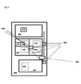
FIG. 2 shows the
図4は、試薬カセット引出し1104と、試薬格納器1106の開かれた前側ドア1125と、試薬挿入物1130を備えて成る試薬カセット1122とを示している。試薬カセット1122はY操作器1105上に位置決めされる。Y操作器1105は、試薬カセット1102を試薬格納器1106内に載置するところである。試薬格納器1106の内部は複数の回転盤1113を備えて成り、その上に、試薬カセット1122が載置されて位置決めされ得る。各回転盤1113は、内部にカセット1102が位置決めされる中心合わせブロック1114を備えて成る。中心合わせブロック1114の好適な個数は、4個のブロック1114である。
FIG. 4 shows a
図12には、核酸に基づく増幅反応を実施する際に使用される自動分析器400も開示される。該分析器は、複数のモジュール401、402、403を備えて成る。1つのモジュールは、該分析器内の第1箇所に配設された処理モジュールであって、サンプル中の他の物質から核酸を分離すべく構成かつ配置された処理モジュールである。該処理モジュールは、本明細書において記述される如き分離デバイスを備えて成る。上記分析器は、該分析器内の第2箇所に配設かつ配置された増幅モジュールを更に備えて成る。該増幅モジュールは、好適には分離済み核酸を備えて成る多重ウェル・プレートの少なくとも1つの受容器の内容物と、サンプル中の目標核酸を表す増幅生成物を生成する一種類以上の増幅試薬とを保温する温度制御式の保温器を備えて成る。
FIG. 12 also discloses an
図10に依れば、分析対象物を処理する分析システム440は、
a)液体サンプル1010を収容すると共に線形配置された複数の第1受容器1001と、液体サンプル1011を保持するn×mの配列の複数の受容器103を備えて成る処理プレート101と、線形配置とされた少なくとも2個の分注ユニット702を備えて成る第1分注デバイス700であって、上記分注ユニット702はピペット先端部3、4に対して結合される第1分注デバイス700と、a×(n×m)の配列の複数のピペット先端部3、4を備えて成る先端部用ラック70と、を備えて成る第1位置と、
b)上記処理プレート101に対するホルダ201、128と、上記先端部用ラック70に対するホルダ470と、ピペット先端部3、4(図10)に対して結合すべくn×mの配列の複数の分注ユニット702を備えて成る第2分注デバイス35と、を備えて成る第2位置と、を備えて成る。
本明細書中で用いられる如く、「ホルダ」という語句は、ラック又は処理プレートを受容し得る一切の配置機構に関している。
According to FIG. 10, the
a) a
b) Multiple dispenses in an nxm array to be coupled to
As used herein, the phrase “holder” relates to any placement mechanism that can receive a rack or processing plate.
本発明の分析システム440の利点は、本発明の上記方法に対して本明細書中に記述されたのと同様である。
The advantages of the
分析システム440の利点は、本明細書中に記述された如くである。
The advantages of
一実施形態において、第1分注デバイス700の各分注ユニット702の位置は可変的である。上記第1分注デバイス700の各実施形態は、本明細書中に記述される。
In one embodiment, the position of each dispensing unit 702 of the
一実施形態において、先端部用ラック70は、a×(n×m)の配列とされた複数のピペット先端部3、4を備えて成る。一実施形態においては、先端部用ラック70内に第1形式4及び第2形式3のピペット先端部が含まれる。この実施形態において、第1形式のピペット先端部4はn×mの配列で配置され、且つ、第2形式のピペット先端部3は上記n×mの配列で配置される。一実施形態において、第1形式のピペット先端部4は、第2形式のピペット先端部3とは異なる容量を有する。一実施形態において、第1形式のピペット先端部4の容量は500μlより多く、且つ、第2形式のピペット先端部3の容量は500μlより少ない。この実施形態においては、a=2である。しかし、2種類より多いピペット先端部を備えることからa>2である本発明の実施形態もまた、本発明に包含される。 In one embodiment, the tip rack 70 comprises a plurality of pipette tips 3, 4 arranged in an a × (n × m) array. In one embodiment, the tip type rack 70 includes first type 4 and second type 3 pipette tips. In this embodiment, the first type pipette tips 4 are arranged in an n × m arrangement, and the second type pipette tips 3 are arranged in the n × m arrangement. In one embodiment, the first type pipette tip 4 has a different volume than the second type pipette tip 3. In one embodiment, the volume of the first type pipette tip 4 is greater than 500 μl and the volume of the second type pipette tip 3 is less than 500 μl. In this embodiment, a = 2. However, embodiments of the present invention in which a> 2 since more than two pipette tips are provided are also encompassed by the present invention.
1つの態様において、本発明の分析システム440は、サンプルの種類及び個々の試験を上記処理プレート101の個々の位置に対して割当てる制御ユニット1006を備えて成る。好適には、上記各位置は別体的な区画401、402である。
In one embodiment, the
本発明の1つの態様において、上記システムは付加的に、第1位置402と第2位置401との間において処理プレート101及びラック70を移送する移送システム480を備えて成る。移送システム480の実施形態は、コンベア・ベルト、又は、1つ以上の操作器である。
In one aspect of the invention, the system additionally comprises a
更に、第2分注デバイス35の各分注ユニットは、第1位置402において使用されたピペット先端部3、4に対して係合される。
Furthermore, each dispensing unit of the
本明細書中に記述されたシステム440の一実施形態は付加的に、検出可能信号を獲得するために必要な試薬と共に上記分析対象物を保温する温度制御式の保温器を備えて成る第3ステーション403を備えて成る。第3ステーション403の更なる実施形態は、熱ブロックを備えて成る増幅ステーションである。各サンプル及び試験を上記のn×mの配列で割当てる更に最適な制御は、第1位置402に含まれた第1プロセッサ1004であって、該第1プロセッサに対しては、処理プレート101の容器103のn×mの配列における特定の複数の位置に対してサンプルの種類及び個々の試験を割当てる命令を制御ユニット1006が伝達する第1プロセッサ1004と、第2位置401に含まれた第2プロセッサ1005であって、該第2プロセッサに対しては、上記処理プレートの容器103のn×mの配列における特定の複数の位置に対してサンプルの種類及び個々の試験を割当てる命令を制御ユニット1006が伝達する第2プロセッサ1005と、により達成される。
One embodiment of the
一実施形態において上記システムは付加的に、上記第1位置に配置された第1プロセッサと、上記第2位置に配置された第2プロセッサとを備えて成る。 In one embodiment, the system additionally comprises a first processor located at the first location and a second processor located at the second location.
一実施形態において、第1プロセッサ1004は第1分注デバイス700を制御し、且つ、第2プロセッサ1005は第2分注デバイス35を制御する。
In one embodiment, the
一時的格納器
本開示内容はまた、分析対象物を単離及び/又は分析する自動分析器であって、液体を移送するユニットであって、少なくとも1つの試薬カセットを分注デバイスに対して呈示するステーションを備えて成るユニットを備えて成る自動分析器にも関する。該分析器は付加的に、分析対象物を分析するユニットを備えて成る。更に、上記分析器は、上記分析対象物を単離及び/又は分析するために必要な試薬を収容する少なくとも1つの試薬カセットの一時的格納のためのユニットも備えて成る。
Temporary Enclosure The present disclosure also provides an automated analyzer for isolating and / or analyzing an analyte, a unit for transferring a liquid, presenting at least one reagent cassette to a dispensing device It also relates to an automatic analyzer comprising a unit comprising a station for carrying out. The analyzer additionally comprises a unit for analyzing the analyte. The analyzer further comprises a unit for temporary storage of at least one reagent cassette containing the reagents necessary for isolating and / or analyzing the analyte.
上記一時的格納によれば、各試薬カセットが上記分析器により必要とされる間はそれらを格納し、且つ、それらがもはや必要とされないときにはそれらを取出すことが可能とされる。 The temporary storage allows each reagent cassette to be stored while it is needed by the analyzer and to be removed when they are no longer needed.
一実施形態において、液体を移送する上記ユニットは付加的に、分析対象物を単離する少なくとも1つのステーションを備えて成る。分析対象物を単離する上記ステーショの実施形態は、本明細書中に記述される。液体を移送する上記ユニット、及び、少なくとも1つの試薬カセットの一時的格納のための上記ユニットは好適には、少なくとも部分的に重なり合う。一実施形態において、分注デバイスに対して少なくとも1つの試薬カセットを呈示する上記ステーションは、上記重なり合い領域内に配置される。液体を移送する上記ユニットが少なくとも1つの分注デバイスを備えて成ることは理解される。一実施形態において、分注デバイスに対して少なくとも1つの試薬カセットを呈示する上記ステーションは、上記一時的格納器の外部に配置される。一実施形態において、上記重なり合い領域は昇降器プレートを備えて成る。 In one embodiment, the unit for transporting liquid additionally comprises at least one station for isolating the analyte. Embodiments of the above station for isolating an analyte are described herein. The unit for transferring liquid and the unit for temporary storage of at least one reagent cassette preferably overlap at least partially. In one embodiment, the station presenting at least one reagent cassette to the dispensing device is located in the overlap region. It is understood that the unit for transferring liquid comprises at least one dispensing device. In one embodiment, the station presenting at least one reagent cassette to the dispensing device is located external to the temporary storage. In one embodiment, the overlap region comprises an elevator plate.
本開示内容の更なる態様において、上記分析器は付加的に、分析対象物を含むサンプルを第1受容器から第2受容器へと移送するユニットを備えて成る。本開示内容の1つの態様において、上記分析器は付加的に、密閉式の試薬格納器を備えて成る。 In a further aspect of the present disclosure, the analyzer additionally comprises a unit for transferring a sample containing the analyte from the first receiver to the second receiver. In one aspect of the present disclosure, the analyzer additionally comprises a sealed reagent store.
上記分析器の実施形態において、一時的格納のための上記ユニットは、冷却ユニットを備えて成る。上記一時的格納ユニットの更なる実施形態は、本明細書中に開示される。 In the analyzer embodiment, the unit for temporary storage comprises a cooling unit. Further embodiments of the temporary storage unit are disclosed herein.
上記密閉式の試薬格納器の実施形態は、本明細書中に記述される。上記密閉式の試薬格納器の上記冷却ユニットは、該密閉式の試薬格納器の内部温度を、下側の指定温度と上側の指定温度との間に維持すべく設定される。上記温度の実施形態は、本明細書中に開示される。 Embodiments of the closed reagent store are described herein. The cooling unit of the sealed reagent container is set to maintain the internal temperature of the sealed reagent container between a lower designated temperature and an upper designated temperature. Embodiments of the above temperatures are disclosed herein.
上記密閉式の試薬格納器は特に有用である、と言うのも、それは温度に影響されやすい試薬の長期の格納を提供するからである。斯かる試薬としては、限定的なものとしてでは無く、核酸を増幅するためのポリメラーゼの如き酵素、又は、呈色反応のための酵素を含む試薬が挙げられる。本開示内容に係る、試薬の長期の格納のための試薬格納器と、一時的格納器との組み合わせは、分析システムにおいて特に好適である。これにより、試薬カセット及びその内容物が、格納温度を超える温度に晒される時間が最小限まで減少される。斯かる分析器及びシステムにおいて、試薬を備えた試薬カセットが装填される頻度が減少され得ることから、操作者が離れる時間が増大される。試薬カセットを上記試薬格納器から上記一時的格納器へと移し換えることにより、各試薬カセットは、それらが上記試薬格納器から直接的に移送される場合よりも、更に迅速に上記分注デバイスに対して呈示される。これにより上記試薬格納器は、スペースが容易に利用可能である上記分析器の領域に載置され得る。上記一時的格納ユニットの各寸法は、現在の作業に必要な試薬カセットを格納するために必要なスペースまで低減され得ることから、上記一時的格納ユニットにより占有されるスペースを最小化し乍ら、それを、液体を移送する上記ユニットの直近に載置することが可能とされる。この設定は、夫々の試薬が必要とされるときに試薬カセットを分注デバイスに対して迅速かつ適時に呈示するために特に好適である。 The sealed reagent store is particularly useful because it provides long-term storage of the temperature sensitive reagent. Such a reagent includes, but is not limited to, an enzyme such as a polymerase for amplifying a nucleic acid or a reagent containing an enzyme for a color reaction. The combination of a reagent store for long-term storage of reagents and a temporary store according to the present disclosure is particularly suitable in an analysis system. This minimizes the time that the reagent cassette and its contents are exposed to temperatures above the storage temperature. In such analyzers and systems, the frequency with which reagent cassettes with reagents are loaded can be reduced, thus increasing the time for the operator to leave. By transferring reagent cassettes from the reagent store to the temporary store, each reagent cassette can be transferred to the dispensing device more quickly than if they were transferred directly from the reagent store. Presented to. This allows the reagent store to be placed in the area of the analyzer where space is readily available. Each dimension of the temporary storage unit can be reduced to the space required to store the reagent cassettes required for the current operation, thus minimizing the space occupied by the temporary storage unit. Can be placed in the immediate vicinity of the unit for transferring the liquid. This setting is particularly suitable for presenting reagent cassettes quickly and in a timely manner to the dispensing device when each reagent is needed.
上記一時的格納器は、更なる利点を有している。1つの態様において、それは冷却ユニットを備えた密閉式の冷却領域を備えて成る。1つの態様において、上記冷却は能動的冷却ユニットである。該冷却ユニットは、温度を閾温度より低く維持すべく設定される。一実施形態において、上記閾温度は、40℃、更に好適には35℃又は30℃、最も好適には28℃である。上記冷却ユニットは、温度を斯かる閾値より低く維持すべく動作することのみが必要である。故に、上記試薬格納器に対するよりも少ないエネルギが必要とされる。他方、各試薬の寿命は最適化される、と言うのも、それらは、それらが必要とされる限りにおいてのみ上記一時的格納器内に保持されてから、長期の格納のために上記試薬格納器へと戻されるからである。故に、高温に対する露出が最小限とされる一方、分注デバイスに対する試薬カセットの迅速かつ適時の呈示が維持される。 The temporary store has a further advantage. In one embodiment, it comprises an enclosed cooling area with a cooling unit. In one embodiment, the cooling is an active cooling unit. The cooling unit is set to keep the temperature below the threshold temperature. In one embodiment, the threshold temperature is 40 ° C, more preferably 35 ° C or 30 ° C, most preferably 28 ° C. The cooling unit need only operate to keep the temperature below such a threshold. Therefore, less energy is required than for the reagent store. On the other hand, the lifetime of each reagent is optimized, because they are retained in the temporary enclosure only as long as they are needed and then stored in the reagent for long-term storage. Because it is returned to the vessel. Thus, rapid and timely presentation of the reagent cassette to the dispensing device is maintained while exposure to high temperatures is minimized.
密閉式の試薬格納器の実施形態は、本明細書中に記述される。 Embodiments of sealed reagent stores are described herein.
本発明の1つの好適な態様において、上記分析器は付加的に、上記密閉式の試薬格納器と、試薬カセットを呈示する上記ステーションとの間における上記試薬カセットの双方向搬送のための操作器システムを備えて成る。更なる好適実施形態は、本明細書中に記述される。 In one preferred embodiment of the present invention, the analyzer additionally comprises an operator for bidirectional transport of the reagent cassette between the sealed reagent storage and the station presenting the reagent cassette. Comprising a system. Further preferred embodiments are described herein.
本発明はまた、自動分析器において分析対象物を分析するための試薬を収容する試薬カセットを分注デバイスへと呈示する方法であって、
能動的冷却を行う密閉式の試薬格納器内に格納された試薬カセットを、一時的格納ユニットへと移送する段階と、
上記分析器により上記試薬カセットが必要とされるまで、それを上記一時的格納ユニット内に保持する段階と、
上記一時的格納ユニットから上記試薬カセットを、該試薬カセットを上記分注デバイスへと呈示するステーションへと移送する段階であって、上記少なくとも1つの試薬カセットを呈示する上記ステーションは上記一時的格納器の外部に配置される段階と、
上記試薬の分注が完了したときに、上記試薬カセットを上記一時的格納ユニットへと戻し移送する段階とを備えて成る、
方法にも関している。
The present invention is also a method for presenting to a dispensing device a reagent cassette containing a reagent for analyzing an analyte in an automatic analyzer,
Transferring a reagent cassette stored in an enclosed reagent container for active cooling to a temporary storage unit;
Holding the reagent cassette in the temporary storage unit until the analyzer requires the reagent cassette;
Transferring the reagent cassette from the temporary storage unit to a station for presenting the reagent cassette to the dispensing device, wherein the station for presenting the at least one reagent cassette is the temporary container; The stage of being placed outside the
Transporting the reagent cassette back to the temporary storage unit when dispensing of the reagent is complete,
It also relates to the method.
斯かる方法は好適である、と言うのも、試薬を収容する各試薬カセットは、それらが必要とされる間のみ、上記分析器内における高温領域に晒される一方、それらが分注に対して必要とされたときには迅速に起動され得るからである。 Such a method is preferred because each reagent cassette containing a reagent is exposed to the hot area in the analyzer only while they are needed, while they are not subject to dispensing. This is because it can be activated quickly when needed.
1つの態様において、段階b)〜d)は、少なくとも一回だけ反復される。一実施形態において、上記試薬カセットは上記密閉式の試薬格納器から上記一時的格納ユニットへと、操作器システムにより移送される。 In one embodiment, steps b) to d) are repeated at least once. In one embodiment, the reagent cassette is transferred from the sealed reagent storage to the temporary storage unit by an operator system.
一実施形態において、上記試薬カセットは、上記密閉式の試薬格納器から第1操作器により第1位置へと移送され、且つ、該第1位置から第2操作器により上記一時的格納器へと移送される。 In one embodiment, the reagent cassette is transferred from the sealed reagent storage to the first position by the first controller, and from the first position to the temporary storage by the second controller. Be transported.
1つの態様において、上記試薬カセットは情報を記憶するタグを備えて成り、該タグには、上記自動分析器における供与時間の情報が記憶される。 In one embodiment, the reagent cassette is provided with a tag for storing information, and the tag stores information on the dispensing time in the automatic analyzer.
好適実施形態において、本明細書中に記述された上記方法は、もし上記試薬カセットが空でなければ、該試薬カセット内に収容された試薬が新たな試験に対して要求されるまで長期の格納のために該試薬カセットを上記密閉式の試薬格納器へと移送し、又は、上記試薬カセットを消耗品廃棄ステーションへと移送する段階を付加的に備えて成る。上記試薬カセットは付加的に、上記密閉式の試薬格納器の引出し内へと好適には手動的に装填され、上記試薬カセットは上記密閉式の試薬格納器内で自動的に移送される。 In a preferred embodiment, the method described herein provides for prolonged storage until the reagent contained in the reagent cassette is required for a new test if the reagent cassette is not empty. For this purpose, the method further comprises the step of transferring the reagent cassette to the sealed reagent storage or transferring the reagent cassette to a consumable disposal station. In addition, the reagent cassette is preferably manually loaded into the drawer of the sealed reagent container, and the reagent cassette is automatically transferred into the sealed reagent container.
一実施形態において、上記一時的格納器内の上記試薬カセットは、該試薬カセットを分注デバイスへと呈示する上記ステーションへと、昇降器により移送される。 In one embodiment, the reagent cassette in the temporary storage is transported by an elevator to the station that presents the reagent cassette to a dispensing device.
更なる好適実施形態は、本明細書中に記述される。 Further preferred embodiments are described herein.
本発明の上記分析器、及び、その構成要素、特に上記一時的格納ユニットの代表的実施形態は、本明細書中に示される。 An exemplary embodiment of the analyzer of the present invention and its components, particularly the temporary storage unit, is presented herein.
一実施形態において、本明細書中に記述された上記方法は付加的に、もし上記試薬カセットが空でなければ、該試薬カセット内に収容された試薬が新たな試験に対して要求されるまで長期の格納のために該試薬カセットを上記密閉式の試薬格納器へと移送し、又は、上記試薬カセットを消耗品廃棄ステーションへと移送する段階を備えて成る。上記試薬カセットは付加的に、上記密閉式の試薬格納器の引出し内へと手動的に装填され、上記試薬カセットは上記密閉式の試薬格納器内で自動的に移送される。 In one embodiment, the method described herein additionally provides that if the reagent cassette is not empty, the reagent contained in the reagent cassette is required for a new test. Transferring the reagent cassette to the sealed reagent container for long-term storage, or transferring the reagent cassette to a consumable disposal station. In addition, the reagent cassette is manually loaded into the drawer of the sealed reagent container, and the reagent cassette is automatically transferred into the sealed reagent container.
更なる実施形態は、本明細書中に記述される。 Further embodiments are described herein.
本明細書中に開示された如き上記分析器、及び、その構成要素、特に上記一時的格納ユニットの実施形態は、本明細書中に示される。 Embodiments of the analyzer as disclosed herein, and its components, particularly the temporary storage unit, are presented herein.
図5は、分析器のモジュールであって、一実施形態においては処理モジュール402(図10)であるモジュールの下側部分1149を示している。下側部分1149の頂部は、処理プレート1150である。上記下側部分は更に、フレーム1157を備えて成る。積層器1151も示される。処理プレート1150は、(例えば図4に示された)試薬カセット1122を分注デバイスに対して呈示するステーション1156と、試薬カセット1122を分注デバイスに対して呈示する該ステーション1156の内側における昇降器プレート1152とを備えて成る。試薬カセット1122は、情報を記憶するタグ1160を備えて成る。昇降器プレート1152は、Z方向に移動され得る。一時的格納器1153も示される。図6は、一時的格納器1153と、試薬カセットを分注デバイスへと呈示するステーション1156と、上記格納物を取出すための緊急ドア1154と、空気吐出口1147とを示している。図7は、緊急ドア1154が取り外されると共に、カセット1102を一時的格納器1153の内側に保持する保持ユニット1155及びカセット1122が視認され得ることを除き、図6と同一の特徴を示している。図8及び図9には、上記一時的格納器の内側が示される。図8は、フレーム1158と、保持ユニット1155と、該保持ユニット内に保持された試薬カセット1122と、試薬カセット1122を呈示するステーション1156と、昇降器プレート1152とを示している。特に、図9は昇降器1159も示している。
FIG. 5 shows the
分析対象物を単離かつ分析する分析装置及び方法
流体サンプル中に存在し得る分析対象物を単離かつ分析する方法が開示される。該方法は、自動化された以下の各段階を備えて成る:
f)上記流体サンプルを、ピペット先端部によりサンプル容器から処理容器へと移し換える段階;
g)上記処理容器のウェル内において、上記分析対象物が固体支持物質上に固定化されるのを許容するに十分な時的間隔及び条件下で、上記固体支持物質及び上記流体サンプルを相互に組み合わせる段階;
h)分離ステーションにおいて、上記流体サンプル中に存在する他の物質から上記固体支持物質を単離する段階;及び、
i)上記分離ステーションにおいて、上記固体支持物質から上記流体サンプルを分離し且つ上記物質を洗浄用緩衝液により一回以上洗浄することにより、上記分析対象物を精製する段階。
Analytical apparatus and method for isolating and analyzing an analyte A method for isolating and analyzing an analyte that may be present in a fluid sample is disclosed. The method comprises the following automated steps:
f) transferring the fluid sample from the sample container to the processing container by a pipette tip;
g) The solid support material and the fluid sample are brought together with each other at a time interval and under conditions sufficient to allow the analyte to be immobilized on the solid support material in the well of the processing vessel. Combining stages;
h) isolating the solid support material from other materials present in the fluid sample at a separation station; and
i) purifying the analyte by separating the fluid sample from the solid support material and washing the material one or more times with a wash buffer at the separation station.
1つの態様において、段階a)において使用された上記ピペット先端部は、該段階a)の後で再使用される。 In one embodiment, the pipette tip used in step a) is reused after step a).
本明細書において上記された方法の好適実施形態において、段階a)は、
a1)第1位置においてラック内に保持された第1形式の各ピペット先端部を、第1処理ヘッドに対して係合させる段階;
a2)第1処理ヘッドに対して係合された第1形式の各ピペット先端部により、上記流体サンプルをサンプル容器から処理容器へと移し換える段階;
a3)上記各ピペット先端部を上記ラック内に載置し、且つ、各ピペット先端部を上記処理ヘッドから係合解除する段階;
a4)上記各ピペット先端部を備えて成る上記ラックと、上記処理容器とを、第2位置へと搬送する段階;
a5)上記ラック内に保持された上記第1形式の各ピペット先端部を、上記第2位置において第2処理ヘッドに対して係合させる段階;
を更に備えて成り得る。
In a preferred embodiment of the method described herein above, step a) comprises
a1) engaging each pipette tip of the first type held in the rack in the first position with respect to the first processing head;
a2) transferring the fluid sample from the sample container to the processing container with each first type pipette tip engaged to the first processing head;
a3) placing each pipette tip in the rack and disengaging each pipette tip from the processing head;
a4) transporting the rack including the pipette tips and the processing container to a second position;
a5) engaging each pipette tip of the first type held in the rack with the second processing head at the second position;
Can be further provided.
一実施形態において、上記処理容器は1つ以上の受容器を備えて成り得る。1つの態様において、上記処理容器は多重ウェル・プレートである。上記方法は好適には、
j)上記精製済み分析対象物を、検出可能信号を獲得するために必要な試薬と反応させる段階、
を付加的に備えて成る。
In one embodiment, the processing vessel may comprise one or more receptacles. In one embodiment, the processing vessel is a multi-well plate. The above method is preferably
j) reacting the purified analyte with reagents necessary to obtain a detectable signal;
Is additionally provided.
各ピペット先端部の再使用は、上記分析方法において使用される使い捨て可能な消耗品の減少と、コスト削減とに繋がる。一実施形態において、段階d)における洗浄は、各ピペット先端部に対して係合された処理ヘッドにより吸引し、且つ、上記洗浄用緩衝液を供与する段階を備えて成る。 Reuse of each pipette tip leads to a reduction in disposable consumables used in the analysis method and cost reduction. In one embodiment, the washing in step d) comprises the steps of aspiration with a processing head engaged to each pipette tip and dispensing the washing buffer.
一実施形態において、上記反応段階は、検出可能信号を生成する段階を備えて成る。1つの態様において、上記方法は付加的に、検出可能信号を検出する段階を備えて成る。 In one embodiment, the reaction stage comprises generating a detectable signal. In one embodiment, the method additionally comprises detecting a detectable signal.
本明細書中に記述された上記方法の一実施形態において、上記各ピペット先端部を備えて成る上記ラックと、上記処理容器とを、第2位置へと搬送する段階は、分析機器の別体的な第1区画と、上記分析システムの処理区画とされ得る別体的な第2区画と、の間で行われる。1つの態様において、上記ラックは複数のピペット先端部を夫々収容する複数の独立的なチャンバを備えて成る。 In one embodiment of the method described herein, the step of transporting the rack comprising each pipette tip and the processing vessel to a second position is a separate part of the analytical instrument. Between the primary first compartment and a separate second compartment that may be the processing compartment of the analysis system. In one embodiment, the rack comprises a plurality of independent chambers each housing a plurality of pipette tips.
一実施形態において、上記第1形式のピペット先端部は、段階d)における洗浄に対して再使用される。 In one embodiment, the first type of pipette tip is reused for cleaning in step d).
一実施形態において、上記ラックは付加的に、第2形式のピペット先端部を備えて成る。更に、1つの態様において、本明細書中に記述された方法は、段階d)とe)との間において磁性粒子から分析対象物が溶出される段階を備えて成る。一実施形態は、上記第2形式の複数のピペット先端部により、好適には多重ウェル・プレートである上記処理容器から、好適には多重ウェル・プレートである反応容器への分析対象物の移し換えを備えて成る。 In one embodiment, the rack additionally comprises a second type of pipette tip. Further, in one embodiment, the method described herein comprises the step of eluting the analyte from the magnetic particles between steps d) and e). In one embodiment, transfer of analyte from the processing vessel, preferably a multi-well plate, to the reaction vessel, preferably a multi-well plate, by a plurality of pipette tips of the second type. Comprising.
本開示内容は、
a)分析対象物を含む液体サンプルを保持する第1受容器と、液体サンプルを保持するための第2受容器と、複数のピペット先端部を保持するラックと、上記第1受容器から第2受容器へと液体サンプルを移し換える第1処理ヘッドとを構成する第1位置と、
b)上記第2受容器を受容するステーションと、上記ラックを受容するラック保持ステーションとを構成する第2位置と、
c)上記第2受容器と複数のピペット先端部を保持する上記ラックとを、上記第1位置と上記第2位置との間で移送する移送システムと、
を備えて成る、分析対象物を単離する分析システムを記述する。
This disclosure
a) a first receiver for holding a liquid sample containing an analyte; a second receiver for holding a liquid sample; a rack for holding a plurality of pipette tips; and a second from the first receiver. A first position defining a first processing head for transferring a liquid sample to a receiver;
b) a second position constituting a station for receiving the second receptacle and a rack holding station for receiving the rack;
c) a transfer system for transferring the second receptacle and the rack holding a plurality of pipette tips between the first position and the second position;
An analytical system for isolating an analyte comprising:
一実施形態において、上記各位置は夫々、別体的区画である。上記移送システムにより移送される上記ラックは、上記第1位置において使用された複数のピペット先端部を備えて成る。一実施形態において、上記第1受容器はサンプル容器であり且つ上記第2受容器は処理容器である。1つの態様において、上記処理容器は多重ウェル容器である。上記各ステーションの実施形態は、本明細書に記述される。 In one embodiment, each of the locations is a separate compartment. The rack transferred by the transfer system comprises a plurality of pipette tips used at the first position. In one embodiment, the first receiver is a sample container and the second receiver is a processing container. In one embodiment, the processing vessel is a multi-well vessel. Embodiments of each of the above stations are described herein.
本明細書にて記述される上記分析システムにおいて、上記搬送システムは好適には、上記受容器及び上記ラックを、上記第1位置から上記第2の別体的な位置へと移送する。1つの態様において、上記第2の別体的な位置は、磁気的分離ステーションを構成する。上記分析システムは付加的に、別の態様において、増幅ステーションを備えて成る。 In the analysis system described herein, the transport system preferably transports the receiver and the rack from the first position to the second separate position. In one aspect, the second separate location constitutes a magnetic separation station. The analysis system additionally comprises, in another aspect, an amplification station.
上記システムの一実施形態の上記搬送システムは、当該分析システム内において上記ラック及び上記処理容器を把持して第1箇所から第2箇所へと搬送すべく構成かつ配置された操作器を備えて成る。操作器は、当業者に公知である。 The transport system according to an embodiment of the system includes an operation device configured and arranged to grip the rack and the processing container in the analysis system and transport the rack from the first location to the second location. . Manipulators are known to those skilled in the art.
一実施形態において、上記システムは完全に自動化される。 In one embodiment, the system is fully automated.
本開示内容はまた、分析対象物を単離かつ分析する自動分析器であって、該分析器内に配設された複数のステーションを備えて成る自動分析器にも関している。上記複数のステーションは、第1箇所に配設されたサンプル供与ステーションを備えて成る。1つの態様において、上記サンプル供与ステーションは、分析対象物を含む液体サンプルを、ラック内に保持された各ピペット先端部によりサンプル容器から処理容器へと供与すべく構成かつ配置される。1つの態様において、サンプル供与ステーションは、サンプル容器と、処理容器と、液体供与ユニットとを備えて成るステーションである。上記液体供与ユニットは、処理デバイスとされ得る。 The present disclosure also relates to an automatic analyzer for isolating and analyzing an analyte comprising a plurality of stations disposed within the analyzer. The plurality of stations comprise a sample dispensing station disposed at a first location. In one embodiment, the sample dispensing station is constructed and arranged to dispense a liquid sample containing an analyte from a sample container to a processing container with each pipette tip held in the rack. In one embodiment, the sample dispensing station is a station comprising a sample container, a processing container, and a liquid dispensing unit. The liquid dispensing unit can be a processing device.
上記自動分析器は、第2箇所に配設された分離ステーションを更に備えて成る。1つの態様において、上記分離ステーションは、上記液体サンプルを保持している上記処理容器と、上記サンプル供与ステーションにおいて使用された複数のピペット先端部を保持する上記ラックとを受容すべく、且つ、上記液体サンプル中に存在する他の物質から分析対象物を分離すべく、構成かつ配置される。分離ステーションの別の実施形態は、可動磁石を備えて成る分離ステーションである。 The automatic analyzer further comprises a separation station disposed at the second location. In one aspect, the separation station receives the processing vessel holding the liquid sample and the rack holding a plurality of pipette tips used in the sample dispensing station, and Configured and arranged to separate the analyte from other materials present in the liquid sample. Another embodiment of the separation station is a separation station comprising a movable magnet.
上記自動分析器は第3箇所に配設された反応ステーションを更に備えて成り、該反応ステーションは、上記分析対象物を分析して検出可能信号を獲得すべく構成かつ配置される。反応ステーションの別の実施形態は、保温器を備えて成るステーションである。1つの態様において、上記保温器は温度制御式の保温器である。別の態様において、上記保温器は1つの一定温度に保持される。保温器の別の実施形態は、熱サイクラ・ブロックである。1つの態様において、上記反応ステーションに対し、又は、上記保温器に対し、検出可能信号を検出する検出器が一体的に接続される。検出器の一実施形態は、周期的な測定及び定量のための核酸定量システムを備えて成る。1つの態様において、上記検出器は付加的に、信号を検出する核酸検出システムであって、閾値レベルを超える信号が検出されたか否かに基づいて反応受容器内の核酸の有無を確定するシステムを備えて成る。 The automatic analyzer further comprises a reaction station disposed at a third location, the reaction station being configured and arranged to analyze the analyte and obtain a detectable signal. Another embodiment of the reaction station is a station comprising a warmer. In one embodiment, the incubator is a temperature-controlled incubator. In another aspect, the incubator is held at one constant temperature. Another embodiment of the incubator is a thermocycler block. In one aspect, a detector for detecting a detectable signal is integrally connected to the reaction station or to the incubator. One embodiment of the detector comprises a nucleic acid quantification system for periodic measurement and quantification. In one embodiment, the detector is additionally a nucleic acid detection system for detecting a signal, wherein the presence or absence of nucleic acid in the reaction receptor is determined based on whether or not a signal exceeding a threshold level is detected. Comprising.
代替的に、上記自動分析器は付加的に、検出ステーションを備えて成る。該自動分析器は更に、搬送機構を備えて成る。該搬送機構は、消耗品を操作する操作器を備えて成る。該操作器は好適には、消耗品を各ステーション間で搬送する。一実施形態において上記搬送機構は、上記サンプル容器及び上記ラックを、上記サンプル供与ステーションから上記分離ステーションへと搬送すべく構成かつ配置される。本開示内容の上記自動分析器の更なる実施形態は、本明細書において開示された個別的な又は組み合わされた特徴である。 Alternatively, the automatic analyzer additionally comprises a detection station. The automatic analyzer further comprises a transport mechanism. The transport mechanism includes an operating device for operating consumables. The operating device preferably transports consumables between stations. In one embodiment, the transport mechanism is constructed and arranged to transport the sample container and the rack from the sample dispensing station to the separation station. Further embodiments of the automated analyzer of the present disclosure are the individual or combined features disclosed herein.
一実施形態において、本開示内容の分析装置400は分析対象物を処理する少なくとも1つのモジュール401を備えて成り、上記処理は液体の分注から成る。処理モジュール401は、
a)ピペット先端部3、4と係合する処理ヘッド35であって、該処理ヘッド35の下側表面61内に配置された位置決め要素36を備えて成る処理ヘッド35と、
b)ピペット先端部3、4を保持する先端部用ラック60、70であって、処理ヘッド35上の位置決め要素36と機械的に係合し得る位置決め要素31、32、33、34を備えて成る先端部用ラック60、70と、
を備えて成る。
In one embodiment, the
a) a
b) Tip racks 60 and 70 for holding pipette tips 3 and 4, including positioning elements 31, 32, 33 and 34 that can be mechanically engaged with positioning elements 36 on the
Comprising.
本明細書において上記された分析装置400の一実施形態において、処理モジュール401は、分析対象物の単離及び精製のためのモジュールである。故に、本明細書中で用いられる「処理」という語句は、分析対象物の単離及び/又は分離及び/又は捕捉及び/又は精製に関連すると理解される。1つの態様において、装置400は、処理のためにサンプルを調製するモジュール402を備えて成る。1つの態様において装置400は、上記分析対象物の増幅のためのモジュール403を備えて成る。一実施形態において上記装置は、増幅試薬を、格納受容器から、精製済み分析対象物を含む受容器へと移送するモジュール404を付加的に備えて成る。上記装置の更なる実施形態は、此処で本明細書において記述される。
In one embodiment of the
本開示内容はまた、核酸に基づく増幅反応を実施する際に使用される自動分析器400にも関し、該分析器は、複数のモジュール401、402、403を備えて成る。1つのモジュールは、該分析器内の第1箇所に配設された処理モジュールであって、サンプル中の他の物質から核酸を分離すべく構成かつ配置された処理モジュールである。該処理モジュールは、本明細書において記述される如き分離デバイスを備えて成る。上記分析器は、該分析器内の第2箇所に配設かつ配置された増幅モジュールを更に備えて成る。該増幅モジュールは、1つの態様において分離済み核酸を備えて成る多重ウェル・プレートの少なくとも1つの受容器の内容物と、サンプル中の目標核酸を表す増幅生成物を生成する一種類以上の増幅試薬とを保温する温度制御式の保温器を備えて成る。
The present disclosure also relates to an
本開示内容はまた、本明細書中に記述された如く保持ステーションと多重ウェル・プレート・セットとを備えて成る分析システムにも関する。一実施形態において、上記多重ウェル・プレート・セットは上記保持ステーション内に固定される。一実施形態において、上記多重ウェル・プレートは複数の凹所を備える縁部を有する基部を備えて成り、上記各凹所に対しては、上記保持ステーション上の位置決め/固定要素、1つの態様においては掛止クリップ(図47a)及びb))が接触し、該接触により上記多重ウェル・プレートの上記基部に対して下向きの圧力が及ぼされることで、上記多重ウェル・プレートは上記保持ステーションに固定される。上記分析システムの更なる実施形態は、本明細書において開示された個別的な又は組み合わされた特徴である。 The present disclosure also relates to an analytical system comprising a holding station and a multi-well plate set as described herein. In one embodiment, the multi-well plate set is fixed in the holding station. In one embodiment, the multi-well plate comprises a base having an edge with a plurality of recesses, for each recess, a positioning / fixing element on the holding station, in one aspect The latch clip (FIGS. 47a) and b)) is in contact, and the contact exerts downward pressure on the base of the multi-well plate, thereby securing the multi-well plate to the holding station. Is done. Further embodiments of the analysis system are the individual or combined features disclosed herein.
本開示内容はまた、
分析対象物を単離して精製する処理モジュールであって、複数のピペット先端部を備えて成るラックを保持する保持ステーション470を備えて成る処理モジュールであって、上記ラックは、該ラックの1つの側壁上に配置された少なくとも1つの凹所と、該ラックの逆側の第2の側壁上に配置された少なくとも1つの凹所とを備えて成り、上記保持ステーションは、固定要素、1つの態様においては掛止クリップを備えて成り、且つ、上記固定要素、又は、掛止クリップは、上記凹所の底部に対して力を及ぼすことにより該凹所と相互作用する、処理モジュールと、
上記精製済み分析対象物を、検出可能信号を獲得するために必要な試薬と反応させることにより、該分析対象物を分析するモジュール403と、
を備えて成る分析機器にも関している。
This disclosure also includes
A processing module for isolating and purifying an analyte, comprising a holding
A
It also relates to an analytical instrument comprising:
上記分析機器は、1つの態様において、液体操作モジュール404、500を付加的に備えて成る。上記分析機器の更なる実施形態は、別体的に、又は、各実施形態の組み合わせとして本明細書中に記述される。1つの態様において、本開示内容に係る上記分析機器は好適には、シール・ステーション410を付加的に備えて成る。シール・ステーション410は、処理モジュール401内に配置される。
In one embodiment, the analytical instrument additionally comprises
「モジュール」及び「区画」という語句は、本明細書においては互換的に使用される。 The terms “module” and “compartment” are used interchangeably herein.
35 第2分注デバイス
400 自動分析器
401 処理モジュール
480 移送システム
700 第1分注デバイス
1102 試薬カセット
1105 昇降器/Y操作器
1106 試薬格納器
1112 後側ドア
1115 冷却ユニット
1122 試薬カセット
1153 一時的格納器
1156 試薬カセットを呈示するステーション
1159 昇降器
1160 タグ
35
Claims (12)
前記分析対象物を単離及び/又は分析するために必要な試薬を収容する少なくとも1つの試薬カセットの一時的格納器のユニットであって、冷却ユニットを有する該一時的格納器ユニットと、
分注デバイスに対して少なくとも1つの試薬カセットを呈示するステーションを有して液体を移送する移送ユニットであって、分注デバイスに対して少なくとも1つの試薬カセットを呈示する前記ステーションが前記一時的格納ユニットの外部に配置される移送ユニットと、
前記分析対象物を分析して検出可能信号を獲得する分析ユニットと、
密閉式の試薬格納器であって、
a.該試薬格納器の能動的冷却のための冷却ユニットと、
b.内部格納/取出しシステムと、
c.試薬の投入及び取出しのための蓋体と、
d.試薬カセットの内容物を識別するための識別ユニットと、
を有する密閉式の試薬格納器と、
前記試薬カセットを前記密閉式の試薬格納器から前記一時的格納ユニットに移送する操作器システムと、
を具備する自動分析器。 An automatic analyzer for detecting or quantifying an analysis object,
A temporary containment unit of at least one reagent cassette containing reagents necessary to isolate and / or analyze the analyte, the temporary containment unit having a cooling unit;
A transfer unit for transferring liquid having a station presenting at least one reagent cassette to a dispensing device, wherein the station presenting at least one reagent cassette to a dispensing device is temporarily stored A transfer unit arranged outside the unit;
An analysis unit for analyzing the analyte to obtain a detectable signal;
A sealed reagent container,
a. A cooling unit for active cooling of the reagent reservoir;
b. An internal storage / removal system;
c. A lid for loading and unloading reagents;
d. An identification unit for identifying the contents of the reagent cassette;
A sealed reagent container having
An operating device system for transferring the reagent cassette from the sealed reagent storage to the temporary storage unit;
An automatic analyzer.
a)能動的冷却を行う密閉式の試薬格納器内に格納された試薬カセットを、一時的格納ユニットへと移送する段階であって、前記一時的格納ユニットが冷却ユニットを有する段階と、
b)前記自動分析器により前記試薬カセットが必要とされるまで、前記試薬カセットを前記一時的格納ユニット内に保持する段階と、
c)前記一時的格納ユニットから前記試薬カセットを、該試薬カセットを前記分注デバイスへと呈示するステーションへと移送する段階であって、前記少なくとも1つの試薬カセットを呈示する前記ステーションが前記一時的格納器の外部に配置される段階と、
d)前記試薬の分注が完了したときに、前記試薬カセットを前記一時的格納ユニットへと戻し移送する段階と、を含み、
前記試薬カセットが情報を記憶するタグを有し、且つ、該タグには、前記自動分析器の供与時間の情報が記憶される方法。 A method of presenting a reagent cassette containing a reagent for analyzing an analyte in an automatic analyzer to a dispensing device,
a) transferring a reagent cassette stored in an enclosed reagent reservoir for active cooling to a temporary storage unit, the temporary storage unit having a cooling unit;
b) holding the reagent cassette in the temporary storage unit until the reagent cassette is needed by the automatic analyzer;
c) transferring the reagent cassette from the temporary storage unit to a station for presenting the reagent cassette to the dispensing device, wherein the station for presenting the at least one reagent cassette is the temporary A stage placed outside the enclosure;
d) returning the reagent cassette back to the temporary storage unit when dispensing of the reagent is completed;
A method in which the reagent cassette has a tag for storing information, and the tag is used to store information on the dispensing time of the automatic analyzer.
Applications Claiming Priority (2)
| Application Number | Priority Date | Filing Date | Title |
|---|---|---|---|
| EP10192035.3 | 2010-11-22 | ||
| EP10192035.3A EP2455766B1 (en) | 2010-11-22 | 2010-11-22 | Temporary Store |
Publications (3)
| Publication Number | Publication Date |
|---|---|
| JP2012112942A JP2012112942A (en) | 2012-06-14 |
| JP2012112942A5 JP2012112942A5 (en) | 2014-11-06 |
| JP5912032B2 true JP5912032B2 (en) | 2016-04-27 |
Family
ID=43857995
Family Applications (1)
| Application Number | Title | Priority Date | Filing Date |
|---|---|---|---|
| JP2011250563A Active JP5912032B2 (en) | 2010-11-22 | 2011-11-16 | Temporary enclosure |
Country Status (3)
| Country | Link |
|---|---|
| US (2) | US20120294762A1 (en) |
| EP (1) | EP2455766B1 (en) |
| JP (1) | JP5912032B2 (en) |
Families Citing this family (3)
| Publication number | Priority date | Publication date | Assignee | Title |
|---|---|---|---|---|
| WO2013103119A1 (en) * | 2012-01-05 | 2013-07-11 | 株式会社日立ハイテクノロジーズ | Automatic analysis device and reagent processing method in automatic analysis device |
| EP3488248A4 (en) * | 2016-07-21 | 2019-09-11 | Siemens Healthcare Diagnostics Inc. | Automated clinical analyzer system and method |
| US10908174B2 (en) | 2016-09-16 | 2021-02-02 | Canon Medical Systems Corporation | Automatic analyzing apparatus |
Family Cites Families (25)
| Publication number | Priority date | Publication date | Assignee | Title |
|---|---|---|---|---|
| JPS55136957A (en) * | 1979-04-14 | 1980-10-25 | Olympus Optical Co Ltd | Automatic analyzer |
| JPS63150375U (en) * | 1987-03-23 | 1988-10-04 | ||
| JPH04106472A (en) * | 1990-08-28 | 1992-04-08 | Shimadzu Corp | Automatic chemical analyzer |
| JPH0610868U (en) * | 1992-07-08 | 1994-02-10 | 株式会社ニッテク | Liquid suction device |
| JP4434357B2 (en) * | 1999-04-27 | 2010-03-17 | 株式会社東芝 | Automatic analyzer |
| JP2002048800A (en) * | 2000-07-31 | 2002-02-15 | Olympus Optical Co Ltd | Automatic analyzer |
| JP3873039B2 (en) * | 2003-05-14 | 2007-01-24 | 株式会社日立ハイテクノロジーズ | Automatic analyzer |
| JP4033060B2 (en) * | 2003-07-17 | 2008-01-16 | 株式会社日立ハイテクノロジーズ | Automatic analyzer |
| US7169356B2 (en) * | 2003-07-18 | 2007-01-30 | Dade Behring Inc. | Random access reagent delivery system for use in an automatic clinical analyzer |
| US7029922B2 (en) * | 2003-07-18 | 2006-04-18 | Dade Behring Inc. | Method for resupplying reagents in an automatic clinical analyzer |
| US7914737B2 (en) * | 2004-07-01 | 2011-03-29 | Roche Molecular Systems, Inc. | Multi-level diagnostic apparatus with a lift system |
| EP1772736B1 (en) * | 2004-07-22 | 2013-07-03 | Wako Pure Chemical Industries, Ltd. | Analysis assisting method, analyzer, remote computer, data analyzing method, program, and reagent container |
| EP1808699A2 (en) * | 2004-12-03 | 2007-07-18 | Kabushiki Kaisha Toshiba | Clinical laboratory apparatus |
| JP5199548B2 (en) * | 2006-05-26 | 2013-05-15 | ベックマン コールター, インコーポレイテッド | Equipment management system |
| JP5122797B2 (en) * | 2006-12-06 | 2013-01-16 | 株式会社東芝 | Automatic analyzer |
| FI20075439A0 (en) * | 2007-06-12 | 2007-06-12 | Wallac Oy | Automated instrumentation and method for measuring samples |
| US8556564B2 (en) * | 2007-06-26 | 2013-10-15 | Siemens Healthcare Diagnostics Inc. | Mobile sample storage and retrieval unit for a laboratory automated sample handling worksystem |
| JP4558017B2 (en) * | 2007-07-31 | 2010-10-06 | 株式会社日立ハイテクノロジーズ | Automatic analyzer and method of using the automatic analyzer |
| JP5277245B2 (en) * | 2008-05-22 | 2013-08-28 | 株式会社日立ハイテクノロジーズ | Automatic analyzer |
| JP2009288094A (en) * | 2008-05-29 | 2009-12-10 | Toshiba Corp | Automatic analyzer |
| JP2010085249A (en) * | 2008-09-30 | 2010-04-15 | Olympus Corp | Automatic analyzer, reagent replenishing apparatus and reagent auto-loading method |
| EP2172780A1 (en) * | 2008-10-01 | 2010-04-07 | Bayer Technology Services GmbH | Apparatus for automatically performing analyses |
| JP5210800B2 (en) * | 2008-10-31 | 2013-06-12 | シスメックス株式会社 | Sample analyzer, reagent information display method and computer program in sample analyzer |
| ES2643134T3 (en) * | 2008-11-28 | 2017-11-21 | F. Hoffmann-La Roche Ag | System and method for processing liquid samples |
| JP2010237021A (en) * | 2009-03-31 | 2010-10-21 | Sysmex Corp | Analyzer |
-
2010
- 2010-11-22 EP EP10192035.3A patent/EP2455766B1/en active Active
-
2011
- 2011-11-16 US US13/297,811 patent/US20120294762A1/en active Pending
- 2011-11-16 JP JP2011250563A patent/JP5912032B2/en active Active
-
2015
- 2015-12-22 US US14/978,755 patent/US20160161518A1/en not_active Abandoned
Also Published As
| Publication number | Publication date |
|---|---|
| EP2455766B1 (en) | 2019-06-19 |
| US20120294762A1 (en) | 2012-11-22 |
| EP2455766A1 (en) | 2012-05-23 |
| JP2012112942A (en) | 2012-06-14 |
| US20160161518A1 (en) | 2016-06-09 |
Similar Documents
| Publication | Publication Date | Title |
|---|---|---|
| US10081502B2 (en) | Reagent store | |
| US10775399B2 (en) | Automated storage modules for diagnostic analyzer liquids and related systems and methods | |
| EP2546655B1 (en) | Instrument and process for the automated processing of liquid samples | |
| JP6251228B2 (en) | Method for separating and detecting analytes | |
| US6825041B2 (en) | Method and system for automated immunochemistry analysis | |
| JP5872765B2 (en) | Amplification system with spatial separation | |
| JP6049235B2 (en) | Combination tip rack | |
| JP6034416B2 (en) | Method and system for isolating and analyzing an analyte in an automated analyzer | |
| JP5981522B2 (en) | Hardware coding system for consumables | |
| JP5819617B2 (en) | Analyzer hardware configuration | |
| JP6336268B2 (en) | Method of holding multiple types of diagnostic test consumables in a single random access container | |
| JP2014085354A (en) | System and method for storing and taking container holder out | |
| JP5912032B2 (en) | Temporary enclosure | |
| JP2006276033A (en) | Analysis apparatus | |
| JP6184806B2 (en) | Automated method for disposing of chips in an automated processing module and processing system comprising a processing module | |
| JP2012112942A5 (en) | ||
| JP5978039B2 (en) | Automatic analyzer |
Legal Events
| Date | Code | Title | Description |
|---|---|---|---|
| A521 | Request for written amendment filed |
Free format text: JAPANESE INTERMEDIATE CODE: A523 Effective date: 20140917 |
|
| A621 | Written request for application examination |
Free format text: JAPANESE INTERMEDIATE CODE: A621 Effective date: 20140917 |
|
| A977 | Report on retrieval |
Free format text: JAPANESE INTERMEDIATE CODE: A971007 Effective date: 20150529 |
|
| A131 | Notification of reasons for refusal |
Free format text: JAPANESE INTERMEDIATE CODE: A131 Effective date: 20150630 |
|
| A521 | Request for written amendment filed |
Free format text: JAPANESE INTERMEDIATE CODE: A523 Effective date: 20150928 |
|
| TRDD | Decision of grant or rejection written | ||
| A01 | Written decision to grant a patent or to grant a registration (utility model) |
Free format text: JAPANESE INTERMEDIATE CODE: A01 Effective date: 20160301 |
|
| A61 | First payment of annual fees (during grant procedure) |
Free format text: JAPANESE INTERMEDIATE CODE: A61 Effective date: 20160331 |
|
| R150 | Certificate of patent or registration of utility model |
Ref document number: 5912032 Country of ref document: JP Free format text: JAPANESE INTERMEDIATE CODE: R150 |
|
| R250 | Receipt of annual fees |
Free format text: JAPANESE INTERMEDIATE CODE: R250 |
|
| R250 | Receipt of annual fees |
Free format text: JAPANESE INTERMEDIATE CODE: R250 |
|
| R250 | Receipt of annual fees |
Free format text: JAPANESE INTERMEDIATE CODE: R250 |
|
| R250 | Receipt of annual fees |
Free format text: JAPANESE INTERMEDIATE CODE: R250 |
|
| R250 | Receipt of annual fees |
Free format text: JAPANESE INTERMEDIATE CODE: R250 |
|
| R250 | Receipt of annual fees |
Free format text: JAPANESE INTERMEDIATE CODE: R250 |